EP3282555A1 - Noncontact charging device for vehicle - Google Patents
Noncontact charging device for vehicle Download PDFInfo
- Publication number
- EP3282555A1 EP3282555A1 EP15888459.3A EP15888459A EP3282555A1 EP 3282555 A1 EP3282555 A1 EP 3282555A1 EP 15888459 A EP15888459 A EP 15888459A EP 3282555 A1 EP3282555 A1 EP 3282555A1
- Authority
- EP
- European Patent Office
- Prior art keywords
- receiving coil
- coil unit
- electricity receiving
- upper face
- harness
- Prior art date
- Legal status (The legal status is an assumption and is not a legal conclusion. Google has not performed a legal analysis and makes no representation as to the accuracy of the status listed.)
- Granted
Links
Images

Classifications
-
- B—PERFORMING OPERATIONS; TRANSPORTING
- B60—VEHICLES IN GENERAL
- B60L—PROPULSION OF ELECTRICALLY-PROPELLED VEHICLES; SUPPLYING ELECTRIC POWER FOR AUXILIARY EQUIPMENT OF ELECTRICALLY-PROPELLED VEHICLES; ELECTRODYNAMIC BRAKE SYSTEMS FOR VEHICLES IN GENERAL; MAGNETIC SUSPENSION OR LEVITATION FOR VEHICLES; MONITORING OPERATING VARIABLES OF ELECTRICALLY-PROPELLED VEHICLES; ELECTRIC SAFETY DEVICES FOR ELECTRICALLY-PROPELLED VEHICLES
- B60L53/00—Methods of charging batteries, specially adapted for electric vehicles; Charging stations or on-board charging equipment therefor; Exchange of energy storage elements in electric vehicles
- B60L53/10—Methods of charging batteries, specially adapted for electric vehicles; Charging stations or on-board charging equipment therefor; Exchange of energy storage elements in electric vehicles characterised by the energy transfer between the charging station and the vehicle
- B60L53/12—Inductive energy transfer
-
- H—ELECTRICITY
- H01—ELECTRIC ELEMENTS
- H01F—MAGNETS; INDUCTANCES; TRANSFORMERS; SELECTION OF MATERIALS FOR THEIR MAGNETIC PROPERTIES
- H01F27/00—Details of transformers or inductances, in general
- H01F27/28—Coils; Windings; Conductive connections
- H01F27/2876—Cooling
-
- H—ELECTRICITY
- H01—ELECTRIC ELEMENTS
- H01F—MAGNETS; INDUCTANCES; TRANSFORMERS; SELECTION OF MATERIALS FOR THEIR MAGNETIC PROPERTIES
- H01F38/00—Adaptations of transformers or inductances for specific applications or functions
- H01F38/14—Inductive couplings
-
- H—ELECTRICITY
- H02—GENERATION; CONVERSION OR DISTRIBUTION OF ELECTRIC POWER
- H02J—ELECTRIC POWER NETWORKS; CIRCUIT ARRANGEMENTS OR SYSTEMS FOR SUPPLYING OR DISTRIBUTING ELECTRIC POWER; SYSTEMS FOR STORING ELECTRIC ENERGY
- H02J50/00—Circuit arrangements or systems for wireless supply or distribution of electric power
- H02J50/10—Circuit arrangements or systems for wireless supply or distribution of electric power using inductive coupling
-
- Y—GENERAL TAGGING OF NEW TECHNOLOGICAL DEVELOPMENTS; GENERAL TAGGING OF CROSS-SECTIONAL TECHNOLOGIES SPANNING OVER SEVERAL SECTIONS OF THE IPC; TECHNICAL SUBJECTS COVERED BY FORMER USPC CROSS-REFERENCE ART COLLECTIONS [XRACs] AND DIGESTS
- Y02—TECHNOLOGIES OR APPLICATIONS FOR MITIGATION OR ADAPTATION AGAINST CLIMATE CHANGE
- Y02T—CLIMATE CHANGE MITIGATION TECHNOLOGIES RELATED TO TRANSPORTATION
- Y02T10/00—Road transport of goods or passengers
- Y02T10/60—Other road transportation technologies with climate change mitigation effect
- Y02T10/70—Energy storage systems for electromobility, e.g. batteries
-
- Y—GENERAL TAGGING OF NEW TECHNOLOGICAL DEVELOPMENTS; GENERAL TAGGING OF CROSS-SECTIONAL TECHNOLOGIES SPANNING OVER SEVERAL SECTIONS OF THE IPC; TECHNICAL SUBJECTS COVERED BY FORMER USPC CROSS-REFERENCE ART COLLECTIONS [XRACs] AND DIGESTS
- Y02—TECHNOLOGIES OR APPLICATIONS FOR MITIGATION OR ADAPTATION AGAINST CLIMATE CHANGE
- Y02T—CLIMATE CHANGE MITIGATION TECHNOLOGIES RELATED TO TRANSPORTATION
- Y02T10/00—Road transport of goods or passengers
- Y02T10/60—Other road transportation technologies with climate change mitigation effect
- Y02T10/7072—Electromobility specific charging systems or methods for batteries, ultracapacitors, supercapacitors or double-layer capacitors
-
- Y—GENERAL TAGGING OF NEW TECHNOLOGICAL DEVELOPMENTS; GENERAL TAGGING OF CROSS-SECTIONAL TECHNOLOGIES SPANNING OVER SEVERAL SECTIONS OF THE IPC; TECHNICAL SUBJECTS COVERED BY FORMER USPC CROSS-REFERENCE ART COLLECTIONS [XRACs] AND DIGESTS
- Y02—TECHNOLOGIES OR APPLICATIONS FOR MITIGATION OR ADAPTATION AGAINST CLIMATE CHANGE
- Y02T—CLIMATE CHANGE MITIGATION TECHNOLOGIES RELATED TO TRANSPORTATION
- Y02T90/00—Enabling technologies or technologies with a potential or indirect contribution to GHG emissions mitigation
- Y02T90/10—Technologies relating to charging of electric vehicles
- Y02T90/14—Plug-in electric vehicles
Definitions
- the present invention relates to a contactless charging device for a vehicle that can be applied to an electric vehicle and so on, for example.
- Patent Literature 1 Conventionally, known is a contactless charging device for a vehicle that receives electricity sent from an electricity sending coil unit by its electricity receiving coil unit in a contactless manner and then charges the electricity to a battery (see Patent Literature 1).
- the electricity sending coil unit is disposed on a ground side, and the electricity receiving coil unit and the battery are mounted on the vehicle.
- the electricity receiving coil unit has an electricity receiving coil, and thereby has heat-generation characteristic due to electrical conduction for charging the battery.
- Patent Literature 1 Japanese Unexamined Patent Application Publication No. 2012-85472
- an upper face of the electricity receiving coil unit disclosed in the Patent Literature 1 is formed flat, mud or the like on a road surface easily fixates on the upper face of the electricity receiving coil as affixes while the vehicle runs. In such a case, it is concerned that heat radiation from the upper face of the electricity receiving coil unit may be restricted by the affixes.
- the present invention intends to improve heat-radiation performance of an electricity receiving coil unit by restricting affixes from fixating onto an upper face of the electricity receiving coil unit.
- an electricity receiving coil unit provided with an electricity receiving coil and an electrical component storage box having at least a rectifier are connected with each other while interposing a harness therebetween. At least part of the harness is routed in a vicinity of a front end of the upper face of the electricity receiving coil unit.
- traveling air hits the at least part of the harness routed in the vicinity of the front end of the upper face of the electricity receiving coil unit. Then, flows of the traveling air are made turbulent by the harness to turn airflows behind the harness into turbulence, and thereby flow rearward while contacting with the upper face of the electricity receiving coil unit. Therefore, even if affixes such as mud fixate on the upper face of the electricity receiving coil unit, the affixes are removed by the turbulence and thereby heat radiation performance of the electricity receiving coil unit can be maintained high.
- FR indicates a front of a vehicle
- RR indicates a rear of a vehicle
- RH indicates a right side in a vehicle width direction
- LH indicates a left side in the vehicle width direction
- UP indicates an upper-side of the vehicle
- a LW indicates a lower-side of the vehicle.
- a contactless charging device 1 for a vehicle includes an electricity receiving coil unit 3 having an electricity receiving coil that generates heats due to its electrical conduction, an electric component storage box 7 having at least a rectifier 5, and harnesses electrically connecting the electricity receiving coil unit 3 and the electric component storage box 7 with each other.
- the contactless charging device 1 for a vehicle is disposed beneath a floor panel of a vehicle body.
- the electricity receiving coil unit 3 is disposed at a lowermost side among components of the contactless charging device 1 for a vehicle.
- the electricity receiving coil unit 3 is configured of a unit main body 9 which is disposed on a lower side and whose upper side is opened, a cover 11 that seals the unit main body 9 from above, a charging coil that is accommodated within the unit main body 9 and is not shown in the drawings, and a connector 13 disposed at a rear end portion on an upper face of the cover 11.
- Plural bosses 15 are disposed at given intervals in a circumferential direction along a circumferential edge of the cover 11, and a bolt hole is formed at each of the bosses 15.
- the cover 11 can be fixed onto the unit main body 9 by inserting bolts into these bolt holes and then fastening them.
- the electric component storage box 7 is disposed over the electricity receiving coil unit 3. Specifically, the electric component storage box 7 is composed of an upper electric component storage box 21 disposed at an upper position, and a lower electric component storage box 23 disposed under this upper electric component storage box 21. Note that, as shown in Fig. 3 , the rectifier 5 and various electric components are accommodated within the upper electric component storage box 21.
- a first sub-harness 25 extends from a front face 23a of the lower electric component storage box 23.
- This first sub-harness 25 extends forward from the front face 23a of the lower electric component storage box 23, and curves rightward in a vehicle width direction on a forward side of a front end 3b of an upper face 3a of the electricity receiving coil unit 3 and then extends in the vehicle width direction, and then further curves toward a rear of the vehicle and then extends rearward, and its end is connected to the connector 13.
- part of the first sub-harness that extends in the vehicle width direction composes a vehicle width direction extending portion 25a.
- the vehicle width direction extending portion 25a (at least part) of the first sub-harness 25 (the harness) is routed in a vicinity of the front end 3b of the upper face 3a of the electricity receiving coil unit 3.
- a second sub-harness 27 (the harness) and a third sub-harness 29 (the harness) extend from a front face 21a of the upper electric component storage box 21.
- the second sub-harness 27 extends forward from the front face 21a of the upper electric component storage box 21, and then curves rightward in the vehicle width direction and obliquely upward, and further curves toward the rear of the vehicle and then extends rearward.
- the third sub-harness 29 is extends forward from the front face 21a of the upper electric component storage box 21, and then curves and extends downward, and then further curves toward the rear of the vehicle and then extends rearward.
- a main harness 31 (the harness) that connects a battery and a motor with each other is routed over the upper face 3a of the electricity receiving coil unit 3.
- the motor is disposed in front of the electricity receiving coil unit 3
- the battery is disposed behind the electricity receiving coil unit 3.
- the main harness 31 for flowing electric current from the battery to the motor is routed so as to pass over the upper face 3a of the electricity receiving coil unit 3.
- the main harness 31 extends in a front-rear direction over the upper face 3a, and forms a curving portion 31a curving rightward in the vehicle width direction at an upper side of the front end 3b of the electricity receiving coil unit 3.
- the traveling air 33 flowing from the front to the rear hits the first sub-harness 25 (the harness), the second sub-harness 27 (the harness), the third sub-harness 29 (the harness) and the main harness 31 (the harness) that are mentioned above, the traveling air 33 behind these harnesses turns into turbulence 35 as shown in Fig. 4 .
- the turbulence 35 is readily generated by the vehicle width direction extending portion 25a (at least part) of the first sub-harness 25 (the harness) and the main harness 31.
- This turbulence 35 has a larger mixing effect than that of an ordinary laminar flow, and thereby flows rearwards while removing affixes on the upper face 3a of the electricity receiving coil unit 3.
- a junction box 141 is disposed at a front portion, in the vehicle width direction, of an upper face 103a of an electricity receiving coil unit 103 according to the present embodiment.
- the first and second harnesses 25 and 27 (the harnesses) described in the first embodiment are connected to a front wall 141a of this junction box 141.
- the junction box 141 is formed by being protruded upward from the upper face 103a of the electricity receiving coil unit 103.
- the junction box 141 is composed of the front wall 141a extending upward from a front end 103b of the upper face 103a of the electricity receiving coil unit 3, side walls 141b respectively extending rearward from both left and right sides of the front wall 141a, an upper wall 141c extending rearward from an upper end of the front wall 141a, and a rear wall 141d extending obliquely downward as extending rearward from a rear end of the upper wall 141c.
- the traveling air 33 hits the junction box 141 according to the present embodiment in addition to the first sub-harness 25, the second sub-harness 27, the third sub-harness 29 and the main harness 31 that are mentioned above, the traveling air 33 behind these harnesses and the junction box 141 turns into the turbulence 35 as shown in Fig. 6 .
- the turbulence 35 is readily generated by the vehicle width direction extending portion 25a of the first sub-harness 25 and the front wall 141a of the junction box 141.
- This turbulence 35 has a larger mixing effect than that of an ordinary laminar flow, and thereby it flows rearwards while removing affixes on the upper face 103a of the electricity receiving coil unit 103.
- the junction box 104 protrudes upward from the upper face 103a of the electricity receiving coil unit 103. Therefore, when the traveling air 33 hits the junction box 141, the turbulence 35 is generated behind the junction box 141. According to this turbulence 35, the affixes on the upper face 103a of the electricity receiving coil unit 103 are removed more efficiently, and thereby the heat-radiation performance of the electricity receiving coil unit 103 can be maintained higher.
- an upper face 203a of an electricity receiving coil unit 203 is flat, and the upper face 203a is formed on an oblique face extending obliquely downward as extending toward the rear of the vehicle.
- the upper face 203a of the electricity receiving coil unit 203 is formed on the oblique face extending obliquely downward as extending toward the rear of the vehicle by obliquely holding the electricity receiving coil unit 203 according to the first embodiment so as to make its front side high and make its rear side lower. Therefore, an upper-end corner 203c of the front end 203b is located at a higher position than a rear end of the upper face 203a, and thereby the traveling air 33 of the vehicle hits the upper-end corner 203c and then turns into the turbulence 35 behind the upper-end corner 203c.
- the upper-end corner 203c (the front portion) of the upper face 203a of the electricity receiving coil unit 203 is disposed higher than the rear portion thereof. Therefore, in a case where the traveling air 33 hits the upper-end corner 203c of the upper face 203a of the electricity receiving coil unit 203, the turbulence 35 is generated behind the upper-end corner 203c. According to this turbulence 35, the affixes on the upper face 203a of the electricity receiving coil unit 203 are removed more efficiently, and thereby the heat-radiation performance of the electricity receiving coil unit 203 can be maintained higher.
- an upper face 303a of an electricity receiving coil unit 303 is flat, and the upper face 303a is formed on an oblique face extending obliquely downward as extending toward the rear of the vehicle.
- the electricity receiving coil unit 303 is formed so that its thickness in a vertical direction is made thinner as extending from its front side toward its rear side.
- a bottom face 303c is formed as a horizontal plane without obliquity, but the upper face 303a is formed on the oblique face extending obliquely downward as extending toward the rear of the vehicle. Therefore, an upper-end corner 303d of the front end 303b is located at a higher position than a rear end of the upper face 303a, and thereby the traveling air 33 of the vehicle hits the upper-end corner 303d and then turns into the turbulence 35 behind the upper-end corner 303d.
- the upper-end corner 303d (the front portion) of the upper face 303a of the electricity receiving coil unit 303 is disposed higher than the rear portion thereof. Therefore, in a case where the traveling air hits the upper-end corner 303d of the upper face 303a of the electricity receiving coil unit 303, the turbulence 35 is generated behind the upper-end corner 303d. According to this turbulence 35, the affixes on the upper face 303a of the electricity receiving coil unit 303 are removed more efficiently, and thereby the heat-radiation performance of the electricity receiving coil unit 303 can be maintained higher.
- plural protrusions 410 protruding upward are disposed along the vehicle width direction at intervals at a front portion of an upper face 403a of an electricity receiving coil unit 403.
- the plural protrusions 410 are arranged along the vehicle width direction at equivalent intervals at a front end of the upper face 403a of the electricity receiving coil unit 403.
- Each of the protrusions 410 is composed of a vertical wall 411 extending upward from the front end 403b of the electricity receiving coil unit 403, and a reinforcing member 412 that connects a back face of the vertical wall 411 with the upper face 403a of the electricity receiving coil unit 403 and is triangular when viewed from its side.
- the traveling air 33 hits the protrusions 410 of the upper face 403a of the electricity receiving coil unit 403
- the turbulence 35 is generated behind the protrusions 410. According to this turbulence 35, the affixes on the upper face 403a of the electricity receiving coil unit 403 are removed more efficiently, and thereby the heat-radiation performance of the electricity receiving coil unit 403 can be maintained higher.
- no underbody shield cover is disposed at a lower portion of the vehicle body above embodiments, but an underbody shield may be disposed beneath the electricity receiving coil unit 3, 103, 203, 303 or 403.
- the vehicle width direction extending portion 25a of the first sub-harness 25 is routed on a forward side of the front end 3b of the upper face 3a of the electricity receiving coil unit 3, but it may be disposed above the front portion of the upper face 3a of the electricity receiving coil unit 3.
Landscapes
- Engineering & Computer Science (AREA)
- Power Engineering (AREA)
- Computer Networks & Wireless Communication (AREA)
- Transportation (AREA)
- Mechanical Engineering (AREA)
- Electric Propulsion And Braking For Vehicles (AREA)
- Current-Collector Devices For Electrically Propelled Vehicles (AREA)
- Charge And Discharge Circuits For Batteries Or The Like (AREA)
Abstract
Description
- The present invention relates to a contactless charging device for a vehicle that can be applied to an electric vehicle and so on, for example.
- Conventionally, known is a contactless charging device for a vehicle that receives electricity sent from an electricity sending coil unit by its electricity receiving coil unit in a contactless manner and then charges the electricity to a battery (see Patent Literature 1). In this
Patent Literature 1, the electricity sending coil unit is disposed on a ground side, and the electricity receiving coil unit and the battery are mounted on the vehicle. Here, the electricity receiving coil unit has an electricity receiving coil, and thereby has heat-generation characteristic due to electrical conduction for charging the battery. - Patent Literature 1: Japanese Unexamined Patent Application Publication No.
2012-85472 - Here, since an upper face of the electricity receiving coil unit disclosed in the
Patent Literature 1 is formed flat, mud or the like on a road surface easily fixates on the upper face of the electricity receiving coil as affixes while the vehicle runs. In such a case, it is concerned that heat radiation from the upper face of the electricity receiving coil unit may be restricted by the affixes. - Therefore, the present invention intends to improve heat-radiation performance of an electricity receiving coil unit by restricting affixes from fixating onto an upper face of the electricity receiving coil unit.
- In a contactless charging device for a vehicle according to the present invention, an electricity receiving coil unit provided with an electricity receiving coil and an electrical component storage box having at least a rectifier are connected with each other while interposing a harness therebetween. At least part of the harness is routed in a vicinity of a front end of the upper face of the electricity receiving coil unit.
- While a vehicle runs, traveling air hits the at least part of the harness routed in the vicinity of the front end of the upper face of the electricity receiving coil unit. Then, flows of the traveling air are made turbulent by the harness to turn airflows behind the harness into turbulence, and thereby flow rearward while contacting with the upper face of the electricity receiving coil unit. Therefore, even if affixes such as mud fixate on the upper face of the electricity receiving coil unit, the affixes are removed by the turbulence and thereby heat radiation performance of the electricity receiving coil unit can be maintained high.
-
- [
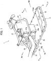
Fig. 1 ] It is a perspective view showing a contactless charging device for a vehicle according to a first embodiment of the present invention. - [
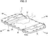
Fig. 2 ] It is a perspective view showing an electricity receiving coil unit inFig. 1 . - [
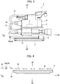
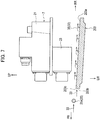
Fig. 3 ] It is a cross-sectional view taken along a line A-A inFig. 1 . - [
Fig. 4 ] It is a cross-sectional view showing a main portion extracted fromFig. 3 . - [
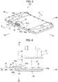
Fig. 5 ] It is a perspective view showing an electricity receiving coil unit according to a second embodiment of the present invention. - [
Fig. 6 ] It is a cross-sectional view taken along a line B-B inFig. 5 , and is equivalent toFig. 3 according to the first embodiment. - [
Fig. 7 ] It is a cross-sectional view showing a contactless charging device for a vehicle according to a third embodiment of the present invention, and is equivalent toFig. 3 according to the first embodiment. - [
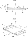
Fig. 8 ] It is a cross-sectional view showing an electricity receiving coil unit according to a fourth embodiment of the present invention, and is equivalent toFig. 4 according to the first embodiment. - [
Fig. 9 ] It is a perspective view showing an electricity receiving coil unit according to a fifth embodiment of the present invention. - [
Fig. 10 ] It is a cross-sectional view taken along a line C-C inFig. 9 , and is equivalent toFig. 3 according to the first embodiment. - Hereinafter, embodiments of the present invention will be described. Note that FR indicates a front of a vehicle, RR indicates a rear of a vehicle, RH indicates a right side in a vehicle width direction, LH indicates a left side in the vehicle width direction, UP indicates an upper-side of the vehicle, and a LW indicates a lower-side of the vehicle.
- Hereinafter, a first embodiment of the present invention will be described by using
Fig. 1 to Fig. 4 . - As shown in
Fig. 1 , acontactless charging device 1 for a vehicle according to the first embodiment includes an electricity receivingcoil unit 3 having an electricity receiving coil that generates heats due to its electrical conduction, an electriccomponent storage box 7 having at least arectifier 5, and harnesses electrically connecting the electricity receivingcoil unit 3 and the electriccomponent storage box 7 with each other. Thecontactless charging device 1 for a vehicle is disposed beneath a floor panel of a vehicle body. - As shown in
Fig. 1 to Fig. 3 , the electricity receivingcoil unit 3 is disposed at a lowermost side among components of thecontactless charging device 1 for a vehicle. Specifically, the electricity receivingcoil unit 3 is configured of a unitmain body 9 which is disposed on a lower side and whose upper side is opened, acover 11 that seals the unitmain body 9 from above, a charging coil that is accommodated within the unitmain body 9 and is not shown in the drawings, and aconnector 13 disposed at a rear end portion on an upper face of thecover 11.Plural bosses 15 are disposed at given intervals in a circumferential direction along a circumferential edge of thecover 11, and a bolt hole is formed at each of thebosses 15. Thecover 11 can be fixed onto the unitmain body 9 by inserting bolts into these bolt holes and then fastening them. - The electric
component storage box 7 is disposed over the electricity receivingcoil unit 3. Specifically, the electriccomponent storage box 7 is composed of an upper electriccomponent storage box 21 disposed at an upper position, and a lower electriccomponent storage box 23 disposed under this upper electriccomponent storage box 21. Note that, as shown inFig. 3 , therectifier 5 and various electric components are accommodated within the upper electriccomponent storage box 21. - A
first sub-harness 25 extends from afront face 23a of the lower electriccomponent storage box 23. Thisfirst sub-harness 25 extends forward from thefront face 23a of the lower electriccomponent storage box 23, and curves rightward in a vehicle width direction on a forward side of afront end 3b of anupper face 3a of the electricity receivingcoil unit 3 and then extends in the vehicle width direction, and then further curves toward a rear of the vehicle and then extends rearward, and its end is connected to theconnector 13. Here, part of the first sub-harness that extends in the vehicle width direction composes a vehicle widthdirection extending portion 25a. In this manner, the vehicle widthdirection extending portion 25a (at least part) of the first sub-harness 25 (the harness) is routed in a vicinity of thefront end 3b of theupper face 3a of the electricity receivingcoil unit 3. - A second sub-harness 27 (the harness) and a third sub-harness 29 (the harness) extend from a
front face 21a of the upper electriccomponent storage box 21. Thesecond sub-harness 27 extends forward from thefront face 21a of the upper electriccomponent storage box 21, and then curves rightward in the vehicle width direction and obliquely upward, and further curves toward the rear of the vehicle and then extends rearward. Thethird sub-harness 29 is extends forward from thefront face 21a of the upper electriccomponent storage box 21, and then curves and extends downward, and then further curves toward the rear of the vehicle and then extends rearward. - In addition, a main harness 31 (the harness) that connects a battery and a motor with each other is routed over the
upper face 3a of the electricity receivingcoil unit 3. Namely, in the vehicle body, the motor is disposed in front of the electricity receivingcoil unit 3, and the battery is disposed behind the electricity receivingcoil unit 3. Then, themain harness 31 for flowing electric current from the battery to the motor is routed so as to pass over theupper face 3a of the electricity receivingcoil unit 3. Note that, as shown inFig. 1 , themain harness 31 extends in a front-rear direction over theupper face 3a, and forms a curvingportion 31a curving rightward in the vehicle width direction at an upper side of thefront end 3b of the electricity receivingcoil unit 3. - Next, changes of flows of traveling
air 33 generated along theupper face 3a of the electricity receivingcoil unit 3 while the vehicle runs will be described. - When the
traveling air 33 flowing from the front to the rear hits the first sub-harness 25 (the harness), the second sub-harness 27 (the harness), the third sub-harness 29 (the harness) and the main harness 31 (the harness) that are mentioned above, thetraveling air 33 behind these harnesses turns intoturbulence 35 as shown inFig. 4 . In particular, theturbulence 35 is readily generated by the vehicle widthdirection extending portion 25a (at least part) of the first sub-harness 25 (the harness) and themain harness 31. Thisturbulence 35 has a larger mixing effect than that of an ordinary laminar flow, and thereby flows rearwards while removing affixes on theupper face 3a of the electricity receivingcoil unit 3. - Hereinafter, operational advantages according to the first embodiment will be described.
- (1) It includes the electricity receiving
coil unit 3 having the electricity receiving coil that generates heats due to its electrical conduction, the electriccomponent storage box 7 having at least therectifier 5, theharnesses coil unit 3 and the electriccomponent storage box 7 with each other. At least part of the harnesses is routed in the vicinity of thefront end 3b of theupper face 3a of the electricity receivingcoil unit 3.
When the vehicle runs, thetraveling air 33 hits at least part of the harnesses routed in the vicinity of thefront end 3b of theupper face 3a of the electricity receivingcoil unit 3. Then, the flows of thetraveling air 33 are made turbulent by the harnesses, and thereby the flows behind these harnesses turn into theturbulence 35. Thisturbulence 35 flows rearward while hitting theupper face 3a of the electricity receivingcoil unit 3. Therefore, even in a case where affixes such as mud or the like affixes on theupper face 3a of the electricity receivingcoil unit 3, the affixes are removed by theturbulence 35 and thereby heat-radiation performance of the electricity receivingcoil unit 3 can be maintained high. - (2) The part of the harnesses routed in the vicinity of the
front end 3b of theupper face 3a of the electricity receivingcoil unit 3 is configured by the vehicle widthdirection extending portion 25a extending in the vehicle width direction.
In the present embodiment, the vehicle widthdirection extending portion 25a of the harness(es) is formed so that its cross-sectional shape is circular. Therefore, in a case where the travelingair 33 hits the vehicle widthdirection extending portion 25a from the front side, airflows are made turbulent behind the vehicle widthdirection extending portion 25a and the affixes on theupper face 3a of the electricity receivingcoil unit 3 are removed more efficiently, so that the heat-radiation performance of the electricity receivingcoil unit 3 can be maintained higher. - (3) The
main harness 31 that connects the battery and the motor with each other is routed over theupper face 3a of the electricity receivingcoil unit 3. - The traveling
air 33 generated when the vehicle runs hits themain harness 31, and thereby theturbulence 35 is generated. According to thisturbulence 35 by themain harness 31, the affixes on theupper face 3a of the electricity receivingcoil unit 3 can be much more efficiently, and thereby the heat-radiation performance of the electricity receivingcoil unit 3 can be maintained higher. - Hereinafter, a second embodiment of the present invention will be described by using
Fig. 5 to Fig.6 . However, identical/equivalent components to those in the above-described first embodiment are labeled with identical reference signs thereto, and their detailed descriptions will be omitted. - A
junction box 141 is disposed at a front portion, in the vehicle width direction, of anupper face 103a of an electricityreceiving coil unit 103 according to the present embodiment. The first andsecond harnesses 25 and 27 (the harnesses) described in the first embodiment are connected to afront wall 141a of thisjunction box 141. Thejunction box 141 is formed by being protruded upward from theupper face 103a of the electricity receivingcoil unit 103. Specifically, thejunction box 141 is composed of thefront wall 141a extending upward from afront end 103b of theupper face 103a of the electricity receivingcoil unit 3,side walls 141b respectively extending rearward from both left and right sides of thefront wall 141a, anupper wall 141c extending rearward from an upper end of thefront wall 141a, and arear wall 141d extending obliquely downward as extending rearward from a rear end of theupper wall 141c. - Next, changes of flows of the traveling
air 33 generated along theupper face 103a of the electricity receivingcoil unit 103 while the vehicle runs will be described. - When the traveling
air 33 hits thejunction box 141 according to the present embodiment in addition to thefirst sub-harness 25, thesecond sub-harness 27, thethird sub-harness 29 and themain harness 31 that are mentioned above, the travelingair 33 behind these harnesses and thejunction box 141 turns into theturbulence 35 as shown inFig. 6 . In particular, in the present embodiment, theturbulence 35 is readily generated by the vehicle widthdirection extending portion 25a of thefirst sub-harness 25 and thefront wall 141a of thejunction box 141. Thisturbulence 35 has a larger mixing effect than that of an ordinary laminar flow, and thereby it flows rearwards while removing affixes on theupper face 103a of the electricity receivingcoil unit 103. - Hereinafter, operational advantages according to the second embodiment will be described.
- (1) The
junction box 141 that electrically connects the electricity receiving coil of the electricity receivingcoil unit 103 and thefirst sub-harness 25 extending from the electriccomponent storage box 7 with each other is disposed at the front portion of theupper face 103a of the electricity receivingcoil unit 103. - The junction box 104 protrudes upward from the
upper face 103a of the electricity receivingcoil unit 103. Therefore, when the travelingair 33 hits thejunction box 141, theturbulence 35 is generated behind thejunction box 141. According to thisturbulence 35, the affixes on theupper face 103a of the electricity receivingcoil unit 103 are removed more efficiently, and thereby the heat-radiation performance of the electricity receivingcoil unit 103 can be maintained higher. - Hereinafter, a third embodiment of the present invention will be described by using
Fig. 7 . However, identical/equivalent components to those in the above-described first to second embodiments are labeled with identical reference signs thereto, and their detailed descriptions will be omitted. - In the present embodiment, an
upper face 203a of an electricityreceiving coil unit 203 is flat, and theupper face 203a is formed on an oblique face extending obliquely downward as extending toward the rear of the vehicle. - Specifically, the
upper face 203a of the electricity receivingcoil unit 203 is formed on the oblique face extending obliquely downward as extending toward the rear of the vehicle by obliquely holding the electricity receivingcoil unit 203 according to the first embodiment so as to make its front side high and make its rear side lower. Therefore, an upper-end corner 203c of thefront end 203b is located at a higher position than a rear end of theupper face 203a, and thereby the travelingair 33 of the vehicle hits the upper-end corner 203c and then turns into theturbulence 35 behind the upper-end corner 203c. - Hereinafter, operational advantages according to the third embodiment will be described.
- (1) The
upper face 203a of the electricity receivingcoil unit 203 is flat, and theupper face 203a is formed on an oblique face extending obliquely downward as extending toward the rear of the vehicle. - The upper-
end corner 203c (the front portion) of theupper face 203a of the electricity receivingcoil unit 203 is disposed higher than the rear portion thereof. Therefore, in a case where the travelingair 33 hits the upper-end corner 203c of theupper face 203a of the electricity receivingcoil unit 203, theturbulence 35 is generated behind the upper-end corner 203c. According to thisturbulence 35, the affixes on theupper face 203a of the electricity receivingcoil unit 203 are removed more efficiently, and thereby the heat-radiation performance of the electricity receivingcoil unit 203 can be maintained higher. - Hereinafter, a fourth embodiment of the present invention will be described by using
Fig. 8 . However, identical/equivalent components to those in the above-described first to third embodiments are labeled with identical reference signs thereto, and their detailed descriptions will be omitted. - In the present embodiment, an
upper face 303a of an electricityreceiving coil unit 303 is flat, and theupper face 303a is formed on an oblique face extending obliquely downward as extending toward the rear of the vehicle. - Specifically, the electricity receiving
coil unit 303 according to the fourth embodiment is formed so that its thickness in a vertical direction is made thinner as extending from its front side toward its rear side. Namely, abottom face 303c is formed as a horizontal plane without obliquity, but theupper face 303a is formed on the oblique face extending obliquely downward as extending toward the rear of the vehicle. Therefore, an upper-end corner 303d of thefront end 303b is located at a higher position than a rear end of theupper face 303a, and thereby the travelingair 33 of the vehicle hits the upper-end corner 303d and then turns into theturbulence 35 behind the upper-end corner 303d. - Hereinafter, operational advantages according to the fourth embodiment will be described.
- (1) The
upper face 303a of the electricity receivingcoil unit 303 is flat, and theupper face 303a is formed on the oblique face extending obliquely downward as extending toward the rear of the vehicle. - The upper-
end corner 303d (the front portion) of theupper face 303a of the electricity receivingcoil unit 303 is disposed higher than the rear portion thereof. Therefore, in a case where the traveling air hits the upper-end corner 303d of theupper face 303a of the electricity receivingcoil unit 303, theturbulence 35 is generated behind the upper-end corner 303d. According to thisturbulence 35, the affixes on theupper face 303a of the electricity receivingcoil unit 303 are removed more efficiently, and thereby the heat-radiation performance of the electricity receivingcoil unit 303 can be maintained higher. - Hereinafter, a fifth embodiment of the present invention will be described by using
Fig. 9 to Fig. 10 . However, identical/equivalent components to those in the above-described first to fourth embodiments are labeled with identical reference signs thereto, and their detailed descriptions will be omitted. - In the present embodiment,
plural protrusions 410 protruding upward are disposed along the vehicle width direction at intervals at a front portion of anupper face 403a of an electricityreceiving coil unit 403. Specifically, theplural protrusions 410 are arranged along the vehicle width direction at equivalent intervals at a front end of theupper face 403a of the electricity receivingcoil unit 403. Each of theprotrusions 410 is composed of avertical wall 411 extending upward from thefront end 403b of the electricity receivingcoil unit 403, and a reinforcingmember 412 that connects a back face of thevertical wall 411 with theupper face 403a of the electricity receivingcoil unit 403 and is triangular when viewed from its side. - Hereinafter, operational advantages according to the fifth embodiment will be described.
- (1) The
plural protrusions 410 protruding upward are disposed along the vehicle width direction at intervals at the front portion of theupper face 403a of the electricity receivingcoil unit 403. - In a case where the traveling
air 33 hits theprotrusions 410 of theupper face 403a of the electricity receivingcoil unit 403, theturbulence 35 is generated behind theprotrusions 410. According to thisturbulence 35, the affixes on theupper face 403a of the electricity receivingcoil unit 403 are removed more efficiently, and thereby the heat-radiation performance of the electricity receivingcoil unit 403 can be maintained higher. - Note that the present invention is not limited to the above-described embodiments, and various modifications and changes can be adopted.
- For example, no underbody shield cover is disposed at a lower portion of the vehicle body above embodiments, but an underbody shield may be disposed beneath the electricity receiving
coil unit direction extending portion 25a of thefirst sub-harness 25 is routed on a forward side of thefront end 3b of theupper face 3a of the electricity receivingcoil unit 3, but it may be disposed above the front portion of theupper face 3a of the electricity receivingcoil unit 3. -
- 3, 103, 203, 303, 403 electricity receiving coil unit
- 3a, 103a, 203a, 303a, 403a upper face of the electricity receiving coil unit
- 3b, 103b, 203b, 303b, 403b front end of the electricity receiving coil unit
- 5 rectifier
- 7 electric component storage box
- 25 first sub harness (harness)
- 25a vehicle width direction extending portion
- 31 main harness (harness)
- 141 junction box
- 410 protrusion
Claims (6)
- A contactless charging device for a vehicle, comprising: an electricity receiving coil unit having an electricity receiving coil that generates heats due to electrical conduction thererof; an electric component storage box having at least a rectifier; and a harness electrically connecting the electricity receiving coil unit and the electric component storage box with each other, wherein
at least part of the harness is routed in a vicinity of an front end of an upper face of the electricity receiving coil unit. - The contactless charging device for a vehicle according to claim 1, wherein
the part of the harness routed in the vicinity of the front end of the upper face of the electricity receiving coil unit is configured at a vehicle width direction extending portion extending along a vehicle width direction. - The contactless charging device for a vehicle according to claim 1 or 2, wherein
a junction box that electrically connects the electricity receiving coil of the electricity receiving coil unit with the harness extending from the electric component storage box is disposed at a front portion on the upper face of the electricity receiving coil unit. - The contactless charging device for a vehicle according to any one of claims 1 to 3, wherein
the upper face of the electricity receiving coil unit is flat, and the upper face is formed on an oblique face extending obliquely downward as extending toward a rear of the vehicle. - The contactless charging device for a vehicle according to any one of claims 1 to 4, wherein
a plurality of protrusions protruding upward is disposed along a vehicle width direction at intervals at a front portion of the upper face of the electricity receiving coil unit. - The contactless charging device for a vehicle according to any one of claims 1 to 5, wherein
a main harness connecting a battery and a motor with each other is routed over the upper face of the electricity receiving coil unit.
Applications Claiming Priority (1)
| Application Number | Priority Date | Filing Date | Title |
|---|---|---|---|
| PCT/JP2015/060936 WO2016162966A1 (en) | 2015-04-08 | 2015-04-08 | Noncontact charging device for vehicle |
Publications (3)
| Publication Number | Publication Date |
|---|---|
| EP3282555A1 true EP3282555A1 (en) | 2018-02-14 |
| EP3282555A4 EP3282555A4 (en) | 2018-07-11 |
| EP3282555B1 EP3282555B1 (en) | 2019-06-12 |
Family
ID=57072590
Family Applications (1)
| Application Number | Title | Priority Date | Filing Date |
|---|---|---|---|
| EP15888459.3A Active EP3282555B1 (en) | 2015-04-08 | 2015-04-08 | Noncontact charging device for vehicle |
Country Status (5)
| Country | Link |
|---|---|
| US (1) | US10304616B2 (en) |
| EP (1) | EP3282555B1 (en) |
| JP (1) | JP6354900B2 (en) |
| CN (1) | CN107534302B (en) |
| WO (1) | WO2016162966A1 (en) |
Families Citing this family (1)
| Publication number | Priority date | Publication date | Assignee | Title |
|---|---|---|---|---|
| DE102018222457A1 (en) * | 2018-12-20 | 2020-06-25 | Audi Ag | Contactless charging device for a motor vehicle and motor vehicle |
Family Cites Families (10)
| Publication number | Priority date | Publication date | Assignee | Title |
|---|---|---|---|---|
| JP3202372B2 (en) * | 1992-12-16 | 2001-08-27 | 株式会社アドバンテスト | Heating element cooling device |
| JP4743244B2 (en) | 2008-09-18 | 2011-08-10 | トヨタ自動車株式会社 | Non-contact power receiving device |
| JP5574107B2 (en) | 2010-10-13 | 2014-08-20 | 三菱自動車工業株式会社 | Vehicle charging device |
| WO2013038591A1 (en) * | 2011-09-16 | 2013-03-21 | パナソニック株式会社 | Power-reception device, power-transmission device, and power-transfer device |
| JP5754359B2 (en) * | 2011-11-24 | 2015-07-29 | 株式会社豊田自動織機 | Non-contact power supply device and non-contact power supply system |
| JP5848182B2 (en) * | 2012-04-05 | 2016-01-27 | トヨタ自動車株式会社 | vehicle |
| WO2013168241A1 (en) * | 2012-05-09 | 2013-11-14 | トヨタ自動車株式会社 | Vehicle |
| CN103107576B (en) * | 2013-01-31 | 2015-05-20 | 浙江吉利汽车研究院有限公司杭州分公司 | Wireless charging system of electric automobile |
| JP2014193692A (en) * | 2013-03-29 | 2014-10-09 | Nissan Motor Co Ltd | Rear part structure of car body |
| JP6135425B2 (en) * | 2013-04-15 | 2017-05-31 | 日産自動車株式会社 | In-vehicle structure of non-contact power receiving device |
-
2015
- 2015-04-08 WO PCT/JP2015/060936 patent/WO2016162966A1/en not_active Ceased
- 2015-04-08 US US15/564,547 patent/US10304616B2/en active Active
- 2015-04-08 JP JP2017511388A patent/JP6354900B2/en active Active
- 2015-04-08 CN CN201580078388.XA patent/CN107534302B/en active Active
- 2015-04-08 EP EP15888459.3A patent/EP3282555B1/en active Active
Also Published As
| Publication number | Publication date |
|---|---|
| JP6354900B2 (en) | 2018-07-11 |
| EP3282555B1 (en) | 2019-06-12 |
| CN107534302B (en) | 2018-10-02 |
| WO2016162966A1 (en) | 2016-10-13 |
| US20180082779A1 (en) | 2018-03-22 |
| US10304616B2 (en) | 2019-05-28 |
| JPWO2016162966A1 (en) | 2018-03-01 |
| CN107534302A (en) | 2018-01-02 |
| EP3282555A4 (en) | 2018-07-11 |
Similar Documents
| Publication | Publication Date | Title |
|---|---|---|
| US9485881B2 (en) | Inverter cover | |
| US9409495B2 (en) | Vehicle apparatus attaching structure | |
| CN103781667B (en) | The distribution protective cover structure of electric vehicle | |
| JP6179666B2 (en) | In-vehicle structure of non-contact power receiving device | |
| US11070084B2 (en) | Vehicle | |
| JP5853714B2 (en) | Car charging socket mounting structure | |
| CN105593053A (en) | Vehicle-mounted structure of non-contact power receiving device | |
| US10065686B2 (en) | Vehicular mud guard structure | |
| EP3282555B1 (en) | Noncontact charging device for vehicle | |
| EP3082206B1 (en) | Electrical junction box | |
| US12459449B2 (en) | Wire harness routing structure for chargeable vehicle | |
| JP6131328B2 (en) | Body bumper structure | |
| US9610850B2 (en) | Vehicle charging unit | |
| US20190241134A1 (en) | Vehicle | |
| JP2015071397A (en) | Wire harness wiring structure for electric vehicles | |
| JP7316508B2 (en) | vehicle undercarriage | |
| CN108621817A (en) | Charging seat installation system and automobile | |
| WO2020137472A1 (en) | Wire harness assembly and wire harness assembly mounting structure | |
| CN108353522B (en) | Shield | |
| JP2016107830A (en) | Earth member for vehicle and arrangement structure of earth member for vehicle | |
| JP6647784B2 (en) | Arrangement structure of vehicle ground member and vehicle ground member | |
| JP2015164832A (en) | Instrument panel structure | |
| JP2019069740A (en) | Vehicular harness support structure |
Legal Events
| Date | Code | Title | Description |
|---|---|---|---|
| STAA | Information on the status of an ep patent application or granted ep patent |
Free format text: STATUS: THE INTERNATIONAL PUBLICATION HAS BEEN MADE |
|
| PUAI | Public reference made under article 153(3) epc to a published international application that has entered the european phase |
Free format text: ORIGINAL CODE: 0009012 |
|
| STAA | Information on the status of an ep patent application or granted ep patent |
Free format text: STATUS: REQUEST FOR EXAMINATION WAS MADE |
|
| 17P | Request for examination filed |
Effective date: 20170927 |
|
| AK | Designated contracting states |
Kind code of ref document: A1 Designated state(s): AL AT BE BG CH CY CZ DE DK EE ES FI FR GB GR HR HU IE IS IT LI LT LU LV MC MK MT NL NO PL PT RO RS SE SI SK SM TR |
|
| AX | Request for extension of the european patent |
Extension state: BA ME |
|
| A4 | Supplementary search report drawn up and despatched |
Effective date: 20180612 |
|
| RIC1 | Information provided on ipc code assigned before grant |
Ipc: H02J 50/10 20160101AFI20180606BHEP Ipc: B60L 11/18 20060101ALI20180606BHEP |
|
| DAV | Request for validation of the european patent (deleted) | ||
| DAX | Request for extension of the european patent (deleted) | ||
| REG | Reference to a national code |
Ref country code: DE Ref legal event code: R079 Ref document number: 602015032065 Country of ref document: DE Free format text: PREVIOUS MAIN CLASS: H02J0050000000 Ipc: H02J0050100000 |
|
| GRAP | Despatch of communication of intention to grant a patent |
Free format text: ORIGINAL CODE: EPIDOSNIGR1 |
|
| STAA | Information on the status of an ep patent application or granted ep patent |
Free format text: STATUS: GRANT OF PATENT IS INTENDED |
|
| RIC1 | Information provided on ipc code assigned before grant |
Ipc: H02J 50/10 20160101AFI20181211BHEP Ipc: B60L 11/18 20060101ALI20181211BHEP |
|
| INTG | Intention to grant announced |
Effective date: 20190108 |
|
| GRAS | Grant fee paid |
Free format text: ORIGINAL CODE: EPIDOSNIGR3 |
|
| GRAA | (expected) grant |
Free format text: ORIGINAL CODE: 0009210 |
|
| STAA | Information on the status of an ep patent application or granted ep patent |
Free format text: STATUS: THE PATENT HAS BEEN GRANTED |
|
| AK | Designated contracting states |
Kind code of ref document: B1 Designated state(s): AL AT BE BG CH CY CZ DE DK EE ES FI FR GB GR HR HU IE IS IT LI LT LU LV MC MK MT NL NO PL PT RO RS SE SI SK SM TR |
|
| REG | Reference to a national code |
Ref country code: GB Ref legal event code: FG4D |
|
| REG | Reference to a national code |
Ref country code: CH Ref legal event code: EP |
|
| REG | Reference to a national code |
Ref country code: AT Ref legal event code: REF Ref document number: 1143865 Country of ref document: AT Kind code of ref document: T Effective date: 20190615 |
|
| REG | Reference to a national code |
Ref country code: DE Ref legal event code: R096 Ref document number: 602015032065 Country of ref document: DE |
|
| REG | Reference to a national code |
Ref country code: IE Ref legal event code: FG4D |
|
| REG | Reference to a national code |
Ref country code: NL Ref legal event code: MP Effective date: 20190612 |
|
| REG | Reference to a national code |
Ref country code: LT Ref legal event code: MG4D |
|
| PG25 | Lapsed in a contracting state [announced via postgrant information from national office to epo] |
Ref country code: FI Free format text: LAPSE BECAUSE OF FAILURE TO SUBMIT A TRANSLATION OF THE DESCRIPTION OR TO PAY THE FEE WITHIN THE PRESCRIBED TIME-LIMIT Effective date: 20190612 Ref country code: LT Free format text: LAPSE BECAUSE OF FAILURE TO SUBMIT A TRANSLATION OF THE DESCRIPTION OR TO PAY THE FEE WITHIN THE PRESCRIBED TIME-LIMIT Effective date: 20190612 Ref country code: SE Free format text: LAPSE BECAUSE OF FAILURE TO SUBMIT A TRANSLATION OF THE DESCRIPTION OR TO PAY THE FEE WITHIN THE PRESCRIBED TIME-LIMIT Effective date: 20190612 Ref country code: NO Free format text: LAPSE BECAUSE OF FAILURE TO SUBMIT A TRANSLATION OF THE DESCRIPTION OR TO PAY THE FEE WITHIN THE PRESCRIBED TIME-LIMIT Effective date: 20190912 Ref country code: HR Free format text: LAPSE BECAUSE OF FAILURE TO SUBMIT A TRANSLATION OF THE DESCRIPTION OR TO PAY THE FEE WITHIN THE PRESCRIBED TIME-LIMIT Effective date: 20190612 Ref country code: AL Free format text: LAPSE BECAUSE OF FAILURE TO SUBMIT A TRANSLATION OF THE DESCRIPTION OR TO PAY THE FEE WITHIN THE PRESCRIBED TIME-LIMIT Effective date: 20190612 |
|
| PG25 | Lapsed in a contracting state [announced via postgrant information from national office to epo] |
Ref country code: RS Free format text: LAPSE BECAUSE OF FAILURE TO SUBMIT A TRANSLATION OF THE DESCRIPTION OR TO PAY THE FEE WITHIN THE PRESCRIBED TIME-LIMIT Effective date: 20190612 Ref country code: BG Free format text: LAPSE BECAUSE OF FAILURE TO SUBMIT A TRANSLATION OF THE DESCRIPTION OR TO PAY THE FEE WITHIN THE PRESCRIBED TIME-LIMIT Effective date: 20190912 Ref country code: LV Free format text: LAPSE BECAUSE OF FAILURE TO SUBMIT A TRANSLATION OF THE DESCRIPTION OR TO PAY THE FEE WITHIN THE PRESCRIBED TIME-LIMIT Effective date: 20190612 Ref country code: GR Free format text: LAPSE BECAUSE OF FAILURE TO SUBMIT A TRANSLATION OF THE DESCRIPTION OR TO PAY THE FEE WITHIN THE PRESCRIBED TIME-LIMIT Effective date: 20190913 |
|
| REG | Reference to a national code |
Ref country code: AT Ref legal event code: MK05 Ref document number: 1143865 Country of ref document: AT Kind code of ref document: T Effective date: 20190612 |
|
| PG25 | Lapsed in a contracting state [announced via postgrant information from national office to epo] |
Ref country code: EE Free format text: LAPSE BECAUSE OF FAILURE TO SUBMIT A TRANSLATION OF THE DESCRIPTION OR TO PAY THE FEE WITHIN THE PRESCRIBED TIME-LIMIT Effective date: 20190612 Ref country code: SK Free format text: LAPSE BECAUSE OF FAILURE TO SUBMIT A TRANSLATION OF THE DESCRIPTION OR TO PAY THE FEE WITHIN THE PRESCRIBED TIME-LIMIT Effective date: 20190612 Ref country code: PT Free format text: LAPSE BECAUSE OF FAILURE TO SUBMIT A TRANSLATION OF THE DESCRIPTION OR TO PAY THE FEE WITHIN THE PRESCRIBED TIME-LIMIT Effective date: 20191014 Ref country code: AT Free format text: LAPSE BECAUSE OF FAILURE TO SUBMIT A TRANSLATION OF THE DESCRIPTION OR TO PAY THE FEE WITHIN THE PRESCRIBED TIME-LIMIT Effective date: 20190612 Ref country code: CZ Free format text: LAPSE BECAUSE OF FAILURE TO SUBMIT A TRANSLATION OF THE DESCRIPTION OR TO PAY THE FEE WITHIN THE PRESCRIBED TIME-LIMIT Effective date: 20190612 Ref country code: NL Free format text: LAPSE BECAUSE OF FAILURE TO SUBMIT A TRANSLATION OF THE DESCRIPTION OR TO PAY THE FEE WITHIN THE PRESCRIBED TIME-LIMIT Effective date: 20190612 Ref country code: RO Free format text: LAPSE BECAUSE OF FAILURE TO SUBMIT A TRANSLATION OF THE DESCRIPTION OR TO PAY THE FEE WITHIN THE PRESCRIBED TIME-LIMIT Effective date: 20190612 |
|
| PG25 | Lapsed in a contracting state [announced via postgrant information from national office to epo] |
Ref country code: SM Free format text: LAPSE BECAUSE OF FAILURE TO SUBMIT A TRANSLATION OF THE DESCRIPTION OR TO PAY THE FEE WITHIN THE PRESCRIBED TIME-LIMIT Effective date: 20190612 Ref country code: ES Free format text: LAPSE BECAUSE OF FAILURE TO SUBMIT A TRANSLATION OF THE DESCRIPTION OR TO PAY THE FEE WITHIN THE PRESCRIBED TIME-LIMIT Effective date: 20190612 Ref country code: IT Free format text: LAPSE BECAUSE OF FAILURE TO SUBMIT A TRANSLATION OF THE DESCRIPTION OR TO PAY THE FEE WITHIN THE PRESCRIBED TIME-LIMIT Effective date: 20190612 Ref country code: IS Free format text: LAPSE BECAUSE OF FAILURE TO SUBMIT A TRANSLATION OF THE DESCRIPTION OR TO PAY THE FEE WITHIN THE PRESCRIBED TIME-LIMIT Effective date: 20191012 |
|
| REG | Reference to a national code |
Ref country code: DE Ref legal event code: R097 Ref document number: 602015032065 Country of ref document: DE |
|
| PG25 | Lapsed in a contracting state [announced via postgrant information from national office to epo] |
Ref country code: TR Free format text: LAPSE BECAUSE OF FAILURE TO SUBMIT A TRANSLATION OF THE DESCRIPTION OR TO PAY THE FEE WITHIN THE PRESCRIBED TIME-LIMIT Effective date: 20190612 |
|
| PLBE | No opposition filed within time limit |
Free format text: ORIGINAL CODE: 0009261 |
|
| STAA | Information on the status of an ep patent application or granted ep patent |
Free format text: STATUS: NO OPPOSITION FILED WITHIN TIME LIMIT |
|
| PG25 | Lapsed in a contracting state [announced via postgrant information from national office to epo] |
Ref country code: PL Free format text: LAPSE BECAUSE OF FAILURE TO SUBMIT A TRANSLATION OF THE DESCRIPTION OR TO PAY THE FEE WITHIN THE PRESCRIBED TIME-LIMIT Effective date: 20190612 Ref country code: DK Free format text: LAPSE BECAUSE OF FAILURE TO SUBMIT A TRANSLATION OF THE DESCRIPTION OR TO PAY THE FEE WITHIN THE PRESCRIBED TIME-LIMIT Effective date: 20190612 |
|
| 26N | No opposition filed |
Effective date: 20200313 |
|
| PG25 | Lapsed in a contracting state [announced via postgrant information from national office to epo] |
Ref country code: IS Free format text: LAPSE BECAUSE OF FAILURE TO SUBMIT A TRANSLATION OF THE DESCRIPTION OR TO PAY THE FEE WITHIN THE PRESCRIBED TIME-LIMIT Effective date: 20200224 Ref country code: SI Free format text: LAPSE BECAUSE OF FAILURE TO SUBMIT A TRANSLATION OF THE DESCRIPTION OR TO PAY THE FEE WITHIN THE PRESCRIBED TIME-LIMIT Effective date: 20190612 |
|
| PG2D | Information on lapse in contracting state deleted |
Ref country code: IS |
|
| PG25 | Lapsed in a contracting state [announced via postgrant information from national office to epo] |
Ref country code: MC Free format text: LAPSE BECAUSE OF FAILURE TO SUBMIT A TRANSLATION OF THE DESCRIPTION OR TO PAY THE FEE WITHIN THE PRESCRIBED TIME-LIMIT Effective date: 20190612 |
|
| REG | Reference to a national code |
Ref country code: CH Ref legal event code: PL |
|
| PG25 | Lapsed in a contracting state [announced via postgrant information from national office to epo] |
Ref country code: LU Free format text: LAPSE BECAUSE OF NON-PAYMENT OF DUE FEES Effective date: 20200408 Ref country code: CH Free format text: LAPSE BECAUSE OF NON-PAYMENT OF DUE FEES Effective date: 20200430 Ref country code: LI Free format text: LAPSE BECAUSE OF NON-PAYMENT OF DUE FEES Effective date: 20200430 |
|
| REG | Reference to a national code |
Ref country code: BE Ref legal event code: MM Effective date: 20200430 |
|
| PG25 | Lapsed in a contracting state [announced via postgrant information from national office to epo] |
Ref country code: BE Free format text: LAPSE BECAUSE OF NON-PAYMENT OF DUE FEES Effective date: 20200430 |
|
| PG25 | Lapsed in a contracting state [announced via postgrant information from national office to epo] |
Ref country code: IE Free format text: LAPSE BECAUSE OF NON-PAYMENT OF DUE FEES Effective date: 20200408 |
|
| PG25 | Lapsed in a contracting state [announced via postgrant information from national office to epo] |
Ref country code: MT Free format text: LAPSE BECAUSE OF FAILURE TO SUBMIT A TRANSLATION OF THE DESCRIPTION OR TO PAY THE FEE WITHIN THE PRESCRIBED TIME-LIMIT Effective date: 20190612 Ref country code: CY Free format text: LAPSE BECAUSE OF FAILURE TO SUBMIT A TRANSLATION OF THE DESCRIPTION OR TO PAY THE FEE WITHIN THE PRESCRIBED TIME-LIMIT Effective date: 20190612 |
|
| PG25 | Lapsed in a contracting state [announced via postgrant information from national office to epo] |
Ref country code: MK Free format text: LAPSE BECAUSE OF FAILURE TO SUBMIT A TRANSLATION OF THE DESCRIPTION OR TO PAY THE FEE WITHIN THE PRESCRIBED TIME-LIMIT Effective date: 20190612 |
|
| PGFP | Annual fee paid to national office [announced via postgrant information from national office to epo] |
Ref country code: DE Payment date: 20250319 Year of fee payment: 11 |
|
| PGFP | Annual fee paid to national office [announced via postgrant information from national office to epo] |
Ref country code: GB Payment date: 20260319 Year of fee payment: 12 |
|
| PGFP | Annual fee paid to national office [announced via postgrant information from national office to epo] |
Ref country code: FR Payment date: 20260320 Year of fee payment: 12 |