EP3281904B1 - Control systems and methods for elevators - Google Patents
Control systems and methods for elevators Download PDFInfo
- Publication number
- EP3281904B1 EP3281904B1 EP16306035.3A EP16306035A EP3281904B1 EP 3281904 B1 EP3281904 B1 EP 3281904B1 EP 16306035 A EP16306035 A EP 16306035A EP 3281904 B1 EP3281904 B1 EP 3281904B1
- Authority
- EP
- European Patent Office
- Prior art keywords
- elevator
- elevator car
- occupancy
- detection system
- car
- Prior art date
- Legal status (The legal status is an assumption and is not a legal conclusion. Google has not performed a legal analysis and makes no representation as to the accuracy of the status listed.)
- Active
Links
- 238000000034 method Methods 0.000 title claims description 25
- 238000001514 detection method Methods 0.000 claims description 60
- 230000008569 process Effects 0.000 description 7
- 230000003287 optical effect Effects 0.000 description 5
- 238000004891 communication Methods 0.000 description 4
- 230000007246 mechanism Effects 0.000 description 3
- 229910000831 Steel Inorganic materials 0.000 description 2
- 230000004075 alteration Effects 0.000 description 2
- 238000005259 measurement Methods 0.000 description 2
- 239000010959 steel Substances 0.000 description 2
- 230000001133 acceleration Effects 0.000 description 1
- 230000000903 blocking effect Effects 0.000 description 1
- 230000003111 delayed effect Effects 0.000 description 1
- 230000000694 effects Effects 0.000 description 1
- 238000009434 installation Methods 0.000 description 1
- 238000012986 modification Methods 0.000 description 1
- 230000004048 modification Effects 0.000 description 1
- 239000003607 modifier Substances 0.000 description 1
- 238000012545 processing Methods 0.000 description 1
- 238000006467 substitution reaction Methods 0.000 description 1
Images

Classifications
-
- B—PERFORMING OPERATIONS; TRANSPORTING
- B66—HOISTING; LIFTING; HAULING
- B66B—ELEVATORS; ESCALATORS OR MOVING WALKWAYS
- B66B1/00—Control systems of elevators in general
- B66B1/24—Control systems with regulation, i.e. with retroactive action, for influencing travelling speed, acceleration, or deceleration
- B66B1/2408—Control systems with regulation, i.e. with retroactive action, for influencing travelling speed, acceleration, or deceleration where the allocation of a call to an elevator car is of importance, i.e. by means of a supervisory or group controller
-
- B—PERFORMING OPERATIONS; TRANSPORTING
- B66—HOISTING; LIFTING; HAULING
- B66B—ELEVATORS; ESCALATORS OR MOVING WALKWAYS
- B66B1/00—Control systems of elevators in general
- B66B1/02—Control systems without regulation, i.e. without retroactive action
- B66B1/06—Control systems without regulation, i.e. without retroactive action electric
- B66B1/14—Control systems without regulation, i.e. without retroactive action electric with devices, e.g. push-buttons, for indirect control of movements
-
- B—PERFORMING OPERATIONS; TRANSPORTING
- B66—HOISTING; LIFTING; HAULING
- B66B—ELEVATORS; ESCALATORS OR MOVING WALKWAYS
- B66B1/00—Control systems of elevators in general
- B66B1/24—Control systems with regulation, i.e. with retroactive action, for influencing travelling speed, acceleration, or deceleration
- B66B1/28—Control systems with regulation, i.e. with retroactive action, for influencing travelling speed, acceleration, or deceleration electrical
-
- B—PERFORMING OPERATIONS; TRANSPORTING
- B66—HOISTING; LIFTING; HAULING
- B66B—ELEVATORS; ESCALATORS OR MOVING WALKWAYS
- B66B1/00—Control systems of elevators in general
- B66B1/34—Details, e.g. call counting devices, data transmission from car to control system, devices giving information to the control system
- B66B1/3476—Load weighing or car passenger counting devices
-
- B—PERFORMING OPERATIONS; TRANSPORTING
- B66—HOISTING; LIFTING; HAULING
- B66B—ELEVATORS; ESCALATORS OR MOVING WALKWAYS
- B66B5/00—Applications of checking, fault-correcting, or safety devices in elevators
- B66B5/0006—Monitoring devices or performance analysers
- B66B5/0012—Devices monitoring the users of the elevator system
-
- B—PERFORMING OPERATIONS; TRANSPORTING
- B66—HOISTING; LIFTING; HAULING
- B66B—ELEVATORS; ESCALATORS OR MOVING WALKWAYS
- B66B5/00—Applications of checking, fault-correcting, or safety devices in elevators
- B66B5/0006—Monitoring devices or performance analysers
- B66B5/0018—Devices monitoring the operating condition of the elevator system
- B66B5/0031—Devices monitoring the operating condition of the elevator system for safety reasons
-
- B—PERFORMING OPERATIONS; TRANSPORTING
- B66—HOISTING; LIFTING; HAULING
- B66B—ELEVATORS; ESCALATORS OR MOVING WALKWAYS
- B66B2201/00—Aspects of control systems of elevators
- B66B2201/20—Details of the evaluation method for the allocation of a call to an elevator car
- B66B2201/222—Taking into account the number of passengers present in the elevator car to be allocated
Definitions
- the subject matter disclosed herein generally relates to elevator control systems and methods of operation and, more particularly, to elevator control systems taking into account passengers already within elevator cars.
- Elevator systems are designed to efficiently move people within buildings.
- elevators have limited capacity (e.g., volume, weight, etc.) and thus can only move a certain number of people at a given time.
- the elevator call button typically enables an indication of "up” or “down,” and pressing the associated call button will indicate to an elevator controller that an elevator car traveling in the appropriate direction should stop at the requested landing floor.
- an elevator car is full (of passengers or passengers and items) such that the potential passenger cannot board the elevator car.
- the elevator car will make a stop at a landing floor, but no one may exit or enter the elevator car.
- multiple passengers may load into an elevator car to the point of capacity.
- the elevator car doors When full, the elevator car doors may start to close.
- a potential passenger can press the elevator call button, and the elevator doors may re-open, thus delaying all other passengers already boarded on the elevator car, and further the potential passenger cannot board because the elevator car is already full.
- improved elevator call can provide efficiencies in transporting people within buildings.
- US5490580 describes an automated arrangement that selects one of a plurality of load weight bypass thresholds for an elevator car. The selection depends, for example, upon the car direction and the time of day.
- an elevator control system according to claim 1.
- further embodiments of the elevator control system may include that the occupancy detection system comprises at least one detector mounted in the elevator car.
- further embodiments of the elevator control system may include that the at least one detector comprises a camera.
- further embodiments of the elevator control system may include that the at least one detector is mounted to at least one of an elevator wall or an elevator ceiling.
- further embodiments of the elevator control system may include that the predetermined threshold is a value of 50% or greater of occupancy of the elevator car.
- further embodiments of the elevator control system may include that the occupancy detection system captures a reference image of the elevator car and compares currently captured images with the reference image to determine the occupancy level.
- further embodiments of the elevator control system may include that preventing additional passengers from entering the elevator car comprises at least one of (i) prevent the elevator car from stopping at any landings where a potential passenger has requested an elevator but no current occupant/passenger has requested to exit, (ii) close elevator doors of the elevator car, or (iii) prevent reopening of the elevator doors once a door closing operation starts.
- further embodiments of the elevator control system may include a weight sensor configured to provide information to at least one of the elevator controller or the occupancy detection system such that a determination regarding the occupancy level of the elevator car is based in part on the current weight of the elevator car.
- further embodiments of the method may include that the occupancy detection system comprises at least one detector mounted in a ceiling of the elevator car.
- further embodiments of the method may include that the at least one detector comprises a camera having a fish-eye lens.
- further embodiments of the method may include that the predetermined threshold is a value of 50% or greater of occupancy of the elevator car.
- further embodiments of the method may include capturing a reference image of the elevator car and comparing a currently captured image with the reference image to determine the occupancy level.
- further embodiments of the method may include that preventing additional passengers from entering the elevator car comprises at least one of (i) preventing the elevator car from stopping at any landings where a potential passenger has requested an elevator but no current occupant/passenger has requested to exit, (ii) closing elevator doors of the elevator car, or (iii) preventing reopening of the elevator doors once a door closing operation starts.
- further embodiments of the method may include detecting a weight of the elevator car, wherein detection of the occupancy of the elevator car includes the detected weight.
- an occupancy detection system configured to efficiently move elevator cars within an elevator system such that fully occupied elevator cars are not delayed or stopped unnecessarily at floors where no passengers will exit and no potential passengers could enter the elevator car because it was full.
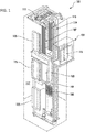
- FIG. 1 is a perspective view of an elevator system 101 including an elevator car 103, a counterweight 105, a roping 107, a guide rail 109, a machine 111, a position encoder 113, and an elevator controller 115.
- the elevator car 103 and counterweight 105 are connected to each other by the roping 107.
- the roping 107 may include or be configured as, for example, ropes, steel cables, and/or coated-steel belts.
- the counterweight 105 is configured to balance a load of the elevator car 103 and is configured to facilitate movement of the elevator car 103 concurrently and in an opposite direction with respect to the counterweight 105 within an elevator shaft 117 and along the guide rail 109.
- the roping 107 engages the machine 111, which is part of an overhead structure of the elevator system 101.
- the machine 111 is configured to control movement between the elevator car 103 and the counterweight 105.
- the position encoder 113 may be mounted on an upper sheave of a speed-governor system 119 and may be configured to provide position signals related to a position of the elevator car 103 within the elevator shaft 117. In other embodiments, the position encoder 113 may be directly mounted to a moving component of the machine 111, or may be located in other positions and/or configurations as known in the art.
- the elevator controller 115 is located, as shown, in a controller room 121 of the elevator shaft 117 and is configured to control the operation of the elevator system 101, and particularly the elevator car 103.
- the elevator controller 115 may provide drive signals to the machine 111 to control the acceleration, deceleration, leveling, stopping, etc. of the elevator car 103.
- the elevator controller 115 may also be configured to receive position signals from the position encoder 113.
- the elevator car 103 may stop at one or more landings 125 as controlled by the elevator controller 115.
- the elevator controller 115 can be located and/or configured in other locations or positions within the elevator system 101.
- the machine 111 may include a motor or similar driving mechanism.
- the machine 111 is configured to include an electrically driven motor.
- the power supply for the motor may be any power source, including a power grid, which, in combination with other components, is supplied to the motor.
- a roping system elevator systems that employ other methods and mechanisms of moving an elevator car within an elevator shaft may employ embodiments of the present disclosure.
- FIG. 1 is merely a non-limiting example presented for illustrative and explanatory purposes.
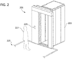
- FIG. 2 is a schematic illustration of an elevator system 201 that may incorporate embodiments disclosed herein.
- an elevator car 203 is located at a landing 225.
- the elevator car 203 may be called to the landing 225 by a passenger 227 that desires to travel to another floor within a building.
- the passenger 227 can call the elevator car 203 by pressing a call button on a hall call panel 229.
- the hall call panel 229 is in operable communication with an elevator controller (e.g., elevator controller 115 of FIG. 1 ) and can make a request such that an elevator car will stop at the landing 225.
- the hall call panel 229 can be used to request travel in a desired direction (e.g., up or down), as known in the art.
- a desired direction e.g., up or down
- the elevator system (e.g., elevator systems 101, 201) can be used to transport passengers and items between floors or landings of a building.
- elevators have limited capacity (e.g., volume, weight, etc.) and thus can only move a certain number of people or items at a given time.
- the elevator call button typically enables an indication of "up” or “down,” and pressing the associated call button will indicate to an elevator controller that an elevator car traveling in the appropriate direction should stop at the requested landing floor.
- an elevator car is full (of passengers or passengers and items) such that the potential passenger cannot board the elevator car.
- the elevator car will make a stop at a landing floor, but no one may exit or enter the elevator car. Further, in some instances, at a time of loading, multiple passengers may load into an elevator car to the point of capacity. When full, the elevator car doors may start to close. However, a potential passenger can press the elevator call button, and the elevator doors may re-open, thus delaying all other passengers already boarded on the elevator car, and further the potential passenger cannot board because the elevator car is already full. Thus, improved elevator call can provide efficiencies in transporting people within buildings.
- Embodiments provided herein are directed to elevator control systems and elevator hall call buttons that enable efficient movement of passengers and/or cargo within a building by accounting for current occupancy of an elevator car when deciding to stop an elevator car at a landing.
- Such control can be achieved with a device configured to detect an elevator occupancy and make a decision based on the detected occupancy.
- a camera or other detector can be located within an elevator car and a processor connected thereto can count the number of passengers inside an elevator car.
- a detection of occupied volume can be measured.
- a weight measurement may be made to detect a filled capacity of an elevator car.
- FIGS. 3A-3B schematic illustrations in accordance with a non-limiting embodiment in accordance with the present disclosure are shown.
- FIG. 3A is a side elevation illustration of an elevator system 301 having an elevator car 303 with an occupancy detection system 300 installed therein.
- FIG. 3B is a top down plan illustration showing a detection grid 302 of the occupancy detection system 300 of FIG. 3A .
- the elevator system 301 includes an elevator car 303 that is driven within an elevator shaft and can be called to one or more landings or floors within a structure.
- the operation of the elevator car 303 is controlled by an elevator controller 315.
- the elevator controller 315 is in communication with one or more hall call panels 329, with the hall call panels 329 having one or more hall call buttons 331 (e.g., directional buttons (up or down)).
- the hall call buttons 331 are in operable communication with the elevator controller 315.
- the hall call panel 329 sends a signal to the elevator controller 315 to request the elevator car 303 to stop at the requested landing and to travel in a desired direction (e.g., up or down).
- the elevator controller 315 will then control a machine to have the elevator car 303 stop at the requested landing when next the elevator car 303 is traveling in the requested direction.
- the elevator car 303 may be full, and thus a requesting or potential passenger may not be able to enter or load into an elevator car, even though the elevator car 303 has stopped at the requested floor.
- a full elevator car may be filled by passengers and/or cargo (e.g., items carried or transported by the passengers).
- the elevator car 303 is configured with an occupancy detection system 300.
- the occupancy detection system 300 is configured to detect if the elevator car 303 is full, and if so, the occupancy detection system 300 is configured to communicate with the elevator controller 315 to prevent the elevator car 303 from stopping at a requested floor or landing.
- the elevator car 303 can be moved quickly to appropriate floors or landings without stopping at floors or landings where no passengers will exit the elevator car 303 (e.g., floors where a request is made but the elevator is already full). That is, floors where no passengers intend to exit the elevator car and no passengers could enter because the elevator car is already full can be avoided.
- the occupancy detection system 300 includes one or more detectors 304 and a control unit 306.
- the detectors 304 can be cameras, optical detectors, infrared detectors, motion detectors, or other types of detectors as known in the art.
- a detection grid 302 is generated by the detectors 304 such that all floor space or volume of the elevator car 303 is detected by the detectors 304.
- the detection grid 302 is merely on example of how an occupancy detection system can operate in accordance with the present disclosure.
- the detectors can be located within or on a surface at a top of the elevator car 303 (e.g., a ceiling of the elevator car 303) and point downward or angled toward the elevator car floor.
- detectors can be located in the upper corners of the elevator car (e.g., on the ceiling, at the top of car walls, etc.) or elsewhere at the top of the elevator car. As will be appreciated by those of skill in the art, the one or more detectors are positioned within the elevator car such that a detection of the occupancy of the elevator car can be made.
- the control unit 306 is configured to receive data from the detectors 304 and determine an occupancy level of the elevator car 303. For example, in some embodiments, based on the detection grid 302, the control unit 306 can detect how full the elevator car 303 is. In such an example, if passengers of the elevator car 303 fill a minimum or threshold percentage of the detection grid 302, the control 306 can determine that the elevator car 303 is full and thus send a signal to the elevator controller 315 indicating that the elevator car 303 should not be stopped at any landings where no current passenger has requested to stop.
- Such decision can further be carried out with respect to door closing of an elevator car.
- the elevator car can fill up with passengers or cargo.
- the control unit 306 can receive information from the detectors 304 to detect the filling of the elevator car.
- the control unit 306 can send a signal to the elevator controller 315 (or an elevator car door controller) to close the elevator car doors or prevent the elevator car doors from re-opening if a request is made at an elevator call button once the elevator car is detected to be full.
- a software application can be employed on the control unit 306, such as stored on memory and executed by a processor.
- the control unit 306 may, in some embodiments, use various detection, counting, or other methods to determine if an elevator car is full.
- optical cameras detectors 304
- the control unit 306 further can be configured to take into account the number of passengers inside the elevator car and will reopen the elevator car door(s) only if there is free space available inside the elevator car.
- a single detector such as a fish-eye lens camera
- a single camera can be positioned in the middle of the ceiling surface of an elevator car.
- a single camera could be located on or in a side corner of the ceiling of an elevator car.
- the single camera configurations are selected and oriented such that the camera can capture an image of the whole surface of the elevator car.
- the occupancy detection system can operate in normal operation mode, and the detector (e.g., camera) will take an image of the elevator car at some predetermined interval (e.g., every 1 or 2 seconds) in order to determine the available space inside the elevator car by making a comparison with the reference image.
- the detector e.g., camera
- some predetermined interval e.g., every 1 or 2 seconds
- no further landing calls will be accepted by the elevator system until passengers or load (e.g., within a cargo elevator) currently in the elevator car exit the elevator car and reduce the occupancy level.
- a threshold or predetermined value of occupancy level can be set such that the occupancy detection system can determine that no further potential passengers should be able to board the elevator car.
- a minimum threshold could be set at any value.
- the minimum threshold can be an occupancy level or percentage that is greater than 50%.
- a minimum of 70% occupancy when comparing a currently captured image with the reference image can be set as the threshold value.
- the minimum threshold occupancy level can be set and based in part in view of observed comfort levels of passengers within an elevator car.
- the detector can include one or more thermal cameras in order to count the number of "heat points" inside an elevator car.
- a reference image may not be required.
- such a configuration may provide improved confidentiality and/or privacy for elevator occupants and passengers.
- multiple (e.g., three or more) cameras or detectors can be employed to provide multiple different points of view and/or angles. From the multiple different images or data collected from the detectors, a three dimensional model of the occupancy level of the elevator car can be obtained. Such a configuration can operate similar to a 3-D scan as known in the art.
- a car load weight device can be used in combination with the occupancy detection systems of the present disclosure.
- a weight consideration may be incorporated into the decision such that an elevator that includes a high weight can be prevented from stopping at floors and taking on additional passengers.
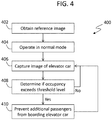
- the flow process 400 can be carried out or executed by a control unit of an occupancy detection system and/or an elevator controller, as described above.
- the flow process 400 can be carried out by an occupancy detection system that includes one or more detectors configured to detect an occupancy level of an elevator car and a control unit installed within or on an elevator car.
- the detectors can be in communication with an elevator controller that is separate or remote from an elevator car.
- a various combinations of processing can be employed without departing from the scope of the present disclosure.
- an optional reference image can be obtained using one or more detectors (e.g., optical cameras).
- the reference image can be an image of the floor space of an elevator car with no passengers or other items located within the elevator car. That is, the reference image can represent an elevator car with 0% occupancy (i.e., empty).
- the occupancy detection system can be switched to normal or operational mode.
- the operational mode can be used whenever the elevator car is in service for normal passenger transportation within and along an elevator shaft.
- the elevator car can be called to one or more different landings or floors in order to pick up or drop off passengers.
- Potential passengers can press a hall call button on a hall call panel of the elevator system.
- the hall call panel will send a request to an elevator controller to stop an elevator car at the indicated landing, when traveling in an appropriate direction within the elevator shaft.
- the occupancy detection system can obtain or capture images of the occupancy of the elevator car, as indicated at block 406. With the captured image, the occupancy detection system can determine if the occupancy of the elevator car exceeds a threshold value or level. For example, in some embodiments, if a reference image is captured at block 402, the occupancy detection system can compare a currently captured image of the elevator car with the reference image. Based on the comparison of the captured image with the reference image, the occupancy detection system can determine an occupancy level of the elevator car.
- the flow process 400 returns to block 406 and the process is repeated. That is, when it is determined at block 408 that the threshold occupancy level or value has not been exceeded, the occupancy detection system does not interfere with operation of the elevator car, and additional passengers can be allowed to enter the elevator car. For example, the elevator car can stop at a requesting landing or the elevator car doors can be re-opened when a potential passenger presses the hall call button when the elevator is on the same landing.
- the elevator car can be operated to prevent further passengers from attempting to enter the elevator car.
- the occupancy detection system can send a signal or command to an elevator controller to prevent the elevator car from stopping at any landings where a potential passenger has requested an elevator but no current occupant/passenger has requested to get off the elevator car. That is, the elevator car can be instructed to bypass floors where current passengers will not exit the elevator car.
- the elevator car doors can be commanded to close or, at least, the elevator doors can be prevented from reopening once a door closing operation starts.
- the occupancy detection system can continuously perform the flow process 400 (or portions thereof) to ensure the most efficient transportation of passengers within a building. For example, in some instances, passengers may adjust their positions and/or adjust the position of cargo (e.g., boxes, bags, possessions, etc.) such that additional room is made within elevator car. In such situations the occupancy level can decrease even though no passenger entered or exited the elevator car.
- cargo e.g., boxes, bags, possessions, etc.
- occupancy detection system as provided herein can provide improved passenger experience when using an elevator such that minimal time can be wasted. For example, only elevator cars in which a potential passenger can enter will stop at a requested floor, and thus the potential passengers may not need to repeatedly request elevator cars after the elevator doors open and the potential passenger determines that the elevator car is too full to enter. Further, the time of passengers already on an elevator car is not wasted by stopping at floors where no passenger will enter or exit from the elevator car.
- embodiments provided herein may employ reference images, thermal detection of occupancy, load weight devices, etc. and thus various markings or other detection mechanisms that may be subject to blocking by passengers can be avoided.
- embodiments provided herein can enable detection or measuring of cargo (e.g., items, boxes, bags, strollers, etc.) on the floor of an elevator car and not just detection of people.
- cargo e.g., items, boxes, bags, strollers, etc.
- the occupancy detection system can prevent the elevator car from stopping at floors where no boxes or the person will be exiting.
Description
- The subject matter disclosed herein generally relates to elevator control systems and methods of operation and, more particularly, to elevator control systems taking into account passengers already within elevator cars.
- Elevator systems are designed to efficiently move people within buildings. However, elevators have limited capacity (e.g., volume, weight, etc.) and thus can only move a certain number of people at a given time. When a potential passenger wishes to travel within an elevator car, the potential passenger must press an elevator call button. The elevator call button typically enables an indication of "up" or "down," and pressing the associated call button will indicate to an elevator controller that an elevator car traveling in the appropriate direction should stop at the requested landing floor. However, there are instances when an elevator car is full (of passengers or passengers and items) such that the potential passenger cannot board the elevator car. Thus, the elevator car will make a stop at a landing floor, but no one may exit or enter the elevator car. Further, in some instances, at a time of loading, multiple passengers may load into an elevator car to the point of capacity. When full, the elevator car doors may start to close. However, a potential passenger can press the elevator call button, and the elevator doors may re-open, thus delaying all other passengers already boarded on the elevator car, and further the potential passenger cannot board because the elevator car is already full. Thus, improved elevator call can provide efficiencies in transporting people within buildings.
-
US5490580 describes an automated arrangement that selects one of a plurality of load weight bypass thresholds for an elevator car. The selection depends, for example, upon the car direction and the time of day. - According to the invention, there is provided an elevator control system according to
claim 1. - In addition to one or more of the features described above, further embodiments of the elevator control system may include that the occupancy detection system comprises at least one detector mounted in the elevator car.
- In addition to one or more of the features described above, or as an alternative, further embodiments of the elevator control system may include that the at least one detector comprises a camera.
- In addition to one or more of the features described above, or as an alternative, further embodiments of the elevator control system may include that the at least one detector is mounted to at least one of an elevator wall or an elevator ceiling.
- In addition to one or more of the features described above, or as an alternative, further embodiments of the elevator control system may include that the predetermined threshold is a value of 50% or greater of occupancy of the elevator car.
- In addition to one or more of the features described above, or as an alternative, further embodiments of the elevator control system may include that the occupancy detection system captures a reference image of the elevator car and compares currently captured images with the reference image to determine the occupancy level.
- In addition to one or more of the features described above, or as an alternative, further embodiments of the elevator control system may include that preventing additional passengers from entering the elevator car comprises at least one of (i) prevent the elevator car from stopping at any landings where a potential passenger has requested an elevator but no current occupant/passenger has requested to exit, (ii) close elevator doors of the elevator car, or (iii) prevent reopening of the elevator doors once a door closing operation starts.
- In addition to one or more of the features described above, or as an alternative, further embodiments of the elevator control system may include a weight sensor configured to provide information to at least one of the elevator controller or the occupancy detection system such that a determination regarding the occupancy level of the elevator car is based in part on the current weight of the elevator car.
- According to the invention, there is provided a method of controlling an elevator according to claim 9.
- In addition to one or more of the features described above, further embodiments of the method may include that the occupancy detection system comprises at least one detector mounted in a ceiling of the elevator car.
- In addition to one or more of the features described above, or as an alternative, further embodiments of the method may include that the at least one detector comprises a camera having a fish-eye lens.
- In addition to one or more of the features described above, or as an alternative, further embodiments of the method may include that the predetermined threshold is a value of 50% or greater of occupancy of the elevator car.
- In addition to one or more of the features described above, or as an alternative, further embodiments of the method may include capturing a reference image of the elevator car and comparing a currently captured image with the reference image to determine the occupancy level.
- In addition to one or more of the features described above, or as an alternative, further embodiments of the method may include that preventing additional passengers from entering the elevator car comprises at least one of (i) preventing the elevator car from stopping at any landings where a potential passenger has requested an elevator but no current occupant/passenger has requested to exit, (ii) closing elevator doors of the elevator car, or (iii) preventing reopening of the elevator doors once a door closing operation starts.
- In addition to one or more of the features described above, or as an alternative, further embodiments of the method may include detecting a weight of the elevator car, wherein detection of the occupancy of the elevator car includes the detected weight.
- Technical effects of embodiments of the present disclosure include an occupancy detection system configured to efficiently move elevator cars within an elevator system such that fully occupied elevator cars are not delayed or stopped unnecessarily at floors where no passengers will exit and no potential passengers could enter the elevator car because it was full.
- The foregoing features and elements may be combined in various combinations without exclusivity, unless expressly indicated otherwise. These features and elements as well as the operation thereof will become more apparent in light of the following description and the accompanying drawings. It should be understood, however, that the following description and drawings are intended to be illustrative and explanatory in nature and non-limiting.
- The subject matter is particularly pointed out and distinctly claimed at the conclusion of the specification. The foregoing and other features, and advantages of the present disclosure are apparent from the following detailed description taken in conjunction with the accompanying drawings in which:
-
FIG. 1 is a schematic illustration of an elevator system that may employ various embodiments of the disclosure; -
FIG. 2 is a schematic illustration of a landing floor of an elevator system that may employ various embodiments of the disclosure; -
FIG. 3A is a side elevation schematic illustration of an elevator system having an occupancy detection system in accordance with an embodiment of the present disclosure; -
FIG. 3B is a top down plan illustration of the elevator car ofFIG. 3A illustrating a detection grid in accordance with an embodiment of the present disclosure; -
FIG. 4 is a flow process for operating an elevator car in accordance with an embodiment of the present disclosure. - As shown and described herein, various features of the disclosure will be presented. Various embodiments may have the same or similar features and thus the same or similar features may be labeled with the same reference numeral, but preceded by a different first number indicating the figure to which the feature is shown. Thus, for example, element "a" that is shown in FIG. X may be labeled "Xa" and a similar feature in FIG. Z may be labeled "Za." Although similar reference numbers may be used in a generic sense, various embodiments will be described and various features may include changes, alterations, modifications, etc. as will be appreciated by those of skill in the art, whether explicitly described or otherwise would be appreciated by those of skill in the art.
-
FIG. 1 is a perspective view of anelevator system 101 including anelevator car 103, acounterweight 105, aroping 107, aguide rail 109, amachine 111, aposition encoder 113, and anelevator controller 115. Theelevator car 103 andcounterweight 105 are connected to each other by theroping 107. Theroping 107 may include or be configured as, for example, ropes, steel cables, and/or coated-steel belts. Thecounterweight 105 is configured to balance a load of theelevator car 103 and is configured to facilitate movement of theelevator car 103 concurrently and in an opposite direction with respect to thecounterweight 105 within anelevator shaft 117 and along theguide rail 109. - The
roping 107 engages themachine 111, which is part of an overhead structure of theelevator system 101. Themachine 111 is configured to control movement between theelevator car 103 and thecounterweight 105. Theposition encoder 113 may be mounted on an upper sheave of a speed-governor system 119 and may be configured to provide position signals related to a position of theelevator car 103 within theelevator shaft 117. In other embodiments, theposition encoder 113 may be directly mounted to a moving component of themachine 111, or may be located in other positions and/or configurations as known in the art. - The
elevator controller 115 is located, as shown, in acontroller room 121 of theelevator shaft 117 and is configured to control the operation of theelevator system 101, and particularly theelevator car 103. For example, theelevator controller 115 may provide drive signals to themachine 111 to control the acceleration, deceleration, leveling, stopping, etc. of theelevator car 103. Theelevator controller 115 may also be configured to receive position signals from theposition encoder 113. When moving up or down within theelevator shaft 117 alongguide rail 109, theelevator car 103 may stop at one ormore landings 125 as controlled by theelevator controller 115. Although shown in acontroller room 121, those of skill in the art will appreciate that theelevator controller 115 can be located and/or configured in other locations or positions within theelevator system 101. - The
machine 111 may include a motor or similar driving mechanism. In accordance with embodiments of the disclosure, themachine 111 is configured to include an electrically driven motor. The power supply for the motor may be any power source, including a power grid, which, in combination with other components, is supplied to the motor. Although shown and described with a roping system, elevator systems that employ other methods and mechanisms of moving an elevator car within an elevator shaft may employ embodiments of the present disclosure.FIG. 1 is merely a non-limiting example presented for illustrative and explanatory purposes. -
FIG. 2 is a schematic illustration of anelevator system 201 that may incorporate embodiments disclosed herein. As shown inFIG. 2 , anelevator car 203 is located at alanding 225. Theelevator car 203 may be called to thelanding 225 by apassenger 227 that desires to travel to another floor within a building. Thepassenger 227 can call theelevator car 203 by pressing a call button on ahall call panel 229. Thehall call panel 229 is in operable communication with an elevator controller (e.g.,elevator controller 115 ofFIG. 1 ) and can make a request such that an elevator car will stop at thelanding 225. Thehall call panel 229 can be used to request travel in a desired direction (e.g., up or down), as known in the art. When theelevator car 203 reaches thelanding 225, one or more elevator doors, including elevator car doors and landing doors, may open, allowing thepassenger 227 to enter or exit theelevator car 203. - The elevator system (e.g.,
elevator systems 101, 201) can be used to transport passengers and items between floors or landings of a building. However, as noted above, elevators have limited capacity (e.g., volume, weight, etc.) and thus can only move a certain number of people or items at a given time. When a potential passenger wishes to travel within an elevator car, the potential passenger must press an elevator call button. The elevator call button typically enables an indication of "up" or "down," and pressing the associated call button will indicate to an elevator controller that an elevator car traveling in the appropriate direction should stop at the requested landing floor. However, there are instances when an elevator car is full (of passengers or passengers and items) such that the potential passenger cannot board the elevator car. Thus, the elevator car will make a stop at a landing floor, but no one may exit or enter the elevator car. Further, in some instances, at a time of loading, multiple passengers may load into an elevator car to the point of capacity. When full, the elevator car doors may start to close. However, a potential passenger can press the elevator call button, and the elevator doors may re-open, thus delaying all other passengers already boarded on the elevator car, and further the potential passenger cannot board because the elevator car is already full. Thus, improved elevator call can provide efficiencies in transporting people within buildings. - Embodiments provided herein are directed to elevator control systems and elevator hall call buttons that enable efficient movement of passengers and/or cargo within a building by accounting for current occupancy of an elevator car when deciding to stop an elevator car at a landing. Such control can be achieved with a device configured to detect an elevator occupancy and make a decision based on the detected occupancy. For example, in some embodiments, a camera or other detector can be located within an elevator car and a processor connected thereto can count the number of passengers inside an elevator car. In other embodiments, or in combination therewith, a detection of occupied volume can be measured. Further still, a weight measurement may be made to detect a filled capacity of an elevator car.
- Turning now to
FIGS. 3A-3B , schematic illustrations in accordance with a non-limiting embodiment in accordance with the present disclosure are shown.FIG. 3A is a side elevation illustration of anelevator system 301 having anelevator car 303 with anoccupancy detection system 300 installed therein.FIG. 3B is a top down plan illustration showing adetection grid 302 of theoccupancy detection system 300 ofFIG. 3A . - As shown in
FIG. 3A , theelevator system 301 is schematically shown, and those of skill in the art will appreciate that various components are omitted for ease of discussion. Theelevator system 301 includes anelevator car 303 that is driven within an elevator shaft and can be called to one or more landings or floors within a structure. The operation of theelevator car 303 is controlled by anelevator controller 315. Theelevator controller 315 is in communication with one or morehall call panels 329, with thehall call panels 329 having one or more hall call buttons 331 (e.g., directional buttons (up or down)). Thehall call buttons 331 are in operable communication with theelevator controller 315. When one or more of thehall call buttons 331 are pressed by potential passengers at a landing, thehall call panel 329 sends a signal to theelevator controller 315 to request theelevator car 303 to stop at the requested landing and to travel in a desired direction (e.g., up or down). Theelevator controller 315 will then control a machine to have theelevator car 303 stop at the requested landing when next theelevator car 303 is traveling in the requested direction. - As noted above, at times, the
elevator car 303 may be full, and thus a requesting or potential passenger may not be able to enter or load into an elevator car, even though theelevator car 303 has stopped at the requested floor. A full elevator car may be filled by passengers and/or cargo (e.g., items carried or transported by the passengers). In the embodiment ofFIGS. 3A-3B , theelevator car 303 is configured with anoccupancy detection system 300. Theoccupancy detection system 300 is configured to detect if theelevator car 303 is full, and if so, theoccupancy detection system 300 is configured to communicate with theelevator controller 315 to prevent theelevator car 303 from stopping at a requested floor or landing. That is, theelevator car 303 can be moved quickly to appropriate floors or landings without stopping at floors or landings where no passengers will exit the elevator car 303 (e.g., floors where a request is made but the elevator is already full). That is, floors where no passengers intend to exit the elevator car and no passengers could enter because the elevator car is already full can be avoided. - In the
occupancy detection system 300 ofFIGS. 3A-3B , theoccupancy detection system 300 includes one ormore detectors 304 and acontrol unit 306. Thedetectors 304 can be cameras, optical detectors, infrared detectors, motion detectors, or other types of detectors as known in the art. Adetection grid 302 is generated by thedetectors 304 such that all floor space or volume of theelevator car 303 is detected by thedetectors 304. Thedetection grid 302 is merely on example of how an occupancy detection system can operate in accordance with the present disclosure. The detectors can be located within or on a surface at a top of the elevator car 303 (e.g., a ceiling of the elevator car 303) and point downward or angled toward the elevator car floor. In other embodiments, or in combination therewith, detectors can be located in the upper corners of the elevator car (e.g., on the ceiling, at the top of car walls, etc.) or elsewhere at the top of the elevator car. As will be appreciated by those of skill in the art, the one or more detectors are positioned within the elevator car such that a detection of the occupancy of the elevator car can be made. - The
control unit 306 is configured to receive data from thedetectors 304 and determine an occupancy level of theelevator car 303. For example, in some embodiments, based on thedetection grid 302, thecontrol unit 306 can detect how full theelevator car 303 is. In such an example, if passengers of theelevator car 303 fill a minimum or threshold percentage of thedetection grid 302, thecontrol 306 can determine that theelevator car 303 is full and thus send a signal to theelevator controller 315 indicating that theelevator car 303 should not be stopped at any landings where no current passenger has requested to stop. - Such decision can further be carried out with respect to door closing of an elevator car. For example, at any given landing, even with a non-filled elevator car, the elevator car can fill up with passengers or cargo. Accordingly, even during a loading time (e.g., located at a landing with the doors open), the
control unit 306 can receive information from thedetectors 304 to detect the filling of the elevator car. When the elevator car is detected as full, thecontrol unit 306 can send a signal to the elevator controller 315 (or an elevator car door controller) to close the elevator car doors or prevent the elevator car doors from re-opening if a request is made at an elevator call button once the elevator car is detected to be full. - In some embodiments, a software application can be employed on the
control unit 306, such as stored on memory and executed by a processor. Thecontrol unit 306 may, in some embodiments, use various detection, counting, or other methods to determine if an elevator car is full. For example, in one non-limiting embodiment, optical cameras (detectors 304) can be used to transmit image data to thecontrol unit 306 and a Viola-Jones object detection framework can be used to count the number of passengers (=object) present in the elevator car. Thecontrol unit 306 further can be configured to take into account the number of passengers inside the elevator car and will reopen the elevator car door(s) only if there is free space available inside the elevator car. - In one non-limiting embodiment, a single detector, such as a fish-eye lens camera, can be positioned in the middle of the ceiling surface of an elevator car. In other embodiments, a single camera could be located on or in a side corner of the ceiling of an elevator car. The single camera configurations are selected and oriented such that the camera can capture an image of the whole surface of the elevator car. When the occupancy detection system is first put into service (e.g., just after installation of the elevator car), the occupancy detection system will use the associated detector to take a first image as a "reference image" of an empty elevator car (e.g., occupancy level = 0%). Then, the occupancy detection system can operate in normal operation mode, and the detector (e.g., camera) will take an image of the elevator car at some predetermined interval (e.g., every 1 or 2 seconds) in order to determine the available space inside the elevator car by making a comparison with the reference image. When the elevator car is determined to be full, no further landing calls will be accepted by the elevator system until passengers or load (e.g., within a cargo elevator) currently in the elevator car exit the elevator car and reduce the occupancy level.
- In some non-limiting embodiments, a threshold or predetermined value of occupancy level can be set such that the occupancy detection system can determine that no further potential passengers should be able to board the elevator car. For example, a minimum threshold could be set at any value. For example, in some embodiments, the minimum threshold can be an occupancy level or percentage that is greater than 50%. Further, in some embodiments, a minimum of 70% occupancy when comparing a currently captured image with the reference image can be set as the threshold value. The minimum threshold occupancy level can be set and based in part in view of observed comfort levels of passengers within an elevator car.
- In another example embodiment, or in combination with an optical camera, the detector can include one or more thermal cameras in order to count the number of "heat points" inside an elevator car. In such an embodiment, a reference image may not be required. Further, advantageously, such a configuration may provide improved confidentiality and/or privacy for elevator occupants and passengers.
- Further still, in some embodiments, multiple (e.g., three or more) cameras or detectors can be employed to provide multiple different points of view and/or angles. From the multiple different images or data collected from the detectors, a three dimensional model of the occupancy level of the elevator car can be obtained. Such a configuration can operate similar to a 3-D scan as known in the art.
- In another embodiment, which can be combined with the above described embodiments, a car load weight device can be used in combination with the occupancy detection systems of the present disclosure. For example, in addition to making an optical detection of the occupancy, a weight consideration may be incorporated into the decision such that an elevator that includes a high weight can be prevented from stopping at floors and taking on additional passengers.
- Turning now to
FIG. 4 , a flow process related to the present disclosure is shown. Theflow process 400 can be carried out or executed by a control unit of an occupancy detection system and/or an elevator controller, as described above. Theflow process 400, for example, can be carried out by an occupancy detection system that includes one or more detectors configured to detect an occupancy level of an elevator car and a control unit installed within or on an elevator car. In other embodiments, the detectors can be in communication with an elevator controller that is separate or remote from an elevator car. Further still, a various combinations of processing can be employed without departing from the scope of the present disclosure. - At
block 402, an optional reference image can be obtained using one or more detectors (e.g., optical cameras). The reference image can be an image of the floor space of an elevator car with no passengers or other items located within the elevator car. That is, the reference image can represent an elevator car with 0% occupancy (i.e., empty). - At
block 404, the occupancy detection system can be switched to normal or operational mode. The operational mode can be used whenever the elevator car is in service for normal passenger transportation within and along an elevator shaft. In normal or operational mode, the elevator car can be called to one or more different landings or floors in order to pick up or drop off passengers. Potential passengers can press a hall call button on a hall call panel of the elevator system. The hall call panel will send a request to an elevator controller to stop an elevator car at the indicated landing, when traveling in an appropriate direction within the elevator shaft. - At the same time, or continuously, the occupancy detection system can obtain or capture images of the occupancy of the elevator car, as indicated at
block 406. With the captured image, the occupancy detection system can determine if the occupancy of the elevator car exceeds a threshold value or level. For example, in some embodiments, if a reference image is captured atblock 402, the occupancy detection system can compare a currently captured image of the elevator car with the reference image. Based on the comparison of the captured image with the reference image, the occupancy detection system can determine an occupancy level of the elevator car. - If it is determined that the elevator car still has room (i.e., "NO"), the
flow process 400 returns to block 406 and the process is repeated. That is, when it is determined atblock 408 that the threshold occupancy level or value has not been exceeded, the occupancy detection system does not interfere with operation of the elevator car, and additional passengers can be allowed to enter the elevator car. For example, the elevator car can stop at a requesting landing or the elevator car doors can be re-opened when a potential passenger presses the hall call button when the elevator is on the same landing. - However, if it is determined that the elevator car is full at block 408 (e.g., the occupancy threshold level or value is determined to be exceeded), at
block 410 the elevator car can be operated to prevent further passengers from attempting to enter the elevator car. For example, in some embodiments, when it is determined "YES" atblock 408, the occupancy detection system can send a signal or command to an elevator controller to prevent the elevator car from stopping at any landings where a potential passenger has requested an elevator but no current occupant/passenger has requested to get off the elevator car. That is, the elevator car can be instructed to bypass floors where current passengers will not exit the elevator car. In another example, if the elevator car is at a landing and loading passengers, and the occupancy detection system determines atblock 408 that the elevator car is full ("YES"), then the elevator car doors can be commanded to close or, at least, the elevator doors can be prevented from reopening once a door closing operation starts. - Even with operation such that further passengers are prevented from boarding, as described above, the occupancy detection system can continuously perform the flow process 400 (or portions thereof) to ensure the most efficient transportation of passengers within a building. For example, in some instances, passengers may adjust their positions and/or adjust the position of cargo (e.g., boxes, bags, possessions, etc.) such that additional room is made within elevator car. In such situations the occupancy level can decrease even though no passenger entered or exited the elevator car.
- Accordingly, occupancy detection system as provided herein can provide improved passenger experience when using an elevator such that minimal time can be wasted. For example, only elevator cars in which a potential passenger can enter will stop at a requested floor, and thus the potential passengers may not need to repeatedly request elevator cars after the elevator doors open and the potential passenger determines that the elevator car is too full to enter. Further, the time of passengers already on an elevator car is not wasted by stopping at floors where no passenger will enter or exit from the elevator car.
- Further, advantageously, embodiments provided herein may employ reference images, thermal detection of occupancy, load weight devices, etc. and thus various markings or other detection mechanisms that may be subject to blocking by passengers can be avoided. Moreover, advantageously, embodiments provided herein can enable detection or measuring of cargo (e.g., items, boxes, bags, strollers, etc.) on the floor of an elevator car and not just detection of people. Thus, if an elevator has a single human occupant but is otherwise full of boxes being moved within a building, the occupancy detection system can prevent the elevator car from stopping at floors where no boxes or the person will be exiting.
- The use of the terms "a," "an," "the," and similar references in the context of description (especially in the context of the following claims) are to be construed to cover both the singular and the plural, unless otherwise indicated herein or specifically contradicted by context. The modifier "about" used in connection with a quantity is inclusive of the stated value and has the meaning dictated by the context (e.g., it includes the degree of error associated with measurement of the particular quantity). All ranges disclosed herein are inclusive of the endpoints, and the endpoints are independently combinable with each other.
- While the present disclosure has been described in detail in connection with only a limited number of embodiments, it should be readily understood that the present disclosure is not limited to such disclosed embodiments. Rather, the present disclosure can be modified to incorporate any number of variations, alterations, substitutions, combinations, sub-combinations, or equivalent arrangements not heretofore described, but which are commensurate with the scope of the claims. Additionally, while various embodiments of the present disclosure have been described, it is to be understood that aspects of the present disclosure may include only some of the described embodiments.
- Accordingly, the present disclosure is not to be seen as limited by the foregoing description, but is only limited by the scope of the appended claims.
Claims (15)
- An elevator control system (101, 201, 301) comprising:an elevator car (103, 203, 303);an elevator controller (115, 315); andan occupancy detection system (300) configured to detect an occupancy level within the elevator car (103, 203, 303), the occupancy detection system (300) comprising at least one camera,wherein the elevator controller (115, 315) and the occupancy detection system (300) are arranged to control the elevator car (103, 203, 303) to prevent additional passengers (227) from entering the elevator car (103, 203, 303) when the occupancy detection system (300) detects an occupancy level above a predetermined threshold;characterised in that:
the elevator controller (115, 315) and the occupancy detection system (300) are arranged to control the elevator car (103, 203, 303) such that if a request is made at an elevator call button (331), the elevator controller (115, 315) will reopen the elevator car door(s) only if there is free space available inside the elevator car (103, 203, 303). - The elevator control system (101, 201, 301) of claim 1, wherein the occupancy detection system (300) comprises at least one detector (304) mounted in the elevator car (103, 203, 303).
- The elevator control system (101, 201, 301) of claim 2, wherein the at least one detector (304) comprises a camera.
- The elevator control system (101, 201, 301) of claim 2, wherein the at least one detector (304) is mounted to at least one of an elevator wall or an elevator ceiling.
- The elevator control system (101, 201, 301) of any of the preceding claims, wherein the predetermined threshold is a value of 50% or greater of occupancy of the elevator car (103, 203, 303).
- The elevator control system (101, 201, 301) of any of the preceding claims, wherein the occupancy detection system (300) captures a reference image of the elevator car (103, 203, 303) and compares currently captured images with the reference image to determine the occupancy level.
- The elevator control system (101, 201, 301) of any of the preceding claims, wherein preventing additional passengers (227) from entering the elevator car (103, 203, 303) comprises at least one of (i) prevent the elevator car (103, 203, 303) from stopping at any landings (225) where a potential passenger (227) has requested an elevator (103, 203, 303) but no current occupant/passenger has requested to exit, (ii) close elevator doors of the elevator car (103, 203, 303), or (iii) prevent reopening of the elevator doors once a door closing operation starts.
- The elevator control system (101, 201, 301) of any of the preceding claims, further comprising a weight sensor configured to provide information to at least one of the elevator controller (115, 315) or the occupancy detection system (300) such that a determination regarding the occupancy level of the elevator car (103, 203, 303) is based in part on the current weight of the elevator car (103, 203, 303).
- A method (400) of controlling an elevator comprising:detecting an occupancy level within an elevator car (103, 203, 303) with an occupancy detection system (300); andpreventing (410) additional passengers (227) from entering the elevator car (103, 203, 303) when the occupancy detection system (300) detects (408) an occupancy level above a predetermined threshold;characterised by:
if a request is made at an elevator call button (331), reopening the elevator car door(s) only if there is free space available inside the elevator car (103, 203, 303). - The method (400) of claim 9, wherein the occupancy detection system (300) comprises at least one detector (304) mounted in a ceiling of the elevator car (103, 203, 303).
- The method (400) of claim 10, wherein the at least one detector (304) comprises a camera having a fish-eye lens.
- The method (400) of any of claims 9-11, wherein the predetermined threshold is a value of 50% or greater of occupancy of the elevator car (103, 203, 303).
- The method (400) of any of claims 9-12, further comprising capturing (402) a reference image of the elevator car (103, 203, 303) and comparing a currently captured image with the reference image to determine the occupancy level.
- The method (400) of any of claims 9-13, wherein preventing (410) additional passengers from entering the elevator car (103, 203, 303) comprises at least one of (i) preventing the elevator car (103, 203, 303) from stopping at any landings (225) where a potential passenger (227) has requested an elevator but no current occupant/passenger has requested to exit, (ii) closing elevator doors of the elevator car (103, 203, 303), or (iii) preventing reopening of the elevator doors once a door closing operation starts.
- The method (400) of any of claims 9-14, further comprising detecting a weight of the elevator car (103, 203, 303), wherein detection of the occupancy of the elevator car (103, 203, 303) includes the detected weight.
Priority Applications (3)
| Application Number | Priority Date | Filing Date | Title |
|---|---|---|---|
| EP16306035.3A EP3281904B1 (en) | 2016-08-09 | 2016-08-09 | Control systems and methods for elevators |
| US15/666,610 US10822196B2 (en) | 2016-08-09 | 2017-08-02 | Control systems and methods for elevators |
| CN201710670355.5A CN107697754B (en) | 2016-08-09 | 2017-08-08 | Control system and method for elevator |
Applications Claiming Priority (1)
| Application Number | Priority Date | Filing Date | Title |
|---|---|---|---|
| EP16306035.3A EP3281904B1 (en) | 2016-08-09 | 2016-08-09 | Control systems and methods for elevators |
Publications (2)
| Publication Number | Publication Date |
|---|---|
| EP3281904A1 EP3281904A1 (en) | 2018-02-14 |
| EP3281904B1 true EP3281904B1 (en) | 2020-03-25 |
Family
ID=56683872
Family Applications (1)
| Application Number | Title | Priority Date | Filing Date |
|---|---|---|---|
| EP16306035.3A Active EP3281904B1 (en) | 2016-08-09 | 2016-08-09 | Control systems and methods for elevators |
Country Status (3)
| Country | Link |
|---|---|
| US (1) | US10822196B2 (en) |
| EP (1) | EP3281904B1 (en) |
| CN (1) | CN107697754B (en) |
Families Citing this family (18)
| Publication number | Priority date | Publication date | Assignee | Title |
|---|---|---|---|---|
| EP3224177B1 (en) * | 2014-11-26 | 2020-01-15 | Otis Elevator Company | Elevator security and control system based on passenger movement |
| EP3281904B1 (en) * | 2016-08-09 | 2020-03-25 | Otis Elevator Company | Control systems and methods for elevators |
| DE102016117387B4 (en) * | 2016-09-15 | 2019-03-07 | Deutsche Post Ag | Method for securing a transfer point |
| EP3473574A1 (en) * | 2017-10-17 | 2019-04-24 | KONE Corporation | Diagnostics solution for elevators |
| EP3543189B1 (en) | 2018-03-19 | 2022-07-27 | Otis Elevator Company | Elevator car operation based on its occupancy |
| US11745978B2 (en) * | 2018-07-25 | 2023-09-05 | Otis Elevator Company | Method and apparatus for elevators to detect concealed object and inform building management system |
| US20200031612A1 (en) * | 2018-07-25 | 2020-01-30 | Otis Elevator Company | Dynamic car assignment process |
| JP6679151B1 (en) * | 2019-01-08 | 2020-04-15 | 東芝エレベータ株式会社 | Elevator control equipment |
| US11767193B2 (en) | 2019-01-28 | 2023-09-26 | Otis Elevator Company | Elevator call registration when a car is full |
| EP3702308A1 (en) * | 2019-03-01 | 2020-09-02 | Otis Elevator Company | Elevator cabin |
| CN110077939A (en) * | 2019-06-01 | 2019-08-02 | 汪学品 | The carriage and elevator control method of unnecessary stopping are avoided after a kind of elevator cars with full load |
| CN110921453B (en) * | 2019-12-06 | 2023-08-11 | 福建快科城建增设电梯股份有限公司 | Elevator system capable of accurately judging full load and working method |
| CN113401753A (en) * | 2020-03-16 | 2021-09-17 | 奥的斯电梯公司 | Elevator system crowd detection by robot |
| JP6968943B1 (en) * | 2020-07-15 | 2021-11-24 | 東芝エレベータ株式会社 | Elevator user detection system |
| CA3153707A1 (en) * | 2021-04-13 | 2022-10-13 | Appana Industries LLC | Systems and methods for determining elevator loads |
| JP7409578B2 (en) | 2021-10-19 | 2024-01-09 | 三菱電機ビルソリューションズ株式会社 | elevator |
| WO2023197141A1 (en) * | 2022-04-12 | 2023-10-19 | Kone Corporation | Determination of a baseline image for fill level calculations of an elevator car |
| CN115289623A (en) * | 2022-07-15 | 2022-11-04 | 珠海格力电器股份有限公司 | Control method and system of elevator air conditioner |
Family Cites Families (39)
| Publication number | Priority date | Publication date | Assignee | Title |
|---|---|---|---|---|
| US3973649A (en) | 1974-01-30 | 1976-08-10 | Hitachi, Ltd. | Elevator control apparatus |
| US4555724A (en) * | 1983-10-21 | 1985-11-26 | Westinghouse Electric Corp. | Elevator system |
| JP2573715B2 (en) | 1990-03-28 | 1997-01-22 | 三菱電機株式会社 | Elevator control device |
| EP0452130A3 (en) | 1990-04-12 | 1992-01-22 | Otis Elevator Company | Controlling door dwell time |
| FI93634C (en) | 1992-06-01 | 1995-05-10 | Kone Oy | Method and apparatus for controlling elevator doors |
| JP3454899B2 (en) * | 1993-04-07 | 2003-10-06 | オーチス エレベータ カンパニー | Apparatus and method for automatic selection of load weight bypass threshold for elevator system |
| JPH07215611A (en) | 1994-01-27 | 1995-08-15 | Toshiba Corp | Degree of car congestion detector for elevator |
| JPH07215612A (en) | 1994-02-02 | 1995-08-15 | Matsushita Electric Ind Co Ltd | Number of passenger getting in/off controller |
| US6173816B1 (en) | 1997-12-30 | 2001-01-16 | Otis Elevator Company | Hallway-entered destination information in elevator dispatching |
| JP2000034079A (en) | 1998-07-21 | 2000-02-02 | Hitachi Ltd | Group supervisory operation control device for elevator |
| US6615175B1 (en) | 1999-06-10 | 2003-09-02 | Robert F. Gazdzinski | “Smart” elevator system and method |
| JP2003012243A (en) | 2001-07-04 | 2003-01-15 | Mitsubishi Electric Corp | Elevator control system |
| AU2004320284B2 (en) * | 2004-05-26 | 2009-07-30 | Otis Elevator Company | Passenger guiding system for a passenger transportation system |
| CN1953924A (en) | 2004-07-08 | 2007-04-25 | 三菱电机株式会社 | Control device of elevator |
| US8334906B2 (en) | 2006-05-24 | 2012-12-18 | Objectvideo, Inc. | Video imagery-based sensor |
| CN101959785B (en) * | 2008-03-06 | 2014-04-30 | 因温特奥股份公司 | Lift system and method for servicing such a lift system |
| JP2011032087A (en) | 2009-08-06 | 2011-02-17 | Mitsubishi Electric Building Techno Service Co Ltd | Elevator control device |
| WO2012022827A1 (en) * | 2010-08-19 | 2012-02-23 | Kone Corporation | Passenger flow management system |
| CN103328369B (en) * | 2010-12-22 | 2016-03-30 | 因温特奥股份公司 | The Packed lift car floor of tool |
| JP2013056720A (en) * | 2011-09-07 | 2013-03-28 | Toshiba Elevator Co Ltd | Elevator operation control method, and device and system for controlling elevator using the same |
| JP6033695B2 (en) | 2013-01-28 | 2016-11-30 | 株式会社日立製作所 | Elevator monitoring device and elevator monitoring method |
| EP2813457B1 (en) * | 2013-06-10 | 2016-03-23 | Kone Corporation | Method and apparatus for controlling an elevator group |
| JP6131137B2 (en) * | 2013-07-19 | 2017-05-17 | 株式会社日立製作所 | Elevator control device |
| FI124518B (en) * | 2013-11-19 | 2014-09-30 | Kone Corp | Lift system |
| CN105793181B (en) * | 2013-12-09 | 2017-10-13 | 因温特奥股份公司 | It is used for the device and corresponding method for determining the position of Elevator weight sensor on lift facility |
| US9573789B2 (en) * | 2014-03-27 | 2017-02-21 | Thyssenkrupp Elevator Corporation | Elevator load detection system and method |
| CN104340803A (en) * | 2014-10-23 | 2015-02-11 | 重庆市特种设备检测研究院 | Elevator space overload detection device and method based on infrared dot matrix detection |
| WO2016073067A1 (en) * | 2014-11-03 | 2016-05-12 | Otis Elevator Company | Elevator passenger tracking control and call cancellation system |
| EP3224177B1 (en) | 2014-11-26 | 2020-01-15 | Otis Elevator Company | Elevator security and control system based on passenger movement |
| US9463808B2 (en) * | 2015-03-10 | 2016-10-11 | Lenovo (Singapore) Pte. Ltd. | Determining available capacity in a transportation mechanism |
| CN104828664B (en) * | 2015-04-03 | 2020-05-22 | 奥的斯电梯公司 | Automatic debugging system and method |
| US10239728B2 (en) * | 2015-04-09 | 2019-03-26 | Carrier Corporation | Intelligent building system for providing elevator occupancy information with anonymity |
| CN204675540U (en) * | 2015-06-02 | 2015-09-30 | 苏州经贸职业技术学院 | The full operation control system of a kind of lift car |
| CN105438899B (en) * | 2015-12-31 | 2017-11-07 | 青岛高校信息产业股份有限公司 | Elevator control method and device under fully loaded critical condition |
| JP6092433B1 (en) * | 2016-01-13 | 2017-03-08 | 東芝エレベータ株式会社 | Elevator boarding detection system |
| CN105692373A (en) * | 2016-03-11 | 2016-06-22 | 成都爆米花信息技术有限公司 | Elevator space overload detecting method |
| EP3281904B1 (en) * | 2016-08-09 | 2020-03-25 | Otis Elevator Company | Control systems and methods for elevators |
| US10308477B2 (en) * | 2016-10-24 | 2019-06-04 | Echostar Technologies International Corporation | Smart elevator movement |
| US11148908B2 (en) * | 2018-10-25 | 2021-10-19 | Otis Elevator Company | Elevator door with sensor for determining whether to reopen door |
-
2016
- 2016-08-09 EP EP16306035.3A patent/EP3281904B1/en active Active
-
2017
- 2017-08-02 US US15/666,610 patent/US10822196B2/en active Active
- 2017-08-08 CN CN201710670355.5A patent/CN107697754B/en active Active
Non-Patent Citations (1)
| Title |
|---|
| None * |
Also Published As
| Publication number | Publication date |
|---|---|
| US20180044132A1 (en) | 2018-02-15 |
| CN107697754A (en) | 2018-02-16 |
| CN107697754B (en) | 2022-03-01 |
| EP3281904A1 (en) | 2018-02-14 |
| US10822196B2 (en) | 2020-11-03 |
Similar Documents
| Publication | Publication Date | Title |
|---|---|---|
| EP3281904B1 (en) | Control systems and methods for elevators | |
| CN110027957B (en) | Emergency monitoring system for elevator | |
| KR101130926B1 (en) | Brake device for elevator | |
| CN107207184B (en) | Out-of-group operation for multi-car hoistway systems | |
| CN108083040B (en) | Linkage type elevator outbound control system and elevator controller | |
| CN101092220A (en) | Lift facility and method for operating a lift facility | |
| US20180105397A1 (en) | Elevator doorway display systems for elevator cars | |
| CN107250016B (en) | Method for operating elevator device | |
| EP2927174A1 (en) | Elevator system | |
| EP3604192A1 (en) | Elevator door control for deboarding passengers in multidoor elevators | |
| EP3351498A1 (en) | Elevator hover mode operation using sensor-based potential load change detection | |
| US20180093858A1 (en) | Method for occupant evacuation operation utilizing multi-compartment elevators | |
| US7644808B2 (en) | Door device of elevator | |
| US20190322482A1 (en) | Automatic cognitive analysis of elevators to reduce passenger wait time | |
| JP6538142B2 (en) | Elevator group management control system and elevator control method | |
| CN101195455B (en) | Automatic maintaining and repairing operation equipment for elevator | |
| EP3650384B1 (en) | System for monitoring lobby activity to determine whether to cancel elevator service | |
| EP3301054B1 (en) | Optimized occupant evacuation operation by utilizing remaining capacity for multi-copartment elevators | |
| EP3617113A1 (en) | Last-minute hall call request to a departing cab using gesture | |
| EP3301053B1 (en) | Re-dispatching unoccupied elevator car for occupant evacuation operation | |
| US20190389695A1 (en) | Elevator system | |
| WO2019106778A1 (en) | Elevator control device, elevator, and elevator control method | |
| EP4074640A1 (en) | Systems and methods for determining elevator loads | |
| JP2002145551A (en) | Device and method for rescue operation of double-deck elevator | |
| CN117623021A (en) | Elevator device |
Legal Events
| Date | Code | Title | Description |
|---|---|---|---|
| PUAI | Public reference made under article 153(3) epc to a published international application that has entered the european phase |
Free format text: ORIGINAL CODE: 0009012 |
|
| STAA | Information on the status of an ep patent application or granted ep patent |
Free format text: STATUS: THE APPLICATION HAS BEEN PUBLISHED |
|
| AK | Designated contracting states |
Kind code of ref document: A1 Designated state(s): AL AT BE BG CH CY CZ DE DK EE ES FI FR GB GR HR HU IE IS IT LI LT LU LV MC MK MT NL NO PL PT RO RS SE SI SK SM TR |
|
| AX | Request for extension of the european patent |
Extension state: BA ME |
|
| STAA | Information on the status of an ep patent application or granted ep patent |
Free format text: STATUS: REQUEST FOR EXAMINATION WAS MADE |
|
| 17P | Request for examination filed |
Effective date: 20180810 |
|
| RBV | Designated contracting states (corrected) |
Designated state(s): AL AT BE BG CH CY CZ DE DK EE ES FI FR GB GR HR HU IE IS IT LI LT LU LV MC MK MT NL NO PL PT RO RS SE SI SK SM TR |
|
| GRAP | Despatch of communication of intention to grant a patent |
Free format text: ORIGINAL CODE: EPIDOSNIGR1 |
|
| STAA | Information on the status of an ep patent application or granted ep patent |
Free format text: STATUS: GRANT OF PATENT IS INTENDED |
|
| INTG | Intention to grant announced |
Effective date: 20191004 |
|
| GRAS | Grant fee paid |
Free format text: ORIGINAL CODE: EPIDOSNIGR3 |
|
| GRAA | (expected) grant |
Free format text: ORIGINAL CODE: 0009210 |
|
| STAA | Information on the status of an ep patent application or granted ep patent |
Free format text: STATUS: THE PATENT HAS BEEN GRANTED |
|
| AK | Designated contracting states |
Kind code of ref document: B1 Designated state(s): AL AT BE BG CH CY CZ DE DK EE ES FI FR GB GR HR HU IE IS IT LI LT LU LV MC MK MT NL NO PL PT RO RS SE SI SK SM TR |
|
| REG | Reference to a national code |
Ref country code: GB Ref legal event code: FG4D |
|
| REG | Reference to a national code |
Ref country code: AT Ref legal event code: REF Ref document number: 1248333 Country of ref document: AT Kind code of ref document: T Effective date: 20200415 Ref country code: IE Ref legal event code: FG4D |
|
| REG | Reference to a national code |
Ref country code: DE Ref legal event code: R096 Ref document number: 602016032453 Country of ref document: DE |
|
| PG25 | Lapsed in a contracting state [announced via postgrant information from national office to epo] |
Ref country code: FI Free format text: LAPSE BECAUSE OF FAILURE TO SUBMIT A TRANSLATION OF THE DESCRIPTION OR TO PAY THE FEE WITHIN THE PRESCRIBED TIME-LIMIT Effective date: 20200325 Ref country code: NO Free format text: LAPSE BECAUSE OF FAILURE TO SUBMIT A TRANSLATION OF THE DESCRIPTION OR TO PAY THE FEE WITHIN THE PRESCRIBED TIME-LIMIT Effective date: 20200625 Ref country code: RS Free format text: LAPSE BECAUSE OF FAILURE TO SUBMIT A TRANSLATION OF THE DESCRIPTION OR TO PAY THE FEE WITHIN THE PRESCRIBED TIME-LIMIT Effective date: 20200325 |
|
| PG25 | Lapsed in a contracting state [announced via postgrant information from national office to epo] |
Ref country code: BG Free format text: LAPSE BECAUSE OF FAILURE TO SUBMIT A TRANSLATION OF THE DESCRIPTION OR TO PAY THE FEE WITHIN THE PRESCRIBED TIME-LIMIT Effective date: 20200625 Ref country code: SE Free format text: LAPSE BECAUSE OF FAILURE TO SUBMIT A TRANSLATION OF THE DESCRIPTION OR TO PAY THE FEE WITHIN THE PRESCRIBED TIME-LIMIT Effective date: 20200325 Ref country code: LV Free format text: LAPSE BECAUSE OF FAILURE TO SUBMIT A TRANSLATION OF THE DESCRIPTION OR TO PAY THE FEE WITHIN THE PRESCRIBED TIME-LIMIT Effective date: 20200325 Ref country code: HR Free format text: LAPSE BECAUSE OF FAILURE TO SUBMIT A TRANSLATION OF THE DESCRIPTION OR TO PAY THE FEE WITHIN THE PRESCRIBED TIME-LIMIT Effective date: 20200325 Ref country code: GR Free format text: LAPSE BECAUSE OF FAILURE TO SUBMIT A TRANSLATION OF THE DESCRIPTION OR TO PAY THE FEE WITHIN THE PRESCRIBED TIME-LIMIT Effective date: 20200626 |
|
| REG | Reference to a national code |
Ref country code: NL Ref legal event code: MP Effective date: 20200325 |
|
| REG | Reference to a national code |
Ref country code: LT Ref legal event code: MG4D |
|
| PG25 | Lapsed in a contracting state [announced via postgrant information from national office to epo] |
Ref country code: NL Free format text: LAPSE BECAUSE OF FAILURE TO SUBMIT A TRANSLATION OF THE DESCRIPTION OR TO PAY THE FEE WITHIN THE PRESCRIBED TIME-LIMIT Effective date: 20200325 |
|
| PG25 | Lapsed in a contracting state [announced via postgrant information from national office to epo] |
Ref country code: CZ Free format text: LAPSE BECAUSE OF FAILURE TO SUBMIT A TRANSLATION OF THE DESCRIPTION OR TO PAY THE FEE WITHIN THE PRESCRIBED TIME-LIMIT Effective date: 20200325 Ref country code: IS Free format text: LAPSE BECAUSE OF FAILURE TO SUBMIT A TRANSLATION OF THE DESCRIPTION OR TO PAY THE FEE WITHIN THE PRESCRIBED TIME-LIMIT Effective date: 20200725 Ref country code: RO Free format text: LAPSE BECAUSE OF FAILURE TO SUBMIT A TRANSLATION OF THE DESCRIPTION OR TO PAY THE FEE WITHIN THE PRESCRIBED TIME-LIMIT Effective date: 20200325 Ref country code: PT Free format text: LAPSE BECAUSE OF FAILURE TO SUBMIT A TRANSLATION OF THE DESCRIPTION OR TO PAY THE FEE WITHIN THE PRESCRIBED TIME-LIMIT Effective date: 20200818 Ref country code: EE Free format text: LAPSE BECAUSE OF FAILURE TO SUBMIT A TRANSLATION OF THE DESCRIPTION OR TO PAY THE FEE WITHIN THE PRESCRIBED TIME-LIMIT Effective date: 20200325 Ref country code: LT Free format text: LAPSE BECAUSE OF FAILURE TO SUBMIT A TRANSLATION OF THE DESCRIPTION OR TO PAY THE FEE WITHIN THE PRESCRIBED TIME-LIMIT Effective date: 20200325 Ref country code: SM Free format text: LAPSE BECAUSE OF FAILURE TO SUBMIT A TRANSLATION OF THE DESCRIPTION OR TO PAY THE FEE WITHIN THE PRESCRIBED TIME-LIMIT Effective date: 20200325 Ref country code: SK Free format text: LAPSE BECAUSE OF FAILURE TO SUBMIT A TRANSLATION OF THE DESCRIPTION OR TO PAY THE FEE WITHIN THE PRESCRIBED TIME-LIMIT Effective date: 20200325 |
|
| REG | Reference to a national code |
Ref country code: AT Ref legal event code: MK05 Ref document number: 1248333 Country of ref document: AT Kind code of ref document: T Effective date: 20200325 |
|
| REG | Reference to a national code |
Ref country code: DE Ref legal event code: R097 Ref document number: 602016032453 Country of ref document: DE |
|
| PG25 | Lapsed in a contracting state [announced via postgrant information from national office to epo] |
Ref country code: ES Free format text: LAPSE BECAUSE OF FAILURE TO SUBMIT A TRANSLATION OF THE DESCRIPTION OR TO PAY THE FEE WITHIN THE PRESCRIBED TIME-LIMIT Effective date: 20200325 Ref country code: AT Free format text: LAPSE BECAUSE OF FAILURE TO SUBMIT A TRANSLATION OF THE DESCRIPTION OR TO PAY THE FEE WITHIN THE PRESCRIBED TIME-LIMIT Effective date: 20200325 Ref country code: DK Free format text: LAPSE BECAUSE OF FAILURE TO SUBMIT A TRANSLATION OF THE DESCRIPTION OR TO PAY THE FEE WITHIN THE PRESCRIBED TIME-LIMIT Effective date: 20200325 Ref country code: IT Free format text: LAPSE BECAUSE OF FAILURE TO SUBMIT A TRANSLATION OF THE DESCRIPTION OR TO PAY THE FEE WITHIN THE PRESCRIBED TIME-LIMIT Effective date: 20200325 |
|
| PLBE | No opposition filed within time limit |
Free format text: ORIGINAL CODE: 0009261 |
|
| STAA | Information on the status of an ep patent application or granted ep patent |
Free format text: STATUS: NO OPPOSITION FILED WITHIN TIME LIMIT |
|
| PG25 | Lapsed in a contracting state [announced via postgrant information from national office to epo] |
Ref country code: PL Free format text: LAPSE BECAUSE OF FAILURE TO SUBMIT A TRANSLATION OF THE DESCRIPTION OR TO PAY THE FEE WITHIN THE PRESCRIBED TIME-LIMIT Effective date: 20200325 |
|
| 26N | No opposition filed |
Effective date: 20210112 |
|
| PG25 | Lapsed in a contracting state [announced via postgrant information from national office to epo] |
Ref country code: MC Free format text: LAPSE BECAUSE OF FAILURE TO SUBMIT A TRANSLATION OF THE DESCRIPTION OR TO PAY THE FEE WITHIN THE PRESCRIBED TIME-LIMIT Effective date: 20200325 |
|
| REG | Reference to a national code |
Ref country code: CH Ref legal event code: PL |
|
| GBPC | Gb: european patent ceased through non-payment of renewal fee |
Effective date: 20200809 |
|
| PG25 | Lapsed in a contracting state [announced via postgrant information from national office to epo] |
Ref country code: LU Free format text: LAPSE BECAUSE OF NON-PAYMENT OF DUE FEES Effective date: 20200809 Ref country code: LI Free format text: LAPSE BECAUSE OF NON-PAYMENT OF DUE FEES Effective date: 20200831 Ref country code: CH Free format text: LAPSE BECAUSE OF NON-PAYMENT OF DUE FEES Effective date: 20200831 |
|
| REG | Reference to a national code |
Ref country code: BE Ref legal event code: MM Effective date: 20200831 |
|
| PG25 | Lapsed in a contracting state [announced via postgrant information from national office to epo] |
Ref country code: SI Free format text: LAPSE BECAUSE OF FAILURE TO SUBMIT A TRANSLATION OF THE DESCRIPTION OR TO PAY THE FEE WITHIN THE PRESCRIBED TIME-LIMIT Effective date: 20200325 |
|
| PG25 | Lapsed in a contracting state [announced via postgrant information from national office to epo] |
Ref country code: FR Free format text: LAPSE BECAUSE OF NON-PAYMENT OF DUE FEES Effective date: 20200831 |
|
| PG25 | Lapsed in a contracting state [announced via postgrant information from national office to epo] |
Ref country code: IE Free format text: LAPSE BECAUSE OF NON-PAYMENT OF DUE FEES Effective date: 20200809 Ref country code: GB Free format text: LAPSE BECAUSE OF NON-PAYMENT OF DUE FEES Effective date: 20200809 Ref country code: BE Free format text: LAPSE BECAUSE OF NON-PAYMENT OF DUE FEES Effective date: 20200831 |
|
| PG25 | Lapsed in a contracting state [announced via postgrant information from national office to epo] |
Ref country code: FR Free format text: LAPSE BECAUSE OF NON-PAYMENT OF DUE FEES Effective date: 20200831 |
|
| PGRI | Patent reinstated in contracting state [announced from national office to epo] |
Ref country code: FR Effective date: 20210827 |
|
| PG25 | Lapsed in a contracting state [announced via postgrant information from national office to epo] |
Ref country code: TR Free format text: LAPSE BECAUSE OF FAILURE TO SUBMIT A TRANSLATION OF THE DESCRIPTION OR TO PAY THE FEE WITHIN THE PRESCRIBED TIME-LIMIT Effective date: 20200325 Ref country code: MT Free format text: LAPSE BECAUSE OF FAILURE TO SUBMIT A TRANSLATION OF THE DESCRIPTION OR TO PAY THE FEE WITHIN THE PRESCRIBED TIME-LIMIT Effective date: 20200325 Ref country code: CY Free format text: LAPSE BECAUSE OF FAILURE TO SUBMIT A TRANSLATION OF THE DESCRIPTION OR TO PAY THE FEE WITHIN THE PRESCRIBED TIME-LIMIT Effective date: 20200325 |
|
| PG25 | Lapsed in a contracting state [announced via postgrant information from national office to epo] |
Ref country code: MK Free format text: LAPSE BECAUSE OF FAILURE TO SUBMIT A TRANSLATION OF THE DESCRIPTION OR TO PAY THE FEE WITHIN THE PRESCRIBED TIME-LIMIT Effective date: 20200325 Ref country code: AL Free format text: LAPSE BECAUSE OF FAILURE TO SUBMIT A TRANSLATION OF THE DESCRIPTION OR TO PAY THE FEE WITHIN THE PRESCRIBED TIME-LIMIT Effective date: 20200325 |
|
| PGFP | Annual fee paid to national office [announced via postgrant information from national office to epo] |
Ref country code: FR Payment date: 20230720 Year of fee payment: 8 Ref country code: DE Payment date: 20230720 Year of fee payment: 8 |