EP3281648A1 - Röntgenmarker für absorbierbare metallische scaffolds mit hoher röntgensichtbarkeit und integriertem selbstpassivierungseffekt - Google Patents
Röntgenmarker für absorbierbare metallische scaffolds mit hoher röntgensichtbarkeit und integriertem selbstpassivierungseffekt Download PDFInfo
- Publication number
- EP3281648A1 EP3281648A1 EP17180933.8A EP17180933A EP3281648A1 EP 3281648 A1 EP3281648 A1 EP 3281648A1 EP 17180933 A EP17180933 A EP 17180933A EP 3281648 A1 EP3281648 A1 EP 3281648A1
- Authority
- EP
- European Patent Office
- Prior art keywords
- ray marker
- marker
- framework
- ray
- medical implant
- Prior art date
- Legal status (The legal status is an assumption and is not a legal conclusion. Google has not performed a legal analysis and makes no representation as to the accuracy of the status listed.)
- Granted
Links
Images



Classifications
-
- A—HUMAN NECESSITIES
- A61—MEDICAL OR VETERINARY SCIENCE; HYGIENE
- A61L—METHODS OR APPARATUS FOR STERILISING MATERIALS OR OBJECTS IN GENERAL; DISINFECTION, STERILISATION OR DEODORISATION OF AIR; CHEMICAL ASPECTS OF BANDAGES, DRESSINGS, ABSORBENT PADS OR SURGICAL ARTICLES; MATERIALS FOR BANDAGES, DRESSINGS, ABSORBENT PADS OR SURGICAL ARTICLES
- A61L31/00—Materials for other surgical articles, e.g. stents, stent-grafts, shunts, surgical drapes, guide wires, materials for adhesion prevention, occluding devices, surgical gloves, tissue fixation devices
- A61L31/02—Inorganic materials
- A61L31/022—Metals or alloys
-
- A—HUMAN NECESSITIES
- A61—MEDICAL OR VETERINARY SCIENCE; HYGIENE
- A61L—METHODS OR APPARATUS FOR STERILISING MATERIALS OR OBJECTS IN GENERAL; DISINFECTION, STERILISATION OR DEODORISATION OF AIR; CHEMICAL ASPECTS OF BANDAGES, DRESSINGS, ABSORBENT PADS OR SURGICAL ARTICLES; MATERIALS FOR BANDAGES, DRESSINGS, ABSORBENT PADS OR SURGICAL ARTICLES
- A61L27/00—Materials for grafts or prostheses or for coating grafts or prostheses
- A61L27/02—Inorganic materials
- A61L27/04—Metals or alloys
-
- A—HUMAN NECESSITIES
- A61—MEDICAL OR VETERINARY SCIENCE; HYGIENE
- A61L—METHODS OR APPARATUS FOR STERILISING MATERIALS OR OBJECTS IN GENERAL; DISINFECTION, STERILISATION OR DEODORISATION OF AIR; CHEMICAL ASPECTS OF BANDAGES, DRESSINGS, ABSORBENT PADS OR SURGICAL ARTICLES; MATERIALS FOR BANDAGES, DRESSINGS, ABSORBENT PADS OR SURGICAL ARTICLES
- A61L27/00—Materials for grafts or prostheses or for coating grafts or prostheses
- A61L27/02—Inorganic materials
- A61L27/04—Metals or alloys
- A61L27/047—Other specific metals or alloys not covered by A61L27/042 - A61L27/045 or A61L27/06
-
- A—HUMAN NECESSITIES
- A61—MEDICAL OR VETERINARY SCIENCE; HYGIENE
- A61L—METHODS OR APPARATUS FOR STERILISING MATERIALS OR OBJECTS IN GENERAL; DISINFECTION, STERILISATION OR DEODORISATION OF AIR; CHEMICAL ASPECTS OF BANDAGES, DRESSINGS, ABSORBENT PADS OR SURGICAL ARTICLES; MATERIALS FOR BANDAGES, DRESSINGS, ABSORBENT PADS OR SURGICAL ARTICLES
- A61L27/00—Materials for grafts or prostheses or for coating grafts or prostheses
- A61L27/50—Materials characterised by their function or physical properties, e.g. injectable or lubricating compositions, shape-memory materials, surface modified materials
-
- A—HUMAN NECESSITIES
- A61—MEDICAL OR VETERINARY SCIENCE; HYGIENE
- A61L—METHODS OR APPARATUS FOR STERILISING MATERIALS OR OBJECTS IN GENERAL; DISINFECTION, STERILISATION OR DEODORISATION OF AIR; CHEMICAL ASPECTS OF BANDAGES, DRESSINGS, ABSORBENT PADS OR SURGICAL ARTICLES; MATERIALS FOR BANDAGES, DRESSINGS, ABSORBENT PADS OR SURGICAL ARTICLES
- A61L27/00—Materials for grafts or prostheses or for coating grafts or prostheses
- A61L27/50—Materials characterised by their function or physical properties, e.g. injectable or lubricating compositions, shape-memory materials, surface modified materials
- A61L27/58—Materials at least partially resorbable by the body
-
- A—HUMAN NECESSITIES
- A61—MEDICAL OR VETERINARY SCIENCE; HYGIENE
- A61L—METHODS OR APPARATUS FOR STERILISING MATERIALS OR OBJECTS IN GENERAL; DISINFECTION, STERILISATION OR DEODORISATION OF AIR; CHEMICAL ASPECTS OF BANDAGES, DRESSINGS, ABSORBENT PADS OR SURGICAL ARTICLES; MATERIALS FOR BANDAGES, DRESSINGS, ABSORBENT PADS OR SURGICAL ARTICLES
- A61L31/00—Materials for other surgical articles, e.g. stents, stent-grafts, shunts, surgical drapes, guide wires, materials for adhesion prevention, occluding devices, surgical gloves, tissue fixation devices
- A61L31/14—Materials characterised by their function or physical properties, e.g. injectable or lubricating compositions, shape-memory materials, surface modified materials
- A61L31/18—Materials at least partially X-ray or laser opaque
Definitions
- the invention relates to a medical implant.
- Such an implant has a framework, in particular a stent framework, which is preferably designed to be degradable, ie, after implantation, it dissolves in the body of the patient during a certain period of time.
- Such implants are usually equipped with X-ray markers, so that a position determination of the implanted implant by means of X-rays is possible.
- the adhesive gap 2a (about 20 microns) of a silicone adhesive used can not be distributed evenly across the circumference for technological reasons.
- a dilation and a dwell time of the scaffold in the vascular environment of several days to weeks degradation effects cause a shift of the X-ray marker 5 in the respective eyelet. This leads at least to punctiform or areal direct metal contact between marker 5 and the surrounding bulk material of the framework. A locally increased, rapidly progressing corrosion of the marker environment is the result. This effect is absolutely to be avoided.
- the object of the present invention is to provide a medical implant and a corresponding method for producing the implant, which significantly reduces the risk of corrosion due to the interaction of the framework with the x-ray marker (in particular in an aqueous environment).
- the X-ray marker is constructed monolithically, d. h., He has a contiguous body and in this case does not consist of a variety of marker particles, which are held together by a separate adhesive.
- the framework is preferably a stent scaffold, the z. B. is set up and intended to be implanted in a blood vessel of a patient.
- the stent framework has a plurality of interconnected struts that form the cells of the stent framework.
- the stent framework has two ends which surround an inlet or outlet opening of the stent framework, through which blood can flow into or out of an interior of the stent framework surrounded by the stent framework.
- the said acquisition is preferably designed as a passage opening of a strut of the framework or stent framework, which is preferably arranged at one of the ends.
- two adjacent receptacles are provided on such a strut, which are each formed as a passage opening and in each of which an inventive X-ray marker is introduced.
- two such adjacent receptacles which are also referred to as eyelets, provided at both ends of the stent framework.
- an eyelet can assume any shape required for the corresponding application, for example round, oval, trapezoidal or square.
- the eyelet has a size of 10 to 1000 microns, 10 to 100 microns and 20 to 200 microns.
- the coating is formed swellable such that it experiences an increase in volume upon contact with a medium containing water and thereby spaced the X-ray marker from the scaffold to avoid said contact.
- the x-ray marker has a surface with a pore structure, wherein the pore diameter is preferably in the range of 0.5 micrometers to 3 micrometers, or in that the core has a surface structure which preferably has a surface roughness value Ra im Range of 0.5 microns to 3 microns.
- the surface for the production of the pore structure to be plasma-chemically oxidized or mechanically processed by exposure to micro-jets.
- the coating is accommodated in the pores or in the surface structure and adapted to emerge from the pores or the surface structure upon contact with a medium containing water, so that preferably a centering of the x-ray marker in the recording and in particular a self-passivation of the X-ray marker is done.
- the X-ray marker is glued in the receptacle.
- a separate adhesive can be used or said coating forms even the necessary adhesive.
- the second metal is one of the following metals: tungsten, tantalum, gold, platinum, iridium.
- the framework is a degradable framework which is designed to be completely dissolved after implantation into a human or animal body within a predefinable period of time.
- the first metal is magnesium, wherein the magnesium is part of a magnesium alloy comprising the skeleton or of which the skeleton consists.
- the coating comprises one or more of the following substances: a polymer, in particular a possibly swellable, insoluble, crosslinked polymer such as u. a.
- a polymer in particular a possibly swellable, insoluble, crosslinked polymer such as u. a.
- Polyacrylates polyacrylic acid (PAA), vinyl polylaurate, polyvinylimidazole, polyvinylpyrrolidone, polyglycolic acid (PGA), polyethylene glycol (PEG), hyaluronic acid (HA), polyureas, polyurethanes, waterglass, cyanoacrylate, paraffin in combination with a suitable crosslinker and optionally a suitable solvent.
- the object according to the invention is achieved by a method for producing a medical implant having the features of claim 10, wherein a framework is provided which has at least one receptacle for an x-ray marker, the framework having a first metal, and wherein one, a second Provided metal-containing X-ray marker, on which an electrically insulating coating is applied, and wherein the coated X-ray marker is glued in the receptacle.
- the framework or the x-ray marker may have the features described above or in the exemplary embodiments.
- the x-ray marker obtains a pore or surface structure by treating the surface of the x-ray marker.
- the implant according to the invention provision is made for the x-ray marker to be contacted with a coating solution for application of the coating.
- this coating solution has a hydrogel monomer, a crosslinker, a polymerization initiator and a polymerization catalyst.
- monomers such as, for example, acrylates, lauric acid vinyl esters, vinylimidazole, vinylpyrrolidone, diisocyanates and the like may be used as the hydrogel monomer. a. are used, preferably vinylogous monomers.
- crosslinkers in the form of N, N'-methylene-bis (acrylamide) (MBAA), glutaric dialdehyde, 1-ethyl-3- (3-dimethylaminopropyl) carbodiimide / N-hydroxysuccinimide (EDC / NHS) or others are used.
- TEMED tetramethylethylenediamine
- ammonium persulfate (APS) or azobis (isobutyronitrile) (AIBN) can be used as the polymerization initiator
- the polymerization on the surface of the X-ray marker can be activated thermally or photochemically.
- the polymerization can additionally be supported catalytically according to one embodiment, z. B. by a corresponding composition of the surface of the X-ray marker, the z. B. may be formed by an amorphous oxide layer (eg., WO 3 or sodium tungstate as a layer constituent).
- amorphous oxide layer eg., WO 3 or sodium tungstate as a layer constituent
- the coated X-ray marker is glued into the associated receptacle of the framework.
- This can be used as an adhesive z.
- a silicone-containing adhesive can be used.
- the coating solution comprises a swellable polymer, wherein the coating solution further comprises, in particular, an adhesive.
- the coating solution may be a polymer or a dissolved superabsorbent such.
- polyacrylic acid PAA
- polyglycolic acid PGA
- polyethylene glycol PEG
- hyaluronic acid HA
- the coating solution may comprise ELA-NCO or waterglass or a cyanoacrylate, or dilute aqueous or solvent-containing mixtures (eg, a chloroform-containing paraffin solution).
- Paraffin or water glass are advantageously electrically insulating and inert.
- the coating solution containing the swellable polymer is simultaneously used as an adhesive, i.
- the X-ray marker is adhered according to an embodiment by means of the coating solution directly without the addition of a (silicone) adhesive with the recording.
- the X-ray marker is glued in the receptacle, wherein preferably an adhesive used for this purpose is formed by the coating or the coating solution.
- the resulting swellable polymer gel (hydrogel) or the swellable adhesive substitute are preferably biocompatible and swell in the presence of aqueous (also chloride-containing) solutions or blood.
- the present invention enables the use of solid X-ray markers (monolithic x-ray markers) by the swellable, electrically insulating coating, whose previous application to degradable scaffold or framework materials, such as magnesium alloys, resulted in increased corrosion rates and, as a result, a considerably shortened service life.
- degradable scaffold or framework materials such as magnesium alloys
- the preferred swelling effect according to the invention causes a substantial increase in the volume of the coating as a consequence of which the polymer / hydrogel emerges from the porous or structured surface of the x-ray marker.
- the swelling effect is deflected in other directions
- a self-centering of the x-ray marker in the receptacle takes place in the adhesive gap (eg approximately 20 ⁇ m) and prevents the metal Metal contact between the first and the second metal.
- the corrosive environment itself thus causes in particular a self-passivation. The degradation process until complete transformation of the framework into its corrosion products is not interrupted.
- the invention ultimately allows a simplification of the marker mounting process, since an increase in manufacturing tolerances is possible. Due to the subsequent swelling, it comes in particular to the self-centering of the X-ray marker, which also incomplete centered X-ray marker can be accepted.
- FIG. 4 shows in connection with the FIG. 5 a medical implant according to the invention, having a framework 1 which has at least one receptacle 2 for an x-ray marker 5,
- the framework 1 is in particular according to FIG. 4 around a stent framework, the z. B. is set up and intended to be implanted in a blood vessel of a patient.
- the stent framework 1 in this case has a multiplicity of mutually connected struts 101 which form cells of the stent framework 1.
- the stent framework has two ends 102 (in the FIG. 4 only one end is shown), which surround an inlet or outlet opening of the stent framework 1, through which blood can flow into or out of an interior 103 of the stent framework 1 which is surrounded by the stent framework 1.
- the said at least one receptacle 2 is preferably formed as a passage opening of a strut 101 of the framework or stent framework 1.
- FIG. 4 are z. B. two adjacent receptacles 2 and eyelets 2 at one of the ends 102 or at both ends 102 are arranged.
- a circumferential adhesive gap 2a is defined, which is schematically illustrated in FIG FIG. 5 is shown.
- the framework 1 comprises a first metal, preferably magnesium, which is present in a magnesium alloy forming the framework 1, the z. B. may have a composition as in DE 101 18 603 A1
- Magnesium alloy is understood here to mean a metallic structure whose main component is magnesium.
- the main component is the alloy component whose weight fraction of the alloy is highest.
- a proportion of the main component is preferably more than 50% by weight, in particular more than 70% by weight, very particularly preferably more than 90% by weight.
- the biocorrodible magnesium alloy of the core contains yttrium and other rare earth metals, since such an alloy is distinguished on account of its physico-chemical properties and high biocompatibility, in particular also of its degradation products.
- Scandium (21), yttrium (39), lanthanum (57) and the 14 elements following lanthanum (57), namely cerium (58), praseodymium (59), neodymium (60), promethium are referred to herein by the generic term "rare earth metals" (61), samarium (62), europium (63), gadolinium (64), terbium (65), dysprosium (66), holmium (67), erbium (68), thulium (69), ytterbium (70) and lutetium (71) understood.
- a variety of magnesium alloys are known to those skilled in the art.
- a magnesium alloy of the composition zinc is preferably 1.5-7.0% by weight, aluminum 0.5-10.0% by weight, balance ⁇ 0.0063% by weight, magnesium being the proportion missing to 100% by weight takes the alloy.
- a magnesium alloy of the composition aluminum 1.0-10.0% by weight, balance ⁇ 0.0048% by weight, with magnesium occupying the proportion of the alloy which is missing at 100% by weight.
- the at least one X-ray marker 5 for preventing the corrosion-promoting contact between the second metal of the at least one X-ray marker 5 and the first metal (or other metals) of the framework 1 has an electrically insulating coating 3 which is particularly preferred is formed swellable so that it undergoes an increase in volume upon contact with a medium containing water (especially in blood contact after implantation).
- the surface 4 of the at least one X-ray mark 5 obtains a surface roughening by the solid marker 5 is made of W (or Ta) and plasma-chemically oxidized (see FIG. 3 ) or as a noble metal marker 5 (made of Au or Pt) is formed, which is mechanically treated by micro-jets.
- the existing, natural crystalline oxide layer (a few nm thick) in W and Ta is replaced by an amorphous oxide layer (several ⁇ m thick).
- Tungsten and tantalum markers 5 then have a pore structure with pore diameters between 0.5 and 3 microns, the pore depth is in particular slightly smaller than the layer thickness.
- the noble metal markers 5 furthermore have surface roughness values between Ra 0.5 and 3 ⁇ m
- the thus treated marker 5 with a diameter of z. B. about 320 microns are immersed according to a first example of the invention in a solution for swellable coating.
- the pores are filled with the swellable polymer or the monomer solution forming it by polymerization and the air bubbles are removed. This is followed by drying, polymerization (curing in air or thermally activated) or immediate bonding in the respective Eyelet 2.
- the coating solution may consist of a swellable polymer which may also be used as an adhesive and may replace it.
- a swellable polymer is combined with an adhesive substitute.
- the adhesive gel can be prepared from a dissolved superabsorbent such as polyacrylic acid (PAA), polyglycolic acid (PGA), polyethylene glycol (PEG), hyaluronic acid (HA) or other suitable polymers, and polyureas or polyurethanes or waterglass or cyanoacrylates or dilute aqueous or solventborne mixtures (e.g. B. chloroform-containing paraffin solution) exist.
- PAA polyacrylic acid
- PGA polyglycolic acid
- PEG polyethylene glycol
- HA hyaluronic acid
- polyureas or polyurethanes or waterglass or cyanoacrylates or dilute aqueous or solventborne mixtures e.g. B. chloroform-containing paraffin solution
- This solution for swellable coating is preferably used simultaneously as an adhesive, whereby the respective marker 5 can also be glued directly without the addition of a silicone adhesive in the associated eyelet 2 if necessary.
- the resulting swellable polymer gel (hydrogel) or the swellable adhesive substitute are biocompatible and swell in the presence of aqueous (also chloride-containing) solutions or blood.
- a framework 1 was provided with an x-ray marker 5 made of tungsten (cf. FIGS. 4 and 5 ) having a macroporous surface 4 of tungsten oxide produced by plasma chemical oxidation.
- the framework 1 in this case has a degradable magnesium alloy (cf. Fig. 4 ), which in each case at the distal and at the proximal end 102 a Doppeleyelet 2 (ie, two adjacent receptacles in the form of through holes 2 of a strut 101), which is provided for a filling with X-ray markers 5.
- the diameter of an eyelet 2 is z. B. about 350 microns.
- round solid markers 5 are assembled from tungsten.
- the thickness of these tungsten markers is identical to the wall thickness of the scaffold 1 and is for example 100 ⁇ m.
- the diameter is about 20 microns less than the eyelet diameter.
- the tungsten marker 5 was previously plasma-chemically oxidized in an electrolyte containing sulfuric and phosphoric acid. The oxidation of the chemically stable element tungsten is caused by the locally limited plasma discharges occurring at bath voltages> 180 V. Individual plasma discharges screen the tungsten surface systematically.
- the surface of the marker 5 is replaced by a process-typical porous Surface, which consists for the most part of WO 3 .
- the oxide layer thickness is between 3 and 6 microns.
- the original outer geometry of the marker 5 is retained and the oxide layer has a high adhesive strength due to the material interlocking with the underlying metallic substrate (cf. Fig. 5 ).
- This surface structuring also leads to a substantial enlargement of the real surface by at least a factor of 2.
- the thus treated marker 5 is then immersed in a solution for swellable coating, the z. B. may be performed according to one of the above examples.
- this immersion process is carried out in a desiccator, which is subjected to a vacuum ⁇ 200 mbar. After a treatment time between 2 and 5 minutes, the degassing process is completed and no rising air bubbles are visible.
- the marker surface 4 is wetted with the swellable polymer 3 and is removed from the coating solution.
- the marker 5 is positioned in the eyelet 2. If necessary, the eyelet environment was previously covered with the solution for swellable coating previously used (for coating the respective marker 5) (see above). After the positioning of the respective marker 5 in the associated eyelet 2, the final thermal treatment takes place, which leads to a polymerization of the coating on the X-ray marker surface and causes a sufficient holding force of the marker 5 in the eyelet 2. Thereafter, in particular, the assembly of the scaffold 1 in a catheter system.
- a scaffold 1 has been provided with an x-ray marker 5 made of tantalum, which has a macroporous surface 4 of tantalum oxides produced by means of plasma chemical oxidation.
- the Scaffold used 1 of a degradable magnesium alloy (see. FIG. 4 ) has in turn at the distal and at the proximal end 102 a Doppeleyelet 2, which is intended for filling with X-ray markers 5.
- the diameter of an eyelet 2 is z. B. about 350 microns.
- round solid marker 5 made of tantalum are mounted.
- the thickness of these tantalum markers 5 is identical to the wall thickness of the scaffold 1 and is for example 100 ⁇ m. The diameter is about 20 microns less than the eyelet diameter.
- the respective tantalum marker 5 was previously plasma-chemically oxidized in an electrolyte containing sulfuric and phosphoric acid.
- the oxidation of the chemically stable element tantalum is caused by the locally limited plasma discharges occurring at bath voltages> 180 V. Individual plasma discharges screen the tantalum surface systematically.
- the surface of the marker 5 is replaced by a typical porous surface 4, which consists for the most part of tantalum pentoxide Ta 2 O 5 .
- the oxide layer thickness is between 3 and 6 microns. Due to the conversion character of the plasma discharges, the original outer geometry of the marker 5 is retained and the oxide layer has a high adhesive strength due to the material interlocking with the underlying metallic substrate (cf. Fig. 5 ).
- This surface structuring 4 also leads to a substantial enlargement of the real surface by at least a factor of 2. This in turn is an essential prerequisite for a high wettability.
- the thus treated marker is then dipped in a coating solution which may correspond to one of the examples presented above.
- this dipping process is again carried out in a desiccator which is subjected to a negative pressure ⁇ 200 mbar.
- a treatment period Between 2 and 5 minutes, the degassing process is completed and no rising air bubbles are visible.
- the marker surface 4 is wetted with the swellable polymer 3 and is removed from the coating solution.
- the marker 5 is positioned in the eyelet 2.
- the eyelet environment was previously coated with the identical swellable coating solution (previously used to coat the respective Ta marker 5).
- the final thermal treatment takes place, which leads to a polymerization of the coating on the X-ray marker surface and causes a sufficient holding force of the marker 5 in the eyelet 2.
- the assembly of the scaffold 1 in the catheter system is then followed.
- a scaffold 1 has been provided with an X-ray marker 5 made of gold (Au), which has a microporous roughened macroporous surface 4.
- This framework 1 is again according to Fig. 4 from a degradable magnesium alloy and has at the distal and at the proximal end 102 a Doppeleyelet 2, which is provided for a filling with X-ray markers 5.
- the diameter of an eyelet 2 is z. B. about 350 microns.
- round solid markers 5 are mounted from gold.
- the thickness of these gold markers is identical to the wall thickness of the scaffold 1 and is for example 100 ⁇ m. The diameter is about 20 microns less than the eyelet diameter.
- the Goldmarker 5 was previously roughened by means of micro-corundum granules.
- the surface roughness achieved is between Ra 0.5 ⁇ m and Ra 3.0 ⁇ m.
- the surface of the marker 5 thereby obtains a micro-rough porous surface 4.
- This surface structuring also leads to a substantial enlargement of the real surface by at least a factor of 2. This is an essential prerequisite for a high wettability.
- the thus treated marker is then immersed in a solution for swellable coating, which may be formed according to one of the above examples.
- a solution for swellable coating which may be formed according to one of the above examples.
- this immersion process is again preferably carried out in a desiccator subjected to a vacuum of ⁇ 200 mbar.
- the degassing process is completed and no rising air bubbles are visible.
- the marker surface 4 is wetted with the swellable polymer 3 and is removed from the coating solution.
- the respective marker is positioned in the corresponding eyelet 2.
- the eyelet environment was pre-coated with the identical solution to the swellable coating previously used to coat the markers 5.
- the final thermal treatment takes place, which leads to a polymerization of the material composite and causes a sufficient holding force of the marker 5 in the eyelets 2.
- the assembly of the scaffold 1 in the catheter system is then followed.
- a scaffold 1 has been provided with an X-ray marker 5 made of platinum (Pt), which has a microporous roughened macroporous surface 4.
- This framework 1 in turn consists of a degradable magnesium alloy (cf. Fig. 4 ) and has at each of the distal and proximal ends 102 a Doppeleyelet 2, which is intended for filling with X-ray markers 5.
- the diameter of an eyelet 2 is z. B. about 350 microns.
- round solid markers 5 are made of platinum.
- the thickness of these platinum markers 5 is identical to the wall thickness of the scaffold 1 and is for example 100 ⁇ m. The diameter is about 20 microns less than the eyelet diameter.
- the respective platinum marker 5 was previously roughened by means of micro-rays with corundum grains.
- the surface roughness achieved is between Ra 0.5 ⁇ m and Ra 3.0 ⁇ m.
- the surface 4 of the respective marker 5 thereby obtains a microrough porous surface 4.
- This surface structuring also leads to a substantial enlargement of the real surface by at least a factor of 2. This is an essential prerequisite for a high wettability.
- the respective marker 5 thus treated is then immersed in a solution for swellable coating, which is carried out according to one of the above examples.
- this dipping process takes place in a desiccator subjected to a vacuum of ⁇ 200 mbar. After a treatment time between 2 and 5 minutes, the degassing process is completed and no rising air bubbles are visible.
- the marker surface 5 is wetted with the swellable polymer 3 and is removed from the coating solution.
- the respective marker in the eyelet 2 is positioned. Possibly.
- the Eyelet environment was previously coated with the identical swellable coating solution previously used to coat the Markers 5.
- the final thermal treatment takes place, which leads to a polymerization of the coating on the X-ray marker surface and causes a sufficient holding force of the respective marker in the associated eyelet 2.
- the assembly of the scaffold 1 in the catheter system is then followed.
- a scaffold 1 with an X-ray marker 5 made of an X-ray absorbing metal such as Pt, Au, W, Ta, or Ir proposed, which has a thin silicate and thus non-conductive surface 4.
- This silicate surface 4 is achieved by immersing wires of X-ray marker materials in dilute waterglass solutions followed by air drying. Depending on the degree of dilution of the water glass, approximately 1 ⁇ m to 10 ⁇ m thick and electrically insulating layers form on the wire surfaces.
- the composition of these layers corresponds to the formula M 2 O * nSiO 2 .
- M can consist of the elements Li, Na or K.
- the use of Li-containing waterglass solutions offers the advantage that the resulting layers have less tendency to crack after the drying process.
- the wires treated in this way are then used (for example with the microtome or with microcrystalline diamond grains Wire saw) in about 100 micron thin sections separated and further treated as in one of the above examples to get to a scaffold 1 with a coated X-ray marker 5.
- the technology of cutting with the microtome or the diamond wire saw ensures that clean and warp-free cut edges are formed and the silicate layer does not crack.
- This approach alone is both an alternative to the use of swellable polymers and on the other hand can also be used in combination with these. This means that the silicate-containing surfaces 4 of the x-ray markers 5 do not develop a corrosive local element effect even if the adhesive gap contains no or insufficient adhesive.
- the invention advantageously makes it possible to avoid the risk of unintentional and sudden formation of local elements during the clinically relevant skeletal time of the scaffold and the resulting incalculable corrosion with increased local hydrogen formation and associated undesirable biological reactions in the patient's body.
Landscapes
- Health & Medical Sciences (AREA)
- Chemical & Material Sciences (AREA)
- Life Sciences & Earth Sciences (AREA)
- Veterinary Medicine (AREA)
- Public Health (AREA)
- General Health & Medical Sciences (AREA)
- Animal Behavior & Ethology (AREA)
- Epidemiology (AREA)
- Oral & Maxillofacial Surgery (AREA)
- Transplantation (AREA)
- Medicinal Chemistry (AREA)
- Dermatology (AREA)
- Inorganic Chemistry (AREA)
- Heart & Thoracic Surgery (AREA)
- Surgery (AREA)
- Vascular Medicine (AREA)
- Physics & Mathematics (AREA)
- Optics & Photonics (AREA)
- Materials For Medical Uses (AREA)
- Prostheses (AREA)
Abstract
Description
- Die Erfindung betrifft ein medizinisches Implantat. Ein derartiges Implantat weist ein Gerüst auf, insbesondere ein Stentgerüst, das bevorzugt degradierbar ausgebildet ist, sich also nach einer Implantation definiert im Körper des Patienten während eines bestimmten Zeitraumes auflöst.
- Derartige Implantate werden in der Regel mit Röntgenmarkern ausgestattet, so dass eine Lagebestimmung des implantierten Implantats mittels Röntgenaufnahmen möglich ist.
- Hierzu werden z. B. gemäß
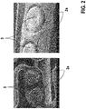
EP 2 457 601 Kompositröntgenmarker verwendet, bei denen es sich um Materialkombinationen von metallischen Markerpartikeln und polymeren Klebstoffen handelt. Der Masseanteil von röntgenabsorbierenden Partikeln im Komposit bestimmt maßgeblich die Röntgensichtbarkeit. Allerdings kann deren Anteil nicht wesentlich höher als 90 Gew.% sein. Bei höheren Anteilen wird das Gemisch bereits im nicht ausgehärteten Zustand so hoch viskos, dass eine Verarbeitung wie z. B. Injektion in Aufnahmen (sogenannte Eyelets) des Gerüsts nicht mehr möglich ist. Da aufgrund der Dichteunterschiede zwischen polymeren Klebstoffen (Rho < 2 g/cm3) und röntgenabsorbierenden Metallen wie Ta (Rho > 16 g/cm3) sich die Volumenverhältnisse genau konträr zu den jeweiligen Masseverhältnissen darstellen, gestaltet sich eine weitere Optimierung dieser Technologie schwierig. Selbst wenn es gelingen sollte, 95 Gew.% an röntgenabsorbierenden Partikeln in ein polymerhaltiges Komposit einzubringen und dieses auch definiert in ein Eyelet einzubringen, könnte trotzdem - aufgrund der sich dann einstellenden Dichte des Komposites - nur die Hälfte des jeweiligen Röntgenabsorptionspotentials genutzt werden, wie in derFigur 1 dargestellt ist. Dies führt besonders im Hinblick der Realisierung geringerer Wandstärken zu einer verminderten, nicht mehr relevanten Röntgensichtbarkeit. Weiterhin ist aus dem Stand der Technik die einfache Verklebung von Festkörpermarkern in die Eyelets von absorbierbaren Gerüsten (auch Scaffolds genannt) bekannt. Eine derartige Verklebung verhindert jedoch nur dann die Bildung von korrosionsbeschleunigenden Lokalelementen, wenn der Klebstoff eine permanente örtliche Trennung zwischen Marker und Scaffold während des gesamten Degradationsverlaufs sicherstellt. Dies ist regelmäßig nicht der Fall, wie z. B. in derFigur 2 dargestellt ist. Danach kann der Klebespalt 2a (ca. 20 Mikrometer) eines verwendeten Silikonklebstoffs technologisch bedingt nicht gleichmäßig über den Umfang verteilt werden. Nach der Verbringung in den Patienten, einer Dilatation und einer Verweilzeit des Gerüsts in der Gefäßumgebung von einigen Tagen bis Wochen bewirken Degradationseffekte eine Verschiebung des Röntgenmarkers 5 im jeweiligen Eyelet. Dies führt zumindest zum punktförmigen oder auch flächenhaften metallischen Direktkontakt zwischen Marker 5 und dem umgebenden Bulkmaterial des Gerüsts. Eine lokal erhöhte, rasch fortschreitende Korrosion der Markerumgebung ist die Folge. Dieser Effekt ist unbedingt zu vermeiden. - Weiterhin wird zur Verminderung des Korrosionsrisikos im Stand der Technik (z. B.
EP 2 399 619 ) vorgeschlagen, einen Festkörperröntgenmarker mit Fremdmetallen zu ummanteln. Bei diesen Varianten wird zwar die Gefahr der Lokalelementbildung bzw. Korrosion wesentlich reduziert, allerdings ist auch hier der technologische Herstellungsaufwand sehr hoch. - Weiterhin sind aus der
EP 1 973 502 mittels Form- und Kraftschluss in die Eyelets von polymeren Scaffolds eingebrachte Röntgenmarker bekannt, wobei nachträglich Lücken zwischen Marker und Scaffold mittels eines polymeren Materials verfüllt werden. - Hiervon ausgehend liegt der vorliegenden Erfindung die Aufgabe zugrunde, ein medizinisches Implantat sowie ein entsprechendes Verfahren zur Herstellung des Implantats bereitzustellen, das die Korrosionsgefahr aufgrund einer Zusammenwirkung des Gerüsts mit dem Röntgenmarker (insbesondere in einer wässrigen Umgebung) deutlich vermindert.
- Diese Aufgabe wird durch ein Implantat mit den Merkmalen des Anspruchs 1 sowie durch ein Verfahren mit den Merkmalen des Anspruchs 10 gelöst. Vorteilhafte Ausführungsformen dieser Aspekte der Erfindung sind in den entsprechenden Unteransprüchen angegeben und werden nachfolgend beschrieben.
- Gemäß Anspruch 1 wird ein medizinisches Implantat vorgeschlagen, mit:
- einem Gerüst, das zumindest eine Aufnahme für einen Röntgenmarker aufweist, wobei das Gerüst ein erstes Metall aufweist,
- zumindest einem in der Aufnahme angeordneten (vorzugsweise monolithischen) Röntgenmarker, wobei der Röntgenmarker ein zweites Metall aufweist,
- wobei erfindungsgemäß vorgesehen ist, dass der Röntgenmarker ein zweites Metall aufweist, und wobei auf den Röntgenmarker zum Verhindern eines korrosionsfördernden Kontakts zwischen dem Röntgenmarker und dem Gerüst eine elektrisch isolierende Beschichtung aufgebracht ist.
- Bevorzugt ist der Röntgenmarker monolithisch aufgebaut, d. h., er weist einen zusammenhängenden Grundkörper auf und besteht in diesem Fall nicht aus einer Vielzahl an Markerpartikeln, die durch einen separaten Klebstoff zusammengehalten werden.
- Bei dem Gerüst handelt es sich bevorzugt um ein Stentgerüst, das z. B. dazu eingerichtet und vorgesehen ist, in ein Blutgefäß eines Patienten implantiert zu werden. Das Stentgerüst weist dabei eine Vielzahl miteinander verbundener Streben auf, die die Zellen des Stentgerüstes bilden. Das Stentgerüst weist dabei zwei Enden auf, die eine Einlass- bzw. Auslassöffnung des Stentgerüstes umgeben, durch die Blut in einen vom Stentgerüst umgebenen Innenraum des Stentgerüstes einströmen bzw. wieder ausströmen kann. Die besagte Auf nahme ist bevorzugt als Durchgangsöffnung einer Strebe des Gerüsts bzw. Stentgerüstes ausgebildet, die bevorzugt an einem der Enden angeordnet ist. Bevorzugt sind an einer solchen Strebe zwei benachbarte Aufnahmen vorgesehen, die jeweils als Durchgangsöffnung ausgebildet sind und in die jeweils ein erfindungsgemäßer Röntgenmarker eingebracht wird. Bevorzugt sind zwei derartig benachbarte Aufnahmen, die auch als Eyelets bezeichnet werden, an beiden Enden des Stentgerüstes vorgesehen. Auf diese Weise kann mittels der Röntgenmarker, die dazu konfiguriert sind, in einer Röntgenaufnahme einen deutlichen Kontrast zu erzeugen, die genaue Raumlage und Position des Stents ermittelt werden. Ein Eyelet kann dabei erfindungsgemäß jede für die entsprechende Anwendung benötigte Form annehmen, beispielsweise rund, oval, trapezförmig oder quadratisch. Insbesondere besitzt das Eyelet eine Größe von 10 bis 1000 µm, von 10 bis 100 µm und von 20 bis 200 µm.
- Gemäß einer Ausführungsform des erfindungsgemäßen Implantats ist vorgesehen, dass die Beschichtung derart quellfähig ausgebildet ist, dass sie bei Kontakt mit einem Wasser enthaltenden Medium eine Volumenzunahme erfährt und dabei den Röntgenmarker zur Vermeidung des besagten Kontakts vom Gerüst beabstandet.
- Weiterhin ist gemäß einer Ausführungsform des erfindungsgemäßen Implantats vorgesehen, dass der Röntgenmarker eine Oberfläche mit einer Porenstruktur aufweist, wobei der Porendurchmesser bevorzugt im Bereich von 0,5 Mikrometer bis 3 Mikrometer liegt, oder dass der Kern eine Oberflächenstruktur aufweist, die bevorzugt einen Oberflächenrauheitswert Ra im Bereich von 0,5 Mikrometer bis 3 Mikrometer aufweist.
- Weiterhin ist gemäß einer Ausführungsform des erfindungsgemäßen Implantats vorgesehen, dass die Oberfläche zur Herstellung der Porenstruktur plasmachemisch oxidiert wird oder per Beaufschlagung mit Mikrostrahlen mechanisch bearbeitet wird.
- Weiterhin ist gemäß einer Ausführungsform des erfindungsgemäßen Implantats vorgesehen, dass die Beschichtung in den Poren oder in der Oberflächenstruktur aufgenommen ist und dazu ausgebildet ist, bei einem Kontakt mit einem Wasser enthaltenden Medium aus den Poren oder der Oberflächenstruktur herauszutreten, so dass bevorzugt eine Zentrierung des Röntgenmarkers in der Aufnahme sowie insbesondere eine Selbstpassivierung des Röntgenmarkers erfolgt.
- Weiterhin ist gemäß einer Ausführungsform des erfindungsgemäßen Implantats vorgesehen, dass der Röntgenmarker in der Aufnahme festgeklebt ist. Hierzu kann ein separater Klebstoff verwendet werden oder die besagte Beschichtung bildet selbst den notwendigen Klebstoff.
- Weiterhin ist gemäß einer Ausführungsform des erfindungsgemäßen Implantats vorgesehen, dass das zweite Metall eines der folgenden Metalle ist: Wolfram, Tantal, Gold, Platin, Iridium.
- Weiterhin ist gemäß einer Ausführungsform des erfindungsgemäßen Implantats vorgesehen, dass das Gerüst ein degradierbares Gerüst ist, das dazu ausgebildet ist, sich nach einer Implantation in einen menschlichen oder tierischen Körper innerhalb einer vordefinierbaren Zeitspanne vollständig aufzulösen.
- Weiterhin ist gemäß einer Ausführungsform des erfindungsgemäßen Implantats vorgesehen, dass das erste Metall Magnesium ist, wobei das Magnesium Bestandteil einer Magnesiumlegierung ist, die das Gerüst aufweist oder aus der das Gerüst besteht.
- Weiterhin ist gemäß einer Ausführungsform des erfindungsgemäßen Implantats vorgesehen, dass die Beschichtung einen oder mehrere der folgenden Stoffe aufweist: ein Polymer, insbesondere ein möglicherweise quellfähiges, unlösliches, vernetztes Polymer wie u. a. Polyacrylate, Polyacrylsäure (PAA), Polylaurinsäurevinylester, Polyvinylimidazol, Polyvinylpyrrolidon, Polyglycolsäure (PGA), Polyethylenglykol (PEG), Hyaluronsäure (HA), Polyharnstoffe, Polyurethane, Wasserglas, Cyanacrylat, Paraffin in Kombination mit einem geeigneten Vernetzer und ggf. einem geeigneten Lösungsmittel.
- Weiterhin wird die erfindungsgemäße Aufgabe durch ein Verfahren zur Herstellung eines medizinischen Implantats mit den Merkmalen des Anspruchs 10 gelöst, wobei ein Gerüst bereitgestellt wird, das zumindest eine Aufnahme für einen Röntgenmarker aufweist, wobei das Gerüst ein erstes Metall aufweist, und wobei ein, ein zweites Metall aufweisender Röntgenmarker bereitgestellt wird, auf den eine elektrisch isolierende Beschichtung aufgebracht wird, und wobei der beschichtete Röntgenmarker in der Aufnahme festgeklebt wird.
- Das Gerüst bzw. der Röntgenmarker können die weiter oben bzw. die in den Ausführungsbeispielen beschriebenen Merkmale aufweisen.
- Gemäß einer Ausführungsform des erfindungsgemäßen Verfahrens ist vorgesehen, dass der Röntgenmarker durch eine Behandlung der Oberfläche des Röntgenmarkers eine Poren- oder Oberflächenstruktur erhält.
- Weiterhin ist gemäß einer Ausführungsform des erfindungsgemäßen Implantats vorgesehen, dass der Röntgenmarker zum Aufbringen der Beschichtung mit einer Beschichtungslösung kontaktiert wird.
- Weiterhin ist gemäß einer Ausführungsform des erfindungsgemäßen Implantats vorgesehen, dass diese Beschichtungslösung ein Hydrogelmonomer, einen Vernetzer, einen Polymerisationsinitiator und einen Polymerisationskatalysator aufweist.
- Gemäß einer Ausführungsform der Erfindung können als Hydrogelmonomer Monomere wie beispielsweise Acrylate, Laurinsäurevinylester, Vinylimidazol, Vinylpyrrolidon, Diisocyanate u. a. zum Einsatz kommen, bevorzugt vinyloge Monomere. Weiterhin können gemäß einer Ausführungsform der Erfindung Vernetzer in Form von N,N'-Methylen-bis(acrylamid) (MBAA), Glutardialdehyd, 1-Ethyl-3-(3-dimethylaminopropyl)-carbodiimid/ N-Hydroxysuccinimid (EDC/NHS) oder andere verwendet werden.
- Weiterhin kann gemäß einer Ausführungsform Tetramethylethylendiamin (TEMED) als Polymerisationskatalysator verwendet werden.
- Weiterhin können gemäß einer Ausführungsform als Polymerisationsinitiator Ammoniumpersulfat (APS) oder Azobis(isobutyronitril) (AIBN) verwendet werden
- Gemäß einer Ausführungsform ist weiterhin vorgesehen, dass die Polymerisation auf der Oberfläche des Röntgenmarkers thermisch oder photochemisch aktiviert werden kann.
- Weiterhin kann die Polymerisation ergänzend gemäß einer Ausführungsform katalytisch unterstützt werden, z. B. durch eine entsprechende Zusammensetzung der Oberfläche des Röntgenmarkers, die z. B. durch eine amorphe Oxidschicht gebildet sein kann (z. B. WO3 oder Natriumwolframat als Schichtbestandteil).
- Gemäß einer Ausführungsform ist weiterhin bevorzugt vorgesehen, dass der beschichtete Röntgenmarker in die zugeordnete Aufnahme des Gerüsts geklebt wird. Hierbei kann als Klebstoff z. B. ein Silikon aufweisender Klebstoff verwendet werden.
- Weiterhin ist gemäß einer alternativen Ausführungsform des erfindungsgemäßen Implantats vorgesehen, dass die Beschichtungslösung ein quellfähiges Polymer aufweist, wobei die Beschichtungslösung weiterhin insbesondere einen Klebstoff aufweist.
- Gemäß einer Ausführungsform kann die Beschichtungslösung ein Polymer bzw. einen gelösten Superabsorber wie z. B. Polyacrylsäure (PAA), Polyglycolsäure (PGA), Polyethylenglykol (PEG), Hyaluronsäure (HA) oder andere derartige Stoffe aufweisen. Weiterhin kann die Beschichtungslösung neben einem oder mehreren dieser oder anderer geeigneter Polymere ELA-NCO oder Wasserglas oder ein Cyanacrylat, oder verdünnte wässrige oder lösungsmittelhaltige Gemische (z. B. eine chloroformhaltige Paraffinlösung) aufweisen. Paraffin oder Wasserglas sind mit Vorteil elektrisch isolierend und inert.
- Gemäß einer Ausführungsform der Erfindung wird die Beschichtungslösung mit dem quellfähigen Polymer gleichzeitig als Klebstoff verwendet, d.h. der Röntgenmarker wird gemäß einer Ausführungsform mittels der Beschichtungslösung auch direkt ohne Zusatz eines (Silikon)klebstoffes mit der Aufnahme verklebt.
- Weiterhin ist gemäß einer Ausführungsform des erfindungsgemäßen Implantats vorgesehen, dass der Röntgenmarker in der Aufnahme festgeklebt wird, wobei vorzugsweise ein hierzu verwendeter Klebstoff durch die Beschichtung bzw. die Beschichtungslösung gebildet wird.
- Generell sind das entstehende quellfähige Polymergel (Hydrogel) oder der quellfähige Kleberersatz vorzugsweise biokompatibel und quellen bei Anwesenheit von wässrigen (auch Chlorid haltigen) Lösungen beziehungsweise Blut auf.
- Zusammenfassend ermöglicht die vorliegende Erfindung durch die quellfähige, elektrisch isolierende Beschichtung die Verwendung von Solidröntgenmarkern (monolithische Röntgenmarker), deren bisherige Anwendung bei degradierbaren Scaffold- bzw. Gerüstmaterialien, wie Magnesiumlegierungen, erhöhte Korrosionsraten und daraus resultierend eine erheblich verkürzte Standzeit zur Folge hatte. Die Gefahr der unbeabsichtigt und plötzlich auftretenden Bildung von Lokalelementen während der klinisch relevanten Stützzeit und die daraus resultierende nicht kalkulierbare Korrosion mit verstärkter lokaler Wasserstoffbildung und damit verbundener möglicher unerwünschter biologischer Reaktionen tritt nicht mehr auf bzw. wird deutlich unterdrückt.
- Der bevorzugte, erfindungsgemäße Quellungseffekt bewirkt eine wesentliche Volumenvergrößerung der Beschichtung in dessen Folge das Polymer/Hydrogel aus der porösen bzw. strukturierten Oberfläche des Röntgenmarkers heraustritt.
- Beim Auftreffen des Polymers auf die Wandung der mindestens einen Aufnahme bzw. Eyelets wird einerseits der Quelleffekt in andere Richtungen umgelenkt, andererseits findet im Klebespalt (z. B. ca. 20 µm) eine Selbstzentrierung des Röntgenmarkers in der Aufnahme statt und verhindert den Metall-Metall-Kontakt zwischen dem ersten und dem zweiten Metall. Die korrosive Umgebung selbst bewirkt damit insbesondere eine Selbstpassivierung. Der Degradationsverlauf bis zur völligen Umwandlung des Gerüsts in seine Korrosionsprodukte wird nicht unterbrochen.
- Die Erfindung ermöglicht letztlich eine Vereinfachung des Markermontageprozesses, da eine Erhöhung der Fertigungstoleranzen möglich ist. Durch die nachträgliche Quellung kommt es insbesondere zur Selbstzentrierung des Röntgenmarkers, wodurch auch unvollständig zentrierte Röntgenmarker akzeptiert werden können.
- Weitere Merkmale und Vorteile der Erfindung sollen bei der Figurenbeschreibung von Ausführungsbeispielen der Erfindung anhand der Figuren erläutert werden. Es zeigen:
- Fig. 1
- eine Darstellung der sich ergebenden Kompositdichte als Funktion des Metallanteils. Die senkrechte Linie stellt den maximalen Metallanteil dar, der als Komposit derzeit technologisch herstellbar ist;
- Fig. 2
- einen eingeklebter Solidmarker mit ungleichmäßig gefülltem Klebespalt;
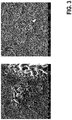
- Fig. 3
- eine poröse plasmachemisch oxidierte Oberfläche eines Röntgenmarkers aus (links) Tantal und (rechts) Wolfram;
- Fig. 4
- eine Ansicht eines erfindungsgemäßen Implantats mit benachbarten Aufnahmen (Eyelets) für Röntgenmarker; und
- Fig. 5
- eine schematische Ansicht eines erfindungsgemäßen Eyelets.
- Die
Figur 4 zeigt im Zusammenhang mit derFigur 5 ein erfindungsgemäßes medizinisches Implantat, mit einem Gerüst 1, das zumindest eine Aufnahme 2 für einen Röntgenmarker 5 aufweist, - Bei dem Gerüst 1 handelt es sich insbesondere gemäß
Figur 4 um ein Stentgerüst, das z. B. dazu eingerichtet und vorgesehen ist, in ein Blutgefäß eines Patienten implantiert zu werden. Das Stentgerüst 1 weist dabei eine Vielzahl miteinander verbundener Streben 101 auf, die Zellen des Stentgerüstes 1 bilden. Das Stentgerüst weist dabei zwei Enden 102 auf (in derFigur 4 ist nur ein Ende gezeigt), die eine Einlass- bzw. Auslassöffnung des Stentgerüstes 1 umgeben, durch die Blut in einen vom Stentgerüst 1 umgebenen Innenraum 103 des Stentgerüstes 1 einströmen bzw. wieder ausströmen kann. Die besagte mindestens eine Aufnahme 2 ist bevorzugt als Durchgangsöffnung einer Strebe 101 des Gerüsts bzw. Stentgerüstes 1 ausgebildet. GemäßFigur 4 sind z. B. zwei benachbarte Aufnahmen 2 bzw. Eyelets 2 an einem der Enden 102 oder an beiden Enden 102 angeordnet. - Sind die Röntgenmarker 5 in der jeweiligen Aufnahme 2 angeordnet, wird ein umlaufender Klebespalt 2a definiert, der schematisch in der
Figur 5 gezeigt ist. - Das Gerüst 1 weist ein erstes Metall auf, vorzugsweise Magnesium, das in einer das Gerüst 1 bildenden Magnesiumlegierung vorliegt, die z. B. eine Zusammensetzung aufweisen kann, wie sie in
DE 101 18 603 A1 beschrieben ist, und zumindest einen in der Aufnahme 2 angeordneten Röntgenmarker 5. Der mindestens eine Röntgenmarker 5 bzw. die mehreren Marker 5, der bzw. die in der jeweiligen Aufnahme 2 angeordnet ist bzw. sind, weisen weiterhin ein zweites Metall auf, das eines der hierin beschriebenen Metalle sein kann (siehe oben sowie Ausführungsbeispiele weiter unten). - Unter Magnesiumlegierung wird hier ein metallisches Gefüge verstanden, dessen Hauptkomponente Magnesium ist. Hauptkomponente ist die Legierungskomponente, deren Gewichtsanteil an der Legierung am höchsten ist. Ein Anteil der Hauptkomponente beträgt vorzugsweise mehr als 50 Gew.%, insbesondere mehr als 70 Gew.%, ganz besonders bevorzugt mehr als 90 Gew.%. Vorzugsweise enthält die biokorrodierbare Magnesiumlegierung des Kerns Yttrium und weitere Seltenerdmetalle, da sich eine derartige Legierung aufgrund ihrer physiko-chemischen Eigenschaften und hohen Biokompatibilität, insbesondere auch seiner Abbauprodukte, auszeichnet. Unter der Sammelbezeichnung "Seltenerdmetalle" werden vorliegend Scandium (21), Yttrium (39), Lanthan (57) und die 14 auf Lanthan (57) folgenden Elemente, nämlich Cer (58), Praseodym (59), Neodym (60), Promethium (61), Samarium (62), Europium (63), Gadolinium (64), Terbium (65), Dysprosium (66), Holmium (67), Erbium (68), Thulium (69), Ytterbium (70) und Lutetium (71) verstanden. Dem Fachmann ist eine Vielzahl von Magnesiumlegierungen bekannt. Besonders bevorzugt ist eine Magnesiumlegierung der Zusammensetzung Seltenerdmetalle 5,2 - 9,9 Gew.%, davon Yttrium 3,7 - 5,5 Gew.%, und Rest < 1 Gew.%, wobei Magnesium den auf 100 Gew.% fehlenden Anteil an der Legierung einnimmt. Insbesondere bevorzugt ist eine Magnesiumlegierung der Zusammensetzung Yttrium 3,7 - 5,5 Gew.%, Neodym 1,5 - 3 Gew.%, Zirkonium 0,3 - 1 Gew.%, Gadolinium 0,4 - 0,55 Gew.%, Dysprosium 0,4 - 0,55 Gew.%, Eisen <0,006 und Rest < 1 Gew.%, wobei Magnesium den auf 100 Gew.% fehlenden Anteil an der Legierung einnimmt. Weiterhin bevorzugt sind Legierungen auf Basis von Magnesium der Form Mg-Zn-Al, Mg-Zn-Ca, Mg-Zn oder Mg-Al, wobei diese Legierungen höchstens Spuren von Seltenerdmetalle oder weiteren Elementen aufweisen. Bevorzugt ist eine Magnesiumlegierung der Zusammensetzung Zink 1,5 -7,0 Gew.%, Aluminium 0,5 - 10,0 Gew.%, Rest < 0,0063 Gew.%, wobei Magnesium den auf 100 Gew.% fehlenden Anteil an der Legierung einnimmt. Weiterhin bevorzugt ist eine Magnesiumlegierung der Zusammensetzung Zink 3,0 - 7,0 Gew.%, Kalzium 0,001 - 0,6 Gew.%, Rest < 0,0048 Gew.%, wobei Magnesium den auf 100 Gew.% fehlenden Anteil an der Legierung einnimmt. Weiterhin bevorzugt ist eine Magnesiumlegierung der Zusammensetzung Aluminium 1,0 - 10,0 Gew.%, Rest < 0,0048 Gew.%, wobei Magnesium den auf 100 Gew.% fehlenden Anteil an der Legierung einnimmt.
- Erfindungsgemäß ist nun vorgesehen, dass der mindestens eine Röntgenmarker 5 zum Verhindern des eingangs beschriebenen korrosionsfördernden Kontakts zwischen dem zweiten Metall des mindestens einen Röntgenmarkers 5 und dem ersten Metall (bzw. weiteren Metallen) des Gerüsts 1 eine elektrisch isolierende Beschichtung 3 aufweist, die besonders bevorzugt quellfähig ausgebildet ist, so dass sie bei einem Kontakt mit einem Wasser enthaltenden Medium (insbesondere bei Blutkontakt nach einer Implantation) eine Volumenzunahme erfährt.
- Diese Quellung bei Kontakt mit dem besagten Medium bewirkt einerseits eine Zentrierung des Röntgenmarkers in der Aufnahme sowie eine entsprechende Beabstandung von einem Rand der Aufnahme, so dass ein gleichmäßiger Klebespalt 2a resultiert. Des Weiteren bewirkt die Volumenzunahme gewissermaßen eine Selbstpassivierung des Markers 5 bei Kontakt mit dem besagten wässrigen Medium. Da dieser durch die Volumenzunahme der Beschichtung wirksam (Korrosion vermeidend) abgeschirmt wird.
- Zur besseren Anhaftung der Beschichtung 3 ist bevorzugt vorgesehen, dass die Oberfläche 4 des mindestens einen Röntgenmarkes 5 eine Oberflächenaufrauhung erhält, indem der Solidmarker 5 aus W (oder Ta) gefertigt wird und plasmachemisch oxidiert wird (siehe
Figur 3 ) oder als Edelmetallmarker 5 (aus Au oder Pt) ausgebildet wird, der per Mikrostrahlen mechanisch behandelt wird. Die bereits vorhandene, natürliche kristalline Oxidschicht (wenige nm dick) bei W und Ta wird hierbei durch eine amorphe Oxidschicht (mehrere µm dick) ersetzt. Wolfram- und Tantal-Marker 5 besitzen danach eine Porenstruktur mit Porendurchmessern zwischen 0,5 und 3 µm, die Porentiefe ist insbesondere etwas kleiner als die Schichtdicke. Die Edelmetallmarker 5 weisen weiterhin Oberflächenrauheitswerte zwischen Ra 0,5 und 3 µm auf - Die so behandelten Marker 5 mit einem Durchmesser von z. B. ca. 320 µm werden gemäß einem ersten Beispiel der Erfindung in eine Lösung zur quellfähigen Beschichtung getaucht.
- Durch Anlegen eines Unterdruck, beispielsweise mit Hilfe eines Exsikkators, von unter 200 mbar werden die Poren mit dem quellfähigen Polymer oder der dieses durch Polymerisation bildenden Monomerlösung gefüllt und die Luftblasen entfernt. Danach erfolgt eine Trocknung, Polymerisation (Aushärten an Luft oder thermisch aktiviert) oder sofortige Verklebung in das jeweilige Eyelet 2.
- Gemäß einem Beispiel der Erfindung besteht die Lösung zur quellfähigen Beschichtung aus:
- einer Additivlösung aus einem Hydrogelmonomer, Vernetzer, Initiator und Polymerisationskatalysator. Als Hydrogelmonomer werden bevorzugt vinyloge Monomere wie beispielsweise Laurinsäurevinylester, Vinylimidazol, Vinyl¬pyrrolidon, u.a. eingesetzt. Als Vernetzer können z. B. N,N'-Methylen¬bis(acrylamid) (MBAA), Glutardialdehyd, 1-Ethyl-3-(3-dimethyl¬aminopropyl)¬carbodiimid/ N-Hydroxy-succinimid (EDC/NHS) oder andere fungieren. Als Initiatoren können z. B. Ammoniumpersulfat (APS) oder Azo-bis(isobutyronitril) (AIBN) genutzt werden. Als Polymerisationskatalysator kann z. B. Tetramethylethylendiamin (TEMED) verwendet werden. Hierbei kann die Polymerisation auf der Markeroberfläche 4 thermisch oder photochemisch aktiviert werden oder katalytisch, durch die Zusammensetzung der amorphen Oxidschicht (z. B. WO3 oder Natriumwolframat als Schichtbestandteil) unterstützt werden. Eine nachträgliche Verklebung des so isolierten Markers 5 im Eyelet 2 erfolgt z. B. mit einem geeigneten Klebstoff.
- Gemäß einem alternativen Beispiel kann die Beschichtungslösung aus einem quellfähigen Polymer bestehen, das auch als Kleber eingesetzt werden kann und diesen ggf. ersetzt. Innerhalb dieses Haftgels wird ein quellfähiges Polymer mit einem Kleberersatzstoff kombiniert. Das Haftgel kann aus einem gelösten Superabsorber wie beispielsweise Polyacrylsäure (PAA), Polyglycolsäure (PGA), Polyethylenglykol (PEG), Hyaluronsäure (HA) oder anderen geeigneten Polymeren, und aus Polyharnstoffen oder Polyurethanen oder Wasserglas oder Cyanacrylaten oder verdünnten wässrigen oder lösungsmittelhaltigen Gemischen (z. B. chloroformhaltige Paraffinlösung) bestehen.
- Diese Lösung zur quellfähigen Beschichtung dient bevorzugt gleichzeitig als Kleber, wodurch der jeweilige Marker 5 ggf auch direkt ohne Zusatz eines Silikonklebstoffes im zugeordneten Eyelet 2 verklebt werden kann.
- Generell sind das entstehende quellfähige Polymergel (Hydrogel) oder der quellfähige Kleberersatz biokompatibel und quellen bei Anwesenheit von wässrigen (auch Chlorid haltigen) Lösungen beziehungsweise Blut auf.
- Gemäß einem weiteren Beispiel der Erfindung wurde ein Gerüst 1 mit einem Röntgenmarker 5 aus Wolfram bereitgestellt (vgl.
Figuren 4 und5 ), der eine mittels plasmachemischer Oxidation erzeugte makroporöse Oberfläche 4 aus Wolframoxid aufweist. - Das Gerüst 1 weist dabei eine degradierbare Magnesiumlegierung (vgl.
Fig. 4 ) auf, die jeweils am distalen und am proximalen Ende 102 ein Doppeleyelet 2 aufweist (d. h. zwei benachbarte Aufnahmen in Form von Durchgangsöffnungen 2 einer Strebe 101), das für eine Befüllung mit Röntgenmarkern 5 vorgesehen ist. Der Durchmesser eines Eyelets 2 beträgt z. B. ca. 350 µm. - In diese Eyelets 2 werden runde Massivmarker 5 aus Wolfram montiert. Die Dicke dieser Wolframmarker ist identisch mit der Wanddicke des Scaffolds 1 und beträgt beispielsweise 100 µm. Der Durchmesser ist ca. 20 µm geringer als der Eyeletdurchmesser. Der Wolframmarker 5 wurde vorher in einem Schwefel- und Phosphorsäure enthaltenden Elektrolyt plasmachemisch oxidiert. Die Oxidation des chemisch stabilen Elements Wolfram wird durch die bei Badspannungen > 180 V entstehenden lokal begrenzten Plasmaentladungen hervorgerufen. Dabei rastern einzelne Plasmaentladungen die Wolframoberfläche systematisch ab. Die Oberfläche des Markers 5 erhält dadurch eine verfahrenstypische poröse Oberfläche, die zum größten Teil aus WO3 besteht. Die Oxidschichtdicke beträgt zwischen 3 und 6 µm. Aufgrund des Konversionscharakters der Plasmaentladungen bleibt die ursprüngliche Außengeometrie des Markers 5 erhalten und die Oxidschicht weist aufgrund der stofflichen Verzahnung mit dem darunter liegenden metallischen Substrat eine hohe Haftfestigkeit auf (vgl.
Fig. 5 ). Diese Oberflächenstrukturierung führt auch zu einer wesentlichen Vergrößerung der realen Oberfläche mindestens um den Faktor 2. - Dies ist eine wesentliche Voraussetzung für eine hohe Benetzungsfähigkeit. Der so behandelte Marker 5 wird anschließend in eine Lösung zur quellfähigen Beschichtung getaucht, die z. B. gemäß einem der oben genannten Beispiele ausgeführt sein kann. Um die in der porösen Oberfläche 4 enthaltenden Luftblasen zu entfernen, erfolgt dieser Tauchprozess in einem Exsikkator, der mit Unterdruck < 200 mbar beaufschlagt wird. Nach einer Behandlungszeit zwischen 2 und 5 min ist der Entgasungsprozess abgeschlossen und es sind keine aufsteigenden Luftblasen mehr sichtbar. Die Markeroberfläche 4 ist mit dem quellfähigen Polymer 3 benetzt und wird aus der Beschichtungslösung entnommen. Gegebenenfalls erfolgt anschließend eine thermisch initiierte Polymerisation bei > 50°C, eine Lösungsmittelentfernung im Vakuumtrockenschrank oder eine direkte Verklebung im jeweiligen Eyelet 2.
Nach diesem Prozess wird der Marker 5 in das Eyelet 2 positioniert. Gegebenenfalls wurde die Eyeletumgebung vorher mit der zuvor (zum Beschichten des jeweiligen Markers 5) verwendeten Lösung zur quellfähigen Beschichtung belegt (siehe oben). Nach der Positionierung des jeweiligen Markers 5 im zugeordneten Eyelet 2 erfolgt die finale thermische Behandlung, die zu einer Polymerisation der Beschichtung auf der Röntgenmarkeroberfläche führt und eine ausreichende Haltekraft des Markers 5 im Eyelet 2 bewirkt. Danach erfolgt insbesondere die Montage des Scaffolds 1 in ein Kathetersystem. - Während der vaskulären Intervention des Scaffolds 1 kommt die Umgebung des Röntgenmarkers 5 in Kontakt mit Blut. Daraufhin setzt ein Quellprozess des polymeren Hydrogels 3 ein. Dieser führt zu einer Volumenvergrößerung und einem Heraustreten des Hydrogels 3 aus der Markeroberfläche 4. Dies trifft auch auf die Schnittkanten des Markers 5 zu. Dieser Selbstversiegelungseffekt stellt eine Verkapselung des Markers 5 und eine Isolation dessen zum übrigen Scaffold 1 dar. Zudem werden technologisch bedingte Unzulänglichkeiten beim Prozess der Markerpositionierung durch eine nachträgliche Selbstzentrierung des Markers 5 im Eyelet 2 ausgeglichen. Somit wird sichergestellt, dass kein Metall-/Metallkontakt entsteht, die Lokalelementbildung sicher unterbunden wird und keine Beeinflussung des weiteren Degradationsverlaufs des Scaffolds 1 stattfindet.
- Gemäß einem weiteren Beispiel der Erfindung wurde ein Scaffold 1 mit einem Röntgenmarker 5 aus Tantal bereitgestellt, der eine mittels plasmachemischer Oxidation erzeugte makroporöse Oberfläche 4 aus Tantaloxiden aufweist. Das verwendete Gerüst (Scaffold) 1 aus einer degradierbaren Magnesiumlegierung (vgl.
Figur 4 ) hat wiederum jeweils am distalen und am proximalen Ende 102 ein Doppeleyelet 2, das für eine Befüllung mit Röntgenmarkern 5 vorgesehen ist. Der Durchmesser eines Eyelets 2 beträgt z. B. ca. 350 µm. In diese Eyelets 2 werden runde Massivmarker 5 aus Tantal montiert. Die Dicke dieser Tantalmarker 5 ist identisch mit der Wanddicke des Scaffolds 1 und beträgt beispielsweise 100 µm. Der Durchmesser ist ca. 20 µm geringer als der Eyeletdurchmesser. Der jeweilige Tantalmarker 5 wurde vorher in einem Schwefel- und Phosphorsäure enthaltenden Elektrolyt plasmachemisch oxidiert. Die Oxidation des chemisch stabilen Elements Tantal wird durch die bei Badspannungen > 180 V entstehenden lokal begrenzten Plasmaentladungen hervorgerufen. Dabei rastern einzelne Plasmaentladungen die Tantaloberfläche systematisch ab. Die Oberfläche des Markers 5 erhält dadurch eine verfahrenstypische poröse Oberfläche 4, die zum größten Teil aus Tantalpentoxid Ta2O5 besteht. Die Oxidschichtdicke beträgt zwischen 3 und 6 µm. Aufgrund des Konversionscharakters der Plasmaentladungen bleibt die ursprüngliche Außengeometrie des Markers 5 erhalten und die Oxidschicht weist aufgrund der stofflichen Verzahnung mit dem darunter liegenden metallischen Substrat eine hohe Haftfestigkeit auf (vgl.Fig. 5 ). Diese Oberflächenstrukturierung 4 führt auch zu einer wesentlichen Vergrößerung der realen Oberfläche mindestens um den Faktor 2. Dies ist wiederum eine wesentliche Voraussetzung für eine hohe Benetzungsfähigkeit. - Der so behandelte Marker wird 5 anschließend in eine Beschichtungslösung getaucht, die einem der oben dargestellten Beispiele entsprechen kann. Um die in der porösen Oberfläche 4 enthaltenden Luftblasen zu entfernen, erfolgt dieser Tauchprozess wiederum in einem Exsikkator der mit einem Unterdruck < 200 mbar beaufschlagt wird. Nach einer Behandlungszeit zwischen 2 und 5 min ist der Entgasungsprozess abgeschlossen und es sind keine aufsteigenden Luftblasen mehr sichtbar. Die Markeroberfläche 4 ist mit dem quellfähigen Polymer 3 benetzt und wird aus der Beschichtungslösung entnommen. Gegebenenfalls erfolgt anschließend eine thermisch initiierte Polymerisation bei >50°C, eine Lösungsmittelentfernung im Vakuumtrockenschrank oder eine direkte Verklebung im jeweiligen Eyelet 2.
- Nach diesem Prozess wird der Marker 5 in dem Eyelet 2 positioniert. Ggf. wurde die Eyeletumgebung vorher mit der identischen (zuvor zum Beschichten des jeweiligen Ta-Markers 5) verwendeten Lösung zur quellfähigen Beschichtung belegt. Nach der Positionierung des jeweiligen Markers 5 im zugeordneten Eyelet 2 erfolgt die finale thermische Behandlung, die zu einer Polymerisation der Beschichtung auf der Röntgenmarkeroberfläche führt und eine ausreichende Haltekraft des Markers 5 im Eyelet 2 bewirkt. Danach erfolgt die Montage des Scaffolds 1 im Kathetersystem.
- Gemäß einem weiteren Beispiel der Erfindung wurde ein Scaffold 1 mit einem Röntgenmarker 5 aus Gold (Au) bereitgestellt, der eine mittels Mikrostrahlen aufgeraute makroporöse Oberfläche 4 aufweist. Dieses Gerüst 1 besteht wiederum gemäß
Fig. 4 aus einer degradierbaren Magnesiumlegierung und weist jeweils am distalen und am proximalen Ende 102 ein Doppeleyelet 2 auf, das für eine Befüllung mit Röntgenmarkern 5 vorgesehen ist. Der Durchmesser eines Eyelets 2 beträgt z. B. ca. 350 µm. In diese Eyelets 2 werden runde Massivmarker 5 aus Gold montiert. Die Dicke dieser Goldmarker ist identisch mit der Wanddicke des Scaffolds 1 und beträgt beispielsweise 100 µm. Der Durchmesser ist ca. 20 µm geringer als der Eyeletdurchmesser. Der Goldmarker 5 wurde vorher mittels Mikrostrahlen mit Korundkörnern aufgeraut. Die dabei erzielte Oberflächenrauheit beträgt zwischen Ra 0,5 µm und Ra 3,0 µm. Die Oberfläche des Markers 5 erhält dadurch eine mikroraue poröse Oberfläche 4. Diese Oberflächenstrukturierung führt auch zu einer wesentlichen Vergrößerung der realen Oberfläche mindestens um den Faktor 2. Dies ist eine wesentliche Voraussetzung für eine hohe Benetzungsfähigkeit. - Der so behandelte Marker wird anschließend in eine Lösung zur quellfähigen Beschichtung getaucht, die gemäß einem der oben genannten Beispiele ausgebildet sein kann. Um die in der porösen Oberfläche 4 enthaltenden Luftblasen zu entfernen erfolgt dieser Tauchprozess wiederum bevorzugt in einem Exsikkator der mit Unterdruck < 200 mbar beaufschlagt wird. Nach einer Behandlungszeit zwischen 2 und 5 min ist der Entgasungsprozess abgeschlossen und es sind keine aufsteigenden Luftblasen mehr sichtbar. Die Markeroberfläche 4 ist mit dem quellfähigen Polymer 3 benetzt und wird aus der Beschichtungslösung entnommen. Gegebenenfalls erfolgt anschließend eine thermisch initiierte Polymerisation bei > 50°C, eine Lösungsmittelentfernung im Vakuumtrockenschrank oder eine direkte Verklebung im jeweiligen Eyelet 2.
- Nach diesem Prozess wird der jeweilige Marker im entsprechenden Eyelet 2 positioniert. Ggf. wurde die Eyeletumgebung vorher mit der identischen Lösung zur quellfähigen Beschichtung, die zuvor zum Beschichten der Marker 5 verwendet wurde, belegt. Nach der Positionierung des jeweiligen Markers 5 im zugeordneten Eyelet 2 erfolgt die finale thermische Behandlung, die zu einer Polymerisation des Werkstoffverbundes führt und eine ausreichende Haltekraft der Marker 5 in den Eyelets 2 bewirkt. Danach erfolgt wiederum die Montage des Scaffolds 1 im Kathetersystem.
- Gemäß einem weiteren Beispiel der Erfindung wurde ein Scaffold 1 mit einem Röntgenmarker 5 aus Platin (Pt) bereitgestellt, der eine mittels Mikrostrahlen aufgeraute makroporöse Oberfläche 4 aufweist. Dieses Gerüst 1 besteht wiederum aus einer degradierbaren Magnesiumlegierung (vgl.
Fig. 4 ) und weist jeweils am distalen und am proximalen Ende 102 ein Doppeleyelet 2 auf, das für eine Befüllung mit Röntgenmarkern 5 vorgesehen ist. Der Durchmesser eines Eyelets 2 beträgt z. B. ca. 350 µm. In diese Eyelets 2 werden runde Massivmarker 5 aus Platin montiert. Die Dicke dieser Platinmarker 5 ist identisch mit der Wanddicke des Scaffolds 1 und beträgt beispielsweise 100 µm. Der Durchmesser ist ca. 20 µm geringer als der Eyeletdurchmesser. Der jeweilige Platinmarker 5 wurde vorher mittels Mikrostrahlen mit Korundkörnern aufgerauht. Die dabei erzielte Oberflächenrauheit beträgt zwischen Ra 0,5 µm und Ra 3,0 µm. Die Oberfläche 4 des jeweiligen Markers 5 erhält dadurch eine mikrorauhe poröse Oberfläche 4. Diese Oberflächenstrukturierung führt auch zu einer wesentlichen Vergrößerung der realen Oberfläche mindestens um den Faktor 2. Dies ist eine wesentliche Voraussetzung für eine hohe Benetzungsfähigkeit. - Der so behandelte jeweilige Marker 5 wird anschließend in eine Lösung zur quellfähigen Beschichtung getaucht, die gemäß einem der obigen Beispiele ausgeführt ist. Um die in der porösen Oberfläche 4 enthaltenden Luftblasen zu entfernen, erfolgt dieser Tauchprozess in einem Exsikkator der mit Unterdruck < 200 mbar beaufschlagt wird. Nach einer Behandlungszeit zwischen 2 und 5 min ist der Entgasungsprozess abgeschlossen und es sind keine aufsteigenden Luftblasen mehr sichtbar. Die Markeroberfläche 5 ist mit dem quellfähigen Polymer 3 benetzt und wird aus der Beschichtungslösung entnommen. Gegebenenfalls erfolgt anschließend eine thermisch initiierte Polymerisation bei > 50°C, eine Lösungsmittelentfernung im Vakuumtrockenschrank oder eine direkte Verklebung im jeweiligen Eyelet 2.
- Nach diesem Prozess wird der jeweilige Marker im betreffenden Eyelet 2 positioniert. Ggf. wurde die Eyeletumgebung vorher mit der zuvor zum Beschichten der Marker 5 verwendeten identischen Lösung zur quellfähigen Beschichtung belegt. Nach der Positionierung des jeweiligen Markers 5 im zugeordneten Eyelet 2 erfolgt die finale thermische Behandlung, die zu einer Polymerisation der Beschichtung auf der Röntgenmarkeroberfläche führt und eine ausreichende Haltekraft des jeweiligen Markers im zugeordneten Eyelet 2 bewirkt. Danach erfolgt wiederum die Montage des Scaffolds 1 im Kathetersystem.
- Gemäß einem weiteren Beispiel der Erfindung wird ein Scaffold 1 mit einem Röntgenmarker 5 aus einem röntgenabsorbierenden Metall wie z. B. Pt, Au, W, Ta, oder Ir vorgeschlagen, der eine dünne silikatische und damit nichtleitende Oberfläche 4 aufweist.
- Diese silikatische Oberfläche 4 wird durch Eintauchen von Drähten aus Röntgenmarkermaterialien in verdünnte Wasserglaslösungen und anschließende Lufttrocknung erzielt. Dabei bilden sich in Abhängigkeit des Verdünnungsgrades des Wasserglases ca. 1 µm bis 10 µm dicke und elektrisch isolierende Schichten auf den Drahtoberflächen. Die Zusammensetzung dieser Schichten entspricht der Formel M2O * nSiO2. Dabei kann M aus den Elementen Li, Na oder K bestehen. Die Verwendung von Li-haltigen Wasserglaslösungen bietet den Vorteil, dass die entstehenden Schichten nach dem Trocknungsprozess eine geringere Neigung zur Rissbildung aufweisen. Die so behandelten Drähte werden danach (z. B. mit dem Microtom oder mit einer mit mikrokristallinen Diamantkörnern besetzten Drahtsäge) in ca. 100 µm dünne Abschnitte getrennt und wie in einem der oben genannten Beispiele weiter behandelt um zu einem Gerüst 1 mit einem beschichteten Röntgenmarker 5 zu gelangen.
- Die Technologie des Trennens mit dem Microtom oder der Diamantdrahtsäge stellt sicher, dass saubere und verwerfungsfreie Schnittkanten entstehen und die Silikatschicht nicht splittert. Diese Herangehensweise allein stellt sowohl eine Alternative zum Einsatz von quellfähigen Polymeren dar und kann andererseits aber auch in Kombination mit diesen zum Einsatz gebracht werden. Das bedeutet, dass die silikathaltigen Oberflächen 4 der Röntgenmarker 5 selbst dann keine korrosionsfördernde Lokalelementwirkung entfalten, wenn der Klebespalt keinen oder nicht genügend Klebstoff enthält.
- Im Ergebnis ermöglicht die Erfindung mit Vorteil eine Vermeidung der Gefahr einer unbeabsichtigt und plötzlich auftretenden Bildung von Lokalelementen während der klinisch relevanten Stützzeit des Gerüsts und die daraus resultierende nicht kalkulierbare Korrosion mit verstärkter lokaler Wasserstoffbildung und damit verbundener unerwünschter biologischer Reaktionen im Körper des Patienten.
Claims (15)
- Medizinisches Implantat, mit:- einem Gerüst (1), das zumindest eine Aufnahme (2) für einen Röntgenmarker (5) aufweist, wobei das Gerüst (1) ein erstes Metall aufweist,- zumindest einem in der Aufnahme (10) angeordneten Röntgenmarker (5), wobei der Röntgenmarker (5) ein zweites Metall aufweist,dadurch gekennzeichnet,
dass der Röntgenmarker (5) ein zweites Metall aufweist, und wobei auf den Röntgenmarker (5) zum Verhindern eines korrosionsfördernden Kontakts zwischen dem Röntgenmarker (5) und dem Gerüst (1) eine elektrisch isolierende Beschichtung (3) aufgebracht ist. - Medizinisches Implantat nach Anspruch 1, dadurch gekennzeichnet, dass die Beschichtung (3) derart quellfähig ausgebildet ist, dass sie bei einem Kontakt mit einem Wasser enthaltenden Medium eine Volumenzunahme erfährt.
- Medizinisches Implantat nach Anspruch 1 oder 2, dadurch gekennzeichnet, dass der Röntgenmarker (1) eine Oberfläche (4) mit einer Porenstruktur aufweist, wobei der Porendurchmesser bevorzugt im Bereich von 0,5 Mikrometer bis 3 Mikrometer liegt, oder dass der Röntgenmarker (1) eine Oberfläche (4) mit einer Oberflächenstruktur aufweist, die bevorzugt einen Oberflächenrauheitswert Ra im Bereich von 0,5 Mikrometer bis 3 Mikrometer aufweist.
- Medizinisches Implantat nach Anspruch 3, dadurch gekennzeichnet, dass die Beschichtung (3) in den Poren oder in der Oberflächenstruktur aufgenommen ist und dazu ausgebildet ist, bei einem Kontakt mit einem Wasser enthaltenden Medium aus den Poren oder der Oberflächenstruktur herauszutreten, so dass bevorzugt eine Zentrierung des Röntgenmarkers (5) in der Aufnahme (2) erfolgt.
- Medizinisches Implantat nach einem der vorhergehenden Ansprüche, dadurch gekennzeichnet, dass der Röntgenmarker (5) in der Aufnahme (2) festgeklebt ist.
- Medizinisches Implantat nach einem der vorhergehenden Ansprüche, dadurch gekennzeichnet, dass das zweite Metall eines der folgenden Metalle ist: Wolfram, Tantal, Gold, Platin, Iridium.
- Medizinisches Implantat nach einem der vorhergehenden Ansprüche, dadurch gekennzeichnet, dass das Gerüst (1) ein degradierbares Gerüst ist.
- Medizinisches Implantat nach einem der vorhergehenden Ansprüche, dadurch gekennzeichnet, dass das erste Metall Magnesium ist, wobei das Magnesium Bestandteil einer Magnesiumlegierung ist, die das Gerüst (1) aufweist oder aus der das Gerüst (1) besteht.
- Medizinisches Implantat nach einem der vorhergehenden Ansprüche, dadurch gekennzeichnet, dass die Beschichtung einen oder mehrere der folgenden Stoffe aufweist: ein Polymer, insbesondere ein möglicherweise quellfähiges, unlösliches, vernetztes Polymer wie u.a. Polyacrylate, Polyacrylsäure (PAA), Polylaurinsäurevinylester, Polyvinylimidazol, Polyvinylpyrrolidon, Polyglycolsäure (PGA), Polyethylenglykol (PEG), Hyaluronsäure (HA), Polyharnstoffe, Polyurethane, Wasserglas, Cyanacrylat, Paraffin in Kombination mit einem geeigneten Vernetzer und ggf. einem geeigneten Lösungsmittel.
- Verfahren zur Herstellung eines medizinischen Implantats, wobei ein Gerüst (1) bereitgestellt wird, das zumindest eine Aufnahme (2) für einen Röntgenmarker (5) aufweist, wobei das Gerüst (1) ein erstes Metall aufweist, und wobei ein ein zweites Metall aufweisender Röntgenmarker (5) bereitgestellt wird, auf den eine elektrisch isolierende Beschichtung (3) aufgebracht wird, und wobei der beschichtete Röntgenmarker in der Aufnahme festgeklebt wird.
- Verfahren nach Anspruch 10, dadurch gekennzeichnet, dass der Röntgenmarker (5) durch eine Behandlung der Oberfläche (4) des Röntgenmarkers (5) eine Poren- oder Oberflächenstruktur erhält.
- Verfahren nach Anspruch 10 oder 11, dadurch gekennzeichnet, dass der Röntgenmarker (5) zum Aufbringen der Beschichtung (3) mit einer Beschichtungslösung kontaktiert wird.
- Verfahren nach Anspruch 12, dadurch gekennzeichnet, dass die Beschichtungslösung ein Hydrogelmonomer, einen Vernetzer, einen Polymerisationsinitiator und einen Polymerisationskatalysator aufweist.
- Verfahren nach Anspruch 12, dadurch gekennzeichnet, dass die Beschichtungslösung ein quellfähiges Polymer aufweist.
- Verfahren nach einem der Ansprüche 10 bis 14, dadurch gekennzeichnet, dass der Röntgenmarker (5) in der Aufnahme (2) mittels eines Klebstoffs festgeklebt wird, wobei der Klebstoff insbesondere durch die Beschichtungslösung gebildet wird.
Applications Claiming Priority (2)
| Application Number | Priority Date | Filing Date | Title |
|---|---|---|---|
| DE102016114800 | 2016-08-10 | ||
| DE102016114894.6A DE102016114894A1 (de) | 2016-08-11 | 2016-08-11 | Röntgenmarker für absorbierbare metallische Scaffolds mit hoher Röntgensichtbarkeit und integriertem Selbstpassivierungseffekt |
Publications (2)
| Publication Number | Publication Date |
|---|---|
| EP3281648A1 true EP3281648A1 (de) | 2018-02-14 |
| EP3281648B1 EP3281648B1 (de) | 2020-09-02 |
Family
ID=59337505
Family Applications (1)
| Application Number | Title | Priority Date | Filing Date |
|---|---|---|---|
| EP17180933.8A Active EP3281648B1 (de) | 2016-08-10 | 2017-07-12 | Röntgenmarker für absorbierbare metallische scaffolds mit hoher röntgensichtbarkeit und integriertem selbstpassivierungseffekt |
Country Status (2)
| Country | Link |
|---|---|
| EP (1) | EP3281648B1 (de) |
| ES (1) | ES2836190T3 (de) |
Cited By (2)
| Publication number | Priority date | Publication date | Assignee | Title |
|---|---|---|---|---|
| EP3560452A1 (de) * | 2018-04-24 | 2019-10-30 | Biotronik Ag | Markerelement und verfahren zu dessen herstellung |
| WO2022084013A1 (en) * | 2020-10-23 | 2022-04-28 | Biotronik Ag | Automated method for the effective fixation of x-ray markers in vascular implants |
Citations (5)
| Publication number | Priority date | Publication date | Assignee | Title |
|---|---|---|---|---|
| DE10118603A1 (de) | 2001-04-12 | 2002-10-17 | Gerd Hausdorf | Biologisch abbaubare medizinische Implantate aus der Kombination von metallischen und nichtmetallischen Werkstoffen |
| EP1973502A1 (de) | 2006-01-04 | 2008-10-01 | Abbott Cardiovascular Systems Inc. | Stents mit röntgenopaken markierungen |
| EP2399619A2 (de) | 2010-06-25 | 2011-12-28 | Biotronik AG | Implantat und Verfahren zur Herstellung desselben |
| EP2457601A2 (de) | 2010-11-08 | 2012-05-30 | Biotronik AG | Markerkomposit und medizinisches Implantat mit einem Röntgenmarker |
| EP3165238A1 (de) * | 2015-11-04 | 2017-05-10 | Biotronik AG | Röntgenmarker für eine endoprothese |
-
2017
- 2017-07-12 ES ES17180933T patent/ES2836190T3/es active Active
- 2017-07-12 EP EP17180933.8A patent/EP3281648B1/de active Active
Patent Citations (5)
| Publication number | Priority date | Publication date | Assignee | Title |
|---|---|---|---|---|
| DE10118603A1 (de) | 2001-04-12 | 2002-10-17 | Gerd Hausdorf | Biologisch abbaubare medizinische Implantate aus der Kombination von metallischen und nichtmetallischen Werkstoffen |
| EP1973502A1 (de) | 2006-01-04 | 2008-10-01 | Abbott Cardiovascular Systems Inc. | Stents mit röntgenopaken markierungen |
| EP2399619A2 (de) | 2010-06-25 | 2011-12-28 | Biotronik AG | Implantat und Verfahren zur Herstellung desselben |
| EP2457601A2 (de) | 2010-11-08 | 2012-05-30 | Biotronik AG | Markerkomposit und medizinisches Implantat mit einem Röntgenmarker |
| EP3165238A1 (de) * | 2015-11-04 | 2017-05-10 | Biotronik AG | Röntgenmarker für eine endoprothese |
Cited By (4)
| Publication number | Priority date | Publication date | Assignee | Title |
|---|---|---|---|---|
| EP3560452A1 (de) * | 2018-04-24 | 2019-10-30 | Biotronik Ag | Markerelement und verfahren zu dessen herstellung |
| US11039902B2 (en) | 2018-04-24 | 2021-06-22 | Biotronik Ag | Marker element and method for the production thereof |
| WO2022084013A1 (en) * | 2020-10-23 | 2022-04-28 | Biotronik Ag | Automated method for the effective fixation of x-ray markers in vascular implants |
| US12521203B2 (en) * | 2020-10-23 | 2026-01-13 | Cortronik GmbH | Automated method for the effective fixation of X-ray markers in vascular implants |
Also Published As
| Publication number | Publication date |
|---|---|
| ES2836190T3 (es) | 2021-06-24 |
| EP3281648B1 (de) | 2020-09-02 |
Similar Documents
| Publication | Publication Date | Title |
|---|---|---|
| EP2172234B1 (de) | Implantat sowie Verfahren zur Herstellung einer degradationshemmenden Schicht auf einer Körperoberfläche eines Implantats | |
| EP2172580B1 (de) | Implantat und Verfahren zur Herstellung desselben | |
| EP2179752B1 (de) | Implantat sowie Verfahren zur Herstellung desselben | |
| EP1941918A2 (de) | Verfahren zur Herstellung einer korrosionshemmenden Beschichtung auf einem Implantat aus einer biokorrodierbaren Magnesiumlegierung sowie nach dem Verfahren hergestelltes Implantat | |
| EP1488827A1 (de) | Verfahren zur Herstellung von Elektrodenstrukturen sowie Elektrodenstruktur und deren Verwendung | |
| EP3165238B1 (de) | Röntgenmarker für eine endoprothese | |
| DE102008043970A1 (de) | Verfahren zur Herstellung einer korrosionshemmenden Beschichtung auf einem Implantat aus einer biokorrodierbaren Magnesiumlegierung sowie nach dem Verfahren hergestelltes Implantat | |
| DE102008054920A1 (de) | Implantat sowie Verfahren zur Herstellung einer Schichtstruktur | |
| EP2630978B1 (de) | Implantat und verfahren zur herstellung desselben | |
| EP2399619B1 (de) | Implantat und Verfahren zur Herstellung desselben | |
| EP1984033A2 (de) | Verfahren zur umhüllung eines stents | |
| EP2198899B1 (de) | Vorrichtung und Verfahren zur Herstellung derselben | |
| EP3281648B1 (de) | Röntgenmarker für absorbierbare metallische scaffolds mit hoher röntgensichtbarkeit und integriertem selbstpassivierungseffekt | |
| EP1886651A1 (de) | Stent mit einer Struktur aus einem biokorrodierbaren metallischen Werkstoff | |
| DE102021106472A1 (de) | Intravaskuläres Implantat und Herstellungsverfahren | |
| EP2236163A2 (de) | Implantat aus einem biokorrodierbaren metallischen Werkstoff mit einer nanopartikel-haltigen Silanbeschichtung und dazugehöriges Herstellungsverfahren | |
| EP1618918A1 (de) | Implantierbare Elektrode | |
| DE102016114894A1 (de) | Röntgenmarker für absorbierbare metallische Scaffolds mit hoher Röntgensichtbarkeit und integriertem Selbstpassivierungseffekt | |
| DE102008044221A1 (de) | Stent mit einer Struktur aus einem biokorrodierbaren Werkstoff und einem gesteuerten Korrosionsverhalten | |
| EP2593151A1 (de) | Medizinisches implantat und verfahren zur herstellung eines solchen implantats | |
| EP2385846A2 (de) | Medizinisches implantat und verfahren zur herstellung eines solchen implantats | |
| DE102007029672A1 (de) | Implantat und Verfahren zu dessen Herstellung | |
| EP3560452B1 (de) | Markerelement und verfahren zu dessen herstellung | |
| EP3581155B1 (de) | Funktionsmarkerelement und verfahren zu dessen herstellung | |
| WO2023057310A1 (de) | Biokorrodierbarer festkörper und verfahren zur beschichtung eines festkörpers |
Legal Events
| Date | Code | Title | Description |
|---|---|---|---|
| PUAI | Public reference made under article 153(3) epc to a published international application that has entered the european phase |
Free format text: ORIGINAL CODE: 0009012 |
|
| STAA | Information on the status of an ep patent application or granted ep patent |
Free format text: STATUS: THE APPLICATION HAS BEEN PUBLISHED |
|
| AK | Designated contracting states |
Kind code of ref document: A1 Designated state(s): AL AT BE BG CH CY CZ DE DK EE ES FI FR GB GR HR HU IE IS IT LI LT LU LV MC MK MT NL NO PL PT RO RS SE SI SK SM TR |
|
| AX | Request for extension of the european patent |
Extension state: BA ME |
|
| STAA | Information on the status of an ep patent application or granted ep patent |
Free format text: STATUS: REQUEST FOR EXAMINATION WAS MADE |
|
| 17P | Request for examination filed |
Effective date: 20180727 |
|
| RBV | Designated contracting states (corrected) |
Designated state(s): AL AT BE BG CH CY CZ DE DK EE ES FI FR GB GR HR HU IE IS IT LI LT LU LV MC MK MT NL NO PL PT RO RS SE SI SK SM TR |
|
| STAA | Information on the status of an ep patent application or granted ep patent |
Free format text: STATUS: EXAMINATION IS IN PROGRESS |
|
| 17Q | First examination report despatched |
Effective date: 20190829 |
|
| GRAP | Despatch of communication of intention to grant a patent |
Free format text: ORIGINAL CODE: EPIDOSNIGR1 |
|
| STAA | Information on the status of an ep patent application or granted ep patent |
Free format text: STATUS: GRANT OF PATENT IS INTENDED |
|
| INTG | Intention to grant announced |
Effective date: 20200414 |
|
| GRAS | Grant fee paid |
Free format text: ORIGINAL CODE: EPIDOSNIGR3 |
|
| GRAA | (expected) grant |
Free format text: ORIGINAL CODE: 0009210 |
|
| STAA | Information on the status of an ep patent application or granted ep patent |
Free format text: STATUS: THE PATENT HAS BEEN GRANTED |
|
| AK | Designated contracting states |
Kind code of ref document: B1 Designated state(s): AL AT BE BG CH CY CZ DE DK EE ES FI FR GB GR HR HU IE IS IT LI LT LU LV MC MK MT NL NO PL PT RO RS SE SI SK SM TR |
|
| REG | Reference to a national code |
Ref country code: GB Ref legal event code: FG4D Free format text: NOT ENGLISH |
|
| REG | Reference to a national code |
Ref country code: AT Ref legal event code: REF Ref document number: 1308048 Country of ref document: AT Kind code of ref document: T Effective date: 20200915 Ref country code: CH Ref legal event code: EP |
|
| REG | Reference to a national code |
Ref country code: DE Ref legal event code: R096 Ref document number: 502017007005 Country of ref document: DE |
|
| REG | Reference to a national code |
Ref country code: IE Ref legal event code: FG4D Free format text: LANGUAGE OF EP DOCUMENT: GERMAN |
|
| REG | Reference to a national code |
Ref country code: LT Ref legal event code: MG4D |
|
| PG25 | Lapsed in a contracting state [announced via postgrant information from national office to epo] |
Ref country code: SE Free format text: LAPSE BECAUSE OF FAILURE TO SUBMIT A TRANSLATION OF THE DESCRIPTION OR TO PAY THE FEE WITHIN THE PRESCRIBED TIME-LIMIT Effective date: 20200902 Ref country code: LT Free format text: LAPSE BECAUSE OF FAILURE TO SUBMIT A TRANSLATION OF THE DESCRIPTION OR TO PAY THE FEE WITHIN THE PRESCRIBED TIME-LIMIT Effective date: 20200902 Ref country code: BG Free format text: LAPSE BECAUSE OF FAILURE TO SUBMIT A TRANSLATION OF THE DESCRIPTION OR TO PAY THE FEE WITHIN THE PRESCRIBED TIME-LIMIT Effective date: 20201202 Ref country code: HR Free format text: LAPSE BECAUSE OF FAILURE TO SUBMIT A TRANSLATION OF THE DESCRIPTION OR TO PAY THE FEE WITHIN THE PRESCRIBED TIME-LIMIT Effective date: 20200902 Ref country code: FI Free format text: LAPSE BECAUSE OF FAILURE TO SUBMIT A TRANSLATION OF THE DESCRIPTION OR TO PAY THE FEE WITHIN THE PRESCRIBED TIME-LIMIT Effective date: 20200902 Ref country code: GR Free format text: LAPSE BECAUSE OF FAILURE TO SUBMIT A TRANSLATION OF THE DESCRIPTION OR TO PAY THE FEE WITHIN THE PRESCRIBED TIME-LIMIT Effective date: 20201203 Ref country code: NO Free format text: LAPSE BECAUSE OF FAILURE TO SUBMIT A TRANSLATION OF THE DESCRIPTION OR TO PAY THE FEE WITHIN THE PRESCRIBED TIME-LIMIT Effective date: 20201202 |
|
| REG | Reference to a national code |
Ref country code: NL Ref legal event code: MP Effective date: 20200902 |
|
| PG25 | Lapsed in a contracting state [announced via postgrant information from national office to epo] |
Ref country code: LV Free format text: LAPSE BECAUSE OF FAILURE TO SUBMIT A TRANSLATION OF THE DESCRIPTION OR TO PAY THE FEE WITHIN THE PRESCRIBED TIME-LIMIT Effective date: 20200902 Ref country code: RS Free format text: LAPSE BECAUSE OF FAILURE TO SUBMIT A TRANSLATION OF THE DESCRIPTION OR TO PAY THE FEE WITHIN THE PRESCRIBED TIME-LIMIT Effective date: 20200902 Ref country code: PL Free format text: LAPSE BECAUSE OF FAILURE TO SUBMIT A TRANSLATION OF THE DESCRIPTION OR TO PAY THE FEE WITHIN THE PRESCRIBED TIME-LIMIT Effective date: 20200902 |
|
| PG25 | Lapsed in a contracting state [announced via postgrant information from national office to epo] |
Ref country code: CZ Free format text: LAPSE BECAUSE OF FAILURE TO SUBMIT A TRANSLATION OF THE DESCRIPTION OR TO PAY THE FEE WITHIN THE PRESCRIBED TIME-LIMIT Effective date: 20200902 Ref country code: PT Free format text: LAPSE BECAUSE OF FAILURE TO SUBMIT A TRANSLATION OF THE DESCRIPTION OR TO PAY THE FEE WITHIN THE PRESCRIBED TIME-LIMIT Effective date: 20210104 Ref country code: RO Free format text: LAPSE BECAUSE OF FAILURE TO SUBMIT A TRANSLATION OF THE DESCRIPTION OR TO PAY THE FEE WITHIN THE PRESCRIBED TIME-LIMIT Effective date: 20200902 Ref country code: EE Free format text: LAPSE BECAUSE OF FAILURE TO SUBMIT A TRANSLATION OF THE DESCRIPTION OR TO PAY THE FEE WITHIN THE PRESCRIBED TIME-LIMIT Effective date: 20200902 Ref country code: SM Free format text: LAPSE BECAUSE OF FAILURE TO SUBMIT A TRANSLATION OF THE DESCRIPTION OR TO PAY THE FEE WITHIN THE PRESCRIBED TIME-LIMIT Effective date: 20200902 |
|
| PG25 | Lapsed in a contracting state [announced via postgrant information from national office to epo] |
Ref country code: AL Free format text: LAPSE BECAUSE OF FAILURE TO SUBMIT A TRANSLATION OF THE DESCRIPTION OR TO PAY THE FEE WITHIN THE PRESCRIBED TIME-LIMIT Effective date: 20200902 Ref country code: IS Free format text: LAPSE BECAUSE OF FAILURE TO SUBMIT A TRANSLATION OF THE DESCRIPTION OR TO PAY THE FEE WITHIN THE PRESCRIBED TIME-LIMIT Effective date: 20210102 |
|
| REG | Reference to a national code |
Ref country code: DE Ref legal event code: R097 Ref document number: 502017007005 Country of ref document: DE |
|
| REG | Reference to a national code |
Ref country code: ES Ref legal event code: FG2A Ref document number: 2836190 Country of ref document: ES Kind code of ref document: T3 Effective date: 20210624 |
|
| PG25 | Lapsed in a contracting state [announced via postgrant information from national office to epo] |
Ref country code: SK Free format text: LAPSE BECAUSE OF FAILURE TO SUBMIT A TRANSLATION OF THE DESCRIPTION OR TO PAY THE FEE WITHIN THE PRESCRIBED TIME-LIMIT Effective date: 20200902 |
|
| PLBE | No opposition filed within time limit |
Free format text: ORIGINAL CODE: 0009261 |
|
| STAA | Information on the status of an ep patent application or granted ep patent |
Free format text: STATUS: NO OPPOSITION FILED WITHIN TIME LIMIT |
|
| 26N | No opposition filed |
Effective date: 20210603 |
|
| PG25 | Lapsed in a contracting state [announced via postgrant information from national office to epo] |
Ref country code: SI Free format text: LAPSE BECAUSE OF FAILURE TO SUBMIT A TRANSLATION OF THE DESCRIPTION OR TO PAY THE FEE WITHIN THE PRESCRIBED TIME-LIMIT Effective date: 20200902 Ref country code: DK Free format text: LAPSE BECAUSE OF FAILURE TO SUBMIT A TRANSLATION OF THE DESCRIPTION OR TO PAY THE FEE WITHIN THE PRESCRIBED TIME-LIMIT Effective date: 20200902 |
|
| GBPC | Gb: european patent ceased through non-payment of renewal fee |
Effective date: 20210712 |
|
| PG25 | Lapsed in a contracting state [announced via postgrant information from national office to epo] |
Ref country code: MC Free format text: LAPSE BECAUSE OF FAILURE TO SUBMIT A TRANSLATION OF THE DESCRIPTION OR TO PAY THE FEE WITHIN THE PRESCRIBED TIME-LIMIT Effective date: 20200902 |
|
| REG | Reference to a national code |
Ref country code: BE Ref legal event code: MM Effective date: 20210731 |
|
| PG25 | Lapsed in a contracting state [announced via postgrant information from national office to epo] |
Ref country code: GB Free format text: LAPSE BECAUSE OF NON-PAYMENT OF DUE FEES Effective date: 20210712 |
|
| PG25 | Lapsed in a contracting state [announced via postgrant information from national office to epo] |
Ref country code: LU Free format text: LAPSE BECAUSE OF NON-PAYMENT OF DUE FEES Effective date: 20210712 Ref country code: FR Free format text: LAPSE BECAUSE OF NON-PAYMENT OF DUE FEES Effective date: 20210731 |
|
| PG25 | Lapsed in a contracting state [announced via postgrant information from national office to epo] |
Ref country code: IE Free format text: LAPSE BECAUSE OF NON-PAYMENT OF DUE FEES Effective date: 20210712 Ref country code: BE Free format text: LAPSE BECAUSE OF NON-PAYMENT OF DUE FEES Effective date: 20210731 |
|
| PGFP | Annual fee paid to national office [announced via postgrant information from national office to epo] |
Ref country code: IT Payment date: 20220729 Year of fee payment: 6 Ref country code: ES Payment date: 20220819 Year of fee payment: 6 |
|
| PG25 | Lapsed in a contracting state [announced via postgrant information from national office to epo] |
Ref country code: HU Free format text: LAPSE BECAUSE OF FAILURE TO SUBMIT A TRANSLATION OF THE DESCRIPTION OR TO PAY THE FEE WITHIN THE PRESCRIBED TIME-LIMIT; INVALID AB INITIO Effective date: 20170712 |
|
| PG25 | Lapsed in a contracting state [announced via postgrant information from national office to epo] |
Ref country code: NL Free format text: LAPSE BECAUSE OF NON-PAYMENT OF DUE FEES Effective date: 20200923 Ref country code: CY Free format text: LAPSE BECAUSE OF FAILURE TO SUBMIT A TRANSLATION OF THE DESCRIPTION OR TO PAY THE FEE WITHIN THE PRESCRIBED TIME-LIMIT Effective date: 20200902 |
|
| P01 | Opt-out of the competence of the unified patent court (upc) registered |
Effective date: 20230614 |
|
| REG | Reference to a national code |
Ref country code: AT Ref legal event code: MM01 Ref document number: 1308048 Country of ref document: AT Kind code of ref document: T Effective date: 20220712 |
|
| PG25 | Lapsed in a contracting state [announced via postgrant information from national office to epo] |
Ref country code: AT Free format text: LAPSE BECAUSE OF NON-PAYMENT OF DUE FEES Effective date: 20220712 |
|
| PG25 | Lapsed in a contracting state [announced via postgrant information from national office to epo] |
Ref country code: MK Free format text: LAPSE BECAUSE OF FAILURE TO SUBMIT A TRANSLATION OF THE DESCRIPTION OR TO PAY THE FEE WITHIN THE PRESCRIBED TIME-LIMIT Effective date: 20200902 |
|
| PG25 | Lapsed in a contracting state [announced via postgrant information from national office to epo] |
Ref country code: IT Free format text: LAPSE BECAUSE OF NON-PAYMENT OF DUE FEES Effective date: 20230712 |
|
| REG | Reference to a national code |
Ref country code: ES Ref legal event code: FD2A Effective date: 20240827 |
|
| PG25 | Lapsed in a contracting state [announced via postgrant information from national office to epo] |
Ref country code: MT Free format text: LAPSE BECAUSE OF FAILURE TO SUBMIT A TRANSLATION OF THE DESCRIPTION OR TO PAY THE FEE WITHIN THE PRESCRIBED TIME-LIMIT Effective date: 20200902 |
|
| PG25 | Lapsed in a contracting state [announced via postgrant information from national office to epo] |
Ref country code: ES Free format text: LAPSE BECAUSE OF NON-PAYMENT OF DUE FEES Effective date: 20230713 |
|
| PGFP | Annual fee paid to national office [announced via postgrant information from national office to epo] |
Ref country code: CH Payment date: 20240801 Year of fee payment: 8 |
|
| PG25 | Lapsed in a contracting state [announced via postgrant information from national office to epo] |
Ref country code: ES Free format text: LAPSE BECAUSE OF NON-PAYMENT OF DUE FEES Effective date: 20230713 |
|
| REG | Reference to a national code |
Ref country code: DE Ref legal event code: R082 Ref document number: 502017007005 Country of ref document: DE Representative=s name: WSL PATENTANWAELTE PARTNERSCHAFT MBB, DE |
|
| PGFP | Annual fee paid to national office [announced via postgrant information from national office to epo] |
Ref country code: DE Payment date: 20250729 Year of fee payment: 9 |
|
| PG25 | Lapsed in a contracting state [announced via postgrant information from national office to epo] |
Ref country code: TR Free format text: LAPSE BECAUSE OF FAILURE TO SUBMIT A TRANSLATION OF THE DESCRIPTION OR TO PAY THE FEE WITHIN THE PRESCRIBED TIME-LIMIT Effective date: 20200902 |
|
| REG | Reference to a national code |
Ref country code: CH Ref legal event code: H13 Free format text: ST27 STATUS EVENT CODE: U-0-0-H10-H13 (AS PROVIDED BY THE NATIONAL OFFICE) Effective date: 20260224 |
|
| PG25 | Lapsed in a contracting state [announced via postgrant information from national office to epo] |
Ref country code: CH Free format text: LAPSE BECAUSE OF NON-PAYMENT OF DUE FEES Effective date: 20250731 |