EP3281573A1 - Hand dryer - Google Patents
Hand dryer Download PDFInfo
- Publication number
- EP3281573A1 EP3281573A1 EP15888532.7A EP15888532A EP3281573A1 EP 3281573 A1 EP3281573 A1 EP 3281573A1 EP 15888532 A EP15888532 A EP 15888532A EP 3281573 A1 EP3281573 A1 EP 3281573A1
- Authority
- EP
- European Patent Office
- Prior art keywords
- nozzle
- water receiving
- receiving part
- airflow
- hand dryer
- Prior art date
- Legal status (The legal status is an assumption and is not a legal conclusion. Google has not performed a legal analysis and makes no representation as to the accuracy of the status listed.)
- Granted
Links
Images



Classifications
-
- A—HUMAN NECESSITIES
- A47—FURNITURE; DOMESTIC ARTICLES OR APPLIANCES; COFFEE MILLS; SPICE MILLS; SUCTION CLEANERS IN GENERAL
- A47K—SANITARY EQUIPMENT; ACCESSORIES THEREFOR, e.g. TOILET ACCESSORIES
- A47K10/00—Body-drying implements; Toilet paper; Holders therefor
- A47K10/48—Drying by means of hot air
Definitions
- the present invention relates to a hand dryer for users to dry their hands wet with water after washing the hands in hand wash, etc., in a powder room, a bathroom, a lavatory, or the like.
- Patent Literature 1 describes a hand dryer which includes a drying space through which hands can be inserted or removed, a nozzle for blowing out high-speed air, and a water receiving part for collecting water droplets blown away by the high-speed airflow from the nozzle.
- Patent Literature 2 describes a hand dryer which includes a drying space through which hands can be inserted or removed, a nozzle for blowing out a high-speed airflow, and a water receiving part for collecting water droplets blown away by the high-speed airflow from the nozzle.
- the position of the nozzle or the water receiving part is changed such that at the time of starting operation, the water receiving part is located in a direction of the high-speed airflow blown out from the nozzle, and as time goes on, the water receiving part is not located in the direction of the high-speed airflow blown out from the nozzle.
- the position of the nozzle or water receiving part is changed so that the water receiving part is not located on an extension of the direction of the high-speed airflow from the nozzle so as to preclude direct collision of the high-speed airflow from the nozzle and the water receiving part, thereby greatly reducing noise production.
- the present invention was made in order to solve the above problems, and an object thereof is to provide a hand dryer which has a water receiving part that receives water droplets separated from the hands by the airflow blown out from the nozzle while reducing direct collision of the airflow blown out from the nozzle and the water receiving part to reduce noise produced by the collision when used.
- a hand dryer includes: a nozzle for blowing out an airflow toward a drying space; and a water receiving part that receives water droplets blown away from hands in the drying space by the airflow blown out from the nozzle, wherein while the airflow is being blown out from the nozzle, the water receiving part and the nozzle do not directly face each other.
- a hand dryer includes: a nozzle for blowing out an airflow toward a drying space; and a water receiving part that receives water droplets blown away from hands in the drying space by the airflow blown out from the nozzle, wherein while the airflow is being blown out from the nozzle, the water receiving part is not located on an extension of a blow direction of the nozzle.
- a hand dryer includes: a nozzle for blowing out an airflow toward a drying space; and a water receiving part that receives water droplets blown away from hands in the drying space by the airflow blown out from the nozzle, wherein while the airflow is being blown out from the nozzle, the water receiving part is not located on an extension of a center axis of an air jet hole of the nozzle.
- a hand dryer that realizes a water receiving part to efficiently receive water droplets separated from the hands and to reduce direct collision with the airflow blown out from the nozzle so as to achieve both efficient collection of water droplets and a reduction of noise.
- the first embodiment takes the form of a wall-mountable hand dryer that can be mounted to a wall.
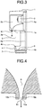
- FIGS. 1 to 3 illustrate the hand dryer shown in the first embodiment of the present invention in which FIG. 1 is a perspective view illustrating the outer appearance of the hand dryer, FIG. 2 is a right-side view of the hand dryer, and FIG. 3 is a right-side cross-sectional view of the hand dryer.
- FIG. 1 is a perspective view illustrating the outer appearance of the hand dryer
- FIG. 2 is a right-side view of the hand dryer
- FIG. 3 is a right-side cross-sectional view of the hand dryer.
- a front-back direction, a left-right direction, and an upper-lower direction described in the first embodiment will be defined.
- the front-back direction the front (user side) of the hand dryer is referred to as "front", and the side opposite from the front is "back".
- the right side when the hand dryer is seen by a user standing in front of the front of the hand dryer, the right side is referred to as "right", and the left side is “left".
- the upper-lower direction the upper side is referred to as “upper”, and the lower side is “lower”.
- a casing 1 forms an upper outer shell of the hand dryer.
- a drying space 3 having a drying space entrance 3a in its front is provided under the casing 1.
- the drying space 3 is a space which is open at the front and the left and right sides so that hands can be freely inserted and withdrawn.
- a water receiving part 4 is constituted by a plane-shaped upper water receiving portion 4a joined to and extending downward from a lower surface 1a of the casing 1, a plane-shaped lower water receiving portion 4b joined to and extending forward from a lower end of the upper water receiving portion 4a, and a plane-shaped protective wall structure 4c extending upward from edges of the upper water receiving portion 4a and the lower water receiving portion 4b.
- the upper water receiving portion 4a, the lower water receiving portion 4b, and the protective wall structure 4c are integrally formed.
- the upper water receiving portion 4a and lower water receiving portion 4b of the water receiving part 4 receive water droplets blown away from hands while being inserted in the drying space, and the protective wall structure 4c plays the role of a dam so as to stop water received by the upper water receiving portion 4a and lower water receiving portion 4b from flowing outside the upper water receiving portion 4a and lower water receiving portion 4b.
- the upper water receiving portion 4a is provided at the back of the drying space 3
- the lower water receiving portion 4b is provided under part of the drying space 3.
- the drying space 3 is an open space partially surrounded by the lower surface 1a of the casing 1 and the water receiving part 4.
- the lower water receiving portion 4b slightly slopes obliquely downward toward the front and has a drain outlet 6 provided at the lowest part thereof.
- a drain container 7 of an open vessel structure to store water having dribbled through the drain outlet 6 is attached under the lower water receiving portion 4b in such a way that it can be withdrawn from and inserted into the lower water receiving portion 4b of the water receiving part 4.
- a nozzle 10 is provided near a front end of the lower surface 1a of the casing 1 so as to protrude downward from the lower surface 1a.
- Air inlets 8 are provided in left and right opposite side surfaces of the casing 1.
- Air ducts 5a and 5b connecting the air inlets 8 and the nozzle 10 are provided inside the casing 1, and a high-pressure airflow generating device 9 to generate a high-pressure airflow is incorporated between the air ducts 5a and 5b.
- the nozzle 10 is open vertically downward.
- the positional relation between the nozzle 10 and the water receiving part 4 will be described.
- the upper water receiving portion 4a, the lower water receiving portion 4b, and the protective wall structure 4c are so positioned as to offset or shifted rearward in the front-back direction from a position on an extension of a blow direction (of a high-speed airflow) from the nozzle 10. That is, an extension line of the blow direction of the nozzle 10 and the water receiving part 4 do not intersect and are in a positional relation where they are offset from each other with the water receiving part 4 not being located at a position on an extension of the blow direction of the nozzle 10.
- the blow direction of the nozzle 10 refers to a direction in which the high-speed airflow is blown out from the nozzle 10 and is the same as a direction of the airflow immediately after blown out from the nozzle 10.
- FIG. 4 is an enlarged side cross-sectional view of the nozzle 10 in FIG. 3 .
- An air jet hole 10a is a narrow passage through which the airflow to be blown out from the nozzle 10 passes and becomes narrower as it goes from an upstream side to a downstream side (exit) of the airflow passing therethrough.
- inner walls 10b and 10c are opposite inner walls of the air jet hole 10a along the front-back direction.
- a straight line passing between the inner walls 10b and 10c and obtained by joining points at equal distances from the inner walls 10b and 10c is called a center axis A.
- the upper water receiving portion 4a, the lower water receiving portion 4b, and the protective wall structure 4c all are positioned with a rearward shift in the front-back direction from a position on an extension of the center axis A of the air jet hole 10a.
- An opening that is an exit opening end of the air jet hole 10a of the nozzle 10 does not directly face the water receiving part 4 and is offset in the front-back direction from the water receiving part 4.
- the opening of the nozzle 10 directly faces the floor of the room, so that the blow direction of the nozzle 10 is oriented toward that floor. That is, when projected along a vertical direction that is the blow direction of the high-speed airflow, the position of the opening of the nozzle 10 does not overlap the position of the water receiving part 4, and the water receiving part 4 is so positioned as to be offset or shifted rearward from the opening of the nozzle 10.
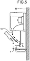
- FIG. 5 is an explanatory view illustrating the state where a user is using the hand dryer of the first embodiment.
- the hand dryer of the first embodiment is installed on a wall 50 of a room such as a toilet.
- a hand detecting sensor (not illustrated) for detecting the presence/non-presence of hands in the drying space 3 detects the hands.
- the hand detecting sensor (not illustrated) detecting hands causes the high-pressure airflow generating device 9 to operate so that external air is sucked into the air duct 5a through the air inlet 8.
- the sucked-in air is converted into a high-pressure airflow by the high-pressure airflow generating device 9.
- the converted high-pressure airflow passes through the air duct 5b and is converted into a high-speed airflow by the nozzle 10 so as to be blown downward along a vertical direction as a high-speed airflow at 60 m/s or greater from the nozzle 10 toward the drying space 3.
- the speed of the high-speed airflow should be set at 100 m/s or greater, more preferably 150 m/s or greater if shortening of the drying time is given higher priority irrespective of an increase in jet noise.
- the hand dryer is installed such that the drying space 3 is located lower than the shoulders of users so that the users easily insert their hands, and thus the hand inserted into the drying space 3 from the front inclines naturally such that the fingertips are lower than the wrist, so that the hand is in a position in which it extends obliquely downward toward the back (in an oblique direction between backward and downward). Then the high-speed airflow blown vertically downward from the nozzle 10 collides at an angle with the hands inserted inclining obliquely downward toward the back. Thus, most of the collided high-speed airflow changes into an airflow advancing along the hands toward the fingertips, that is, an airflow advancing obliquely downward toward the back.
- the nozzle 10 has an elongated slot-shaped opening extending in the left-right direction, so that the high-speed airflow blown out from the nozzle 10 is elongated extending in the left-right direction.
- the high-speed airflow blown out from the nozzle 10 is formed to have an enough transverse width with respect to the width of the inserted hands, so that the high-speed airflow sufficiently hits the inserted hands without being affected by the width and transverse location of the inserted hands. Water sticking to the hands is separated and blown away from the hands by the high-speed airflow blown out from the nozzle 10.
- the user slowly withdraws the hands inserted in the drying space 3, so that the collision position of the high-speed airflow from the nozzle 10 on the surface of the inserted hands gradually moves from the wrist side to the fingertip side, and thus water on the entire hand is blown away.
- a length of the nozzle 10 in the left-right direction should be 80 mm or greater if one hand is to be dried, 150 mm or greater if both hands are to be simultaneously dried, and more preferably 200 mm or greater. If the nozzle 10 is divided into a plurality of parts along the left-right direction, a combined length of the divided parts of the nozzle 10 is taken to be the entire length in the left-right direction of the divided nozzle 10.
- the slot width of the nozzle 10 is preferably 2 mm or less for obtaining a high-speed airflow.
- a high-speed airflow not having been subjected to collision with the inserted hands is allowed to advance vertically downward while keeping its flow direction unchanged and its flow speed less attenuated because of no collision with the hands. Then because the water receiving part 4 is not present in its advancing direction, the high-speed airflow is allowed to pass through the vicinity of the water receiving part 4 without colliding with the water receiving part 4 and flows vertically downward toward the floor.
- the water receiving part 4 that is, the upper water receiving portion 4a, the lower water receiving portion 4b, and the protective wall structure 4c all are so positioned as to be offset or shifted rearward in the front-back direction from a position on an extension of the blow direction (of a high-speed airflow) from the nozzle 10.
- An extension line of the blow direction of the nozzle 10 and the water receiving part 4 do not intersect, and the water receiving part 4 is not located at a position on an extension of the blow direction of the nozzle 10 but located behind.
- the water receiving part 4 is so positioned as to be shifted rearward in the front-back direction from a position on an extension of the center axis A of the air jet hole 10a.
- the opening that is the exit opening end of the air jet hole 10a of the nozzle 10 does not directly face the water receiving part 4 and is offset therefrom in the front-back direction.
- the water receiving part 4 is not located in the advancing direction of a high-speed airflow not having been subjected to a change in direction of flow due to collision with the inserted hands (e.g., a high-speed airflow located transversely outward of the inserted hands), such a part of the high-speed airflow blown out from the nozzle 10, which has not been subjected to collision with the hand, is allowed to passes through the vicinity of the front of the water receiving part 4 with almost not colliding with the water receiving part 4 either.
- the high-speed airflow having collided with the inserted hands has its wind direction changed due to the collision so as to change into an airflow advancing along the hands toward the fingertips to flow obliquely downward toward the back.
- Water droplets separated from the hands by collision with the high-speed airflow are carried by a wind obliquely downward toward the back to be blown away toward the water receiving part 4 and are received by the water receiving part 4.
- the opening of the nozzle 10 and the water receiving part 4 do not directly face each other, and the water receiving part 4 is not located at a position on an extension of the center axis A, and the water receiving part 4 is not located at a position on an extension of the blow direction of the nozzle 10, but, because the water receiving part 4 is placed in the direction in which water droplets are blown away, the water receiving part 4 can effectively receive water droplets blown away from the hands and allow the drain container 7 to collect the water droplets, so that the floor does not become wet to be dirty.
- the hand dryer of the present invention has the water receiving part 4 effectively receive water droplets blown away from the hands and prevents such a high-speed airflow, which has not contributed to drying of the hands due to no collision with the hands, from directly colliding with the water receiving part 4, so that noise produced when the water receiving part 4 and a high-speed airflow collide can be reduced without harming the ability to collect water droplets with the water receiving part 4.
- the water receiving part 4 can have general selectivity that it receives water droplets blown away from the hands and that it hardly directly receives the high-speed airflow blown out from the nozzle 10, and thus both collecting water droplets and a reduction in noise can be achieved by the water receiving part 4.
- the high-pressure airflow generating device 9 is automatically stopped by the hand detecting sensor (not illustrated) to stop blowing the high-speed airflow out from the nozzle 10.
- the hand detecting sensor not illustrated
- the high-speed airflow needs to be stopped, but it is difficult to accurately detect the positions of the fingertips by the hand detecting sensor (not illustrated).
- a delayed operation is provided such that the hand dryer is made to keep blowing out the high-speed airflow for about 0.5 to 2 sec even after the hand detecting sensor (not illustrated) detects that the hands have been pulled out of the drying space 3 and then to stop blowing out the high-speed airflow, and thus blowing out the high-speed airflow is stopped after having the high-speed airflow certainly hit up to the fingertips.
- the present invention provides the above delayed operation, in which the high-speed airflow continues to be blown out from the nozzle 10 while hands are not inserted in the drying space 3, because the high-speed airflow does not directly collide with the water receiving part 4, uncomfortable noise not directly connected with the drying for the user can be reduced.
- FIGS. 6 and 7 are side views illustrating other practical examples of the hand dryer of the first embodiment concerning the blow direction of the high-speed airflow from the nozzle 10.
- FIG. 8 is an enlarged side cross-sectional view of the nozzle 10 in FIG. 6 .
- FIG. 9 is an enlarged side cross-sectional view of the nozzle 10 in FIG. 7 .
- the blow direction of the nozzle 10 is obliquely downward toward the front (in an oblique direction between toward the front and downward) rather than in a vertical direction
- the blow direction of the nozzle 10 is obliquely downward toward the back (in an oblique direction between toward the back and downward) rather than in a vertical direction.
- the hand dryers illustrated in FIGS. 6 , 7 , 8, and 9 have the above effects, and in addition since the blow direction of the nozzle 10 is obliquely downward toward the front (in an oblique direction between toward the front and vertically downward) rather than in a vertical direction in FIGS. 6 and 8 , the size along the front-back direction of the drying space 3 can be greater than the size along the front-back direction of the hand dryer. Thus, with securing an enough size along the front-back direction of the drying space 3 for the inserted hands, the size along the front-back direction of the hand dryer can be decreased. Furthermore, the hand dryer of FIGS. 7 and 9 can reduce wind bouncing back to the user.
- the first embodiment shows an example in which the water receiving part 4 is placed such that its front end is located in front of a position at a distance of 1/2 of L1 so that L2 > 1/2 x L1 is satisfied, where, along the front-back direction, L1 is the distance between the front end and a back or rear end of the lower surface 1a of the casing 1 and L2 is the distance between the front end of the water receiving part 4 and the rear end of the lower surface 1a of the casing 1, if, as illustrated in FIG.
- the water receiving part 4 is placed rearward of the position at a distance of 1/2 of the distance L1 between the front end and the rear end of the lower surface 1a of the casing 1 so that L2 ⁇ 1/2 ⁇ L1 is satisfied, the length over which the water receiving part 4 extends forward will be further shorter. Therefore, when a user inserts the hands into the drying space 3, it is difficult for the user to see the water receiving part 4 due to the presence of the casing 1, so that the user feels that the drying space 3 is large, and thus a feeling of psychological oppression when inserting the hands into the drying space 3 can also be reduced.
- the second embodiment takes the form of a hand dryer mountable to a wall.
- FIG. 10 is a right side view illustrating the state where the hand dryer shown in the second embodiment of the present invention is mounted to a wall 50.
- FIG. 11 is a perspective view illustrating the state where the hand dryer shown in the second embodiment is mounted to the wall 50.
- an air inlet 8, air ducts 5a and 5b, a high-pressure airflow generating device 9, and a nozzle 10 are provided in a casing 1 as in the first embodiment, but the air ducts 5a and 5b and the high-pressure airflow generating device 9 provided inside the casing 1 are omitted from illustration in these figures.
- the casing 1, the air inlet 8, the air ducts 5a and 5b, the high-pressure airflow generating device 9, and the nozzle 10 are combined into a blower unit 100 that is a single unit having a blower function.
- the casing 1 and the water receiving part 4 are independent of each other. That is, the blower unit 100 and the water receiving part 4 are independent of each other.
- the blower unit 100 and the water receiving part 4 are attached independent of each other to the wall 50 to which the hand dryer is to be attached.
- the water receiving part 4 is placed below the blower unit 100.
- the drain container 7 to store water received by the water receiving part 4 is attached under the water receiving part 4 in such a way that it can be withdrawn from and inserted into the water receiving part 4.
- the second embodiment differs from the first embodiment only in that the blower unit 100 and the water receiving part 4 are independent of each other and is the same in configuration as the first embodiment except that.
- the hand dryer having the above configuration has the same effects as in the first embodiment, and the position of the water receiving part 4 can be adjusted in installing correspondingly to the environment where the hand dryer is to be attached and users.
- FIGS. 3 to 10 indicate the directions of airflows (except double arrows indicating sizes L1 and L2 in FIG. 7 ).
- 1 casing 1a lower surface, 3 drying space, 3a drying space entrance, 4 water receiving part, 4a upper water receiving portion, 4b lower water receiving portion, 4c protective wall structure, 5a, 5b air duct, 6 drain outlet, 7 drain container, 8 air inlet, 9 high-pressure airflow generating device, 10 nozzle, 10a air jet hole, lOb, 10c inner wall, 50 wall, 100 blower unit.
Landscapes
- Health & Medical Sciences (AREA)
- Public Health (AREA)
- Domestic Plumbing Installations (AREA)
- Bidet-Like Cleaning Device And Other Flush Toilet Accessories (AREA)
- Detail Structures Of Washing Machines And Dryers (AREA)
Abstract
Description
- The present invention relates to a hand dryer for users to dry their hands wet with water after washing the hands in hand wash, etc., in a powder room, a bathroom, a lavatory, or the like.
- As a conventional hand dryer, for example,
Patent Literature 1 describes a hand dryer which includes a drying space through which hands can be inserted or removed, a nozzle for blowing out high-speed air, and a water receiving part for collecting water droplets blown away by the high-speed airflow from the nozzle. - Further, for example, Patent Literature 2 describes a hand dryer which includes a drying space through which hands can be inserted or removed, a nozzle for blowing out a high-speed airflow, and a water receiving part for collecting water droplets blown away by the high-speed airflow from the nozzle. The position of the nozzle or the water receiving part is changed such that at the time of starting operation, the water receiving part is located in a direction of the high-speed airflow blown out from the nozzle, and as time goes on, the water receiving part is not located in the direction of the high-speed airflow blown out from the nozzle. In this hand dryer, most of water droplets sticking to the hands are blown away during a first drying process that begins at operation start, and moisture on the surfaces of the hands is evaporated during a second drying process. During the first drying process, the water receiving part is at a position on an extension of the direction of the high-speed airflow blown out from the nozzle, and water droplets blown away from the hands are received by the water receiving part. During the second drying process, with almost no water droplets to be blown away from the hand to fly, moisture moistening the surface of the hand is merely evaporated, and thus water need not be received by the water receiving part. Therefore, during the second drying process, the position of the nozzle or water receiving part is changed so that the water receiving part is not located on an extension of the direction of the high-speed airflow from the nozzle so as to preclude direct collision of the high-speed airflow from the nozzle and the water receiving part, thereby greatly reducing noise production.
-
- Patent Literature 1: Japanese Patent Application Laid-open Publication No.
2004-290529 FIGS. 2 and5 ) - Patent Literature 2: Japanese Patent Application Laid-open Publication No.
2004-321485 claim 1, paragraphs [0012] and [0013],FIG. 1 ) - However, in the conventional hand dryer described in
Patent Literature 1, because the water receiving part is in the direction of the high-speed airflow blown out from the nozzle, there is the problem that a part of the airflow not having hit the hand will hit the water receiving part without much attenuation of its wind speed and, hence, noise is produced. - Also in the conventional hand dryer described in Patent Literature 2, because the water receiving part is located on an extension of the direction of the high-speed airflow from the nozzle during the first drying process beginning at operation start in order to receive water droplets blown away from the hand, as in
Patent Literature 1, there is the problem that a part of the airflow not having hit the hand, with its wind speed not much attenuated, will hit the water receiving part and produce noise. - The present invention was made in order to solve the above problems, and an object thereof is to provide a hand dryer which has a water receiving part that receives water droplets separated from the hands by the airflow blown out from the nozzle while reducing direct collision of the airflow blown out from the nozzle and the water receiving part to reduce noise produced by the collision when used.
- In order to solve the above problems, and in order to attain the above object, a hand dryer according to a first aspect of the present invention includes: a nozzle for blowing out an airflow toward a drying space; and a water receiving part that receives water droplets blown away from hands in the drying space by the airflow blown out from the nozzle, wherein while the airflow is being blown out from the nozzle, the water receiving part and the nozzle do not directly face each other.
- A hand dryer according to a second aspect of the present invention includes: a nozzle for blowing out an airflow toward a drying space; and a water receiving part that receives water droplets blown away from hands in the drying space by the airflow blown out from the nozzle, wherein while the airflow is being blown out from the nozzle, the water receiving part is not located on an extension of a blow direction of the nozzle.
- A hand dryer according to a third aspect of the present invention includes: a nozzle for blowing out an airflow toward a drying space; and a water receiving part that receives water droplets blown away from hands in the drying space by the airflow blown out from the nozzle, wherein while the airflow is being blown out from the nozzle, the water receiving part is not located on an extension of a center axis of an air jet hole of the nozzle.
- According to the present invention, there can be provided a hand dryer that realizes a water receiving part to efficiently receive water droplets separated from the hands and to reduce direct collision with the airflow blown out from the nozzle so as to achieve both efficient collection of water droplets and a reduction of noise.
-
-
FIG. 1 is a perspective view of a hand dryer illustrated in a first embodiment of the present invention. -
FIG. 2 is a right-side view of the hand dryer illustrated in the first embodiment of the present invention. -
FIG. 3 is a right-side cross-sectional view of the hand dryer illustrated in the first embodiment of the present invention. -
FIG. 4 is an enlarged cross-sectional view of the nozzle in -
FIG. 3 of the hand dryer illustrated in the first embodiment of the present invention. -
FIG. 5 is an explanatory view illustrating the state where a user is using the hand dryer illustrated in the first embodiment of the present invention. -
FIG. 6 is a right side view illustrating another practical example of the hand dryer illustrated in the first embodiment of the present invention. -
FIG. 7 is a right side view illustrating still another practical example of the hand dryer illustrated in the first embodiment of the present invention. -
FIG. 8 is an enlarged right side cross-sectional view of the nozzle inFIG. 6 of the hand dryer illustrated in the first embodiment of the present invention. -
FIG. 9 is an enlarged right side cross-sectional view of the nozzle inFIG. 7 of the hand dryer illustrated in the first embodiment of the present invention. -
FIG. 10 is a right side view of a hand dryer illustrated in a second embodiment of the present invention. -
FIG. 11 is a perspective view of the hand dryer illustrated in the second embodiment of the present invention. - The first embodiment takes the form of a wall-mountable hand dryer that can be mounted to a wall.
FIGS. 1 to 3 illustrate the hand dryer shown in the first embodiment of the present invention in whichFIG. 1 is a perspective view illustrating the outer appearance of the hand dryer,FIG. 2 is a right-side view of the hand dryer, andFIG. 3 is a right-side cross-sectional view of the hand dryer. First, a front-back direction, a left-right direction, and an upper-lower direction described in the first embodiment will be defined. As to the front-back direction, the front (user side) of the hand dryer is referred to as "front", and the side opposite from the front is "back". As to the left-right direction, when the hand dryer is seen by a user standing in front of the front of the hand dryer, the right side is referred to as "right", and the left side is "left". As to the upper-lower direction, the upper side is referred to as "upper", and the lower side is "lower". - In
FIGS. 1 to 3 , acasing 1 forms an upper outer shell of the hand dryer. Adrying space 3 having adrying space entrance 3a in its front is provided under thecasing 1. Thedrying space 3 is a space which is open at the front and the left and right sides so that hands can be freely inserted and withdrawn. Awater receiving part 4 is constituted by a plane-shaped upperwater receiving portion 4a joined to and extending downward from alower surface 1a of thecasing 1, a plane-shaped lowerwater receiving portion 4b joined to and extending forward from a lower end of the upperwater receiving portion 4a, and a plane-shapedprotective wall structure 4c extending upward from edges of the upperwater receiving portion 4a and the lowerwater receiving portion 4b. The upperwater receiving portion 4a, the lowerwater receiving portion 4b, and theprotective wall structure 4c are integrally formed. When used, the upperwater receiving portion 4a and lowerwater receiving portion 4b of thewater receiving part 4 receive water droplets blown away from hands while being inserted in the drying space, and theprotective wall structure 4c plays the role of a dam so as to stop water received by the upperwater receiving portion 4a and lowerwater receiving portion 4b from flowing outside the upperwater receiving portion 4a and lowerwater receiving portion 4b. In the positional relation between thedrying space 3 and thewater receiving part 4, the upperwater receiving portion 4a is provided at the back of thedrying space 3, and the lowerwater receiving portion 4b is provided under part of thedrying space 3. Thus, thedrying space 3 is an open space partially surrounded by thelower surface 1a of thecasing 1 and thewater receiving part 4. - The lower
water receiving portion 4b slightly slopes obliquely downward toward the front and has adrain outlet 6 provided at the lowest part thereof. Adrain container 7 of an open vessel structure to store water having dribbled through thedrain outlet 6 is attached under the lowerwater receiving portion 4b in such a way that it can be withdrawn from and inserted into the lowerwater receiving portion 4b of thewater receiving part 4. - A
nozzle 10 is provided near a front end of thelower surface 1a of thecasing 1 so as to protrude downward from thelower surface 1a.Air inlets 8 are provided in left and right opposite side surfaces of thecasing 1.Air ducts air inlets 8 and thenozzle 10 are provided inside thecasing 1, and a high-pressure airflow generatingdevice 9 to generate a high-pressure airflow is incorporated between theair ducts - The
nozzle 10 is open vertically downward. The positional relation between thenozzle 10 and thewater receiving part 4 will be described. The upperwater receiving portion 4a, the lowerwater receiving portion 4b, and theprotective wall structure 4c are so positioned as to offset or shifted rearward in the front-back direction from a position on an extension of a blow direction (of a high-speed airflow) from thenozzle 10. That is, an extension line of the blow direction of thenozzle 10 and thewater receiving part 4 do not intersect and are in a positional relation where they are offset from each other with thewater receiving part 4 not being located at a position on an extension of the blow direction of thenozzle 10. Here, the blow direction of thenozzle 10 refers to a direction in which the high-speed airflow is blown out from thenozzle 10 and is the same as a direction of the airflow immediately after blown out from thenozzle 10. -
FIG. 4 is an enlarged side cross-sectional view of thenozzle 10 inFIG. 3 . Anair jet hole 10a is a narrow passage through which the airflow to be blown out from thenozzle 10 passes and becomes narrower as it goes from an upstream side to a downstream side (exit) of the airflow passing therethrough. In a side cross-section taken along a plane extending in the front-back direction and vertically through theair jet hole 10a of thenozzle 10,inner walls air jet hole 10a along the front-back direction. As illustrated inFIG. 4 , a straight line passing between theinner walls inner walls water receiving portion 4a, the lowerwater receiving portion 4b, and theprotective wall structure 4c all are positioned with a rearward shift in the front-back direction from a position on an extension of the center axis A of theair jet hole 10a. - An opening that is an exit opening end of the
air jet hole 10a of thenozzle 10 does not directly face thewater receiving part 4 and is offset in the front-back direction from thewater receiving part 4. Thus, when the hand dryer is mounted to a wall of a room such as a toilet, the opening of thenozzle 10 directly faces the floor of the room, so that the blow direction of thenozzle 10 is oriented toward that floor. That is, when projected along a vertical direction that is the blow direction of the high-speed airflow, the position of the opening of thenozzle 10 does not overlap the position of thewater receiving part 4, and thewater receiving part 4 is so positioned as to be offset or shifted rearward from the opening of thenozzle 10. - Next, the flow of air and the flow of water droplets while the hand dryer is operating will be described.
FIG. 5 is an explanatory view illustrating the state where a user is using the hand dryer of the first embodiment. As illustrated inFIG. 5 , the hand dryer of the first embodiment is installed on awall 50 of a room such as a toilet. When a user stands in front of the front of the hand dryer and inserts wet hands into the dryingspace 3 through the dryingspace entrance 3a, a hand detecting sensor (not illustrated) for detecting the presence/non-presence of hands in the dryingspace 3 detects the hands. Then the hand detecting sensor (not illustrated) detecting hands causes the high-pressureairflow generating device 9 to operate so that external air is sucked into theair duct 5a through theair inlet 8. The sucked-in air is converted into a high-pressure airflow by the high-pressureairflow generating device 9. Then the converted high-pressure airflow passes through theair duct 5b and is converted into a high-speed airflow by thenozzle 10 so as to be blown downward along a vertical direction as a high-speed airflow at 60 m/s or greater from thenozzle 10 toward the dryingspace 3. Although, as the speed of the high-speed airflow increases, jet noise produced from thenozzle 10 also increases, the speed of the high-speed airflow should be set at 100 m/s or greater, more preferably 150 m/s or greater if shortening of the drying time is given higher priority irrespective of an increase in jet noise. - The hand dryer is installed such that the drying
space 3 is located lower than the shoulders of users so that the users easily insert their hands, and thus the hand inserted into the dryingspace 3 from the front inclines naturally such that the fingertips are lower than the wrist, so that the hand is in a position in which it extends obliquely downward toward the back (in an oblique direction between backward and downward). Then the high-speed airflow blown vertically downward from thenozzle 10 collides at an angle with the hands inserted inclining obliquely downward toward the back. Thus, most of the collided high-speed airflow changes into an airflow advancing along the hands toward the fingertips, that is, an airflow advancing obliquely downward toward the back. In the direction referred to by the "obliquely downward toward the back", there is thewater receiving part 4, so that the airflow advancing obliquely downward toward the back, flows toward thewater receiving part 4. Water sticking to the hands is blown away by the airflow colliding with the hands to be blown away toward thewater receiving part 4 by the airflow advancing obliquely downward toward the back. Water droplets blown away toward thewater receiving part 4 are received by thewater receiving part 4 and dribble down a surface of thewater receiving part 4 by their own weight and pass through thedrain outlet 6 to be stored in thedrain container 7. - The
nozzle 10 has an elongated slot-shaped opening extending in the left-right direction, so that the high-speed airflow blown out from thenozzle 10 is elongated extending in the left-right direction. The high-speed airflow blown out from thenozzle 10 is formed to have an enough transverse width with respect to the width of the inserted hands, so that the high-speed airflow sufficiently hits the inserted hands without being affected by the width and transverse location of the inserted hands. Water sticking to the hands is separated and blown away from the hands by the high-speed airflow blown out from thenozzle 10. Then while the high-speed airflow is being blown out from thenozzle 10, the user slowly withdraws the hands inserted in the dryingspace 3, so that the collision position of the high-speed airflow from thenozzle 10 on the surface of the inserted hands gradually moves from the wrist side to the fingertip side, and thus water on the entire hand is blown away. - A length of the
nozzle 10 in the left-right direction should be 80 mm or greater if one hand is to be dried, 150 mm or greater if both hands are to be simultaneously dried, and more preferably 200 mm or greater. If thenozzle 10 is divided into a plurality of parts along the left-right direction, a combined length of the divided parts of thenozzle 10 is taken to be the entire length in the left-right direction of the dividednozzle 10. The slot width of thenozzle 10 is preferably 2 mm or less for obtaining a high-speed airflow. - Out of the high-speed airflow blown out from the
nozzle 10, a high-speed airflow not having been subjected to collision with the inserted hands is allowed to advance vertically downward while keeping its flow direction unchanged and its flow speed less attenuated because of no collision with the hands. Then because thewater receiving part 4 is not present in its advancing direction, the high-speed airflow is allowed to pass through the vicinity of thewater receiving part 4 without colliding with thewater receiving part 4 and flows vertically downward toward the floor. - In the hand dryer having the above configuration, the
water receiving part 4, that is, the upperwater receiving portion 4a, the lowerwater receiving portion 4b, and theprotective wall structure 4c all are so positioned as to be offset or shifted rearward in the front-back direction from a position on an extension of the blow direction (of a high-speed airflow) from thenozzle 10. An extension line of the blow direction of thenozzle 10 and thewater receiving part 4 do not intersect, and thewater receiving part 4 is not located at a position on an extension of the blow direction of thenozzle 10 but located behind. Thewater receiving part 4 is so positioned as to be shifted rearward in the front-back direction from a position on an extension of the center axis A of theair jet hole 10a. The opening that is the exit opening end of theair jet hole 10a of thenozzle 10 does not directly face thewater receiving part 4 and is offset therefrom in the front-back direction. - Because the
water receiving part 4 is not located in the advancing direction of a high-speed airflow not having been subjected to a change in direction of flow due to collision with the inserted hands (e.g., a high-speed airflow located transversely outward of the inserted hands), such a part of the high-speed airflow blown out from thenozzle 10, which has not been subjected to collision with the hand, is allowed to passes through the vicinity of the front of thewater receiving part 4 with almost not colliding with thewater receiving part 4 either. As such, because such a part of the high-speed airflow blown out from the nozzle and not subjected with collision with the hands does not undergo direct collision with thewater receiving part 4, noise produced by collision of a high-speed airflow and thewater receiving part 4 can be suppressed, so that noise during the use of the hand dryer can be reduced. Especially the high-speed airflow not subjected to a change in direction of flow due to collision with the hands maintains a high speed without wind-speed attenuation due to collision, and thus, collision with thewater receiving part 4 would produce conspicuous noise, but noise can be effectively reduced by avoiding direct collision with thewater receiving part 4. - In contrast, out of the high-speed airflow blown out vertically downward from the
nozzle 10, the high-speed airflow having collided with the inserted hands has its wind direction changed due to the collision so as to change into an airflow advancing along the hands toward the fingertips to flow obliquely downward toward the back. Water droplets separated from the hands by collision with the high-speed airflow are carried by a wind obliquely downward toward the back to be blown away toward thewater receiving part 4 and are received by thewater receiving part 4. As such, the opening of thenozzle 10 and thewater receiving part 4 do not directly face each other, and thewater receiving part 4 is not located at a position on an extension of the center axis A, and thewater receiving part 4 is not located at a position on an extension of the blow direction of thenozzle 10, but, because thewater receiving part 4 is placed in the direction in which water droplets are blown away, thewater receiving part 4 can effectively receive water droplets blown away from the hands and allow thedrain container 7 to collect the water droplets, so that the floor does not become wet to be dirty. - Therefore, the hand dryer of the present invention has the
water receiving part 4 effectively receive water droplets blown away from the hands and prevents such a high-speed airflow, which has not contributed to drying of the hands due to no collision with the hands, from directly colliding with thewater receiving part 4, so that noise produced when thewater receiving part 4 and a high-speed airflow collide can be reduced without harming the ability to collect water droplets with thewater receiving part 4. In other words, thewater receiving part 4 can have general selectivity that it receives water droplets blown away from the hands and that it hardly directly receives the high-speed airflow blown out from thenozzle 10, and thus both collecting water droplets and a reduction in noise can be achieved by thewater receiving part 4. - In the hand dryer, when the hands are pulled out of the drying
space 3, the high-pressureairflow generating device 9 is automatically stopped by the hand detecting sensor (not illustrated) to stop blowing the high-speed airflow out from thenozzle 10. In order to certainly dry up to the fingertips, after having the high-speed airflow certainly hit up to the fingertips of the inserted hands, the high-speed airflow needs to be stopped, but it is difficult to accurately detect the positions of the fingertips by the hand detecting sensor (not illustrated). Accordingly, in general, a delayed operation is provided such that the hand dryer is made to keep blowing out the high-speed airflow for about 0.5 to 2 sec even after the hand detecting sensor (not illustrated) detects that the hands have been pulled out of the dryingspace 3 and then to stop blowing out the high-speed airflow, and thus blowing out the high-speed airflow is stopped after having the high-speed airflow certainly hit up to the fingertips. - In this delayed operation, after the hands are pulled out of the drying
space 3, the high-speed airflow continues blowing out from thenozzle 10 while hands are not inserted in the dryingspace 3, so that noise associated with the operation of the hand dryer continues for a while even after a user finishes drying. For users, noise in drying associated with the operation for themselves is likely to be tolerable, but, because of not being directly connected with the drying of the user, noise after finishing drying is difficult to tolerate even if the noise occurs for a short time of about 0.5 to 2 sec, so that the user feels very uncomfortable. - However, although the present invention provides the above delayed operation, in which the high-speed airflow continues to be blown out from the
nozzle 10 while hands are not inserted in the dryingspace 3, because the high-speed airflow does not directly collide with thewater receiving part 4, uncomfortable noise not directly connected with the drying for the user can be reduced. - Although the first embodiment describes that the blow direction of the high-speed airflow from the
nozzle 10 is vertically downward, the blow direction of the high-speed airflow from thenozzle 10, not being limited to this, may be at an angle whether forward, backward, leftward, or rightward as long as being downward. For example,FIGS. 6 and7 are side views illustrating other practical examples of the hand dryer of the first embodiment concerning the blow direction of the high-speed airflow from thenozzle 10.FIG. 8 is an enlarged side cross-sectional view of thenozzle 10 inFIG. 6 .FIG. 9 is an enlarged side cross-sectional view of thenozzle 10 inFIG. 7 . InFIGS. 6 and8 , the blow direction of thenozzle 10 is obliquely downward toward the front (in an oblique direction between toward the front and downward) rather than in a vertical direction, and inFIGS. 7 and9 , the blow direction of thenozzle 10 is obliquely downward toward the back (in an oblique direction between toward the back and downward) rather than in a vertical direction. - The hand dryers illustrated in
FIGS. 6 ,7 ,8, and 9 have the above effects, and in addition since the blow direction of thenozzle 10 is obliquely downward toward the front (in an oblique direction between toward the front and vertically downward) rather than in a vertical direction inFIGS. 6 and8 , the size along the front-back direction of the dryingspace 3 can be greater than the size along the front-back direction of the hand dryer. Thus, with securing an enough size along the front-back direction of the dryingspace 3 for the inserted hands, the size along the front-back direction of the hand dryer can be decreased. Furthermore, the hand dryer ofFIGS. 7 and9 can reduce wind bouncing back to the user. - Although the first embodiment shows an example in which the
water receiving part 4 is placed such that its front end is located in front of a position at a distance of 1/2 of L1 so that L2 > 1/2 x L1 is satisfied, where, along the front-back direction, L1 is the distance between the front end and a back or rear end of thelower surface 1a of thecasing 1 and L2 is the distance between the front end of thewater receiving part 4 and the rear end of thelower surface 1a of thecasing 1, if, as illustrated inFIG. 9 , with the blow direction of thenozzle 10 being made obliquely backward, thewater receiving part 4 is placed rearward of the position at a distance of 1/2 of the distance L1 between the front end and the rear end of thelower surface 1a of thecasing 1 so that L2 ≤ 1/2 × L1 is satisfied, the length over which thewater receiving part 4 extends forward will be further shorter. Therefore, when a user inserts the hands into the dryingspace 3, it is difficult for the user to see thewater receiving part 4 due to the presence of thecasing 1, so that the user feels that the dryingspace 3 is large, and thus a feeling of psychological oppression when inserting the hands into the dryingspace 3 can also be reduced. - The second embodiment takes the form of a hand dryer mountable to a wall.
FIG. 10 is a right side view illustrating the state where the hand dryer shown in the second embodiment of the present invention is mounted to awall 50.FIG. 11 is a perspective view illustrating the state where the hand dryer shown in the second embodiment is mounted to thewall 50. InFIGS. 10 and11 , anair inlet 8,air ducts airflow generating device 9, and anozzle 10 are provided in acasing 1 as in the first embodiment, but theair ducts airflow generating device 9 provided inside thecasing 1 are omitted from illustration in these figures. Thecasing 1, theair inlet 8, theair ducts airflow generating device 9, and thenozzle 10 are combined into ablower unit 100 that is a single unit having a blower function. In the second embodiment, thecasing 1 and thewater receiving part 4 are independent of each other. That is, theblower unit 100 and thewater receiving part 4 are independent of each other. Thus, theblower unit 100 and thewater receiving part 4 are attached independent of each other to thewall 50 to which the hand dryer is to be attached. Thewater receiving part 4 is placed below theblower unit 100. Thedrain container 7 to store water received by thewater receiving part 4 is attached under thewater receiving part 4 in such a way that it can be withdrawn from and inserted into thewater receiving part 4. The second embodiment differs from the first embodiment only in that theblower unit 100 and thewater receiving part 4 are independent of each other and is the same in configuration as the first embodiment except that. - The hand dryer having the above configuration has the same effects as in the first embodiment, and the position of the
water receiving part 4 can be adjusted in installing correspondingly to the environment where the hand dryer is to be attached and users. - Note that the arrows shown in
FIGS. 3 to 10 indicate the directions of airflows (except double arrows indicating sizes L1 and L2 inFIG. 7 ). - 1 casing, 1a lower surface, 3 drying space, 3a drying space entrance, 4 water receiving part, 4a upper water receiving portion, 4b lower water receiving portion, 4c protective wall structure, 5a, 5b air duct, 6 drain outlet, 7 drain container, 8 air inlet, 9 high-pressure airflow generating device, 10 nozzle, 10a air jet hole, lOb, 10c inner wall, 50 wall, 100 blower unit.
Claims (7)
- A hand dryer comprising:a nozzle for blowing out an airflow toward a drying space; anda water receiving part that receives water droplets blown away from hands in the drying space by the airflow blown out from the nozzle,wherein while the airflow is being blown out from the nozzle, the water receiving part and the nozzle do not directly face each other.
- A hand dryer comprising:a nozzle for blowing out an airflow toward a drying space; anda water receiving part that receives water droplets blown away from hands in the drying space by the airflow blown out from the nozzle,wherein while the airflow is being blown out from the nozzle, the water receiving part is not located on an extension of a blow direction of the nozzle.
- A hand dryer comprising:a nozzle for blowing out an airflow toward a drying space; anda water receiving part that receives water droplets blown away from hands in the drying space by the airflow blown out from the nozzle,wherein while the airflow is being blown out from the nozzle, the water receiving part is not located on an extension of a center axis of an air jet hole of the nozzle.
- The hand dryer according to claim 1, wherein the drying space is open at least at the front, and the water receiving part is located rearward of the nozzle.
- The hand dryer according to claim 2, wherein the drying space is open at least at the front, and the water receiving part is located rearward of the extension of the blow direction of the nozzle.
- The hand dryer according to claim 3, wherein the drying space is open at least at the front, and the water receiving part is located rearward of the extension of the center axis of the air jet hole.
- The hand dryer according to any one of claims 1 to 6, wherein the nozzle is provided in a casing forming an outer shell, and the water receiving part is placed rearward of a position at a distance of half of a distance between a front end and a rear end of the casing along a front-back direction.
Applications Claiming Priority (2)
| Application Number | Priority Date | Filing Date | Title |
|---|---|---|---|
| JP2015078245 | 2015-04-07 | ||
| PCT/JP2015/074875 WO2016163041A1 (en) | 2015-04-07 | 2015-09-01 | Hand dryer |
Publications (3)
| Publication Number | Publication Date |
|---|---|
| EP3281573A1 true EP3281573A1 (en) | 2018-02-14 |
| EP3281573A4 EP3281573A4 (en) | 2018-10-17 |
| EP3281573B1 EP3281573B1 (en) | 2021-05-12 |
Family
ID=57072414
Family Applications (1)
| Application Number | Title | Priority Date | Filing Date |
|---|---|---|---|
| EP15888532.7A Active EP3281573B1 (en) | 2015-04-07 | 2015-09-01 | Hand dryer |
Country Status (4)
| Country | Link |
|---|---|
| US (1) | US20180235414A1 (en) |
| EP (1) | EP3281573B1 (en) |
| JP (1) | JP6501871B2 (en) |
| WO (1) | WO2016163041A1 (en) |
Families Citing this family (4)
| Publication number | Priority date | Publication date | Assignee | Title |
|---|---|---|---|---|
| JPWO2018220715A1 (en) * | 2017-05-30 | 2019-08-08 | 三菱電機株式会社 | Hand dryer |
| WO2019035201A1 (en) * | 2017-08-17 | 2019-02-21 | 三菱電機株式会社 | Hand dryer |
| CN112153927B (en) * | 2018-06-01 | 2022-09-27 | 维克洛克控股有限责任公司 | Hand dryer |
| USD1002949S1 (en) * | 2022-03-14 | 2023-10-24 | Guangdong Roman Technology Co., Ltd. | Hand dryer |
Family Cites Families (12)
| Publication number | Priority date | Publication date | Assignee | Title |
|---|---|---|---|---|
| JP3341535B2 (en) * | 1995-07-10 | 2002-11-05 | 三菱電機株式会社 | Hand drying equipment |
| JPH10290767A (en) * | 1997-04-17 | 1998-11-04 | Funai Electric Co Ltd | Hand dryer |
| JP2003260008A (en) * | 2002-03-08 | 2003-09-16 | Hitachi Taga Technol Co Ltd | Hand-drying equipment |
| JP3731126B2 (en) * | 2003-03-24 | 2006-01-05 | 三菱電機株式会社 | Hand dryer |
| JP2004321485A (en) * | 2003-04-24 | 2004-11-18 | Mitsubishi Electric Corp | Hand drying equipment |
| JP4040055B2 (en) * | 2005-08-11 | 2008-01-30 | 三菱電機株式会社 | Hand dryer |
| JP5194497B2 (en) * | 2007-03-14 | 2013-05-08 | パナソニック株式会社 | Hand dryer |
| JP4474483B1 (en) * | 2009-02-06 | 2010-06-02 | シャープ株式会社 | Hand dryer |
| KR101445471B1 (en) * | 2010-07-06 | 2014-09-26 | 미쓰비시덴키 가부시키가이샤 | Hand drying device |
| US8813383B2 (en) * | 2012-03-06 | 2014-08-26 | Hokwang Industries Co., Ltd. | Watermark-free hand dryer |
| JP2014064806A (en) * | 2012-09-26 | 2014-04-17 | Toto Ltd | Hand dryer |
| JP6283824B2 (en) * | 2013-03-26 | 2018-02-28 | パナソニックIpマネジメント株式会社 | Hand dryer |
-
2015
- 2015-09-01 JP JP2017511448A patent/JP6501871B2/en active Active
- 2015-09-01 EP EP15888532.7A patent/EP3281573B1/en active Active
- 2015-09-01 US US15/552,356 patent/US20180235414A1/en not_active Abandoned
- 2015-09-01 WO PCT/JP2015/074875 patent/WO2016163041A1/en not_active Ceased
Also Published As
| Publication number | Publication date |
|---|---|
| EP3281573B1 (en) | 2021-05-12 |
| US20180235414A1 (en) | 2018-08-23 |
| JPWO2016163041A1 (en) | 2017-06-29 |
| JP6501871B2 (en) | 2019-04-17 |
| WO2016163041A1 (en) | 2016-10-13 |
| EP3281573A4 (en) | 2018-10-17 |
Similar Documents
| Publication | Publication Date | Title |
|---|---|---|
| EP3662801B1 (en) | Hand dryer | |
| EP3281573A1 (en) | Hand dryer | |
| JP4184421B2 (en) | Hand dryer | |
| TWI457103B (en) | Hand dryer | |
| JP5138089B2 (en) | Hand dryer | |
| US8201344B2 (en) | Hand drying apparatus | |
| CA2615288C (en) | Drying apparatus | |
| US7614160B2 (en) | Hand drying apparatus | |
| GB2497871A (en) | Hand dryer device | |
| JP5780032B2 (en) | Hand dryer | |
| WO2007015041A1 (en) | Drying apparatus | |
| EP4252604A1 (en) | Hand drying device | |
| JP6657577B2 (en) | Hand drying equipment | |
| JP6385590B2 (en) | Hand dryer | |
| JP6270985B2 (en) | Drying equipment | |
| TH6691A3 (en) | The structure of the air flow channel | |
| TH6691C3 (en) | The structure of the air flow channel |
Legal Events
| Date | Code | Title | Description |
|---|---|---|---|
| STAA | Information on the status of an ep patent application or granted ep patent |
Free format text: STATUS: THE INTERNATIONAL PUBLICATION HAS BEEN MADE |
|
| PUAI | Public reference made under article 153(3) epc to a published international application that has entered the european phase |
Free format text: ORIGINAL CODE: 0009012 |
|
| STAA | Information on the status of an ep patent application or granted ep patent |
Free format text: STATUS: REQUEST FOR EXAMINATION WAS MADE |
|
| 17P | Request for examination filed |
Effective date: 20171013 |
|
| AK | Designated contracting states |
Kind code of ref document: A1 Designated state(s): AL AT BE BG CH CY CZ DE DK EE ES FI FR GB GR HR HU IE IS IT LI LT LU LV MC MK MT NL NO PL PT RO RS SE SI SK SM TR |
|
| AX | Request for extension of the european patent |
Extension state: BA ME |
|
| DAV | Request for validation of the european patent (deleted) | ||
| DAX | Request for extension of the european patent (deleted) | ||
| A4 | Supplementary search report drawn up and despatched |
Effective date: 20180914 |
|
| RIC1 | Information provided on ipc code assigned before grant |
Ipc: A47K 10/48 20060101AFI20180911BHEP |
|
| STAA | Information on the status of an ep patent application or granted ep patent |
Free format text: STATUS: EXAMINATION IS IN PROGRESS |
|
| 17Q | First examination report despatched |
Effective date: 20200327 |
|
| GRAP | Despatch of communication of intention to grant a patent |
Free format text: ORIGINAL CODE: EPIDOSNIGR1 |
|
| STAA | Information on the status of an ep patent application or granted ep patent |
Free format text: STATUS: GRANT OF PATENT IS INTENDED |
|
| INTG | Intention to grant announced |
Effective date: 20201123 |
|
| GRAS | Grant fee paid |
Free format text: ORIGINAL CODE: EPIDOSNIGR3 |
|
| GRAA | (expected) grant |
Free format text: ORIGINAL CODE: 0009210 |
|
| STAA | Information on the status of an ep patent application or granted ep patent |
Free format text: STATUS: THE PATENT HAS BEEN GRANTED |
|
| AK | Designated contracting states |
Kind code of ref document: B1 Designated state(s): AL AT BE BG CH CY CZ DE DK EE ES FI FR GB GR HR HU IE IS IT LI LT LU LV MC MK MT NL NO PL PT RO RS SE SI SK SM TR |
|
| REG | Reference to a national code |
Ref country code: GB Ref legal event code: FG4D |
|
| REG | Reference to a national code |
Ref country code: CH Ref legal event code: EP |
|
| REG | Reference to a national code |
Ref country code: DE Ref legal event code: R096 Ref document number: 602015069333 Country of ref document: DE |
|
| REG | Reference to a national code |
Ref country code: IE Ref legal event code: FG4D |
|
| REG | Reference to a national code |
Ref country code: AT Ref legal event code: REF Ref document number: 1391602 Country of ref document: AT Kind code of ref document: T Effective date: 20210615 |
|
| REG | Reference to a national code |
Ref country code: LT Ref legal event code: MG9D |
|
| REG | Reference to a national code |
Ref country code: AT Ref legal event code: MK05 Ref document number: 1391602 Country of ref document: AT Kind code of ref document: T Effective date: 20210512 |
|
| REG | Reference to a national code |
Ref country code: NL Ref legal event code: MP Effective date: 20210512 |
|
| PG25 | Lapsed in a contracting state [announced via postgrant information from national office to epo] |
Ref country code: LT Free format text: LAPSE BECAUSE OF FAILURE TO SUBMIT A TRANSLATION OF THE DESCRIPTION OR TO PAY THE FEE WITHIN THE PRESCRIBED TIME-LIMIT Effective date: 20210512 Ref country code: FI Free format text: LAPSE BECAUSE OF FAILURE TO SUBMIT A TRANSLATION OF THE DESCRIPTION OR TO PAY THE FEE WITHIN THE PRESCRIBED TIME-LIMIT Effective date: 20210512 Ref country code: HR Free format text: LAPSE BECAUSE OF FAILURE TO SUBMIT A TRANSLATION OF THE DESCRIPTION OR TO PAY THE FEE WITHIN THE PRESCRIBED TIME-LIMIT Effective date: 20210512 Ref country code: AT Free format text: LAPSE BECAUSE OF FAILURE TO SUBMIT A TRANSLATION OF THE DESCRIPTION OR TO PAY THE FEE WITHIN THE PRESCRIBED TIME-LIMIT Effective date: 20210512 Ref country code: BG Free format text: LAPSE BECAUSE OF FAILURE TO SUBMIT A TRANSLATION OF THE DESCRIPTION OR TO PAY THE FEE WITHIN THE PRESCRIBED TIME-LIMIT Effective date: 20210812 |
|
| PG25 | Lapsed in a contracting state [announced via postgrant information from national office to epo] |
Ref country code: IS Free format text: LAPSE BECAUSE OF FAILURE TO SUBMIT A TRANSLATION OF THE DESCRIPTION OR TO PAY THE FEE WITHIN THE PRESCRIBED TIME-LIMIT Effective date: 20210912 Ref country code: LV Free format text: LAPSE BECAUSE OF FAILURE TO SUBMIT A TRANSLATION OF THE DESCRIPTION OR TO PAY THE FEE WITHIN THE PRESCRIBED TIME-LIMIT Effective date: 20210512 Ref country code: GR Free format text: LAPSE BECAUSE OF FAILURE TO SUBMIT A TRANSLATION OF THE DESCRIPTION OR TO PAY THE FEE WITHIN THE PRESCRIBED TIME-LIMIT Effective date: 20210813 Ref country code: PT Free format text: LAPSE BECAUSE OF FAILURE TO SUBMIT A TRANSLATION OF THE DESCRIPTION OR TO PAY THE FEE WITHIN THE PRESCRIBED TIME-LIMIT Effective date: 20210913 Ref country code: PL Free format text: LAPSE BECAUSE OF FAILURE TO SUBMIT A TRANSLATION OF THE DESCRIPTION OR TO PAY THE FEE WITHIN THE PRESCRIBED TIME-LIMIT Effective date: 20210512 Ref country code: NO Free format text: LAPSE BECAUSE OF FAILURE TO SUBMIT A TRANSLATION OF THE DESCRIPTION OR TO PAY THE FEE WITHIN THE PRESCRIBED TIME-LIMIT Effective date: 20210812 Ref country code: SE Free format text: LAPSE BECAUSE OF FAILURE TO SUBMIT A TRANSLATION OF THE DESCRIPTION OR TO PAY THE FEE WITHIN THE PRESCRIBED TIME-LIMIT Effective date: 20210512 Ref country code: RS Free format text: LAPSE BECAUSE OF FAILURE TO SUBMIT A TRANSLATION OF THE DESCRIPTION OR TO PAY THE FEE WITHIN THE PRESCRIBED TIME-LIMIT Effective date: 20210512 |
|
| PG25 | Lapsed in a contracting state [announced via postgrant information from national office to epo] |
Ref country code: NL Free format text: LAPSE BECAUSE OF FAILURE TO SUBMIT A TRANSLATION OF THE DESCRIPTION OR TO PAY THE FEE WITHIN THE PRESCRIBED TIME-LIMIT Effective date: 20210512 |
|
| PG25 | Lapsed in a contracting state [announced via postgrant information from national office to epo] |
Ref country code: SK Free format text: LAPSE BECAUSE OF FAILURE TO SUBMIT A TRANSLATION OF THE DESCRIPTION OR TO PAY THE FEE WITHIN THE PRESCRIBED TIME-LIMIT Effective date: 20210512 Ref country code: SM Free format text: LAPSE BECAUSE OF FAILURE TO SUBMIT A TRANSLATION OF THE DESCRIPTION OR TO PAY THE FEE WITHIN THE PRESCRIBED TIME-LIMIT Effective date: 20210512 Ref country code: CZ Free format text: LAPSE BECAUSE OF FAILURE TO SUBMIT A TRANSLATION OF THE DESCRIPTION OR TO PAY THE FEE WITHIN THE PRESCRIBED TIME-LIMIT Effective date: 20210512 Ref country code: DK Free format text: LAPSE BECAUSE OF FAILURE TO SUBMIT A TRANSLATION OF THE DESCRIPTION OR TO PAY THE FEE WITHIN THE PRESCRIBED TIME-LIMIT Effective date: 20210512 Ref country code: EE Free format text: LAPSE BECAUSE OF FAILURE TO SUBMIT A TRANSLATION OF THE DESCRIPTION OR TO PAY THE FEE WITHIN THE PRESCRIBED TIME-LIMIT Effective date: 20210512 Ref country code: RO Free format text: LAPSE BECAUSE OF FAILURE TO SUBMIT A TRANSLATION OF THE DESCRIPTION OR TO PAY THE FEE WITHIN THE PRESCRIBED TIME-LIMIT Effective date: 20210512 Ref country code: ES Free format text: LAPSE BECAUSE OF FAILURE TO SUBMIT A TRANSLATION OF THE DESCRIPTION OR TO PAY THE FEE WITHIN THE PRESCRIBED TIME-LIMIT Effective date: 20210512 |
|
| REG | Reference to a national code |
Ref country code: DE Ref legal event code: R097 Ref document number: 602015069333 Country of ref document: DE |
|
| PLBE | No opposition filed within time limit |
Free format text: ORIGINAL CODE: 0009261 |
|
| STAA | Information on the status of an ep patent application or granted ep patent |
Free format text: STATUS: NO OPPOSITION FILED WITHIN TIME LIMIT |
|
| 26N | No opposition filed |
Effective date: 20220215 |
|
| REG | Reference to a national code |
Ref country code: CH Ref legal event code: PL |
|
| REG | Reference to a national code |
Ref country code: BE Ref legal event code: MM Effective date: 20210930 |
|
| PG25 | Lapsed in a contracting state [announced via postgrant information from national office to epo] |
Ref country code: IS Free format text: LAPSE BECAUSE OF FAILURE TO SUBMIT A TRANSLATION OF THE DESCRIPTION OR TO PAY THE FEE WITHIN THE PRESCRIBED TIME-LIMIT Effective date: 20210912 Ref country code: MC Free format text: LAPSE BECAUSE OF FAILURE TO SUBMIT A TRANSLATION OF THE DESCRIPTION OR TO PAY THE FEE WITHIN THE PRESCRIBED TIME-LIMIT Effective date: 20210512 Ref country code: AL Free format text: LAPSE BECAUSE OF FAILURE TO SUBMIT A TRANSLATION OF THE DESCRIPTION OR TO PAY THE FEE WITHIN THE PRESCRIBED TIME-LIMIT Effective date: 20210512 |
|
| PG25 | Lapsed in a contracting state [announced via postgrant information from national office to epo] |
Ref country code: LU Free format text: LAPSE BECAUSE OF NON-PAYMENT OF DUE FEES Effective date: 20210901 Ref country code: IT Free format text: LAPSE BECAUSE OF FAILURE TO SUBMIT A TRANSLATION OF THE DESCRIPTION OR TO PAY THE FEE WITHIN THE PRESCRIBED TIME-LIMIT Effective date: 20210512 Ref country code: IE Free format text: LAPSE BECAUSE OF NON-PAYMENT OF DUE FEES Effective date: 20210901 Ref country code: FR Free format text: LAPSE BECAUSE OF NON-PAYMENT OF DUE FEES Effective date: 20210930 Ref country code: BE Free format text: LAPSE BECAUSE OF NON-PAYMENT OF DUE FEES Effective date: 20210930 |
|
| PG25 | Lapsed in a contracting state [announced via postgrant information from national office to epo] |
Ref country code: LI Free format text: LAPSE BECAUSE OF NON-PAYMENT OF DUE FEES Effective date: 20210930 Ref country code: CH Free format text: LAPSE BECAUSE OF NON-PAYMENT OF DUE FEES Effective date: 20210930 |
|
| PG25 | Lapsed in a contracting state [announced via postgrant information from national office to epo] |
Ref country code: HU Free format text: LAPSE BECAUSE OF FAILURE TO SUBMIT A TRANSLATION OF THE DESCRIPTION OR TO PAY THE FEE WITHIN THE PRESCRIBED TIME-LIMIT; INVALID AB INITIO Effective date: 20150901 |
|
| P01 | Opt-out of the competence of the unified patent court (upc) registered |
Effective date: 20230512 |
|
| PG25 | Lapsed in a contracting state [announced via postgrant information from national office to epo] |
Ref country code: CY Free format text: LAPSE BECAUSE OF FAILURE TO SUBMIT A TRANSLATION OF THE DESCRIPTION OR TO PAY THE FEE WITHIN THE PRESCRIBED TIME-LIMIT Effective date: 20210512 |
|
| PG25 | Lapsed in a contracting state [announced via postgrant information from national office to epo] |
Ref country code: MK Free format text: LAPSE BECAUSE OF FAILURE TO SUBMIT A TRANSLATION OF THE DESCRIPTION OR TO PAY THE FEE WITHIN THE PRESCRIBED TIME-LIMIT Effective date: 20210512 |
|
| PG25 | Lapsed in a contracting state [announced via postgrant information from national office to epo] |
Ref country code: TR Free format text: LAPSE BECAUSE OF FAILURE TO SUBMIT A TRANSLATION OF THE DESCRIPTION OR TO PAY THE FEE WITHIN THE PRESCRIBED TIME-LIMIT Effective date: 20210512 |
|
| PG25 | Lapsed in a contracting state [announced via postgrant information from national office to epo] |
Ref country code: MT Free format text: LAPSE BECAUSE OF FAILURE TO SUBMIT A TRANSLATION OF THE DESCRIPTION OR TO PAY THE FEE WITHIN THE PRESCRIBED TIME-LIMIT Effective date: 20210512 |
|
| PGFP | Annual fee paid to national office [announced via postgrant information from national office to epo] |
Ref country code: DE Payment date: 20240730 Year of fee payment: 10 |
|
| PGFP | Annual fee paid to national office [announced via postgrant information from national office to epo] |
Ref country code: GB Payment date: 20240801 Year of fee payment: 10 |