EP3280468B1 - Verbessertes muttermilchextraktionssystem mit erkennungs-, rückkopplungs- und anschliessbarkeitsfunktion - Google Patents
Verbessertes muttermilchextraktionssystem mit erkennungs-, rückkopplungs- und anschliessbarkeitsfunktion Download PDFInfo
- Publication number
- EP3280468B1 EP3280468B1 EP16724698.2A EP16724698A EP3280468B1 EP 3280468 B1 EP3280468 B1 EP 3280468B1 EP 16724698 A EP16724698 A EP 16724698A EP 3280468 B1 EP3280468 B1 EP 3280468B1
- Authority
- EP
- European Patent Office
- Prior art keywords
- leak
- volume
- user
- pressure level
- breastpump
- Prior art date
- Legal status (The legal status is an assumption and is not a legal conclusion. Google has not performed a legal analysis and makes no representation as to the accuracy of the status listed.)
- Active
Links
- 210000004251 human milk Anatomy 0.000 title claims description 64
- 235000020256 human milk Nutrition 0.000 title claims description 64
- 238000001514 detection method Methods 0.000 title description 18
- 235000013336 milk Nutrition 0.000 claims description 72
- 239000008267 milk Substances 0.000 claims description 72
- 210000004080 milk Anatomy 0.000 claims description 72
- 238000000034 method Methods 0.000 claims description 46
- 238000006073 displacement reaction Methods 0.000 claims description 28
- 239000012530 fluid Substances 0.000 claims description 23
- 238000005259 measurement Methods 0.000 claims description 23
- 230000009471 action Effects 0.000 claims description 22
- 230000019989 milk ejection Effects 0.000 claims description 11
- 230000011514 reflex Effects 0.000 claims description 8
- 238000009530 blood pressure measurement Methods 0.000 claims description 7
- 230000000007 visual effect Effects 0.000 claims description 7
- 230000007246 mechanism Effects 0.000 claims description 6
- 210000000481 breast Anatomy 0.000 description 27
- 238000004891 communication Methods 0.000 description 27
- 238000005086 pumping Methods 0.000 description 21
- 230000004044 response Effects 0.000 description 18
- 230000000875 corresponding effect Effects 0.000 description 13
- 238000013459 approach Methods 0.000 description 12
- 238000012545 processing Methods 0.000 description 12
- 230000008859 change Effects 0.000 description 8
- 230000000694 effects Effects 0.000 description 6
- 230000007423 decrease Effects 0.000 description 5
- 230000006870 function Effects 0.000 description 5
- 230000036541 health Effects 0.000 description 5
- 238000004458 analytical method Methods 0.000 description 4
- 238000003384 imaging method Methods 0.000 description 4
- 239000007788 liquid Substances 0.000 description 4
- 230000008901 benefit Effects 0.000 description 3
- 238000004364 calculation method Methods 0.000 description 3
- 230000006835 compression Effects 0.000 description 3
- 238000007906 compression Methods 0.000 description 3
- 238000012937 correction Methods 0.000 description 3
- 230000003247 decreasing effect Effects 0.000 description 3
- 238000000691 measurement method Methods 0.000 description 3
- 210000002445 nipple Anatomy 0.000 description 3
- 230000006461 physiological response Effects 0.000 description 3
- 238000000926 separation method Methods 0.000 description 3
- 238000012546 transfer Methods 0.000 description 3
- 238000004140 cleaning Methods 0.000 description 2
- 238000004590 computer program Methods 0.000 description 2
- 238000005516 engineering process Methods 0.000 description 2
- 238000000605 extraction Methods 0.000 description 2
- 230000003993 interaction Effects 0.000 description 2
- 239000012528 membrane Substances 0.000 description 2
- 230000037361 pathway Effects 0.000 description 2
- 230000008569 process Effects 0.000 description 2
- 230000008439 repair process Effects 0.000 description 2
- 241000894006 Bacteria Species 0.000 description 1
- 238000009825 accumulation Methods 0.000 description 1
- 230000003213 activating effect Effects 0.000 description 1
- 230000003044 adaptive effect Effects 0.000 description 1
- 230000009286 beneficial effect Effects 0.000 description 1
- 230000033228 biological regulation Effects 0.000 description 1
- 230000036772 blood pressure Effects 0.000 description 1
- 230000037237 body shape Effects 0.000 description 1
- 230000015556 catabolic process Effects 0.000 description 1
- 238000010205 computational analysis Methods 0.000 description 1
- 238000011109 contamination Methods 0.000 description 1
- 230000007547 defect Effects 0.000 description 1
- 230000001419 dependent effect Effects 0.000 description 1
- 238000013461 design Methods 0.000 description 1
- 238000003745 diagnosis Methods 0.000 description 1
- 238000010586 diagram Methods 0.000 description 1
- 230000007613 environmental effect Effects 0.000 description 1
- 230000008713 feedback mechanism Effects 0.000 description 1
- 238000002372 labelling Methods 0.000 description 1
- 230000006651 lactation Effects 0.000 description 1
- 230000003278 mimic effect Effects 0.000 description 1
- 230000000116 mitigating effect Effects 0.000 description 1
- 238000012544 monitoring process Methods 0.000 description 1
- 230000003287 optical effect Effects 0.000 description 1
- 230000002093 peripheral effect Effects 0.000 description 1
- 230000002085 persistent effect Effects 0.000 description 1
- 238000007639 printing Methods 0.000 description 1
- 238000012552 review Methods 0.000 description 1
- 238000005070 sampling Methods 0.000 description 1
- 230000008054 signal transmission Effects 0.000 description 1
- 239000004984 smart glass Substances 0.000 description 1
- 230000000638 stimulation Effects 0.000 description 1
- 239000000126 substance Substances 0.000 description 1
- 230000002277 temperature effect Effects 0.000 description 1
- 238000012360 testing method Methods 0.000 description 1
- 238000013024 troubleshooting Methods 0.000 description 1
Images


Classifications
-
- A—HUMAN NECESSITIES
- A61—MEDICAL OR VETERINARY SCIENCE; HYGIENE
- A61M—DEVICES FOR INTRODUCING MEDIA INTO, OR ONTO, THE BODY; DEVICES FOR TRANSDUCING BODY MEDIA OR FOR TAKING MEDIA FROM THE BODY; DEVICES FOR PRODUCING OR ENDING SLEEP OR STUPOR
- A61M1/00—Suction or pumping devices for medical purposes; Devices for carrying-off, for treatment of, or for carrying-over, body-liquids; Drainage systems
- A61M1/06—Milking pumps
- A61M1/062—Pump accessories
-
- A—HUMAN NECESSITIES
- A61—MEDICAL OR VETERINARY SCIENCE; HYGIENE
- A61M—DEVICES FOR INTRODUCING MEDIA INTO, OR ONTO, THE BODY; DEVICES FOR TRANSDUCING BODY MEDIA OR FOR TAKING MEDIA FROM THE BODY; DEVICES FOR PRODUCING OR ENDING SLEEP OR STUPOR
- A61M1/00—Suction or pumping devices for medical purposes; Devices for carrying-off, for treatment of, or for carrying-over, body-liquids; Drainage systems
- A61M1/71—Suction drainage systems
- A61M1/74—Suction control
-
- A—HUMAN NECESSITIES
- A61—MEDICAL OR VETERINARY SCIENCE; HYGIENE
- A61M—DEVICES FOR INTRODUCING MEDIA INTO, OR ONTO, THE BODY; DEVICES FOR TRANSDUCING BODY MEDIA OR FOR TAKING MEDIA FROM THE BODY; DEVICES FOR PRODUCING OR ENDING SLEEP OR STUPOR
- A61M1/00—Suction or pumping devices for medical purposes; Devices for carrying-off, for treatment of, or for carrying-over, body-liquids; Drainage systems
- A61M1/80—Suction pumps
- A61M1/81—Piston pumps, e.g. syringes
-
- A—HUMAN NECESSITIES
- A61—MEDICAL OR VETERINARY SCIENCE; HYGIENE
- A61M—DEVICES FOR INTRODUCING MEDIA INTO, OR ONTO, THE BODY; DEVICES FOR TRANSDUCING BODY MEDIA OR FOR TAKING MEDIA FROM THE BODY; DEVICES FOR PRODUCING OR ENDING SLEEP OR STUPOR
- A61M1/00—Suction or pumping devices for medical purposes; Devices for carrying-off, for treatment of, or for carrying-over, body-liquids; Drainage systems
- A61M1/06—Milking pumps
- A61M1/069—Means for improving milking yield
- A61M1/0693—Means for improving milking yield with programmable or pre-programmed sucking patterns
- A61M1/06935—Means for improving milking yield with programmable or pre-programmed sucking patterns imitating the suckling of an infant
-
- A—HUMAN NECESSITIES
- A61—MEDICAL OR VETERINARY SCIENCE; HYGIENE
- A61M—DEVICES FOR INTRODUCING MEDIA INTO, OR ONTO, THE BODY; DEVICES FOR TRANSDUCING BODY MEDIA OR FOR TAKING MEDIA FROM THE BODY; DEVICES FOR PRODUCING OR ENDING SLEEP OR STUPOR
- A61M1/00—Suction or pumping devices for medical purposes; Devices for carrying-off, for treatment of, or for carrying-over, body-liquids; Drainage systems
- A61M1/06—Milking pumps
- A61M1/069—Means for improving milking yield
- A61M1/0697—Means for improving milking yield having means for massaging the breast
-
- A—HUMAN NECESSITIES
- A61—MEDICAL OR VETERINARY SCIENCE; HYGIENE
- A61M—DEVICES FOR INTRODUCING MEDIA INTO, OR ONTO, THE BODY; DEVICES FOR TRANSDUCING BODY MEDIA OR FOR TAKING MEDIA FROM THE BODY; DEVICES FOR PRODUCING OR ENDING SLEEP OR STUPOR
- A61M2205/00—General characteristics of the apparatus
- A61M2205/15—Detection of leaks
-
- A—HUMAN NECESSITIES
- A61—MEDICAL OR VETERINARY SCIENCE; HYGIENE
- A61M—DEVICES FOR INTRODUCING MEDIA INTO, OR ONTO, THE BODY; DEVICES FOR TRANSDUCING BODY MEDIA OR FOR TAKING MEDIA FROM THE BODY; DEVICES FOR PRODUCING OR ENDING SLEEP OR STUPOR
- A61M2205/00—General characteristics of the apparatus
- A61M2205/18—General characteristics of the apparatus with alarm
-
- A—HUMAN NECESSITIES
- A61—MEDICAL OR VETERINARY SCIENCE; HYGIENE
- A61M—DEVICES FOR INTRODUCING MEDIA INTO, OR ONTO, THE BODY; DEVICES FOR TRANSDUCING BODY MEDIA OR FOR TAKING MEDIA FROM THE BODY; DEVICES FOR PRODUCING OR ENDING SLEEP OR STUPOR
- A61M2205/00—General characteristics of the apparatus
- A61M2205/33—Controlling, regulating or measuring
- A61M2205/332—Force measuring means
-
- A—HUMAN NECESSITIES
- A61—MEDICAL OR VETERINARY SCIENCE; HYGIENE
- A61M—DEVICES FOR INTRODUCING MEDIA INTO, OR ONTO, THE BODY; DEVICES FOR TRANSDUCING BODY MEDIA OR FOR TAKING MEDIA FROM THE BODY; DEVICES FOR PRODUCING OR ENDING SLEEP OR STUPOR
- A61M2205/00—General characteristics of the apparatus
- A61M2205/33—Controlling, regulating or measuring
- A61M2205/3331—Pressure; Flow
- A61M2205/3334—Measuring or controlling the flow rate
-
- A—HUMAN NECESSITIES
- A61—MEDICAL OR VETERINARY SCIENCE; HYGIENE
- A61M—DEVICES FOR INTRODUCING MEDIA INTO, OR ONTO, THE BODY; DEVICES FOR TRANSDUCING BODY MEDIA OR FOR TAKING MEDIA FROM THE BODY; DEVICES FOR PRODUCING OR ENDING SLEEP OR STUPOR
- A61M2205/00—General characteristics of the apparatus
- A61M2205/33—Controlling, regulating or measuring
- A61M2205/3379—Masses, volumes, levels of fluids in reservoirs, flow rates
-
- A—HUMAN NECESSITIES
- A61—MEDICAL OR VETERINARY SCIENCE; HYGIENE
- A61M—DEVICES FOR INTRODUCING MEDIA INTO, OR ONTO, THE BODY; DEVICES FOR TRANSDUCING BODY MEDIA OR FOR TAKING MEDIA FROM THE BODY; DEVICES FOR PRODUCING OR ENDING SLEEP OR STUPOR
- A61M2205/00—General characteristics of the apparatus
- A61M2205/35—Communication
- A61M2205/3546—Range
- A61M2205/3553—Range remote, e.g. between patient's home and doctor's office
-
- A—HUMAN NECESSITIES
- A61—MEDICAL OR VETERINARY SCIENCE; HYGIENE
- A61M—DEVICES FOR INTRODUCING MEDIA INTO, OR ONTO, THE BODY; DEVICES FOR TRANSDUCING BODY MEDIA OR FOR TAKING MEDIA FROM THE BODY; DEVICES FOR PRODUCING OR ENDING SLEEP OR STUPOR
- A61M2205/00—General characteristics of the apparatus
- A61M2205/35—Communication
- A61M2205/3546—Range
- A61M2205/3561—Range local, e.g. within room or hospital
-
- A—HUMAN NECESSITIES
- A61—MEDICAL OR VETERINARY SCIENCE; HYGIENE
- A61M—DEVICES FOR INTRODUCING MEDIA INTO, OR ONTO, THE BODY; DEVICES FOR TRANSDUCING BODY MEDIA OR FOR TAKING MEDIA FROM THE BODY; DEVICES FOR PRODUCING OR ENDING SLEEP OR STUPOR
- A61M2205/00—General characteristics of the apparatus
- A61M2205/35—Communication
- A61M2205/3576—Communication with non implanted data transmission devices, e.g. using external transmitter or receiver
-
- A—HUMAN NECESSITIES
- A61—MEDICAL OR VETERINARY SCIENCE; HYGIENE
- A61M—DEVICES FOR INTRODUCING MEDIA INTO, OR ONTO, THE BODY; DEVICES FOR TRANSDUCING BODY MEDIA OR FOR TAKING MEDIA FROM THE BODY; DEVICES FOR PRODUCING OR ENDING SLEEP OR STUPOR
- A61M2205/00—General characteristics of the apparatus
- A61M2205/50—General characteristics of the apparatus with microprocessors or computers
- A61M2205/502—User interfaces, e.g. screens or keyboards
-
- A—HUMAN NECESSITIES
- A61—MEDICAL OR VETERINARY SCIENCE; HYGIENE
- A61M—DEVICES FOR INTRODUCING MEDIA INTO, OR ONTO, THE BODY; DEVICES FOR TRANSDUCING BODY MEDIA OR FOR TAKING MEDIA FROM THE BODY; DEVICES FOR PRODUCING OR ENDING SLEEP OR STUPOR
- A61M2205/00—General characteristics of the apparatus
- A61M2205/70—General characteristics of the apparatus with testing or calibration facilities
- A61M2205/702—General characteristics of the apparatus with testing or calibration facilities automatically during use
Definitions
- the present disclosure generally relates to an improved breastmilk expression system. More particularly, the present disclosure relates to an improved breastmilk expression system, configured to effectively detect and distinguish various deviations within the system, such as leaks or milk flow, and support communication between the system and a set of additional devices to facilitate various applications and functionalities.
- a breastmilk expression system, or extracting system such as a breastpump system, compression system, or any other suitable system is a mechanical device capable of extracting milk from the breasts of a lactating woman.
- a breastpump system such as a breastpump system, compression system, or any other suitable system
- manual or electronic milk extracting systems such as piston pumps, rotary vane pumps, diaphragm pumps, and others.
- a user of a milk extracting system will use the milk extracting system during a pumping session that lasts a certain amount of time.
- the pumping session results in a collection of milk that is expressed from the breasts during the session, where the milk may be collected in bottles, bags, or other containers.
- US 2008/0009815 discloses a closed-loop vacuum control system for a powered breast pump including a sensor for ensing the actual vacuum level being produced by the source of vacuum during operation.
- a controller continuously compares the preselected vacuum level with the actual vacuum level and a valve adjusts the actual vacuum level to correspond to the preselected vacuum level.
- the present invention provides a breastmilk extracting system and methods according to claims 1, 11, and 19.
- a breastmilk extracting system may be provided.
- the breastmilk extracting system may include a pressure measurement component configured to obtain a pressure level in the system during operation of the system; a comparison circuit configured to, on a substantially continuous basis, compare at least one of a displacement measurement and motor current data to the pressure level to obtain a comparison result, determine that there is a leak in the system when the comparison result at least meets a threshold value, and estimate a magnitude of the leak; and at least one feedback component configured to indicate to a user the existence of the leak in the system.
- a method for operating a breastmilk extracting system may be provided.
- the method may include obtaining, by a pressure measurement component, a pressure level in the system during operation of the system; on a continuous basis, comparing at least one of a displacement measurement and motor current data to the pressure level to obtain a comparison result; when the comparison result at least meets a threshold value, determining that there is a leak in the system, and estimating a magnitude of the leak; and indicating, to a user by at least one feedback component, the existence of the leak in the system.
- a method of detecting leaks within a breastmilk extracting system may be provided.
- the method may include determining, by a processor at a first point in time, (i) a first absolute pressure within the system and (ii) an initial displaced volume; determining, by the processor at a second point in time, (i) a second absolute pressure within the extracting system and (ii) a second displaced volume; determining an original volume of the system; estimating a leaked volume of the system; comparing a difference between the original volume and the leaked volume to a threshold value to determine if there is a leak in the system and to produce a resulting comparison where the leak is present; based on the comparing, determining an action to take to address the leak, where the action differs for leaks of different sizes; and performing the action.
- a breastmilk extracting system may be provided.
- the system may include a leak detection system connectable to a controller, the leak detection system configured to determine a leak arising during a cycle in the system during delivery of the cycle of a pumping pattern using a leak volume calculation.
- a breastmilk extracting system may be provided.
- the system may include a leak detection circuit configured to determine a leak; and a response circuit connectable to the leak detection circuit, the response circuit selectively providing feedback from the leak detection circuit during a pumping session while selectively enabling continued use of the system and corrective operation based on a magnitude of the leak detected by the leak detection circuit.
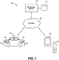
- FIG. 1 depicts an exemplary system 100 that can include one or more actions and/or feedback in response to a deviation in the system, such as a leak or milk flow, detected during operation.
- the system can distinguish between leaks of various sizes based on a signal analysis, and can enable a system action and/or feedback based on the size of the leak detected.
- the system 100 can further support various functionalities associated with an improved milk extracting system, or breastmilk expression system, such as a breastpump system, compression system, or any other suitable system for expressing milk, and various devices and components that can be associated therewith that improve ease of operation and/or feedback experienced during operation of the system.
- FIG. 1 depicts certain connectable entities, components, and devices, it should be appreciated that any additional or alternate entities and components can be incorporated into the system, as desired, to achieve a variety of functional advantages, examples of which are set forth in accordance with the principles herein.
- the system 100 includes a suitable breastmilk expression system, such as a breastpump system 110, an electronic device 105 that can be selectively connected to the breastpump system 110, and a processing server 115 that can be selectively connected to either or both of the breastpump system 110 and the electronic device 105.
- a suitable breastmilk expression system such as a breastpump system 110
- an electronic device 105 that can be selectively connected to the breastpump system 110
- a processing server 115 that can be selectively connected to either or both of the breastpump system 110 and the electronic device 105.
- the electronic device 105 may be any type of electronic device capable of computation and engaging at least one or a plurality of network communications such as, for example, a television, smartphone, notebook computer, tablet, phablet, GPS (Global Positioning System) or GPS-enabled device, printer, smart watch, smart glasses, smart bracelet, wearable electronic device, PDA (personal digital assistant), pager, computing device configured for wireless communication, and/or the like.
- the electronic device 105 may be operated by a user 106 or, in some implementations, may be operated autonomously by processing logic and/or various sensors.
- the electronic device 105 may include a user interface configured to display certain information and receive selections and inputs from the user 106. Further, the electronic device 105 is capable of supporting a communication platform, such as a dedicated application or other type of software (generally, an "application").
- a communication platform such as a dedicated application or other type of software (generally, an "application").
- the user 106 may interface with the application via the user interface to make selections, input data, initiate or facilitate communications with other components of the system 100, and/or perform other functions.
- the application may be a breastpumping application that includes functionalities associated with recording data locally with the device 105 before, during, and/or after a breastpumping session with the breastpump system 110.
- the breastpump system 110 may be a mechanical device including various components configured to extract milk from the breasts of a lactating woman.
- the breastpump system 110 may use suction to act on the nipples of the breasts within a set of breastshields 107, 108, or milk can be extracted by compressive force, or by other suitable alternatives.
- the suction achieved using various extraction methods may mimic an infant's sucking action, whereby the suction causes milk within the breast to evacuate into a set of bottles 103, 104, or other suitable collection container for collection.
- the breastpump system 110 may be of any type, such as a piston pump which may draw a volume displacement mechanism, such as a piston, through a cylinder to create suction, a rotary vane pump which may use a cam with retractable vanes to create suction, a diaphragm pump which may use a volume displacement mechanism in the form of a diaphragm acted on by a lever to create suction with each stroke, or another type of pump, compression device, or other milk extraction device.
- a piston pump which may draw a volume displacement mechanism, such as a piston, through a cylinder to create suction
- a rotary vane pump which may use a cam with retractable vanes to create suction
- a diaphragm pump which may use a volume displacement mechanism in the form of a diaphragm acted on by a lever to create suction with each stroke
- Another type of pump, compression device, or other milk extraction device such as a cylinder to create suction
- a rotary vane pump
- the breastpump system 110 may include a user interface 109 configured to display certain information and receive selections and inputs from a user.
- the user may enter various operation parameters for the breastpump system 110 via the user interface 109.
- the user may initiate or end a breastpumping session, activate or mute feedback sounds, enter a goal time and/or a suction level for a breastpumping session, and/or the like.
- the user interface 109 may also display certain parameters associated with its operation including, for example, an elapsed time or time remaining for a breastpumping session, a suction level, a current time, a status for a breastpumping session (e.g., active, paused, error), warning or error conditions (e.g., leak detected), and/or other information.
- certain parameters associated with its operation including, for example, an elapsed time or time remaining for a breastpumping session, a suction level, a current time, a status for a breastpumping session (e.g., active, paused, error), warning or error conditions (e.g., leak detected), and/or other information.
- the user interface 109 may support a combination of visual and audio feedback throughout a breastpumping session to help guide the user during a pumping session.
- the visual, tactile and/or audio feedback may be used to indicate an error, a "go no further" condition, or that the breastpump system 110 is ready to operate.
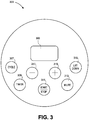
- FIG. 3 depicts a more detailed view of a user interface 309 of a breastpump system, such as the user interface 109 as described with respect to FIG. 1 .
- the user interface 309 is merely exemplary, and may include additional or alternative content, selections, shapes, sizes, and/or the like.
- the user interface 109 may include a set of selections that enables a user to operate the breastpump system and facilitate certain functionalities of the breastpump system. Each of the set of selections is selectable by the user of the breastpump system to cause the breastpump system to perform a corresponding action or function.
- the user interface 309 may include a start/stop selection 311 and a timer selection 309. Selection of the start/stop selection 311 by the user causes the breastpump system to start operation if the breastpump system is currently stopped or paused, or stop/pause operation if the breastpump system is currently operating. Selection of the timer selection 309 by the user may enable the user to enter a timeout period for operation of the breast pump system.
- the user interface 109 may include a display 305 (e.g., an LED display or an LCD display) that displays the timeout period that the user may set via the timer selection 309.
- the set of selections may further include a "+" selection 319 and a "-" selection 317 which the user may select in coordination with setting and/or modifying the timer to respectively add time to the timeout period or remove time from the timeout period.
- the set of selections may further include a cycle selection 307 that, when selected by the user, causes the breastpump system to toggle between or among various breastpump system operating cycles. Additionally, the set of selections may include a mute selection 313 and a let down selection 315. Selection of the mute selection 313 by the user may cause the breastpump system to mute (or unmute, if the breastpump system is currently muted) any audio output, including chimes, beeps, tones, and/or the like. Selection of the let down selection 315 may cause the breastpump system to enter (or exit) a "let down" mode that may simulate an infant's sucking pattern/rate to stimulate let-down reflex.
- the breastpump can provide numerous user inputs and various types of feedback, including directive feedback, if desired, to the user via a suitable user interface, such as the interface illustrated in Figure 3 .
- a user can select a button on the user interface 109, or talk to the pump using voice recognition technology, which may cause the breastpump system 110 to generate a sound, tone, vibration or some other form of haptic feedback, unless the breastpump operating state prohibits the feedback, for example when the device is mute.
- Voice recognition can be achieved as discussed in U.S. Patent No. 8,216,178 , of common ownership.
- the breastpump system 110 may generate sounds for any or all of the following conditions, or other conditions as desired: selection of the "+/-" buttons, a timer at zero, a timer at max time; when a "call" alert is determined and/or displayed to indicate the need to call customer service, when a leak is detected; selection of the power up button, selection of a pattern or when the user has exceeded a maximum or minimum vacuum limit available, when the timer has a certain amount of time remaining, and when the timer has expired.
- the breastpump system 110 further supports various visual feedback that may be in combination with the audio feedback.
- the breastpump system 110 may display a charging indicator when the breastpump system 110 is connected to external power.
- the breastpump system 110 may support backlighting for one, some, or all audio cues. For example, when the breastpump system 110 generates an alert sound, the breastpump system 110 may display an amber color; and if the breastpump system 110 then switches back to a normal state after an alert, the breastpump system 110 may cease the alert sound and the display of the amber color.
- various features are capable of being enabled or disabled based on breastpump operating state.
- Visual, audio, or haptic cues can be used to indicate the enabled or disabled state of the input feature.
- the breastpump system 110 may discontinue illuminating the plus sign and may generate an audio cue indicating that a higher suction level is not available.
- the breastpump system 110 may discontinue illuminating the minus sign and may generate an audio cue indicating that a lower suction level is not available.
- the suction levels indicated by the breastpump system 110 may represent a percentage of a selected nominal curve.
- the suction levels may be tied to other linear or non-linear curves, such as a bell curve, where the change amount for the levels may be linear or non-linear.
- the user of the breastpump system 110 may be the user 106. In other scenarios, the user of the breastpump system 110 may be a user other than the user 106.
- the system of FIG. 1 depicts a single electronic device 105 and a single breastpump system 110, it should be appreciated that the system 100 may include multiple amounts and types of electronic devices and/or breastpump systems.
- the system 100 may further include a processing server 115 that may include any combination of hardware and software components associated with any individual, group of individuals, company, corporation, or other type of entity.
- the processing server 115 may be associated with any or all of a manufacturer, retailer, or servicer of the breastpump system 110.
- the processing server 115 may be associated with a health care institution such as a hospital or clinic.
- the processing server 115 may include or be connected to a database 112 or storage that is configured to store certain information and data.
- the database 112 may include one or more forms of volatile and/or non-volatile, fixed and/or removable memory. Further, the database 112 may be contained in a single location (e.g., on the same premises as the processing server 115) or distributed across multiple locations.
- the system 100 may further include one or more networks 120 configured to facilitate communications between and among the breastpump system 110, the electronic device 105, and the processing server 115.
- the network(s) 120 can facilitate any type of data communication via any standard or technology.
- the network(s) 115 may support various short range communications between the electronic device 105 and the breastpump system 110.
- the network(s) 120 may also support any wired connection between and among the components of the system 110.
- each of the electronic device 105 and the exemplary breastmilk expression system, or breastpump system 110 may generate or collect data or information and communicate the data or information to the other entities of the system 100 via the network(s) 120.
- the electronic device 105 and/or the breastpump system 110 may communicate any generated or collected data to the processing server 115 via the network(s) for storage on the database 112.
- the electronic device 105 and the breastpump system 110 may exchange operation commands via a short range communication, thus enabling remote operation of the breastpump system 110 by the electronic device 105.
- a user may manually input data or make various selections into the electronic device 105 and/or the breastpump system 110 (e.g., via the respective user interfaces).
- Each of the electronic device 105 and the breastpump system 110 may be configured with a memory to locally store various data and information.
- the electronic device 105 is capable of supporting a breastpumping application that includes functionalities associated with recording data before, during, and/or after a breastpumping session with the breastpump system 110.
- the user 106 or breastpump system 110 may communicate interactively with the application to make selections, input data, initiate or facilitate communications with other components of the system 100, and/or perform other functions via the electronic device 105 or the breastpump system.
- the user 106 or breastpump system 110 may input the volume of milk collected during a breastpumping session; the time, date, and location of the breastpumping session; the duration of the breastpumping session; a frequency of use of the breastpump system 110; performance data related to the breastpump system 110; the suction level(s) used during the breastpumping session; and/or other data.
- the breastpump system 110 may offer various device settings and may enable the user 106 to select certain levels for the settings. For example, the user 106 may prefer a certain goal time, a certain suction level, and/or other settings.
- the preferred settings for operation of the breastpump system 110 by the user 106 may be compiled into a set of configuration settings for the user 106.
- the electronic device 105, and/or the breastpump system 110 may be configured with persistent storage capable of storing the set of configuration settings for the user 106.
- the breastpump system 110 may transmit, to the electronic device 105, settings of the breastpump system 110 corresponding to a current or completed breastpumping session by the user 106, where the electronic device 105 may store the settings as a set of configuration settings for the user 106. Accordingly, for subsequent uses of the breastpump system 110 or any other breastpump by the user 106, the electronic device 105 may transmit the set of configuration settings for the user 106 to the corresponding breastpump prior to the user 106 starting a breastpumping session. Upon receipt of the set of configuration settings, the corresponding breastpump may automatically configure its settings. In this regard, the user 106 may not need to manually adjust the breastpump system 110 before each pumping session. This may be useful in situations in which there may be multiple available breastpumps, if the user 106 purchases a new breastpump, or if the user otherwise wishes to use a breastpump that she has yet to use under her most recent configuration selections.
- the communications between the electronic device 105 and the breastpump system 110 may be facilitated according to various techniques and channels.
- the electronic device 105 and/or the breastpump system 110 may support an application programming interface (API) via which the electronic device 105 and/or the breastpump system 110 may request, retrieve, and send data including user feedback and alerts, such as a leak detection alert back and forth between the electronic device 105 and the breastpump system 110.
- API application programming interface
- the communications may also be "push" where either the electronic device 105 or the breastpump system 110 sends data to the other component, or "pull” where either the electronic device 105 or the breastpump system 110 requests data from the other component.
- the electronic device 105 may automatically send the set of configuration settings to the breastpump system 110.
- the breastpump system 110 may request the set of configuration settings from the electronic device 105.
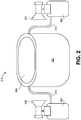
- the breastpump system 210 may include a breastpump housing 201 portion as well as a "kit” or portable components.
- the breastpump housing 201 can house internal components such as a powering component (e.g., a motor), and a mechanism for generating pressure to extract milk (e.g., a piston within a cylinder or other suitable mechanism).
- the housing can also incorporate various external components, such as a user interface 209, a plug or other interface to a power source, and a set of batteries or battery pack that can be connected externally, or internally if desired.
- the kit may include a set of breastshields 207, 208, a set of bottles 203, 204, tubing components 213, 214, as well as other components not depicted in FIG. 2 including membranes, diaphragms, valves, and/or the like. It should be appreciated that additional or alternative components for the breastpump housing 201 and the kit of the breastpump system 210 are envisioned.
- a user of the breastpump system 210 may disconnect the components of the kit from the breastpump housing 201 for purposes of cleaning or transporting the kit.
- the kit further enables the user to use a different breastmilk expression system or breastpump other than the breastpump system 210 to complete a breastpumping session.
- the user may have one breastpump system at home and another breastpump system in the office.
- the kit may have a unique identification that may serve to distinguish the kit from other kits belonging to other users, and help to avoid unnecessary leak alerts that can occur during operation.
- the kit may locally store or secure an alphanumeric or graphic identification that is detectable by electronic components associated with the breastpump system 210, or incorporated into the breastpump housing 201.
- the kit may be equipped with an NFC tag that stores the identification and that is readable by an NFC tag reader incorporated into the breastpump housing 201.
- the kit may be equipped with any suitable device that stores identification information, such as a bar code or any other device.
- the breastpump housing 201 may include an imaging sensor capable of capturing an image of the kit identification. It should be appreciated that additional or alternate components may store or otherwise include or display the kit identification.
- a user may manually enter the identification of the kit using the breastpump interface 209 or into an associated electronic device.
- the kit ID can be provided within a removable memory device and uploaded to associated electronic devices or servers by connecting the memory device to a base as described in European Patent 14 158 098.5 of common ownership, incorporated herein in its entirety.
- the kit identification can enable a variety of improved applications and functionalities associated with the breastpump system 210 and entities associated therewith.
- the kit ID can provide default configuration settings to optimize pump performance to match the kit.
- the breastpump system 210 may initiate certain functionalities or communications in response to detecting and identifying a kit that is connected thereto.
- the breastpump system 210 may connect to an electronic device (e.g., the electronic device 105) to retrieve user profile data that corresponds to the kit identification.
- the breastpump system 210 may retrieve the user profile data from a dedicated breastpumping application installed on the electronic device.
- the breastpump system 210 may locally or centrally store the user profile data that corresponds to the kit identification.
- the user profile data may include a set of configuration settings that are preferred by the associated user.
- the breastpump system 210 may identify the set of configuration settings from the user profile and may automatically implement the set of configuration settings.
- the kit identification enables the user to efficiently and effectively configure different breastpumps according to preferred settings.
- the different user profiles may further include data related to the operation and performance of the breastpump system 110 and/or the kit ID by the corresponding user. The user profile data can therefore enables the breastpump system 110 and/or the electronic device 105 to accurately assess/analyze operation of the breastpump system 110 and/or the kit according to the user profile.
- the breastpump system 110 may store certain baseline operation data that the breastpump system 110 may analyze during operation to detect fault conditions or errors. For example, baseline operation data associated with a pressure detected by a pressure sensor of the breastpump system 110 may be used to determine that a fault leak condition exists. In particular, the pressure from a pressure sensor may be below a baseline value by a threshold error coefficient for a threshold period of time. However, if profile data for example User A indicates that use of the breastpump system 110 by User A consistently results in lower than average pressure values, then the breastpump system 110 may adjust the leak condition values to account for the difference. In particular, the breastpump system 110 may modify its baseline values, error coefficients, or other data to account for the operating differences.
- the exemplary breastpump system 110 constructed in accordance with the principles herein may avoid erroneously triggering a fault condition resulting from lower pressure values when a fault leak condition does not actually occur.
- the user profiles may include additional parameters associated with operation of the breastpump system 210 including, for example, expressed milk volume, average pump time, average suction level, and/or others.
- the user profile data may also be beneficial in a clinical setting such as a hospital, clinic, or other type of health care institution.
- a patient may have an associated electronic medical record (EMR) and/or electronic health record (EHR), where each of the EMR and the EHR may include a patient medical history that may be referenced and used for diagnosis and treatment.
- EMR electronic medical record
- EHR electronic health record
- the EMR and/or the EHR of a patient may be included with the user profile of the patient or may be separate from the user profile of the patient.
- a kit identification of a particular user may additionally identify a corresponding EMR and/or EHR for the user.
- the breastpump system 110 may identify the patient associated with the kit identification and connect to a server associated with the health care institution to retrieve data associated with the patient.
- the breastpump system 110 may retrieve a set of configuration settings for the breastpump system 110 that are preferred by the patient or a clinician, and may configure itself accordingly.
- the breastpump system 110 may retrieve at least a portion of the EMR and/or EHR corresponding to the patient. It should be appreciated that the breastpump system 110 may be configured to comply with HIPAA and/or any other applicable healthcare-related laws or regulations that govern which patient data may be made available. The breastpump system 110 may further be configured to update any relevant data (e.g., the set of configuration settings and/or any relevant portions of the EMR and/or EHR, or kit ID) during and/or after a breastpumping session, and may communicate the updated data to the server associated with the health care institution. Accordingly, when the breastpump system 110 reconnects to the server (e.g., before a subsequent breastpumping session), the breastpump system 110 may retrieve relevant updated data.
- any relevant data e.g., the set of configuration settings and/or any relevant portions of the EMR and/or EHR, or kit ID
- the breastpump system 110 may retrieve relevant updated data.
- the user 106 may have or wish to use a specific breastpump, such as a breastpump that is already configured according to the preferences of the user 106.
- a specific breastpump such as a breastpump that is already configured according to the preferences of the user 106.
- each of the breastpumps in the location may emit a connection signal, which may be a unique signal or a signal transmitted over a unique channel or frequency, detectable by the electronic device 105, where the electronic device 105 may measure the signal strength of each connection signal (e.g., in mV/m) to determine the preferred breastpump of the user 106.
- the preferred breastpump may be the breastpump that is closest to the user 106 and thus the breastpump that emits the connection signal having the highest received signal strength.
- the breastpump system 110 may experience a fault, error, breakdown, or the like, which may prompt its user to contact customer service or support. These situations may be tedious and time consuming to the user because the user may need to troubleshoot the breastpump system 110 and/or may want or need to order/request a new or replacement breastpump, even if there is no mechanical defect in the breastpump system 110. Similarly, a manufacturer, retailer, or servicer of the breastpump system 110 may need to dedicate resources for providing support to the users. As a result, a goal of a manufacturer, retailer, or servicer of the breastpump system 110 may be to reduce the number of situations in which a user of the breastpump system 110 may need service or support for the breastpump system 110.
- the present embodiments therefore provide various techniques to preemptively identify circumstances or situations which may cause a user of the breastpump system 110 to contact customer support or service.
- the present embodiments provide a means of distinguishing between conditions that are in fact faults and those that do not require additional support or service but merely user intervention, such as certain leaks that may arise during a pumping session.
- certain components of the breastpump system 110 may be configured with a set of sensors.
- the set of sensors may include one or more pressure sensors disposed at any location within or along the tubing 113, 114 of the breastpump system 110 (or another portion of the breastpump system 110), where the pressure sensors are designed to detect the amount of pressure within the tubing 113, 114.
- the pressure sensors can be positioned anywhere within an air fluid path that is directly or indirectly connected to the tubing. It should be appreciated that additional sensors are envisioned, such as overflow sensors, bacteria sensors, vibration and audio sensors, and/or others.
- the breastpump system 110 may include a controller or processor configured to analyze data from the set of sensors and make various determinations based on the sensor data.
- the controller of the breastpump system 110 may compare data collected from the set of sensors to baseline data in an attempt to identify potential or impending problems or issues with the breastpump system 110.
- the controller may be a proportional-integral-derivative (PID) controller which may employ a control loop feedback mechanism to calculate an error value or coefficient representing the difference between a measured process variable and a desired set point. It should be appreciated that other types of controllers are envisioned.
- PID proportional-integral-derivative
- the controller may compare the error coefficient to a threshold value.
- the controller may account for a time metric in performing the error coefficient analysis in order to gauge any decline in performance over time and/or the current performance for a corresponding time period. If the error coefficient meets or exceeds the threshold value for a certain amount of time, or if the data indicates a gradual decline in performance, then the controller may deem that the breastpump system 110 (or a portion thereof) is faulty, may need immediate repair or replacement, or may need repair or replacement at a future time. Accordingly, the controller may facilitate various preemptive actions that may negate the need for the user to contact service or support.
- the controller may identify, based on the type of sensor data and the error coefficient analysis, that a certain part or component of the breastpump system 110 is faulty and therefore may need to be replaced.
- the controller may request an entity (e.g., a manufacturer, retailer, or servicer of the breastpump system 110) to contact the user to arrange for a replacement part or component.
- an entity e.g., a manufacturer, retailer, or servicer of the breastpump system 110
- a service individual may call the user to inform the user of the potential issue and arrange for shipment of the replacement part or component.
- the controller may automatically generate an electronic communication (e.g., e-mail, text message, push notification) and send the electronic communication to the user (e.g., to the electronic device 105) to inform the user of the potential issue and arrange for shipment of the replacement part or component.
- an electronic communication e.g., e-mail, text message, push notification
- the controller may determine that one or more parts of the breastpump system 110 may need replacement, or may determine that the entire breastpump system 110 may need replacement. This determination may be made, for example, based on the sensor or operation data collected from the various sensors as well as the error coefficient analyses.
- the amount of time and effort that the user would otherwise spend on troubleshooting or replacing the breastpump system 110 may be reduced or eliminated. Additionally, the amount of support resources needed by the manufacturer or retailer may be reduced, which may result in a cost savings passed down to the users or customers.
- a dedicated breastpumping application of the electronic device 105 may interface with additional applications installed on the electronic device 105 (e.g., via an operating system of the electronic device 105).
- the user 106 may configure the electronic device 105 to cause the breastpump system 110 to stop or pause operation if certain conditions are detected. For example, if the electronic device 105 receives an incoming communication (e.g., phone call, text message, e-mail), then the electronic device 105 may automatically cause the breastpump system 110 to pause operation, or to place the breastpump 100 into a "quiet" mode in which audio cues of the breastpump system 110 may be muted. In some embodiments, the electronic device 105 may prompt the user 106 to select whether to pause operation of the breastpump system 110 in response to various detected conditions.
- an incoming communication e.g., phone call, text message, e-mail
- the electronic device 105 may also analyze data collected or sensed by various sensors to control certain operations and functionalities.
- the electronic device 105 may be equipped with various sensors including an imaging sensor(s), a barometer, an altimeter, a location module (e.g., a GPS chip), an accelerometer, a gyroscope, an audio module, including a microphone and speaker(s), and/or other sensors.
- the electronic device 105 may analyze any collected sensor data to determine an environment of the electronic device 105 and cause the breastpump system 110 to modify its operation accordingly, such as automatically increasing the volume of the breastpump system 110 audio during operation when the environmental noise is so high that audio feedback signals, such as leak alerts, cannot be heard during operation .
- the electronic device 105 may identify its current location (e.g., via GPS coordinates) and may examine a map database to identify a venue or location where the electronic device 105 may be located, and correspondingly where the breastpump system 110 may be located.
- a user may have a user profile that indicates a home address and a work address, where the electronic device 105 may determine from the location data whether the electronic device 105 is located at home or at work.
- the electronic device 105 may appropriately configure the breastpump system 110 according to a "home configuration" that the user prefers at home or to a "work configuration" that the user prefers at work.
- the electronic device 105 may transmit a corresponding set of configuration settings to the breastpump system 110 based on identified location.
- the electronic device 105 may be configured to estimate an ambient pressure based on alternative or additional data. For example, the electronic device 105 may determine its traveling velocity and if the traveling velocity exceeds a certain threshold (e.g., 250 miles/hour), then the electronic device 105 may deem that it is in flight and that its ambient pressure is lower than normal operating air pressure for the breastpump system 110. Accordingly, the electronic device 105 may cause the breastpump system 110 to modify its operation accordingly, such as by increasing or decreasing certain baseline operation data, error coefficients, and/or other data.
- a certain threshold e.g. 250 miles/hour
- the electronic device 105 may also be configured to interface with an additional electronic device to retrieve relevant data and control operation of the breastpump system 110 accordingly.
- the electronic device 105 may interface with a "wearable" device with stored activity data for its wearer (e.g., the user 106).
- the activity data may include, for example, movement data (e.g., in the form of "steps"), blood pressure readings, heart rate readings, and/or the like.
- the activity data may also have an associated timestamp such that when the electronic device 105 retrieves the activity data, the electronic device 105 may determine a current or recent activity state of the user.
- the electronic device 105 may cause the breastpump system 110 to modify various operation parameters accordingly. For example, if the electronic device 105 indicates that the user has been active recently (e.g., has just finished an exercise session), then the electronic device 105 may increase (or decrease) a timeout parameter of the breastpump system 110, may increase (or decrease) a suction level of the breastpump system 110, and/or may modify other operation parameters, error coefficients, and/or the like.
- the electronic device 105 or breastpump system 110 may record data associated with an external audio device to identify a condition of which the user 106 may want to be alerted.
- a microphone of the electronic device 105 may detect audio that is output from a baby monitor or similar device, where the electronic device 105 may analyze the audio and determine that a baby may need to be attended to.
- the electronic device 105 may detect sound/audio directly from the baby. The electronic device 105 may accordingly cause the breastpump system 110 to automatically pause operation which may enable the user 106 to attend to the baby, or at least prompt the user with an audio and/or visual cue to check whether the user would like to pause operation.
- the microphone of the electronic device 105 may detect audio associated with operation of the breastpump system 110 and/or components thereof, and analyze the audio to determine an operating condition of the breastpump system 110. Based on the determination, the electronic device 105 may then modify operation of the breastpump system 110 accordingly. For example, the electronic device 105 may analyze detected audio and determine that the audio includes patterns consistent with a leak in the tubing 113, 114 of the breastpump system 110. As a result, the electronic device 105 may cause the breastpump system 110 to pause or stop operation, to modify operation (e.g., increase pump level) to account for the leak, or to modify operation in some other manner.
- modify operation e.g., increase pump level
- the electronic device 105 may be configured to connect to a printer device via any type of wired or wireless connection.
- the printer device may be a standard printer, a "pocket" printer that offers more portability, a label printer, or any other type of device capable of printing graphics or text on paper or similar physical media.
- the electronic device 105 or breastpump system 110 may generate a unique identification (e.g., an alphanumeric code or graphic) that corresponds to mom, bottle, pump and the breastpumping session. Additionally, the electronic device 105 may upload the unique identification and the various data related thereto to the processing server 115 for storage in the database 112. The electronic device 105 may further transmit instructions and imaging data to the printer device to cause the printer device to print out a label that corresponds to the breastpumping session.
- a unique identification e.g., an alphanumeric code or graphic
- the label may include or indicate the unique identification generated by the electronic device 105, and may further include or indicate some or all of the various data associated with the breastpumping session.
- the label may enable a user to access the unique identification and/or the various data (e.g., such as if the label is embodied as a QR code or other type of bar code).
- the user 106, the printer device, or another component may then manually or automatically apply the label to a corresponding bottle (e.g., one of the bottles 103, 104) that contains the milk collected during the breastpumping session.
- a user may access or review some or all of the various data associated with the breastpumping session via the label that was printed.
- a nurse may scan a label on a bottle and access the corresponding unique identification using a scanner or other electronic device. The scanner may then retrieve, using the unique identification, the various data associated with the corresponding breastpumping session, such as by retrieving the various data stored on a server in a hospital. The nurse may then use the retrieved data to properly or accurately administer a feeding, such as by using the freshest milk, distinguishing the bottle from bottles belonging to other mothers, or making other determinations.
- the labels and associated breastpumping session information may enable moms to distinguish their bottles from those of other moms (e.g., such as in a workplace environment), or may enable caregivers to distinguish bottles intended for certain babies (e.g., such as in a daycare).
- the breastpump system 110 there may be conditions which affect the performance of the breastpump system 110 and/or the amount of milk collected. These conditions include: the leak of fluid into or out of the system control volume, the occlusion of the portions of the system intended to be in fluid communication, attachment of system elements which result in an excessively small or large control volume.
- There are various categories or causes for leaks including: the breastshield 107, 108 not being secured to the breast(s); the user 106 is single breastpumping but the breastpump system 110 is not set for single pumping; a vacuum is almost achieved but there is a leak in the system, such as when the tubing 113, 114 is slightly displaced from the connection port; or the breastpump system 110 is broken.
- Occlusions of the system may occur when tubes are kinked or crushed, etc. Excessive or inadequate control volume can occur if, e.g. breast shields which are not intended for use with the breastmilk expression system are utilized and are of a different volume. Any of these categories or causes may result in a less than optimal breastpumping session and possibly even a service call because the user may think that there is a problem with the breastpump system 110.
- the current embodiments support various components and calculations, where required, to accurately assess leak characteristics and enable associated responses.
- the current embodiments can be configured to distinguish between the type of leak detected by a leak detection circuit, and a specific response to address the leak detected using a response circuit.
- the response generated by the response circuit can include providing feedback regarding the magnitude and type of the leak to the system, the user, or both the system and the user. Further, the current embodiments can employ solutions enabled by the response circuit for promptly addressing a variety of leaks, either directly or indirectly, once detected.
- the path of fluid communication between the breastpump system 110, and the breast may be occluded, as in kinked tubing, 113,114.
- the current embodiments support various components and calculations, where required, to accurately assess whether an occlusion is present.
- the current embodiments can be configured to distinguish an occlusion from leaks and to provide feedback regarding the magnitude and nature of the occlusion. Further, the current embodiments can employ solutions for promptly addressing a variety of occlusions, either directly or indirectly, once detected.
- the current embodiments enable the user to effectively and efficiently intervene with feedback selectively provided via the response circuit throughout the pumping session so that the user may eliminate or mitigate leaks or occlusions without having to take the extra time to deduce whether there is something wrong with the breastpump system 110.
- a leak may be detected prior to normal breast pumping operation. This may be achieved by closing the breastpump system from the atmosphere and conducting various operations. The closing of the breastpump system may be accomplished by, for instance, plugging the breastshields, closing a valve between the pump and the breastshield either manually or automatically, as by a solenoid valve, cinching the tubing leading to the breastshields. Once the system is isolated from the atmosphere, the pump can be caused to displace a known quantity of volume and then the vacuum measured. If there is no leak or an adequately small leak, a predictable vacuum will be achieved in the breastpump system. This level of vacuum will be dependent on the original atmospheric pressure in the system, the original volume, and the volume after displacement.
- the pump could be made to achieve a particular vacuum and the displaced volume can be detected in order to achieve that vacuum. Leaks may be introduced after re-configuring the system for normal use. Further, leaks may develop between reconfiguring the pump and conducting normal breastpumping.
- the breastpump can control to a fixed vacuum during normal breastpumping, and determine the rate of displacement required to achieve the fixed vacuum. This rate of displacement will be proportional to the leakage rate.
- the breastpump can assume a fixed displacement which has generated a vacuum in the pump and observe the rate of change of the vacuum. If the pressure is increasing over time, the leak rate will be associated with the rate of increase of pressure at a given moment. The leak rate will depend on the atmospheric pressure and the original volume of the pump system.
- the breastpump system 110 is configured to determine leaks while the breastpump system 110 is operating, including intermittent leaks where the breastpumping session may be able to continue to operate in an effective manner.
- the breastpump system 110 may estimate a volume or degree of the leak by calculating the rate at which air/fluid enters the system and how it relates to the vacuum and piston displacement.
- the breastpump system 110 is able to estimate the attached volume and leak size by estimating the state of the system and making comparisons to measured state variables, and/or stored information based on the pumping configuration, e.g. an expected minimum pressure, a pressure vs. time profile, or an intended displacement.
- the state of unmeasured variables may be then updated to minimize the error in the estimate when compared to the measurements, resulting in an estimate of the magnitude of the leak and the attached volume.
- the breastpump system 110 is therefore able to identify a likely source of the leak as well as adjust operation of the breastpump system 110 accordingly so as to counteract the leak.
- the breastpump could be controlled to a specific volume simultaneous with estimation of leak and pressure parameters
- the breastpump could be controlled to a specific pressure combined with the estimation of leak and volume parameters.
- the embodiments described herein differ from conventional leak detection techniques in that the embodiments herein are capable of distinguishing between different types of leaks, and/or sizes of leaks, and based on the detected nature and/or size of the leak, a controller can operate the breastpump to either perform a system change, provide feedback to the system, the mom using the system, or both, or perform a system change and provide feedback.
- the system can continuously or substantially continuously deduce the difference between the required volume displacement to generate the desired vacuum curve and the volume displacement required to generate the desired vacuum curve in a non-leaking breastpumping system.
- the embodiments may estimate parameters for the original system volume and the leak magnitude based on the observed vacuum at a particular displaced volume.
- the embodiments disclosed herein may therefore permit the user to customize the user's experience by continuously analyzing the system for leaks throughout, or during discrete or random intervals during the breastpumping session, and dynamically notifying the customer of a distinct detected leak with an appropriate message, sound, or internal corrective measure.
- This enables the breastpump system 110 to deduce when the user is having a physiological response that is not a leak, and enables the breastpump system 110 to delay a shut off in the event that the user is not yet connected by determining, via sampling or another suitable method, that the user has not yet connected to the breastpump system 110 after the breastpump system 110 is activated.
- An event such as a loss of seal between the breast shield and the breast could also be detected as a type of leak that would cause an immediate response, such as a cessation of operation and a return of the vacuum source to a home position.
- the user of the breastpump system 110 can input the size of the breastshields 107, 108, or the breastpump system 110 may automatically identify this information from a connected device or accessory and store in its settings.
- the breastpump system 110 may include one or more of the following: a pressure switch, a two setting pressure switch, a relative pressure sensor, an absolute pressure sensor, or the ability to detect a load on the motor.
- the breastpump system 110 may determine vacuum from detecting a force or strain in a volume displacement device, a change in temperature, or a motor armature current, or other.
- a controller of the breastpump system 110 may determine whether there is a leak by determining the displaced volume of the pump, estimating or determining the original volume of the pump kit system, determining the vacuum over time, and solving for the difference between the current volume and the volume that would produce the measured vacuum.
- the controller may cause the user interface 109 to indicate the leak, such as by activating a light, displaying an error (e.g., "ERR"), sounding a tone, or via other audio, visual cues, or other feedback.
- the controller may continue operation of the breastpump system 110 while the user mitigates or eliminates the leak, such as via incorporating a threshold timeout. Additionally, the controller may determine that the leak is milk entering the system, as discussed in detail below.
- the controller may continuously determine if there is a leak by continuously determining the atmospheric pressure, displaced volume, initial volume (which may be estimated or determined from any suitable means such as the size of the breastshields, or determined from information stored with the breastshields or system configuration, or any other suitable means) and vacuum.
- the controller may consistently and periodically perform this determination. For example, the controller may constantly perform this determination every four (4) ms. In another implementation, the controller may repeatedly perform this determination a set number of times after a set period of time has elapsed. In other words, there may be dwell times between determinations. For example, the controller may perform this determination a total of five (5) times every three (3) ms, then wait a total of fifteen (15) ms, then perform this determination an additional five (5) times every three (3) ms, then wait another fifteen (15) ms, and so on, in what may be considered a "train" of determinations. It should be appreciated that the amount of time between determinations and the amount of time during which the controller does not perform any determinations may vary and may also be configurable or be random.
- the controller may determine both the size of the leak as well as an operation to perform based on the size of the leak. In some scenarios, the size of the leak may be below a threshold value and the controller may therefore not take any action.
- the leak may meet or exceed a threshold value and the controller may take various actions including pausing or stopping the pump, increasing or decreasing a suction level, indicating the leak via the user interface 109, maintaining operation or idling while enabling the user to mitigate or eliminate the leak, applying more or less torque, increasing or decreasing a current level, causing the user interface 109 to indicate the leak, or performing other actions.
- the controller may also collect and analyze subsequent data or readings to determine whether the leak has been corrected or otherwise adequately mitigated.
- the controller may account for operation data within a user profile of the user of the breastpump system 110 when determining whether there is a leak.
- operation of the breastpump system 110 by certain users may result in certain piston positions, or displacements of the vacuum generating member, and vacuums that, in "normal" usage, may correspond to a leak in the breastpump system 110.
- these piston position and vacuum may result in non-leak operation of the breastpump system 110. Therefore, the controller may make adjustments to any baseline values, error coefficients, or other variables during the leak determination so that the controller does not erroneously trigger the detection of a leak.
- a new and useful feature to include in a breastmilk expression system would be the ability to measure at least one of milk volume, flow rate, and milk ejections in a non-contact manner. Such a solution would minimize the chance of milk contamination, reduce cleaning burdens, and help to simplify the overall user experience of a breastmilk expression system while avoiding added costs of additional sensors in the system.
- a closed loop breastmilk expression system can be utilized to indirectly measure breastmilk output during a pumping session.
- the pump, pump kit, and lactating breast effectively define a closed system, i.e. a control volume
- the pressure-to-volume relationship can be established for a positive displacement system.
- the closed system is a mixed-phase system, wherein a vacuum (partial pressure) is periodically generated via air rarefaction within the control volume that also contains breast milk in a liquid state.
- Breastmilk entering the system is effectively an incompressible substance and remains in a liquid state at the working pressures.
- Expected changes in the working pressure range, both positive & negative, have no appreciable influence on the volume of breastmilk. Therefore, volume occupied by the breastmilk within the system decreases the volume of gas occupying a given control volume.
- the expected vacuum can be compared to the actual vacuum achieved.
- the measured change in volume can approximate the volume of breastmilk collected as an indirect measurement.
- the control volume in a breast pump system is not ideal for indirect milk measurement since it is neither rigid nor stable. This is due to elastic breast tissue and other flexure in the system. The breast tissue may also change in compliance over the course of a pumping session. Other limitations include pressure drops in the system due to flow restrictions and the possible inclusion of flexible membranes or filters (media separation) to prevent milk overflow into the pump. Leaks in the system are also undesirable. These and other factors introduce noise in the system that should be managed to obtain an accurate milk output reading. In addition, small amounts of breastmilk are typically expressed each vacuum cycle. This makes the signal (which is intended to be indicative of milk volume) difficult to discern from the system noise for an indirect measurement approach. While indirect measurement accuracy is limited compared to direct measurement techniques, the practical application does not require high accuracy.
- a closed loop breastmilk expression system of the present disclosure can ascertain milk volume and flow signal information from other undesirable factors such as leaks and other noise in the system.
- the system and methods disclosed herein are presented to improve accuracy.
- breastpump systems evacuate a breastpump kit that expresses a small amount of milk in one cycle from the breast. At the end of the cycle the breastmilk is ejected though a one-way valve (a check valve) into a collection container.
- the collection container is not usually part of the evacuated control volume, in order to minimize the power required for the system and to provide a consistent control volume for consistent application of vacuum since collection container sizes and manufacturers often vary.
- Some systems do evacuate the collection container as well. These systems have a disadvantage in the amount of power required to apply vacuum (due to larger control volume) but the check valve for the vacuum cycle is not restricted to be between the kit and the collection container.
- the following embodiments may be employed to obtain a milk volume measurement.
- the second and third approaches described below are structured to improve the signal/noise ratio compared to the first approach described below.
- a first method of measuring breastmilk volume involves taking a baseline vacuum-displacement cycle(s) reading(s) during the pumping session. This baseline reading would later be used to compare against other cycles to obtain the indirect milk volume measurement. Target cycles would include vacuum displacement where breastmilk is not introduced into the system, such that a baseline control can provide a more accurate comparison.
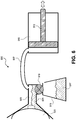
- the system may determine this or the input may in part come from the user - for example as they switch from stimulation to milk expression modes. Volume measurements would be captured over time throughout the pumping session. A typical system configured to use this approach is illustrated in Figure 5 .
- FIG. 6 A second approach is illustrated in FIG. 6 . Since small volumes of breastmilk are typically expressed in each cycle, an improved approach would be to begin to pool (accumulate) the breastmilk in the kit for a plurality of cycles prior to ejecting the breastmilk into the collection container.
- One manner of accomplishing this, in a passively valved system, is to use a baseline vacuum to keep the check valve closed. This baseline vacuum need only be sufficient to overcome the head height pressure of the pooled breastmilk and valve closing forces. Once sufficient breastmilk has pooled, or after a determined number of cycles, the vacuum would return to equilibrium to allow the breastmilk to release into the collection container. In this way the determined change, or delta, of the control volume at the beginning of the accumulation compared to the end can provide a larger value, thereby increasing signal to noise of the system measurement.
- an actively valved system would simply remain closed until it was determined to open the valve. Opening of the valve could occur either manually or automatically (i.e. such as by user intervention, electromechanically, or mechanically). In this exemplary embodiment the system would not necessarily require a baseline vacuum to keep the valve closed & could return to equilibrium each cycle.
- the pump is more efficient as the milk accumulates due to a reduced effective control volume; accumulating milk could be contained in such a way as to warm the nipple; accumulating milk could be contained in such a way as to lubricate the nipple.
- the breastpump system could also accumulate milk in the collection container and compare the delta of an empty collection container at the beginning of a pumping session to that at the end.
- This approach is similar to the second approach, in that it would further increase measurement signal to noise.
- the check valve would not be intermediate to the kit and the collection container, but would instead be located elsewhere in the control volume. This approach requires evacuation of the collection container. While this system requires more power comparatively, it would become more efficient over time as the collection container fills with milk and reduce the effective control volume.
- any of the above-described exemplary approaches to calculate milk volume for an entire pumping session could be used to calculate milk volume for a portion of a pumping session, and could be combined with additional data, such as elapsed time of a pumping session, to determine expression rate, number of milk ejections, duration of milk ejections, and other data points that may be meaningful metrics in evaluating the quality, effectiveness, and/or efficiency of a pumping session.
- the exemplary embodiments enable the detection and computational analysis of milk volume and/or milk flow, modest, manageable leaks, and larger, unacceptable leaks.
- the embodiments further enable a variety of custom settings where tolerance may be allowed for certain leaks for a specified period of time, if desired, or alerts can be generated, as desired, based on milk volume and/or milk flow.
- This enables the breastpump system 110 to avoid certain shut off conditions where the user may not yet be connected, and to incorporate other flexible customized leak, milk volume and milk flow feedback and control.
- the breastpump system 110 is more adaptive to the user and allows for expectations of intended pump operation to be incorporated into the pumping session parameters.
- the breastpump system 110 may provide any collected or determined information to the processing server 115, and the processing server 115 may analyze any received information to determine leak cause frequency, milk output, or other metrics that provide feedback that may lead to potential design enhancements or adjustments to the breastpump system 110 or any components thereof.
- FIG. 4 depicts a method 400 of distinguishing a leak within a breastpump system. It should be appreciated that the method 400 may be performed by the breastpump system itself, and in particular various components of the breastpump system. It should be appreciated that the method 400 is merely exemplary and that additional or alternative functionalities are envisioned.
- the method 400 may begin with a leak detection circuit detecting (block 405) that a leak exists.
- the leak detection circuit may determine (block 410) a size of the leak.
- the leak detection circuit may also transmit (block 415) data regarding the size of the leak to a processor associated with a controller of the breastpump system.
- the processor may determine (block 420) whether the size of the leak exceeds a leak size threshold. In embodiments, a predetermined amount of time may elapse after the processor determines whether the size of the leak exceeds the leak size threshold. After the predetermined amount of time has elapsed, the leak detection circuit may retrieve (block 425) additional leak data (i.e., updated leak data). The processor may compare (block 430) the updated leak data to the prior leak data to determine if the leak has been reduced.
- FIGs. 5-9 illustrate various cross-section views of a breastpump system and its interaction with a user. It should be appreciated that the breastpump system as depicted in FIGs. 5-9 is merely exemplary and that additional or alternative components are envisioned.
- FIG. 5 depicts a breastpump system 500 that may include a kit 505 connected to a pump 510 via tubing 507.
- the kit 505 may be positioned in proximity or secured to a breast 520 of a user.
- the pump 510 may include a piston 512 or plunger that may apply or release a force within the tubing 507 and the kit 505.
- a corresponding force may be applied on the breast 520, and fluid (milk) may be expressed from the breast 520 and may enter the kit 505.
- the breastpump system 500 may further include a collection container 515 that may collect fluid 517 that is expressed from the breast 520.
- a valve 518 may be positioned between the kit 505 and the collection container 515, where the valve 518 may control the transfer of fluid from the kit 505 to the collection container 515.
- FIG. 6 depicts the breastpump system 500 as described with respect to FIG. 5 .
- FIG. 6 illustrates the kit 505 filled with fluid 521 that was extracted from the breast 520.
- the fluid 512 may be maintained in the kit 505 by the valve 518 that is in a closed position (i.e., there is not a clear pathway between the kit 505 and the collection container 515).
- FIG. 7 depicts the breastpump system 500 with the valve 518 in the "open" position (i.e., the position of the valve 518 enables a clear pathway between the kit 505 and the collection container 515). Accordingly, the fluid 521 in the kit 505 as depicted in FIG. 6 may transfer to the fluid 517 in the collection container 515.
- FIG. 8 depicts an alternative implementation of the breastpump system 500.
- FIG. 8 depicts the breastpump system 500 with two valves 518, 523, where the valve 518 may be positioned in relation to the kit 505 and the valve 523 may be positioned in relation to the pump 510.
- FIG. 9 depicts another alternative implementation of the breastpump system 500.
- FIG. 9 depicts a media separation 524 that may be part of the tubing 507. According to embodiments, the media separation 524 may control the suction force within the kit 505.
- the breastpump system 110 may include one or more processors (or controller(s)) as well as a memory.
- the memory may store an operating system capable of facilitating the functionalities as discussed herein as well as a set of applications (i.e., machine readable instructions).
- one of the set of applications may be a leak detection application having a leak detection circuit and a response circuit configured to analyze data to detect leaks and/or facilitate various functionalities for mitigating the leak. It should be appreciated that one or more other applications are envisioned.
- the processor may interface with the memory to execute the operating system and the set of applications.
- the memory may store pressure vs. time profiles, user profiles, various baseline data, and/or other data that the breastpump system 110 may utilize to support the systems and methods.
- Various of the applications may access the memory to facilitate the various applications discussed herein.
- the memory may include one or more forms of volatile and/or non-volatile, fixed and/or removable memory.
- the breastpump system 110 may further include a communication module configured to communicate data via the one or more networks 120.
- the communication module may include one or more transceivers (e.g., WWAN, WLAN, and/or WPAN transceivers) functioning in accordance with IEEE standards, 3GPP standards, or other standards, and configured to receive and transmit data via one or more external ports.
- the communication module may receive, via the network 120, user profile data associated with a user of the breastpump system 110.
- the breastpump system 110 may further include the user interface 109 configured to present information to a user and/or receive inputs from the user.
- the user interface 109 may include a display screen and I/O components (e.g., ports, capacitive or resistive touch sensitive input panels, keys, buttons, lights, LEDs, speakers, microphones).
- I/O components e.g., ports, capacitive or resistive touch sensitive input panels, keys, buttons, lights, LEDs, speakers, microphones.
- the breastpump system 110 may communicate with other hardware or software components within a "cloud" network.
- a computer program product in accordance with an embodiment may include a computer usable storage medium (e.g., standard random access memory (RAM), an optical disc, a universal serial bus (USB) drive, or the like) having computer-readable program code embodied therein, wherein the computer-readable program code may be adapted to be executed by a processor or controller (e.g., working in connection with an operating system) to facilitate the functions as described herein.
- the program code may be implemented in any desired language, and/or may be implemented as machine code, assembly code, byte code, interpretable source code or the like (e.g., via C, C++, Java, Actionscript, Objective-C, Javascript, CSS, XML).
- the computer program product may be part of a cloud network of resources.
- routines, subroutines, applications, circuits or instructions may constitute either software (e.g., code embodied on a non-transitory, machine-readable medium) or hardware or both.
- routines, etc. are tangible units capable of performing certain operations and may be configured or arranged in a certain manner.
- one or more computer systems e.g., a standalone, client or server computer system
- one or more hardware modules of a computer system e.g., a processor or a group of processors
- software e.g., an application or application portion
- a hardware module may be implemented mechanically or electronically.
- a hardware module may comprise dedicated circuitry or logic that is permanently configured (e.g., as a special-purpose processor, such as a field programmable gate array (FPGA) or an application-specific integrated circuit (ASIC)) to perform certain operations.
- a hardware module may also comprise programmable logic or circuitry (e.g., as encompassed within a general-purpose processor or other programmable processor) that is temporarily configured by software to perform certain operations. It will be appreciated that the decision to implement a hardware module mechanically, in dedicated and permanently configured circuitry, or in temporarily configured circuitry (e.g., configured by software) may be driven by cost and time considerations.
- the terms "hardware module,” “processor,” and “controller” should be understood to encompass a tangible entity, be that an entity that is physically constructed, permanently configured (e.g., hardwired), or temporarily configured (e.g., programmed) to operate in a certain manner or to perform certain operations described herein.
- hardware modules are temporarily configured (e.g., programmed)
- each of the hardware modules need not be configured or instantiated at any one instance in time.
- the hardware modules comprise a general-purpose processor configured using software
- the general-purpose processor may be configured as respective different hardware modules at different times.
- Software may accordingly configure a processor, for example, to constitute a particular hardware module at one instance of time and to constitute a different hardware module at a different instance of time.
- Hardware modules can provide information to, and receive information from, other hardware modules. Accordingly, the described hardware modules may be regarded as being communicatively coupled. Where multiple of such hardware modules exist contemporaneously, communications may be achieved through signal transmission (e.g., over appropriate circuits and buses) that connect the hardware modules. In embodiments in which multiple hardware modules are configured or instantiated at different times, communications between such hardware modules may be achieved, for example, through the storage and retrieval of information in memory structures to which the multiple hardware modules have access. For example, one hardware module may perform an operation and store the output of that operation in a memory device to which it is communicatively coupled. A further hardware module may then, at a later time, access the memory device to retrieve and process the stored output. Hardware modules may also initiate communications with input or output devices, and can operate on a resource (e.g., a collection of information).
- a resource e.g., a collection of information
- processors may be temporarily configured (e.g., by software) or permanently configured to perform the relevant operations. Whether temporarily or permanently configured, such processors may constitute processor-implemented modules that operate to perform one or more operations or functions.
- the modules referred to herein may, in some example embodiments, comprise processor-implemented modules.
- the methods or routines described herein may be at least partially processor-implemented. For example, at least some of the operations of a method may be performed by one or more processors or processor-implemented hardware modules. The performance of certain of the operations may be distributed among the one or more processors, not only residing within a single machine, but deployed across a number of machines. In some example embodiments, the processor or processors may be located in a single location (e.g., within a home environment, an office environment or as a server farm), while in other embodiments the processors may be distributed across a number of locations.
- the performance of certain of the operations may be distributed among the one or more processors, not only residing within a single machine, but deployed across a number of machines.
- the one or more processors or processor-implemented modules may be located in a single geographic location (e.g., within a home environment, an office environment, or a server farm). In other example embodiments, the one or more processors or processor-implemented modules may be distributed across a number of geographic locations.
Claims (28)
- Ein Muttermilch-Extraktionssystem, aufweisend:eine Druckmessungskomponente, ausgebildet um während des Betriebes des Systems ein Druckniveau im System zu erhalten;eine Vergleichsschaltung, ausgebildetum auf einer im Wesentlichen kontinuierlichen Basis eine Verschiebungsmessung und/oder Motorenstromdaten mit dem Druckniveau zu vergleichen, um ein Vergleichsresultat zu erhalten,um zu bestimmen, dass ein Leck im System vorhanden ist, wenn das Vergleichsresultat mindestens einen Schwellenwert erreicht, undum eine Grössenordnung des Lecks abzuschätzen;und mindestens eine Rückmeldungskomponente, ausgebildet um einem Benützer die Existenz eines Lecks im System anzuzeigen.
- Das Muttermilch-Extraktionssystem nach Anspruch 1, wobei, um die Grössenordnung des Lecks abzuschätzen, die Vergleichsschaltung ausgebildet ist,
um eine Rate zu berechnen, mit der ein Fluid das System betritt, und
um diese Rate mit einer gemessenen Zustandsgrösse zu vergleichen. - Das Muttermilch-Extraktionssystem nach einem der Ansprüche 1 oder 2, wobei die Vergleichsschaltung ferner ausgebildet ist,
um das Druckniveau mit einem erwarteten Druckniveau zu vergleichen und
um, basierend auf dem Vergleich, ein Fluidflussvolumen im System zu schätzen. - Das Muttermilch-Extraktionssystem nach einem der Ansprüche 1, 2 oder 3, wobei, wenn das Vergleichsresultat mindestens einen Schwellenwert erreicht, die Vergleichsschaltung ferner ausgebildet ist,
um basierend auf dem Vergleichsresultat mindestens eine zu tätigende Aktion zu bestimmen, um das Leck im System zu behandeln und
um diese mindestens eine Aktion auszuführen. - Das Muttermilch-Extraktionssystem nach einem der Ansprüche 1, 2, 3 oder 4, wobei, um während des Betriebs des Systems das Druckniveau im System zu erhalten, die Druckmessungskomponente ausgebildet ist,
um an einem ersten Zeitpunkt ein erstes Druckniveau zu erhalten und
an einem zweiten Zeitpunkt ein zweites Druckniveau zu erhalten,
und wobei, um die Verschiebungsmessung und/oder die Motorenstromdaten mit dem Druckniveau zu vergleichen, die Vergleichsschaltung ausgebildet ist um die Verschiebungsmessung und/oder Motorenstromdaten mit dem ersten Druckniveau und dem zweiten Druckniveau zu vergleichen, um das Vergleichsresultat zu erhalten. - Das Muttermilch-Extraktionssystem nach einem der Ansprüche 1, 2, 3, 4 oder 5, ferner aufweisend:eine Milchflussschlaufe, ausgebildet um eine Milchflussvolumenschätzung zu berechnen, indem das Druckniveau mit einem erwarteten Druckniveau verglichen wird; undein Ausgangsmodul, ausgebildet um basierend auf der Schätzung des Milchflussvolumens Milchausgangsdaten zu generieren, die mindestens eines des Folgenden angeben: Milchfluss, Milchvolumen, Milchejektionsreflex (MER).
- Das Muttermilch-Extraktionssystem nach einem der Ansprüche 1, 2, 3, 4, 5 oder 6, ferner aufweisend:einen Sender-Empfänger, ausgebildet um von einem elektronischen Gerät einen Satz Benützer-Konfigurationseinstellungen zu erhalten; undeinen mit dem mindestens einen Sender-Empfänger verbundenen Hardware-Kontroller, der ausgebildet ist, um von dem Satz Benützer-Konfigurationseinstellungen einen Satz Operationseinstellungen für das System zu bestimmen und um das System entsprechend dem Satz Operationseinstellungen zu konfigurieren.
- Das Muttermilch-Extraktionssystem nach Anspruch 7, wobei der Sender-Empfänger ferner ausgebildet ist, um Sensordaten vom elektronischen Gerät zu empfangen, wobei die Sensordaten einem Set Sensoren des elektronischen Geräts zugehörig sind, und wobei der Hardware-Kontroller ferner den Satz Operationseinstellungen für das System von den Sensordaten bestimmt.
- Das Muttermilch-Extraktionssystem nach einem der Ansprüche 1, 2, 3, 4, 5, 6 oder 7, wobei die Druckmessungskomponente ein Absolutdrucksensor ist.
- Das Muttermilch-Extraktionssystem nach einem der Ansprüche 1, 2, 3, 4, 5, 6 oder 7, wobei die Druckmessungskomponente mindestens zwei Drucksensoren ist.
- Ein Verfahren zum Betreiben eines Muttermilch-Extraktionssystems, aufweisend:während des Betriebs des Systems ein Druckniveau im System mittels einer Druckmessungskomponente erhalten;auf einer im Wesentlichen kontinuierlichen Basis eine Verschiebungsmessung und/oder Motorenstromdaten mit dem Druckniveau vergleichen, um ein Vergleichsresultat zu erhalten; wenn das Vergleichsresultat mindestens einen Schwellenwert erreicht, bestimmen, dass ein Leck im System vorhanden ist und die Grössenordnung des Lecks abschätzen und die Existenz des Lecks im System einem Benützer mit mindestens einer Rückmeldungskomponente anzeigen.
- Das Verfahren nach Anspruch 11, wobei Abschätzen der Grössenordnung des Lecks aufweist, dass eine Rate berechnet wird, mit der ein Fluid das System betritt, dass diese Rate mit einer gemessenen Zustandsgrösse verglichen wird.
- Das Verfahren nach einem der Ansprüche 11 oder 12, wobei ferner das Druckniveau mit einem erwarteten Druckniveau verglichen wird und, basierend auf diesem Vergleich, ein Fluidflussvolumen im System geschätzt wird.
- Das Verfahren nach einem der Ansprüche 11, 12 oder 13, wobei ferner, wenn das Vergleichsresultat mindestens einen Schwellenwert erreicht, basierend auf dem Vergleichsresultat mindestens eine zu tätigende Aktion bestimmt wird, um das Leck im System zu behandeln, und diese mindestens eine Aktion ausgeführt wird.
- Das Verfahren nach einem der Ansprüche 11, 12, 13 oder 14, wobei Erhalten des Druckniveaus im System während des Betriebs des Systems aufweist, dass an einem ersten Zeitpunkt ein erstes Druckniveau erhalten wird und an einem zweiten Zeitpunkt ein zweites Druckniveau erhalten wird,
und wobei Vergleichen der Verschiebungsmessung und/oder der Motorenstromdaten mit dem Druckniveau aufweist, dass die Verschiebungsmessung und/oder die Motorenstromdaten mit dem ersten Druckniveau und dem zweiten Druckniveau verglichen werden, um das Vergleichsresultat zu erhalten. - Das Verfahren nach einem der Ansprüche 11, 12, 13, 14 oder 15, ferner aufweisend, dass eine Milchflussvolumenschätzung berechnen wird, indem das Druckniveau mit einem erwarteten Druckniveau verglichen wird; und dass
basierend auf dem geschätzten Milchflussvolumen Milchausgangsdaten generiert werden, die mindestens eines des Folgenden angeben: Milchfluss, Milchvolumen, Milchejektionsreflex (MER). - Das Verfahren nach einem der Ansprüche 11, 12, 13, 14, 15 oder 16, wobei es ferner aufweist, dass von einem elektronischen Gerät ein Satz Benützer-Konfigurationseinstellungen erhalten wird;
dass von dem Satz Benützer-Konfigurationseinstellungen ein Satz Operationseinstellungen für das System bestimmt wird; und
dass das System entsprechend dem Satz Operationseinstellungen konfiguriert wird. - Das Verfahren nach einem der Ansprüche 11, 12, 13, 14, 15, 16 oder 17, wobei Erhalten des Druckniveaus im System während des Betriebes des Systems aufweist, dass mittels eines absoluten Drucksensors oder mittels mindestens zwei Drucksensoren das Druckniveau während des Betriebs des Systems erhalten wird.
- Ein Verfahren zur Bestimmung eines Lecks in einem Muttermilch-Extraktionssystem, aufweisend:Bestimmen, mittels eines Prozessors zu einem ersten Zeitpunkt, (i) eines ersten Absolutdrucks im System und (ii) eines ursprünglich verschobenen Volumens;Bestimmen, mittels des Prozessors zu einem zweiten Zeitpunkt, (i) eines zweiten Absolutdrucks im Extraktionssystem und (ii) eines zweiten verschobenen Volumens;Bestimmen eines Originalvolumens des Systems;Schätzen eines Leckvolumens des Systems;Vergleichen einer Differenz zwischen dem Originalvolumen und dem Leckvolumen mit einem Schwellenwert, um zu bestimmen, ob ein Leck im System vorhanden ist, und um einen resultierenden Vergleich zu schaffen, wo das Leck vorhanden ist;basierend auf dem Vergleich eine Aktion bestimmen, um das Leck zu behandeln, wobei die Aktion für Lecks verschiedener Grösse variiert; undDurchführen der Aktion.
- Das Verfahren nach Anspruch 19, wobei Bestimmen des ursprünglich verschobenen Volumens aufweist, dass zum ersten Zeitpunkt eine erste Position des Volumenverschiebemechanismus innerhalb des Systems bestimmt wird;
und wobei Bestimmen des zweiten verschobenen Volumens aufweist, dass zum zweiten Zeitpunkt eine zweite Position des Volumenverschiebungsmechanismus im System bestimmt wird. - Das Verfahren nach einem der Ansprüche 19 oder 20, wobei Bestimmen des ersten Absolutdrucks aufweist, dass eine Messung mindestens eines des Folgenden detektiert wird: eine Kraft in einer Volumenverschiebungskomponente des Systems, einen Temperaturabfall und einen Motorankerstrom; und dass basierend auf der Messung das ursprünglich verschobene Volumen berechnet wird.
- Das Verfahren nach einem der Ansprüche 19, 20 oder 21, wobei Vergleichen der Differenz zwischen dem Originalvolumen und dem Leckvolumen mit einem Schwellenwert aufweist: Bestimmen, dass die Differenz den Schwellenwert übertrifft; und wobei Bestimmen der zur Behandlung des Lecks durchzuführenden Aktion aufweist, dass Pausieren des Betriebs des Systems bestimmt wird.
- Das Verfahren nach Anspruch 22, wobei Durchführen der Aktion aufweist, dass der Betrieb des Systems pausiert wird und dass in einem Benutzerinterface ein visueller Alarm angezeigt wird, der das Leck im System aufzeigt.
- Das Verfahren nach einem der Ansprüche 19, 20, oder 21, wobei Vergleichen der Differenz zwischen dem Originalvolumen und dem Leckvolumen mit dem Schwellenwert aufweist: Bestimmen, dass die Differenz den Schwellenwert nicht überschreitet; und wobei das Bestimmen der zur Behandlung des Lecks auszuführenden Aktion aufweist, dass eine Erhöhung eines an das System angelegten Stroms bestimmt wird.
- Das Verfahren nach einem der Ansprüche 19, 20, 21, 22, 23 oder 24, wobei Durchführen der Aktion aufweist:über ein Benutzerinterface eine Auswahl zur Weiterführung des Betriebs des Systems anfragen; undAntworten auf die vom Benutzerinterface erhaltene Auswahl.
- Das Verfahren nach einem der Ansprüche 19, 20, 21, 22, 23 oder 24, wobei Durchführen der Aktion aufweist:über ein Benutzerinterface einen Hinweis des Lecks im System anzeigen;einen Grenzwert einer Zeit lang warten; undden Betrieb des Systems einstellen, wenn innerhalb des Grenzwerts der Zeit keine Auswahl detektiert wird.
- Das Verfahren nach einem der Ansprüche 19, 20, 21, 22, 23, 24, 25 oder 26, ferner aufweisend:ein Benutzerprofil inklusive mit dem Benutzerprofil assoziierte Systembetriebsdaten importieren; undAnpassen des Schwellenwerts basierend auf dem Benutzerprofil.
- Das Verfahren nach Anspruch 27, wobei Vergleichen der Differenz zwischen dem Originalvolumen und dem Leckvolumen mit dem Schwellenwert aufweist:
Vergleichen der Differenz zwischen dem Originalvolumen und dem Leckvolumen mit dem angepassten Schwellenwert, um zu bestimmen, ob ein Leck im System vorhanden ist.
Applications Claiming Priority (2)
| Application Number | Priority Date | Filing Date | Title |
|---|---|---|---|
| US201562143634P | 2015-04-06 | 2015-04-06 | |
| PCT/IB2016/000592 WO2016162757A1 (en) | 2015-04-06 | 2016-04-05 | Improved breastmilk expression system with detection, feedback and connectability features |
Publications (2)
| Publication Number | Publication Date |
|---|---|
| EP3280468A1 EP3280468A1 (de) | 2018-02-14 |
| EP3280468B1 true EP3280468B1 (de) | 2019-11-06 |
Family
ID=56072360
Family Applications (1)
| Application Number | Title | Priority Date | Filing Date |
|---|---|---|---|
| EP16724698.2A Active EP3280468B1 (de) | 2015-04-06 | 2016-04-05 | Verbessertes muttermilchextraktionssystem mit erkennungs-, rückkopplungs- und anschliessbarkeitsfunktion |
Country Status (12)
| Country | Link |
|---|---|
| US (1) | US10052418B2 (de) |
| EP (1) | EP3280468B1 (de) |
| JP (1) | JP6728220B2 (de) |
| KR (1) | KR102052486B1 (de) |
| CN (1) | CN107683149B (de) |
| AU (1) | AU2016245403B2 (de) |
| BR (1) | BR112017021519A2 (de) |
| CA (1) | CA2981977C (de) |
| IL (1) | IL254910B (de) |
| MX (1) | MX2017012812A (de) |
| SG (1) | SG11201708259QA (de) |
| WO (1) | WO2016162757A1 (de) |
Families Citing this family (25)
| Publication number | Priority date | Publication date | Assignee | Title |
|---|---|---|---|---|
| CA2982223C (en) * | 2015-04-13 | 2023-08-22 | Medela Holding Ag | Pressure system with absolute pressure sensor |
| RU2727578C2 (ru) * | 2016-02-24 | 2020-07-22 | Конинклейке Филипс Н.В. | Молокоотсос и способ работы |
| US10915198B2 (en) * | 2016-05-31 | 2021-02-09 | Clinicare Ltd. | Breast pump or other medical devices with dynamically adaptive pump configuration providing error detection and distinctive suction profile |
| CN110088845B (zh) * | 2016-12-16 | 2023-07-14 | 皇家飞利浦有限公司 | 用于确定活性物质对婴儿的影响的系统和方法 |
| EP3366329A1 (de) * | 2017-02-27 | 2018-08-29 | Koninklijke Philips N.V. | Brustpumpenvorrichtung |
| EP3403569A1 (de) * | 2017-05-17 | 2018-11-21 | Koninklijke Philips N.V. | System zur milchspenderreflexbestimmung |
| EP4066870B1 (de) | 2017-06-15 | 2023-05-31 | Chiaro Technology Limited | Milchpumpensystem |
| EP3427769A1 (de) | 2017-07-10 | 2019-01-16 | Koninklijke Philips N.V. | Zur verwendung mit einer milchpumpeneinrichtung konfigurierte vorrichtung |
| JP7332574B2 (ja) * | 2017-07-18 | 2023-08-23 | メデラ ホールディング アーゲー | ポンプまたは搾液行為における効率向上およびユーザー体験向上のための方法および対話型システム |
| US20190102818A1 (en) * | 2017-10-04 | 2019-04-04 | Medela Holding Ag | Efficient patient discharge and communication system for medical equipment |
| EP3520831A1 (de) | 2018-02-02 | 2019-08-07 | Koninklijke Philips N.V. | Brustpumpenvorrichtung mit einem expressionskit, einer vakuumeinheit und einem milchexpressionsbewertungssystem |
| EP3653238A1 (de) * | 2018-11-16 | 2020-05-20 | Koninklijke Philips N.V. | Erhalten einer angabe über den fettgehalt von milch |
| EP3533479A1 (de) * | 2018-02-28 | 2019-09-04 | Koninklijke Philips N.V. | Brustpumpenanordnung |
| CN108785767B (zh) * | 2018-04-17 | 2021-03-26 | 吴彬 | 一种带有情绪识别的智能吸奶器 |
| EP3574931A1 (de) * | 2018-05-31 | 2019-12-04 | Koninklijke Philips N.V. | Verfahren zur überwachung des betriebs einer elektrischen brustpumpe |
| US10857271B2 (en) | 2018-09-06 | 2020-12-08 | Lansinoh Laboratories, Inc. | Closed loop electric breast pump |
| US10617806B2 (en) | 2018-09-06 | 2020-04-14 | Lansinoh Laboratories, Inc. | Vibratory waveform for breast pump |
| EP3622978A1 (de) * | 2018-09-13 | 2020-03-18 | Koninklijke Philips N.V. | Brustpumpe |
| EP3628343A1 (de) * | 2018-09-27 | 2020-04-01 | Medela Holding AG | Brustpumpe |
| CN110075375B (zh) * | 2019-06-03 | 2023-08-15 | 小白熊(上海)母婴用品有限公司 | 一种电动吸奶器静音方法及一种电动吸奶器 |
| GB202004395D0 (en) | 2020-03-26 | 2020-05-13 | Chiaro Technology Ltd | Lima |
| US11944750B2 (en) * | 2020-04-02 | 2024-04-02 | Indian Institute Of Science | Breathing assistance apparatus |
| CN112121248B (zh) * | 2020-09-24 | 2023-04-18 | 武汉大学中南医院 | 一种新型互联网式吸奶器系统及检测方法 |
| US11779688B2 (en) * | 2021-01-21 | 2023-10-10 | Wayne D Turner | Breast shield |
| US11759554B1 (en) * | 2021-01-21 | 2023-09-19 | Wayne D Turner | Breast shield with suckling motion one-way valve |
Family Cites Families (50)
| Publication number | Priority date | Publication date | Assignee | Title |
|---|---|---|---|---|
| US6241704B1 (en) | 1901-11-22 | 2001-06-05 | Sims Deltec, Inc. | Drug pump systems and methods |
| FR2257080B1 (de) * | 1974-01-08 | 1976-05-14 | Sud Ouest Ste Nationale Gaz | |
| US5676525A (en) * | 1993-02-19 | 1997-10-14 | Neovation Ag | Vacuum limiting medical pump |
| US5380280A (en) | 1993-11-12 | 1995-01-10 | Peterson; Erik W. | Aspiration system having pressure-controlled and flow-controlled modes |
| JP3344046B2 (ja) * | 1993-12-22 | 2002-11-11 | 豊田合成株式会社 | リーク量検出装置 |
| US5658133A (en) * | 1994-03-09 | 1997-08-19 | Baxter International Inc. | Pump chamber back pressure dissipation apparatus and method |
| US5630710A (en) * | 1994-03-09 | 1997-05-20 | Baxter International Inc. | Ambulatory infusion pump |
| US5591344A (en) * | 1995-02-13 | 1997-01-07 | Aksys, Ltd. | Hot water disinfection of dialysis machines, including the extracorporeal circuit thereof |
| US6481986B1 (en) | 1995-08-03 | 2002-11-19 | Medela Holding Ag | Vacuum adjustment mechanism particularly adapted for a breastpump |
| US6110140A (en) | 1996-09-17 | 2000-08-29 | Medela, Inc. | Manual breastmilk pump |
| US6109100A (en) | 1997-09-03 | 2000-08-29 | Buckley; Scott F. | Pressure-or flow-sensitive feeding monitor |
| US7766873B2 (en) * | 1998-10-29 | 2010-08-03 | Medtronic Minimed, Inc. | Method and apparatus for detecting occlusions in an ambulatory infusion pump |
| US6676631B1 (en) | 1999-12-10 | 2004-01-13 | Medela Holding Ag | Vacuum and rate control for a breastpump |
| US7789865B2 (en) | 2002-06-19 | 2010-09-07 | Myers Kenneth E | Breast cup with an internal vacuum chamber for a hands-free breast pump |
| AU2003275079A1 (en) | 2002-09-17 | 2004-04-08 | Puronyx, Inc. | Breast pump with massage features |
| US8137305B2 (en) * | 2007-01-22 | 2012-03-20 | Kelly Patricia A | Programmable electric breast pump |
| US7381197B2 (en) | 2003-08-20 | 2008-06-03 | Kelly Patricia A | Electric breast pump |
| US8313308B2 (en) * | 2004-03-26 | 2012-11-20 | Hospira, Inc. | Medical infusion pump with closed loop stroke feedback system and method |
| ITMO20040085A1 (it) * | 2004-04-20 | 2004-07-20 | Gambro Lundia Ab | Dispositivo di infusione per fluidi medicali. |
| US7925330B2 (en) * | 2004-11-24 | 2011-04-12 | Medrad, Inc. | Devices, systems and methods for determining parameters of one or more phases of an injection procedure |
| PL1843807T3 (pl) | 2005-01-28 | 2017-01-31 | Medela Holding Ag | Zestaw laktatora |
| DE102005020901A1 (de) * | 2005-05-04 | 2006-11-16 | Siemens Ag | Verfahren und System zur Diagnose von mechanischen, elektromechanischen oder fluidischen Komponenten |
| US20080009815A1 (en) * | 2006-07-10 | 2008-01-10 | Grabenkort Richard W | Vacuum Control System For A Breast Pump |
| ES2523692T3 (es) | 2006-07-18 | 2014-11-28 | Medela Holding Ag | Conjunto de bomba de mama |
| EP2438935B1 (de) * | 2006-10-13 | 2014-01-15 | BlueSky Medical Group Incorporated | Drucksteuerung einer medizinischen Vakuumpumpe |
| US8070715B2 (en) | 2007-04-11 | 2011-12-06 | Medela Holding Ag | Method and apparatus for minimum negative pressure control, particularly for breastpump with breastshield pressure control system |
| US8070716B2 (en) | 2007-04-11 | 2011-12-06 | Medela Holding Ag | Method and apparatus for minimum negative pressure control, particularly for a breastpump with breastshield pressure control system |
| US7824363B2 (en) | 2007-05-04 | 2010-11-02 | Medela Holding Ag | Hands-free breast pump with balanced reciprocating drive |
| DK2173407T3 (da) * | 2007-07-02 | 2020-04-27 | Hoffmann La Roche | Anordning til indgivelse af lægemiddel |
| EP2196230A1 (de) | 2007-12-21 | 2010-06-16 | Koninklijke Philips Electronics N.V. | Brustpumpe zum Ausdrücken von Milch aus einer Brust |
| US9421325B2 (en) * | 2008-11-20 | 2016-08-23 | Medtronic, Inc. | Pressure based refill status monitor for implantable pumps |
| US9050404B2 (en) * | 2009-02-20 | 2015-06-09 | Medela Holding Ag | Process for use with breastpump to initiate milk in breastfeeding, particularly for premature infants |
| EP2277571A1 (de) | 2009-07-23 | 2011-01-26 | Koninklijke Philips Electronics N.V. | Detektion einer physiologischen Reaktion bei einer Benutzerin einer Brustpumpe |
| EP2324868A1 (de) | 2009-07-28 | 2011-05-25 | Koninklijke Philips Electronics N.V. | Flexibler Antrieb für Brustpumpe |
| KR101729635B1 (ko) | 2009-09-22 | 2017-04-24 | 메델라 홀딩 아게 | 사람의 모유를 짜내기 위한 가슴 막이 |
| NL2004301C2 (en) | 2010-02-25 | 2011-08-29 | Difrax Beheer B V | Pressure control arrangement for a breast pump system. |
| EP2412391A1 (de) | 2010-07-27 | 2012-02-01 | Koninklijke Philips Electronics N.V. | Milchpumpe |
| US8690855B2 (en) * | 2010-12-22 | 2014-04-08 | Medtronic Minimed, Inc. | Fluid reservoir seating procedure for a fluid infusion device |
| US8844551B2 (en) * | 2011-06-16 | 2014-09-30 | Hamilton Sundstrand Corporation | Leak detection logic for closed-volume system |
| US20130073211A1 (en) | 2011-09-21 | 2013-03-21 | Samuel Hershkovich | Microcontroller based pediatric device and method of nourishment evaluation |
| JP2014530674A (ja) | 2011-09-26 | 2014-11-20 | バサ アプライド テクノロシーズ リミテッド | 搾乳器による母乳分泌の流量及びパターンを制御するための装置と方法 |
| ES2493073T3 (es) | 2011-12-21 | 2014-09-11 | Mapa Gmbh | Sacaleches eléctrico |
| WO2013166462A1 (en) * | 2012-05-03 | 2013-11-07 | Genadyne Bioltechnologies | Breast pump and system or program for pumping breasts |
| US9320851B2 (en) * | 2013-02-07 | 2016-04-26 | Medizinische Universitaet Graz | Infusion arrangement and method |
| US9199018B2 (en) * | 2013-03-13 | 2015-12-01 | Medela Holding Ag | System and method for managing a supply of breast milk |
| US9616156B2 (en) * | 2013-03-24 | 2017-04-11 | Naya Health, Inc. | Method, apparatus, and system for expression and quantification of human breast milk |
| US20140378895A1 (en) * | 2013-06-20 | 2014-12-25 | Clinicare Ltd. | Enhanced electric breast pump |
| EP3033119B1 (de) * | 2013-08-13 | 2023-10-11 | Smith & Nephew, Inc. | Systeme zur anwendung von therapien mit reduziertem druck |
| US9700462B2 (en) * | 2013-11-14 | 2017-07-11 | Deroyal Industries, Inc. | System for monitoring and controlling negative pressure wound therapy |
| CA2982223C (en) * | 2015-04-13 | 2023-08-22 | Medela Holding Ag | Pressure system with absolute pressure sensor |
-
2016
- 2016-04-05 SG SG11201708259QA patent/SG11201708259QA/en unknown
- 2016-04-05 US US15/091,286 patent/US10052418B2/en active Active
- 2016-04-05 EP EP16724698.2A patent/EP3280468B1/de active Active
- 2016-04-05 KR KR1020177032110A patent/KR102052486B1/ko active IP Right Grant
- 2016-04-05 CN CN201680032695.9A patent/CN107683149B/zh active Active
- 2016-04-05 JP JP2017552452A patent/JP6728220B2/ja active Active
- 2016-04-05 CA CA2981977A patent/CA2981977C/en active Active
- 2016-04-05 MX MX2017012812A patent/MX2017012812A/es unknown
- 2016-04-05 BR BR112017021519A patent/BR112017021519A2/pt active Search and Examination
- 2016-04-05 WO PCT/IB2016/000592 patent/WO2016162757A1/en active Application Filing
- 2016-04-05 AU AU2016245403A patent/AU2016245403B2/en active Active
-
2017
- 2017-10-08 IL IL254910A patent/IL254910B/en unknown
Non-Patent Citations (1)
| Title |
|---|
| None * |
Also Published As
| Publication number | Publication date |
|---|---|
| MX2017012812A (es) | 2018-06-19 |
| JP6728220B2 (ja) | 2020-07-22 |
| WO2016162757A1 (en) | 2016-10-13 |
| BR112017021519A2 (pt) | 2018-07-03 |
| IL254910B (en) | 2021-10-31 |
| CA2981977C (en) | 2020-07-14 |
| KR20170136568A (ko) | 2017-12-11 |
| US10052418B2 (en) | 2018-08-21 |
| SG11201708259QA (en) | 2017-11-29 |
| AU2016245403B2 (en) | 2020-05-07 |
| US20160287767A1 (en) | 2016-10-06 |
| AU2016245403A1 (en) | 2017-10-26 |
| KR102052486B1 (ko) | 2019-12-05 |
| EP3280468A1 (de) | 2018-02-14 |
| CN107683149A (zh) | 2018-02-09 |
| IL254910A0 (en) | 2017-12-31 |
| CA2981977A1 (en) | 2016-10-13 |
| CN107683149B (zh) | 2021-04-06 |
| JP2018521695A (ja) | 2018-08-09 |
Similar Documents
| Publication | Publication Date | Title |
|---|---|---|
| EP3280468B1 (de) | Verbessertes muttermilchextraktionssystem mit erkennungs-, rückkopplungs- und anschliessbarkeitsfunktion | |
| US20210060220A1 (en) | Breast pump assembly with customized and variable functionality | |
| CN111655305B (zh) | 乳房状态确定 | |
| JP2017509379A (ja) | ヒト母乳の搾乳のための方法、装置およびシステム | |
| CN111905185B (zh) | 一种电子微量泵输液管路阻塞检测方法及装置 | |
| US20200238042A1 (en) | Anesthesia machine exhaust emission control system and control method therefor | |
| US20210244865A1 (en) | Breast pump device | |
| RU2795209C2 (ru) | Молокоотсос | |
| US20220181000A1 (en) | A Surveillance System for a Blood Treatment Apparatus for Monitoring Particular Hygienically Relevant States | |
| CN220327458U (zh) | 用于识别乳房的系统、用于向乳房提供功能的系统 | |
| US20220203001A1 (en) | Smart connected breast pump | |
| TWI555543B (zh) | Fixed speed and safety monitoring system |
Legal Events
| Date | Code | Title | Description |
|---|---|---|---|
| STAA | Information on the status of an ep patent application or granted ep patent |
Free format text: STATUS: THE INTERNATIONAL PUBLICATION HAS BEEN MADE |
|
| PUAI | Public reference made under article 153(3) epc to a published international application that has entered the european phase |
Free format text: ORIGINAL CODE: 0009012 |
|
| STAA | Information on the status of an ep patent application or granted ep patent |
Free format text: STATUS: REQUEST FOR EXAMINATION WAS MADE |
|
| 17P | Request for examination filed |
Effective date: 20171009 |
|
| AK | Designated contracting states |
Kind code of ref document: A1 Designated state(s): AL AT BE BG CH CY CZ DE DK EE ES FI FR GB GR HR HU IE IS IT LI LT LU LV MC MK MT NL NO PL PT RO RS SE SI SK SM TR |
|
| AX | Request for extension of the european patent |
Extension state: BA ME |
|
| DAV | Request for validation of the european patent (deleted) | ||
| DAX | Request for extension of the european patent (deleted) | ||
| GRAP | Despatch of communication of intention to grant a patent |
Free format text: ORIGINAL CODE: EPIDOSNIGR1 |
|
| STAA | Information on the status of an ep patent application or granted ep patent |
Free format text: STATUS: GRANT OF PATENT IS INTENDED |
|
| INTG | Intention to grant announced |
Effective date: 20190522 |
|
| GRAS | Grant fee paid |
Free format text: ORIGINAL CODE: EPIDOSNIGR3 |
|
| GRAA | (expected) grant |
Free format text: ORIGINAL CODE: 0009210 |
|
| STAA | Information on the status of an ep patent application or granted ep patent |
Free format text: STATUS: THE PATENT HAS BEEN GRANTED |
|
| AK | Designated contracting states |
Kind code of ref document: B1 Designated state(s): AL AT BE BG CH CY CZ DE DK EE ES FI FR GB GR HR HU IE IS IT LI LT LU LV MC MK MT NL NO PL PT RO RS SE SI SK SM TR |
|
| REG | Reference to a national code |
Ref country code: GB Ref legal event code: FG4D |
|
| REG | Reference to a national code |
Ref country code: CH Ref legal event code: EP Ref country code: AT Ref legal event code: REF Ref document number: 1197900 Country of ref document: AT Kind code of ref document: T Effective date: 20191115 |
|
| REG | Reference to a national code |
Ref country code: IE Ref legal event code: FG4D |
|
| REG | Reference to a national code |
Ref country code: DE Ref legal event code: R096 Ref document number: 602016023764 Country of ref document: DE |
|
| REG | Reference to a national code |
Ref country code: CH Ref legal event code: NV Representative=s name: ISLER AND PEDRAZZINI AG, CH |
|
| REG | Reference to a national code |
Ref country code: SE Ref legal event code: TRGR |
|
| REG | Reference to a national code |
Ref country code: LT Ref legal event code: MG4D |
|
| PG25 | Lapsed in a contracting state [announced via postgrant information from national office to epo] |
Ref country code: PT Free format text: LAPSE BECAUSE OF FAILURE TO SUBMIT A TRANSLATION OF THE DESCRIPTION OR TO PAY THE FEE WITHIN THE PRESCRIBED TIME-LIMIT Effective date: 20200306 Ref country code: LV Free format text: LAPSE BECAUSE OF FAILURE TO SUBMIT A TRANSLATION OF THE DESCRIPTION OR TO PAY THE FEE WITHIN THE PRESCRIBED TIME-LIMIT Effective date: 20191106 Ref country code: FI Free format text: LAPSE BECAUSE OF FAILURE TO SUBMIT A TRANSLATION OF THE DESCRIPTION OR TO PAY THE FEE WITHIN THE PRESCRIBED TIME-LIMIT Effective date: 20191106 Ref country code: BG Free format text: LAPSE BECAUSE OF FAILURE TO SUBMIT A TRANSLATION OF THE DESCRIPTION OR TO PAY THE FEE WITHIN THE PRESCRIBED TIME-LIMIT Effective date: 20200206 Ref country code: LT Free format text: LAPSE BECAUSE OF FAILURE TO SUBMIT A TRANSLATION OF THE DESCRIPTION OR TO PAY THE FEE WITHIN THE PRESCRIBED TIME-LIMIT Effective date: 20191106 Ref country code: NO Free format text: LAPSE BECAUSE OF FAILURE TO SUBMIT A TRANSLATION OF THE DESCRIPTION OR TO PAY THE FEE WITHIN THE PRESCRIBED TIME-LIMIT Effective date: 20200206 Ref country code: GR Free format text: LAPSE BECAUSE OF FAILURE TO SUBMIT A TRANSLATION OF THE DESCRIPTION OR TO PAY THE FEE WITHIN THE PRESCRIBED TIME-LIMIT Effective date: 20200207 Ref country code: PL Free format text: LAPSE BECAUSE OF FAILURE TO SUBMIT A TRANSLATION OF THE DESCRIPTION OR TO PAY THE FEE WITHIN THE PRESCRIBED TIME-LIMIT Effective date: 20191106 |
|
| REG | Reference to a national code |
Ref country code: NL Ref legal event code: FP |
|
| PG25 | Lapsed in a contracting state [announced via postgrant information from national office to epo] |
Ref country code: HR Free format text: LAPSE BECAUSE OF FAILURE TO SUBMIT A TRANSLATION OF THE DESCRIPTION OR TO PAY THE FEE WITHIN THE PRESCRIBED TIME-LIMIT Effective date: 20191106 Ref country code: IS Free format text: LAPSE BECAUSE OF FAILURE TO SUBMIT A TRANSLATION OF THE DESCRIPTION OR TO PAY THE FEE WITHIN THE PRESCRIBED TIME-LIMIT Effective date: 20200306 Ref country code: RS Free format text: LAPSE BECAUSE OF FAILURE TO SUBMIT A TRANSLATION OF THE DESCRIPTION OR TO PAY THE FEE WITHIN THE PRESCRIBED TIME-LIMIT Effective date: 20191106 |
|
| PG25 | Lapsed in a contracting state [announced via postgrant information from national office to epo] |
Ref country code: AL Free format text: LAPSE BECAUSE OF FAILURE TO SUBMIT A TRANSLATION OF THE DESCRIPTION OR TO PAY THE FEE WITHIN THE PRESCRIBED TIME-LIMIT Effective date: 20191106 |
|
| PG25 | Lapsed in a contracting state [announced via postgrant information from national office to epo] |
Ref country code: EE Free format text: LAPSE BECAUSE OF FAILURE TO SUBMIT A TRANSLATION OF THE DESCRIPTION OR TO PAY THE FEE WITHIN THE PRESCRIBED TIME-LIMIT Effective date: 20191106 Ref country code: DK Free format text: LAPSE BECAUSE OF FAILURE TO SUBMIT A TRANSLATION OF THE DESCRIPTION OR TO PAY THE FEE WITHIN THE PRESCRIBED TIME-LIMIT Effective date: 20191106 Ref country code: RO Free format text: LAPSE BECAUSE OF FAILURE TO SUBMIT A TRANSLATION OF THE DESCRIPTION OR TO PAY THE FEE WITHIN THE PRESCRIBED TIME-LIMIT Effective date: 20191106 Ref country code: CZ Free format text: LAPSE BECAUSE OF FAILURE TO SUBMIT A TRANSLATION OF THE DESCRIPTION OR TO PAY THE FEE WITHIN THE PRESCRIBED TIME-LIMIT Effective date: 20191106 Ref country code: ES Free format text: LAPSE BECAUSE OF FAILURE TO SUBMIT A TRANSLATION OF THE DESCRIPTION OR TO PAY THE FEE WITHIN THE PRESCRIBED TIME-LIMIT Effective date: 20191106 |
|
| REG | Reference to a national code |
Ref country code: DE Ref legal event code: R097 Ref document number: 602016023764 Country of ref document: DE |
|
| REG | Reference to a national code |
Ref country code: AT Ref legal event code: MK05 Ref document number: 1197900 Country of ref document: AT Kind code of ref document: T Effective date: 20191106 |
|
| PG25 | Lapsed in a contracting state [announced via postgrant information from national office to epo] |
Ref country code: SM Free format text: LAPSE BECAUSE OF FAILURE TO SUBMIT A TRANSLATION OF THE DESCRIPTION OR TO PAY THE FEE WITHIN THE PRESCRIBED TIME-LIMIT Effective date: 20191106 Ref country code: SK Free format text: LAPSE BECAUSE OF FAILURE TO SUBMIT A TRANSLATION OF THE DESCRIPTION OR TO PAY THE FEE WITHIN THE PRESCRIBED TIME-LIMIT Effective date: 20191106 |
|
| PLBE | No opposition filed within time limit |
Free format text: ORIGINAL CODE: 0009261 |
|
| STAA | Information on the status of an ep patent application or granted ep patent |
Free format text: STATUS: NO OPPOSITION FILED WITHIN TIME LIMIT |
|
| 26N | No opposition filed |
Effective date: 20200807 |
|
| PG25 | Lapsed in a contracting state [announced via postgrant information from national office to epo] |
Ref country code: AT Free format text: LAPSE BECAUSE OF FAILURE TO SUBMIT A TRANSLATION OF THE DESCRIPTION OR TO PAY THE FEE WITHIN THE PRESCRIBED TIME-LIMIT Effective date: 20191106 Ref country code: MC Free format text: LAPSE BECAUSE OF FAILURE TO SUBMIT A TRANSLATION OF THE DESCRIPTION OR TO PAY THE FEE WITHIN THE PRESCRIBED TIME-LIMIT Effective date: 20191106 Ref country code: SI Free format text: LAPSE BECAUSE OF FAILURE TO SUBMIT A TRANSLATION OF THE DESCRIPTION OR TO PAY THE FEE WITHIN THE PRESCRIBED TIME-LIMIT Effective date: 20191106 |
|
| PG25 | Lapsed in a contracting state [announced via postgrant information from national office to epo] |
Ref country code: LU Free format text: LAPSE BECAUSE OF NON-PAYMENT OF DUE FEES Effective date: 20200405 Ref country code: IT Free format text: LAPSE BECAUSE OF FAILURE TO SUBMIT A TRANSLATION OF THE DESCRIPTION OR TO PAY THE FEE WITHIN THE PRESCRIBED TIME-LIMIT Effective date: 20191106 |
|
| PG25 | Lapsed in a contracting state [announced via postgrant information from national office to epo] |
Ref country code: IE Free format text: LAPSE BECAUSE OF NON-PAYMENT OF DUE FEES Effective date: 20200405 |
|
| PG25 | Lapsed in a contracting state [announced via postgrant information from national office to epo] |
Ref country code: MT Free format text: LAPSE BECAUSE OF FAILURE TO SUBMIT A TRANSLATION OF THE DESCRIPTION OR TO PAY THE FEE WITHIN THE PRESCRIBED TIME-LIMIT Effective date: 20191106 Ref country code: CY Free format text: LAPSE BECAUSE OF FAILURE TO SUBMIT A TRANSLATION OF THE DESCRIPTION OR TO PAY THE FEE WITHIN THE PRESCRIBED TIME-LIMIT Effective date: 20191106 |
|
| PGFP | Annual fee paid to national office [announced via postgrant information from national office to epo] |
Ref country code: SE Payment date: 20220310 Year of fee payment: 7 |
|
| PG25 | Lapsed in a contracting state [announced via postgrant information from national office to epo] |
Ref country code: MK Free format text: LAPSE BECAUSE OF FAILURE TO SUBMIT A TRANSLATION OF THE DESCRIPTION OR TO PAY THE FEE WITHIN THE PRESCRIBED TIME-LIMIT Effective date: 20191106 |
|
| PGFP | Annual fee paid to national office [announced via postgrant information from national office to epo] |
Ref country code: FR Payment date: 20230328 Year of fee payment: 8 |
|
| PGFP | Annual fee paid to national office [announced via postgrant information from national office to epo] |
Ref country code: GB Payment date: 20230316 Year of fee payment: 8 Ref country code: BE Payment date: 20230315 Year of fee payment: 8 |
|
| P01 | Opt-out of the competence of the unified patent court (upc) registered |
Effective date: 20230524 |
|
| PGFP | Annual fee paid to national office [announced via postgrant information from national office to epo] |
Ref country code: DE Payment date: 20230314 Year of fee payment: 8 Ref country code: CH Payment date: 20230501 Year of fee payment: 8 |
|
| PGFP | Annual fee paid to national office [announced via postgrant information from national office to epo] |
Ref country code: TR Payment date: 20230404 Year of fee payment: 8 |
|
| REG | Reference to a national code |
Ref country code: SE Ref legal event code: EUG |
|
| PG25 | Lapsed in a contracting state [announced via postgrant information from national office to epo] |
Ref country code: SE Free format text: LAPSE BECAUSE OF NON-PAYMENT OF DUE FEES Effective date: 20230406 |
|
| PGFP | Annual fee paid to national office [announced via postgrant information from national office to epo] |
Ref country code: NL Payment date: 20240315 Year of fee payment: 9 |
|
| PGFP | Annual fee paid to national office [announced via postgrant information from national office to epo] |
Ref country code: GB Payment date: 20240307 Year of fee payment: 9 |