EP3280234A1 - Electronic apparatus - Google Patents
Electronic apparatus Download PDFInfo
- Publication number
- EP3280234A1 EP3280234A1 EP17183764.4A EP17183764A EP3280234A1 EP 3280234 A1 EP3280234 A1 EP 3280234A1 EP 17183764 A EP17183764 A EP 17183764A EP 3280234 A1 EP3280234 A1 EP 3280234A1
- Authority
- EP
- European Patent Office
- Prior art keywords
- electronic apparatus
- wall portion
- opening
- guide portions
- superior
- Prior art date
- Legal status (The legal status is an assumption and is not a legal conclusion. Google has not performed a legal analysis and makes no representation as to the accuracy of the status listed.)
- Granted
Links
Images



Classifications
-
- H—ELECTRICITY
- H05—ELECTRIC TECHNIQUES NOT OTHERWISE PROVIDED FOR
- H05K—PRINTED CIRCUITS; CASINGS OR CONSTRUCTIONAL DETAILS OF ELECTRIC APPARATUS; MANUFACTURE OF ASSEMBLAGES OF ELECTRICAL COMPONENTS
- H05K7/00—Constructional details common to different types of electric apparatus
- H05K7/20—Modifications to facilitate cooling, ventilating, or heating
- H05K7/20009—Modifications to facilitate cooling, ventilating, or heating using a gaseous coolant in electronic enclosures
- H05K7/20136—Forced ventilation, e.g. by fans
- H05K7/20145—Means for directing air flow, e.g. ducts, deflectors, plenum or guides
-
- H—ELECTRICITY
- H05—ELECTRIC TECHNIQUES NOT OTHERWISE PROVIDED FOR
- H05K—PRINTED CIRCUITS; CASINGS OR CONSTRUCTIONAL DETAILS OF ELECTRIC APPARATUS; MANUFACTURE OF ASSEMBLAGES OF ELECTRICAL COMPONENTS
- H05K7/00—Constructional details common to different types of electric apparatus
- H05K7/20—Modifications to facilitate cooling, ventilating, or heating
- H05K7/20009—Modifications to facilitate cooling, ventilating, or heating using a gaseous coolant in electronic enclosures
- H05K7/20136—Forced ventilation, e.g. by fans
- H05K7/20181—Filters; Louvers
-
- A—HUMAN NECESSITIES
- A63—SPORTS; GAMES; AMUSEMENTS
- A63F—CARD, BOARD, OR ROULETTE GAMES; INDOOR GAMES USING SMALL MOVING PLAYING BODIES; VIDEO GAMES; GAMES NOT OTHERWISE PROVIDED FOR
- A63F13/00—Video games, i.e. games using an electronically generated display having two or more dimensions
- A63F13/90—Constructional details or arrangements of video game devices not provided for in groups A63F13/20 or A63F13/25, e.g. housing, wiring, connections or cabinets
Definitions
- the present disclosure relates to an electronic apparatus in which a heat generating part is cooled by air.
- Patent Document 1 Japanese Patent Laid-Open No. 2014-239167
- Patent Document 1 includes a plurality of plate-shaped guides in the opening (in Patent Document 1, the guides are referred to, for example, as a "louver” and a "support portion”).
- the guides guide an air flow and prevent the inside of the electronic apparatus from being exposed to the outside through the opening.
- the guides are integrally molded with an external member of the electronic apparatus (in Patent Document 1, the external member is referred to as a "frame").
- Some design of the electronic apparatus makes it difficult to mold the guides integrally with the external member. Molding a member that includes a plurality of guides separately from the external member imposes a challenge on a structure for mounting the member including the guides to the external member. Using, for example, a screw or a similar fastener to mount the member including the guides to the external member may increase the number of assembly steps of the electronic apparatus or degrade aesthetic appearance of the electronic apparatus because of the faster being exposed to the outside. A large-sized opening may require that a plurality of fasteners be placed for mounting. The structure utilizing fasteners is thus particularly not preferable.
- an electronic apparatus including a first member and a second member.
- the first member has an opening through which air passes.
- the opening opens in a first direction.
- the second member is mounted to an outside of the first member.
- the second member includes a plurality of guide portions.
- the guide portions are disposed in juxtaposition with each other in a second direction that extends orthogonally to the first direction when viewed in the first direction.
- the guide portions guide air flowing through the opening.
- At least one guide portion out of the plurality of guide portions includes an engagement portion to be hooked onto the first member and the second member is mounted to the first member through the engagement portion.
- the member including a guide can be mounted to the electronic apparatus, while minimizing an effect on appearance of the electronic apparatus.
- FIG. 1 is an exploded perspective view of an electronic apparatus 1 according to an embodiment of the present disclosure.
- FIG. 1 shows the electronic apparatus 1 from which a superior cover 3 constituting a superior surface has been removed.
- FIG. 2 is a cross-sectional view of the electronic apparatus 1, taken along line II-II in FIG. 1 .
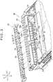
- FIG. 3 is an exploded perspective view of a frame 30 and a shield member 50.
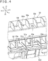
- FIG. 4 is an enlarged perspective view of a posterior wall portion 33 of the frame 30 on which the shield member 50 is mounted.
- FIG. 5 is an enlarged view of main parts shown in FIG. 2 .
- arrows X1 and X2 shown in FIG. 1 represent rightward and leftward directions, respectively; arrows Y1 and Y2 shown in FIG. 1 represent anterior and posterior directions, respectively; and arrows Z1 and Z2 shown in FIG. 1 represent superior and inferior directions, respectively.
- the electronic apparatus 1 is, for example, an entertainment apparatus that functions as a gaming machine or an audio-visual device.
- the electronic apparatus 1 outputs to a display device such as a television set moving image data generated through execution of a game program, image and audio data acquired from a recording medium such as an optical disc, and/or image and audio data acquired over a network.
- the electronic apparatus 1 is not limited to the entertainment apparatus such as the gaming machine, also may be a personal computer.
- the electronic apparatus 1 includes a circuit substrate 2.
- a plurality of integrated circuits 2a that function as, for example, a central processing unit (CPU), a graphics processing unit (GPU), and a memory are mounted on the circuit substrate 2.
- the electronic apparatus 1 further includes a cooling fan 21 that forms an air flow for cooling, for example, the integrated circuits 2a and components 41a that constitute a power circuit to be described later.
- the cooling fan 21 exemplarily rotates about an axis extending in a superior-inferior direction.
- the electronic apparatus 1 includes an optical disc drive 7.
- the optical disc drive 7 and the cooling fan 21 are exemplarily disposed at an anterior portion of the electronic apparatus 1.
- a power unit 40 that includes a power circuit is disposed posterior to the optical disc drive 7 and the cooling fan 21.
- the power circuit uses electricity received from an external power source to thereby supply the integrated circuits 2a, the cooling fan 21, and the optical disc drive 7 with drive power therefor.
- Layout of the cooling fan 21, the optical disc drive 7, and the power unit 40 in the electronic apparatus 1 is illustrative only and may be changed as appropriate.
- the electronic apparatus 1 includes an exterior member that constitutes an exterior of the electronic apparatus 1.
- the exterior member exemplarily includes the superior cover 3 that constitutes the superior surface of the electronic apparatus 1, an inferior cover 4 that constitutes an inferior surface of the electronic apparatus 1, and the frame 30 that surrounds components incorporated in the electronic apparatus 1.
- the frame 30 exemplarily surrounds, for example, the cooling fan 21, the power unit 40, and the optical disc drive 7 mentioned previously.
- the cooling fan 21, the power unit 40, the optical disc drive 7, and the circuit substrate 2 are mounted, for example, on the frame 30.
- the frame 30 includes a posterior wall portion 33, a right wall portion 34, a left wall portion 35, and an anterior wall portion 36 (see FIG.
- the posterior wall portion 33 is disposed posterior to the components incorporated in the electronic apparatus 1.
- the right wall portion 34 extends anteriorly from a right end of the posterior wall portion 33.
- the left wall portion 35 extends anteriorly from a left end of the posterior wall portion 33.
- the anterior wall portion 36 is formed between an anterior end of the right wall portion 34 and an anterior end of the left wall portion 35.
- the exterior member including the frame 30, the superior cover 3, and the inferior cover 4 is formed, for example, of a resin such as an acrylonitrile butadiene styrene (ABS) resin or a polycarbonate.
- ABS acrylonitrile butadiene styrene
- the electronic apparatus may include as the exterior member a box-shaped superior housing that is open inferiorly and a box-shaped inferior housing that is open superiorly and combined with the superior housing in the superior-inferior direction.
- the exterior member of the electronic apparatus may not include a frame.
- the posterior wall portion 33 of the frame 30 has an opening E1 formed therein for exhausting to the outside air that is exposed to heat generated by, for example, the integrated circuits 2a.
- a first air passage S1 is formed around the cooling fan 21.
- a wall portion 39 (see FIG. 1 ) that is arcuately curved to surround the cooling fan 21 is formed around the cooling fan 21.
- the first air passage S1 is defined between an outer periphery of the cooling fan 21 and the wall portion 39.
- the wall portion 39 is exemplarily formed integrally with the frame 30.
- the frame 30 includes a covering portion 31 that covers a superior side of the cooling fan 21.
- the covering portion 31 has an opening 31a disposed superior to the cooling fan 21.
- the covering portion 31 is exemplarily joined with an anterior portion of the right wall portion 34 of the frame 30, an anterior portion of the left wall portion 35 of the frame 30, and the anterior wall portion 36 of the frame 30, to thereby cover not only the cooling fan 21, but also the optical disc drive 7.
- the shape of the frame 30 in the electronic apparatus 1 is illustrative only and not limiting, and may be changed as appropriate.
- the electronic apparatus 1 includes a second air passage S2 to which the first air passage S1 leads.
- the second air passage S2 is exemplarily disposed posterior to the first air passage S1.
- the second air passage S2 is also covered in the covering portion 31 included in the frame 30.
- the frame 30 includes the right wall portion and the left wall portion that define the second air passage S2.
- the electronic apparatus 1 further includes a third air passage S3 to which the second air passage S2 leads.
- the third air passage S3 is exemplarily defined by a case 42 of the power unit 40.
- the case 42 is connected with the wall portions that define the second air passage S2 and with the covering portion 31.
- a circuit substrate 41 on which the components 41a that constitute the power circuit is mounted is disposed inside the case 42.
- the electronic apparatus 1 includes heat-generating components that are cooled by an air flow formed by the first to third air passages S1 to S3.
- the heat-generating components include, but are not limited to, the integrated circuits 2a, and the components 41a that constitute the power circuit (e.g., a transformer).
- the electronic apparatus 1 includes a heat sink 5 that is exemplarily disposed superior to the integrated circuits 2a.
- the heat sink 5 is exemplarily disposed in the second air passage S2.
- the third air passage S3 is defined by the case 42 of the power unit 40.
- the components 41a that constitute the power circuit are cooled by the air that passes through the third air passage S3.
- the components disposed in the first to third air passages S1 to S3 in the electronic apparatus 1 are illustrative only and not limiting, and may be changed as appropriate.
- the electronic apparatus 1 has the opening E1 formed at the most downstream portion of the first to third air passages S1 to S3.
- the opening E1 opens toward the posterior. Air in the first to third air passages S1 to S3 is exhausted to the outside through the opening E1.
- the opening E1 is formed exemplarily in the exterior member of the electronic apparatus 1. More specifically, as shown in FIG. 4 , the opening E1 is formed in the posterior wall portion 33 of the frame 30 as one component of the exterior member.
- the posterior wall portion 33 is disposed posterior to the case 42 that constitutes the third air passage S3.
- the case 42 of the power unit 40 opens to the posterior and the opening of the case 42 has an edge connected with the posterior wall portion 33.
- the opening E1 has a rectangular shape extending slenderly in a lateral direction.
- the posterior wall portion 33 of the frame 30 exemplarily includes an intermediate wall portion 33c and an inferior wall portion 33d.
- the intermediate wall portion 33c is disposed superior to the opening E1.
- the inferior wall portion 33d is disposed inferior to the opening E1.
- a plurality of partitions 33a are formed in juxtaposition with each other in the lateral direction between an inferior edge of the intermediate wall portion 33c and a superior edge of the inferior wall portion 33d.
- the inferior wall portion 33d has a plurality of openings 33k through which a plurality of connectors 2b (see FIG. 2 ) mounted on the circuit substrate 2 are individually exposed to the posterior.
- an air passage S4 is exemplarily defined superior to the intermediate wall portion 33c. The air passage S4 will be detailed later.
- the electronic apparatus 1 includes the shield member 50 that is mounted externally on a main unit of the electronic apparatus 1.
- the main unit of the electronic apparatus 1 includes, for example, the exterior member including the frame 30, the power unit 40, the cooling fan 21, and the first to third air passages S1 to S3 described previously.
- the shield member 50 is mounted, specifically, on the outside of a member having the opening E1.
- the shield member 50 is exemplarily mounted to the frame 30 that is one component of the exterior member.
- the shield member 50 is molded separately from the frame 30.
- the frame 30 corresponds to the "first member" in "WHAT IS CLAIMED IS" and the shield member 50 corresponds to the "second member” in "WHAT IS CLAIMED IS.”
- the shield member 50 is configured so as to prevent the inside of the electronic apparatus 1 when viewed from the posterior side of the electronic apparatus 1 from being exposed to the outside through the opening E1.
- the case 42 of the power unit 40 is disposed anterior to the posterior wall portion 33 in which the opening E1 is formed.
- the shield member 50 prevents the inside of the case 42, specifically, the components 41a (see FIG. 2 ) that constitute the power circuit from being exposed to the outside.
- the shield member 50 includes a shield wall portion 53 that is spaced posterior from the opening E1. Specifically, the shield wall portion 53 is spaced posterior from an inferior edge portion 33g of the intermediate wall portion 33c and a superior edge portion 33h of the inferior wall portion 33d.
- the inferior edge portion 33g and the superior edge portion 33h constitute the opening E1.
- the shield wall portion 53 is disposed inferior to the intermediate wall portion 33c and superior to the inferior wall portion 33d. Thereby, the shield wall portion 53 covers the opening E1.
- the foregoing arrangements enable the shield wall portion 53 to prevent the inside of the case 42 from being exposed when the electronic apparatus 1 is viewed from the posterior side.
- the shield wall portion 53 exemplarily has a width in a superior-inferior direction corresponding to a width in the superior-inferior direction of the opening E1.
- the shield wall portion 53 has a superior edge disposed on a straight line L1 that passes through the inferior edge portion 33g of the intermediate wall portion 33c.
- the shield wall portion 53 has a width in the lateral direction corresponding to a width in the lateral direction of the opening E1, specifically, a width in the lateral direction of the posterior wall portion 33. It is noted that the shield wall portion 53 may have the superior edge disposed superior to the straight line L1.
- the shield member 50 exemplarily includes a bottom portion 54 that extends anteriorly from an inferior edge of the shield wall portion 53.
- the bottom portion 54 has an anterior edge 54a (see FIG. 4 ) connected with the posterior wall portion 33 of the frame 30. More specifically, the anterior edge 54a of the bottom portion 54 is connected with the superior edge portion 33h of the inferior wall portion 33d of the posterior wall portion 33.
- the shield member 50 may not include the bottom portion 54.
- the shield member 50 includes a plurality of guide portions 51 and 52.
- the guide portions 51 and 52 are disposed in juxtaposition with each other in the lateral direction.
- the guide portions 51 and 52 guide air flows through the opening E1.
- the guide portions 51 and 52 are disposed in a direction in which air flows through the opening E1.
- the guide portions 51 and 52 are exemplarily disposed posterior to the opening E1, guiding the air that passes through the opening E1 so as to flow posteriorly.
- the guide portions 51 and 52 each extend in the anterior-posterior direction.
- the guide portions 51 and 52 may be inclined to the right or left.
- the guide portions 51 and 52 each have a plate shape.
- the guide portions 51 and 52 each have a width in the superior-inferior direction corresponding to a width in the superior-inferior direction of the opening E1.
- the guide portions 51 and 52 having configurations as described above, can prevent the inside of the case 42 from being visible when, for example, the posterior side of the electronic apparatus 1 is viewed from an obliquely right direction or from an obliquely left direction.
- the shield member 50 exemplarily includes a plurality of first guide portions 51 and a plurality of second guide portions 52.
- the first guide portions 51 each include engagement portions 51a and 51b.
- the engagement portions 51a and 51b are hooked onto the main unit of the electronic apparatus 1 so that the shield member 50 is not separated from the main unit.
- the engagement portions 51a and 51b are exemplarily hooked onto the exterior member of the electronic apparatus 1 so that the shield member 50 is not separated posteriorly from the exterior member. More specifically, the engagement portions 51a and 51b are hooked onto the posterior wall portion 33 of the frame 30.
- the foregoing structure allows the shield member 50 to be mounted to the electronic apparatus 1 without the need to use a screw or other fastener, or using a fewer number of fasteners. Appearance of the electronic apparatus 1 can thereby be improved. Additionally, the shield member 50 can have a central portion in the lateral direction mounted to the frame 30 using the first guide portions 51. As a result, the shield member 50 can be prevented from being deformed such that the central portion thereof is separated from the frame 30.
- the first guide portions 51 each extend anteriorly from the shield wall portion 53 and have a foremost part disposed inside the opening E1.
- the engagement portions 51a and 51b are formed at an anterior end of the first guide portion 51 and hooked at an edge of the opening E1.
- the first guide portion 51 exemplarily includes two engagement portions 51a and 51b formed at the anterior end thereof.
- a protrusion that protrudes superiorly is formed as a first engagement portion 51a at the anterior end of the first guide portion 51.
- the protrusion as the first engagement portion 51a is caught at an edge on a superior side of the opening E1, specifically, the inferior edge portion 33g of the intermediate wall portion 33c of the posterior wall portion 33.
- the protrusion as the first engagement portion 51a is caught at an anterior end of the inferior edge portion 33g.
- a protrusion that protrudes inferiorly is formed as a second engagement portion 51b at the anterior end of the first guide portion 51.
- the protrusion as the second engagement portion 51b is caught at an edge on an inferior side of the opening E1, specifically, the superior edge portion 33h of the inferior wall portion 33d of the posterior wall portion 33. More specifically, the protrusion as the second engagement portion 51b is caught at an anterior end of the superior edge portion 33h.
- the shield member 50 is mounted to the exterior member of the electronic apparatus 1, specifically, the frame 30 through the engagement portions 51a and 51b.
- the engagement portions 51a and 51b do not serve to block the air flow through the opening E1.
- screws or any other fasteners are not exemplarily used to mount the shield member 50 on the posterior wall portion 33 of the frame 30. Instead of the example illustrated in the electronic apparatus 1, however, screws or any other fasteners may be used to mount the shield member 50.
- the use of the first guide portions 51 allows the number of fasteners to be decreased. As a result, appearance of the electronic apparatus 1 can be improved.
- the first guide portions 51 each include a superior portion 51c and an inferior portion 51d that are spaced apart from each other in the superior-inferior direction.
- the first guide portions 51 each have a slit 51e formed therein to extend from an anterior end toward the posterior.
- the superior portion 51c is disposed superior to the slit 51e and the inferior portion 51d is disposed inferior to the slit 51e.
- the first engagement portion 51a is formed at an anterior end of the superior portion 51c.
- the second engagement portion 51b is formed at an anterior end of the inferior portion 51d.
- the shield member 50 includes the bottom portion 54.
- the inferior portion 51d of the first guide portion 51 has an inferior edge connected with the bottom portion 54.
- the inferior portion 51d has a foremost part extending anteriorly beyond the anterior edge 54a (see FIG. 4 ) of the bottom portion 54.
- the first guide portion 51 is elastically deformable such that the superior portion 51c and the inferior portion 51d can be brought close to each other in the superior-inferior direction.
- This structure facilitates mounting of the shield member 50 on the main unit of the electronic apparatus 1.
- elastically deforming the first guide portions 51 allows the shield member 50 to be mounted in the edge of the opening E1 in the frame 30.
- both the superior portion 51c and the inferior portion 51d are elastically deformable in the superior-inferior direction.
- the superior portion 51c is elastically deformable such that the first engagement portion 51a moves inferiorly
- the inferior portion 51d is elastically deformable such that the second engagement portion 51b moves superiorly.
- only either the superior portion 51c or the inferior portion 51d may be elastically deformable in the superior-inferior direction.
- the second engagement portion 51b of the inferior portion 51d has an inclined surface 51i.
- the inclined surface 51i extends inferiorly and posteriorly.
- the foregoing arrangement further facilitates the assembly work of the electronic apparatus 1.
- the first engagement portion 51a of the superior portion 51c is first caught by the edge of the opening E1 and the inclined surface 51i of the inferior portion 51d is thereafter brought into abutment with the edge of the opening E1.
- the foregoing procedure causes the inferior portion 51d to be elastically deformed superiorly to thereby move into the inside of the opening E1.
- the second engagement portion 51b is then caught by the edge of the opening E1, specifically, the anterior edge of the superior edge portion 33h of the inferior wall portion 33d.
- the first guide portions 51 engage with the frame 30 so as to prevent the shield member 50 from being deviated in the lateral direction with respect to the frame 30.
- recesses (grooves) 33e are exemplarily formed in the edge of the opening E1.
- the posterior wall portion 33 of the frame 30 has the recesses 33e formed in the superior edge portion 33h of the inferior wall portion 33d.
- the recesses 33e extend from an anterior edge to a posterior edge of the superior edge portion 33h.
- Inferior edges of the first guide portions 51 more specifically, inferior edges of the foremost parts of the inferior portions 51d are disposed in the respective recesses 33e. This arrangement can prevent the shield member 50 from being deviated in the lateral direction with respect to the frame 30.
- the posterior wall portion 33 of the frame 30 may have recesses formed in an inferior edge of the intermediate wall portion 33c.
- the recesses extend from an anterior edge to a posterior edge of the intermediate wall portion 33c.
- superior edges of the first guide portions 51 more specifically, superior edges of the superior portions 51c are disposed in the respective recesses in the intermediate wall portion 33c. This arrangement can also prevent the shield member 50 from being deviated in the lateral direction with respect to the frame 30.
- the shield member 50 includes the first guide portions 51 each being spaced apart from each other in the lateral direction. This arrangement can achieve mounting strength of the shield member 50 with respect to the frame 30.
- the shield member 50 further includes the second guide portions 52. As shown in FIG. 3 , unlike the first guide portions 51, the second guide portions 52 do not include the engagement portions that are to be caught by the frame 30.
- the second guide portions 52, and the first guide portions 51 are arranged in juxtaposition with each other in the lateral direction. Specifically, one or a plurality of second guide portions 52 are disposed between two adjacent first guide portions 51. This arrangement can facilitate the mounting work of the shield member 50.
- varying the ratio of the second guide portions 52 in a plurality of guide portions allows a force for mounting the shield member 50 to be adjusted.
- the force for mounting the shield member 50 can be reduced by increasing the ratio of the second guide portions 52 while decreasing the ratio of the first guide portions 51.
- one second guide portion 52 is formed between two adjacent first guide portions 51. As shown in FIG. 4 , the second guide portions 52 are disposed in tandem with the respective partitions 33a of the posterior wall portion 33 in the anterior-posterior direction. This arrangement can prevent the second guide portions 52 from resisting air flow. It is noted that the number of second guide portions 52 disposed between two adjacent first guide portions 51 in the example of the electronic apparatus 1 is illustrative only and not limiting and may be two or three.
- the electronic apparatus 1 includes the intermediate wall portion 33c that constitutes the edge of the opening E1.
- the intermediate wall portion 33c is exemplarily included in the posterior wall portion 33 of the frame 30.
- the shield wall portion 53 of the shield member 50 is spaced posteriorly from the intermediate wall portion 33c.
- an opening E2 that opens superiorly is formed between the inferior edge portion 33g of the intermediate wall portion 33c and the shield wall portion 53.
- Air in the third air passage S3 flows through the opening E2 between the intermediate wall portion 33c and the shield wall portion 53 to be exhausted to the outside.
- This structure can smoothly discharge the air, while preventing the inside of the main unit of the electronic apparatus 1, specifically, the inside of the case 42 of the power unit 40 from being exposed to the outside.
- widening a gap between the intermediate wall portion 33c and the shield wall portion 53 can enhance air exhaust efficiency without allowing the inside of the case 42 to be exposed.
- the intermediate wall portion 33c and the shield wall portion 53 are inclined. Specifically, the intermediate wall portion 33c and the shield wall portion 53 extend obliquely posteriorly and superiorly. The intermediate wall portion 33c and the shield wall portion 53 are disposed so as not to overlap each other in a plan view. Specifically, the shield wall portion 53 has an anterior end (inferior end) disposed posterior to a posterior end (superior end) of the intermediate wall portion 33c.
- the air passage S4 is exemplarily formed superior to the intermediate wall portion 33c.
- the exterior member of the electronic apparatus 1 includes a shield wall portion 3a that is disposed posterior to the superior edge of the intermediate wall portion 33c.
- the shield wall portion 3a can prevent the inside of the case 42 of the power unit 40 from being exposed to the outside through the air passage S4.
- the shield wall portion 3a is exemplarily molded integrally with the superior cover 3.
- the shield wall portion 3a is disposed superior to the intermediate wall portion 33c.
- An opening E3 that opens inferiorly is formed between an inferior edge of the shield wall portion 3a and the superior edge of the intermediate wall portion 33c.
- Air in the case 42 (specifically, the third air passage S3) flows through the opening E3 between the shield wall portion 3a of the superior cover 3 and the intermediate wall portion 33c and through the opening E2 between the intermediate wall portion 33c and the shield wall portion 53 of the shield member 50 to thereby be exhausted to the outside.
- the shield wall portion 3a of the superior cover 3 is exemplarily inclined as with the intermediate wall portion 33c of the frame 30 and the shield wall portion 53 of the shield member 50. Specifically, as shown in FIG. 5 , the shield wall portion 3a of the superior cover 3 extends obliquely posteriorly and superiorly in a cut plane taken in the anterior-posterior direction.
- the posterior wall portion 33 of the frame 30 exemplarily includes a superior wall portion 33m that is disposed superior to, and posterior to, the intermediate wall portion 33c.
- the superior wall portion 33m is disposed inside the shield wall portion 3a of the superior cover 3. Reference is made to FIG. 3 .
- the posterior wall portion 33 includes a plurality of guide portions 33p that are disposed in juxtaposition with each other in the lateral direction. The guide portions 33p extend anteriorly from the superior wall portion 33m and connect to the superior edge of the intermediate wall portion 33c.
- the electronic apparatus 1 includes the shield member 50.
- the shield member 50 includes the first and second guide portions 51 and 52 that are disposed in juxtaposition with each other in the lateral direction and that guide air passing through the opening E1 formed in the frame 30.
- the first guide portions 51 each include the engagement portions 51a and 51b that are hooked onto the posterior wall portion 33 of the frame 30.
- the shield member 50 is mounted to the frame 30 via the engagement portions 51a and 51b.
- the shield member 50 can be mounted to the electronic apparatus 1 without the need to use a screw or other fastener, or using a fewer number of fasteners. Appearance of the electronic apparatus 1 can thus be improved.
- the shield member 50 though including the multiple first guide portions 51, may include one first guide portion 51.
- the first guide portions 51 each have protrusions formed as the engagement portions 51a and 51b.
- the engagement portions 51a and 51b may, however, not necessarily be protrusions.
- the engagement portions 51a and 51b have a structure that allows the engagement portions 51a and 51b to be caught by the posterior wall portion 33 so as not to be separated posteriorly from the posterior wall portion 33 of the frame 30.
- the opening E1 may have protrusions formed at the edge thereof and the first guide portions 51 may have recesses formed therein as engagement portions, so that the protrusions can be caught in the recesses.
- the engagement portions 51a and 51b of the first guide portions 51 are exemplarily hooked onto the posterior wall portion 33 of the frame 30.
- the engagement portions 51a and 51b of the first guide portions 51 may nonetheless be hooked onto another member.
- the first guide portions 51 may extend anteriorly further ahead of the edge of the opening E1.
- the second engagement portions 51b formed at the anterior ends of the inferior ends of the first guide portions 51 may even be hooked onto a part covered in the frame 30, the superior cover 3, and the inferior cover 4, for example, the case 42 of the power unit 40.
- the case 42 may be used as the "first member" in "WHAT IS CLAIMED IS.”
- the shield member 50 may include a plurality of louvers in place of the shield wall portion 53.
- the louvers are disposed in juxtaposition with each other along the superior-inferior direction.
- the louvers are inclined such that the inside of the case 42 of the power unit 40 is not visible.
- the shield member 50 includes the first and second guide portions 51 and 52 that are disposed in juxtaposition with each other in the lateral direction along the louvers. The superior edges and the inferior edges of the first guide portions 51 may then have the anterior ends engaged with the exterior member of the electronic apparatus 1.
- the present disclosure contains subject matter related to that disclosed in Japanese Priority Patent Application JP 2016-152222 filed in the Japan Patent Office on August 2, 2016 .
Landscapes
- Engineering & Computer Science (AREA)
- Microelectronics & Electronic Packaging (AREA)
- Physics & Mathematics (AREA)
- Thermal Sciences (AREA)
- Multimedia (AREA)
- Cooling Or The Like Of Electrical Apparatus (AREA)
- Casings For Electric Apparatus (AREA)
Description
- The present disclosure relates to an electronic apparatus in which a heat generating part is cooled by air.
- Some electronic apparatuses such as gaming machines and personal computers have an opening for exhausting to the outside air that is exposed to heat generated by an integrated circuit mounted on a circuit substrate. The electronic apparatus disclosed in Japanese Patent Laid-Open No.
2014-239167 - Some design of the electronic apparatus makes it difficult to mold the guides integrally with the external member. Molding a member that includes a plurality of guides separately from the external member imposes a challenge on a structure for mounting the member including the guides to the external member. Using, for example, a screw or a similar fastener to mount the member including the guides to the external member may increase the number of assembly steps of the electronic apparatus or degrade aesthetic appearance of the electronic apparatus because of the faster being exposed to the outside. A large-sized opening may require that a plurality of fasteners be placed for mounting. The structure utilizing fasteners is thus particularly not preferable.
- It is desirable to provide an electronic apparatus that allows a member including a guide to be mounted to the electronic apparatus, while reducing an effect on appearance of the electronic apparatus.
- According to an embodiment of the present disclosure, there is provided an electronic apparatus including a first member and a second member. The first member has an opening through which air passes. The opening opens in a first direction. The second member is mounted to an outside of the first member. The second member includes a plurality of guide portions. The guide portions are disposed in juxtaposition with each other in a second direction that extends orthogonally to the first direction when viewed in the first direction. The guide portions guide air flowing through the opening. At least one guide portion out of the plurality of guide portions includes an engagement portion to be hooked onto the first member and the second member is mounted to the first member through the engagement portion. In accordance with the present disclosure, the member including a guide can be mounted to the electronic apparatus, while minimizing an effect on appearance of the electronic apparatus.
-
-
FIG. 1 is an exploded perspective view of an electronic apparatus according to an embodiment of the present disclosure; -
FIG. 2 is a cross-sectional view of the electronic apparatus, taken along line II-II inFIG. 1 ; -
FIG. 3 is an exploded perspective view of a frame and a shield member; -
FIG. 4 is an enlarged perspective view of a posterior wall portion of the frame on which the shield member is mounted; and -
FIG. 5 is an enlarged view of main parts shown inFIG. 2 . - An embodiment of the present disclosure will be described below.
FIG. 1 is an exploded perspective view of an electronic apparatus 1 according to an embodiment of the present disclosure.FIG. 1 shows the electronic apparatus 1 from which asuperior cover 3 constituting a superior surface has been removed.FIG. 2 is a cross-sectional view of the electronic apparatus 1, taken along line II-II inFIG. 1 .FIG. 3 is an exploded perspective view of aframe 30 and ashield member 50.FIG. 4 is an enlarged perspective view of aposterior wall portion 33 of theframe 30 on which theshield member 50 is mounted.FIG. 5 is an enlarged view of main parts shown inFIG. 2 . - Directional expressions as used herein are here defined as follows with reference to the electronic apparatus 1 viewed from the right-hand side in
FIG. 1 . Specifically, arrows X1 and X2 shown inFIG. 1 represent rightward and leftward directions, respectively; arrows Y1 and Y2 shown inFIG. 1 represent anterior and posterior directions, respectively; and arrows Z1 and Z2 shown inFIG. 1 represent superior and inferior directions, respectively. - The electronic apparatus 1 is, for example, an entertainment apparatus that functions as a gaming machine or an audio-visual device. The electronic apparatus 1 outputs to a display device such as a television set moving image data generated through execution of a game program, image and audio data acquired from a recording medium such as an optical disc, and/or image and audio data acquired over a network. The electronic apparatus 1 is not limited to the entertainment apparatus such as the gaming machine, also may be a personal computer.
- Reference is made to
FIG. 2 . The electronic apparatus 1 includes acircuit substrate 2. A plurality ofintegrated circuits 2a that function as, for example, a central processing unit (CPU), a graphics processing unit (GPU), and a memory are mounted on thecircuit substrate 2. The electronic apparatus 1 further includes acooling fan 21 that forms an air flow for cooling, for example, the integratedcircuits 2a andcomponents 41a that constitute a power circuit to be described later. In the electronic apparatus 1, thecooling fan 21 exemplarily rotates about an axis extending in a superior-inferior direction. - As shown in
FIG. 1 , the electronic apparatus 1 includes an optical disc drive 7. In the electronic apparatus 1, the optical disc drive 7 and thecooling fan 21 are exemplarily disposed at an anterior portion of the electronic apparatus 1. Apower unit 40 that includes a power circuit is disposed posterior to the optical disc drive 7 and thecooling fan 21. The power circuit uses electricity received from an external power source to thereby supply the integratedcircuits 2a, thecooling fan 21, and the optical disc drive 7 with drive power therefor. Layout of thecooling fan 21, the optical disc drive 7, and thepower unit 40 in the electronic apparatus 1 is illustrative only and may be changed as appropriate. - The electronic apparatus 1 includes an exterior member that constitutes an exterior of the electronic apparatus 1. As shown in
FIG. 1 , in the electronic apparatus 1, the exterior member exemplarily includes thesuperior cover 3 that constitutes the superior surface of the electronic apparatus 1, aninferior cover 4 that constitutes an inferior surface of the electronic apparatus 1, and theframe 30 that surrounds components incorporated in the electronic apparatus 1. In the electronic apparatus 1, theframe 30 exemplarily surrounds, for example, thecooling fan 21, thepower unit 40, and the optical disc drive 7 mentioned previously. Thecooling fan 21, thepower unit 40, the optical disc drive 7, and thecircuit substrate 2 are mounted, for example, on theframe 30. Reference is made toFIG. 3 . Theframe 30 includes aposterior wall portion 33, aright wall portion 34, aleft wall portion 35, and an anterior wall portion 36 (seeFIG. 1 ). Specifically, theposterior wall portion 33 is disposed posterior to the components incorporated in the electronic apparatus 1. Theright wall portion 34 extends anteriorly from a right end of theposterior wall portion 33. Theleft wall portion 35 extends anteriorly from a left end of theposterior wall portion 33. Theanterior wall portion 36 is formed between an anterior end of theright wall portion 34 and an anterior end of theleft wall portion 35. The exterior member including theframe 30, thesuperior cover 3, and theinferior cover 4 is formed, for example, of a resin such as an acrylonitrile butadiene styrene (ABS) resin or a polycarbonate. The components of the exterior member in the electronic apparatus 1 are illustrative only and not limiting. For example, the electronic apparatus may include as the exterior member a box-shaped superior housing that is open inferiorly and a box-shaped inferior housing that is open superiorly and combined with the superior housing in the superior-inferior direction. Specifically, the exterior member of the electronic apparatus may not include a frame. As will be later detailed, theposterior wall portion 33 of theframe 30 has an opening E1 formed therein for exhausting to the outside air that is exposed to heat generated by, for example, theintegrated circuits 2a. - Reference is made to
FIG. 2 . Air passages S1 to S3 that extend from the coolingfan 21 to the opening E1 (seeFIG. 5 ) are defined inside the electronic apparatus 1. A first air passage S1 is formed around the coolingfan 21. A wall portion 39 (seeFIG. 1 ) that is arcuately curved to surround the coolingfan 21 is formed around the coolingfan 21. The first air passage S1 is defined between an outer periphery of the coolingfan 21 and thewall portion 39. In the electronic apparatus 1, thewall portion 39 is exemplarily formed integrally with theframe 30. Theframe 30 includes a coveringportion 31 that covers a superior side of the coolingfan 21. The coveringportion 31 has anopening 31a disposed superior to the coolingfan 21. When the coolingfan 21 is driven, air is introduced into the coolingfan 21 through theopening 31a. As the coolingfan 21 is driven, the air flows to the first air passage S1 and further toward the posterior through the first air passage S1. In the electronic apparatus 1, the coveringportion 31 is exemplarily joined with an anterior portion of theright wall portion 34 of theframe 30, an anterior portion of theleft wall portion 35 of theframe 30, and theanterior wall portion 36 of theframe 30, to thereby cover not only the coolingfan 21, but also the optical disc drive 7. The shape of theframe 30 in the electronic apparatus 1 is illustrative only and not limiting, and may be changed as appropriate. - Reference is made to
FIG. 2 . The electronic apparatus 1 includes a second air passage S2 to which the first air passage S1 leads. In the electronic apparatus 1, the second air passage S2 is exemplarily disposed posterior to the first air passage S1. The second air passage S2 is also covered in the coveringportion 31 included in theframe 30. In addition, theframe 30 includes the right wall portion and the left wall portion that define the second air passage S2. - Reference is made to
FIG. 2 . The electronic apparatus 1 further includes a third air passage S3 to which the second air passage S2 leads. In the electronic apparatus 1, the third air passage S3 is exemplarily defined by acase 42 of thepower unit 40. Thecase 42 is connected with the wall portions that define the second air passage S2 and with the coveringportion 31. Acircuit substrate 41 on which thecomponents 41a that constitute the power circuit is mounted is disposed inside thecase 42. - The electronic apparatus 1 includes heat-generating components that are cooled by an air flow formed by the first to third air passages S1 to S3. Examples of the heat-generating components include, but are not limited to, the
integrated circuits 2a, and thecomponents 41a that constitute the power circuit (e.g., a transformer). As shown inFIG. 2 , the electronic apparatus 1 includes aheat sink 5 that is exemplarily disposed superior to theintegrated circuits 2a. Theheat sink 5 is exemplarily disposed in the second air passage S2. Additionally, as described above, the third air passage S3 is defined by thecase 42 of thepower unit 40. Thecomponents 41a that constitute the power circuit are cooled by the air that passes through the third air passage S3. The components disposed in the first to third air passages S1 to S3 in the electronic apparatus 1 are illustrative only and not limiting, and may be changed as appropriate. - Reference is made to
FIG. 5 . The electronic apparatus 1 has the opening E1 formed at the most downstream portion of the first to third air passages S1 to S3. The opening E1 opens toward the posterior. Air in the first to third air passages S1 to S3 is exhausted to the outside through the opening E1. In the electronic apparatus 1, the opening E1 is formed exemplarily in the exterior member of the electronic apparatus 1. More specifically, as shown inFIG. 4 , the opening E1 is formed in theposterior wall portion 33 of theframe 30 as one component of the exterior member. Theposterior wall portion 33 is disposed posterior to thecase 42 that constitutes the third air passage S3. Thecase 42 of thepower unit 40 opens to the posterior and the opening of thecase 42 has an edge connected with theposterior wall portion 33. In the electronic apparatus 1, the opening E1 has a rectangular shape extending slenderly in a lateral direction. - Reference is made to
FIG. 3 . In the electronic apparatus 1, theposterior wall portion 33 of theframe 30 exemplarily includes anintermediate wall portion 33c and aninferior wall portion 33d. Theintermediate wall portion 33c is disposed superior to the opening E1. Theinferior wall portion 33d is disposed inferior to the opening E1. A plurality ofpartitions 33a are formed in juxtaposition with each other in the lateral direction between an inferior edge of theintermediate wall portion 33c and a superior edge of theinferior wall portion 33d. Theinferior wall portion 33d has a plurality ofopenings 33k through which a plurality ofconnectors 2b (seeFIG. 2 ) mounted on thecircuit substrate 2 are individually exposed to the posterior. As shown inFIG. 5 , in the electronic apparatus 1, an air passage S4 is exemplarily defined superior to theintermediate wall portion 33c. The air passage S4 will be detailed later. - Reference is made to
FIG. 3 . The electronic apparatus 1 includes theshield member 50 that is mounted externally on a main unit of the electronic apparatus 1. The main unit of the electronic apparatus 1 includes, for example, the exterior member including theframe 30, thepower unit 40, the coolingfan 21, and the first to third air passages S1 to S3 described previously. Theshield member 50 is mounted, specifically, on the outside of a member having the opening E1. In the electronic apparatus 1, theshield member 50 is exemplarily mounted to theframe 30 that is one component of the exterior member. Theshield member 50 is molded separately from theframe 30. In the example of the electronic apparatus 1, theframe 30 corresponds to the "first member" in "WHAT IS CLAIMED IS" and theshield member 50 corresponds to the "second member" in "WHAT IS CLAIMED IS." - Reference is made to
FIG. 5 . Theshield member 50 is configured so as to prevent the inside of the electronic apparatus 1 when viewed from the posterior side of the electronic apparatus 1 from being exposed to the outside through the opening E1. In the electronic apparatus 1, thecase 42 of thepower unit 40 is disposed anterior to theposterior wall portion 33 in which the opening E1 is formed. Theshield member 50 prevents the inside of thecase 42, specifically, thecomponents 41a (seeFIG. 2 ) that constitute the power circuit from being exposed to the outside. Theshield member 50 includes ashield wall portion 53 that is spaced posterior from the opening E1. Specifically, theshield wall portion 53 is spaced posterior from aninferior edge portion 33g of theintermediate wall portion 33c and asuperior edge portion 33h of theinferior wall portion 33d. Theinferior edge portion 33g and thesuperior edge portion 33h constitute the opening E1. In addition, theshield wall portion 53 is disposed inferior to theintermediate wall portion 33c and superior to theinferior wall portion 33d. Thereby, theshield wall portion 53 covers the opening E1. The foregoing arrangements enable theshield wall portion 53 to prevent the inside of thecase 42 from being exposed when the electronic apparatus 1 is viewed from the posterior side. In the electronic apparatus 1, theshield wall portion 53 exemplarily has a width in a superior-inferior direction corresponding to a width in the superior-inferior direction of the opening E1. Theshield wall portion 53 has a superior edge disposed on a straight line L1 that passes through theinferior edge portion 33g of theintermediate wall portion 33c. In addition, theshield wall portion 53 has a width in the lateral direction corresponding to a width in the lateral direction of the opening E1, specifically, a width in the lateral direction of theposterior wall portion 33. It is noted that theshield wall portion 53 may have the superior edge disposed superior to the straight line L1. - Reference is made to
FIG. 5 . In the electronic apparatus 1, theshield member 50 exemplarily includes abottom portion 54 that extends anteriorly from an inferior edge of theshield wall portion 53. Thebottom portion 54 has ananterior edge 54a (seeFIG. 4 ) connected with theposterior wall portion 33 of theframe 30. More specifically, theanterior edge 54a of thebottom portion 54 is connected with thesuperior edge portion 33h of theinferior wall portion 33d of theposterior wall portion 33. Theshield member 50 may not include thebottom portion 54. - Reference is made to
FIG. 3 . Theshield member 50 includes a plurality ofguide portions guide portions guide portions guide portions guide portions guide portions guide portions - The
guide portions guide portions guide portions case 42 from being visible when, for example, the posterior side of the electronic apparatus 1 is viewed from an obliquely right direction or from an obliquely left direction. - In the electronic apparatus 1, the
shield member 50 exemplarily includes a plurality offirst guide portions 51 and a plurality ofsecond guide portions 52. As shown inFIG. 5 , thefirst guide portions 51 each includeengagement portions engagement portions shield member 50 is not separated from the main unit. In the electronic apparatus 1, theengagement portions shield member 50 is not separated posteriorly from the exterior member. More specifically, theengagement portions posterior wall portion 33 of theframe 30. The foregoing structure allows theshield member 50 to be mounted to the electronic apparatus 1 without the need to use a screw or other fastener, or using a fewer number of fasteners. Appearance of the electronic apparatus 1 can thereby be improved. Additionally, theshield member 50 can have a central portion in the lateral direction mounted to theframe 30 using thefirst guide portions 51. As a result, theshield member 50 can be prevented from being deformed such that the central portion thereof is separated from theframe 30. - Reference is made to
FIG. 5 . Thefirst guide portions 51 each extend anteriorly from theshield wall portion 53 and have a foremost part disposed inside the opening E1. Theengagement portions first guide portion 51 and hooked at an edge of the opening E1. In the electronic apparatus 1, thefirst guide portion 51 exemplarily includes twoengagement portions first engagement portion 51a at the anterior end of thefirst guide portion 51. The protrusion as thefirst engagement portion 51a is caught at an edge on a superior side of the opening E1, specifically, theinferior edge portion 33g of theintermediate wall portion 33c of theposterior wall portion 33. More specifically, the protrusion as thefirst engagement portion 51a is caught at an anterior end of theinferior edge portion 33g. Additionally, a protrusion that protrudes inferiorly is formed as asecond engagement portion 51b at the anterior end of thefirst guide portion 51. The protrusion as thesecond engagement portion 51b is caught at an edge on an inferior side of the opening E1, specifically, thesuperior edge portion 33h of theinferior wall portion 33d of theposterior wall portion 33. More specifically, the protrusion as thesecond engagement portion 51b is caught at an anterior end of thesuperior edge portion 33h. - The
shield member 50 is mounted to the exterior member of the electronic apparatus 1, specifically, theframe 30 through theengagement portions engagement portions shield member 50 on theposterior wall portion 33 of theframe 30. Instead of the example illustrated in the electronic apparatus 1, however, screws or any other fasteners may be used to mount theshield member 50. In this case, too, the use of thefirst guide portions 51 allows the number of fasteners to be decreased. As a result, appearance of the electronic apparatus 1 can be improved. - Reference is made to
FIG. 5 . Thefirst guide portions 51 each include asuperior portion 51c and aninferior portion 51d that are spaced apart from each other in the superior-inferior direction. Thefirst guide portions 51 each have aslit 51e formed therein to extend from an anterior end toward the posterior. Thesuperior portion 51c is disposed superior to theslit 51e and theinferior portion 51d is disposed inferior to theslit 51e. Thefirst engagement portion 51a is formed at an anterior end of thesuperior portion 51c. Thesecond engagement portion 51b is formed at an anterior end of theinferior portion 51d. As described previously, theshield member 50 includes thebottom portion 54. Theinferior portion 51d of thefirst guide portion 51 has an inferior edge connected with thebottom portion 54. Theinferior portion 51d has a foremost part extending anteriorly beyond theanterior edge 54a (seeFIG. 4 ) of thebottom portion 54. - The
first guide portion 51 is elastically deformable such that thesuperior portion 51c and theinferior portion 51d can be brought close to each other in the superior-inferior direction. This structure facilitates mounting of theshield member 50 on the main unit of the electronic apparatus 1. Specifically, in the assembly work of the electronic apparatus 1, elastically deforming thefirst guide portions 51 allows theshield member 50 to be mounted in the edge of the opening E1 in theframe 30. In one example of the electronic apparatus 1, both thesuperior portion 51c and theinferior portion 51d are elastically deformable in the superior-inferior direction. Specifically, thesuperior portion 51c is elastically deformable such that thefirst engagement portion 51a moves inferiorly and theinferior portion 51d is elastically deformable such that thesecond engagement portion 51b moves superiorly. In another example of the electronic apparatus 1, only either thesuperior portion 51c or theinferior portion 51d may be elastically deformable in the superior-inferior direction. - Reference is made to
FIG. 4 . Thesecond engagement portion 51b of theinferior portion 51d has an inclined surface 51i. The inclined surface 51i extends inferiorly and posteriorly. The foregoing arrangement further facilitates the assembly work of the electronic apparatus 1. For example, thefirst engagement portion 51a of thesuperior portion 51c is first caught by the edge of the opening E1 and the inclined surface 51i of theinferior portion 51d is thereafter brought into abutment with the edge of the opening E1. The foregoing procedure causes theinferior portion 51d to be elastically deformed superiorly to thereby move into the inside of the opening E1. Thesecond engagement portion 51b is then caught by the edge of the opening E1, specifically, the anterior edge of thesuperior edge portion 33h of theinferior wall portion 33d. - The
first guide portions 51 engage with theframe 30 so as to prevent theshield member 50 from being deviated in the lateral direction with respect to theframe 30. As shown inFIG. 3 , in the electronic apparatus 1, recesses (grooves) 33e are exemplarily formed in the edge of the opening E1. To state the foregoing differently, theposterior wall portion 33 of theframe 30 has therecesses 33e formed in thesuperior edge portion 33h of theinferior wall portion 33d. Therecesses 33e extend from an anterior edge to a posterior edge of thesuperior edge portion 33h. Inferior edges of thefirst guide portions 51, more specifically, inferior edges of the foremost parts of theinferior portions 51d are disposed in therespective recesses 33e. This arrangement can prevent theshield member 50 from being deviated in the lateral direction with respect to theframe 30. - The structure that prevents the
shield member 50 from being deviated in the lateral direction in the example of the electronic apparatus 1 is illustrative only and not limiting. For example, theposterior wall portion 33 of theframe 30 may have recesses formed in an inferior edge of theintermediate wall portion 33c. The recesses extend from an anterior edge to a posterior edge of theintermediate wall portion 33c. In this case, superior edges of thefirst guide portions 51, more specifically, superior edges of thesuperior portions 51c are disposed in the respective recesses in theintermediate wall portion 33c. This arrangement can also prevent theshield member 50 from being deviated in the lateral direction with respect to theframe 30. - As described above, the
shield member 50 includes thefirst guide portions 51 each being spaced apart from each other in the lateral direction. This arrangement can achieve mounting strength of theshield member 50 with respect to theframe 30. Theshield member 50 further includes thesecond guide portions 52. As shown inFIG. 3 , unlike thefirst guide portions 51, thesecond guide portions 52 do not include the engagement portions that are to be caught by theframe 30. Thesecond guide portions 52, and thefirst guide portions 51, are arranged in juxtaposition with each other in the lateral direction. Specifically, one or a plurality ofsecond guide portions 52 are disposed between two adjacentfirst guide portions 51. This arrangement can facilitate the mounting work of theshield member 50. Specifically, varying the ratio of thesecond guide portions 52 in a plurality of guide portions allows a force for mounting theshield member 50 to be adjusted. For example, the force for mounting theshield member 50 can be reduced by increasing the ratio of thesecond guide portions 52 while decreasing the ratio of thefirst guide portions 51. - In the electronic apparatus 1, one
second guide portion 52 is formed between two adjacentfirst guide portions 51. As shown inFIG. 4 , thesecond guide portions 52 are disposed in tandem with therespective partitions 33a of theposterior wall portion 33 in the anterior-posterior direction. This arrangement can prevent thesecond guide portions 52 from resisting air flow. It is noted that the number ofsecond guide portions 52 disposed between two adjacentfirst guide portions 51 in the example of the electronic apparatus 1 is illustrative only and not limiting and may be two or three. - As described above, the electronic apparatus 1 includes the
intermediate wall portion 33c that constitutes the edge of the opening E1. In the electronic apparatus 1, theintermediate wall portion 33c is exemplarily included in theposterior wall portion 33 of theframe 30. As shown inFIG. 5 , theshield wall portion 53 of theshield member 50 is spaced posteriorly from theintermediate wall portion 33c. Thus, an opening E2 that opens superiorly is formed between theinferior edge portion 33g of theintermediate wall portion 33c and theshield wall portion 53. Air in the third air passage S3 flows through the opening E2 between theintermediate wall portion 33c and theshield wall portion 53 to be exhausted to the outside. This structure can smoothly discharge the air, while preventing the inside of the main unit of the electronic apparatus 1, specifically, the inside of thecase 42 of thepower unit 40 from being exposed to the outside. For example, widening a gap between theintermediate wall portion 33c and theshield wall portion 53 can enhance air exhaust efficiency without allowing the inside of thecase 42 to be exposed. - Reference is made to
FIG. 5 . In the electronic apparatus 1, theintermediate wall portion 33c and theshield wall portion 53 are inclined. Specifically, theintermediate wall portion 33c and theshield wall portion 53 extend obliquely posteriorly and superiorly. Theintermediate wall portion 33c and theshield wall portion 53 are disposed so as not to overlap each other in a plan view. Specifically, theshield wall portion 53 has an anterior end (inferior end) disposed posterior to a posterior end (superior end) of theintermediate wall portion 33c. - Reference is made to
FIG. 5 . In the electronic apparatus 1, the air passage S4 is exemplarily formed superior to theintermediate wall portion 33c. The exterior member of the electronic apparatus 1 includes ashield wall portion 3a that is disposed posterior to the superior edge of theintermediate wall portion 33c. Theshield wall portion 3a can prevent the inside of thecase 42 of thepower unit 40 from being exposed to the outside through the air passage S4. In the electronic apparatus 1, theshield wall portion 3a is exemplarily molded integrally with thesuperior cover 3. Theshield wall portion 3a is disposed superior to theintermediate wall portion 33c. An opening E3 that opens inferiorly is formed between an inferior edge of theshield wall portion 3a and the superior edge of theintermediate wall portion 33c. Air in the case 42 (specifically, the third air passage S3) flows through the opening E3 between theshield wall portion 3a of thesuperior cover 3 and theintermediate wall portion 33c and through the opening E2 between theintermediate wall portion 33c and theshield wall portion 53 of theshield member 50 to thereby be exhausted to the outside. - In the electronic apparatus 1, the
shield wall portion 3a of thesuperior cover 3 is exemplarily inclined as with theintermediate wall portion 33c of theframe 30 and theshield wall portion 53 of theshield member 50. Specifically, as shown inFIG. 5 , theshield wall portion 3a of thesuperior cover 3 extends obliquely posteriorly and superiorly in a cut plane taken in the anterior-posterior direction. - Additionally, in the electronic apparatus 1, the
posterior wall portion 33 of theframe 30 exemplarily includes asuperior wall portion 33m that is disposed superior to, and posterior to, theintermediate wall portion 33c. Thesuperior wall portion 33m is disposed inside theshield wall portion 3a of thesuperior cover 3. Reference is made toFIG. 3 . Theposterior wall portion 33 includes a plurality ofguide portions 33p that are disposed in juxtaposition with each other in the lateral direction. Theguide portions 33p extend anteriorly from thesuperior wall portion 33m and connect to the superior edge of theintermediate wall portion 33c. - As described above, the electronic apparatus 1 includes the
shield member 50. Theshield member 50 includes the first andsecond guide portions frame 30. Of the first andsecond guide portions first guide portions 51 each include theengagement portions posterior wall portion 33 of theframe 30. Theshield member 50 is mounted to theframe 30 via theengagement portions shield member 50 can be mounted to the electronic apparatus 1 without the need to use a screw or other fastener, or using a fewer number of fasteners. Appearance of the electronic apparatus 1 can thus be improved. - It should be noted that the present disclosure is not limited to the electronic apparatus 1 according to the above-described embodiment and may include various modifications.
- For example, the
shield member 50, though including the multiplefirst guide portions 51, may include onefirst guide portion 51. - The
first guide portions 51 each have protrusions formed as theengagement portions engagement portions engagement portions engagement portions posterior wall portion 33 so as not to be separated posteriorly from theposterior wall portion 33 of theframe 30. For example, the opening E1 may have protrusions formed at the edge thereof and thefirst guide portions 51 may have recesses formed therein as engagement portions, so that the protrusions can be caught in the recesses. - In the electronic apparatus 1, the
engagement portions first guide portions 51 are exemplarily hooked onto theposterior wall portion 33 of theframe 30. Theengagement portions first guide portions 51 may nonetheless be hooked onto another member. For example, thefirst guide portions 51 may extend anteriorly further ahead of the edge of the opening E1. Thesecond engagement portions 51b formed at the anterior ends of the inferior ends of thefirst guide portions 51 may even be hooked onto a part covered in theframe 30, thesuperior cover 3, and theinferior cover 4, for example, thecase 42 of thepower unit 40. Specifically, thecase 42 may be used as the "first member" in "WHAT IS CLAIMED IS." - Additionally, the
shield member 50 may include a plurality of louvers in place of theshield wall portion 53. The louvers are disposed in juxtaposition with each other along the superior-inferior direction. Preferably, the louvers are inclined such that the inside of thecase 42 of thepower unit 40 is not visible. In this case, theshield member 50 includes the first andsecond guide portions first guide portions 51 may then have the anterior ends engaged with the exterior member of the electronic apparatus 1. - The present disclosure contains subject matter related to that disclosed in Japanese Priority Patent Application JP
2016-152222 filed in the Japan Patent Office on August 2, 2016 - It should be understood by those skilled in the art that various modifications, combinations, sub-combinations and alterations may occur depending on design requirements and other factors insofar as they are within the scope of the appended claims or the equivalents thereof.
Claims (8)
- An electronic apparatus comprising:a first member having an opening through which air passes, the opening opening in a first direction; anda second member mounted to an outside of the first member, the second member including a plurality of guide portions disposed in juxtaposition with each other in a second direction that extends orthogonally to the first direction when viewed in the first direction, the guide portions guiding air flowing through the opening,at least one guide portion out of the plurality of guide portions including an engagement portion to be hooked onto the first member,the second member being mounted to the first member through the engagement portion.
- The electronic apparatus according to claim 1, wherein
the at least one guide portion extends into an inside of the opening and is hooked onto an edge of the opening by the engagement portion. - The electronic apparatus according to claim 1, wherein
the guide portions include, as the at least one guide portion, a plurality of first guide portions disposed to be spaced apart from each other in the second direction. - The electronic apparatus according to claim 3, wherein
the guide portions include second guide portions that do not include the engagement portions, and
the second guide portions, and the first guide portions, are disposed in juxtaposition with each other in the second direction. - The electronic apparatus according to claim 1, wherein
the at least one guide portion is elastically deformable so that the engagement portion is movable in a third direction that is orthogonal to both the first direction and the second direction. - The electronic apparatus according to claim 5, wherein
the at least one guide portion includes a first portion and a second portion that are spaced apart from each other in the third direction,
the first portion and the second portion each include the engagement portion, and
the at least one guide portion is elastically deformable so that the first portion and the second portion can be brought close to each other in the third direction. - The electronic apparatus according to claim 1, wherein
the second member includes a shield wall portion that is spaced away in the first direction from an edge of the opening in the first member and that covers the opening, and
the guide portions extend from the shield wall portion toward the opening. - The electronic apparatus according to claim 1, wherein
the at least one guide portion engages with the first member so as to prevent the second member from being deviated in the second direction with respect to the first member of the electronic apparatus.
Applications Claiming Priority (1)
| Application Number | Priority Date | Filing Date | Title |
|---|---|---|---|
| JP2016152222A JP6502900B2 (en) | 2016-08-02 | 2016-08-02 | Electronics |
Publications (2)
| Publication Number | Publication Date |
|---|---|
| EP3280234A1 true EP3280234A1 (en) | 2018-02-07 |
| EP3280234B1 EP3280234B1 (en) | 2019-04-17 |
Family
ID=59676954
Family Applications (1)
| Application Number | Title | Priority Date | Filing Date |
|---|---|---|---|
| EP17183764.4A Active EP3280234B1 (en) | 2016-08-02 | 2017-07-28 | Electronic apparatus |
Country Status (4)
| Country | Link |
|---|---|
| US (1) | US10278303B2 (en) |
| EP (1) | EP3280234B1 (en) |
| JP (1) | JP6502900B2 (en) |
| CN (1) | CN107683065B (en) |
Families Citing this family (4)
| Publication number | Priority date | Publication date | Assignee | Title |
|---|---|---|---|---|
| US10034411B2 (en) * | 2015-09-25 | 2018-07-24 | Apple Inc. | Thermal flow assembly including integrated fan |
| US10555441B2 (en) * | 2018-01-26 | 2020-02-04 | Super Micro Computer Inc. | Winds shroud and server using the same |
| US11089712B2 (en) * | 2019-03-19 | 2021-08-10 | Microsoft Technology Licensing, Llc | Ventilated shield can |
| US20240422936A1 (en) * | 2023-06-16 | 2024-12-19 | Plume Design, Inc. | Exhaust airflow direction control |
Citations (5)
| Publication number | Priority date | Publication date | Assignee | Title |
|---|---|---|---|---|
| WO2008001396A1 (en) * | 2006-06-28 | 2008-01-03 | Gianus S.P.A. | Filter-holder case |
| US20080121107A1 (en) * | 2006-10-12 | 2008-05-29 | Andreas Pfannenberg | Device for the passage of air with control unit |
| US20110005177A1 (en) * | 2006-10-06 | 2011-01-13 | Andreas Pfannenberg | Filter fan |
| US20130067875A1 (en) * | 2010-04-19 | 2013-03-21 | Rittal Gmbh & Co. Kg | Filter unit for a switchgear cabinet |
| US20140362529A1 (en) * | 2013-06-07 | 2014-12-11 | Sony Computer Entertainment Inc. | Electronic apparatus |
Family Cites Families (10)
| Publication number | Priority date | Publication date | Assignee | Title |
|---|---|---|---|---|
| JPH0755774Y2 (en) * | 1988-05-26 | 1995-12-20 | 富士通株式会社 | Switch protective cover mounting structure |
| US6362958B1 (en) * | 2000-08-11 | 2002-03-26 | Ming-Chuan Yu | Detachable cooling device for computer |
| JP2005091674A (en) * | 2003-09-17 | 2005-04-07 | Ricoh Co Ltd | Exterior cover member, exhaust device, and image forming apparatus |
| TWI300327B (en) * | 2006-02-10 | 2008-08-21 | Benq Corp | Electronic device and heat dissipation module thereof |
| CN200969238Y (en) * | 2006-10-08 | 2007-10-31 | 淞耀企业股份有限公司 | Structural Improvement of Heat Dissipation Guide Fin Group |
| JP2013059138A (en) * | 2011-09-07 | 2013-03-28 | Sumitomo Wiring Syst Ltd | Assembly including lock mechanism |
| JP6030327B2 (en) * | 2012-04-18 | 2016-11-24 | 篠原電機株式会社 | Electrical equipment box ventilation equipment |
| JP5838946B2 (en) * | 2012-10-15 | 2016-01-06 | 住友電装株式会社 | Combined operation device |
| CN204104277U (en) * | 2014-07-30 | 2015-01-14 | 沪华五金电子(吴江)有限公司 | A kind of outdoor cabinet |
| DE102015101304B3 (en) * | 2015-01-29 | 2016-03-17 | Fujitsu Technology Solutions Intellectual Property Gmbh | Rack server for a server rack |
-
2016
- 2016-08-02 JP JP2016152222A patent/JP6502900B2/en active Active
-
2017
- 2017-07-27 US US15/661,203 patent/US10278303B2/en active Active
- 2017-07-28 CN CN201710635953.9A patent/CN107683065B/en active Active
- 2017-07-28 EP EP17183764.4A patent/EP3280234B1/en active Active
Patent Citations (6)
| Publication number | Priority date | Publication date | Assignee | Title |
|---|---|---|---|---|
| WO2008001396A1 (en) * | 2006-06-28 | 2008-01-03 | Gianus S.P.A. | Filter-holder case |
| US20110005177A1 (en) * | 2006-10-06 | 2011-01-13 | Andreas Pfannenberg | Filter fan |
| US20080121107A1 (en) * | 2006-10-12 | 2008-05-29 | Andreas Pfannenberg | Device for the passage of air with control unit |
| US20130067875A1 (en) * | 2010-04-19 | 2013-03-21 | Rittal Gmbh & Co. Kg | Filter unit for a switchgear cabinet |
| US20140362529A1 (en) * | 2013-06-07 | 2014-12-11 | Sony Computer Entertainment Inc. | Electronic apparatus |
| JP2014239167A (en) | 2013-06-07 | 2014-12-18 | 株式会社ソニー・コンピュータエンタテインメント | Electronic apparatus |
Also Published As
| Publication number | Publication date |
|---|---|
| EP3280234B1 (en) | 2019-04-17 |
| JP2018022751A (en) | 2018-02-08 |
| US20180042135A1 (en) | 2018-02-08 |
| CN107683065B (en) | 2020-10-20 |
| US10278303B2 (en) | 2019-04-30 |
| JP6502900B2 (en) | 2019-04-17 |
| CN107683065A (en) | 2018-02-09 |
Similar Documents
| Publication | Publication Date | Title |
|---|---|---|
| EP3280234B1 (en) | Electronic apparatus | |
| US11013129B2 (en) | Electronic apparatus and fabrication method therefor | |
| CN102436298B (en) | Heat dissipation equipment and blade server | |
| US7522413B2 (en) | Heat dissipating system | |
| US9277672B2 (en) | Television, radiating member, and electronic apparatus | |
| US20100265658A1 (en) | Electronic equipment | |
| US10090021B2 (en) | Electronic apparatus | |
| JP2008501200A (en) | Reconfigurable airflow director for modular blade chassis | |
| JP2017183670A5 (en) | ||
| EP3442317B1 (en) | Electronic apparatus | |
| US9058159B2 (en) | Electronic device with air guiding duct | |
| US9298232B2 (en) | Electronic device | |
| US9071804B2 (en) | Television receiver and electronic apparatus housing with support | |
| TWI633415B (en) | Electron assembly with hot channel and manufacturing method thereof | |
| TWM329812U (en) | Air guiding device | |
| JP6783349B2 (en) | Electronics | |
| JP2005276920A (en) | Electrical housing | |
| JP2005166732A (en) | Electronic equipment |
Legal Events
| Date | Code | Title | Description |
|---|---|---|---|
| PUAI | Public reference made under article 153(3) epc to a published international application that has entered the european phase |
Free format text: ORIGINAL CODE: 0009012 |
|
| STAA | Information on the status of an ep patent application or granted ep patent |
Free format text: STATUS: REQUEST FOR EXAMINATION WAS MADE |
|
| 17P | Request for examination filed |
Effective date: 20170728 |
|
| AK | Designated contracting states |
Kind code of ref document: A1 Designated state(s): AL AT BE BG CH CY CZ DE DK EE ES FI FR GB GR HR HU IE IS IT LI LT LU LV MC MK MT NL NO PL PT RO RS SE SI SK SM TR |
|
| AX | Request for extension of the european patent |
Extension state: BA ME |
|
| GRAP | Despatch of communication of intention to grant a patent |
Free format text: ORIGINAL CODE: EPIDOSNIGR1 |
|
| STAA | Information on the status of an ep patent application or granted ep patent |
Free format text: STATUS: GRANT OF PATENT IS INTENDED |
|
| RIC1 | Information provided on ipc code assigned before grant |
Ipc: A63F 13/90 20140101ALI20180921BHEP Ipc: H05K 7/20 20060101AFI20180921BHEP |
|
| INTG | Intention to grant announced |
Effective date: 20181029 |
|
| GRAS | Grant fee paid |
Free format text: ORIGINAL CODE: EPIDOSNIGR3 |
|
| GRAA | (expected) grant |
Free format text: ORIGINAL CODE: 0009210 |
|
| STAA | Information on the status of an ep patent application or granted ep patent |
Free format text: STATUS: THE PATENT HAS BEEN GRANTED |
|
| AK | Designated contracting states |
Kind code of ref document: B1 Designated state(s): AL AT BE BG CH CY CZ DE DK EE ES FI FR GB GR HR HU IE IS IT LI LT LU LV MC MK MT NL NO PL PT RO RS SE SI SK SM TR |
|
| REG | Reference to a national code |
Ref country code: GB Ref legal event code: FG4D |
|
| REG | Reference to a national code |
Ref country code: CH Ref legal event code: EP |
|
| REG | Reference to a national code |
Ref country code: DE Ref legal event code: R096 Ref document number: 602017003332 Country of ref document: DE |
|
| REG | Reference to a national code |
Ref country code: AT Ref legal event code: REF Ref document number: 1122976 Country of ref document: AT Kind code of ref document: T Effective date: 20190515 Ref country code: IE Ref legal event code: FG4D |
|
| REG | Reference to a national code |
Ref country code: NL Ref legal event code: MP Effective date: 20190417 |
|
| REG | Reference to a national code |
Ref country code: LT Ref legal event code: MG4D |
|
| PG25 | Lapsed in a contracting state [announced via postgrant information from national office to epo] |
Ref country code: NL Free format text: LAPSE BECAUSE OF FAILURE TO SUBMIT A TRANSLATION OF THE DESCRIPTION OR TO PAY THE FEE WITHIN THE PRESCRIBED TIME-LIMIT Effective date: 20190417 |
|
| PG25 | Lapsed in a contracting state [announced via postgrant information from national office to epo] |
Ref country code: FI Free format text: LAPSE BECAUSE OF FAILURE TO SUBMIT A TRANSLATION OF THE DESCRIPTION OR TO PAY THE FEE WITHIN THE PRESCRIBED TIME-LIMIT Effective date: 20190417 Ref country code: NO Free format text: LAPSE BECAUSE OF FAILURE TO SUBMIT A TRANSLATION OF THE DESCRIPTION OR TO PAY THE FEE WITHIN THE PRESCRIBED TIME-LIMIT Effective date: 20190717 Ref country code: LT Free format text: LAPSE BECAUSE OF FAILURE TO SUBMIT A TRANSLATION OF THE DESCRIPTION OR TO PAY THE FEE WITHIN THE PRESCRIBED TIME-LIMIT Effective date: 20190417 Ref country code: HR Free format text: LAPSE BECAUSE OF FAILURE TO SUBMIT A TRANSLATION OF THE DESCRIPTION OR TO PAY THE FEE WITHIN THE PRESCRIBED TIME-LIMIT Effective date: 20190417 Ref country code: PT Free format text: LAPSE BECAUSE OF FAILURE TO SUBMIT A TRANSLATION OF THE DESCRIPTION OR TO PAY THE FEE WITHIN THE PRESCRIBED TIME-LIMIT Effective date: 20190817 Ref country code: SE Free format text: LAPSE BECAUSE OF FAILURE TO SUBMIT A TRANSLATION OF THE DESCRIPTION OR TO PAY THE FEE WITHIN THE PRESCRIBED TIME-LIMIT Effective date: 20190417 Ref country code: AL Free format text: LAPSE BECAUSE OF FAILURE TO SUBMIT A TRANSLATION OF THE DESCRIPTION OR TO PAY THE FEE WITHIN THE PRESCRIBED TIME-LIMIT Effective date: 20190417 |
|
| PG25 | Lapsed in a contracting state [announced via postgrant information from national office to epo] |
Ref country code: LV Free format text: LAPSE BECAUSE OF FAILURE TO SUBMIT A TRANSLATION OF THE DESCRIPTION OR TO PAY THE FEE WITHIN THE PRESCRIBED TIME-LIMIT Effective date: 20190417 Ref country code: BG Free format text: LAPSE BECAUSE OF FAILURE TO SUBMIT A TRANSLATION OF THE DESCRIPTION OR TO PAY THE FEE WITHIN THE PRESCRIBED TIME-LIMIT Effective date: 20190717 Ref country code: RS Free format text: LAPSE BECAUSE OF FAILURE TO SUBMIT A TRANSLATION OF THE DESCRIPTION OR TO PAY THE FEE WITHIN THE PRESCRIBED TIME-LIMIT Effective date: 20190417 Ref country code: GR Free format text: LAPSE BECAUSE OF FAILURE TO SUBMIT A TRANSLATION OF THE DESCRIPTION OR TO PAY THE FEE WITHIN THE PRESCRIBED TIME-LIMIT Effective date: 20190718 Ref country code: PL Free format text: LAPSE BECAUSE OF FAILURE TO SUBMIT A TRANSLATION OF THE DESCRIPTION OR TO PAY THE FEE WITHIN THE PRESCRIBED TIME-LIMIT Effective date: 20190417 |
|
| REG | Reference to a national code |
Ref country code: AT Ref legal event code: MK05 Ref document number: 1122976 Country of ref document: AT Kind code of ref document: T Effective date: 20190417 |
|
| PG25 | Lapsed in a contracting state [announced via postgrant information from national office to epo] |
Ref country code: IS Free format text: LAPSE BECAUSE OF FAILURE TO SUBMIT A TRANSLATION OF THE DESCRIPTION OR TO PAY THE FEE WITHIN THE PRESCRIBED TIME-LIMIT Effective date: 20190817 |
|
| REG | Reference to a national code |
Ref country code: DE Ref legal event code: R097 Ref document number: 602017003332 Country of ref document: DE |
|
| PG25 | Lapsed in a contracting state [announced via postgrant information from national office to epo] |
Ref country code: RO Free format text: LAPSE BECAUSE OF FAILURE TO SUBMIT A TRANSLATION OF THE DESCRIPTION OR TO PAY THE FEE WITHIN THE PRESCRIBED TIME-LIMIT Effective date: 20190417 Ref country code: CZ Free format text: LAPSE BECAUSE OF FAILURE TO SUBMIT A TRANSLATION OF THE DESCRIPTION OR TO PAY THE FEE WITHIN THE PRESCRIBED TIME-LIMIT Effective date: 20190417 Ref country code: SK Free format text: LAPSE BECAUSE OF FAILURE TO SUBMIT A TRANSLATION OF THE DESCRIPTION OR TO PAY THE FEE WITHIN THE PRESCRIBED TIME-LIMIT Effective date: 20190417 Ref country code: AT Free format text: LAPSE BECAUSE OF FAILURE TO SUBMIT A TRANSLATION OF THE DESCRIPTION OR TO PAY THE FEE WITHIN THE PRESCRIBED TIME-LIMIT Effective date: 20190417 Ref country code: DK Free format text: LAPSE BECAUSE OF FAILURE TO SUBMIT A TRANSLATION OF THE DESCRIPTION OR TO PAY THE FEE WITHIN THE PRESCRIBED TIME-LIMIT Effective date: 20190417 Ref country code: EE Free format text: LAPSE BECAUSE OF FAILURE TO SUBMIT A TRANSLATION OF THE DESCRIPTION OR TO PAY THE FEE WITHIN THE PRESCRIBED TIME-LIMIT Effective date: 20190417 |
|
| PLBE | No opposition filed within time limit |
Free format text: ORIGINAL CODE: 0009261 |
|
| STAA | Information on the status of an ep patent application or granted ep patent |
Free format text: STATUS: NO OPPOSITION FILED WITHIN TIME LIMIT |
|
| PG25 | Lapsed in a contracting state [announced via postgrant information from national office to epo] |
Ref country code: MC Free format text: LAPSE BECAUSE OF FAILURE TO SUBMIT A TRANSLATION OF THE DESCRIPTION OR TO PAY THE FEE WITHIN THE PRESCRIBED TIME-LIMIT Effective date: 20190417 Ref country code: SM Free format text: LAPSE BECAUSE OF FAILURE TO SUBMIT A TRANSLATION OF THE DESCRIPTION OR TO PAY THE FEE WITHIN THE PRESCRIBED TIME-LIMIT Effective date: 20190417 Ref country code: IT Free format text: LAPSE BECAUSE OF FAILURE TO SUBMIT A TRANSLATION OF THE DESCRIPTION OR TO PAY THE FEE WITHIN THE PRESCRIBED TIME-LIMIT Effective date: 20190417 |
|
| 26N | No opposition filed |
Effective date: 20200120 |
|
| PG25 | Lapsed in a contracting state [announced via postgrant information from national office to epo] |
Ref country code: TR Free format text: LAPSE BECAUSE OF FAILURE TO SUBMIT A TRANSLATION OF THE DESCRIPTION OR TO PAY THE FEE WITHIN THE PRESCRIBED TIME-LIMIT Effective date: 20190417 |
|
| REG | Reference to a national code |
Ref country code: BE Ref legal event code: MM Effective date: 20190731 |
|
| PG25 | Lapsed in a contracting state [announced via postgrant information from national office to epo] |
Ref country code: LU Free format text: LAPSE BECAUSE OF NON-PAYMENT OF DUE FEES Effective date: 20190728 Ref country code: SI Free format text: LAPSE BECAUSE OF FAILURE TO SUBMIT A TRANSLATION OF THE DESCRIPTION OR TO PAY THE FEE WITHIN THE PRESCRIBED TIME-LIMIT Effective date: 20190417 Ref country code: BE Free format text: LAPSE BECAUSE OF NON-PAYMENT OF DUE FEES Effective date: 20190731 |
|
| PG25 | Lapsed in a contracting state [announced via postgrant information from national office to epo] |
Ref country code: IE Free format text: LAPSE BECAUSE OF NON-PAYMENT OF DUE FEES Effective date: 20190728 |
|
| PG25 | Lapsed in a contracting state [announced via postgrant information from national office to epo] |
Ref country code: ES Free format text: LAPSE BECAUSE OF FAILURE TO SUBMIT A TRANSLATION OF THE DESCRIPTION OR TO PAY THE FEE WITHIN THE PRESCRIBED TIME-LIMIT Effective date: 20190417 |
|
| REG | Reference to a national code |
Ref country code: CH Ref legal event code: PL |
|
| PG25 | Lapsed in a contracting state [announced via postgrant information from national office to epo] |
Ref country code: LI Free format text: LAPSE BECAUSE OF NON-PAYMENT OF DUE FEES Effective date: 20200731 Ref country code: CH Free format text: LAPSE BECAUSE OF NON-PAYMENT OF DUE FEES Effective date: 20200731 |
|
| PG25 | Lapsed in a contracting state [announced via postgrant information from national office to epo] |
Ref country code: CY Free format text: LAPSE BECAUSE OF FAILURE TO SUBMIT A TRANSLATION OF THE DESCRIPTION OR TO PAY THE FEE WITHIN THE PRESCRIBED TIME-LIMIT Effective date: 20190417 |
|
| PG25 | Lapsed in a contracting state [announced via postgrant information from national office to epo] |
Ref country code: HU Free format text: LAPSE BECAUSE OF FAILURE TO SUBMIT A TRANSLATION OF THE DESCRIPTION OR TO PAY THE FEE WITHIN THE PRESCRIBED TIME-LIMIT; INVALID AB INITIO Effective date: 20170728 Ref country code: MT Free format text: LAPSE BECAUSE OF FAILURE TO SUBMIT A TRANSLATION OF THE DESCRIPTION OR TO PAY THE FEE WITHIN THE PRESCRIBED TIME-LIMIT Effective date: 20190417 |
|
| PG25 | Lapsed in a contracting state [announced via postgrant information from national office to epo] |
Ref country code: MK Free format text: LAPSE BECAUSE OF FAILURE TO SUBMIT A TRANSLATION OF THE DESCRIPTION OR TO PAY THE FEE WITHIN THE PRESCRIBED TIME-LIMIT Effective date: 20190417 |
|
| P01 | Opt-out of the competence of the unified patent court (upc) registered |
Effective date: 20230519 |
|
| P02 | Opt-out of the competence of the unified patent court (upc) changed |
Effective date: 20230528 |
|
| PGFP | Annual fee paid to national office [announced via postgrant information from national office to epo] |
Ref country code: GB Payment date: 20250619 Year of fee payment: 9 |
|
| PGFP | Annual fee paid to national office [announced via postgrant information from national office to epo] |
Ref country code: FR Payment date: 20250620 Year of fee payment: 9 |
|
| PGFP | Annual fee paid to national office [announced via postgrant information from national office to epo] |
Ref country code: DE Payment date: 20250620 Year of fee payment: 9 |