EP3279935A1 - Power semiconductor module - Google Patents
Power semiconductor module Download PDFInfo
- Publication number
- EP3279935A1 EP3279935A1 EP16182374.5A EP16182374A EP3279935A1 EP 3279935 A1 EP3279935 A1 EP 3279935A1 EP 16182374 A EP16182374 A EP 16182374A EP 3279935 A1 EP3279935 A1 EP 3279935A1
- Authority
- EP
- European Patent Office
- Prior art keywords
- region
- electrically conducting
- doped
- power semiconductor
- semiconductor wafer
- Prior art date
- Legal status (The legal status is an assumption and is not a legal conclusion. Google has not performed a legal analysis and makes no representation as to the accuracy of the status listed.)
- Granted
Links
Images





Classifications
-
- H—ELECTRICITY
- H10—SEMICONDUCTOR DEVICES; ELECTRIC SOLID-STATE DEVICES NOT OTHERWISE PROVIDED FOR
- H10W—GENERIC PACKAGES, INTERCONNECTIONS, CONNECTORS OR OTHER CONSTRUCTIONAL DETAILS OF DEVICES COVERED BY CLASS H10
- H10W70/00—Package substrates; Interposers; Redistribution layers [RDL]
- H10W70/60—Insulating or insulated package substrates; Interposers; Redistribution layers
- H10W70/67—Insulating or insulated package substrates; Interposers; Redistribution layers characterised by their insulating layers or insulating parts
- H10W70/69—Insulating materials thereof
- H10W70/698—Semiconductor materials that are electrically insulating, e.g. undoped silicon
-
- H—ELECTRICITY
- H10—SEMICONDUCTOR DEVICES; ELECTRIC SOLID-STATE DEVICES NOT OTHERWISE PROVIDED FOR
- H10W—GENERIC PACKAGES, INTERCONNECTIONS, CONNECTORS OR OTHER CONSTRUCTIONAL DETAILS OF DEVICES COVERED BY CLASS H10
- H10W70/00—Package substrates; Interposers; Redistribution layers [RDL]
- H10W70/60—Insulating or insulated package substrates; Interposers; Redistribution layers
- H10W70/67—Insulating or insulated package substrates; Interposers; Redistribution layers characterised by their insulating layers or insulating parts
- H10W70/69—Insulating materials thereof
-
- H—ELECTRICITY
- H10—SEMICONDUCTOR DEVICES; ELECTRIC SOLID-STATE DEVICES NOT OTHERWISE PROVIDED FOR
- H10D—INORGANIC ELECTRIC SEMICONDUCTOR DEVICES
- H10D62/00—Semiconductor bodies, or regions thereof, of devices having potential barriers
- H10D62/10—Shapes, relative sizes or dispositions of the regions of the semiconductor bodies; Shapes of the semiconductor bodies
- H10D62/102—Constructional design considerations for preventing surface leakage or controlling electric field concentration
- H10D62/103—Constructional design considerations for preventing surface leakage or controlling electric field concentration for increasing or controlling the breakdown voltage of reverse-biased devices
- H10D62/105—Constructional design considerations for preventing surface leakage or controlling electric field concentration for increasing or controlling the breakdown voltage of reverse-biased devices by having particular doping profiles, shapes or arrangements of PN junctions; by having supplementary regions, e.g. junction termination extension [JTE]
- H10D62/109—Reduced surface field [RESURF] PN junction structures
- H10D62/111—Multiple RESURF structures, e.g. double RESURF or 3D-RESURF structures
-
- H—ELECTRICITY
- H10—SEMICONDUCTOR DEVICES; ELECTRIC SOLID-STATE DEVICES NOT OTHERWISE PROVIDED FOR
- H10D—INORGANIC ELECTRIC SEMICONDUCTOR DEVICES
- H10D62/00—Semiconductor bodies, or regions thereof, of devices having potential barriers
- H10D62/10—Shapes, relative sizes or dispositions of the regions of the semiconductor bodies; Shapes of the semiconductor bodies
- H10D62/113—Isolations within a component, i.e. internal isolations
- H10D62/114—PN junction isolations
-
- H—ELECTRICITY
- H10—SEMICONDUCTOR DEVICES; ELECTRIC SOLID-STATE DEVICES NOT OTHERWISE PROVIDED FOR
- H10W—GENERIC PACKAGES, INTERCONNECTIONS, CONNECTORS OR OTHER CONSTRUCTIONAL DETAILS OF DEVICES COVERED BY CLASS H10
- H10W20/00—Interconnections in chips, wafers or substrates
- H10W20/20—Interconnections within wafers or substrates, e.g. through-silicon vias [TSV]
-
- H—ELECTRICITY
- H10—SEMICONDUCTOR DEVICES; ELECTRIC SOLID-STATE DEVICES NOT OTHERWISE PROVIDED FOR
- H10W—GENERIC PACKAGES, INTERCONNECTIONS, CONNECTORS OR OTHER CONSTRUCTIONAL DETAILS OF DEVICES COVERED BY CLASS H10
- H10W40/00—Arrangements for thermal protection or thermal control
- H10W40/10—Arrangements for heating
-
- H—ELECTRICITY
- H10—SEMICONDUCTOR DEVICES; ELECTRIC SOLID-STATE DEVICES NOT OTHERWISE PROVIDED FOR
- H10W—GENERIC PACKAGES, INTERCONNECTIONS, CONNECTORS OR OTHER CONSTRUCTIONAL DETAILS OF DEVICES COVERED BY CLASS H10
- H10W40/00—Arrangements for thermal protection or thermal control
- H10W40/20—Arrangements for cooling
- H10W40/25—Arrangements for cooling characterised by their materials
- H10W40/258—Metallic materials
-
- H—ELECTRICITY
- H10—SEMICONDUCTOR DEVICES; ELECTRIC SOLID-STATE DEVICES NOT OTHERWISE PROVIDED FOR
- H10W—GENERIC PACKAGES, INTERCONNECTIONS, CONNECTORS OR OTHER CONSTRUCTIONAL DETAILS OF DEVICES COVERED BY CLASS H10
- H10W42/00—Arrangements for protection of devices
- H10W42/80—Arrangements for protection of devices protecting against overcurrent or overload, e.g. fuses or shunts
-
- H—ELECTRICITY
- H10—SEMICONDUCTOR DEVICES; ELECTRIC SOLID-STATE DEVICES NOT OTHERWISE PROVIDED FOR
- H10W—GENERIC PACKAGES, INTERCONNECTIONS, CONNECTORS OR OTHER CONSTRUCTIONAL DETAILS OF DEVICES COVERED BY CLASS H10
- H10W70/00—Package substrates; Interposers; Redistribution layers [RDL]
- H10W70/60—Insulating or insulated package substrates; Interposers; Redistribution layers
-
- H—ELECTRICITY
- H10—SEMICONDUCTOR DEVICES; ELECTRIC SOLID-STATE DEVICES NOT OTHERWISE PROVIDED FOR
- H10W—GENERIC PACKAGES, INTERCONNECTIONS, CONNECTORS OR OTHER CONSTRUCTIONAL DETAILS OF DEVICES COVERED BY CLASS H10
- H10W70/00—Package substrates; Interposers; Redistribution layers [RDL]
- H10W70/60—Insulating or insulated package substrates; Interposers; Redistribution layers
- H10W70/611—Insulating or insulated package substrates; Interposers; Redistribution layers for connecting multiple chips together
-
- H—ELECTRICITY
- H10—SEMICONDUCTOR DEVICES; ELECTRIC SOLID-STATE DEVICES NOT OTHERWISE PROVIDED FOR
- H10W—GENERIC PACKAGES, INTERCONNECTIONS, CONNECTORS OR OTHER CONSTRUCTIONAL DETAILS OF DEVICES COVERED BY CLASS H10
- H10W70/00—Package substrates; Interposers; Redistribution layers [RDL]
- H10W70/60—Insulating or insulated package substrates; Interposers; Redistribution layers
- H10W70/62—Insulating or insulated package substrates; Interposers; Redistribution layers characterised by their interconnections
- H10W70/65—Shapes or dispositions of interconnections
-
- H—ELECTRICITY
- H10—SEMICONDUCTOR DEVICES; ELECTRIC SOLID-STATE DEVICES NOT OTHERWISE PROVIDED FOR
- H10W—GENERIC PACKAGES, INTERCONNECTIONS, CONNECTORS OR OTHER CONSTRUCTIONAL DETAILS OF DEVICES COVERED BY CLASS H10
- H10W90/00—Package configurations
-
- H—ELECTRICITY
- H10—SEMICONDUCTOR DEVICES; ELECTRIC SOLID-STATE DEVICES NOT OTHERWISE PROVIDED FOR
- H10W—GENERIC PACKAGES, INTERCONNECTIONS, CONNECTORS OR OTHER CONSTRUCTIONAL DETAILS OF DEVICES COVERED BY CLASS H10
- H10W72/00—Interconnections or connectors in packages
- H10W72/071—Connecting or disconnecting
- H10W72/073—Connecting or disconnecting of die-attach connectors
- H10W72/07331—Connecting techniques
-
- H—ELECTRICITY
- H10—SEMICONDUCTOR DEVICES; ELECTRIC SOLID-STATE DEVICES NOT OTHERWISE PROVIDED FOR
- H10W—GENERIC PACKAGES, INTERCONNECTIONS, CONNECTORS OR OTHER CONSTRUCTIONAL DETAILS OF DEVICES COVERED BY CLASS H10
- H10W72/00—Interconnections or connectors in packages
- H10W72/071—Connecting or disconnecting
- H10W72/073—Connecting or disconnecting of die-attach connectors
- H10W72/07331—Connecting techniques
- H10W72/07336—Soldering or alloying
-
- H—ELECTRICITY
- H10—SEMICONDUCTOR DEVICES; ELECTRIC SOLID-STATE DEVICES NOT OTHERWISE PROVIDED FOR
- H10W—GENERIC PACKAGES, INTERCONNECTIONS, CONNECTORS OR OTHER CONSTRUCTIONAL DETAILS OF DEVICES COVERED BY CLASS H10
- H10W72/00—Interconnections or connectors in packages
- H10W72/851—Dispositions of multiple connectors or interconnections
- H10W72/853—On the same surface
- H10W72/871—Bond wires and strap connectors
-
- H—ELECTRICITY
- H10—SEMICONDUCTOR DEVICES; ELECTRIC SOLID-STATE DEVICES NOT OTHERWISE PROVIDED FOR
- H10W—GENERIC PACKAGES, INTERCONNECTIONS, CONNECTORS OR OTHER CONSTRUCTIONAL DETAILS OF DEVICES COVERED BY CLASS H10
- H10W72/00—Interconnections or connectors in packages
- H10W72/851—Dispositions of multiple connectors or interconnections
- H10W72/874—On different surfaces
- H10W72/884—Die-attach connectors and bond wires
-
- H—ELECTRICITY
- H10—SEMICONDUCTOR DEVICES; ELECTRIC SOLID-STATE DEVICES NOT OTHERWISE PROVIDED FOR
- H10W—GENERIC PACKAGES, INTERCONNECTIONS, CONNECTORS OR OTHER CONSTRUCTIONAL DETAILS OF DEVICES COVERED BY CLASS H10
- H10W90/00—Package configurations
- H10W90/701—Package configurations characterised by the relative positions of pads or connectors relative to package parts
- H10W90/721—Package configurations characterised by the relative positions of pads or connectors relative to package parts of bump connectors
- H10W90/724—Package configurations characterised by the relative positions of pads or connectors relative to package parts of bump connectors between a chip and a stacked insulating package substrate, interposer or RDL
-
- H—ELECTRICITY
- H10—SEMICONDUCTOR DEVICES; ELECTRIC SOLID-STATE DEVICES NOT OTHERWISE PROVIDED FOR
- H10W—GENERIC PACKAGES, INTERCONNECTIONS, CONNECTORS OR OTHER CONSTRUCTIONAL DETAILS OF DEVICES COVERED BY CLASS H10
- H10W90/00—Package configurations
- H10W90/701—Package configurations characterised by the relative positions of pads or connectors relative to package parts
- H10W90/751—Package configurations characterised by the relative positions of pads or connectors relative to package parts of bond wires
- H10W90/754—Package configurations characterised by the relative positions of pads or connectors relative to package parts of bond wires between a chip and a stacked insulating package substrate, interposer or RDL
Definitions
- the invention relates to the field of packaging of power semiconductors.
- the invention relates to a power semiconductor module.
- Wide bandgap power devices which, for example, may be based on SiC, may be realized with blocking voltages exceeding 20 kV to 30 kV. Such devices may provide a plurality of advantages compared to conventional Si substrate power devices. For example, the entire voltage range of medium voltage applications may be covered with simple two-level voltage source converter topologies. Furthermore, for typical two-level or three-level topologies in high voltage applications, the number of semiconductors in series connection may be reduced. For modular multi-level converters or cascaded half-bridge topologies in high voltage applications, the number of converter cells may be reduced. In general, this also may reduce the number of gate drivers and the number of stacked coolers and power modules.
- the size of the wide bandgap devices and related modules may be reduced compared to the Si devices.
- DBC direct bonded Cu
- AMB active metal brazed Cu
- DBA direct bonded Aluminum
- Field grading may relate to mitigating a maximal field strength inside a power semiconductor module for avoiding partial discharges.
- US 6,310,401 B1 relates to a linear resistive field grading realized by a resistive layer disposed on the ceramic.
- a resistive filler within a gel surround power electronics components is used for resistive field grading.
- field grading approaches outside the ceramics substrate or in an encapsulation, in which the semiconductor chips are immersed such as resistive layers, high-permittivity fillers and non-linear resistive layers, may not be successful due to limited flexibility in field grading design and due to manufacturing issues of field grading layers and materials.
- a power semiconductor module may be a device comprising one or more power semiconductor chips and further components for electrically connecting and mechanically supporting the one or more power semiconductor chips. Furthermore, a power semiconductor module may comprise a housing and/or encapsulation, in which the one or more power semiconductor chips are accommodated.
- power here and in the following may refer to a module and/or semiconductor chips adapted for processing currents of more than 10 A and/or more than 1 kV.
- the power semiconductor module comprises: at least one power semiconductor chip providing a power electronics switch and a semiconductor wafer, to which the at least one power semiconductor chip is bonded, wherein the semiconductor wafer is doped, such that it comprises a field blocking region and an electrically conducting region on the field blocking region, to which electrically conducting region the at least one power semiconductor chip is bonded.
- Bonding may refer to soldering, sintering, gluing or other types of attachment.
- the semiconductor wafer may be used as a substrate for electrically insulating and mechanically supporting the at least one power semiconductor chip and/or for providing field grading at edges of electrically conductive areas of high voltage electrical potential on which the power semiconductor chips are attached to.
- An electrical field generated by the power semiconductor module layout with electrically conductive areas on different potential is attenuated/mitigated inside the semiconductor wafer. It may be possible that the highest field strength is generated inside the semiconductor wafer at a junction between differently doped regions, where partial discharges may be suppressed very strongly.
- the semiconductor wafer may be a Si or SiC wafer. Such a wafer may be very well suited as a substrate, since it may have an excellent CTE match to all power semiconductor materials (for example to allow for high reliability bond interfaces). In particular, the semiconductor wafer may be made of the same material as the semiconductor chip.
- a semiconductor wafer may have an excellent thermal conductivity for heat spreading and cooling of power devices (such as of 150 W/mK for a Si wafer).
- the power semiconductor chip may be a conventional Si based chip.
- the power semiconductor chip also may provide a wide bandgap device and/or may be based on SiC or GaN.
- the power electronics switch of the semiconductor chip may be a transistor, thyristor or diode.
- the semiconductor wafer is made from Si or from SiC, and the semiconductor chip provides a wide bandgap electronics component.
- the power semiconductor module may be adapted for processing voltages of more than 10 kV that may be switched by wide bandgap electronics components, such as transistors and diodes.
- the semiconductor wafer may be made of a base substrate, which is doped to generate the electrically conducting region.
- the electrically conducting region may be formed in an upper part of the semiconductor wafer.
- the electrically conducting region may be provided on a top surface of the semiconductor wafer.
- the electrically conducting region may be seen as a vertical voltage blocking structure, which moves high field gradients and/or high field strength inside the semiconductor wafer.
- the base substrate may be a semiconductor substrate which is n-doped below 5 ⁇ 10 12 / cm 3 or is p-doped below 1.7 ⁇ 10 13 / cm 3 .
- the field blocking region also may be doped in such a way.
- the electrically conducting region may be n-doped much higher, for example may comprise 100 times more charge carriers.
- the field blocking region may be a layer of the semiconductor wafer that may be a substantially insulating layer.
- the semiconductor chip may be arranged above the electrically conducting region and/or may be bonded to the electrically conducting region. It has to be noted that the semiconductor chip directly may be bonded to a metallization layer provided on the electrically conducting region or may be bonded to other electrically conducting elements, which may be bonded to such a metallization layer.
- the semiconductor wafer is doped, such that the electrically conducting region is surrounded by a field mitigation structure adapted for lowering a maximal electrical field strength in the semiconductor wafer.
- the field mitigation structure which also may be provided in an upper part and/or at the top surface of the semiconductor wafer, which may be doped in the same way (i.e. n-doped or p-doped) as the electrically conducting region.
- Doping of the electrically conducting region and the field mitigation structure may be based on implantation doping, diffusion doping, deposition doping and optionally followed by drive-in or activation.
- the field mitigation structure also may be seen as an edge termination structure for the edge of the electrically conducting region.
- the field mitigation structure comprises an electrically conducting field mitigation region with a doping that varies dependent on a distance to the electrically conducting region. For example, the n doping of the field mitigation region may become smaller with raising horizontal distance from the electrically conducting region.
- Such a field mitigation region may be generated with a VLD (variation of lateral doping) process.
- the field mitigation region is in electrical contact with the electrically conducting region, in particular inside the semiconductor wafer. In such a way, resistive field mitigation may take place in the field mitigation region.
- the field mitigation structure comprises a number of electrically conducting rings (which may be called field rings) electrically isolated from the electrically conducting region, at least inside the semiconductor wafer. It may be possible that the rings are surrounding the electrically conducting region solely partially. However, it also may be possible that the rings are closed.
- the rings are higher doped than the electrically conducting region.
- the electrically conducting region may be n-doped, wherein the rings are formed from n-doped or n + - doped regions.
- an n + -doped region may be doped 10 to 100 times higher than an n-doped region, which may be doped 10 to 100 times higher than an n - -doped region.
- a ring width of the rings is constant or varies with respect to a distance of the ring to the electrically conducting region.
- the ring width may decrease with raising distance from the electrically conducting region.
- a ring depth of the rings is shallower or deeper than the electrically conducting region.
- the field rings may be floating or at least partially biased.
- the field rings are electrically floating. I.e. they are not connected to a conductor of the power semiconductor module, which, during operation of the power semiconductor module, provides a specific potential (such as ground or DC+ or DC-).
- the field rings are at least partially electrically connected to an electric potential provided by the power semiconductor module.
- the field rings may be connected partially via a semi-insulating layer to the electrical potential.
- the electrically conducting region is n-doped, wherein the field mitigation region surrounding the electrically conducting region is lesser n-doped than the electrically conducting region and/or wherein the field rings surrounding the electrically conducting region are lesser n-doped than the electrically conducting region.
- a passivation layer is provided on a surface of the semiconductor wafer above the electrically conducting region.
- This passivation layer may at least be provided besides the semiconductor chip and/or may be provided above the field mitigation structure.
- the passivation layer which may protect the surface of the semiconductor wafer from chemical degrading, may be made of a polyimide.
- the semiconductor wafer is doped such that between two electrically conducting regions, to which semiconductor chips are bonded, an electrically conducting runner is provided, which is connected to an electric potential provided by the power semiconductor module.
- the runner may be an electrically conducting region between two field mitigation structures, which is electrically isolated from the field mitigation structures.
- the runner may be connected to DC- or to ground potential.
- the runner also may be generated by doping the semiconductor wafer.
- the runner may be p-doped or p + -doped. With such a runner, a leakage current from the electrically conducting regions below the semiconductor chip may be reduced.
- the semiconductor wafer comprises a back layer higher p-doped than the central field blocking region.
- the doping at the back side of the semiconductor wafer may be p + , p or p - .
- a metallization layer which may cover the complete back side of the semiconductor wafer, may be attached.
- the field blocking region of the semiconductor wafer has a thickness of more than 1 mm (for example between 1 mm and 2.5 mm) and/or the electrically conducting region has a thickness between 10 to 50 ⁇ m. In other words, the electrically conducting region may be much thinner than the field blocking region.
- the power semiconductor module further comprises: a metallization layer on the electrically conducting region, to which the semiconductor chip is electrically connected.
- a metallization layer may be added for bonding the semiconductor chip and/or electrically conducting sheets.
- an electrically conducting sheet is bonded to the metallization layer.
- the electrically conducting sheet may be much thicker, for example more than 10 times thicker, than the metallization layer on the electrically conducting region.
- the electrically conducting sheet may be made of Cu, Al, Ag, Mo or Graphene.
- a metallization layer on the back side of the semiconductor wafer i.e. on a side opposite to the side, where the electrically conducting region is provided, may be provided.
- a further metal sheet or metal body such as a body of Molybdenum, may be bonded, which may act as mechanical support and/or as heat sink.
- the power semiconductor module comprises a metal body to which the semiconductor wafer is bonded with a back side.
- the semiconductor chip is bonded to a metallization layer on the conducting region or to an electrically conducting sheet bonded to the metallization layer.
- the semiconductor chip may be directly bonded to the metallization layer or indirectly via an additional electrically conducting body.
- the power semiconductor module carries and/or comprises a circuit of more than one power semiconductor switch.
- the power semiconductor module may comprise a half-bridge.
- a half-bridge may comprise one or more first semiconductor switches (which may be connected in parallel), which are connected in series with one or more second semiconductor switches (which may be connected in parallel).
- the one or more first semiconductor switches may be provided by one or more first semiconductor chips.
- the one or more second semiconductor switches may be provided by one or more second semiconductor chips.
- the power semiconductor module may comprise a half-bridge with all semiconductor chips bonded to the semiconductor wafer in the same direction.
- the direction of a semiconductor chip refers to its power electrodes (such as base, drain, etc.). Chips of the same direction are bonded with the same power electrode to the semiconductor wafer.
- the power semiconductor module further comprises a DC+ conducting region doped into the semiconductor wafer, to which at least one first semiconductor chip is bonded, which DC+ conducting region is surrounded by a field mitigation structure doped into the semiconductor wafer, an AC conducting region doped into the semiconductor wafer, to which at least one second semiconductor chip is bonded, which DC+ conducting region is surrounded by a field mitigation structure doped into the semiconductor wafer, wherein the AC conducting region is electrically connected to a top side of the first semiconductor chip, and a DC- metallization layer electrically connected to a top side of the second semiconductor chip.
- the power semiconductor module may comprise a half-bridge with the second semiconductor chips bonded to the semiconductor wafer in the reverse direction of the first semiconductor chips.
- the second semiconductor chips may be seen as flip chips.
- such a configuration may result in no or only a small AC metallization layer on the semiconductor wafer.
- the power semiconductor module further comprises a DC+ conducting region doped into the semiconductor wafer, to which at least one first semiconductor chip is bonded, which DC+ conducting region is surrounded by a field mitigation structure doped into the semiconductor wafer; a DC- conducting layer, to which at least one second semiconductor chip is bonded in a reverse direction with respect to the first semiconductor chip; and an AC conducting region doped into the semiconductor wafer, which AC conducting region is surrounded by a field mitigation structure doped into the semiconductor wafer and which AC conducting region is electrically connected to a top side of the at least one first semiconductor chip and to a top side of the second semiconductor chip.
- an electrically conducting spacer is arranged between a second, flip chip and the corresponding metallization layer.
- the semiconductor chip may be electrically interconnected with another semiconductor chip or a metallization layer or another electrically conducting region by an electrically conducting clip, which is attached to the top side of the semiconductor chip.
- the clip may have large diameters and low curvature compared to a bond wire to avoid discharges.
- the power semiconductor module further comprises a housing surrounding the semiconductor wafer and the at least one semiconductor chip, the housing accommodating an encapsulation covering a front side of the semiconductor wafer and covering the at least one semiconductor chip.
- the encapsulation may be potted into the housing.
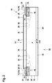
- Fig. 1 and 2 schematically show a cross-section through a power semiconductor module 10, which comprises a semiconductor wafer 12, to which power semiconductor chips 14 are bonded.
- the semiconductor wafer 12 comprises a base substrate made of Si, which may have a high resistance and/or may be slightly p--doped.
- the semiconductor wafer 12 is doped to form n-doped or n + -doped electrically conducting regions 18 and n-doped, or n + -doped field mitigation structures 20 that surround the electrically conducting regions 18.
- the semiconductor wafer 12 may be doped to form a p-doped or p + -doped layer 24, which may extend about the complete surface of the back side 22.
- the base substrate may be a high resistivity silicon wafer 12, which is n-doped below 5 ⁇ 10 12 / cm 3 or is p-doped below 1.7 ⁇ 10 13 / cm 3 with a thickness between 1 and 2.5 mm.
- the field blocking region 25 or field blocking layer 25 is formed between the electrical conductive patterns 18, 20 and the optional back layer 24 that has also such a doping.
- the field blocking region 25 may extend over the complete wideness of the semiconductor wafer 12.
- the electrical conductive patterns 18, 20 and/or the back layer 24 may be generated in the semiconductor wafer 12 by deep doping (implantation, diffusion, deposition and/or drive-in).
- a very high doped n + -region, such as the region 18, may be obtained by phosphorus deposition from POCL3 and subsequent drive-in.
- the thickness of the region 18 and/or the field mitigation structure 20 may be 10 to 50 ⁇ m, which for example may be the case after 2 to 25 hours of diffusion.
- the electrically conducting region 18 and/or the field mitigation structure 20 may be generated with a drift doping (Si) of 2 ⁇ 10 12 / cm 3 to 4 ⁇ 10 13 / cm 3 .
- a metallization layer 26 is formed, which may have a thickness capable of carrying the load current of the power semiconductor module 10.
- the metallization layer 26 may be a bond layer on which an electrical conductive sheet 28 is bonded, which may mainly carry the load current.
- the metallization or bond layer 26 may be a standard solderable or sinterable metallization like Ti/Ni/Ag, Ti/Ni/Au or Ti/Ni/Pt or, as a thick metallization, may be based also on Cu, Ag, or Al.
- the electrical conducting sheet may be a metal sheet, for example made of Cu, Al, Mo or Ag, or may be made of Graphene.
- the respective semiconductor chip 14 then may be either bonded to the metallization layer 26 or to the electrically conductive sheet 28.
- the surface of the semiconductor wafer 12 at the front side 16 may be coated with a passivation layer 30, either completely except the area, where the metallization layers 26 are formed, or at least besides the metallization layers 26 above the electrically conductive region 18 and the field mitigation structure 20.
- the passivation layer 30 may be one or more semi-insulating layers, like carbon based layers, glass, BCB (bisbenzocyclobutene), DLC (diamond like carbon), SiPOS (semi-insulating polycrystalline silicon) and/or polyimide, and/or may be used for chemical passivating the surface and/or for avoiding charging effects.
- semi-insulating layers like carbon based layers, glass, BCB (bisbenzocyclobutene), DLC (diamond like carbon), SiPOS (semi-insulating polycrystalline silicon) and/or polyimide, and/or may be used for chemical passivating the surface and/or for avoiding charging effects.
- the semiconductor wafer 12 may be coated with a back side bond layer 32, which may cover the complete back side surface of the semiconductor wafer 12.
- the semiconductor chips 14 may be transistors and/or thyristors, i.e. actively switchable switches and may form a half-bridge.
- the bottom side of the first semiconductor chip 14a may be interconnected via the metallization layer 26 and/or the electrically conducting sheet 28 below the first semiconductor chip 14a with a DC+ output 34 of the power semiconductor module 10.
- the top side of the first semiconductor chip 14a may be electrically interconnected with a conductor 33 with the metallization layer 26 and/or the electrically conducting sheet 28 below the second semiconductor chip 14b.
- This conductor 33 and/or the metallization layer 26 and/or the electrically conducting sheet 28 below the second semiconductor chip 14b may be interconnected with an AC output of the power semiconductor module 10.
- the top side of the second semiconductor chip 14b may be interconnected with a DC- output 38 of the power semiconductor module 10.
- the back layer 32 may be interconnected with a ground potential, indicated as GND and/or may be connected to a heatsink or cooler.
- a junction 40 is formed inside the semiconductor wafer 12, which provides mainly the blocking of high voltages.
- the field grading or field mitigation of the high electric fields present, when the power semiconductor module 10 is operating, is mainly provided inside the semiconductor wafer 12 at the junction 40.
- the junction 40 below the first semiconductor chip 14a is the main blocking junction.
- the junction 40 below the second semiconductor chip 14b is the main blocking junction.
- the field mitigation structure is provided by an electrically conducting region 42 with VLD (variation of lateral doping), which is in direct contact with the region 18.
- the region 42 may be a part of the region 18 having different doping.
- the region 18 may be n + -doped, while the region 42 may be n-doped.
- the field grading may be done in the semiconductor wafer 12 via a VLD termination.
- the region 42 may be provided besides the region 18.
- the region 42 may not be covered by the semiconductor chip 14.
- the level of doping in a region 42 may fall with raising distance to the region 18. Due to the varying resistance, a maximal value of the electric field at the junction 40 may be lowered.
- an electrically conducting runner 44 may be provided, which is also doped into the front side 16 of the semiconductor wafer 12 between two field mitigation structures 20.
- the runner 4 may be p-doped or p + -doped.
- the runner 44 which also may be seen as electrically conducting region, is inside the semiconductor wafer 12 and may be electrically disconnected from the regions 18, 42.
- the runner 44 may be electrically connected to DC- potential or to ground potential to yield a defined potential between the field mitigation structures 20.
- Fig. 2 shows a power semiconductor module 10 without such a runner 44.
- Fig. 3 and Fig. 4 show a cross-section through a power semiconductor module 10, which may be equally designed to the ones of Fig. 1 and 2 , but which have a different field mitigation structure in the form of field rings 46.
- Each field ring 46 may be an electrically conducting region or channel doped inside the front surface of the semiconductor wafer 12.
- the region 18 may be n + -doped, while the field rings 46 may be n-doped.
- the field rings 46 may be electrically disconnected from each other and/or from the region 18, at least inside the semiconductor wafer 12.
- the field rings 46 may surround the region 18 completely or partially (i.e. may be ring segments). Furthermore, the width of the field rings 46 in a lateral direction may decrease with increasing distance from the region 18.
- the field rings 46 may be floating, i.e. may be disconnected from any potential of the power semiconductor module. However, the field rings also may be biased, i.e. electrically connected to a potential, such as GND, DC+ or DC-.
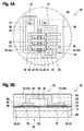
- Fig. 5A shows a further embodiment of a power semiconductor module 10 in a view from above.
- Fig. 5B shows a cross-section through the power semiconductor module of Fig. 5A .
- the power semiconductor module of Fig. 5A and 5B may be designed like the ones in Fig. 1 to Fig. 2 .
- the metallization layers 26 and electrically conducting regions 18 may be surrounded by a field mitigation structure 20, such as a field mitigation region 42 and/or field rings 46.
- a field mitigation region 42 is shown in Fig. 5B .
- field rings 46 may be used.
- a plurality of first semiconductor chips 14, 14a is bonded to the metallization layer 26 (or to a conducting sheet 28 on the metallization layer 26) below. Furthermore, on the AC side, a plurality of first semiconductor chips 14, 14a is bonded to the metallization layer 26 (or to a conducting sheet 28 on the metallization layer 26) below. Between the two rows of semiconductor chips 14 and between the corresponding field mitigation structures 20, two gate metallization layers 48 are arranged on the semiconductor wafer 12, which are connected via wire bonds 50 with the gate electrodes of the semiconductor chips 14 and with gate outputs 52 of the power semiconductor module 10.
- the top side of a first semiconductor 14, 14a is connected with a clip 33 with the metallization layer 26 (or to a conducting sheet 28 on the metallization layer 26) below the second semiconductor chips 14b.
- the clips 33 may have rounded edges with low curvature and/or a cross-section bigger than a bond wire 50.
- Fig. 5A also indicates that the originally round semiconductor wafer 12 may be cut to a substantially rectangular form 54.
- a DC- metallization layer 56 is shown which, like the other metallization layers 28, may be deposited on the front surface of the semiconductor wafer 12.
- the metallization layer 56 need not be positioned above an electrically conducting region doped into the semiconductor wafer 12 and/or need not be surrounded by a field mitigation structure.
- an electrically conducting sheet may be bonded on the metallization layer 56, analogously to the metallization layers 28, an electrically conducting sheet may be bonded.
- the metallization layer 56 may be interconnected with the top side of the second semiconductor chips with one or more clips 58, which may be designed analogously to the clips 33.
- the DC- output 36 may be interconnected with the metallization layer 56.
- the back side 22 of the semiconductor wafer 12 may be bonded to a metal body 60 that may act as a heat sink and as a mechanical support for the semiconductor wafer 12.
- the metal body 60 may be made of Molybdenum and/or may be Ag sintered to the back side bond layer 32 (see Fig. 1 to 4 ).
- the components on the front side 16 of the semiconductor wafer may be cast into an encapsulation 62, such as silicone gel or epoxy.
- encapsulation 62 such as silicone gel or epoxy.
- These encased components include the semiconductor chips 14, the metallization layers 26, the electrically conducting sheets 28, the clips 33 and the bond wires 50.
- Fig. 6A shows a further embodiment of a power semiconductor module 10 in a view from above.
- Fig. 6B shows a cross-section through the power semiconductor module of Fig. 5A .
- the embodiment of Fig. 6A and 6B may be designed analogously to the one of Fig. 5A and 5B , but has flip chips as second semiconductor chips 14b.
- the top side of the second semiconductor chips 14b is bonded via a metal spacer 64 to the metallization layer 26 and/or the electrically conducting sheet 28. Due to the metal spacer 64, the isolation of the semiconductor chip 14 may be better.
- the bottom side is bonded to the clip 33, which is also electrically interconnected with an AC-metallization layer 66, to which the AC output 36 is interconnected.
- the DC- output is interconnected with the metallization layer 26 below the second semiconductor chips 14b.
- the stray capacitance to GND of the AC metallization layer 66 may be lowered compared to Fig. 5A and 5B .
- the electrically conducting region 18 below the first semiconductor chips 14a and an electrically conducting region (doped in the semiconductor wafer 12 analogously to the region 18) below the metallization layer 66 are each surrounded by a field mitigation structure 20, which may be designed as described to the previous figures, for example as field mitigation region 42 and/or field rings 46.
- the region 18 below the second semiconductor chips 14b is not surrounded by a field mitigation structure.
- a passivation layer 30 As shown in Fig. 6B , only the area of the front surface of the semiconductor wafer with a field mitigation structure 20 may be covered with a passivation layer 30.
- Fig. 7 shows a power semiconductor module 10 with a housing 68, in which the semiconductor wafer 12 and the components attached to it, as described with respect to the previous figures, may be enclosed.
- the housing 68 may have power terminals 70a for the DC+ output 34, DC- output 38 and the AC output 36 as well as auxiliary terminals 70b for the gate outputs 52.
- the housing 68 of Fig. 7 may be made of plastics.
- Fig. 8 and 9 show a power semiconductor module 10 with a housing 68, in which the semiconductor wafer 12 and the components attached to it, as described with respect to the previous figures, may be enclosed.
- the housing 68 may be adapted for being stacked. I.e. two or more of the power semiconductor modules may be stacked onto each other, for example with interspaced cooling bodies, such that at least some of their power terminals 70a touch and are electrically interconnected.
- the housing 68 of Fig. 8 and 9 may be made of ceramics and/or may be hermetically sealed to avoid a moisture penetration to the sensitive termination areas. Furthermore, the housing 68 may have hermetically sealed ceramic feedthroughs for the terminals 70a, 70b.
- two power terminals 70a are arranged on opposite sides of the housing 68, which sides are flat and adapted for touching, when the module 10 is stacked.
- the power terminals 70a may be for DC+ and AC.
- a further power terminal 70a may be provided on a lateral side of the housing 68, for example for DC-.
- Fig. 9 two power terminals 70a (for example for DC+ and DC-) are arranged on the same side of the housing 68 and a third power terminal 70a (for example for AC) is arranged on the opposite side. As in Fig. 8 , these sides are flat and adapted for touching, when the module 10 is stacked.
- auxiliary terminals 70b for the gate outputs 52 may be provided in the lateral side of the housing 68.
Landscapes
- Electrodes Of Semiconductors (AREA)
- Chemical & Material Sciences (AREA)
- Engineering & Computer Science (AREA)
- Materials Engineering (AREA)
- Composite Materials (AREA)
- Physics & Mathematics (AREA)
- Geometry (AREA)
- Semiconductor Integrated Circuits (AREA)
Abstract
Description
- The invention relates to the field of packaging of power semiconductors. In particular, the invention relates to a power semiconductor module.
- Wide bandgap power devices, which, for example, may be based on SiC, may be realized with blocking voltages exceeding 20 kV to 30 kV. Such devices may provide a plurality of advantages compared to conventional Si substrate power devices. For example, the entire voltage range of medium voltage applications may be covered with simple two-level voltage source converter topologies. Furthermore, for typical two-level or three-level topologies in high voltage applications, the number of semiconductors in series connection may be reduced. For modular multi-level converters or cascaded half-bridge topologies in high voltage applications, the number of converter cells may be reduced. In general, this also may reduce the number of gate drivers and the number of stacked coolers and power modules.
- Additionally, the size of the wide bandgap devices and related modules may be reduced compared to the Si devices.
- Usually, for packaging power semiconductor chips, these chips are bonded to a substrate such as direct bonded Cu (DBC), active metal brazed Cu (AMB) or direct bonded Aluminum (DBA). It is common to these technologies that there is usually no field grading at sharp metallization edges and AMB braze protrusions, where the metallization stops and where a critical triple point between metal, ceramic and gel encapsulation is formed.
- Field grading may relate to mitigating a maximal field strength inside a power semiconductor module for avoiding partial discharges. There are many field grading approaches relating to ceramic substrates.
-
US 6,310,401 B1 relates to a linear resistive field grading realized by a resistive layer disposed on the ceramic. - In
US 2004/0140116 A1 , a resistive filler within a gel surround power electronics components is used for resistive field grading. - It is also known to use a polyimide coating dispensed on metallization edges and channels of ceramic substrates to increase the dielectric strength at the metallization edges. This may avoid partial discharges and may improve the mechanical strength of the Cu / ceramic interface.
- In
WO2011/080093 A1 , a nonlinear resistive field grading based on a micro-varistor filler material is proposed. - In
US 2001/0014413A1 andWO 01/04914A1 - Due to the partial discharge requirements for power semiconductor modules it is a challenge to scale metallized substrates for power devices above 6.5 kV which is the maximum blocking voltage of industrial applications today.
- When scaling power modules to very high voltages, methods of increasing the thicknesses of a ceramics substrate, on which the semiconductor chips are bonded, may not be promising due to their negative impact on the cooling of the power semiconductor devices and due to limited expected benefit since the peak electric field at a sharp electrode tip (of radius r) scales with the voltage ∼V/r rather than the distance to ground.
- Furthermore, field grading approaches outside the ceramics substrate or in an encapsulation, in which the semiconductor chips are immersed, such as resistive layers, high-permittivity fillers and non-linear resistive layers, may not be successful due to limited flexibility in field grading design and due to manufacturing issues of field grading layers and materials.
- It is an objective of the invention to provide a robust, industrial applicable power semiconductor module with high resistance against partial discharges that may be used for packaging wide bandgap semiconductor devices.
- This objective is achieved by the subject-matter of the independent claim. Further exemplary embodiments are evident from the dependent claims and the following description.
- The invention relates to a power semiconductor module. A power semiconductor module may be a device comprising one or more power semiconductor chips and further components for electrically connecting and mechanically supporting the one or more power semiconductor chips. Furthermore, a power semiconductor module may comprise a housing and/or encapsulation, in which the one or more power semiconductor chips are accommodated.
- The term "power" here and in the following may refer to a module and/or semiconductor chips adapted for processing currents of more than 10 A and/or more than 1 kV.
- According to an embodiment of the invention, the power semiconductor module comprises: at least one power semiconductor chip providing a power electronics switch and a semiconductor wafer, to which the at least one power semiconductor chip is bonded, wherein the semiconductor wafer is doped, such that it comprises a field blocking region and an electrically conducting region on the field blocking region, to which electrically conducting region the at least one power semiconductor chip is bonded. Bonding may refer to soldering, sintering, gluing or other types of attachment.
- In other words, the semiconductor wafer may be used as a substrate for electrically insulating and mechanically supporting the at least one power semiconductor chip and/or for providing field grading at edges of electrically conductive areas of high voltage electrical potential on which the power semiconductor chips are attached to. An electrical field generated by the power semiconductor module layout with electrically conductive areas on different potential is attenuated/mitigated inside the semiconductor wafer. It may be possible that the highest field strength is generated inside the semiconductor wafer at a junction between differently doped regions, where partial discharges may be suppressed very strongly.
- The semiconductor wafer may be a Si or SiC wafer. Such a wafer may be very well suited as a substrate, since it may have an excellent CTE match to all power semiconductor materials (for example to allow for high reliability bond interfaces). In particular, the semiconductor wafer may be made of the same material as the semiconductor chip.
- Furthermore, a semiconductor wafer may have an excellent thermal conductivity for heat spreading and cooling of power devices (such as of 150 W/mK for a Si wafer).
- The power semiconductor chip may be a conventional Si based chip. The power semiconductor chip also may provide a wide bandgap device and/or may be based on SiC or GaN. The power electronics switch of the semiconductor chip may be a transistor, thyristor or diode.
- Summarized, according to an embodiment of the invention, the semiconductor wafer is made from Si or from SiC, and the semiconductor chip provides a wide bandgap electronics component. In particular, the power semiconductor module may be adapted for processing voltages of more than 10 kV that may be switched by wide bandgap electronics components, such as transistors and diodes.
- For example, the semiconductor wafer may be made of a base substrate, which is doped to generate the electrically conducting region. The electrically conducting region may be formed in an upper part of the semiconductor wafer. In particular, the electrically conducting region may be provided on a top surface of the semiconductor wafer.
- The electrically conducting region may be seen as a vertical voltage blocking structure, which moves high field gradients and/or high field strength inside the semiconductor wafer.
- The base substrate may be a semiconductor substrate which is n-doped below 5·1012 / cm3 or is p-doped below 1.7·1013 / cm3. The field blocking region also may be doped in such a way. The electrically conducting region may be n-doped much higher, for example may comprise 100 times more charge carriers. The field blocking region may be a layer of the semiconductor wafer that may be a substantially insulating layer.
- The semiconductor chip may be arranged above the electrically conducting region and/or may be bonded to the electrically conducting region. It has to be noted that the semiconductor chip directly may be bonded to a metallization layer provided on the electrically conducting region or may be bonded to other electrically conducting elements, which may be bonded to such a metallization layer.
- According to an embodiment of the invention, the semiconductor wafer is doped, such that the electrically conducting region is surrounded by a field mitigation structure adapted for lowering a maximal electrical field strength in the semiconductor wafer. For example, the field mitigation structure, which also may be provided in an upper part and/or at the top surface of the semiconductor wafer, which may be doped in the same way (i.e. n-doped or p-doped) as the electrically conducting region. Doping of the electrically conducting region and the field mitigation structure may be based on implantation doping, diffusion doping, deposition doping and optionally followed by drive-in or activation.
- The field mitigation structure also may be seen as an edge termination structure for the edge of the electrically conducting region.
- According to an embodiment of the invention, the field mitigation structure comprises an electrically conducting field mitigation region with a doping that varies dependent on a distance to the electrically conducting region. For example, the n doping of the field mitigation region may become smaller with raising horizontal distance from the electrically conducting region. Such a field mitigation region may be generated with a VLD (variation of lateral doping) process.
- According to an embodiment of the invention, the field mitigation region is in electrical contact with the electrically conducting region, in particular inside the semiconductor wafer. In such a way, resistive field mitigation may take place in the field mitigation region.
- According to an embodiment of the invention, the field mitigation structure comprises a number of electrically conducting rings (which may be called field rings) electrically isolated from the electrically conducting region, at least inside the semiconductor wafer. It may be possible that the rings are surrounding the electrically conducting region solely partially. However, it also may be possible that the rings are closed.
- It may be that the rings are higher doped than the electrically conducting region. For example, the electrically conducting region may be n-doped, wherein the rings are formed from n-doped or n+- doped regions.
- Here, in the above and in the following, the signs "+" and "-" may refer to doping about 10 to 100 times higher and/or lower with respect to doping without "+" or "-". For example, an n+-doped region may be doped 10 to 100 times higher than an n-doped region, which may be doped 10 to 100 times higher than an n--doped region.
- It also may be that a ring width of the rings is constant or varies with respect to a distance of the ring to the electrically conducting region. For example, the ring width may decrease with raising distance from the electrically conducting region.
- It also may be that a ring depth of the rings is shallower or deeper than the electrically conducting region.
- The field rings may be floating or at least partially biased.
- According to an embodiment of the invention, the field rings are electrically floating. I.e. they are not connected to a conductor of the power semiconductor module, which, during operation of the power semiconductor module, provides a specific potential (such as ground or DC+ or DC-).
- According to an embodiment of the invention, the field rings are at least partially electrically connected to an electric potential provided by the power semiconductor module. For example, the field rings may be connected partially via a semi-insulating layer to the electrical potential.
- According to an embodiment of the invention, the electrically conducting region is n-doped, wherein the field mitigation region surrounding the electrically conducting region is lesser n-doped than the electrically conducting region and/or wherein the field rings surrounding the electrically conducting region are lesser n-doped than the electrically conducting region.
- According to an embodiment of the invention, a passivation layer is provided on a surface of the semiconductor wafer above the electrically conducting region. This passivation layer may at least be provided besides the semiconductor chip and/or may be provided above the field mitigation structure. For example, the passivation layer, which may protect the surface of the semiconductor wafer from chemical degrading, may be made of a polyimide.
- According to an embodiment of the invention, the semiconductor wafer is doped such that between two electrically conducting regions, to which semiconductor chips are bonded, an electrically conducting runner is provided, which is connected to an electric potential provided by the power semiconductor module. The runner may be an electrically conducting region between two field mitigation structures, which is electrically isolated from the field mitigation structures. The runner may be connected to DC- or to ground potential. The runner also may be generated by doping the semiconductor wafer. For example, the runner may be p-doped or p+-doped. With such a runner, a leakage current from the electrically conducting regions below the semiconductor chip may be reduced.
- According to an embodiment of the invention, the semiconductor wafer comprises a back layer higher p-doped than the central field blocking region. For example, the doping at the back side of the semiconductor wafer may be p+, p or p-. To this back layer, a metallization layer, which may cover the complete back side of the semiconductor wafer, may be attached.
- According to an embodiment of the invention, the field blocking region of the semiconductor wafer has a thickness of more than 1 mm (for example between 1 mm and 2.5 mm) and/or the electrically conducting region has a thickness between 10 to 50 µm. In other words, the electrically conducting region may be much thinner than the field blocking region.
- According to an embodiment of the invention, the power semiconductor module further comprises: a metallization layer on the electrically conducting region, to which the semiconductor chip is electrically connected. Such a metallization layer may be added for bonding the semiconductor chip and/or electrically conducting sheets.
- According to an embodiment of the invention, an electrically conducting sheet is bonded to the metallization layer. The electrically conducting sheet may be much thicker, for example more than 10 times thicker, than the metallization layer on the electrically conducting region. The electrically conducting sheet may be made of Cu, Al, Ag, Mo or Graphene.
- Furthermore, a metallization layer on the back side of the semiconductor wafer, i.e. on a side opposite to the side, where the electrically conducting region is provided, may be provided. To this metallization layer, a further metal sheet or metal body, such as a body of Molybdenum, may be bonded, which may act as mechanical support and/or as heat sink.
- According to an embodiment of the invention, the power semiconductor module comprises a metal body to which the semiconductor wafer is bonded with a back side.
- According to an embodiment of the invention, the semiconductor chip is bonded to a metallization layer on the conducting region or to an electrically conducting sheet bonded to the metallization layer. As already mentioned, the semiconductor chip may be directly bonded to the metallization layer or indirectly via an additional electrically conducting body.
- It may be possible that the power semiconductor module carries and/or comprises a circuit of more than one power semiconductor switch. For example, the power semiconductor module may comprise a half-bridge.
- A half-bridge may comprise one or more first semiconductor switches (which may be connected in parallel), which are connected in series with one or more second semiconductor switches (which may be connected in parallel). The one or more first semiconductor switches may be provided by one or more first semiconductor chips. The one or more second semiconductor switches may be provided by one or more second semiconductor chips.
- According to an embodiment of the invention, the power semiconductor module may comprise a half-bridge with all semiconductor chips bonded to the semiconductor wafer in the same direction. Here, and in the following, the direction of a semiconductor chip refers to its power electrodes (such as base, drain, etc.). Chips of the same direction are bonded with the same power electrode to the semiconductor wafer.
- According to an embodiment of the invention, the power semiconductor module further comprises a DC+ conducting region doped into the semiconductor wafer, to which at least one first semiconductor chip is bonded, which DC+ conducting region is surrounded by a field mitigation structure doped into the semiconductor wafer, an AC conducting region doped into the semiconductor wafer, to which at least one second semiconductor chip is bonded, which DC+ conducting region is surrounded by a field mitigation structure doped into the semiconductor wafer, wherein the AC conducting region is electrically connected to a top side of the first semiconductor chip, and a DC- metallization layer electrically connected to a top side of the second semiconductor chip.
- According to an embodiment of the invention, the power semiconductor module may comprise a half-bridge with the second semiconductor chips bonded to the semiconductor wafer in the reverse direction of the first semiconductor chips. The second semiconductor chips may be seen as flip chips. For example, such a configuration may result in no or only a small AC metallization layer on the semiconductor wafer.
- According to an embodiment of the invention, the power semiconductor module further comprises a DC+ conducting region doped into the semiconductor wafer, to which at least one first semiconductor chip is bonded, which DC+ conducting region is surrounded by a field mitigation structure doped into the semiconductor wafer; a DC- conducting layer, to which at least one second semiconductor chip is bonded in a reverse direction with respect to the first semiconductor chip; and an AC conducting region doped into the semiconductor wafer, which AC conducting region is surrounded by a field mitigation structure doped into the semiconductor wafer and which AC conducting region is electrically connected to a top side of the at least one first semiconductor chip and to a top side of the second semiconductor chip.
- It may be that an electrically conducting spacer is arranged between a second, flip chip and the corresponding metallization layer.
- In all configurations, the semiconductor chip may be electrically interconnected with another semiconductor chip or a metallization layer or another electrically conducting region by an electrically conducting clip, which is attached to the top side of the semiconductor chip. The clip may have large diameters and low curvature compared to a bond wire to avoid discharges.
- According to an embodiment of the invention, the power semiconductor module further comprises a housing surrounding the semiconductor wafer and the at least one semiconductor chip, the housing accommodating an encapsulation covering a front side of the semiconductor wafer and covering the at least one semiconductor chip. For example, the encapsulation may be potted into the housing.
- These and other aspects of the invention will be apparent from and elucidated with reference to the embodiments described hereinafter.
- The subject matter of the invention will be explained in more detail in the following text with reference to exemplary embodiments which are illustrated in the attached drawings.
-
Fig. 1 schematically shows a cross-section through a power semiconductor module according to an embodiment of the invention. -
Fig. 2 schematically shows a cross-section through a power semiconductor module according to a further embodiment of the invention. -
Fig. 3 schematically shows a cross-section through a power semiconductor module according to a further embodiment of the invention. -
Fig. 4 schematically shows a cross-section through a power semiconductor module according to a further embodiment of the invention. -
Fig. 5A schematically shows a top view on a power semiconductor module according to a further embodiment of the invention. -
Fig. 5B schematically shows a cross-section through the power semiconductor module ofFig. 5A . -
Fig. 6A schematically shows a top view on a power semiconductor module according to a further embodiment of the invention. -
Fig. 6B schematically shows a cross-section through the power semiconductor module ofFig. 6A . -
Fig. 7 schematically shows a perspective view of a housing of a power semiconductor module according to a further embodiment of the invention. -
Fig. 8 schematically shows a perspective view of a housing of a power semiconductor module according to a further embodiment of the invention. -
Fig. 9 schematically shows a perspective view of a housing of a power semiconductor module according to a further embodiment of the invention. - The reference symbols used in the drawings, and their meanings, are listed in summary form in the list of reference symbols. In principle, identical parts are provided with the same reference symbols in the figures.
-
Fig. 1 and2 schematically show a cross-section through apower semiconductor module 10, which comprises asemiconductor wafer 12, to which power semiconductor chips 14 are bonded. - The
semiconductor wafer 12 comprises a base substrate made of Si, which may have a high resistance and/or may be slightly p--doped. On afront side 16, thesemiconductor wafer 12 is doped to form n-doped or n+-doped electrically conductingregions 18 and n-doped, or n+-dopedfield mitigation structures 20 that surround the electrically conductingregions 18. - On a
back side 22, thesemiconductor wafer 12 may be doped to form a p-doped or p+-dopedlayer 24, which may extend about the complete surface of theback side 22. - For example, the base substrate may be a high
resistivity silicon wafer 12, which is n-doped below 5·1012 / cm3 or is p-doped below 1.7·1013 / cm3 with a thickness between 1 and 2.5 mm. Thefield blocking region 25 orfield blocking layer 25 is formed between the electricalconductive patterns optional back layer 24 that has also such a doping. Thefield blocking region 25 may extend over the complete wideness of thesemiconductor wafer 12. - The electrical
conductive patterns back layer 24 may be generated in thesemiconductor wafer 12 by deep doping (implantation, diffusion, deposition and/or drive-in). For example, a very high doped n+-region, such as theregion 18, may be obtained by phosphorus deposition from POCL3 and subsequent drive-in. The thickness of theregion 18 and/or thefield mitigation structure 20 may be 10 to 50 µm, which for example may be the case after 2 to 25 hours of diffusion. - For example, for achieving voltage blocking capabilities of about 20 kV, the electrically conducting
region 18 and/or thefield mitigation structure 20 may be generated with a drift doping (Si) of 2·1012 / cm3 to 4·1013 / cm3. - On every electrical
conductive region 18, ametallization layer 26 is formed, which may have a thickness capable of carrying the load current of thepower semiconductor module 10. Alternatively, themetallization layer 26 may be a bond layer on which an electricalconductive sheet 28 is bonded, which may mainly carry the load current. The metallization orbond layer 26 may be a standard solderable or sinterable metallization like Ti/Ni/Ag, Ti/Ni/Au or Ti/Ni/Pt or, as a thick metallization, may be based also on Cu, Ag, or Al. The electrical conducting sheet may be a metal sheet, for example made of Cu, Al, Mo or Ag, or may be made of Graphene. - The respective semiconductor chip 14 then may be either bonded to the
metallization layer 26 or to the electricallyconductive sheet 28. - The surface of the
semiconductor wafer 12 at thefront side 16 may be coated with apassivation layer 30, either completely except the area, where the metallization layers 26 are formed, or at least besides the metallization layers 26 above the electricallyconductive region 18 and thefield mitigation structure 20. - The
passivation layer 30 may be one or more semi-insulating layers, like carbon based layers, glass, BCB (bisbenzocyclobutene), DLC (diamond like carbon), SiPOS (semi-insulating polycrystalline silicon) and/or polyimide, and/or may be used for chemical passivating the surface and/or for avoiding charging effects. - On the
back side 22, thesemiconductor wafer 12 may be coated with a backside bond layer 32, which may cover the complete back side surface of thesemiconductor wafer 12. - The semiconductor chips 14 may be transistors and/or thyristors, i.e. actively switchable switches and may form a half-bridge. The bottom side of the first semiconductor chip 14a may be interconnected via the
metallization layer 26 and/or the electrically conductingsheet 28 below the first semiconductor chip 14a with aDC+ output 34 of thepower semiconductor module 10. The top side of the first semiconductor chip 14a may be electrically interconnected with aconductor 33 with themetallization layer 26 and/or the electrically conductingsheet 28 below the second semiconductor chip 14b. Thisconductor 33 and/or themetallization layer 26 and/or the electrically conductingsheet 28 below the second semiconductor chip 14b may be interconnected with an AC output of thepower semiconductor module 10. The top side of the second semiconductor chip 14b may be interconnected with a DC-output 38 of thepower semiconductor module 10. - The
back layer 32 may be interconnected with a ground potential, indicated as GND and/or may be connected to a heatsink or cooler. - Due to the doping, a
junction 40 is formed inside thesemiconductor wafer 12, which provides mainly the blocking of high voltages. The field grading or field mitigation of the high electric fields present, when thepower semiconductor module 10 is operating, is mainly provided inside thesemiconductor wafer 12 at thejunction 40. - When the
DC+ output 34 is at positive potential compared to theAC output 36, which then is at ground potential (GND), thejunction 40 below the first semiconductor chip 14a is the main blocking junction. When theAC output 36 is at positive potential compared to the DC-output 38, thejunction 40 below the second semiconductor chip 14b is the main blocking junction. - In
Fig. 1 and2 , the field mitigation structure is provided by an electrically conductingregion 42 with VLD (variation of lateral doping), which is in direct contact with theregion 18. In general, theregion 42 may be a part of theregion 18 having different doping. For example, theregion 18 may be n+-doped, while theregion 42 may be n-doped. The field grading may be done in thesemiconductor wafer 12 via a VLD termination. - While the
region 18 extends below the corresponding semiconductor chip 14, theregion 42 may be provided besides theregion 18. Theregion 42 may not be covered by the semiconductor chip 14. - For example, the level of doping in a
region 42 may fall with raising distance to theregion 18. Due to the varying resistance, a maximal value of the electric field at thejunction 40 may be lowered. - As shown in
Fig. 1 , an electrically conductingrunner 44 may be provided, which is also doped into thefront side 16 of thesemiconductor wafer 12 between twofield mitigation structures 20. For example, the runner 4 may be p-doped or p+-doped. Therunner 44, which also may be seen as electrically conducting region, is inside thesemiconductor wafer 12 and may be electrically disconnected from theregions runner 44 may be electrically connected to DC- potential or to ground potential to yield a defined potential between thefield mitigation structures 20. -
Fig. 2 shows apower semiconductor module 10 without such arunner 44. -
Fig. 3 andFig. 4 show a cross-section through apower semiconductor module 10, which may be equally designed to the ones ofFig. 1 and2 , but which have a different field mitigation structure in the form of field rings 46. - Each field ring 46 may be an electrically conducting region or channel doped inside the front surface of the
semiconductor wafer 12. For example, theregion 18 may be n+-doped, while the field rings 46 may be n-doped. - The field rings 46 may be electrically disconnected from each other and/or from the
region 18, at least inside thesemiconductor wafer 12. The field rings 46 may surround theregion 18 completely or partially (i.e. may be ring segments). Furthermore, the width of the field rings 46 in a lateral direction may decrease with increasing distance from theregion 18. - The field rings 46 may be floating, i.e. may be disconnected from any potential of the power semiconductor module. However, the field rings also may be biased, i.e. electrically connected to a potential, such as GND, DC+ or DC-.
-
Fig. 5A shows a further embodiment of apower semiconductor module 10 in a view from above.Fig. 5B shows a cross-section through the power semiconductor module ofFig. 5A . - The power semiconductor module of
Fig. 5A and 5B may be designed like the ones inFig. 1 to Fig. 2 . The metallization layers 26 and electrically conductingregions 18 may be surrounded by afield mitigation structure 20, such as afield mitigation region 42 and/or field rings 46. InFig. 5B , afield mitigation region 42 is shown. Here, however, also alternatively or additionally field rings 46 may be used. - On the DC+ side, a plurality of first semiconductor chips 14, 14a is bonded to the metallization layer 26 (or to a conducting
sheet 28 on the metallization layer 26) below. Furthermore, on the AC side, a plurality of first semiconductor chips 14, 14a is bonded to the metallization layer 26 (or to a conductingsheet 28 on the metallization layer 26) below. Between the two rows of semiconductor chips 14 and between the correspondingfield mitigation structures 20, two gate metallization layers 48 are arranged on thesemiconductor wafer 12, which are connected viawire bonds 50 with the gate electrodes of the semiconductor chips 14 and withgate outputs 52 of thepower semiconductor module 10. - The top side of a first semiconductor 14, 14a is connected with a
clip 33 with the metallization layer 26 (or to a conductingsheet 28 on the metallization layer 26) below the second semiconductor chips 14b. As shown inFig. 5 , theclips 33 may have rounded edges with low curvature and/or a cross-section bigger than abond wire 50. -
Fig. 5A also indicates that the originallyround semiconductor wafer 12 may be cut to a substantiallyrectangular form 54. - In
Fig. 5A , a DC-metallization layer 56 is shown which, like the other metallization layers 28, may be deposited on the front surface of thesemiconductor wafer 12. Themetallization layer 56 need not be positioned above an electrically conducting region doped into thesemiconductor wafer 12 and/or need not be surrounded by a field mitigation structure. On themetallization layer 56, analogously to the metallization layers 28, an electrically conducting sheet may be bonded. Themetallization layer 56 may be interconnected with the top side of the second semiconductor chips with one ormore clips 58, which may be designed analogously to theclips 33. Furthermore, the DC-output 36 may be interconnected with themetallization layer 56. - In
Fig. 5B it is shown that theback side 22 of thesemiconductor wafer 12 may be bonded to ametal body 60 that may act as a heat sink and as a mechanical support for thesemiconductor wafer 12. For example, themetal body 60 may be made of Molybdenum and/or may be Ag sintered to the back side bond layer 32 (seeFig. 1 to 4 ). - Furthermore, the components on the
front side 16 of the semiconductor wafer may be cast into anencapsulation 62, such as silicone gel or epoxy. These encased components include the semiconductor chips 14, the metallization layers 26, the electrically conductingsheets 28, theclips 33 and thebond wires 50. -
Fig. 6A shows a further embodiment of apower semiconductor module 10 in a view from above.Fig. 6B shows a cross-section through the power semiconductor module ofFig. 5A . The embodiment ofFig. 6A and 6B may be designed analogously to the one ofFig. 5A and 5B , but has flip chips as second semiconductor chips 14b. - In
Fig. 6A and 6B , the top side of the second semiconductor chips 14b is bonded via a metal spacer 64 to themetallization layer 26 and/or the electrically conductingsheet 28. Due to the metal spacer 64, the isolation of the semiconductor chip 14 may be better. The bottom side is bonded to theclip 33, which is also electrically interconnected with an AC-metallization layer 66, to which theAC output 36 is interconnected. The DC- output is interconnected with themetallization layer 26 below the second semiconductor chips 14b. - Due to the design of
Fig. 6A and 6B , the stray capacitance to GND of theAC metallization layer 66 may be lowered compared toFig. 5A and 5B . - In
Fig. 6A and 6B , the electrically conductingregion 18 below the first semiconductor chips 14a and an electrically conducting region (doped in thesemiconductor wafer 12 analogously to the region 18) below themetallization layer 66 are each surrounded by afield mitigation structure 20, which may be designed as described to the previous figures, for example asfield mitigation region 42 and/or field rings 46. - The
region 18 below the second semiconductor chips 14b is not surrounded by a field mitigation structure. - As shown in
Fig. 6B , only the area of the front surface of the semiconductor wafer with afield mitigation structure 20 may be covered with apassivation layer 30. -
Fig. 7 shows apower semiconductor module 10 with ahousing 68, in which thesemiconductor wafer 12 and the components attached to it, as described with respect to the previous figures, may be enclosed. On one side, thehousing 68 may have power terminals 70a for theDC+ output 34, DC-output 38 and theAC output 36 as well as auxiliary terminals 70b for the gate outputs 52. Thehousing 68 ofFig. 7 may be made of plastics. -
Fig. 8 and9 show apower semiconductor module 10 with ahousing 68, in which thesemiconductor wafer 12 and the components attached to it, as described with respect to the previous figures, may be enclosed. Thehousing 68 may be adapted for being stacked. I.e. two or more of the power semiconductor modules may be stacked onto each other, for example with interspaced cooling bodies, such that at least some of their power terminals 70a touch and are electrically interconnected. - The
housing 68 ofFig. 8 and9 may be made of ceramics and/or may be hermetically sealed to avoid a moisture penetration to the sensitive termination areas. Furthermore, thehousing 68 may have hermetically sealed ceramic feedthroughs for the terminals 70a, 70b. - In
Fig. 8 , two power terminals 70a are arranged on opposite sides of thehousing 68, which sides are flat and adapted for touching, when themodule 10 is stacked. For example, the power terminals 70a may be for DC+ and AC. A further power terminal 70a may be provided on a lateral side of thehousing 68, for example for DC-. - In
Fig. 9 , two power terminals 70a (for example for DC+ and DC-) are arranged on the same side of thehousing 68 and a third power terminal 70a (for example for AC) is arranged on the opposite side. As inFig. 8 , these sides are flat and adapted for touching, when themodule 10 is stacked. - In both
Fig. 8 and9 , auxiliary terminals 70b for the gate outputs 52 may be provided in the lateral side of thehousing 68. - While the invention has been illustrated and described in detail in the drawings and foregoing description, such illustration and description are to be considered illustrative or exemplary and not restrictive; the invention is not limited to the disclosed embodiments. Other variations to the disclosed embodiments can be understood and effected by those skilled in the art and practising the claimed invention, from a study of the drawings, the disclosure, and the appended claims. In the claims, the word "comprising" does not exclude other elements or steps, and the indefinite article "a" or "an" does not exclude a plurality. A single processor or controller or other unit may fulfil the functions of several items recited in the claims. The mere fact that certain measures are recited in mutually different dependent claims does not indicate that a combination of these measures cannot be used to advantage. Any reference signs in the claims should not be construed as limiting the scope.
-
- 10
- power semiconductor module
- 12
- semiconductor wafer
- 14
- semiconductor chip
- 16
- front side
- 18
- electrically conducting region
- 20
- field mitigation structure
- 22
- back side
- 24
- back layer
- 25
- field blocking region
- 26
- metallization/bond layer
- 28
- electrically conducting sheet
- 30
- passivation layer
- 32
- bond layer
- 33
- conductor / clip
- 34
- DC+ output
- 36
- AC output
- 38
- DC- output
- 40
- junction
- 42
- field mitigation region
- 44
- electrically conducting runner
- 46
- field ring
- 48
- gate metallization layer
- 50
- bond wire
- 52
- gate output
- 54
- rectangular form
- 56
- metallization layer
- 58
- clip
- 60
- metal body
- 62
- encapsulation
- 64
- metal spacer
- 66
- metallization layer
- 68
- housing
- 70a
- power terminal
- 70b
- auxiliary terminal
Claims (18)
- A power semiconductor module (10), comprising:at least one power semiconductor chip (14) providing a power electronics switch;a semiconductor wafer (12), to which the at least one power semiconductor chip (14) is bonded;wherein the semiconductor wafer (12) is doped, such that it comprises a field blocking region (25) and an electrically conducting region (18) on the field blocking region (25), to which electrically conducting region (18) the at least one power semiconductor chip (14) is bonded.
- The power semiconductor module (10) of claim 1,
wherein the semiconductor wafer (12) is doped, such that the electrically conducting region (18) is surrounded by a field mitigation structure (20) adapted for lowering a maximal electrical field strength in the semiconductor wafer (12). - The power semiconductor module (10) of claim 2,
wherein the field mitigation structure (20) comprises an electrically conducting field mitigation region (42) with a doping that varies dependent on a distance to the electrically conducting region (18). - The power semiconductor module (10) of claim 3,
wherein the field mitigation region (42) is in electrical contact with the electrically conducting region (18). - The power semiconductor module (10) of one of claims 2 to 4,
wherein the field mitigation structure (20) comprises a number of electrically conducting field rings (46) electrically isolated from the electrically conducting region (18). - The power semiconductor module (10) of claim 5,
wherein the field rings (46) are electrically floating; or
wherein the field rings (46) are connected at least partially to an electric potential (DC+, AC) provided by the power semiconductor module (10). - The power semiconductor module (10) of one of the preceding claims,
wherein a passivation layer (30) is provided on a surface of the semiconductor wafer (12) above the electrically conducting region (18). - The power semiconductor module (10) of one of the preceding claims,
wherein the electrically conducting (18) region is n-doped; or
wherein a field mitigation region (42) surrounding the electrically conducting region (18) is lesser n-doped than the electrically conducting region (18); and/or
wherein field rings (46) surrounding the electrically conducting region (18) are lesser n-doped than the electrically conducting region (18). - The power semiconductor module (10) of one of the preceding claims,
wherein the semiconductor wafer (12) is doped such that between two electrically conducting regions (18), to which semiconductor chips (14) are bonded, an electrically conducting runner (44) is provided, which is connected to an electric potential (DC-, GND) provided by the power semiconductor module (10). - The power semiconductor module (10) of one of the preceding claims,
wherein the semiconductor wafer (12) comprises a back layer (24) higher p-doped than the central field blocking region (25). - The power semiconductor module (10) of one of the preceding claims,
wherein the field blocking region (25) of the semiconductor wafer (12) has a thickness of more than 1 mm; and/or
wherein the electrically conducting region (18) has a thickness between 10 to 50 µm. - The power semiconductor module (10) of one of the preceding claims, further comprising:a metallization layer (26) on the electrically conducting region (18), to which the semiconductor chip (14) is electrically connected.
- The power semiconductor module (10) of one of the preceding claims,
wherein an electrically conducting sheet (28) is bonded to the metallization layer (26); and/or
wherein the electrically conducting sheet (28) is made of Cu, Al, Mo, Ag or Graphene. - The power semiconductor module (10) of one of the preceding claims,
wherein the semiconductor chip (14) is bonded to a metallization layer (26) on the electrically conducting region (18) or to an electrically conducting sheet (28) bonded to the metallization layer (26). - The power semiconductor module (10) of one of the preceding claims,
wherein the semiconductor wafer (12) is made from Si or from SiC, and/or
wherein the semiconductor chip (14) provides a wide bandgap electronics component. - The power semiconductor module (10) of one of the preceding claims, further comprising:a DC+ conducting region (18) doped into the semiconductor wafer (12), to which at least one first semiconductor chip (14a) is bonded, which DC+ conducting region (18) is surrounded by a field mitigation structure (20) doped into the semiconductor wafer (12);an AC conducting region (18) doped into the semiconductor wafer (12), to which at least one second semiconductor chip (14b) is bonded, which DC+ conducting region (18) is surrounded by a field mitigation structure (20) doped into the semiconductor wafer (12), wherein the AC conducting region (18) is electrically connected to a top side of the first semiconductor chip (14a);a DC- metallization layer (56) electrically connected to a top side of the second semiconductor chip (14b).
- The power semiconductor module (10) of one of the preceding claims, further comprising:a DC+ conducting region (18) doped into the semiconductor wafer (12), to which at least one first semiconductor chip (14a) is bonded, which DC+ conducting region (18) is surrounded by a field mitigation structure (20) doped into the semiconductor wafer (12);a DC- conducting region (18), to which at least one second semiconductor chip (14b) is bonded in a reverse direction with respect to the first semiconductor chip (14a);an AC conducting region doped into the semiconductor wafer, which AC conducting region is surrounded by a field mitigation structure (20) doped into the semiconductor wafer (12) and which AC conducting region is electrically connected to a top side of the at least one first semiconductor chip (14a) and to a top side of the second semiconductor chip (14b).
- The power semiconductor module (10) of one of the preceding claims, further comprising:a metal body (60) to which the semiconductor wafer (12) is bonded with a back side (22); and/ora housing (68) surrounding the semiconductor wafer (12) and the at least one semiconductor chip (14), the housing (68) accommodating an encapsulation (62) covering a front side (16) of the semiconductor wafer (12) and covering the at least one semiconductor chip (14).
Priority Applications (4)
| Application Number | Priority Date | Filing Date | Title |
|---|---|---|---|
| EP16182374.5A EP3279935B1 (en) | 2016-08-02 | 2016-08-02 | Power semiconductor module |
| JP2017146418A JP7043196B2 (en) | 2016-08-02 | 2017-07-28 | Power semiconductor module |
| US15/666,858 US11107740B2 (en) | 2016-08-02 | 2017-08-02 | Power semiconductor module |
| CN201710652090.6A CN107680944B (en) | 2016-08-02 | 2017-08-02 | Power semiconductor module |
Applications Claiming Priority (1)
| Application Number | Priority Date | Filing Date | Title |
|---|---|---|---|
| EP16182374.5A EP3279935B1 (en) | 2016-08-02 | 2016-08-02 | Power semiconductor module |
Publications (2)
| Publication Number | Publication Date |
|---|---|
| EP3279935A1 true EP3279935A1 (en) | 2018-02-07 |
| EP3279935B1 EP3279935B1 (en) | 2019-01-02 |
Family
ID=56561301
Family Applications (1)
| Application Number | Title | Priority Date | Filing Date |
|---|---|---|---|
| EP16182374.5A Active EP3279935B1 (en) | 2016-08-02 | 2016-08-02 | Power semiconductor module |
Country Status (4)
| Country | Link |
|---|---|
| US (1) | US11107740B2 (en) |
| EP (1) | EP3279935B1 (en) |
| JP (1) | JP7043196B2 (en) |
| CN (1) | CN107680944B (en) |
Cited By (2)
| Publication number | Priority date | Publication date | Assignee | Title |
|---|---|---|---|---|
| US20180040526A1 (en) * | 2016-08-02 | 2018-02-08 | Abb Schweiz Ag | Power semiconductor module |
| WO2021130290A1 (en) * | 2019-12-28 | 2021-07-01 | Danfoss Silicon Power Gmbh | Power module with improved electrical characteristics |
Families Citing this family (4)
| Publication number | Priority date | Publication date | Assignee | Title |
|---|---|---|---|---|
| KR102149197B1 (en) * | 2013-08-26 | 2020-08-28 | 엘지전자 주식회사 | Refrigerator |
| CN109724721A (en) * | 2019-01-21 | 2019-05-07 | 武汉大学 | SiC high temperature pressure sensor with leadless package and its manufacturing method |
| CN112185941B (en) * | 2020-09-28 | 2024-11-08 | 苏州汇川联合动力系统股份有限公司 | Semiconductor packaging, motor controllers and new energy vehicles |
| US20250040179A1 (en) * | 2023-07-30 | 2025-01-30 | Texas Instruments Incorporated | Semiconductor device with a high k field relief dielectric structure |
Citations (8)
| Publication number | Priority date | Publication date | Assignee | Title |
|---|---|---|---|---|
| EP0411595A2 (en) * | 1989-07-31 | 1991-02-06 | Siemens Aktiengesellschaft | Process for bonding semiconductor chips to a wafer |
| WO2001004914A1 (en) | 1999-07-07 | 2001-01-18 | Abb Research Ltd. | Electrical component with disconnection of electrical field excesses |
| JP2001057409A (en) * | 1999-08-17 | 2001-02-27 | Hitachi Ltd | Semiconductor device |
| US20010014413A1 (en) | 1998-08-05 | 2001-08-16 | Lefranc Guy | Substrate for high-voltage modules |
| US6310401B1 (en) | 1999-06-22 | 2001-10-30 | Siemens Aktiengesellschaft | Substrate for high-voltage modules |
| US20040140116A1 (en) | 2001-06-25 | 2004-07-22 | Reinhold Bayerer | High voltage module and method for producing same |
| WO2011080093A1 (en) | 2009-12-17 | 2011-07-07 | Abb Technology Ag | Power electronic module with non-linear resistive field grading and method for its manufacturing |
| JP2013191716A (en) * | 2012-03-14 | 2013-09-26 | Hitachi Ltd | Power semiconductor module with SiC element |
Family Cites Families (30)
| Publication number | Priority date | Publication date | Assignee | Title |
|---|---|---|---|---|
| US4994871A (en) * | 1988-12-02 | 1991-02-19 | General Electric Company | Insulated gate bipolar transistor with improved latch-up current level and safe operating area |
| US5548133A (en) * | 1994-09-19 | 1996-08-20 | International Rectifier Corporation | IGBT with increased ruggedness |
| US5731603A (en) * | 1995-08-24 | 1998-03-24 | Kabushiki Kaisha Toshiba | Lateral IGBT |
| JP2000157409A (en) | 1998-11-30 | 2000-06-13 | Chubu Interior Kk | Folding-up curtain |
| US6828609B2 (en) * | 2001-11-09 | 2004-12-07 | Infineon Technologies Ag | High-voltage semiconductor component |
| JP4212288B2 (en) * | 2002-04-01 | 2009-01-21 | 株式会社東芝 | Semiconductor device and manufacturing method thereof |
| KR100442881B1 (en) * | 2002-07-24 | 2004-08-02 | 삼성전자주식회사 | High voltage vertical double diffused MOS transistor and method for manufacturing the same |
| US6838321B2 (en) * | 2002-09-26 | 2005-01-04 | Mitsubishi Denki Kabushiki Kaisha | Semiconductor substrate with defects reduced or removed and method of manufacturing the same, and semiconductor device capable of bidirectionally retaining breakdown voltage and method of manufacturing the same |
| JP2004214258A (en) | 2002-12-27 | 2004-07-29 | Renesas Technology Corp | Semiconductor module |
| DE602005010566D1 (en) * | 2004-08-26 | 2008-12-04 | Matsushita Electric Industrial Co Ltd | SEMICONDUCTOR COMPONENT AND MODULE THEREFOR |
| JP4440040B2 (en) * | 2004-08-27 | 2010-03-24 | 三菱電機株式会社 | Semiconductor device |
| JP4547279B2 (en) * | 2005-02-08 | 2010-09-22 | ルネサスエレクトロニクス株式会社 | Manufacturing method of semiconductor device |
| US7329566B2 (en) * | 2005-05-31 | 2008-02-12 | Freescale Semiconductor, Inc. | Semiconductor device and method of manufacture |
| US7180158B2 (en) * | 2005-06-02 | 2007-02-20 | Freescale Semiconductor, Inc. | Semiconductor device and method of manufacture |
| US7244989B2 (en) * | 2005-06-02 | 2007-07-17 | Freescale Semiconductor, Inc. | Semiconductor device and method of manufacture |
| DE102005061263B4 (en) * | 2005-12-20 | 2007-10-11 | Infineon Technologies Austria Ag | Semiconductor wafer substrate for power semiconductor devices and method of making the same |
| DE102006004405B4 (en) * | 2006-01-31 | 2015-05-13 | Infineon Technologies Austria Ag | Power semiconductor components with a drift path and a high-dielectric compensation zone and method for producing a compensation zone |
| US7508032B2 (en) * | 2007-02-20 | 2009-03-24 | Taiwan Semiconductor Manufacturing Co., Ltd. | High voltage device with low on-resistance |
| JP4586087B2 (en) * | 2008-06-30 | 2010-11-24 | 株式会社日立製作所 | Power semiconductor module |
| US7960786B2 (en) * | 2008-07-09 | 2011-06-14 | Taiwan Semiconductor Manufacturing Company, Ltd. | Breakdown voltages of ultra-high voltage devices by forming tunnels |
| US7972878B2 (en) * | 2009-06-04 | 2011-07-05 | Academia Sinica | Quantum dot memory |
| CN103650137B (en) | 2011-07-11 | 2017-09-29 | 三菱电机株式会社 | Power semiconductor modular |
| JP5716619B2 (en) * | 2011-09-21 | 2015-05-13 | トヨタ自動車株式会社 | Semiconductor device |
| JP2014038937A (en) * | 2012-08-16 | 2014-02-27 | Mitsubishi Electric Corp | Semiconductor device |
| US9431394B2 (en) * | 2013-08-29 | 2016-08-30 | Infineon Technologies Ag | Power semiconductor package with gate and field electrode leads |
| WO2015104900A1 (en) * | 2014-01-10 | 2015-07-16 | 三菱電機株式会社 | Semiconductor device |
| US9305852B1 (en) * | 2014-11-11 | 2016-04-05 | Texas Instruments Incorporated | Silicon package for embedded electronic system having stacked semiconductor chips |
| EP3279935B1 (en) * | 2016-08-02 | 2019-01-02 | ABB Schweiz AG | Power semiconductor module |
| JP6832094B2 (en) * | 2016-08-05 | 2021-02-24 | ローム株式会社 | Power module and motor drive circuit |
| JP7135636B2 (en) * | 2018-09-14 | 2022-09-13 | 富士電機株式会社 | semiconductor equipment |
-
2016
- 2016-08-02 EP EP16182374.5A patent/EP3279935B1/en active Active
-
2017
- 2017-07-28 JP JP2017146418A patent/JP7043196B2/en active Active
- 2017-08-02 CN CN201710652090.6A patent/CN107680944B/en active Active
- 2017-08-02 US US15/666,858 patent/US11107740B2/en active Active
Patent Citations (8)
| Publication number | Priority date | Publication date | Assignee | Title |
|---|---|---|---|---|
| EP0411595A2 (en) * | 1989-07-31 | 1991-02-06 | Siemens Aktiengesellschaft | Process for bonding semiconductor chips to a wafer |
| US20010014413A1 (en) | 1998-08-05 | 2001-08-16 | Lefranc Guy | Substrate for high-voltage modules |
| US6310401B1 (en) | 1999-06-22 | 2001-10-30 | Siemens Aktiengesellschaft | Substrate for high-voltage modules |
| WO2001004914A1 (en) | 1999-07-07 | 2001-01-18 | Abb Research Ltd. | Electrical component with disconnection of electrical field excesses |
| JP2001057409A (en) * | 1999-08-17 | 2001-02-27 | Hitachi Ltd | Semiconductor device |
| US20040140116A1 (en) | 2001-06-25 | 2004-07-22 | Reinhold Bayerer | High voltage module and method for producing same |
| WO2011080093A1 (en) | 2009-12-17 | 2011-07-07 | Abb Technology Ag | Power electronic module with non-linear resistive field grading and method for its manufacturing |
| JP2013191716A (en) * | 2012-03-14 | 2013-09-26 | Hitachi Ltd | Power semiconductor module with SiC element |
Cited By (3)
| Publication number | Priority date | Publication date | Assignee | Title |
|---|---|---|---|---|
| US20180040526A1 (en) * | 2016-08-02 | 2018-02-08 | Abb Schweiz Ag | Power semiconductor module |
| US11107740B2 (en) * | 2016-08-02 | 2021-08-31 | Abb Power Grids Switzerland Ag | Power semiconductor module |
| WO2021130290A1 (en) * | 2019-12-28 | 2021-07-01 | Danfoss Silicon Power Gmbh | Power module with improved electrical characteristics |
Also Published As
| Publication number | Publication date |
|---|---|
| JP2018022892A (en) | 2018-02-08 |
| JP7043196B2 (en) | 2022-03-29 |
| CN107680944B (en) | 2023-10-20 |
| EP3279935B1 (en) | 2019-01-02 |
| US11107740B2 (en) | 2021-08-31 |
| CN107680944A (en) | 2018-02-09 |
| US20180040526A1 (en) | 2018-02-08 |
Similar Documents
| Publication | Publication Date | Title |
|---|---|---|
| US11107740B2 (en) | Power semiconductor module | |
| US11605613B2 (en) | Semiconductor device | |
| US7838907B2 (en) | Semiconductor device and power conversion device using the same | |
| CN102915987B (en) | Semiconductor device | |
| EP3748835A1 (en) | Power semiconductor module arrangement | |
| EP1909325A1 (en) | Semiconductor element and electric device | |
| JP2023036996A (en) | Semiconductor device, semiconductor module, and method for turning on semiconductor device | |
| CN104659025A (en) | Method and system for interleaved boost converter with co-packaged gallium nitride power devices | |
| CN110337724A (en) | Connection arrangement for integrated horizontal proliferation field effect transistor | |
| JP7831463B2 (en) | Semiconductor modules and semiconductor devices | |
| WO2007005844A2 (en) | Schottky diode with improved surge capability | |
| CN110911388A (en) | Semiconductor device with a plurality of semiconductor chips | |
| US11133303B2 (en) | Semiconductor device and semiconductor arrangement comprising semiconductor devices | |
| JP7612545B2 (en) | Semiconductor Device | |
| EP3376538B1 (en) | Semiconductor arrangement with controllable semiconductor elements | |
| EP4113605B1 (en) | Power semiconductor module arrangement | |
| US11756993B2 (en) | IGBT light load efficiency | |
| JP7297708B2 (en) | semiconductor equipment | |
| KR102434465B1 (en) | Flip-stack type semiconductor package and method thereof | |
| CN110299340B (en) | Semiconductor device | |
| WO2026039318A1 (en) | Stress relief features for localized device stress relief | |
| CN119562537A (en) | Semiconductor Devices |
Legal Events
| Date | Code | Title | Description |
|---|---|---|---|
| PUAI | Public reference made under article 153(3) epc to a published international application that has entered the european phase |
Free format text: ORIGINAL CODE: 0009012 |
|
| STAA | Information on the status of an ep patent application or granted ep patent |
Free format text: STATUS: THE APPLICATION HAS BEEN PUBLISHED |
|
| AK | Designated contracting states |
Kind code of ref document: A1 Designated state(s): AL AT BE BG CH CY CZ DE DK EE ES FI FR GB GR HR HU IE IS IT LI LT LU LV MC MK MT NL NO PL PT RO RS SE SI SK SM TR |
|
| AX | Request for extension of the european patent |
Extension state: BA ME |
|
| STAA | Information on the status of an ep patent application or granted ep patent |
Free format text: STATUS: REQUEST FOR EXAMINATION WAS MADE |
|
| 17P | Request for examination filed |
Effective date: 20180711 |
|
| RBV | Designated contracting states (corrected) |
Designated state(s): AL AT BE BG CH CY CZ DE DK EE ES FI FR GB GR HR HU IE IS IT LI LT LU LV MC MK MT NL NO PL PT RO RS SE SI SK SM TR |
|
| GRAP | Despatch of communication of intention to grant a patent |
Free format text: ORIGINAL CODE: EPIDOSNIGR1 |
|
| STAA | Information on the status of an ep patent application or granted ep patent |
Free format text: STATUS: GRANT OF PATENT IS INTENDED |
|
| INTG | Intention to grant announced |
Effective date: 20180827 |
|
| GRAS | Grant fee paid |
Free format text: ORIGINAL CODE: EPIDOSNIGR3 |
|
| GRAA | (expected) grant |
Free format text: ORIGINAL CODE: 0009210 |
|
| STAA | Information on the status of an ep patent application or granted ep patent |
Free format text: STATUS: THE PATENT HAS BEEN GRANTED |
|
| RIN1 | Information on inventor provided before grant (corrected) |
Inventor name: VEMULAPATI, UMAMAHESWARA Inventor name: SCHUDERER, JUERGEN Inventor name: BELLINI, MARCO Inventor name: VOBECKY, JAN |
|
| AK | Designated contracting states |
Kind code of ref document: B1 Designated state(s): AL AT BE BG CH CY CZ DE DK EE ES FI FR GB GR HR HU IE IS IT LI LT LU LV MC MK MT NL NO PL PT RO RS SE SI SK SM TR |
|
| REG | Reference to a national code |
Ref country code: GB Ref legal event code: FG4D |
|
| REG | Reference to a national code |
Ref country code: CH Ref legal event code: EP Ref country code: AT Ref legal event code: REF Ref document number: 1085457 Country of ref document: AT Kind code of ref document: T Effective date: 20190115 |
|
| REG | Reference to a national code |
Ref country code: IE Ref legal event code: FG4D |
|
| REG | Reference to a national code |
Ref country code: DE Ref legal event code: R096 Ref document number: 602016008878 Country of ref document: DE |
|
| REG | Reference to a national code |
Ref country code: NL Ref legal event code: MP Effective date: 20190102 |
|
| REG | Reference to a national code |
Ref country code: LT Ref legal event code: MG4D |
|
| REG | Reference to a national code |
Ref country code: AT Ref legal event code: MK05 Ref document number: 1085457 Country of ref document: AT Kind code of ref document: T Effective date: 20190102 |
|
| PG25 | Lapsed in a contracting state [announced via postgrant information from national office to epo] |
Ref country code: NL Free format text: LAPSE BECAUSE OF FAILURE TO SUBMIT A TRANSLATION OF THE DESCRIPTION OR TO PAY THE FEE WITHIN THE PRESCRIBED TIME-LIMIT Effective date: 20190102 |
|
| PG25 | Lapsed in a contracting state [announced via postgrant information from national office to epo] |
Ref country code: ES Free format text: LAPSE BECAUSE OF FAILURE TO SUBMIT A TRANSLATION OF THE DESCRIPTION OR TO PAY THE FEE WITHIN THE PRESCRIBED TIME-LIMIT Effective date: 20190102 Ref country code: PL Free format text: LAPSE BECAUSE OF FAILURE TO SUBMIT A TRANSLATION OF THE DESCRIPTION OR TO PAY THE FEE WITHIN THE PRESCRIBED TIME-LIMIT Effective date: 20190102 Ref country code: NO Free format text: LAPSE BECAUSE OF FAILURE TO SUBMIT A TRANSLATION OF THE DESCRIPTION OR TO PAY THE FEE WITHIN THE PRESCRIBED TIME-LIMIT Effective date: 20190402 Ref country code: PT Free format text: LAPSE BECAUSE OF FAILURE TO SUBMIT A TRANSLATION OF THE DESCRIPTION OR TO PAY THE FEE WITHIN THE PRESCRIBED TIME-LIMIT Effective date: 20190502 Ref country code: SE Free format text: LAPSE BECAUSE OF FAILURE TO SUBMIT A TRANSLATION OF THE DESCRIPTION OR TO PAY THE FEE WITHIN THE PRESCRIBED TIME-LIMIT Effective date: 20190102 Ref country code: FI Free format text: LAPSE BECAUSE OF FAILURE TO SUBMIT A TRANSLATION OF THE DESCRIPTION OR TO PAY THE FEE WITHIN THE PRESCRIBED TIME-LIMIT Effective date: 20190102 Ref country code: LT Free format text: LAPSE BECAUSE OF FAILURE TO SUBMIT A TRANSLATION OF THE DESCRIPTION OR TO PAY THE FEE WITHIN THE PRESCRIBED TIME-LIMIT Effective date: 20190102 |
|
| PG25 | Lapsed in a contracting state [announced via postgrant information from national office to epo] |
Ref country code: IS Free format text: LAPSE BECAUSE OF FAILURE TO SUBMIT A TRANSLATION OF THE DESCRIPTION OR TO PAY THE FEE WITHIN THE PRESCRIBED TIME-LIMIT Effective date: 20190502 Ref country code: BG Free format text: LAPSE BECAUSE OF FAILURE TO SUBMIT A TRANSLATION OF THE DESCRIPTION OR TO PAY THE FEE WITHIN THE PRESCRIBED TIME-LIMIT Effective date: 20190402 Ref country code: GR Free format text: LAPSE BECAUSE OF FAILURE TO SUBMIT A TRANSLATION OF THE DESCRIPTION OR TO PAY THE FEE WITHIN THE PRESCRIBED TIME-LIMIT Effective date: 20190403 Ref country code: LV Free format text: LAPSE BECAUSE OF FAILURE TO SUBMIT A TRANSLATION OF THE DESCRIPTION OR TO PAY THE FEE WITHIN THE PRESCRIBED TIME-LIMIT Effective date: 20190102 Ref country code: RS Free format text: LAPSE BECAUSE OF FAILURE TO SUBMIT A TRANSLATION OF THE DESCRIPTION OR TO PAY THE FEE WITHIN THE PRESCRIBED TIME-LIMIT Effective date: 20190102 Ref country code: HR Free format text: LAPSE BECAUSE OF FAILURE TO SUBMIT A TRANSLATION OF THE DESCRIPTION OR TO PAY THE FEE WITHIN THE PRESCRIBED TIME-LIMIT Effective date: 20190102 |
|
| REG | Reference to a national code |
Ref country code: DE Ref legal event code: R097 Ref document number: 602016008878 Country of ref document: DE |
|
| PG25 | Lapsed in a contracting state [announced via postgrant information from national office to epo] |
Ref country code: CZ Free format text: LAPSE BECAUSE OF FAILURE TO SUBMIT A TRANSLATION OF THE DESCRIPTION OR TO PAY THE FEE WITHIN THE PRESCRIBED TIME-LIMIT Effective date: 20190102 Ref country code: SK Free format text: LAPSE BECAUSE OF FAILURE TO SUBMIT A TRANSLATION OF THE DESCRIPTION OR TO PAY THE FEE WITHIN THE PRESCRIBED TIME-LIMIT Effective date: 20190102 Ref country code: AL Free format text: LAPSE BECAUSE OF FAILURE TO SUBMIT A TRANSLATION OF THE DESCRIPTION OR TO PAY THE FEE WITHIN THE PRESCRIBED TIME-LIMIT Effective date: 20190102 Ref country code: RO Free format text: LAPSE BECAUSE OF FAILURE TO SUBMIT A TRANSLATION OF THE DESCRIPTION OR TO PAY THE FEE WITHIN THE PRESCRIBED TIME-LIMIT Effective date: 20190102 Ref country code: EE Free format text: LAPSE BECAUSE OF FAILURE TO SUBMIT A TRANSLATION OF THE DESCRIPTION OR TO PAY THE FEE WITHIN THE PRESCRIBED TIME-LIMIT Effective date: 20190102 Ref country code: AT Free format text: LAPSE BECAUSE OF FAILURE TO SUBMIT A TRANSLATION OF THE DESCRIPTION OR TO PAY THE FEE WITHIN THE PRESCRIBED TIME-LIMIT Effective date: 20190102 Ref country code: IT Free format text: LAPSE BECAUSE OF FAILURE TO SUBMIT A TRANSLATION OF THE DESCRIPTION OR TO PAY THE FEE WITHIN THE PRESCRIBED TIME-LIMIT Effective date: 20190102 Ref country code: DK Free format text: LAPSE BECAUSE OF FAILURE TO SUBMIT A TRANSLATION OF THE DESCRIPTION OR TO PAY THE FEE WITHIN THE PRESCRIBED TIME-LIMIT Effective date: 20190102 |
|
| PLBE | No opposition filed within time limit |
Free format text: ORIGINAL CODE: 0009261 |
|
| STAA | Information on the status of an ep patent application or granted ep patent |
Free format text: STATUS: NO OPPOSITION FILED WITHIN TIME LIMIT |
|
| PG25 | Lapsed in a contracting state [announced via postgrant information from national office to epo] |
Ref country code: SM Free format text: LAPSE BECAUSE OF FAILURE TO SUBMIT A TRANSLATION OF THE DESCRIPTION OR TO PAY THE FEE WITHIN THE PRESCRIBED TIME-LIMIT Effective date: 20190102 |
|
| 26N | No opposition filed |
Effective date: 20191003 |
|
| PG25 | Lapsed in a contracting state [announced via postgrant information from national office to epo] |
Ref country code: SI Free format text: LAPSE BECAUSE OF FAILURE TO SUBMIT A TRANSLATION OF THE DESCRIPTION OR TO PAY THE FEE WITHIN THE PRESCRIBED TIME-LIMIT Effective date: 20190102 |
|
| PG25 | Lapsed in a contracting state [announced via postgrant information from national office to epo] |
Ref country code: TR Free format text: LAPSE BECAUSE OF FAILURE TO SUBMIT A TRANSLATION OF THE DESCRIPTION OR TO PAY THE FEE WITHIN THE PRESCRIBED TIME-LIMIT Effective date: 20190102 |
|
| PG25 | Lapsed in a contracting state [announced via postgrant information from national office to epo] |
Ref country code: CH Free format text: LAPSE BECAUSE OF NON-PAYMENT OF DUE FEES Effective date: 20190831 Ref country code: MC Free format text: LAPSE BECAUSE OF FAILURE TO SUBMIT A TRANSLATION OF THE DESCRIPTION OR TO PAY THE FEE WITHIN THE PRESCRIBED TIME-LIMIT Effective date: 20190102 Ref country code: LI Free format text: LAPSE BECAUSE OF NON-PAYMENT OF DUE FEES Effective date: 20190831 Ref country code: LU Free format text: LAPSE BECAUSE OF NON-PAYMENT OF DUE FEES Effective date: 20190802 |
|
| REG | Reference to a national code |
Ref country code: BE Ref legal event code: MM Effective date: 20190831 |
|
| PG25 | Lapsed in a contracting state [announced via postgrant information from national office to epo] |
Ref country code: FR Free format text: LAPSE BECAUSE OF NON-PAYMENT OF DUE FEES Effective date: 20190831 Ref country code: IE Free format text: LAPSE BECAUSE OF NON-PAYMENT OF DUE FEES Effective date: 20190802 |
|
| PG25 | Lapsed in a contracting state [announced via postgrant information from national office to epo] |
Ref country code: BE Free format text: LAPSE BECAUSE OF NON-PAYMENT OF DUE FEES Effective date: 20190831 |
|
| PG25 | Lapsed in a contracting state [announced via postgrant information from national office to epo] |
Ref country code: CY Free format text: LAPSE BECAUSE OF FAILURE TO SUBMIT A TRANSLATION OF THE DESCRIPTION OR TO PAY THE FEE WITHIN THE PRESCRIBED TIME-LIMIT Effective date: 20190102 |
|
| PG25 | Lapsed in a contracting state [announced via postgrant information from national office to epo] |
Ref country code: MT Free format text: LAPSE BECAUSE OF FAILURE TO SUBMIT A TRANSLATION OF THE DESCRIPTION OR TO PAY THE FEE WITHIN THE PRESCRIBED TIME-LIMIT Effective date: 20190102 Ref country code: HU Free format text: LAPSE BECAUSE OF FAILURE TO SUBMIT A TRANSLATION OF THE DESCRIPTION OR TO PAY THE FEE WITHIN THE PRESCRIBED TIME-LIMIT; INVALID AB INITIO Effective date: 20160802 |
|
| REG | Reference to a national code |
Ref country code: DE Ref legal event code: R081 Ref document number: 602016008878 Country of ref document: DE Owner name: HITACHI ENERGY SWITZERLAND AG, CH Free format text: FORMER OWNERS: ABB SCHWEIZ AG, BADEN, CH; AUDI AG, 85045 INGOLSTADT, DE Ref country code: DE Ref legal event code: R081 Ref document number: 602016008878 Country of ref document: DE Owner name: AUDI AG, DE Free format text: FORMER OWNERS: ABB SCHWEIZ AG, BADEN, CH; AUDI AG, 85045 INGOLSTADT, DE Ref country code: DE Ref legal event code: R081 Ref document number: 602016008878 Country of ref document: DE Owner name: ABB POWER GRIDS SWITZERLAND AG, CH Free format text: FORMER OWNERS: ABB SCHWEIZ AG, BADEN, CH; AUDI AG, 85045 INGOLSTADT, DE Ref country code: DE Ref legal event code: R081 Ref document number: 602016008878 Country of ref document: DE Owner name: HITACHI ENERGY AG, CH Free format text: FORMER OWNERS: ABB SCHWEIZ AG, BADEN, CH; AUDI AG, 85045 INGOLSTADT, DE Ref country code: DE Ref legal event code: R081 Ref document number: 602016008878 Country of ref document: DE Owner name: AUDI AKTIENGESELLSCHAFT, DE Free format text: FORMER OWNERS: ABB SCHWEIZ AG, BADEN, CH; AUDI AG, 85045 INGOLSTADT, DE |
|
| REG | Reference to a national code |
Ref country code: GB Ref legal event code: 732E Free format text: REGISTERED BETWEEN 20211104 AND 20211110 |
|
| REG | Reference to a national code |
Ref country code: DE Ref legal event code: R081 Ref document number: 602016008878 Country of ref document: DE Owner name: HITACHI ENERGY SWITZERLAND AG, CH Free format text: FORMER OWNERS: ABB POWER GRIDS SWITZERLAND AG, BADEN, CH; AUDI AG, 85045 INGOLSTADT, DE Ref country code: DE Ref legal event code: R081 Ref document number: 602016008878 Country of ref document: DE Owner name: AUDI AG, DE Free format text: FORMER OWNERS: ABB POWER GRIDS SWITZERLAND AG, BADEN, CH; AUDI AG, 85045 INGOLSTADT, DE Ref country code: DE Ref legal event code: R081 Ref document number: 602016008878 Country of ref document: DE Owner name: HITACHI ENERGY AG, CH Free format text: FORMER OWNERS: ABB POWER GRIDS SWITZERLAND AG, BADEN, CH; AUDI AG, 85045 INGOLSTADT, DE Ref country code: DE Ref legal event code: R081 Ref document number: 602016008878 Country of ref document: DE Owner name: AUDI AKTIENGESELLSCHAFT, DE Free format text: FORMER OWNERS: ABB POWER GRIDS SWITZERLAND AG, BADEN, CH; AUDI AG, 85045 INGOLSTADT, DE |
|
| PG25 | Lapsed in a contracting state [announced via postgrant information from national office to epo] |
Ref country code: MK Free format text: LAPSE BECAUSE OF FAILURE TO SUBMIT A TRANSLATION OF THE DESCRIPTION OR TO PAY THE FEE WITHIN THE PRESCRIBED TIME-LIMIT Effective date: 20190102 |
|
| P01 | Opt-out of the competence of the unified patent court (upc) registered |
Effective date: 20230527 |
|
| REG | Reference to a national code |
Ref country code: GB Ref legal event code: 732E Free format text: REGISTERED BETWEEN 20230615 AND 20230621 |
|
| REG | Reference to a national code |
Ref country code: GB Ref legal event code: 732E Free format text: REGISTERED BETWEEN 20240718 AND 20240724 |
|
| REG | Reference to a national code |
Ref country code: DE Ref legal event code: R081 Ref document number: 602016008878 Country of ref document: DE Owner name: HITACHI ENERGY AG, CH Free format text: FORMER OWNERS: AUDI AG, 85045 INGOLSTADT, DE; HITACHI ENERGY SWITZERLAND AG, BADEN, CH Ref country code: DE Ref legal event code: R081 Ref document number: 602016008878 Country of ref document: DE Owner name: AUDI AKTIENGESELLSCHAFT, DE Free format text: FORMER OWNERS: AUDI AG, 85045 INGOLSTADT, DE; HITACHI ENERGY SWITZERLAND AG, BADEN, CH |
|
| REG | Reference to a national code |
Ref country code: DE Ref legal event code: R082 Ref document number: 602016008878 Country of ref document: DE Representative=s name: DENNEMEYER & ASSOCIATES RECHTSANWALTSGESELLSCH, DE |
|
| PGFP | Annual fee paid to national office [announced via postgrant information from national office to epo] |
Ref country code: DE Payment date: 20250820 Year of fee payment: 10 |
|
| PGFP | Annual fee paid to national office [announced via postgrant information from national office to epo] |
Ref country code: GB Payment date: 20250821 Year of fee payment: 10 |
|
| REG | Reference to a national code |
Ref country code: DE Ref legal event code: R079 Ref document number: 602016008878 Country of ref document: DE Free format text: PREVIOUS MAIN CLASS: H01L0023140000 Ipc: H10W0070690000 |