EP3279702A2 - Vorrichtung und verfahren zur autonom mobilen rückstrahlungsdetektion und positionierungsverfahren für die vorrichtung - Google Patents
Vorrichtung und verfahren zur autonom mobilen rückstrahlungsdetektion und positionierungsverfahren für die vorrichtung Download PDFInfo
- Publication number
- EP3279702A2 EP3279702A2 EP17173781.0A EP17173781A EP3279702A2 EP 3279702 A2 EP3279702 A2 EP 3279702A2 EP 17173781 A EP17173781 A EP 17173781A EP 3279702 A2 EP3279702 A2 EP 3279702A2
- Authority
- EP
- European Patent Office
- Prior art keywords
- mobile platform
- backscatter detection
- mobile
- autonomously
- inspected
- Prior art date
- Legal status (The legal status is an assumption and is not a legal conclusion. Google has not performed a legal analysis and makes no representation as to the accuracy of the status listed.)
- Withdrawn
Links
Images
Classifications
-
- G—PHYSICS
- G01—MEASURING; TESTING
- G01V—GEOPHYSICS; GRAVITATIONAL MEASUREMENTS; DETECTING MASSES OR OBJECTS; TAGS
- G01V5/00—Prospecting or detecting by the use of ionising radiation, e.g. of natural or induced radioactivity
- G01V5/20—Detecting prohibited goods, e.g. weapons, explosives, hazardous substances, contraband or smuggled objects
- G01V5/22—Active interrogation, i.e. by irradiating objects or goods using external radiation sources, e.g. using gamma rays or cosmic rays
- G01V5/222—Active interrogation, i.e. by irradiating objects or goods using external radiation sources, e.g. using gamma rays or cosmic rays measuring scattered radiation
-
- G—PHYSICS
- G01—MEASURING; TESTING
- G01N—INVESTIGATING OR ANALYSING MATERIALS BY DETERMINING THEIR CHEMICAL OR PHYSICAL PROPERTIES
- G01N23/00—Investigating or analysing materials by the use of wave or particle radiation, e.g. X-rays or neutrons, not covered by groups G01N3/00 – G01N17/00, G01N21/00 or G01N22/00
- G01N23/20—Investigating or analysing materials by the use of wave or particle radiation, e.g. X-rays or neutrons, not covered by groups G01N3/00 – G01N17/00, G01N21/00 or G01N22/00 by using diffraction of the radiation by the materials, e.g. for investigating crystal structure; by using scattering of the radiation by the materials, e.g. for investigating non-crystalline materials; by using reflection of the radiation by the materials
- G01N23/203—Measuring back scattering
-
- A—HUMAN NECESSITIES
- A61—MEDICAL OR VETERINARY SCIENCE; HYGIENE
- A61B—DIAGNOSIS; SURGERY; IDENTIFICATION
- A61B5/00—Measuring for diagnostic purposes; Identification of persons
- A61B5/103—Measuring devices for testing the shape, pattern, colour, size or movement of the body or parts thereof, for diagnostic purposes
- A61B5/107—Measuring physical dimensions, e.g. size of the entire body or parts thereof
-
- B—PERFORMING OPERATIONS; TRANSPORTING
- B25—HAND TOOLS; PORTABLE POWER-DRIVEN TOOLS; MANIPULATORS
- B25J—MANIPULATORS; CHAMBERS PROVIDED WITH MANIPULATION DEVICES
- B25J9/00—Program-controlled manipulators
- B25J9/02—Program-controlled manipulators characterised by movement of the arms, e.g. cartesian coordinate type
-
- G—PHYSICS
- G01—MEASURING; TESTING
- G01V—GEOPHYSICS; GRAVITATIONAL MEASUREMENTS; DETECTING MASSES OR OBJECTS; TAGS
- G01V5/00—Prospecting or detecting by the use of ionising radiation, e.g. of natural or induced radioactivity
- G01V5/20—Detecting prohibited goods, e.g. weapons, explosives, hazardous substances, contraband or smuggled objects
- G01V5/22—Active interrogation, i.e. by irradiating objects or goods using external radiation sources, e.g. using gamma rays or cosmic rays
- G01V5/232—Active interrogation, i.e. by irradiating objects or goods using external radiation sources, e.g. using gamma rays or cosmic rays having relative motion between the source, detector and object other than by conveyor
-
- G—PHYSICS
- G01—MEASURING; TESTING
- G01N—INVESTIGATING OR ANALYSING MATERIALS BY DETERMINING THEIR CHEMICAL OR PHYSICAL PROPERTIES
- G01N2223/00—Investigating materials by wave or particle radiation
- G01N2223/05—Investigating materials by wave or particle radiation by diffraction, scatter or reflection
- G01N2223/053—Investigating materials by wave or particle radiation by diffraction, scatter or reflection back scatter
Definitions
- Embodiments of the present disclosure generally relate to a field of safety inspection, and more particularly, to an autonomously mobile backscatter detection apparatus, an autonomously mobile backscatter detection method, and a positioning method for an autonomously mobile backscatter detection apparatus.
- Safety inspection is a necessary procedure for frontier, customs, airport and other places.
- the safety inspection is mainly implemented to check whether there are dangerous items such as firearms, ammunition, explosive, corrosive and toxic radioactive materials in goods or baggage items, to ensure that entry or boarding of the items is not harmful. Therefore, the safety inspection is an important preventive measure to keep safety guarantee.
- Backscatter detection technology is a kind of commonly used safety inspection technology, and has been deeply developed.
- all the conventional backscatter detection apparatuses are arranged in a fixed structure, as a result, the items to be inspected can only be detected at a fixed site or location, and it is necessary for them to pass through a scanning region of the backscatter detection apparatus in order by means of a conveyor belt to carry out the detection.
- the item to be inspected is a relatively large and heavy box, it is very difficult to carry or move it to the conveyor belt and convey it on the conveyor belt, resulting in difficulty in implementing the safety inspection.
- it is required for such a fixed backscatter detection apparatus that the items to be inspected are regularly placed to carry out the detection.
- the imaging quality of the backscatter detection apparatus is related to a distance between the apparatus and the item to be inspected, irradiation intensity and other factors. If the items to be inspected of different sizes and different placements pass through the scanning region of the backscatter detection apparatus, it is necessary to adjust the distance between the apparatus and the respective item to be inspected and the irradiation intensity, so as to achieve a better imaging quality.
- the fixed backscatter detection apparatus cannot adjust the above-described distance and the irradiation intensity, especially the fixed backscatter detection apparatus cannot be dynamically adjusted according to needs for the imaging quality.
- An object of the present invention consists in providing an autonomously mobile backscatter detection apparatus capable of implementing safe inspection at variable sites and locations, so as to overcome at least one of defects in the prior arts.
- An autonomously mobile backscatter detection apparatus comprises a backscatter detection imaging apparatus and a mobile platform, the backscatter detection imaging apparatus being arranged on the mobile platform, the mobile platform being configured to move freely in a horizontal plane.
- the mobile platform is a wheeled or tracked mobile platform.
- the mobile platform comprises a chassis having a slip configuration
- the mobile platform comprises two sets of servo mechanisms
- the mobile platform is a two-wheeled or double-tracked mobile platform, and wherein the two sets of servo mechanisms are configured to respectively drive two wheels or tracks of the mobile platform independently of each other.
- the mobile platform is provided with a servo mechanism encoder for feeding back a distance by which the wheels or tracks travel.
- the backscatter detection imaging apparatus is configured to move vertically or horizontally on the mobile platform by a set of servo mechanisms.
- the servo mechanism includes an elevator driven by a motor.
- the backscatter detection imaging apparatus is configured to scan from bottom to top, from top to bottom, from left to right or from right to left.
- a pulse width modulation control is performed on a movement of the backscatter detection imaging apparatus by a main control unit of the mobile platform.
- the mobile platform is configured to provide the backscatter detection imaging apparatus with electric power, and/or the mobile platform is configured to provide the backscatter detection imaging apparatus with computing and processing capacity.
- the autonomously mobile backscatter detection apparatus is configured to autonomously move the backscatter detection imaging apparatus and/or the mobile platform according to imaging quality, so as to adjust a distance between the backscatter detection imaging apparatus and an item to be inspected.
- the autonomously mobile backscatter detection apparatus is configured to autonomously move the backscatter detection imaging apparatus and/or the mobile platform according to scattering angles at a receiving end of the backscatter detection imaging apparatus, so as to adjust a distance between the receiving end and an item to be inspected.
- the autonomously mobile backscatter detection apparatus is configured to autonomously adjust an irradiation intensity of the backscatter detection imaging apparatus according to imaging quality, so as to ensure optimal imaging quality.
- the mobile platform is configured to move along a given path such that the backscatter detection imaging apparatus sequentially scans a plurality of items to be inspected.
- the autonomously mobile backscatter detection apparatus is configured to detect a gap between the items to be inspected so as to determine a boundary of the item to be inspected, and configured to move the backscatter detection imaging apparatus and/or the mobile platform to be in an orientation close to a center of the item to be inspected, which is determined according to the boundary.
- the mobile platform is provided with a laser ranging module, and position and distance information of points to be measured within a range of angels less than or equal to 270° in front of the mobile platform are acquired by rotating the laser ranging module.
- the mobile platform is provided with a memory for storing information necessary for an operation of the autonomously mobile backscatter detection apparatus.
- a backscatter detection method for the autonomously mobile backscatter detection apparatus comprising steps of:
- the step of determining the contour curve of the plurality of items to be inspected comprises: positioning the mobile platform in place and rotating a laser ranging module of the mobile platform to obtain position and distance information of the items to be inspected within a range of angels less than or equal to 270° in front of the mobile platform, obtaining effective data points of the items to be inspected through filtering by a processor, and then calculating a contour curve function of the plurality of items to be inspected in the Cartesian coordinate system by the processor based on the data points.
- the method further comprises a step of: detecting a gap between the items to be inspected so as to distinguish different items to be inspected and recording a position of the gap.
- the method further comprises a step of: calculating an optimal scanning distance according to scattering angles and an area of a receiving end of the backscatter detection imaging apparatus after detecting the gap between the items to be inspected.
- the method further comprises a step of: moving the backscatter detection imaging apparatus on the mobile platform vertically or horizontally, so as to scan the items to be inspected in an optimal imaging quality.
- the backscatter detection imaging apparatus is configured to scan from bottom to top, from top to bottom, from left to right or from right to left.
- a pulse width modulation control is performed on a movement of the backscatter detection imaging apparatus by a main control unit of the mobile platform.
- the method further comprises a step of: autonomously moving the backscatter detection imaging apparatus and/or the mobile platform according to imaging quality, so as to adjust a distance between the backscatter detection imaging apparatus and the item to be inspected.
- the method further comprises a step of: autonomously moving the backscatter detection imaging apparatus and/or the mobile platform according to scattering angles at a receiving end of the backscatter detection imaging apparatus, so as to adjust a distance between the receiving end and the item to be inspected.
- the method further comprises a step of: autonomously adjusting an irradiation intensity of the backscatter detection imaging apparatus according to imaging quality, so as to ensure optimal imaging quality.
- the method further comprises a step of: detecting a gap between the items to be inspected so as to determine a boundary of the item to be inspected, and moving the backscatter detection imaging apparatus and/or the mobile platform to be in an orientation close to a center of the item to be inspected, which is determined according to the boundary.
- a positioning method for the autonomously mobile backscatter detection apparatus comprising steps of:
- the selected stationary feature points comprise 5-10 feature points, and if the number of the selected stationary feature points is less than 5, then the positioning method controls the mobile platform to move to a new location, and collects and selects feature points again.
- the feature points comprise wall corners, pillars or door frames.
- the step of determining the position of the mobile platform by the three-point positioning algorithm comprises: rotating a laser ranging module of the mobile platform to respectively measure distances between the mobile platform and three feature points, and determining the position of the mobile platform based on the distances and the recorded coordinates of the three feature points.
- the step of determining the position of the mobile platform by the servo mechanism encoder of the mobile platform comprises: feeding back a distance by which a wheel or a track travels through two servo motor encoders operated independently of each other, so as to calculate a position and an attitude angle of the mobile platform by a main control unit of the mobile platform.
- the position determined by the three-point positioning algorithm is used to replace the position determined by the servo mechanism encoder to eliminate accumulative error, when the mobile platform is located in the first positioning area.
- the backscatter detection imaging apparatus is placed on the mobile platform, thus the safety inspection can be carried out at variable sites and locations.
- the backscatter detection apparatus may be moved to the item to be inspected, thus it is unnecessary to move the bulky, difficultly-conveyed items.
- the detection is allowed to be carried out in a state where the items are irregularly placed, thus it can reduce the requirements for the placing manner of the items.
- the autonomously mobile backscatter detection apparatus can autonomously adjust a distance between the backscatter detection imaging apparatus and the item to be inspected, and an irradiation intensity of the backscatter detection imaging apparatus according to imaging quality, thereby it can ensure obtaining an optimal imaging quality and provide an accuracy detection.
- the technical solutions of the present invention also achieve an accuracy positioning of the autonomously mobile backscatter detection apparatus, and reduce the occurrence of an accumulative error.
- An autonomously mobile backscatter detection apparatus includes a backscatter detection imaging apparatus and a mobile platform, the backscatter detection imaging apparatus is arranged on the mobile platform, the mobile platform is configured to move freely in a horizontal plane. Furthermore, an autonomously mobile backscatter detection method and a positioning method for an autonomously mobile backscatter detection apparatus are provided. According to the present invention, it is possible to carry out a safety inspection at variable sites and locations, and the detection quality of the backscatter detection apparatus is improved.
- An autonomously mobile backscatter detection apparatus includes a backscatter detection imaging apparatus and a mobile platform, the backscatter detection imaging apparatus is arranged on the mobile platform, the mobile platform is configured to move freely in a horizontal plane. Furthermore, an autonomously mobile backscatter detection method and a positioning method for an autonomously mobile backscatter detection apparatus are provided. According to the present invention, it is possible to carry out a safety inspection at variable sites and locations, and the detection quality of the backscatter detection apparatus is improved.
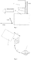
- an autonomously mobile backscatter detection apparatus 4 comprising a backscatter detection imaging apparatus 1 and a mobile platform 2.
- the backscatter detection imaging apparatus 1 is arranged on the mobile platform 2, and the mobile platform 2 is configured to move freely in a horizontal plane x-y.
- the mobile platform 2 provides the backscatter detection imaging apparatus 1 with electric power and/or the mobile platform 2 provides the backscatter detection imaging apparatus 1 with computing and processing capacity.
- the backscatter detection imaging apparatus 1 may be moved vertically along z-axis on the mobile platform 2 by a set of servo mechanisms.
- the backscatter detection imaging apparatus 1 may also be moved in a horizontal direction.
- the servo mechanism is an elevator 3 driven by a motor. It should be noted that the backscatter detection imaging apparatus may be configured to scan from bottom to top, from top to bottom, from left to right or from right to left, which is not intended to be limited herein.
- the mobile platform 2 may be a wheeled or tracked mobile platform, and a chassis of the mobile platform 2 has a slip configuration; in an example, the mobile platform 2 comprises two sets of servo mechanisms, and the mobile platform 2 is a two-wheeled or double-tracked mobile platform, wherein the two sets of servo mechanisms respectively drive two wheels or tracks of the mobile platform independently of each other.
- the mobile platform 2 is provided with a servo mechanism encoder for feeding back a distance by which the wheels or tracks travel.
- the mobile platform 2 is provided with a main control unit, for example, main control PLC, a pulse width modulation (PWM) control is performed on a movement of the backscatter detection imaging apparatus 1 by the main control unit of the mobile platform 2.
- PLC pulse width modulation
- Fig. 2 shows a scanning quality control process implemented by the autonomously mobile backscatter detection apparatus 4; as shown in Fig. 2 , the backscatter detection apparatus 4 travels along a given path T to the vicinity of an item 5 to be inspected, and performs a backscatter detection on the item 5 to be inspected.
- the autonomously mobile backscatter detection apparatus 4 autonomously moves the backscatter detection imaging apparatus 1 and/or the mobile platform 2 according to imaging quality, so as to adjust a distance L between the backscatter detection imaging apparatus 1 and the item 5 to be inspected.
- the autonomously mobile backscatter detection apparatus 4 autonomously moves the backscatter detection imaging apparatus 1 and/or the mobile platform 2 according to scattering angles at a receiving end of the backscatter detection imaging apparatus, so as to adjust a distance between the receiving end and the item 5 to be inspected.
- the autonomously mobile backscatter detection apparatus 4 may also be configured to autonomously adjust an irradiation intensity of the backscatter detection imaging apparatus 1 according to imaging quality, so as to ensure optimal imaging quality. After one item 5 to be inspected has been scanned, the mobile platform 2 is moved to the next item 5 to be inspected along the given path T, such that the backscatter detection imaging apparatus 1 sequentially scans a plurality of items 5 to be inspected.
- the autonomously mobile backscatter detection apparatus 4 may be configured to detect a gap between the items 5 to be inspected to determine a boundary of the item to be inspected, and configured to move the backscatter detection imaging apparatus 1 and/or the mobile platform 2 to be in an orientation close to a center of the item 5 to be inspected, which is determined according to the boundary.
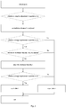
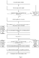
- Fig. 3 shows a flowchart of the scanning quality control process of the autonomously mobile backscatter detection apparatus 4.
- the backscatter detection apparatus 4 is initialized; after the initialization, it is determined whether an adaptive adjustment is required or not; if the adaptive adjustment is required, then an irradiation distance L between the backscatter detection imaging apparatus 1 and the item to be inspected 5 is firstly adjusted; after the adjustment of the irradiation distance L, it is determined whether an image requirement is satisfied or not; if the image requirement is not satisfied, then data returns to 0, otherwise it is determined whether an irradiation intensity I may be adjusted; if the irradiation intensity I cannot be adjusted, then the data returns to 0, otherwise the irradiation intensity I is adjusted; then it is determined whether the image requirement is satisfied or not; if the image requirement is not satisfied, then the data returns to 0, otherwise the data returns to 1; finally the control process is ended.
- the mobile platform 2 is provided with a laser ranging module (LSF), and position and distance information of points to be measured within a range of angles less than or equal to 270° in front of the mobile platform can be obtained by rotating the laser ranging module.
- the mobile platform 2 is provided with a memory for storing information necessary for an operation of the autonomously mobile backscatter detection apparatus 4.
- a backscatter detection method for the autonomously mobile backscatter detection apparatus 4 comprising steps of: determining a contour curve f(x) of a plurality of items 5 to be inspected by a trajectory tracking control algorithm in a Cartesian coordinate system; forming a trajectory curve t(x) of the mobile platform 2 according to the contour curve; moving the mobile platform 2 to be close to a first item 5 to be inspected along the trajectory curve and controlling the backscatter detection imaging apparatus 1 to scan the first item 5 to be inspected, under a control of a main control unit of the mobile platform 2; and continuing to move the mobile platform 2 along the trajectory curve, such that the backscatter detection imaging apparatus 1 sequentially scans the plurality of items 5 to be inspected.
- the step of determining the contour curve of the plurality of items 5 to be inspected comprises steps of: positioning the mobile platform 2 in place and rotating a laser ranging module of the mobile platform 2 to obtain position and distance information of the items 5 to be inspected within a range of angles less than or equal to 270° in front of the mobile platform 2, obtaining effective data points of the items to be inspected through filtering operation by a processor (optionally, an ARM processor), then calculating a contour curve function f(x) of the plurality of items 5 to be inspected in the Cartesian coordinate system by the processor based on the data points.
- the main control unit PLC generates a corresponding trajectory curve function t(x) based on the contour curve function, such that the point in the trajectory curve function t(x) is spaced apart from the corresponding point in the contour curve function f(x) by a distance d, where d is approximately equal to the distance between the backscatter detection imaging apparatus 1 and the item (box) 5 to be inspected.
- d is approximately equal to the distance between the backscatter detection imaging apparatus 1 and the item (box) 5 to be inspected.
- it further comprises a step of: detecting a gap between the items 5 to be inspected to distinguish different items 5 to be inspected and recording a position of the gap.
- An optimal scanning distance is calculated according to scattering angles and an area of the receiving end of the backscatter detection imaging apparatus 1 after detecting the gap between the items 5 to be inspected.
- the backscatter detection method further comprises a step of: moving the backscatter detection imaging apparatus 1 on the mobile platform 2 vertically or horizontally, so as to scan the items 5 to be inspected in an optimal imaging quality.
- the backscatter detection imaging apparatus 1 may be configured to scan from bottom to top, from top to bottom, from left to right or from right to left.
- the mobile platform 2 is provided with a main control unit, and a pulse width modulation control is performed on a movement of the backscatter detection imaging apparatus 1 by the main control unit of the mobile platform 2.
- the backscatter detection method further comprises a step of: moving the backscatter detection imaging apparatus 1 and/or the mobile platform 2 autonomously according to imaging quality, so as to adjust a distance between the backscatter detection imaging apparatus 1 and the item 5 to be inspected.
- it further comprises a step of: moving the backscatter detection imaging apparatus 1 and/or the mobile platform 2 autonomously according to scattering angles at a receiving end of the backscatter detection imaging apparatus, so as to adjust a distance between the receiving end and the item 5 to be inspected.
- the backscatter detection method further comprises a step of: adjusting an irradiation intensity of the backscatter detection imaging apparatus 1 autonomously according to imaging quality, so as to ensure optimal imaging quality.
- the backscatter detection method further comprises a step of: detecting a gap between the items to be inspected so as to determine a boundary of the item to be inspected, and moving the backscatter detection imaging apparatus and/or the mobile platform to be in an orientation close to a center of the item to be inspected, which is determined according to the boundary.
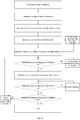
- the detection method is initialized; then a trajectory of edges of the box is processed to form a contour curve of a plurality of boxes; then following the trajectory, a travelling path of the mobile platform 2 is generated; the mobile platform 2 follows the path; then gaps between the boxes are detected over the whole path, and the information regarding all gaps between the boxes is recorded; the width of the box is calculated according to the information regarding the gaps between the boxes, and the mobile platform 2 is moved to a position close to the center of the box; then it is determined whether the center (scanning point) is reached or not; if not, then the mobile platform 2 is moved and adjusted according to the path and after that it is determined whether the center is reached or not; if so, then a lifting device (i.e., the elevator 3) is moved to implement the scanning of the box; after that, it is determined whether the scanning of the box is completed or not; if the scanning of the box is not completed, then the scanning of the box continues, otherwise it is determined whether the scanning of all the boxes is completed or not; if the scanning of all
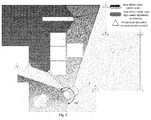
- a positioning method for the autonomously mobile backscatter detection apparatus 4 comprising steps of: moving the mobile platform 2 to a location where a plurality of feature points are capable of being detected, and collecting the plurality of feature points (in the embodiment shown in Fig.
- the feature points include virtual road sign points 1-8); stopping moving the mobile platform 2, observing the collected feature points, and determining whether the feature points are stationary or not, so as to select the stationary feature points; establishing a Cartesian coordinate system with a current position of a reference point on the mobile platform 2 as an origin point (0, 0), and a front direction of the mobile platform as a X-axis positive direction, and calculating coordinates of the plurality of feature points in the Cartesian coordinate system, and recording the coordinates (x1, y1), (x2, y2), (x3, y3) of the plurality of feature points; delimiting a first positioning area where three or more feature points are capable of being simultaneously observed by the mobile platform and a second positioning area excluding the first positioning area (as shown in Fig.
- the area where the virtual road sign cannot be used to implement positioning is the second positioning area); and determining a position of the mobile platform 2 by a three-point positioning algorithm when the mobile platform 2 is located in the first positioning area, and determining the position of the mobile platform 2 by an servo mechanism encoder of the mobile platform 2 when the mobile platform 2 is located in the second positioning area.
- the backscatter detection apparatus 4 in order to collect the feature points (generally wall corners, pillars or the like), the backscatter detection apparatus 4 (robot) is firstly autonomously moved to a proper location so as to cover a wide range of feature points; then 5-10 stationary feature points are selected; if the number of the selected stationary feature points is less than 5, then the positioning method controls to move the mobile platform 2 to a new location, and collect and select the feature points again.
- the observing area includes obstacles 6 and pillars 7.
- the backscatter detection apparatus 4 can recognize and record the virtual road sign points 1-8 as the feature points.
- the feature points may comprise wall corners, pillars or door frames.
- the step of determining the position of the mobile platform 2 by the three-point positioning algorithm comprises steps of: rotating a laser ranging module of the mobile platform 2 to measure distances (r1, r2, r3) between the mobile platform 2 and three respective feature points, and determining the position of the mobile platform 2 based on the distances and the recorded coordinates (x1, y1), (x2, y2), (x3, y3) of the three feature points.
- the step of determining the position of the mobile platform 2 by the servo mechanism encoder of the mobile platform 2 comprises a step of: feeding back a distance by which a wheel or a track travels through two servo motor encoders operated independently of each other, so as to calculate a position and an attitude angle of the mobile platform 2 by a main control unit of the mobile platform 2.
- the position determined by the three-point positioning algorithm is used to replace the position determined by the servo mechanism encoder to eliminate accumulative error, when the mobile platform 2 is located in the first positioning area.
- the system is started and initialized; then the laser ranging module (LSF) is started to determine whether the requirements for collecting feature points have been satisfied or not; if the requirements are not satisfied, then the mobile platform 2 is autonomously moved to a new location and the laser ranging module is restarted; if the requirements are satisfied, then a global coordinate system is initialized; the coordinates (x, y) (i.e., virtual road signs) of the feature points in this coordinate system are calculated; the virtual road signs and a program for the first positioning area are called, as shown in Fig.
- LSF laser ranging module
- the system is run to inquire whether the mobile platform 2 is running in the first positioning area or not; if not, then the servo mechanism encoder (a drive wheel encoder) is used to calculate positioning coordinates and attitude; if yes, then the three-point positioning program runs to implement positioning and determine the attitude according to two positioning coordinates; then the program is ended, without returning variables.
- the servo mechanism encoder a drive wheel encoder
Landscapes
- Physics & Mathematics (AREA)
- Life Sciences & Earth Sciences (AREA)
- Health & Medical Sciences (AREA)
- General Physics & Mathematics (AREA)
- Chemical & Material Sciences (AREA)
- Engineering & Computer Science (AREA)
- Geophysics (AREA)
- General Life Sciences & Earth Sciences (AREA)
- High Energy & Nuclear Physics (AREA)
- General Health & Medical Sciences (AREA)
- Pathology (AREA)
- Crystallography & Structural Chemistry (AREA)
- Analytical Chemistry (AREA)
- Biochemistry (AREA)
- Immunology (AREA)
- Biomedical Technology (AREA)
- Veterinary Medicine (AREA)
- Medical Informatics (AREA)
- Molecular Biology (AREA)
- Surgery (AREA)
- Animal Behavior & Ethology (AREA)
- Public Health (AREA)
- Heart & Thoracic Surgery (AREA)
- Robotics (AREA)
- Mechanical Engineering (AREA)
- Biophysics (AREA)
- Oral & Maxillofacial Surgery (AREA)
- Dentistry (AREA)
- Optical Radar Systems And Details Thereof (AREA)
- Control Of Position, Course, Altitude, Or Attitude Of Moving Bodies (AREA)
Applications Claiming Priority (1)
| Application Number | Priority Date | Filing Date | Title |
|---|---|---|---|
| CN201610634464.7A CN106066338B (zh) | 2016-08-04 | 2016-08-04 | 自主移动的背散射检测设备和方法及设备的定位方法 |
Publications (2)
| Publication Number | Publication Date |
|---|---|
| EP3279702A2 true EP3279702A2 (de) | 2018-02-07 |
| EP3279702A3 EP3279702A3 (de) | 2018-05-30 |
Family
ID=57206853
Family Applications (1)
| Application Number | Title | Priority Date | Filing Date |
|---|---|---|---|
| EP17173781.0A Withdrawn EP3279702A3 (de) | 2016-08-04 | 2017-05-31 | Vorrichtung und verfahren zur autonom mobilen rückstrahlungsdetektion und positionierungsverfahren für die vorrichtung |
Country Status (3)
| Country | Link |
|---|---|
| US (1) | US10634627B2 (de) |
| EP (1) | EP3279702A3 (de) |
| CN (1) | CN106066338B (de) |
Families Citing this family (5)
| Publication number | Priority date | Publication date | Assignee | Title |
|---|---|---|---|---|
| CN107553488B (zh) * | 2017-09-01 | 2019-03-08 | 北京信息职业技术学院 | 一种室内移动机器人测试系统和方法 |
| CN113805193B (zh) * | 2020-05-29 | 2025-01-24 | 清华大学 | 背散射机器人的防误触发方法、背散射机器人及路径规划方法 |
| CN111818273A (zh) * | 2020-08-04 | 2020-10-23 | 深圳市软筑信息技术有限公司 | 一种智能led补光系统 |
| CN115508386A (zh) * | 2022-09-26 | 2022-12-23 | 公安部第一研究所 | 一种背散射x射线物品安全检查设备图像解析度测试装置 |
| CN119000735B (zh) * | 2024-10-22 | 2025-02-07 | 昆山市建设工程质量检测中心有限公司 | 预制墙体内套筒装配端连接钢筋是否截断的无损检测方法 |
Family Cites Families (12)
| Publication number | Priority date | Publication date | Assignee | Title |
|---|---|---|---|---|
| US5181234B1 (en) * | 1990-08-06 | 2000-01-04 | Rapiscan Security Products Inc | X-ray backscatter detection system |
| US5936240A (en) * | 1996-01-30 | 1999-08-10 | The United States Of America As Represented By The United States Department Of Energy | Mobile autonomous robotic apparatus for radiologic characterization |
| JP3657854B2 (ja) * | 2000-05-10 | 2005-06-08 | 日本電信電話株式会社 | 遠隔地観測装置 |
| US8355818B2 (en) * | 2009-09-03 | 2013-01-15 | Battelle Energy Alliance, Llc | Robots, systems, and methods for hazard evaluation and visualization |
| US8027427B2 (en) * | 2009-08-31 | 2011-09-27 | Morpho Detection, Inc. | Systems and method for scanning a continuous stream of objects |
| US8917927B2 (en) * | 2010-08-17 | 2014-12-23 | Telesecurity Sciences, Inc. | Portable backscatter advanced imaging technology scanner with automated target recognition |
| US9055886B1 (en) * | 2011-01-05 | 2015-06-16 | Sandia Corporation | Automatic tool alignment in a backscatter x-ray scanning system |
| US8908831B2 (en) * | 2011-02-08 | 2014-12-09 | Rapiscan Systems, Inc. | Covert surveillance using multi-modality sensing |
| CN104133251B (zh) | 2014-07-04 | 2017-08-25 | 清华大学 | 移动式背散射成像安检设备及方法 |
| CN104062688A (zh) * | 2014-07-04 | 2014-09-24 | 同方威视技术股份有限公司 | 基于分布式辐射源的x射线背散射通道式车辆安检系统和方法 |
| GB2519241B (en) * | 2014-11-10 | 2019-09-04 | Epicuro Ltd | Security inspection robot |
| CN205898713U (zh) * | 2016-08-04 | 2017-01-18 | 同方威视技术股份有限公司 | 自主移动的背散射检测设备 |
-
2016
- 2016-08-04 CN CN201610634464.7A patent/CN106066338B/zh active Active
-
2017
- 2017-05-31 US US15/610,450 patent/US10634627B2/en active Active
- 2017-05-31 EP EP17173781.0A patent/EP3279702A3/de not_active Withdrawn
Non-Patent Citations (1)
| Title |
|---|
| None |
Also Published As
| Publication number | Publication date |
|---|---|
| US20180038809A1 (en) | 2018-02-08 |
| EP3279702A3 (de) | 2018-05-30 |
| US10634627B2 (en) | 2020-04-28 |
| CN106066338B (zh) | 2019-03-19 |
| CN106066338A (zh) | 2016-11-02 |
Similar Documents
| Publication | Publication Date | Title |
|---|---|---|
| EP3279702A2 (de) | Vorrichtung und verfahren zur autonom mobilen rückstrahlungsdetektion und positionierungsverfahren für die vorrichtung | |
| JP6850867B2 (ja) | 寸法閾値を超えて延在しているアイテムを検出する検出器を有する自動格納及び取得システム | |
| EP3290385B1 (de) | Anlegerkran mit behälterinspektionssystem | |
| JP4241651B2 (ja) | 移動装置 | |
| US11822043B2 (en) | Radiation inspection apparatus comprising a radiation inspection device and wheels and radiation inspection method | |
| JP4574609B2 (ja) | レーザーポインタを用いた天井クレーンによる搬送方法及び天井クレーンシステム | |
| KR101970747B1 (ko) | 크레인 코일 상하차 제어 시스템 | |
| CN107539191A (zh) | 包括操纵系统的车辆 | |
| KR20180052045A (ko) | 레이저 스캐너를 이용한 대상 물체의 실시간 동적 위치 추적이 가능한 3d 레이저 스캐너 시스템 | |
| EP3924794B1 (de) | Überprüfungssystem für autonome flugzeuge | |
| JP6187499B2 (ja) | 自律移動ロボットの自己位置推定方法、自律移動ロボット、及び自己位置推定用ランドマーク | |
| JP2002211747A (ja) | コンベヤ装置 | |
| KR102438943B1 (ko) | 기준 마커를 포함하는 컨테이너 크레인 | |
| CN114111627A (zh) | 基于激光跟踪仪的扫描系统和扫描方法 | |
| CN114967673A (zh) | 移动体的控制方法、移动体以及计算机可读取的存储介质 | |
| CN116940519A (zh) | 输送可否判定装置、测距装置、输送单元、输送可否判定方法、输送可否判定程序 | |
| CN205898713U (zh) | 自主移动的背散射检测设备 | |
| WO2023192331A1 (en) | Localization of horizontal infrastructure using point clouds | |
| JP7511504B2 (ja) | 移動体、移動制御システム、移動体の制御方法及びプログラム | |
| KR102564663B1 (ko) | 무인 반송 차량의 위치 인식 장치 및 방법 | |
| Fareh et al. | An integrated vision-guided robotic system for rapid vehicle inspection | |
| KR101010781B1 (ko) | 비접촉 환경 계측 장치, 방법 및 컴퓨터 프로그램이 기록된기록매체 | |
| JP7283152B2 (ja) | 自律移動装置、プログラムおよび自律移動装置の操舵方法 | |
| JP2625222B2 (ja) | コイル位置検出装置 | |
| JP7816296B2 (ja) | ロボットシステム |
Legal Events
| Date | Code | Title | Description |
|---|---|---|---|
| PUAI | Public reference made under article 153(3) epc to a published international application that has entered the european phase |
Free format text: ORIGINAL CODE: 0009012 |
|
| STAA | Information on the status of an ep patent application or granted ep patent |
Free format text: STATUS: THE APPLICATION HAS BEEN PUBLISHED |
|
| AK | Designated contracting states |
Kind code of ref document: A2 Designated state(s): AL AT BE BG CH CY CZ DE DK EE ES FI FR GB GR HR HU IE IS IT LI LT LU LV MC MK MT NL NO PL PT RO RS SE SI SK SM TR |
|
| AX | Request for extension of the european patent |
Extension state: BA ME |
|
| PUAL | Search report despatched |
Free format text: ORIGINAL CODE: 0009013 |
|
| AK | Designated contracting states |
Kind code of ref document: A3 Designated state(s): AL AT BE BG CH CY CZ DE DK EE ES FI FR GB GR HR HU IE IS IT LI LT LU LV MC MK MT NL NO PL PT RO RS SE SI SK SM TR |
|
| AX | Request for extension of the european patent |
Extension state: BA ME |
|
| RIC1 | Information provided on ipc code assigned before grant |
Ipc: G01V 5/00 20060101AFI20180423BHEP |
|
| STAA | Information on the status of an ep patent application or granted ep patent |
Free format text: STATUS: REQUEST FOR EXAMINATION WAS MADE |
|
| 17P | Request for examination filed |
Effective date: 20180625 |
|
| RBV | Designated contracting states (corrected) |
Designated state(s): AL AT BE BG CH CY CZ DE DK EE ES FI FR GB GR HR HU IE IS IT LI LT LU LV MC MK MT NL NO PL PT RO RS SE SI SK SM TR |
|
| STAA | Information on the status of an ep patent application or granted ep patent |
Free format text: STATUS: EXAMINATION IS IN PROGRESS |
|
| 17Q | First examination report despatched |
Effective date: 20211105 |
|
| STAA | Information on the status of an ep patent application or granted ep patent |
Free format text: STATUS: THE APPLICATION IS DEEMED TO BE WITHDRAWN |
|
| 18D | Application deemed to be withdrawn |
Effective date: 20220316 |