EP3279534A1 - Bouton rotatif comprenant un accumulateur de force mobile - Google Patents
Bouton rotatif comprenant un accumulateur de force mobile Download PDFInfo
- Publication number
- EP3279534A1 EP3279534A1 EP17020207.1A EP17020207A EP3279534A1 EP 3279534 A1 EP3279534 A1 EP 3279534A1 EP 17020207 A EP17020207 A EP 17020207A EP 3279534 A1 EP3279534 A1 EP 3279534A1
- Authority
- EP
- European Patent Office
- Prior art keywords
- control unit
- unit
- drive
- adjustment
- spring
- Prior art date
- Legal status (The legal status is an assumption and is not a legal conclusion. Google has not performed a legal analysis and makes no representation as to the accuracy of the status listed.)
- Granted
Links
Images


Classifications
-
- F—MECHANICAL ENGINEERING; LIGHTING; HEATING; WEAPONS; BLASTING
- F01—MACHINES OR ENGINES IN GENERAL; ENGINE PLANTS IN GENERAL; STEAM ENGINES
- F01P—COOLING OF MACHINES OR ENGINES IN GENERAL; COOLING OF INTERNAL-COMBUSTION ENGINES
- F01P7/00—Controlling of coolant flow
- F01P7/14—Controlling of coolant flow the coolant being liquid
- F01P7/16—Controlling of coolant flow the coolant being liquid by thermostatic control
-
- F—MECHANICAL ENGINEERING; LIGHTING; HEATING; WEAPONS; BLASTING
- F16—ENGINEERING ELEMENTS AND UNITS; GENERAL MEASURES FOR PRODUCING AND MAINTAINING EFFECTIVE FUNCTIONING OF MACHINES OR INSTALLATIONS; THERMAL INSULATION IN GENERAL
- F16K—VALVES; TAPS; COCKS; ACTUATING-FLOATS; DEVICES FOR VENTING OR AERATING
- F16K31/00—Actuating devices; Operating means; Releasing devices
- F16K31/02—Actuating devices; Operating means; Releasing devices electric; magnetic
- F16K31/04—Actuating devices; Operating means; Releasing devices electric; magnetic using a motor
- F16K31/041—Actuating devices; Operating means; Releasing devices electric; magnetic using a motor for rotating valves
- F16K31/043—Actuating devices; Operating means; Releasing devices electric; magnetic using a motor for rotating valves characterised by mechanical means between the motor and the valve, e.g. lost motion means reducing backlash, clutches, brakes or return means
-
- F—MECHANICAL ENGINEERING; LIGHTING; HEATING; WEAPONS; BLASTING
- F16—ENGINEERING ELEMENTS AND UNITS; GENERAL MEASURES FOR PRODUCING AND MAINTAINING EFFECTIVE FUNCTIONING OF MACHINES OR INSTALLATIONS; THERMAL INSULATION IN GENERAL
- F16K—VALVES; TAPS; COCKS; ACTUATING-FLOATS; DEVICES FOR VENTING OR AERATING
- F16K31/00—Actuating devices; Operating means; Releasing devices
- F16K31/02—Actuating devices; Operating means; Releasing devices electric; magnetic
- F16K31/04—Actuating devices; Operating means; Releasing devices electric; magnetic using a motor
- F16K31/047—Actuating devices; Operating means; Releasing devices electric; magnetic using a motor characterised by mechanical means between the motor and the valve, e.g. lost motion means reducing backlash, clutches, brakes or return means
-
- F—MECHANICAL ENGINEERING; LIGHTING; HEATING; WEAPONS; BLASTING
- F16—ENGINEERING ELEMENTS AND UNITS; GENERAL MEASURES FOR PRODUCING AND MAINTAINING EFFECTIVE FUNCTIONING OF MACHINES OR INSTALLATIONS; THERMAL INSULATION IN GENERAL
- F16K—VALVES; TAPS; COCKS; ACTUATING-FLOATS; DEVICES FOR VENTING OR AERATING
- F16K31/00—Actuating devices; Operating means; Releasing devices
- F16K31/02—Actuating devices; Operating means; Releasing devices electric; magnetic
- F16K31/06—Actuating devices; Operating means; Releasing devices electric; magnetic using a magnet, e.g. diaphragm valves, cutting off by means of a liquid
- F16K31/0675—Electromagnet aspects, e.g. electric supply therefor
-
- F—MECHANICAL ENGINEERING; LIGHTING; HEATING; WEAPONS; BLASTING
- F16—ENGINEERING ELEMENTS AND UNITS; GENERAL MEASURES FOR PRODUCING AND MAINTAINING EFFECTIVE FUNCTIONING OF MACHINES OR INSTALLATIONS; THERMAL INSULATION IN GENERAL
- F16K—VALVES; TAPS; COCKS; ACTUATING-FLOATS; DEVICES FOR VENTING OR AERATING
- F16K31/00—Actuating devices; Operating means; Releasing devices
- F16K31/44—Mechanical actuating means
-
- G—PHYSICS
- G05—CONTROLLING; REGULATING
- G05G—CONTROL DEVICES OR SYSTEMS INSOFAR AS CHARACTERISED BY MECHANICAL FEATURES ONLY
- G05G15/00—Mechanical devices for initiating a movement automatically due to a specific cause
-
- G—PHYSICS
- G05—CONTROLLING; REGULATING
- G05G—CONTROL DEVICES OR SYSTEMS INSOFAR AS CHARACTERISED BY MECHANICAL FEATURES ONLY
- G05G23/00—Means for ensuring the correct positioning of parts of control mechanisms, e.g. for taking-up play
-
- G—PHYSICS
- G05—CONTROLLING; REGULATING
- G05G—CONTROL DEVICES OR SYSTEMS INSOFAR AS CHARACTERISED BY MECHANICAL FEATURES ONLY
- G05G5/00—Means for preventing, limiting or returning the movements of parts of a control mechanism, e.g. locking controlling member
- G05G5/05—Means for returning or tending to return controlling members to an inoperative or neutral position, e.g. by providing return springs or resilient end-stops
-
- F—MECHANICAL ENGINEERING; LIGHTING; HEATING; WEAPONS; BLASTING
- F01—MACHINES OR ENGINES IN GENERAL; ENGINE PLANTS IN GENERAL; STEAM ENGINES
- F01P—COOLING OF MACHINES OR ENGINES IN GENERAL; COOLING OF INTERNAL-COMBUSTION ENGINES
- F01P7/00—Controlling of coolant flow
- F01P7/14—Controlling of coolant flow the coolant being liquid
- F01P2007/146—Controlling of coolant flow the coolant being liquid using valves
-
- F—MECHANICAL ENGINEERING; LIGHTING; HEATING; WEAPONS; BLASTING
- F01—MACHINES OR ENGINES IN GENERAL; ENGINE PLANTS IN GENERAL; STEAM ENGINES
- F01P—COOLING OF MACHINES OR ENGINES IN GENERAL; COOLING OF INTERNAL-COMBUSTION ENGINES
- F01P2031/00—Fail safe
Definitions
- the present invention relates to a controller and a method for operating an electronically controlled regulator, which has a fail-safe function by means of an unlockable coil spring, which is carried in the tensioned state.
- Electronically controlled rotary regulators are used, for example, to control a cooling circuit in a vehicle engine.
- the rotary knob may comprise a rotary valve, which may be connected on the one hand via an axis with a valve which controls a coolant flow, or else on the other hand, the coolant flow can influence directly.
- the coolant flow By controlling the coolant flow, the vehicle engine is maintained at a desired temperature.
- the rotary knob must therefore have a so-called fail-safe function, which ensures that the rotary valve assumes a safety position in the event of a malfunction and ensures the coolant flow.
- the following solutions are known from the prior art.
- a rotary valve is described with at least one return element, wherein the return element against a spring rotatable and durable via a locking device. After releasing the locking device a driving means for rotating the rotary valve is provided by the return element.
- a valve for use in coolant flows wherein a fail-safe disc is provided with a spring.
- the fail-safe disc can be locked by biasing the spring in a valve body, wherein the valve body operates in normal operation, regardless of spring forces.
- the connection between the fail-safe disc and the valve housing is released and the valve body is rotated by the bias of the spring in an open position.
- FIG. 2 developed as a linear replacement diagram shown concept.
- the electric motor displaces the rotary valve via an adjusting unit coupled thereto. In case of failure, this coupling is released and further attached to the rotary valve return spring moves it to the safety position. Since a moment of inertia and friction torque of the drive with electric motor need not be overcome, the moment of force of the return spring can be less than in the FIG. 1 associated procedures are designed. However, in turn must constantly worked against the return spring and therefore the electric motor is energized permanently.
- FIG. 3 developed as a linear replacement diagram shown method.
- the return spring is first biased and locked in an initialization process.
- the return spring can be unlocked and acting on the rotary valve such that it is moved to the safety position.
- a disadvantage of this method is that when triggering the return spring in case of failure, a very high return pulse acts on the applied rotary valve together with connected drive.
- a conceivable cushioning damper element leads to a higher weight and / or cost factor.
- the electric motor does not usually work against the return spring and can therefore be energized less, but it must be sufficiently large, in order to overcome during the initialization of the moment of force of the return spring and the friction torque of the rotary valve.
- the regulator comprises at least one control unit, an adjustment unit, a drive unit which is configured to adjust the adjustment unit, and a locking and unlockable force storage.
- the control unit and the adjusting unit are in indirect contact with each other via the energy accumulator.
- the control unit is displaceable by the adjusting unit with locked, charged energy storage with entrainment of the force accumulator within an adjustment range.
- the control unit Upon unlocking of the charged force accumulator, the control unit is automatically brought into a safety position by an at least partially occurring discharge of the energy accumulator, regardless of the adjustment.
- the energy storage is a spring, in particular a coil spring.
- a charged energy storage then corresponds to a prestressed spring or a preloaded spiral spring.
- spring and “return spring” are used interchangeably.
- a spiral spring is a special expression of a spring or a return spring.
- Coupled and “coupling” are also used synonymously below.
- the controller according to the invention is designed as a knob, wherein the control unit is realized as a rotary valve.
- the drive unit is further configured to charge the energy storage, i. in the case of a spring, to bias this accordingly.
- the drive unit is a self-locking drive, in particular a worm drive.
- the drive unit comprises an electric motor.
- the controller according to the invention comprises in a further embodiment, a locking and unlocking mechanism which is configured to lock the power storage, if necessary, or in particular to automatically unlock in case of an error.
- This locking and unlocking mechanism is realized in an embodiment by an electromagnetic coupling between the control unit and adjustment.
- the rotary valve and the adjusting unit ie the control unit and the adjusting unit, are positively and / or non-positively connected with each other.
- the adhesion can be done via an electromagnetic coupling.
- the rotary valve, ie the control unit can be moved in this state in a total provided adjustment. In this case, only a friction torque of the rotary valve, ie the control unit must be overcome. In the case of a fault, ie in an error case, for example.
- the connection between the rotary valve, that is solved between the control unit and adjustment, ie the energy storage is unlocked.
- the energy storage is at least partially discharged, that is, energy is released.
- the energy released by a force acting on the rotary valve restoring or torque of the spring is transmitted to the rotary valve, ie the control unit.
- the rotary valve, ie the control unit moves the rotary valve, ie the control unit in a safety position, ie usually in an initial position.
- the torques to be overcome do not add up, but divide into the preload torque and the control torque.
- the rotary valve When using the rotary knob according to the invention in a coolant circuit of a vehicle using a self-locking drive the rotary valve can be moved back with the vehicle in its initial position and the return spring must not be re-biased at a restart of the vehicle again. The bias remains. All that needs to be done is a connection between the rotary valve and the adjusting unit via the prestressed spring.
- the present invention further relates to a method for operating an electronically controlled controller with a controllable by an electronically driven adjustment control unit, in which a fail-safe function is realized by means of a lockable and unlockable energy storage, which in a normal operation in a charged and locked State produces an active contact between adjusting and control unit and is carried along with adjustment of the control unit with the control unit, and which unlocks in an error case and is thus at least partially discharged, whereby the control unit is automatically brought independently of the adjustment in a safety position.
- the energy storage is performed by a spring, in particular a spiral spring.
- the controller is selected as a rotary control with a rotary valve as a control unit.
- the adjustment unit to be charged and the energy accumulator to be charged by an electromagnetic drive comprising an electric motor.
- Both the method according to the invention and the controller according to the invention can be used for other purposes, in addition to use in a coolant control, in particular in a vehicle, such as.
- a coolant control in particular in a vehicle, such as.
- a vehicle such as.
- an actuator with a necessary accident protection in both linear and rotatory arrangement in an actuator with a necessary accident protection in both linear and rotatory arrangement.
- FIGS. 1 to 3 show exemplarily linear replacement diagrams for known from the prior art solutions to a rotary knob, which has a fail-safe function, ie assuming a safety position in the event of a fault.
- FIGS. 4 and 5 the functional principle of an embodiment of the rotary knob according to the invention is shown in the execution of an embodiment of the method according to the invention in a plan view.
- FIG. 6 shows that to the FIGS. 4 and 5 associated linear replacement diagram.
- FIGS. 7 and 8th represent further embodiments of the rotary knob according to the invention as a respective sectional view.
- FIGS. 9 and 10 show characteristics of an embodiment of the method according to the invention, also in comparison with known from the prior art method for a torque as a function of an adjustment angle.
- FIG. 11 shows in the views 11a, 11b and 11c by way of example a possible implementation of a construction for an embodiment of the rotary knob according to the invention, which can perform an embodiment of the method according to the invention.
- FIG. 1 shows two operating states 101, 102, ie, a starting position 101 and a rule case 102, a rotary control having a rotary valve 122, which is displaced by a drive 120 within an adjustment range 130 or can be moved.
- a fail-safe function is implemented by a simple return spring 110,112. With a relaxed return spring 110, the starting position 101, which also represents the safety position, in which a coolant flow is ensured formed.
- the rotary valve 122 releases the entire adjustment range 130. As a rule, the rotary valve 122 is displaced up to a complete closure of the adjustment area 130.
- the tensioned return spring 112 brings in case of failure, which could be caused for example by a failure of the drive 120, the rotary valve 122 back to the starting position 101, but this must have a high moment of force, since the entire knob with rotary valve 122 and toothed with the rotary valve 122 Drive 120 must be moved.
- 102 is constantly working against the high torque of the return spring 112 by the drive 120, an electric motor acting on the drive 120 must be dimensioned very large. In addition, this requires a permanent energization of the electric motor.
- FIG. 2 a possibility is shown, brought in case of failure, the rotary valve solved by its drive in the safety position.
- a drive 220 displaces the rotary valve 222 via an adjusting unit 224, which are connected to one another by means of a locked coupling 226.
- the rotary valve 222 releases an entire adjustment range 230.
- the return spring 210 is in the relaxed state.
- the rotary valve 222 is displaced within the adjustment range 230 as far as a maximum tensioned return spring 212.
- the coupling is released as indicated by reference numeral 228 and secured to the rotary valve and through the released coupling Relaxing return spring 214 moves it into a so-called "fail-safe" area 232. Since not an inertial moment and friction torque of the drive 220 and the electric motor acting on it must be overcome, the moment of force of the return spring can be less than in the basis of FIG. 1 be configured described method. However, it must also be constantly worked against the return spring and therefore the electric motor to be permanently energized.
- the rotary valve 322 is displaced by the drive 320 from the starting position 301 by a pretensioning region 332.
- the initially relaxed return spring 310 is hereby set in a tensioned state 312, and held in this by a locking operation 302 by means of a hinged latch 340, as indicated by a bent arrow.
- the rotary slide 322 can now be displaced within the adjustment region 330 as a rule without applying the return spring 314 held by the latched latch 342.
- the return spring 314 can be unlocked and act on the rotary valve 322 such that it is moved to the safety position corresponding to the starting position 301.
- a disadvantage of this method is that when triggering the return spring in case of failure, a very high return pulse acts on the impinged rotary valve 322 together with connected drive 320.
- FIG. 4 shows a plan view schematically a rotary knob, which can realize an embodiment of the method according to the invention.
- a rotary valve 422 forms with an outer spring holder 424 a first composite "rotary valve” and is, not visible in this illustration, flanged to a valve for controlling a coolant flow.
- the valve is maximally open when the outer spring retainer 424 is in a position 404, while it is closed when the rotary valve 422 is rotated clockwise by an angle of 135 degrees to the position 408. Between these two positions 404 and 408 is the adjustment.
- a coil containing brake body 406 For biasing a formed as a coil spring return spring 412, which serves as a force storage, a coil containing brake body 406 passes through a biasing region 402 between the maximum coolant flow important security position 404 and a locking position 410, in which he counterclockwise at an angle of 135 degrees is turned. The brake body 406 is acted upon by a drive 414. If the brake body 406 is in the locking position 410, an electromagnetic field, which is generated by energizing the coil contained in the brake body 406, acts on the brake bar 416 and deflects it in this way indicates that the brake is locked to the rotary valve 422.
- the brake body 406, the latch formed as a brake 416, designed as an inner spring support pivot axis 418, and an opening 420 form a second composite "adjustment / latch".
- An opening angle of 135 degrees selected in the illustration merely serves to illustrate the method according to the invention. In general, other opening angles, such as 90 Degree or 180 degrees, conceivable, but coupled to the adjustment range resulting from the valve positions between closure and maximum opening.
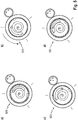
- FIG. 5 shows the different operating states of the in FIG. 4 individually shown on the rotary knob.
- the first composite "rotary valve” is not locked with the second composite "adjusting unit / latch".
- the outer spring retainer 424 is located at a left abutment point of the opening 420.
- the second "adjuster / latch" assembly is rotated 135 degrees counterclockwise by the drive 414 to the lock position 410.
- the outer spring holder 424 is now located at a right stop point of the opening 420.
- an electromagnetic field which is generated by energizing the coil contained in the brake body 406 coil, acts on the formed as a brake latch 416 and deflects it such that the Brake with the rotary valve 422 is locked flush.
- the two interlocked assemblies "rotary valve” and “adjusting unit / bolt” are now acted upon jointly by the drive 414.
- the electromagnetic field generated by the coil, and thus the lock remain.
- the two assemblies are acted upon by the drive 414 in such a way that the outer spring holder located in the "rotary valve” composite between the positions 404, corresponding to a maximum valve opening, and 408, corresponding to a valve closure, is within the adjustment range.
- the fail-safe function of the method according to the invention is triggered.
- the energization of the electromagnetic field generating coil is turned off, whereby the trained as a brake latch 416 of the rotary valve 422 dissolves, causing the two composites "rotary valve” and "adjusting / bar” can rotate separately.
- the biased return spring 412 discharges by deflection of the outer spring retainer 424, whereby the first composite "rotary valve", in the position 404, which corresponds to the maximum valve opening and in case of accident the Security position is brought.
- a released by the opening 420 further displacement of the composite "rotary valve” counterclockwise is excluded by the restriction of the adjustment.
- FIG. 6 the operating conditions are off FIG. 5 shown as a linear replacement diagram.
- the rotary valve 622 releases the entire adjustment range 630, which corresponds to a maximum coolant flow.
- an open latch 644 On one of a drive 620 acted upon adjusting 624 or on the rotary valve 622 is an open latch 644.
- Rotary valve 622 and adjusting unit 624 are connected to each other via a return spring 610. Depending on the position of the return spring this is in the context of FIG. 6 hereinafter referred to by the reference numerals 610 (initial position - relaxed state), 612 (biased state), 614 (preloaded and locked state) and 616 (unlocked and relaxing state).
- the relaxing return spring 616 discharges on the rotary slide 622 and returns it to the starting position, which corresponds to the safety position with maximum coolant flow.
- FIG. 7 schematically shows a sectional view of a possible first construction of a rotary controller 700 according to the invention for carrying out an embodiment of the method according to the invention.
- a drive 701 acts on the brake body 706, which carries a designed as a brake 703 latch with it. It is also on the Brake body 706 designed as an inner spring retainer axis of rotation 707 available.
- a coil 702 On a rotary valve 705 is located in this design state, a coil 702, the electromagnetic field can bring the brakes 703 in contact with the rotary valve 705.
- it contains an outer spring holder 708 for a return spring 704, in particular a spiral spring or leg spring.
- FIG. 8 schematically shows a sectional view of a possible second construction of a rotary control 800 according to the invention for carrying out an embodiment of the method according to the invention.
- a drive 801 acts on a brake body 806 at which a coil 802 is located at this design stage. Its electromagnetic field is designed so that it exerts on a rotary valve 805 an attractive effect with a direction toward the brake body 806.
- At contact points 803 may be a brake pad.
- a return spring 804 in particular a spiral spring or leg spring, is anchored with a spring holder 807 on the brake body and with a spring holder 808 on the rotary valve.
- FIG. 9 shows ranges of occurring torques 904 when carrying out an embodiment of the method according to the invention as a function of a displacement angle 902.
- the ordinate therefore shows the torque 904 and the abscissa represents the displacement angle 902.
- a spring characteristic 910 of a return spring to be provided as a force accumulator is used.
- FIG. 4 described composites "rotary valve” and “adjustment” are spent.
- this includes an area 908 up to typically 1.4 Nm, shown in the negative portion of the torque axis 904.
- FIG. 10 represents the occurring torques of the different concepts FIGS. 1 . 2 and 3 towards the regulator according to the invention.
- Applied to the top is a so-called nominal torque 1004 normalized to the highest torque as a function of the adjustment angle in degrees 1002.
- a drive used in the respective concept must at least overcome the occurring torque to fulfill its function.
- the torque occurring during pretensioning in the case of the regulator according to the invention is shown in a pretensioning region 1008.
- the torques which normally occur in the regulator according to the invention for overcoming the frictional forces 1020 form the working region without acting on the restoring spring 1010, which has quantitatively lower torques than the pretensioning region 1008.
- the in FIG. 3 illustrated method 1018 as long as the return spring is locked.
- FIG. 11 is a possible implementation of a construction for an embodiment of the rotary knob according to the invention, which can perform an embodiment of the method according to the invention shown.
- FIG. 11a illustrates this as an exploded view, a worm wheel 1102, a worm wheel 1104, a motor 1106, a Brake body 1108, brake shoes 1110, a brake spring 1112, a return spring 1114, a magnet 1116, a magnetic body 1120 with a retaining ring 1118, a motor housing 1122 and a Z-valve 1124 includes.
- FIG. 11b the drive and the adjustment unit together with the control unit. Inserted in the motor housing shows this FIG. 11c ,
Applications Claiming Priority (1)
| Application Number | Priority Date | Filing Date | Title |
|---|---|---|---|
| DE102016114492.4A DE102016114492A1 (de) | 2016-08-04 | 2016-08-04 | Drehregler mit mitbewegbarem Kraftspeicher |
Publications (2)
| Publication Number | Publication Date |
|---|---|
| EP3279534A1 true EP3279534A1 (fr) | 2018-02-07 |
| EP3279534B1 EP3279534B1 (fr) | 2020-01-29 |
Family
ID=58714873
Family Applications (1)
| Application Number | Title | Priority Date | Filing Date |
|---|---|---|---|
| EP17020207.1A Active EP3279534B1 (fr) | 2016-08-04 | 2017-05-12 | Bouton rotatif comprenant un accumulateur de force mobile |
Country Status (6)
| Country | Link |
|---|---|
| US (1) | US10570804B2 (fr) |
| EP (1) | EP3279534B1 (fr) |
| JP (1) | JP6500058B2 (fr) |
| KR (1) | KR101993979B1 (fr) |
| CN (1) | CN107687364B (fr) |
| DE (1) | DE102016114492A1 (fr) |
Cited By (1)
| Publication number | Priority date | Publication date | Assignee | Title |
|---|---|---|---|---|
| EP3597973A1 (fr) * | 2018-07-20 | 2020-01-22 | Siemens Schweiz AG | Élément de transmission ainsi que mécanisme de réglage à ressort de réinitialisation et à dispositif d'arrêt de transmission à verrouillage automatique |
Families Citing this family (1)
| Publication number | Priority date | Publication date | Assignee | Title |
|---|---|---|---|---|
| GB2582575B (en) * | 2019-03-25 | 2023-05-03 | Rotork Controls | Failsafe module |
Citations (10)
| Publication number | Priority date | Publication date | Assignee | Title |
|---|---|---|---|---|
| EP1035307A1 (fr) | 1998-04-07 | 2000-09-13 | Nippon Thermostat Co., Ltd. | Dispositif de commande de refroidissement pour moteur a combustion interne |
| EP1085181A2 (fr) | 1999-09-16 | 2001-03-21 | Eaton Corporation | Commande électrique d'une servo-soupape de liquide de refroidissement d'un moteur |
| DE10243778A1 (de) | 2002-09-20 | 2004-03-25 | Siemens Ag | Stelleinrichtung |
| DE10319882A1 (de) * | 2003-05-03 | 2004-11-18 | Daimlerchrysler Ag | Leistungssteller mit Fail-Safe-Vorrichtung |
| DE102006050217A1 (de) * | 2006-10-25 | 2008-05-08 | Hella Kgaa Hueck & Co. | Elektrischer Stellantrieb |
| DE102008030769B4 (de) | 2008-06-28 | 2013-05-29 | Audi Ag | Drehschieber, elektromechanische Baugruppe sowie Verfahren zum Betreiben |
| DE102012208652B3 (de) | 2012-05-23 | 2013-09-19 | Magna Powertrain Ag & Co. Kg | Ventil |
| US20140097366A1 (en) * | 2011-04-15 | 2014-04-10 | Uwe Klippert | Actuating drive of an air passage device |
| DE102014204485B3 (de) * | 2014-03-11 | 2015-02-12 | Magna Powertrain Ag & Co. Kg | Ventil mit Fail-Safe-Mechanismus |
| DE102013223907A1 (de) * | 2013-11-22 | 2015-06-11 | Volkswagen Aktiengesellschaft | Stellmittel für einen Kühlmittelkreislauf sowie ein mit einem solchen Stellmittel ausgestattetes Kraftfahrzeug |
Family Cites Families (12)
| Publication number | Priority date | Publication date | Assignee | Title |
|---|---|---|---|---|
| US2904956A (en) * | 1955-03-28 | 1959-09-22 | Mcevoy Co | Actuating device |
| CA852063A (en) * | 1968-12-11 | 1970-09-22 | Canadian Westinghouse Company Limited | Modified butterfly trip valve |
| US3679852A (en) * | 1970-03-27 | 1972-07-25 | Meidensha Electric Mfg Co Ltd | Spring operated making driving mechanism for circuit breaking and switching device |
| US3808895A (en) * | 1973-02-09 | 1974-05-07 | J Fitzwater | Electric fail-safe actuator |
| US4619151A (en) * | 1985-04-19 | 1986-10-28 | Rockwell International Corporation | Two speed axle shift actuator |
| JP2690977B2 (ja) * | 1988-03-18 | 1997-12-17 | 株式会社日立製作所 | 内燃機関用電子制御式スロットルバルブ |
| US6915958B2 (en) * | 2002-05-22 | 2005-07-12 | Tesma International Inc. | Linear proportional valve |
| US20060238039A1 (en) * | 2005-04-06 | 2006-10-26 | Parker-Hannifin Corporation | Step motor valve assembly with fail-safe feature |
| JP2012247008A (ja) * | 2011-05-27 | 2012-12-13 | Keihin Corp | 弁装置 |
| KR101417221B1 (ko) * | 2011-12-01 | 2014-08-06 | 현대자동차주식회사 | 연료전지스택 냉각계 안정성 확보장치 |
| GB2514374A (en) * | 2013-05-21 | 2014-11-26 | Johnson Electric Sa | Electrically operated valve assembly |
| EP3014152B1 (fr) * | 2013-06-25 | 2017-05-03 | MAGNA Powertrain GmbH & Co KG | Soupape comportant un mécanisme à sûreté intégrée |
-
2016
- 2016-08-04 DE DE102016114492.4A patent/DE102016114492A1/de active Pending
-
2017
- 2017-05-12 EP EP17020207.1A patent/EP3279534B1/fr active Active
- 2017-07-31 JP JP2017147374A patent/JP6500058B2/ja active Active
- 2017-08-02 US US15/666,735 patent/US10570804B2/en active Active
- 2017-08-02 CN CN201710650513.0A patent/CN107687364B/zh active Active
- 2017-08-04 KR KR1020170098965A patent/KR101993979B1/ko active IP Right Grant
Patent Citations (10)
| Publication number | Priority date | Publication date | Assignee | Title |
|---|---|---|---|---|
| EP1035307A1 (fr) | 1998-04-07 | 2000-09-13 | Nippon Thermostat Co., Ltd. | Dispositif de commande de refroidissement pour moteur a combustion interne |
| EP1085181A2 (fr) | 1999-09-16 | 2001-03-21 | Eaton Corporation | Commande électrique d'une servo-soupape de liquide de refroidissement d'un moteur |
| DE10243778A1 (de) | 2002-09-20 | 2004-03-25 | Siemens Ag | Stelleinrichtung |
| DE10319882A1 (de) * | 2003-05-03 | 2004-11-18 | Daimlerchrysler Ag | Leistungssteller mit Fail-Safe-Vorrichtung |
| DE102006050217A1 (de) * | 2006-10-25 | 2008-05-08 | Hella Kgaa Hueck & Co. | Elektrischer Stellantrieb |
| DE102008030769B4 (de) | 2008-06-28 | 2013-05-29 | Audi Ag | Drehschieber, elektromechanische Baugruppe sowie Verfahren zum Betreiben |
| US20140097366A1 (en) * | 2011-04-15 | 2014-04-10 | Uwe Klippert | Actuating drive of an air passage device |
| DE102012208652B3 (de) | 2012-05-23 | 2013-09-19 | Magna Powertrain Ag & Co. Kg | Ventil |
| DE102013223907A1 (de) * | 2013-11-22 | 2015-06-11 | Volkswagen Aktiengesellschaft | Stellmittel für einen Kühlmittelkreislauf sowie ein mit einem solchen Stellmittel ausgestattetes Kraftfahrzeug |
| DE102014204485B3 (de) * | 2014-03-11 | 2015-02-12 | Magna Powertrain Ag & Co. Kg | Ventil mit Fail-Safe-Mechanismus |
Cited By (2)
| Publication number | Priority date | Publication date | Assignee | Title |
|---|---|---|---|---|
| EP3597973A1 (fr) * | 2018-07-20 | 2020-01-22 | Siemens Schweiz AG | Élément de transmission ainsi que mécanisme de réglage à ressort de réinitialisation et à dispositif d'arrêt de transmission à verrouillage automatique |
| US11144083B2 (en) | 2018-07-20 | 2021-10-12 | Siemens Schweiz Ag | Transmission element and actuating drive with a return spring and with a self-unlocking gear lock |
Also Published As
| Publication number | Publication date |
|---|---|
| US20180038266A1 (en) | 2018-02-08 |
| JP2018040346A (ja) | 2018-03-15 |
| DE102016114492A1 (de) | 2018-02-08 |
| KR101993979B1 (ko) | 2019-06-27 |
| KR20180016315A (ko) | 2018-02-14 |
| JP6500058B2 (ja) | 2019-04-10 |
| CN107687364B (zh) | 2020-10-09 |
| US10570804B2 (en) | 2020-02-25 |
| EP3279534B1 (fr) | 2020-01-29 |
| CN107687364A (zh) | 2018-02-13 |
Similar Documents
| Publication | Publication Date | Title |
|---|---|---|
| DE102019114170A1 (de) | Angetriebenes stellglied mit selbstausrastender kupplungseinheit | |
| DE102012025096B4 (de) | Antriebseinheit mit Energiespeichereinrichtung | |
| DE102008011545A1 (de) | Kraftfahrzeugtürverschluss | |
| DE102013204928A1 (de) | Hydraulischer Nockenwellenversteller mit zum Hydraulikmittelsteuern vorgesehenem Verriegelungspin zur Mittenverriegelung | |
| DE102012000987A1 (de) | Rotationssperre | |
| EP3279534B1 (fr) | Bouton rotatif comprenant un accumulateur de force mobile | |
| DE102007046583A1 (de) | Motorischer Spindelantrieb | |
| EP1339588A1 (fr) | Actionneur de frein | |
| DE102012207318A1 (de) | Nockenwellenversteller | |
| DE102009036783B4 (de) | Nothahn, Türbetätigungsvorrichtung, Fahrzeugtüranlage, Fahrzeug und Verfahren zum Betreiben einer Fahrzeugtüranlage | |
| DE102013109997A1 (de) | Aktuator | |
| EP2749440A1 (fr) | Atomiseur | |
| DE2911024A1 (de) | Antriebsvorrichtung zum verstellen von fensterscheiben, schiebedaechern u.dgl. von kraftfahrzeugen | |
| EP3847328B1 (fr) | Unité d'entraînement pour des applications en automobile | |
| DE10015922A1 (de) | Lenksystem | |
| EP3517715B1 (fr) | Gâchette à déverrouillage auxiliaire | |
| DE102021115132A1 (de) | Ventilvorrichtung | |
| DE102016213560A1 (de) | Vorrichtung und Verfahren zur Betätigung einer Parksperre eines Getriebes eines Kraftfahrzeuges | |
| DE102016105193A1 (de) | Störsicherer elektromechanischer Aktuator und Verfahren zu dessen Betrieb | |
| DE102016222598B3 (de) | Rastvorrichtung, elektromechanischer Linearaktor und Fahrwerk für ein Luft- oder Raumfahrzeug | |
| DE102014205567A1 (de) | Nockenwellenverstelleinrichtung | |
| DD269588A5 (de) | Teleskoparm, insbesondere fuer ueber schwenkarme betaetigte, durch kippen sich mit der fahrzeugkarosserie verriegelnde aussenschwenktueren von fahrzeugen | |
| EP4146966B1 (fr) | Entraînement à sûreté intégrée et mécanisme de commande pourvu d'un entraînement à sûreté intégrée | |
| DE102017115547A1 (de) | Antriebsanordnung zur motorischen Verstellung eines Verschlusselements eines Kraftfahrzeugs | |
| DE102019117642B3 (de) | Wasserkraftanlage und Verfahren zum Betrieb |
Legal Events
| Date | Code | Title | Description |
|---|---|---|---|
| PUAI | Public reference made under article 153(3) epc to a published international application that has entered the european phase |
Free format text: ORIGINAL CODE: 0009012 |
|
| STAA | Information on the status of an ep patent application or granted ep patent |
Free format text: STATUS: THE APPLICATION HAS BEEN PUBLISHED |
|
| AK | Designated contracting states |
Kind code of ref document: A1 Designated state(s): AL AT BE BG CH CY CZ DE DK EE ES FI FR GB GR HR HU IE IS IT LI LT LU LV MC MK MT NL NO PL PT RO RS SE SI SK SM TR |
|
| AX | Request for extension of the european patent |
Extension state: BA ME |
|
| STAA | Information on the status of an ep patent application or granted ep patent |
Free format text: STATUS: REQUEST FOR EXAMINATION WAS MADE |
|
| 17P | Request for examination filed |
Effective date: 20180807 |
|
| RBV | Designated contracting states (corrected) |
Designated state(s): AL AT BE BG CH CY CZ DE DK EE ES FI FR GB GR HR HU IE IS IT LI LT LU LV MC MK MT NL NO PL PT RO RS SE SI SK SM TR |
|
| GRAP | Despatch of communication of intention to grant a patent |
Free format text: ORIGINAL CODE: EPIDOSNIGR1 |
|
| STAA | Information on the status of an ep patent application or granted ep patent |
Free format text: STATUS: GRANT OF PATENT IS INTENDED |
|
| INTG | Intention to grant announced |
Effective date: 20190909 |
|
| GRAS | Grant fee paid |
Free format text: ORIGINAL CODE: EPIDOSNIGR3 |
|
| GRAA | (expected) grant |
Free format text: ORIGINAL CODE: 0009210 |
|
| STAA | Information on the status of an ep patent application or granted ep patent |
Free format text: STATUS: THE PATENT HAS BEEN GRANTED |
|
| AK | Designated contracting states |
Kind code of ref document: B1 Designated state(s): AL AT BE BG CH CY CZ DE DK EE ES FI FR GB GR HR HU IE IS IT LI LT LU LV MC MK MT NL NO PL PT RO RS SE SI SK SM TR |
|
| REG | Reference to a national code |
Ref country code: GB Ref legal event code: FG4D Free format text: NOT ENGLISH |
|
| REG | Reference to a national code |
Ref country code: CH Ref legal event code: EP |
|
| REG | Reference to a national code |
Ref country code: AT Ref legal event code: REF Ref document number: 1228729 Country of ref document: AT Kind code of ref document: T Effective date: 20200215 |
|
| REG | Reference to a national code |
Ref country code: IE Ref legal event code: FG4D Free format text: LANGUAGE OF EP DOCUMENT: GERMAN |
|
| REG | Reference to a national code |
Ref country code: DE Ref legal event code: R096 Ref document number: 502017003573 Country of ref document: DE |
|
| REG | Reference to a national code |
Ref country code: NL Ref legal event code: MP Effective date: 20200129 |
|
| PG25 | Lapsed in a contracting state [announced via postgrant information from national office to epo] |
Ref country code: RS Free format text: LAPSE BECAUSE OF FAILURE TO SUBMIT A TRANSLATION OF THE DESCRIPTION OR TO PAY THE FEE WITHIN THE PRESCRIBED TIME-LIMIT Effective date: 20200129 Ref country code: NO Free format text: LAPSE BECAUSE OF FAILURE TO SUBMIT A TRANSLATION OF THE DESCRIPTION OR TO PAY THE FEE WITHIN THE PRESCRIBED TIME-LIMIT Effective date: 20200429 Ref country code: FI Free format text: LAPSE BECAUSE OF FAILURE TO SUBMIT A TRANSLATION OF THE DESCRIPTION OR TO PAY THE FEE WITHIN THE PRESCRIBED TIME-LIMIT Effective date: 20200129 Ref country code: PT Free format text: LAPSE BECAUSE OF FAILURE TO SUBMIT A TRANSLATION OF THE DESCRIPTION OR TO PAY THE FEE WITHIN THE PRESCRIBED TIME-LIMIT Effective date: 20200621 |
|
| REG | Reference to a national code |
Ref country code: LT Ref legal event code: MG4D |
|
| PG25 | Lapsed in a contracting state [announced via postgrant information from national office to epo] |
Ref country code: BG Free format text: LAPSE BECAUSE OF FAILURE TO SUBMIT A TRANSLATION OF THE DESCRIPTION OR TO PAY THE FEE WITHIN THE PRESCRIBED TIME-LIMIT Effective date: 20200429 Ref country code: GR Free format text: LAPSE BECAUSE OF FAILURE TO SUBMIT A TRANSLATION OF THE DESCRIPTION OR TO PAY THE FEE WITHIN THE PRESCRIBED TIME-LIMIT Effective date: 20200430 Ref country code: SE Free format text: LAPSE BECAUSE OF FAILURE TO SUBMIT A TRANSLATION OF THE DESCRIPTION OR TO PAY THE FEE WITHIN THE PRESCRIBED TIME-LIMIT Effective date: 20200129 Ref country code: IS Free format text: LAPSE BECAUSE OF FAILURE TO SUBMIT A TRANSLATION OF THE DESCRIPTION OR TO PAY THE FEE WITHIN THE PRESCRIBED TIME-LIMIT Effective date: 20200529 Ref country code: LV Free format text: LAPSE BECAUSE OF FAILURE TO SUBMIT A TRANSLATION OF THE DESCRIPTION OR TO PAY THE FEE WITHIN THE PRESCRIBED TIME-LIMIT Effective date: 20200129 Ref country code: HR Free format text: LAPSE BECAUSE OF FAILURE TO SUBMIT A TRANSLATION OF THE DESCRIPTION OR TO PAY THE FEE WITHIN THE PRESCRIBED TIME-LIMIT Effective date: 20200129 |
|
| PG25 | Lapsed in a contracting state [announced via postgrant information from national office to epo] |
Ref country code: NL Free format text: LAPSE BECAUSE OF FAILURE TO SUBMIT A TRANSLATION OF THE DESCRIPTION OR TO PAY THE FEE WITHIN THE PRESCRIBED TIME-LIMIT Effective date: 20200129 |
|
| PG25 | Lapsed in a contracting state [announced via postgrant information from national office to epo] |
Ref country code: EE Free format text: LAPSE BECAUSE OF FAILURE TO SUBMIT A TRANSLATION OF THE DESCRIPTION OR TO PAY THE FEE WITHIN THE PRESCRIBED TIME-LIMIT Effective date: 20200129 Ref country code: LT Free format text: LAPSE BECAUSE OF FAILURE TO SUBMIT A TRANSLATION OF THE DESCRIPTION OR TO PAY THE FEE WITHIN THE PRESCRIBED TIME-LIMIT Effective date: 20200129 Ref country code: SM Free format text: LAPSE BECAUSE OF FAILURE TO SUBMIT A TRANSLATION OF THE DESCRIPTION OR TO PAY THE FEE WITHIN THE PRESCRIBED TIME-LIMIT Effective date: 20200129 Ref country code: SK Free format text: LAPSE BECAUSE OF FAILURE TO SUBMIT A TRANSLATION OF THE DESCRIPTION OR TO PAY THE FEE WITHIN THE PRESCRIBED TIME-LIMIT Effective date: 20200129 Ref country code: DK Free format text: LAPSE BECAUSE OF FAILURE TO SUBMIT A TRANSLATION OF THE DESCRIPTION OR TO PAY THE FEE WITHIN THE PRESCRIBED TIME-LIMIT Effective date: 20200129 Ref country code: RO Free format text: LAPSE BECAUSE OF FAILURE TO SUBMIT A TRANSLATION OF THE DESCRIPTION OR TO PAY THE FEE WITHIN THE PRESCRIBED TIME-LIMIT Effective date: 20200129 Ref country code: CZ Free format text: LAPSE BECAUSE OF FAILURE TO SUBMIT A TRANSLATION OF THE DESCRIPTION OR TO PAY THE FEE WITHIN THE PRESCRIBED TIME-LIMIT Effective date: 20200129 Ref country code: ES Free format text: LAPSE BECAUSE OF FAILURE TO SUBMIT A TRANSLATION OF THE DESCRIPTION OR TO PAY THE FEE WITHIN THE PRESCRIBED TIME-LIMIT Effective date: 20200129 |
|
| REG | Reference to a national code |
Ref country code: DE Ref legal event code: R097 Ref document number: 502017003573 Country of ref document: DE |
|
| PLBE | No opposition filed within time limit |
Free format text: ORIGINAL CODE: 0009261 |
|
| STAA | Information on the status of an ep patent application or granted ep patent |
Free format text: STATUS: NO OPPOSITION FILED WITHIN TIME LIMIT |
|
| 26N | No opposition filed |
Effective date: 20201030 |
|
| PG25 | Lapsed in a contracting state [announced via postgrant information from national office to epo] |
Ref country code: MC Free format text: LAPSE BECAUSE OF FAILURE TO SUBMIT A TRANSLATION OF THE DESCRIPTION OR TO PAY THE FEE WITHIN THE PRESCRIBED TIME-LIMIT Effective date: 20200129 Ref country code: LI Free format text: LAPSE BECAUSE OF NON-PAYMENT OF DUE FEES Effective date: 20200531 Ref country code: CH Free format text: LAPSE BECAUSE OF NON-PAYMENT OF DUE FEES Effective date: 20200531 Ref country code: IT Free format text: LAPSE BECAUSE OF FAILURE TO SUBMIT A TRANSLATION OF THE DESCRIPTION OR TO PAY THE FEE WITHIN THE PRESCRIBED TIME-LIMIT Effective date: 20200129 |
|
| PG25 | Lapsed in a contracting state [announced via postgrant information from national office to epo] |
Ref country code: SI Free format text: LAPSE BECAUSE OF FAILURE TO SUBMIT A TRANSLATION OF THE DESCRIPTION OR TO PAY THE FEE WITHIN THE PRESCRIBED TIME-LIMIT Effective date: 20200129 Ref country code: PL Free format text: LAPSE BECAUSE OF FAILURE TO SUBMIT A TRANSLATION OF THE DESCRIPTION OR TO PAY THE FEE WITHIN THE PRESCRIBED TIME-LIMIT Effective date: 20200129 |
|
| REG | Reference to a national code |
Ref country code: BE Ref legal event code: MM Effective date: 20200531 |
|
| PG25 | Lapsed in a contracting state [announced via postgrant information from national office to epo] |
Ref country code: LU Free format text: LAPSE BECAUSE OF NON-PAYMENT OF DUE FEES Effective date: 20200512 |
|
| PG25 | Lapsed in a contracting state [announced via postgrant information from national office to epo] |
Ref country code: FR Free format text: LAPSE BECAUSE OF NON-PAYMENT OF DUE FEES Effective date: 20200531 Ref country code: IE Free format text: LAPSE BECAUSE OF NON-PAYMENT OF DUE FEES Effective date: 20200512 |
|
| PG25 | Lapsed in a contracting state [announced via postgrant information from national office to epo] |
Ref country code: BE Free format text: LAPSE BECAUSE OF NON-PAYMENT OF DUE FEES Effective date: 20200531 |
|
| GBPC | Gb: european patent ceased through non-payment of renewal fee |
Effective date: 20210512 |
|
| PG25 | Lapsed in a contracting state [announced via postgrant information from national office to epo] |
Ref country code: GB Free format text: LAPSE BECAUSE OF NON-PAYMENT OF DUE FEES Effective date: 20210512 |
|
| PG25 | Lapsed in a contracting state [announced via postgrant information from national office to epo] |
Ref country code: TR Free format text: LAPSE BECAUSE OF FAILURE TO SUBMIT A TRANSLATION OF THE DESCRIPTION OR TO PAY THE FEE WITHIN THE PRESCRIBED TIME-LIMIT Effective date: 20200129 Ref country code: MT Free format text: LAPSE BECAUSE OF FAILURE TO SUBMIT A TRANSLATION OF THE DESCRIPTION OR TO PAY THE FEE WITHIN THE PRESCRIBED TIME-LIMIT Effective date: 20200129 Ref country code: CY Free format text: LAPSE BECAUSE OF FAILURE TO SUBMIT A TRANSLATION OF THE DESCRIPTION OR TO PAY THE FEE WITHIN THE PRESCRIBED TIME-LIMIT Effective date: 20200129 |
|
| PG25 | Lapsed in a contracting state [announced via postgrant information from national office to epo] |
Ref country code: MK Free format text: LAPSE BECAUSE OF FAILURE TO SUBMIT A TRANSLATION OF THE DESCRIPTION OR TO PAY THE FEE WITHIN THE PRESCRIBED TIME-LIMIT Effective date: 20200129 Ref country code: AL Free format text: LAPSE BECAUSE OF FAILURE TO SUBMIT A TRANSLATION OF THE DESCRIPTION OR TO PAY THE FEE WITHIN THE PRESCRIBED TIME-LIMIT Effective date: 20200129 |
|
| P01 | Opt-out of the competence of the unified patent court (upc) registered |
Effective date: 20230526 |
|
| REG | Reference to a national code |
Ref country code: AT Ref legal event code: MM01 Ref document number: 1228729 Country of ref document: AT Kind code of ref document: T Effective date: 20220512 |
|
| PG25 | Lapsed in a contracting state [announced via postgrant information from national office to epo] |
Ref country code: AT Free format text: LAPSE BECAUSE OF NON-PAYMENT OF DUE FEES Effective date: 20220512 |
|
| PGFP | Annual fee paid to national office [announced via postgrant information from national office to epo] |
Ref country code: DE Payment date: 20230424 Year of fee payment: 7 |