EP3278955A1 - Construction stratifiée de corps de formage selon le procédé de fabrication additive - Google Patents
Construction stratifiée de corps de formage selon le procédé de fabrication additive Download PDFInfo
- Publication number
- EP3278955A1 EP3278955A1 EP17176011.9A EP17176011A EP3278955A1 EP 3278955 A1 EP3278955 A1 EP 3278955A1 EP 17176011 A EP17176011 A EP 17176011A EP 3278955 A1 EP3278955 A1 EP 3278955A1
- Authority
- EP
- European Patent Office
- Prior art keywords
- shaped body
- body layer
- printing plate
- layer
- substrate
- Prior art date
- Legal status (The legal status is an assumption and is not a legal conclusion. Google has not performed a legal analysis and makes no representation as to the accuracy of the status listed.)
- Withdrawn
Links
Images


Classifications
-
- B—PERFORMING OPERATIONS; TRANSPORTING
- B29—WORKING OF PLASTICS; WORKING OF SUBSTANCES IN A PLASTIC STATE IN GENERAL
- B29C—SHAPING OR JOINING OF PLASTICS; SHAPING OF MATERIAL IN A PLASTIC STATE, NOT OTHERWISE PROVIDED FOR; AFTER-TREATMENT OF THE SHAPED PRODUCTS, e.g. REPAIRING
- B29C64/00—Additive manufacturing, i.e. manufacturing of three-dimensional [3D] objects by additive deposition, additive agglomeration or additive layering, e.g. by 3D printing, stereolithography or selective laser sintering
- B29C64/10—Processes of additive manufacturing
-
- B—PERFORMING OPERATIONS; TRANSPORTING
- B29—WORKING OF PLASTICS; WORKING OF SUBSTANCES IN A PLASTIC STATE IN GENERAL
- B29C—SHAPING OR JOINING OF PLASTICS; SHAPING OF MATERIAL IN A PLASTIC STATE, NOT OTHERWISE PROVIDED FOR; AFTER-TREATMENT OF THE SHAPED PRODUCTS, e.g. REPAIRING
- B29C64/00—Additive manufacturing, i.e. manufacturing of three-dimensional [3D] objects by additive deposition, additive agglomeration or additive layering, e.g. by 3D printing, stereolithography or selective laser sintering
- B29C64/20—Apparatus for additive manufacturing; Details thereof or accessories therefor
- B29C64/205—Means for applying layers
- B29C64/209—Heads; Nozzles
-
- B—PERFORMING OPERATIONS; TRANSPORTING
- B29—WORKING OF PLASTICS; WORKING OF SUBSTANCES IN A PLASTIC STATE IN GENERAL
- B29C—SHAPING OR JOINING OF PLASTICS; SHAPING OF MATERIAL IN A PLASTIC STATE, NOT OTHERWISE PROVIDED FOR; AFTER-TREATMENT OF THE SHAPED PRODUCTS, e.g. REPAIRING
- B29C64/00—Additive manufacturing, i.e. manufacturing of three-dimensional [3D] objects by additive deposition, additive agglomeration or additive layering, e.g. by 3D printing, stereolithography or selective laser sintering
- B29C64/20—Apparatus for additive manufacturing; Details thereof or accessories therefor
- B29C64/205—Means for applying layers
- B29C64/223—Foils or films, e.g. for transferring layers of building material from one working station to another
-
- B—PERFORMING OPERATIONS; TRANSPORTING
- B29—WORKING OF PLASTICS; WORKING OF SUBSTANCES IN A PLASTIC STATE IN GENERAL
- B29C—SHAPING OR JOINING OF PLASTICS; SHAPING OF MATERIAL IN A PLASTIC STATE, NOT OTHERWISE PROVIDED FOR; AFTER-TREATMENT OF THE SHAPED PRODUCTS, e.g. REPAIRING
- B29C69/00—Combinations of shaping techniques not provided for in a single one of main groups B29C39/00 - B29C67/00, e.g. associations of moulding and joining techniques; Apparatus therefore
-
- B—PERFORMING OPERATIONS; TRANSPORTING
- B33—ADDITIVE MANUFACTURING TECHNOLOGY
- B33Y—ADDITIVE MANUFACTURING, i.e. MANUFACTURING OF THREE-DIMENSIONAL [3-D] OBJECTS BY ADDITIVE DEPOSITION, ADDITIVE AGGLOMERATION OR ADDITIVE LAYERING, e.g. BY 3-D PRINTING, STEREOLITHOGRAPHY OR SELECTIVE LASER SINTERING
- B33Y10/00—Processes of additive manufacturing
-
- B—PERFORMING OPERATIONS; TRANSPORTING
- B33—ADDITIVE MANUFACTURING TECHNOLOGY
- B33Y—ADDITIVE MANUFACTURING, i.e. MANUFACTURING OF THREE-DIMENSIONAL [3-D] OBJECTS BY ADDITIVE DEPOSITION, ADDITIVE AGGLOMERATION OR ADDITIVE LAYERING, e.g. BY 3-D PRINTING, STEREOLITHOGRAPHY OR SELECTIVE LASER SINTERING
- B33Y30/00—Apparatus for additive manufacturing; Details thereof or accessories therefor
Definitions
- the present invention relates to processes for the production of moldings from at least one molding layer. It further relates to devices for producing a shaped article of at least one molding layer and the use of said moldings, all according to the preambles of the independent claims.
- 3-D printing is a manufacturing process used to build three-dimensional workpieces step by step and automatically. Normally, a predefined shape is generated from a starting material during 3-D printing. Typical materials used in 3-D printing are plastics, resins, ceramics and metals. In particular, in the current very rapid rapid prototyping should be produced as possible without manual effort a variety of possible shapes and structures. The focus here is on the versatility of the printing machine in order to replicate structurally and step-by-step the user-defined shape from the moldable material as the starting material. These devices and methods are, as the name implies, the production of "prototypes", ie largely individual pieces. Accordingly, most devices and methods are unsuitable for industrial mass production because they do not have high turnover and are material and energy consuming.
- 3D printing can be used to produce industrial and technical moldings.
- WO 2014/043823 A1 Hirschberg Engineering
- These shaped bodies have branched webs and layers, which are particularly suitable for applications in fluid-driven processes.
- the shaped bodies shown can be used as static mixers or heat exchangers or for emulsification or foaming of substances or as catalytic surfaces in chemical reactions.
- the moldings are produced by applying a plastically deformable mass layer by layer through a stencil.
- the layers may be cured stepwise or at the end after the finished molded article is cured. Each layer is applied to the previous layer by a suitable template. Hardening is by means of drying, UV curing or otherwise induced curing.
- the recesses of the template used as a mask or sieve determine the shape of the respective layers.
- One aspect of the present invention relates to a process for the production of moldings from at least one molding layer.
- the method according to the invention comprises a series of steps.
- a substrate for receiving at least one molding layer is provided.
- a shaped body layer is applied to a printing plate, wherein the shaped body layer is at least partially, in particular completely, produced by a generative manufacturing method or applied to said printing plate.
- method steps which do not necessarily follow one another logically or in which a sequence is not explicitly mentioned need not be executed exclusively in the order in the present enumeration.
- the provision of the layer support for example, take place at the same time as the application of the shaped body layer to the printing plate.
- the inventive method further comprises the step that the pressure plate and the substrate are positioned relative to each other. At this time, a first or a plurality of older shaped-body layers, which have been transferred to them in previous passes of the method according to the invention, may already be present on the substrate.
- the method according to the invention can be carried out with a single printing plate. But it is also possible to use several different printing plates, which are used in particular simultaneously, sequentially and / or alternately. This may speed up the process or simplify the production of complex structures.
- the relative positioning of the printing plate can be understood as meaning that either the printing plate or the substrate or both perform a movement in which the molding layer is contacted on the printing plate with either the substrate or any older molding layer already thereon.
- printing plate and substrate are preferably positioned relative to each other so that the shaped body layer is exactly aligned as desired on the substrate during transfer from the printing plate to the substrate.
- the shaped body layer is cured.
- a hardened shaped body layer becomes an older shaped body layer or merges with an already existing older shaped body layer.
- This curing step may take place in particular at the time when the pressure plate and the substrate are positioned relative to each other. In this state, the substrate and printing plate can form mechanical supports for the as yet uncured molded body layer.
- the shaped body layer of the current process step can be transferred to one or more older shaped body layer (s), wherein correspondingly the pressure plate or the older (s) shaped body layer (s) are positioned relative to each other. Transferring the shaped body layer involves peeling off the printing plate. For later runs, the cured, transferred shaped body layer thus becomes an older shaped body layer.
- an older shaped body layer is defined in relation to the current shaped body layer. That is, each mold body layer preceding a mold body layer is an older mold body layer with respect to it.
- the shaped body layers can be numbered by number. So the first is transmitted on a support Shaped body layer, the first shaped body layer.
- the first mold body layer with respect to the second would be the older mold body layer.
- the number of repetitions passed depends on the desired final shape of the resulting molded article and can be selected individually by the person skilled in the art.
- the last step of the method according to the invention comprises the eventual provision of the printing plate for receiving further shaped body layers and the subsequent repeating of the abovementioned method steps.
- an older shaped-body layer is at the same time a hardened shaped-body layer.
- the shaped body resulting from the method according to the invention is constructed from at least one shaped body layer in that it is a direct result of the method.
- the resulting shaped bodies are not limited to the recognizability of the individual shaped body layers that is conditional upon conclusion of the process.
- the resulting molded articles are not limited to rectangular, flat layers or layers of homogeneous thickness.
- shaped body layers or parts thereof can be quickly built up and applied automatically.
- the method according to the invention is particularly suitable for mass production.
- the term "generative manufacturing process” or “additive manufacturing” refers to processes in which a spatial object is generated by targeted spatial deposition, application and / or solidification of material.
- the spatial object consists of a shaped body layer.
- the deposition, application and / or solidification of the material takes place, in particular, on the basis of a data model of the object to be produced or the shaped body layer and, in particular, in layers.
- Each individual shaped body layer can thus be produced in the additive manufacturing process from one or more layers.
- an informal material eg from liquids, powders, granules, etc.
- a form-neutral material eg ribbons, wires
- Generative manufacturing processes are known per se to those skilled in the art and are also referred to inter alia as “additive manufacturing processes” or “additive manufacturing”.
- the additive manufacturing process is a tool-free and / or informal process.
- no mold and / or molding tool is used for the additive manufacturing process.
- the generative production method may in particular be a powder bed process, a free-space process and / or a liquid material process.
- the material to be processed is applied in powder form in a thin layer on a base plate or printing plate.
- the material to be processed is then solidified locally, in particular in layers, so that the object to be produced or the shaped body layer is generated. Excess and unconsolidated powder is removed.
- the solidification of the powder can be achieved by targeted local energy input, e.g. with an electromagnetic radiation source (for example a laser) or an electron beam source. It is known e.g. following methods: selective laser melting, laser sintering, electron beam melting.
- a chemical reactant e.g. a binder
- the powder material is bonded at the selected locations with the binder and thereby solidified. This is also called binder jetting.
- the powder bed process is selective laser melting, laser sintering, electron beam melting and / or binder jetting.
- the material to be processed is in liquid form.
- the solidification is typically carried out by targeted local energy input into the liquid.
- a light-curing material is selectively locally cured by a laser beam.
- plastics in particular photopolymers, such as acrylic, epoxy and / or vinyl ester resins, used.
- the liquid material method is a stereolithography method.
- the material to be processed is applied only at those points where the object to be generated or the shaped body layer is to arise. In contrast to the powder method, the free space method therefore does not fill the entire installation space with material to be processed.
- the material to be processed is present as a raw material, in particular in a solid form, e.g. as a powder, filament and / or granules. It is also possible that the material to be processed is in liquid form.
- open space methods are known e.g. Fused Deposition Modeling or extrusion process.
- melt-layer processes the material to be processed, e.g. as a strand, conveyed through a heating nozzle and heated to the extent that it melts and can be extruded through the nozzle.
- the material to be processed in particular a plastically deformable mass, e.g. a paste, discharged through a nozzle and solidified and / or cured in a subsequent step. It can also be dispensed with a heating.
- a plastically deformable mass e.g. a paste
- the additive manufacturing process is a free-space process, in particular a melt-coating process and / or an extrusion process.
- extrusion processes are particularly preferred in combination with the further process steps of the process according to the invention.
- they have the advantage that only the amount of material to be processed which is necessary for the production of the object and no removal of excess material, e.g. Powder or liquid, is required.
- the shaped body layer is produced on the pressure plate from a plastically deformable mass, in particular a paste.
- a plastically deformable mass in particular a paste
- Such pastes can be processed in particular without heating and already have a certain dimensional stability after application. Find more information about the plastic masses down below. However, in principle it is also not possible to use plastically deformable materials.
- the dispensing device may also be referred to as a dispenser.
- the dispensing device used is movable in particular in a coplanar plane to the printing plate.
- the pressure plate can be designed to be movable in a direction perpendicular to the plane of the pressure plate. This allows almost any objects or mold layers to be produced on the printing plate.
- the discharge device is additionally movable in a direction perpendicular to the plane of the printing plate. By such movable discharge devices can be formed on the printing plate almost arbitrarily shaped objects.
- the discharge device used in particular comprises at least one nozzle for discharging the material to be processed, in particular a plastically deformable mass.
- the dispensing device used in the method comprises a plurality of, in particular 2 - 256 or 32 - 128, individually addressable and / or individually movable nozzles.
- the discharge device is in particular designed such that it can discharge the material to be discharged in individual drops having a volume of 0.1-100 pL, in particular 1-50 pL.
- the discharge device advantageously has a temperature controller with which a temperature of the material to be discharged and / or a nozzle can be controlled.
- the discharge device is an inkjet printer, a plotter, a 2D printer and / or a 3D printer.
- the material to be processed or the plastically deformable mass has a viscosity of 10 - 10 6 mPa ⁇ s, preferably 100 - 10 5 mPa ⁇ s. Viscosities are determined in the present context, in particular at 25 ° C, preferably according to the Brookfield method and in particular according to DIN EN ISO 2555: 2000-01.
- the material to be processed in particular a plastically deformable mass, before step b) with a solvent, in particular water, diluted.
- a viscosity of the diluted material to be processed or the plastically deformable mass is reduced, in particular so that the viscosity in the range of 10 - 10 6 mPa ⁇ s, preferably 100 - 10 5 mPa ⁇ s, is.
- the solvent is advantageously matched to the chemical composition of the material to be processed, in particular the plastically deformable mass.
- it is water, alcohols, e.g. Ethanol, and / or organic solvents.
- the material to be processed in particular the plastically deformable mass
- the drying process takes place with advantage before step c).
- a drying process is a process in which a proportion of solvent and / or other liquid constituents in the plastically deformable mass is reduced. In particular, bleeding of low-viscosity and / or previously diluted material to be processed, in particular plastically deformable mass, can thus be prevented.
- the shaped body layer is applied in step b) partly by a generative manufacturing process and partly by a shaping tool on the printing plate.
- a generative manufacturing process for example, different regions of a shaped body layer can be produced by an optimum method adapted to the structure in the respective region and / or from different materials.
- complex structural elements of a Shaped body layer are generated by the generative process, while simpler elements are applied by the forming tool. This can benefit the overall efficiency of the process.
- the method according to the invention additionally comprises a further step b '), in which a shaped body layer is applied to the printing plate by means of a shaping tool.
- Step b ') can take place before and / or after a first execution of steps a) to d), for example in the step sequence a), b'), c) and d).
- individual shaped body layers can be produced entirely by a shaping tool.
- this measure can also contribute to speeding up the process as a whole.
- the forming tool is a template.
- the template can be designed so that it can be positioned as a flat surface over the printing plate.
- Recesses in the stencil define the shape of the shaped body layer applied by the respective stencils and / or the shape of partial regions of the shaped body layer.
- a stencil or forming tool can define a variety of identical or different shapes for shaped body layers and / or subregions of shaped body layers.
- the forming tool is a sieve, in particular a sieve for technical screen printing.
- a further advantage of the method according to the invention is that the step of applying the shaped body layer to the substrate is carried out indirectly, that is to say that first of all the shaped body layer with already defined shape is transferred onto the substrate from a printing plate. Thanks to this indirect printing process, the present process may also involve a combination of additive manufacturing processes and printing processes with forming tools, e.g. Screen and stencil printing.
- the pressure plate is configured just. This simplifies the construction of moldings in general. Will the Molded body layers or parts thereof produced with an additional shaping tool, this has the further advantage that, especially for stencil printing a perfectly flat surface provides particularly good results in printing the individual moldings layers. But even with screen printing, a flat printing plate is advantageous for the printing result of the individual shaped body layers.
- the pressure plate is designed such that the shaped body layer adheres poorly thereto.
- the shaped body layer is transferred from the printing plate to the support or the older shaped body layer.
- the adhesion of a cured paste to a surface depends on the surface shape as well as on the mating surface - paste. For low adhesion, a chemical compound of the paste with the surface must be excluded, the structure of the surface should be smooth and the surface should have the lowest possible surface energy. Surface energies of less than 40 mN / m, in particular surface energies of less than 30 mN / m, and in particular surface energies of less than 20 mN / m, are considered low for the purposes of the present application.
- the material of the printing plate is designed such that the shaped body layer adheres poorly thereto.
- the surface of the printing plate may be processed such that the shaped body layer easily peels off in the corresponding transfer step. Basically, this is possible by a surface treatment of the printing plate.
- This surface treatment can be permanent, that is, the printing plate is provided with a corresponding surface treatment that has already taken place in the production process of the printing plate.
- the printing plate may be equipped with a temporary system of surface treatment. It is for example it is possible to coat the printing plate with a wax or resin or a powder, which is consumed in the course of the applications of the printing plate and must be applied repeatedly. Accordingly, in an apparatus for carrying out the method according to the invention, structures may be provided which perform this coating at periodic intervals or before each application of the printing plate.
- the adhesion of the printing plate is lowered by means of Einbrennsilikonmaschine.
- the printing plate is provided with a coating containing fluoropolymers.
- the adhesion of the printing plate is lowered by means of a layer of polydimethylsiloxane or other polysilanes.
- a thin coating is applied to the printing plate prior to each use.
- layers containing fat or wax are applied to the printing plate before each application.
- dry lubricants or dry lubricating layers as known from dry lubrication of plain bearings, can be used to lower the adhesive properties of the printing plate.
- Transparent dry sliding layers based on synthetic waxes are preferred.
- thermally treated silicate layers are used.
- Water-soluble sodium silicates, lithium silicates or potassium silicates can be applied in liquid form and solidify on drying to glassy, amorphous layers.
- pastes with acrylic-based photopolymers are used to form the shaped body layers, it has surprisingly been found that a coating of the printing plate with a thin layer of sodium silicate, which is heated to about 100 ° C for half an hour prior to use in an oven, is particularly gives good results.
- the older shaped-body layer on the support or the support itself is provided with a bonding agent in one process step before a next further molding-body layer is transferred thereon becomes.
- This step preferably comprises dipping, spraying or wetting by means of an ink pad of the substrate with said adhesion promoter.
- An adhesion promoter can lead to the connection between the current shaped body layer and the older shaped body layer being improved.
- the end face of the older shaped-body layer, which has already hardened, is wetted, for example, with a low-viscosity adhesion promoter.
- different adhesion promoters can be used.
- monomers without photoinitiator can be used which crosslink only in contact with the pastes containing the corresponding photoinitiator. Where the new shaped body layer does not touch the older, already cured molding layer, this bonding agent remains liquid even under the effect of UV radiation.
- photoinitiators can alternatively also be added to the monomer used as adhesion promoter.
- the thin monomer layers do not cure in this case if they are not covered by the paste of the new shaped body layer, since the very thin adhesion promoter layers, the polymerization is inhibited by the oxygen in the air.
- a material to be processed in particular a plastically deformable mass, is applied through the recesses of the shaping tool to the printing plate to form the shaped body layer or subregions thereof.
- Suitable materials to be processed, in particular plastically deformable materials can be selected by the skilled person depending on the desired field of application, the intended curing process and the availability of material.
- the materials to be processed preferably have suitable rheological properties for use in the additive manufacturing processes and / or for printing by the optional shaping tools.
- moldable compositions which have thixotropic properties.
- Such moldable or plastically deformable masses flow well under shear stress, but are also dimensionally stable on the printing plate.
- suspensions Particularly suitable are suspensions.
- Suspensions may have as their main component fine-grained powder, which is selected according to the material of the desired shaped body. For example, metals, metal alloys, stainless steel or precious metals as well as ceramics and / or glass ceramics are suitable.
- organic binders are added to form a plastically deformable material.
- organic binders Materials which can be used as, for example, organic binders include CMC (carboxymethyl cellulose), polyolefin, and various forms of natural starch (corn flour, wheat flour, etc.).
- CMC carboxymethyl cellulose
- polyolefin polyolefin
- various forms of natural starch corn flour, wheat flour, etc.
- photopolymers can be used as organic binders.
- Photopolymers are monomers and oligomers, as well as mixtures thereof, which begin to polymerize by the action of light radiation, typically in the ultraviolet range, due to the action of a photoinitiator admixed in small amounts, typically less than 5%. There are a large number of different photopolymers.
- acrylic monomers such as, inter alia, for example, hexane-1,6-diol diacrylate, trimethylpropane triacrylate, poly (ethylene glycol) diacrylate, which are mixed with small amounts of photoinitiators such as, for example, 0.5% of 2,2-dimethoxy-2-phenylacetophenones were, as binder material in question.
- photoinitiators such as, for example, 0.5% of 2,2-dimethoxy-2-phenylacetophenones were, as binder material in question.
- these monomers can be mixed with different oligomers of polyacrylates.
- the material to be processed in particular a plastically deformable mass
- a sintering step as is often the case with ceramics, metals or glass, for example, it contains a high proportion by volume of the powder to be sintered, in particular of> 35% by volume, more particularly > 50 volume percent.
- the materials to be processed have additional additives which can be used to alter the rheological properties of the materials, such as dispersion aids.
- additional additives which can be used to alter the rheological properties of the materials, such as dispersion aids.
- Such additives are known to the person skilled in the art and can be selected by him / her according to the required conditions ( Journal of Engineering, Volume 2013 (2013), Article ID 930832 ).
- the material to be processed in particular the plastically deformable mass, comprises pure plastic parts. These may have corresponding monomers and / or oligomers which are later polymerized. Such materials to be processed, in particular plastically deformable masses, may also contain additional additives to adjust the rheological properties, as well as solvents, pigments, catalysts or biocides.
- the material to be processed in particular the plastically deformable mass, may contain powders of a base material as a suspension selected from the group comprising: metals, steel alloys, hard metals, non-ferrous metals, precious metals, ceramics, metal-ceramic composites, glass, Plastics and / or plastic composites with fiber reinforcement or metal or ceramic particles. Mixtures of these materials are conceivable.
- a shaped body layer is constructed from a plurality of partial shaped body layers which are printed simultaneously and / or successively individually on the printing plate and / or on a plurality of different printing plates.
- the partial molded body layers can be produced using a generative production method and / or with a shaping tool.
- a first partial molded body layer can be produced on a first printing plate with a generative manufacturing method and a second partial molded article layer with a forming tool on a second printing plate. Then, the partial molded body layers are simultaneously and / or sequentially positioned in step c) of the process and cured in step d).
- the individual partial molded body layers can consist of the same or of different pastes, whereby it is possible to produce shaped body layers which are made up of a plurality of different materials.
- a plurality of plastically deformable masses having different properties are produced by (i) various devices for carrying out the additive manufacturing process, (ii) at least one device for carrying out the additive manufacturing process and at least one shaping tool and / or (iii) applied by at least one forming tool with different recesses of the forming tool on the printing plate to form the shaped body layer.
- a molded body layer consisting of different materials can be formed.
- These embodiments can be provided, for example, in the desired end product, that is to say moldings. Another possible application would be to use one or more additional materials which are later modified. These can be used as filling or support structures, which give the body under construction during the building process better stability. Later, these filling or support structures can be removed again by mechanical, chemical or thermal processes from the molding.
- the method according to the invention advantageously comprises a thermal treatment of the shaped body for sintering the completion of the molding process of the molding is performed.
- the molding is sintered at temperatures of between 500 and 2500 ° C, preferably between 600 and 1700 ° C.
- the layer carrier is designed such that the shaped body layers adhere well to it. This can be controlled by the choice of the material of the support or by a coating of the support. If the support is not to be used in a thermal treatment subsequent to the structure of the molded article, for example, an aluminum alloy is a suitable material for a support for acrylic-based photopolymer pastes.
- the substrate is designed so that it is suitable as a carrier for the sintering process.
- the support must be designed so that it can withstand the temperatures generated in the sintering step, without prejudice.
- the substrate is made of a ceramic material, such as alumina, corundum, silicon carbide or sapphire.
- graphite or carbon fiber can also be used as the material for the substrate.
- the mold layer must adhere well to the substrate.
- the molded body produced must be released from the composite body, so that the molding body relative to the substrate expand unhindered resp. in particular can shrink.
- the support is preferably provided with a coating.
- the support is provided with a Polivinylbutyral (PVB) layer.
- PVB Polivinylbutyral
- the process according to the invention comprises a polymerization step. It is preferably a polymerization step selected from the group consisting of: photoinduced, thermoinduced and / or chemoinduced polymerisation.
- the process according to the invention particularly preferably has a photopolymerization step.
- a shaped body layer is cured on the printing plate and in contact with the substrate or the older, already cured mold carrier layers.
- the appropriately selected material to be processed in particular the correspondingly selected plastically deformable mass
- the shaped body layer preferably takes place through the pressure plate.
- the printing plate for the light of appropriate wavelength must be transparent. Depending on the photoinitiator used, a different wavelength is required.
- the photopolymerization is initiated with short-wave light, ie light in the ultraviolet spectrum.
- a pressure plate made of quartz glass or sapphire glass has proven to be suitable.
- the printing plate is selected from a material which does not change its transmittance for UV light over an extended period of time.
- the curing of the shaped body layer can be effected by a physical process, such as drying and / or drying Cooling.
- the material to be processed would be applied as a melt, which solidifies after cooling.
- the process according to the invention could also be carried out with a thermoplastic as a material to be processed or a plastically deformable mass.
- the curing could take place by means of drying and / or complexing and / or crystallization, as occurs, for example, in the evaporation of a solvent in an adhesive or in the hardening of cements.
- the printing plate and the support are positioned relative to each other so that the mold body layer on the printing plate touches the support or the older mold body layer and is aligned on the support or relative to the older mold body layers exactly as it is for the production of the desired Shaped body is necessary.
- the layer thickness of each shaped body layer is constant.
- the layer thicknesses of the individual co-applied shaped body layers are variable.
- the use of a generative manufacturing method makes it possible to realize such embodiments in a particularly advantageous and flexibly applicable manner.
- a shaping tool When using a shaping tool, for example, a shaping tool could be selected which has recesses for defining a plurality of different shaped body layers and / or subregions thereof. All of these shaped body layers and / or subregions thereof may have the same layer thickness.
- the shaping tool can also be designed so that it applies different layer thicknesses. In accordance with the choice of the sequence of the shaping tools and the corresponding shaped body layers and / or subregions thereof, particularly complex structures can thus be constructed.
- the printing plate can be designed such that it precisely measures the transfer of the shaped body layer onto the layer carrier or the older shaped body layer positioned.
- particularly small, filigree or nested shaped body layers can be constructed and designed as a molded body.
- the pressure plate is substantially rigid.
- the printing plate can be regarded as essentially rigid if it undergoes no appreciable deformation in the operation according to the invention.
- the pressure plate withstands material and / or design of a deflection. This is insofar material and / or design-related, as that the resistance to a bending torque is dependent on the rigidity of the material and the size of the cross section of the pressure plate.
- the pressure plate is designed as a film.
- the transfer of the shaped body layer (s) from the film to the substrate can be accomplished by peeling off the film.
- peeling would mean flexing of the film in at least one areal extent and would be comparable to peeling off a patch or adhesive tape.
- an already crosslinked and / or cured molded body layer could be better removed by stripping the film from the contact surface of the shaped body layer.
- the layer thickness of the film is preferably less than 2,000 ⁇ m, in particular 10-2,000 ⁇ m, particularly preferably 50-500 ⁇ m, in particular 50-200 ⁇ m, very particularly preferably 100 ⁇ m.
- the film is held rigidly in the transfer to the substrate.
- the film is placed on a rigid base.
- the film is permeable to polymerization-inducing electromagnetic radiation, in particular permeable to UV radiation.
- the curing of the substrate can still take place in contact with the film, which can then be removed from the molding layer with less effort.
- the film is at least the Contact side which carries the shaped body layer provided with a non-stick coating or consists of a plastic with appropriate properties.
- Suitable materials for an anti-adhesion coating of the film are fluorinated hydrocarbons, such as FEP (fluorinated ethylene-propylene), EFTE (ethylene-tetrafluoroethylene) or polytetrafluoroethylene (Teflon, DuPont).
- FEP and EFT also have the advantage of good transmission of UV radiation.
- Another aspect of the present invention relates to an apparatus for producing a shaped body from at least one shaped body layer. It goes without saying that the corresponding device may be provided with structural features in order to have any combination and possibility of the above-mentioned method features which are not mutually exclusive.
- a device comprises one or more supports for receiving at least one shaped body layer. It further comprises one or more pressure plate (s) and at least one device for carrying out a generative production process, by means of which a shaped body layer or partial regions thereof with a defined shape can be produced on the pressure plate.
- printing plate and / or support are designed so that applied shaped body layers can be positioned relative to each other and transferable to the support or an already existing on the support older mold body layer.
- the device is designed so that it allows a precise alignment of the printing plate and the substrate relative to each other.
- the device for carrying out the generative manufacturing process is a movable in a least two space dimensions, in particular three space dimensions, in particular a movable printhead.
- the discharge device is movable in particular in a coplanar plane to the printing plate.
- the pressure plate can be designed to be movable in a direction perpendicular to the plane of the pressure plate. This allows almost any objects or mold layers to be produced on the printing plate.
- the discharge device is additionally in one Direction perpendicular to the plane of the pressure plate movable.
- the discharge device comprises in particular at least one nozzle for discharging the material to be processed, in particular a plastically deformable mass.
- the discharge device comprises a plurality of, in particular 2 - 256 or 32 - 128, individually addressable and / or individually movable nozzles.
- the dispensing device is designed such that it can dispense the material to be dispensed into individual drops with a minimum volume of 0.1-100 pL, in particular 1-50 pL.
- the discharge device advantageously has a temperature controller with which a temperature of the material to be discharged and / or a nozzle can be controlled.
- the discharge device is an inkjet printer, a plotter, a 2D printer and / or a 3D printer
- the substrate is designed so that it is substantially flat and hardly deformed.
- the support can be designed so that it withstands the operating temperatures of the device without plastically deforming.
- a suitable substrate may be sufficiently thick that it does not deform.
- the concrete dimensions can, respectively, to the dimensions of the printing plate. be adapted to the mold layers.
- the pressure plate is movably arranged, in particular rotatably arranged.
- the printing plate for light waves is permeable, in particular, the printing plate is transparent to UV light.
- the printing plate is essentially made of quartz glass or sapphire glass.
- the pressure plate is provided with at least one adhesion-reducing surface.
- the pressure plate is made of a material that substantially reduces the amount of adhesion.
- the printing plate is provided with an adhesion-reducing surface selected from the group consisting of: burn-in-siliconized surface, polysilane coating, fluoropolymer coating, greasy coating, wax-containing coating, and / or silicate coating.
- the Schichthariso is designed so that it has high rigidity and chemical inertness even under thermal stress, preferably at temperatures of about 500 ° C, more preferably above 800 ° C.
- the support is particularly preferably made of a material such as alumina, corundum, silicon carbide or sapphire.
- the device also comprises at least one shaping tool, in particular a plurality of shaping tools.
- each shaping tool recesses on resp. is designed to define a different shape.
- the shaping tool is configured such that a plurality of mold layers and / or portions thereof are printed together in one printing operation, which are then aligned one after the other relative to the substrate respectively the older mold layers, cured and released from the printing plate. This makes it possible to reduce the number of different printing stencils or printing screens.
- the device comprises a means for applying an adhesion promoter to a shaped body layer on the substrate.
- the device comprises a spraying device, or a roller or an ink pad for applying an adhesion promoter to a shaped body layer and / or to the substrate.
- the device comprises a squeegee for spreading a deformable mass on the forming tool, so that a shaped body layer and / or portions thereof is applied through recesses of the forming tool on the printing plate.
- the pressure plate is substantially rigid.
- the printing plate can be regarded as essentially rigid if it undergoes no appreciable deformation in the operation according to the invention.
- the pressure plate withstands material and / or design of a deflection. This is insofar material and / or design-related, as that the resistance to a bending torque is dependent on the rigidity of the material and the size of the cross section of the pressure plate.
- the printing plate is provided as a film, in particular it is ensured by its cross-sectional thickness and / or material properties that it is sufficiently flexible in at least one surface extent that a reversible deflection is possible, so that the film can be removed from a cured molding layer ,
- the film comprises a coating which itself is very inert, and has a low coefficient of friction.
- the coating has a dynamic coefficient of friction of less than 0.1.
- the material has a dynamic coefficient of friction which is equal to the coefficient of static friction of the said material.
- the film is made of such a material.
- the film preferably comprises, or consists of, a material consisting of the group of the fluorinated hydrocarbons, more preferably FEP and / or ETFE.
- a further aspect of the present invention relates to the use of a shaped body resulting from a method according to the invention for producing three-dimensional microstructures for process engineering applications.
- shaped bodies with complex cavities and capillaries can be produced in their interior.
- the moldings produced can also be advantageous for the automotive industry, the Aircraft and wind turbines are used, since they are particularly suitable to produce lightweight structures.
- the method according to the invention allows materials with different electrical properties to be combined, it is possible in a particular embodiment to produce molded articles which contain electrical conductor tracks.
- materials with different magnetic properties including permanent magnetic materials can be processed.
- sensors for example temperature sensors, pressure sensors and more, or actuators, for example rotating electric motors or linear motors, can be produced by means of the method according to the invention and integrated into molded bodies.
- the novel moldings can have particularly filigree structures and geometries.
- a further aspect of the present invention provides for the use of the shaped bodies resulting from the process according to the invention as catalyst supports having catalytically active layers printed directly in the molded body. This makes it possible to precisely specify the layer thickness of the catalytically active layer in the interior of complex shaped bodies, as can be produced with the method according to the invention. As a result, highly selective chemical reactors can be realized with the present process.
- the catalytically active layers are preferably applied by the choice of a corresponding plastically deformable mass in the required layer thickness.
- microstructured catalysts for promoting mass transfer
- heat exchangers structures for promoting mass transfer
- liquid distributors for promoting mass transfer
- separators for promoting mass transfer
- sensors for promoting mass transfer
- the inventive method offers a number of advantages.
- different shaped body layers can be combined in one plane with the method according to the invention.
- the Surface of the printing plate can be chosen so that the printed image of individual layers of moldings particularly well when using stencils but also in printing screens is particularly good and thus the entire molded body can be particularly accurately mapped.
- the ability to create extra thick layers can reduce the number of individual prints, increasing overall efficiency.
- the positioning of the shaped body layer takes place during the transfer of the shaping layer from the printing plate to the substrate. This obviates the need for precise positioning of the apparatus for performing the generative manufacturing process and / or the optional forming tool relative to the printing plate and printing operation.
- the printing process can be made simpler and more efficient as well as cheaper.
- the mass is intended for the production of ceramic structures based on alumina. It consists of about 80% of the mass Aluminum oxide powder, a quality for high-quality technical ceramics and a mean grain size of a few micrometers.
- the binder used is hexane-1,6-diol diacrylate. To control rheological properties, small amounts of suitable dispersing aids are added. As a photoinitiator 0.5% of 2,2-dimethoxy-2-phenylacetophenone is added.
- a support for receiving the molded body layer and the resulting molded article is provided.
- the substrate can be formed in the present example of a flat sapphire glass plate with a layer thickness of 2 mm.
- a thin film of a bonding agent can now be applied to the surface of the substrate so that the wetting and thereby also the bond between the substrate and the new molding layer becomes better later.
- an ink pad, a roll or a spray nozzle can be used C.
- this step is not mandatory and can be omitted in some cases B.
- a printing plate is provided.
- the surface of the printing plate is modified so that the adhesion of the cured molding layer to it is very low.
- Suitable measures for reducing the adhesion of the shaped body layer are, for example, a burn-in siliconization, a thin coating with synthetic waxes, a coating with polydimethylsiloxane or other polysilanes, a thin fatty layer or a thin silicate layer.
- the deformable mass is then applied to this printing plate in a predefined structure in a plurality of layers by means of a commercially available 3D printer which can be moved in three spatial dimensions.
- the structure to be applied is present as a data model in a control unit of the 3D printer.
- the 3D printer has one Discharge device in the form of a print head with a temperature-controlled nozzle.
- the printhead can be, for example, a Cyberjet®2 type device from Musashi-Engineering (Japan).
- the plastically deformable mass to the printing plate by means of a template which has recesses in the form of the molded body layer or partial region resulting therefrom in this printing process.
- the template is substantially filled with the plastically deformable mass and brushed by means of a squeegee, so that a pressure through the template takes place on the printing plate. Then the template is removed.
- the printing plate and the substrate are then positioned exactly relative to each other, so that their distance corresponds to the desired layer thickness and that the shaped body layer is aligned exactly as desired on the substrate G. This is done so that the shaped body layer physically contacts the substrate.
- One way to do this is to rotate the printing plate substantially 180 ° and align it over the fixed mount.
- Another possibility is to work with a fixed pressure plate and to position the support over it.
- the mass forming the shaped body layer is now cured.
- this is done, for example, by the rays of a lamp whose light contains the wavelengths that excite the photoinitiator, through the transparent printing plate.
- the wavelength range relevant for this excitation at very short-wave frequencies lies in the ultraviolet range of the light spectrum.
- the photoinitiator of the above example 2,2-dimethoxy-2-phenylacetophenone
- the relevant wavelength is 280nm.
- a transparent printing plate can be a quartz glass plate or a sapphire glass plate which has both the necessary stability and robustness and sufficient transparency to light in the ultraviolet wavelength range.
- the curing step may be by thermally induced polymerization or by thermally accelerated physical drying of the mass.
- the shaped body layer adheres to the substrate. Thereafter, the cured layer is released from the printing plate and thereby transferred the shaped body layer of the printing plate on the support I.
- the surface of the printing plate was modified so that the molded article layer adheres to it very little (see step C).
- the adhesion of the shaped body layer to the substrate is therefore much stronger than on the printing plate and in the separation, the shaped body layer remains on the substrate respectively on the older moldings layers.
- step B the process begins again in step B. If this is the second or subsequent printing, the printing plate and the substrate are positioned relative to one another such that the current molding body layer is the older molding body layer contacted. Of course, it is also possible to transfer molded body layers adjacent, that is, so that the current shaped body layer contacts the substrate. This is particularly useful if you want to print moldings layers of different materials, but with different templates.
- the printing plate is now optionally pretreated in such a way that the shaped body layer can be easily detached later on.
- the process is terminated K.
- the molded body thus produced on the substrate must consist of at least one Form Sciences für finally still a thermal treatment, for example, a sintering or pyrolysis, are supplied.
- the number of passes H is determined by the desired number of shaped body layers.
- the whole process can be computer-controlled. That is, a device may be configured with a rack having a certain defined number of templates to perform a defined sequence of printing operations. This device can be designed modular, whereby the corresponding tools can be flexibly replaced.
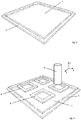
- Fig. 2 showed a printing plate 1 suitable for use in the method according to the invention.
- the printing plate 1 is made of quartz glass and has a frame 2.
- Fig. 3 shows the situation during the production of four frame-shaped molding layers 6 on the printing plate 1.
- a print head 3 of a 3D printer is used, which as described above in connection with Fig. 1 is described.
- the print head 3 can be moved in three spatial directions x, y and z (in the plane coplanar with the printing plate 1 and perpendicular thereto) and outputs the aforementioned plastically deformable mass in such a way that individual molded body layers 6 are built up layer by layer.
- Fig. 3a shows one way in which corresponding shaped body layers or portions thereof can be applied with a forming tool.
- a template 3 ' is thereby a plastically deformable mass (not shown) through the recesses 5 by means of a doctor blade 4 in the Fig. 2 plotted illustrated printing plate 1.
- the result is a printed image, which forms a shaped body layer of the molded body to be produced.
- Fig. 4 is the correspondingly printed printing plate 1 shown.
- Fig. 7 the construction of further molded body layers 6 'is shown. These are in turn generated by the print head 3 of the 3D printer. In contrast to the shaped body layers 6 Fig. 3 are the frame-shaped shaped body layers 6 'relative to the edges of the pressure plate 1 is now rotated by approximately 45 °.
- the plastically deformable mass (not shown) is printed on the printing plate 1.
- This reprinted printing plate is now also positioned over the substrate 7, which is in the Fig. 8 is shown.
- a polymerization step can be carried out simply by applying light of the correspondingly required UV wavelength through the transparent printing plate 1 to the shaped body layers 6, 6 'to be cured.
- the molded body layers 6 'enter into compounds with the older molded body layers 6, so that the resulting molded body is essentially in one piece.
- the connections can be material-locking. It can also lead to crosslinks in certain materials.
- Fig. 9 is the support 7 now shown with four moldings, which have two levels and consist of two integrally interconnected mold body layers 6, 6 '.
- Fig. 10 For example, four moldings are shown, in which the moldings consist of a total of three moldings 6, 6 ', 6 ", each of which has been produced in one printing operation.
- a shaped body with five layer planes is shown, which consists of five shaped body layers 6 "', 6"",6""',6""", 6 """'.
- the process according to the invention is also suitable for the production of three-dimensional shaped bodies as described in US Pat WO 2014/043823 A1 are shown. These moldings have a plurality of web-shaped superposed body layers.
- the shaped body layers of the present invention may have layer thicknesses of 10 ⁇ m to 50 mm. More preferably, they have layer thicknesses of between 50 and 3000 microns.
- a shaped body according to the invention can have outside dimensions of between 1 mm and 5000 mm, in particular between 4 and 500 mm, in particular between 10 and 300 mm, in particular around 50 mm, depending on the application. These sizes are particularly suitable for the production of micromixers and catalysts. For larger components in lightweight construction, the corresponding dimensions can be larger.
- a device 11 suitable for carrying out the method according to the invention is shown schematically.
- the device 11 comprises essentially a frame having the respective guides to operate the movable parts of the device.
- a rail system serves to position a substrate 16.
- This rail system comprises an X-axis of the positioning system 12, a Y-axis of the positioning system 14 and a Z-axis of the positioning system 13.
- the substrate 16 is connected to the Z-axis of the positioning system 13 via a pivotally mounted rotary joint 15. This makes it possible for the substrate to move in all axes to take the necessary positioning in order to carry out the method according to the invention.
- a print head 3 of a 3D printer with a reservoir for the mass to be used (not shown) is about three in Fig. 12 not shown arranged on the front of the device mechanical axes (analogous to the axes 12, 13, 14), in all three spatial directions on the pressure plate (not shown) movable.
- a shaping tool can be stored in a template magazine 21.
- this template magazine 21 it is possible to prepare a number of predefined forming tools, such as templates or screens.
- a changing device takes over the moving out of the templates 22 (by way of example) via the pressure plate (not shown).
- a squeegee 18 is positioned over the template 22 to smear the corresponding mass applied from an automatic dispensing system (not shown).
- the substrate 15 can be impregnated by means of an ink pad 17 with a suitable adhesion promoter.
- the positioning system of the substrate 16 can be determined by means of a vision system consisting of camera, lens and analysis software. This system is not shown in the present description for the sake of simplicity.
- the support 16 can be lowered by means of the positioning system on the printing plate and aligned exactly.
- a UV emitter 20 can now initiate polymerization and curing through the transparent printing plate.
- the support 16 can be lifted again.
- the shaped body layer is detached from the pressure plate and forms an older shaped body layer on the substrate 16.
- This device shown here is merely shown by way of example and can be expanded with several printing plates with associated stencil changing devices for the simultaneous printing of multiple components.
Landscapes
- Engineering & Computer Science (AREA)
- Chemical & Material Sciences (AREA)
- Materials Engineering (AREA)
- Manufacturing & Machinery (AREA)
- Mechanical Engineering (AREA)
- Physics & Mathematics (AREA)
- Optics & Photonics (AREA)
Applications Claiming Priority (1)
| Application Number | Priority Date | Filing Date | Title |
|---|---|---|---|
| CH00779/16A CH712596A2 (de) | 2016-06-17 | 2016-06-17 | Schichtweiser Aufbau von Formkörpern mit generativem Fertigungsverfahren. |
Publications (1)
| Publication Number | Publication Date |
|---|---|
| EP3278955A1 true EP3278955A1 (fr) | 2018-02-07 |
Family
ID=59061910
Family Applications (1)
| Application Number | Title | Priority Date | Filing Date |
|---|---|---|---|
| EP17176011.9A Withdrawn EP3278955A1 (fr) | 2016-06-17 | 2017-06-14 | Construction stratifiée de corps de formage selon le procédé de fabrication additive |
Country Status (2)
| Country | Link |
|---|---|
| EP (1) | EP3278955A1 (fr) |
| CH (1) | CH712596A2 (fr) |
Cited By (2)
| Publication number | Priority date | Publication date | Assignee | Title |
|---|---|---|---|---|
| DE102018212007A1 (de) * | 2018-07-18 | 2020-01-23 | Volkswagen Aktiengesellschaft | Verfahren und Vorrichtung zur Herstellung von dreidimensionalen Objekten im 3D-Druckverfahren |
| DE102019123128A1 (de) * | 2019-08-28 | 2021-03-04 | Cic Ceramic Institut Clausthal Gmbh | 3D-Siebdruckanlage und 3D-Siebdruckverfahren zur Herstellung eines Formkörpers |
Citations (8)
| Publication number | Priority date | Publication date | Assignee | Title |
|---|---|---|---|---|
| US6324440B1 (en) * | 1998-12-29 | 2001-11-27 | Lek Technologies, Llc | Apparatus for fabricating surface structures |
| US20090304952A1 (en) * | 2008-06-05 | 2009-12-10 | Kritchman Eliahu M | Apparatus and method for solid freeform fabrication |
| US20100215856A1 (en) * | 2009-02-24 | 2010-08-26 | Kritchman Eliahu M | Method and apparatus for three-dimensional printing |
| WO2014043823A1 (fr) | 2012-09-21 | 2014-03-27 | Hirschberg Engineering | Corps façonnnés tridimensionnels |
| US20150165690A1 (en) * | 2012-07-18 | 2015-06-18 | Adam P. Tow | Systems and methods for manufacturing of multi-property anatomically customized devices |
| US20150174821A1 (en) * | 2013-12-20 | 2015-06-25 | Xerox Corporation | Three dimensional (3d) printing of epoxy, hardener, and parts of an object to be assembled later |
| US20150246487A1 (en) * | 2007-07-04 | 2015-09-03 | Envisiontec Gmbh | Process and device for producing a three-dimensional object |
| US20160082156A1 (en) * | 2014-08-28 | 2016-03-24 | Christopher G. WILSON | Osteoinductive substrates and methods of making the same |
-
2016
- 2016-06-17 CH CH00779/16A patent/CH712596A2/de not_active Application Discontinuation
-
2017
- 2017-06-14 EP EP17176011.9A patent/EP3278955A1/fr not_active Withdrawn
Patent Citations (8)
| Publication number | Priority date | Publication date | Assignee | Title |
|---|---|---|---|---|
| US6324440B1 (en) * | 1998-12-29 | 2001-11-27 | Lek Technologies, Llc | Apparatus for fabricating surface structures |
| US20150246487A1 (en) * | 2007-07-04 | 2015-09-03 | Envisiontec Gmbh | Process and device for producing a three-dimensional object |
| US20090304952A1 (en) * | 2008-06-05 | 2009-12-10 | Kritchman Eliahu M | Apparatus and method for solid freeform fabrication |
| US20100215856A1 (en) * | 2009-02-24 | 2010-08-26 | Kritchman Eliahu M | Method and apparatus for three-dimensional printing |
| US20150165690A1 (en) * | 2012-07-18 | 2015-06-18 | Adam P. Tow | Systems and methods for manufacturing of multi-property anatomically customized devices |
| WO2014043823A1 (fr) | 2012-09-21 | 2014-03-27 | Hirschberg Engineering | Corps façonnnés tridimensionnels |
| US20150174821A1 (en) * | 2013-12-20 | 2015-06-25 | Xerox Corporation | Three dimensional (3d) printing of epoxy, hardener, and parts of an object to be assembled later |
| US20160082156A1 (en) * | 2014-08-28 | 2016-03-24 | Christopher G. WILSON | Osteoinductive substrates and methods of making the same |
Non-Patent Citations (1)
| Title |
|---|
| JOURNAL OF ENGINEERING, 2013 |
Cited By (3)
| Publication number | Priority date | Publication date | Assignee | Title |
|---|---|---|---|---|
| DE102018212007A1 (de) * | 2018-07-18 | 2020-01-23 | Volkswagen Aktiengesellschaft | Verfahren und Vorrichtung zur Herstellung von dreidimensionalen Objekten im 3D-Druckverfahren |
| DE102019123128A1 (de) * | 2019-08-28 | 2021-03-04 | Cic Ceramic Institut Clausthal Gmbh | 3D-Siebdruckanlage und 3D-Siebdruckverfahren zur Herstellung eines Formkörpers |
| DE102019123128B4 (de) | 2019-08-28 | 2023-11-02 | S.A.S 3Dceram-Sinto | 3D-Siebdruckanlage und 3D-Siebdruckverfahren zur Herstellung eines Formkörpers |
Also Published As
| Publication number | Publication date |
|---|---|
| CH712596A2 (de) | 2017-12-29 |
Similar Documents
| Publication | Publication Date | Title |
|---|---|---|
| EP3233427B1 (fr) | Méthode et dispositif pour la fabrication de corps façonnés | |
| EP2714354B1 (fr) | Procédé pour produire un corps moulé et dispositif correspondant | |
| DE60213267T2 (de) | Selektive materialablagerung mit vernetzbaren phasenwechselmaterialien | |
| WO2013182547A1 (fr) | Procédé de construction d'un moule en trois dimensions | |
| EP2275247A1 (fr) | Appareil et méthode de production d'objets tri-dimensionels au moyen d'un procédé de fabrication génératif | |
| EP3687763A1 (fr) | Pièces façonnées imprimées en 3d à partir de plus d'un matériau silicone | |
| DE102011117005A1 (de) | Verfahren zur Herstellung eines keramischen Formkörpers | |
| WO2020035456A1 (fr) | Procédé de fabrication d'un objet moulé tridimensionnel par dépôt de couches successives de matière | |
| WO2020094246A2 (fr) | Procédé de fabrication d'un objet moulé tridimensionnel par dépôt de couches successives de matière | |
| EP1523413B1 (fr) | Procede et dispositif pour la production d'un timbre | |
| DE102014010412B4 (de) | Verfahren und Anordnung zur generativen Fertigung von Bauteilen | |
| EP3278955A1 (fr) | Construction stratifiée de corps de formage selon le procédé de fabrication additive | |
| DE102014111559B4 (de) | Verfahren zur Herstellung von Schichtenfolgen und Formkörpern aus einer Anzahl von Schichten | |
| WO2022022763A1 (fr) | Procédé de production d'un article façonné en 3d et dispositif utilisant un plateau perforé | |
| EP3305495B1 (fr) | Procédé de génération d'une structure tridimensionnelle dans une matrice | |
| EP4021703B1 (fr) | Installation de sérigraphie 3d et procédé de sérigraphie 3d pour la production d'un objet | |
| EP3774289B1 (fr) | Procédé et dispositif pour la fabrication additive continue ou quasi continue de pièces | |
| WO2009149984A2 (fr) | Fabrication additive - impression 3d | |
| EP3890949A1 (fr) | Procédé et dispositif de fabrication d'un objet tridimensionnel | |
| EP3854570B1 (fr) | Procédé de fabrication d'une pièce moulée tridimensionnelle | |
| DE60306925T2 (de) | Verfahren zum ausrichten und verbinden von beschichtungen zum formen eines formteils, vorrichtung zur herstellung eines formteils | |
| DE102016219191A1 (de) | Verfahren und Vorrichtung zur Erzeugung einer dreidimensionalen Struktur in einer Matrix | |
| DE102016219088B4 (de) | Verfahren und Vorrichtung zur generativen Herstellung von Bauteilen oder die Ausbildung von Beschichtungen auf Oberflächen von Bauteilen | |
| EP3807025A1 (fr) | Procédé destiné à fabriquer un composant en appliquant des éléments de volume discrets remplis de particules | |
| DE102021107281A1 (de) | 3d-druckvorrichtung und 3d-druckverfahren |
Legal Events
| Date | Code | Title | Description |
|---|---|---|---|
| PUAI | Public reference made under article 153(3) epc to a published international application that has entered the european phase |
Free format text: ORIGINAL CODE: 0009012 |
|
| STAA | Information on the status of an ep patent application or granted ep patent |
Free format text: STATUS: THE APPLICATION HAS BEEN PUBLISHED |
|
| AK | Designated contracting states |
Kind code of ref document: A1 Designated state(s): AL AT BE BG CH CY CZ DE DK EE ES FI FR GB GR HR HU IE IS IT LI LT LU LV MC MK MT NL NO PL PT RO RS SE SI SK SM TR |
|
| AX | Request for extension of the european patent |
Extension state: BA ME |
|
| STAA | Information on the status of an ep patent application or granted ep patent |
Free format text: STATUS: THE APPLICATION IS DEEMED TO BE WITHDRAWN |
|
| 18D | Application deemed to be withdrawn |
Effective date: 20180808 |