EP3278955A1 - Layer-based assembly of moulds with generative manufacturing method - Google Patents
Layer-based assembly of moulds with generative manufacturing method Download PDFInfo
- Publication number
- EP3278955A1 EP3278955A1 EP17176011.9A EP17176011A EP3278955A1 EP 3278955 A1 EP3278955 A1 EP 3278955A1 EP 17176011 A EP17176011 A EP 17176011A EP 3278955 A1 EP3278955 A1 EP 3278955A1
- Authority
- EP
- European Patent Office
- Prior art keywords
- shaped body
- body layer
- printing plate
- layer
- substrate
- Prior art date
- Legal status (The legal status is an assumption and is not a legal conclusion. Google has not performed a legal analysis and makes no representation as to the accuracy of the status listed.)
- Withdrawn
Links
Images


Classifications
-
- B—PERFORMING OPERATIONS; TRANSPORTING
- B29—WORKING OF PLASTICS; WORKING OF SUBSTANCES IN A PLASTIC STATE IN GENERAL
- B29C—SHAPING OR JOINING OF PLASTICS; SHAPING OF MATERIAL IN A PLASTIC STATE, NOT OTHERWISE PROVIDED FOR; AFTER-TREATMENT OF THE SHAPED PRODUCTS, e.g. REPAIRING
- B29C64/00—Additive manufacturing, i.e. manufacturing of three-dimensional [3D] objects by additive deposition, additive agglomeration or additive layering, e.g. by 3D printing, stereolithography or selective laser sintering
- B29C64/10—Processes of additive manufacturing
-
- B—PERFORMING OPERATIONS; TRANSPORTING
- B29—WORKING OF PLASTICS; WORKING OF SUBSTANCES IN A PLASTIC STATE IN GENERAL
- B29C—SHAPING OR JOINING OF PLASTICS; SHAPING OF MATERIAL IN A PLASTIC STATE, NOT OTHERWISE PROVIDED FOR; AFTER-TREATMENT OF THE SHAPED PRODUCTS, e.g. REPAIRING
- B29C64/00—Additive manufacturing, i.e. manufacturing of three-dimensional [3D] objects by additive deposition, additive agglomeration or additive layering, e.g. by 3D printing, stereolithography or selective laser sintering
- B29C64/20—Apparatus for additive manufacturing; Details thereof or accessories therefor
- B29C64/205—Means for applying layers
- B29C64/209—Heads; Nozzles
-
- B—PERFORMING OPERATIONS; TRANSPORTING
- B29—WORKING OF PLASTICS; WORKING OF SUBSTANCES IN A PLASTIC STATE IN GENERAL
- B29C—SHAPING OR JOINING OF PLASTICS; SHAPING OF MATERIAL IN A PLASTIC STATE, NOT OTHERWISE PROVIDED FOR; AFTER-TREATMENT OF THE SHAPED PRODUCTS, e.g. REPAIRING
- B29C64/00—Additive manufacturing, i.e. manufacturing of three-dimensional [3D] objects by additive deposition, additive agglomeration or additive layering, e.g. by 3D printing, stereolithography or selective laser sintering
- B29C64/20—Apparatus for additive manufacturing; Details thereof or accessories therefor
- B29C64/205—Means for applying layers
- B29C64/223—Foils or films, e.g. for transferring layers of building material from one working station to another
-
- B—PERFORMING OPERATIONS; TRANSPORTING
- B29—WORKING OF PLASTICS; WORKING OF SUBSTANCES IN A PLASTIC STATE IN GENERAL
- B29C—SHAPING OR JOINING OF PLASTICS; SHAPING OF MATERIAL IN A PLASTIC STATE, NOT OTHERWISE PROVIDED FOR; AFTER-TREATMENT OF THE SHAPED PRODUCTS, e.g. REPAIRING
- B29C69/00—Combinations of shaping techniques not provided for in a single one of main groups B29C39/00 - B29C67/00, e.g. associations of moulding and joining techniques; Apparatus therefore
-
- B—PERFORMING OPERATIONS; TRANSPORTING
- B33—ADDITIVE MANUFACTURING TECHNOLOGY
- B33Y—ADDITIVE MANUFACTURING, i.e. MANUFACTURING OF THREE-DIMENSIONAL [3-D] OBJECTS BY ADDITIVE DEPOSITION, ADDITIVE AGGLOMERATION OR ADDITIVE LAYERING, e.g. BY 3-D PRINTING, STEREOLITHOGRAPHY OR SELECTIVE LASER SINTERING
- B33Y10/00—Processes of additive manufacturing
-
- B—PERFORMING OPERATIONS; TRANSPORTING
- B33—ADDITIVE MANUFACTURING TECHNOLOGY
- B33Y—ADDITIVE MANUFACTURING, i.e. MANUFACTURING OF THREE-DIMENSIONAL [3-D] OBJECTS BY ADDITIVE DEPOSITION, ADDITIVE AGGLOMERATION OR ADDITIVE LAYERING, e.g. BY 3-D PRINTING, STEREOLITHOGRAPHY OR SELECTIVE LASER SINTERING
- B33Y30/00—Apparatus for additive manufacturing; Details thereof or accessories therefor
Definitions
- the present invention relates to processes for the production of moldings from at least one molding layer. It further relates to devices for producing a shaped article of at least one molding layer and the use of said moldings, all according to the preambles of the independent claims.
- 3-D printing is a manufacturing process used to build three-dimensional workpieces step by step and automatically. Normally, a predefined shape is generated from a starting material during 3-D printing. Typical materials used in 3-D printing are plastics, resins, ceramics and metals. In particular, in the current very rapid rapid prototyping should be produced as possible without manual effort a variety of possible shapes and structures. The focus here is on the versatility of the printing machine in order to replicate structurally and step-by-step the user-defined shape from the moldable material as the starting material. These devices and methods are, as the name implies, the production of "prototypes", ie largely individual pieces. Accordingly, most devices and methods are unsuitable for industrial mass production because they do not have high turnover and are material and energy consuming.
- 3D printing can be used to produce industrial and technical moldings.
- WO 2014/043823 A1 Hirschberg Engineering
- These shaped bodies have branched webs and layers, which are particularly suitable for applications in fluid-driven processes.
- the shaped bodies shown can be used as static mixers or heat exchangers or for emulsification or foaming of substances or as catalytic surfaces in chemical reactions.
- the moldings are produced by applying a plastically deformable mass layer by layer through a stencil.
- the layers may be cured stepwise or at the end after the finished molded article is cured. Each layer is applied to the previous layer by a suitable template. Hardening is by means of drying, UV curing or otherwise induced curing.
- the recesses of the template used as a mask or sieve determine the shape of the respective layers.
- One aspect of the present invention relates to a process for the production of moldings from at least one molding layer.
- the method according to the invention comprises a series of steps.
- a substrate for receiving at least one molding layer is provided.
- a shaped body layer is applied to a printing plate, wherein the shaped body layer is at least partially, in particular completely, produced by a generative manufacturing method or applied to said printing plate.
- method steps which do not necessarily follow one another logically or in which a sequence is not explicitly mentioned need not be executed exclusively in the order in the present enumeration.
- the provision of the layer support for example, take place at the same time as the application of the shaped body layer to the printing plate.
- the inventive method further comprises the step that the pressure plate and the substrate are positioned relative to each other. At this time, a first or a plurality of older shaped-body layers, which have been transferred to them in previous passes of the method according to the invention, may already be present on the substrate.
- the method according to the invention can be carried out with a single printing plate. But it is also possible to use several different printing plates, which are used in particular simultaneously, sequentially and / or alternately. This may speed up the process or simplify the production of complex structures.
- the relative positioning of the printing plate can be understood as meaning that either the printing plate or the substrate or both perform a movement in which the molding layer is contacted on the printing plate with either the substrate or any older molding layer already thereon.
- printing plate and substrate are preferably positioned relative to each other so that the shaped body layer is exactly aligned as desired on the substrate during transfer from the printing plate to the substrate.
- the shaped body layer is cured.
- a hardened shaped body layer becomes an older shaped body layer or merges with an already existing older shaped body layer.
- This curing step may take place in particular at the time when the pressure plate and the substrate are positioned relative to each other. In this state, the substrate and printing plate can form mechanical supports for the as yet uncured molded body layer.
- the shaped body layer of the current process step can be transferred to one or more older shaped body layer (s), wherein correspondingly the pressure plate or the older (s) shaped body layer (s) are positioned relative to each other. Transferring the shaped body layer involves peeling off the printing plate. For later runs, the cured, transferred shaped body layer thus becomes an older shaped body layer.
- an older shaped body layer is defined in relation to the current shaped body layer. That is, each mold body layer preceding a mold body layer is an older mold body layer with respect to it.
- the shaped body layers can be numbered by number. So the first is transmitted on a support Shaped body layer, the first shaped body layer.
- the first mold body layer with respect to the second would be the older mold body layer.
- the number of repetitions passed depends on the desired final shape of the resulting molded article and can be selected individually by the person skilled in the art.
- the last step of the method according to the invention comprises the eventual provision of the printing plate for receiving further shaped body layers and the subsequent repeating of the abovementioned method steps.
- an older shaped-body layer is at the same time a hardened shaped-body layer.
- the shaped body resulting from the method according to the invention is constructed from at least one shaped body layer in that it is a direct result of the method.
- the resulting shaped bodies are not limited to the recognizability of the individual shaped body layers that is conditional upon conclusion of the process.
- the resulting molded articles are not limited to rectangular, flat layers or layers of homogeneous thickness.
- shaped body layers or parts thereof can be quickly built up and applied automatically.
- the method according to the invention is particularly suitable for mass production.
- the term "generative manufacturing process” or “additive manufacturing” refers to processes in which a spatial object is generated by targeted spatial deposition, application and / or solidification of material.
- the spatial object consists of a shaped body layer.
- the deposition, application and / or solidification of the material takes place, in particular, on the basis of a data model of the object to be produced or the shaped body layer and, in particular, in layers.
- Each individual shaped body layer can thus be produced in the additive manufacturing process from one or more layers.
- an informal material eg from liquids, powders, granules, etc.
- a form-neutral material eg ribbons, wires
- Generative manufacturing processes are known per se to those skilled in the art and are also referred to inter alia as “additive manufacturing processes” or “additive manufacturing”.
- the additive manufacturing process is a tool-free and / or informal process.
- no mold and / or molding tool is used for the additive manufacturing process.
- the generative production method may in particular be a powder bed process, a free-space process and / or a liquid material process.
- the material to be processed is applied in powder form in a thin layer on a base plate or printing plate.
- the material to be processed is then solidified locally, in particular in layers, so that the object to be produced or the shaped body layer is generated. Excess and unconsolidated powder is removed.
- the solidification of the powder can be achieved by targeted local energy input, e.g. with an electromagnetic radiation source (for example a laser) or an electron beam source. It is known e.g. following methods: selective laser melting, laser sintering, electron beam melting.
- a chemical reactant e.g. a binder
- the powder material is bonded at the selected locations with the binder and thereby solidified. This is also called binder jetting.
- the powder bed process is selective laser melting, laser sintering, electron beam melting and / or binder jetting.
- the material to be processed is in liquid form.
- the solidification is typically carried out by targeted local energy input into the liquid.
- a light-curing material is selectively locally cured by a laser beam.
- plastics in particular photopolymers, such as acrylic, epoxy and / or vinyl ester resins, used.
- the liquid material method is a stereolithography method.
- the material to be processed is applied only at those points where the object to be generated or the shaped body layer is to arise. In contrast to the powder method, the free space method therefore does not fill the entire installation space with material to be processed.
- the material to be processed is present as a raw material, in particular in a solid form, e.g. as a powder, filament and / or granules. It is also possible that the material to be processed is in liquid form.
- open space methods are known e.g. Fused Deposition Modeling or extrusion process.
- melt-layer processes the material to be processed, e.g. as a strand, conveyed through a heating nozzle and heated to the extent that it melts and can be extruded through the nozzle.
- the material to be processed in particular a plastically deformable mass, e.g. a paste, discharged through a nozzle and solidified and / or cured in a subsequent step. It can also be dispensed with a heating.
- a plastically deformable mass e.g. a paste
- the additive manufacturing process is a free-space process, in particular a melt-coating process and / or an extrusion process.
- extrusion processes are particularly preferred in combination with the further process steps of the process according to the invention.
- they have the advantage that only the amount of material to be processed which is necessary for the production of the object and no removal of excess material, e.g. Powder or liquid, is required.
- the shaped body layer is produced on the pressure plate from a plastically deformable mass, in particular a paste.
- a plastically deformable mass in particular a paste
- Such pastes can be processed in particular without heating and already have a certain dimensional stability after application. Find more information about the plastic masses down below. However, in principle it is also not possible to use plastically deformable materials.
- the dispensing device may also be referred to as a dispenser.
- the dispensing device used is movable in particular in a coplanar plane to the printing plate.
- the pressure plate can be designed to be movable in a direction perpendicular to the plane of the pressure plate. This allows almost any objects or mold layers to be produced on the printing plate.
- the discharge device is additionally movable in a direction perpendicular to the plane of the printing plate. By such movable discharge devices can be formed on the printing plate almost arbitrarily shaped objects.
- the discharge device used in particular comprises at least one nozzle for discharging the material to be processed, in particular a plastically deformable mass.
- the dispensing device used in the method comprises a plurality of, in particular 2 - 256 or 32 - 128, individually addressable and / or individually movable nozzles.
- the discharge device is in particular designed such that it can discharge the material to be discharged in individual drops having a volume of 0.1-100 pL, in particular 1-50 pL.
- the discharge device advantageously has a temperature controller with which a temperature of the material to be discharged and / or a nozzle can be controlled.
- the discharge device is an inkjet printer, a plotter, a 2D printer and / or a 3D printer.
- the material to be processed or the plastically deformable mass has a viscosity of 10 - 10 6 mPa ⁇ s, preferably 100 - 10 5 mPa ⁇ s. Viscosities are determined in the present context, in particular at 25 ° C, preferably according to the Brookfield method and in particular according to DIN EN ISO 2555: 2000-01.
- the material to be processed in particular a plastically deformable mass, before step b) with a solvent, in particular water, diluted.
- a viscosity of the diluted material to be processed or the plastically deformable mass is reduced, in particular so that the viscosity in the range of 10 - 10 6 mPa ⁇ s, preferably 100 - 10 5 mPa ⁇ s, is.
- the solvent is advantageously matched to the chemical composition of the material to be processed, in particular the plastically deformable mass.
- it is water, alcohols, e.g. Ethanol, and / or organic solvents.
- the material to be processed in particular the plastically deformable mass
- the drying process takes place with advantage before step c).
- a drying process is a process in which a proportion of solvent and / or other liquid constituents in the plastically deformable mass is reduced. In particular, bleeding of low-viscosity and / or previously diluted material to be processed, in particular plastically deformable mass, can thus be prevented.
- the shaped body layer is applied in step b) partly by a generative manufacturing process and partly by a shaping tool on the printing plate.
- a generative manufacturing process for example, different regions of a shaped body layer can be produced by an optimum method adapted to the structure in the respective region and / or from different materials.
- complex structural elements of a Shaped body layer are generated by the generative process, while simpler elements are applied by the forming tool. This can benefit the overall efficiency of the process.
- the method according to the invention additionally comprises a further step b '), in which a shaped body layer is applied to the printing plate by means of a shaping tool.
- Step b ') can take place before and / or after a first execution of steps a) to d), for example in the step sequence a), b'), c) and d).
- individual shaped body layers can be produced entirely by a shaping tool.
- this measure can also contribute to speeding up the process as a whole.
- the forming tool is a template.
- the template can be designed so that it can be positioned as a flat surface over the printing plate.
- Recesses in the stencil define the shape of the shaped body layer applied by the respective stencils and / or the shape of partial regions of the shaped body layer.
- a stencil or forming tool can define a variety of identical or different shapes for shaped body layers and / or subregions of shaped body layers.
- the forming tool is a sieve, in particular a sieve for technical screen printing.
- a further advantage of the method according to the invention is that the step of applying the shaped body layer to the substrate is carried out indirectly, that is to say that first of all the shaped body layer with already defined shape is transferred onto the substrate from a printing plate. Thanks to this indirect printing process, the present process may also involve a combination of additive manufacturing processes and printing processes with forming tools, e.g. Screen and stencil printing.
- the pressure plate is configured just. This simplifies the construction of moldings in general. Will the Molded body layers or parts thereof produced with an additional shaping tool, this has the further advantage that, especially for stencil printing a perfectly flat surface provides particularly good results in printing the individual moldings layers. But even with screen printing, a flat printing plate is advantageous for the printing result of the individual shaped body layers.
- the pressure plate is designed such that the shaped body layer adheres poorly thereto.
- the shaped body layer is transferred from the printing plate to the support or the older shaped body layer.
- the adhesion of a cured paste to a surface depends on the surface shape as well as on the mating surface - paste. For low adhesion, a chemical compound of the paste with the surface must be excluded, the structure of the surface should be smooth and the surface should have the lowest possible surface energy. Surface energies of less than 40 mN / m, in particular surface energies of less than 30 mN / m, and in particular surface energies of less than 20 mN / m, are considered low for the purposes of the present application.
- the material of the printing plate is designed such that the shaped body layer adheres poorly thereto.
- the surface of the printing plate may be processed such that the shaped body layer easily peels off in the corresponding transfer step. Basically, this is possible by a surface treatment of the printing plate.
- This surface treatment can be permanent, that is, the printing plate is provided with a corresponding surface treatment that has already taken place in the production process of the printing plate.
- the printing plate may be equipped with a temporary system of surface treatment. It is for example it is possible to coat the printing plate with a wax or resin or a powder, which is consumed in the course of the applications of the printing plate and must be applied repeatedly. Accordingly, in an apparatus for carrying out the method according to the invention, structures may be provided which perform this coating at periodic intervals or before each application of the printing plate.
- the adhesion of the printing plate is lowered by means of Einbrennsilikonmaschine.
- the printing plate is provided with a coating containing fluoropolymers.
- the adhesion of the printing plate is lowered by means of a layer of polydimethylsiloxane or other polysilanes.
- a thin coating is applied to the printing plate prior to each use.
- layers containing fat or wax are applied to the printing plate before each application.
- dry lubricants or dry lubricating layers as known from dry lubrication of plain bearings, can be used to lower the adhesive properties of the printing plate.
- Transparent dry sliding layers based on synthetic waxes are preferred.
- thermally treated silicate layers are used.
- Water-soluble sodium silicates, lithium silicates or potassium silicates can be applied in liquid form and solidify on drying to glassy, amorphous layers.
- pastes with acrylic-based photopolymers are used to form the shaped body layers, it has surprisingly been found that a coating of the printing plate with a thin layer of sodium silicate, which is heated to about 100 ° C for half an hour prior to use in an oven, is particularly gives good results.
- the older shaped-body layer on the support or the support itself is provided with a bonding agent in one process step before a next further molding-body layer is transferred thereon becomes.
- This step preferably comprises dipping, spraying or wetting by means of an ink pad of the substrate with said adhesion promoter.
- An adhesion promoter can lead to the connection between the current shaped body layer and the older shaped body layer being improved.
- the end face of the older shaped-body layer, which has already hardened, is wetted, for example, with a low-viscosity adhesion promoter.
- different adhesion promoters can be used.
- monomers without photoinitiator can be used which crosslink only in contact with the pastes containing the corresponding photoinitiator. Where the new shaped body layer does not touch the older, already cured molding layer, this bonding agent remains liquid even under the effect of UV radiation.
- photoinitiators can alternatively also be added to the monomer used as adhesion promoter.
- the thin monomer layers do not cure in this case if they are not covered by the paste of the new shaped body layer, since the very thin adhesion promoter layers, the polymerization is inhibited by the oxygen in the air.
- a material to be processed in particular a plastically deformable mass, is applied through the recesses of the shaping tool to the printing plate to form the shaped body layer or subregions thereof.
- Suitable materials to be processed, in particular plastically deformable materials can be selected by the skilled person depending on the desired field of application, the intended curing process and the availability of material.
- the materials to be processed preferably have suitable rheological properties for use in the additive manufacturing processes and / or for printing by the optional shaping tools.
- moldable compositions which have thixotropic properties.
- Such moldable or plastically deformable masses flow well under shear stress, but are also dimensionally stable on the printing plate.
- suspensions Particularly suitable are suspensions.
- Suspensions may have as their main component fine-grained powder, which is selected according to the material of the desired shaped body. For example, metals, metal alloys, stainless steel or precious metals as well as ceramics and / or glass ceramics are suitable.
- organic binders are added to form a plastically deformable material.
- organic binders Materials which can be used as, for example, organic binders include CMC (carboxymethyl cellulose), polyolefin, and various forms of natural starch (corn flour, wheat flour, etc.).
- CMC carboxymethyl cellulose
- polyolefin polyolefin
- various forms of natural starch corn flour, wheat flour, etc.
- photopolymers can be used as organic binders.
- Photopolymers are monomers and oligomers, as well as mixtures thereof, which begin to polymerize by the action of light radiation, typically in the ultraviolet range, due to the action of a photoinitiator admixed in small amounts, typically less than 5%. There are a large number of different photopolymers.
- acrylic monomers such as, inter alia, for example, hexane-1,6-diol diacrylate, trimethylpropane triacrylate, poly (ethylene glycol) diacrylate, which are mixed with small amounts of photoinitiators such as, for example, 0.5% of 2,2-dimethoxy-2-phenylacetophenones were, as binder material in question.
- photoinitiators such as, for example, 0.5% of 2,2-dimethoxy-2-phenylacetophenones were, as binder material in question.
- these monomers can be mixed with different oligomers of polyacrylates.
- the material to be processed in particular a plastically deformable mass
- a sintering step as is often the case with ceramics, metals or glass, for example, it contains a high proportion by volume of the powder to be sintered, in particular of> 35% by volume, more particularly > 50 volume percent.
- the materials to be processed have additional additives which can be used to alter the rheological properties of the materials, such as dispersion aids.
- additional additives which can be used to alter the rheological properties of the materials, such as dispersion aids.
- Such additives are known to the person skilled in the art and can be selected by him / her according to the required conditions ( Journal of Engineering, Volume 2013 (2013), Article ID 930832 ).
- the material to be processed in particular the plastically deformable mass, comprises pure plastic parts. These may have corresponding monomers and / or oligomers which are later polymerized. Such materials to be processed, in particular plastically deformable masses, may also contain additional additives to adjust the rheological properties, as well as solvents, pigments, catalysts or biocides.
- the material to be processed in particular the plastically deformable mass, may contain powders of a base material as a suspension selected from the group comprising: metals, steel alloys, hard metals, non-ferrous metals, precious metals, ceramics, metal-ceramic composites, glass, Plastics and / or plastic composites with fiber reinforcement or metal or ceramic particles. Mixtures of these materials are conceivable.
- a shaped body layer is constructed from a plurality of partial shaped body layers which are printed simultaneously and / or successively individually on the printing plate and / or on a plurality of different printing plates.
- the partial molded body layers can be produced using a generative production method and / or with a shaping tool.
- a first partial molded body layer can be produced on a first printing plate with a generative manufacturing method and a second partial molded article layer with a forming tool on a second printing plate. Then, the partial molded body layers are simultaneously and / or sequentially positioned in step c) of the process and cured in step d).
- the individual partial molded body layers can consist of the same or of different pastes, whereby it is possible to produce shaped body layers which are made up of a plurality of different materials.
- a plurality of plastically deformable masses having different properties are produced by (i) various devices for carrying out the additive manufacturing process, (ii) at least one device for carrying out the additive manufacturing process and at least one shaping tool and / or (iii) applied by at least one forming tool with different recesses of the forming tool on the printing plate to form the shaped body layer.
- a molded body layer consisting of different materials can be formed.
- These embodiments can be provided, for example, in the desired end product, that is to say moldings. Another possible application would be to use one or more additional materials which are later modified. These can be used as filling or support structures, which give the body under construction during the building process better stability. Later, these filling or support structures can be removed again by mechanical, chemical or thermal processes from the molding.
- the method according to the invention advantageously comprises a thermal treatment of the shaped body for sintering the completion of the molding process of the molding is performed.
- the molding is sintered at temperatures of between 500 and 2500 ° C, preferably between 600 and 1700 ° C.
- the layer carrier is designed such that the shaped body layers adhere well to it. This can be controlled by the choice of the material of the support or by a coating of the support. If the support is not to be used in a thermal treatment subsequent to the structure of the molded article, for example, an aluminum alloy is a suitable material for a support for acrylic-based photopolymer pastes.
- the substrate is designed so that it is suitable as a carrier for the sintering process.
- the support must be designed so that it can withstand the temperatures generated in the sintering step, without prejudice.
- the substrate is made of a ceramic material, such as alumina, corundum, silicon carbide or sapphire.
- graphite or carbon fiber can also be used as the material for the substrate.
- the mold layer must adhere well to the substrate.
- the molded body produced must be released from the composite body, so that the molding body relative to the substrate expand unhindered resp. in particular can shrink.
- the support is preferably provided with a coating.
- the support is provided with a Polivinylbutyral (PVB) layer.
- PVB Polivinylbutyral
- the process according to the invention comprises a polymerization step. It is preferably a polymerization step selected from the group consisting of: photoinduced, thermoinduced and / or chemoinduced polymerisation.
- the process according to the invention particularly preferably has a photopolymerization step.
- a shaped body layer is cured on the printing plate and in contact with the substrate or the older, already cured mold carrier layers.
- the appropriately selected material to be processed in particular the correspondingly selected plastically deformable mass
- the shaped body layer preferably takes place through the pressure plate.
- the printing plate for the light of appropriate wavelength must be transparent. Depending on the photoinitiator used, a different wavelength is required.
- the photopolymerization is initiated with short-wave light, ie light in the ultraviolet spectrum.
- a pressure plate made of quartz glass or sapphire glass has proven to be suitable.
- the printing plate is selected from a material which does not change its transmittance for UV light over an extended period of time.
- the curing of the shaped body layer can be effected by a physical process, such as drying and / or drying Cooling.
- the material to be processed would be applied as a melt, which solidifies after cooling.
- the process according to the invention could also be carried out with a thermoplastic as a material to be processed or a plastically deformable mass.
- the curing could take place by means of drying and / or complexing and / or crystallization, as occurs, for example, in the evaporation of a solvent in an adhesive or in the hardening of cements.
- the printing plate and the support are positioned relative to each other so that the mold body layer on the printing plate touches the support or the older mold body layer and is aligned on the support or relative to the older mold body layers exactly as it is for the production of the desired Shaped body is necessary.
- the layer thickness of each shaped body layer is constant.
- the layer thicknesses of the individual co-applied shaped body layers are variable.
- the use of a generative manufacturing method makes it possible to realize such embodiments in a particularly advantageous and flexibly applicable manner.
- a shaping tool When using a shaping tool, for example, a shaping tool could be selected which has recesses for defining a plurality of different shaped body layers and / or subregions thereof. All of these shaped body layers and / or subregions thereof may have the same layer thickness.
- the shaping tool can also be designed so that it applies different layer thicknesses. In accordance with the choice of the sequence of the shaping tools and the corresponding shaped body layers and / or subregions thereof, particularly complex structures can thus be constructed.
- the printing plate can be designed such that it precisely measures the transfer of the shaped body layer onto the layer carrier or the older shaped body layer positioned.
- particularly small, filigree or nested shaped body layers can be constructed and designed as a molded body.
- the pressure plate is substantially rigid.
- the printing plate can be regarded as essentially rigid if it undergoes no appreciable deformation in the operation according to the invention.
- the pressure plate withstands material and / or design of a deflection. This is insofar material and / or design-related, as that the resistance to a bending torque is dependent on the rigidity of the material and the size of the cross section of the pressure plate.
- the pressure plate is designed as a film.
- the transfer of the shaped body layer (s) from the film to the substrate can be accomplished by peeling off the film.
- peeling would mean flexing of the film in at least one areal extent and would be comparable to peeling off a patch or adhesive tape.
- an already crosslinked and / or cured molded body layer could be better removed by stripping the film from the contact surface of the shaped body layer.
- the layer thickness of the film is preferably less than 2,000 ⁇ m, in particular 10-2,000 ⁇ m, particularly preferably 50-500 ⁇ m, in particular 50-200 ⁇ m, very particularly preferably 100 ⁇ m.
- the film is held rigidly in the transfer to the substrate.
- the film is placed on a rigid base.
- the film is permeable to polymerization-inducing electromagnetic radiation, in particular permeable to UV radiation.
- the curing of the substrate can still take place in contact with the film, which can then be removed from the molding layer with less effort.
- the film is at least the Contact side which carries the shaped body layer provided with a non-stick coating or consists of a plastic with appropriate properties.
- Suitable materials for an anti-adhesion coating of the film are fluorinated hydrocarbons, such as FEP (fluorinated ethylene-propylene), EFTE (ethylene-tetrafluoroethylene) or polytetrafluoroethylene (Teflon, DuPont).
- FEP and EFT also have the advantage of good transmission of UV radiation.
- Another aspect of the present invention relates to an apparatus for producing a shaped body from at least one shaped body layer. It goes without saying that the corresponding device may be provided with structural features in order to have any combination and possibility of the above-mentioned method features which are not mutually exclusive.
- a device comprises one or more supports for receiving at least one shaped body layer. It further comprises one or more pressure plate (s) and at least one device for carrying out a generative production process, by means of which a shaped body layer or partial regions thereof with a defined shape can be produced on the pressure plate.
- printing plate and / or support are designed so that applied shaped body layers can be positioned relative to each other and transferable to the support or an already existing on the support older mold body layer.
- the device is designed so that it allows a precise alignment of the printing plate and the substrate relative to each other.
- the device for carrying out the generative manufacturing process is a movable in a least two space dimensions, in particular three space dimensions, in particular a movable printhead.
- the discharge device is movable in particular in a coplanar plane to the printing plate.
- the pressure plate can be designed to be movable in a direction perpendicular to the plane of the pressure plate. This allows almost any objects or mold layers to be produced on the printing plate.
- the discharge device is additionally in one Direction perpendicular to the plane of the pressure plate movable.
- the discharge device comprises in particular at least one nozzle for discharging the material to be processed, in particular a plastically deformable mass.
- the discharge device comprises a plurality of, in particular 2 - 256 or 32 - 128, individually addressable and / or individually movable nozzles.
- the dispensing device is designed such that it can dispense the material to be dispensed into individual drops with a minimum volume of 0.1-100 pL, in particular 1-50 pL.
- the discharge device advantageously has a temperature controller with which a temperature of the material to be discharged and / or a nozzle can be controlled.
- the discharge device is an inkjet printer, a plotter, a 2D printer and / or a 3D printer
- the substrate is designed so that it is substantially flat and hardly deformed.
- the support can be designed so that it withstands the operating temperatures of the device without plastically deforming.
- a suitable substrate may be sufficiently thick that it does not deform.
- the concrete dimensions can, respectively, to the dimensions of the printing plate. be adapted to the mold layers.
- the pressure plate is movably arranged, in particular rotatably arranged.
- the printing plate for light waves is permeable, in particular, the printing plate is transparent to UV light.
- the printing plate is essentially made of quartz glass or sapphire glass.
- the pressure plate is provided with at least one adhesion-reducing surface.
- the pressure plate is made of a material that substantially reduces the amount of adhesion.
- the printing plate is provided with an adhesion-reducing surface selected from the group consisting of: burn-in-siliconized surface, polysilane coating, fluoropolymer coating, greasy coating, wax-containing coating, and / or silicate coating.
- the Schichthariso is designed so that it has high rigidity and chemical inertness even under thermal stress, preferably at temperatures of about 500 ° C, more preferably above 800 ° C.
- the support is particularly preferably made of a material such as alumina, corundum, silicon carbide or sapphire.
- the device also comprises at least one shaping tool, in particular a plurality of shaping tools.
- each shaping tool recesses on resp. is designed to define a different shape.
- the shaping tool is configured such that a plurality of mold layers and / or portions thereof are printed together in one printing operation, which are then aligned one after the other relative to the substrate respectively the older mold layers, cured and released from the printing plate. This makes it possible to reduce the number of different printing stencils or printing screens.
- the device comprises a means for applying an adhesion promoter to a shaped body layer on the substrate.
- the device comprises a spraying device, or a roller or an ink pad for applying an adhesion promoter to a shaped body layer and / or to the substrate.
- the device comprises a squeegee for spreading a deformable mass on the forming tool, so that a shaped body layer and / or portions thereof is applied through recesses of the forming tool on the printing plate.
- the pressure plate is substantially rigid.
- the printing plate can be regarded as essentially rigid if it undergoes no appreciable deformation in the operation according to the invention.
- the pressure plate withstands material and / or design of a deflection. This is insofar material and / or design-related, as that the resistance to a bending torque is dependent on the rigidity of the material and the size of the cross section of the pressure plate.
- the printing plate is provided as a film, in particular it is ensured by its cross-sectional thickness and / or material properties that it is sufficiently flexible in at least one surface extent that a reversible deflection is possible, so that the film can be removed from a cured molding layer ,
- the film comprises a coating which itself is very inert, and has a low coefficient of friction.
- the coating has a dynamic coefficient of friction of less than 0.1.
- the material has a dynamic coefficient of friction which is equal to the coefficient of static friction of the said material.
- the film is made of such a material.
- the film preferably comprises, or consists of, a material consisting of the group of the fluorinated hydrocarbons, more preferably FEP and / or ETFE.
- a further aspect of the present invention relates to the use of a shaped body resulting from a method according to the invention for producing three-dimensional microstructures for process engineering applications.
- shaped bodies with complex cavities and capillaries can be produced in their interior.
- the moldings produced can also be advantageous for the automotive industry, the Aircraft and wind turbines are used, since they are particularly suitable to produce lightweight structures.
- the method according to the invention allows materials with different electrical properties to be combined, it is possible in a particular embodiment to produce molded articles which contain electrical conductor tracks.
- materials with different magnetic properties including permanent magnetic materials can be processed.
- sensors for example temperature sensors, pressure sensors and more, or actuators, for example rotating electric motors or linear motors, can be produced by means of the method according to the invention and integrated into molded bodies.
- the novel moldings can have particularly filigree structures and geometries.
- a further aspect of the present invention provides for the use of the shaped bodies resulting from the process according to the invention as catalyst supports having catalytically active layers printed directly in the molded body. This makes it possible to precisely specify the layer thickness of the catalytically active layer in the interior of complex shaped bodies, as can be produced with the method according to the invention. As a result, highly selective chemical reactors can be realized with the present process.
- the catalytically active layers are preferably applied by the choice of a corresponding plastically deformable mass in the required layer thickness.
- microstructured catalysts for promoting mass transfer
- heat exchangers structures for promoting mass transfer
- liquid distributors for promoting mass transfer
- separators for promoting mass transfer
- sensors for promoting mass transfer
- the inventive method offers a number of advantages.
- different shaped body layers can be combined in one plane with the method according to the invention.
- the Surface of the printing plate can be chosen so that the printed image of individual layers of moldings particularly well when using stencils but also in printing screens is particularly good and thus the entire molded body can be particularly accurately mapped.
- the ability to create extra thick layers can reduce the number of individual prints, increasing overall efficiency.
- the positioning of the shaped body layer takes place during the transfer of the shaping layer from the printing plate to the substrate. This obviates the need for precise positioning of the apparatus for performing the generative manufacturing process and / or the optional forming tool relative to the printing plate and printing operation.
- the printing process can be made simpler and more efficient as well as cheaper.
- the mass is intended for the production of ceramic structures based on alumina. It consists of about 80% of the mass Aluminum oxide powder, a quality for high-quality technical ceramics and a mean grain size of a few micrometers.
- the binder used is hexane-1,6-diol diacrylate. To control rheological properties, small amounts of suitable dispersing aids are added. As a photoinitiator 0.5% of 2,2-dimethoxy-2-phenylacetophenone is added.
- a support for receiving the molded body layer and the resulting molded article is provided.
- the substrate can be formed in the present example of a flat sapphire glass plate with a layer thickness of 2 mm.
- a thin film of a bonding agent can now be applied to the surface of the substrate so that the wetting and thereby also the bond between the substrate and the new molding layer becomes better later.
- an ink pad, a roll or a spray nozzle can be used C.
- this step is not mandatory and can be omitted in some cases B.
- a printing plate is provided.
- the surface of the printing plate is modified so that the adhesion of the cured molding layer to it is very low.
- Suitable measures for reducing the adhesion of the shaped body layer are, for example, a burn-in siliconization, a thin coating with synthetic waxes, a coating with polydimethylsiloxane or other polysilanes, a thin fatty layer or a thin silicate layer.
- the deformable mass is then applied to this printing plate in a predefined structure in a plurality of layers by means of a commercially available 3D printer which can be moved in three spatial dimensions.
- the structure to be applied is present as a data model in a control unit of the 3D printer.
- the 3D printer has one Discharge device in the form of a print head with a temperature-controlled nozzle.
- the printhead can be, for example, a Cyberjet®2 type device from Musashi-Engineering (Japan).
- the plastically deformable mass to the printing plate by means of a template which has recesses in the form of the molded body layer or partial region resulting therefrom in this printing process.
- the template is substantially filled with the plastically deformable mass and brushed by means of a squeegee, so that a pressure through the template takes place on the printing plate. Then the template is removed.
- the printing plate and the substrate are then positioned exactly relative to each other, so that their distance corresponds to the desired layer thickness and that the shaped body layer is aligned exactly as desired on the substrate G. This is done so that the shaped body layer physically contacts the substrate.
- One way to do this is to rotate the printing plate substantially 180 ° and align it over the fixed mount.
- Another possibility is to work with a fixed pressure plate and to position the support over it.
- the mass forming the shaped body layer is now cured.
- this is done, for example, by the rays of a lamp whose light contains the wavelengths that excite the photoinitiator, through the transparent printing plate.
- the wavelength range relevant for this excitation at very short-wave frequencies lies in the ultraviolet range of the light spectrum.
- the photoinitiator of the above example 2,2-dimethoxy-2-phenylacetophenone
- the relevant wavelength is 280nm.
- a transparent printing plate can be a quartz glass plate or a sapphire glass plate which has both the necessary stability and robustness and sufficient transparency to light in the ultraviolet wavelength range.
- the curing step may be by thermally induced polymerization or by thermally accelerated physical drying of the mass.
- the shaped body layer adheres to the substrate. Thereafter, the cured layer is released from the printing plate and thereby transferred the shaped body layer of the printing plate on the support I.
- the surface of the printing plate was modified so that the molded article layer adheres to it very little (see step C).
- the adhesion of the shaped body layer to the substrate is therefore much stronger than on the printing plate and in the separation, the shaped body layer remains on the substrate respectively on the older moldings layers.
- step B the process begins again in step B. If this is the second or subsequent printing, the printing plate and the substrate are positioned relative to one another such that the current molding body layer is the older molding body layer contacted. Of course, it is also possible to transfer molded body layers adjacent, that is, so that the current shaped body layer contacts the substrate. This is particularly useful if you want to print moldings layers of different materials, but with different templates.
- the printing plate is now optionally pretreated in such a way that the shaped body layer can be easily detached later on.
- the process is terminated K.
- the molded body thus produced on the substrate must consist of at least one Form Sciences für finally still a thermal treatment, for example, a sintering or pyrolysis, are supplied.
- the number of passes H is determined by the desired number of shaped body layers.
- the whole process can be computer-controlled. That is, a device may be configured with a rack having a certain defined number of templates to perform a defined sequence of printing operations. This device can be designed modular, whereby the corresponding tools can be flexibly replaced.
- Fig. 2 showed a printing plate 1 suitable for use in the method according to the invention.
- the printing plate 1 is made of quartz glass and has a frame 2.
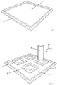
- Fig. 3 shows the situation during the production of four frame-shaped molding layers 6 on the printing plate 1.
- a print head 3 of a 3D printer is used, which as described above in connection with Fig. 1 is described.
- the print head 3 can be moved in three spatial directions x, y and z (in the plane coplanar with the printing plate 1 and perpendicular thereto) and outputs the aforementioned plastically deformable mass in such a way that individual molded body layers 6 are built up layer by layer.
- Fig. 3a shows one way in which corresponding shaped body layers or portions thereof can be applied with a forming tool.
- a template 3 ' is thereby a plastically deformable mass (not shown) through the recesses 5 by means of a doctor blade 4 in the Fig. 2 plotted illustrated printing plate 1.
- the result is a printed image, which forms a shaped body layer of the molded body to be produced.
- Fig. 4 is the correspondingly printed printing plate 1 shown.
- Fig. 7 the construction of further molded body layers 6 'is shown. These are in turn generated by the print head 3 of the 3D printer. In contrast to the shaped body layers 6 Fig. 3 are the frame-shaped shaped body layers 6 'relative to the edges of the pressure plate 1 is now rotated by approximately 45 °.
- the plastically deformable mass (not shown) is printed on the printing plate 1.
- This reprinted printing plate is now also positioned over the substrate 7, which is in the Fig. 8 is shown.
- a polymerization step can be carried out simply by applying light of the correspondingly required UV wavelength through the transparent printing plate 1 to the shaped body layers 6, 6 'to be cured.
- the molded body layers 6 'enter into compounds with the older molded body layers 6, so that the resulting molded body is essentially in one piece.
- the connections can be material-locking. It can also lead to crosslinks in certain materials.
- Fig. 9 is the support 7 now shown with four moldings, which have two levels and consist of two integrally interconnected mold body layers 6, 6 '.
- Fig. 10 For example, four moldings are shown, in which the moldings consist of a total of three moldings 6, 6 ', 6 ", each of which has been produced in one printing operation.
- a shaped body with five layer planes is shown, which consists of five shaped body layers 6 "', 6"",6""',6""", 6 """'.
- the process according to the invention is also suitable for the production of three-dimensional shaped bodies as described in US Pat WO 2014/043823 A1 are shown. These moldings have a plurality of web-shaped superposed body layers.
- the shaped body layers of the present invention may have layer thicknesses of 10 ⁇ m to 50 mm. More preferably, they have layer thicknesses of between 50 and 3000 microns.
- a shaped body according to the invention can have outside dimensions of between 1 mm and 5000 mm, in particular between 4 and 500 mm, in particular between 10 and 300 mm, in particular around 50 mm, depending on the application. These sizes are particularly suitable for the production of micromixers and catalysts. For larger components in lightweight construction, the corresponding dimensions can be larger.
- a device 11 suitable for carrying out the method according to the invention is shown schematically.
- the device 11 comprises essentially a frame having the respective guides to operate the movable parts of the device.
- a rail system serves to position a substrate 16.
- This rail system comprises an X-axis of the positioning system 12, a Y-axis of the positioning system 14 and a Z-axis of the positioning system 13.
- the substrate 16 is connected to the Z-axis of the positioning system 13 via a pivotally mounted rotary joint 15. This makes it possible for the substrate to move in all axes to take the necessary positioning in order to carry out the method according to the invention.
- a print head 3 of a 3D printer with a reservoir for the mass to be used (not shown) is about three in Fig. 12 not shown arranged on the front of the device mechanical axes (analogous to the axes 12, 13, 14), in all three spatial directions on the pressure plate (not shown) movable.
- a shaping tool can be stored in a template magazine 21.
- this template magazine 21 it is possible to prepare a number of predefined forming tools, such as templates or screens.
- a changing device takes over the moving out of the templates 22 (by way of example) via the pressure plate (not shown).
- a squeegee 18 is positioned over the template 22 to smear the corresponding mass applied from an automatic dispensing system (not shown).
- the substrate 15 can be impregnated by means of an ink pad 17 with a suitable adhesion promoter.
- the positioning system of the substrate 16 can be determined by means of a vision system consisting of camera, lens and analysis software. This system is not shown in the present description for the sake of simplicity.
- the support 16 can be lowered by means of the positioning system on the printing plate and aligned exactly.
- a UV emitter 20 can now initiate polymerization and curing through the transparent printing plate.
- the support 16 can be lifted again.
- the shaped body layer is detached from the pressure plate and forms an older shaped body layer on the substrate 16.
- This device shown here is merely shown by way of example and can be expanded with several printing plates with associated stencil changing devices for the simultaneous printing of multiple components.
Landscapes
- Engineering & Computer Science (AREA)
- Chemical & Material Sciences (AREA)
- Materials Engineering (AREA)
- Manufacturing & Machinery (AREA)
- Mechanical Engineering (AREA)
- Physics & Mathematics (AREA)
- Optics & Photonics (AREA)
Abstract
Ein Verfahren zur Herstellung von Formkörpern aus mindestens einer Formkörperschicht (6), umfassend die Schritte a) Bereitstellen eines Schichtträgers (7) zur Aufnahme mindestens einer Formkörperschicht (6); b) Erzeugen einer Formkörperschicht (6) auf einer Druckplatte (1), wobei die Formkörperschicht (6) wenigstens teilweise, insbesondere vollständig, durch ein generatives Fertigungsverfahren hergestellt wird; c) Positionieren von Druckplatte (1) und Schichtträger (7) oder älterer Formkörperschicht relativ zueinander; d) Aushärten der Formkörperschicht (6), so dass sie eine ältere Formkörperschicht bildet und Übertragen der Formkörperschicht (6); e) Eventuell Bereitstellen der Druckplatte (1) zur Aufnahme weiterer Formkörperschichten und wiederholen der Schritte b) bis d). Desweiteren eine zur Durchführung des Verfahrens geeignete Vorrichtung (11) sowie die Verwendung daraus resultierender Formkörper.A method for the production of shaped articles from at least one shaped body layer (6), comprising the steps of a) providing a layer carrier (7) for receiving at least one shaped body layer (6); b) producing a shaped body layer (6) on a printing plate (1), wherein the shaped body layer (6) is at least partially, in particular completely, produced by a generative manufacturing process; c) positioning of pressure plate (1) and layer support (7) or older shaped body layer relative to each other; d) curing the shaped body layer (6) so that it forms an older shaped body layer and transferring the shaped body layer (6); e) Possibly providing the printing plate (1) for receiving further shaped body layers and repeating steps b) to d). Furthermore, a suitable device for carrying out the method (11) and the use of resulting moldings.
Description
Die vorliegende Erfindung betrifft Verfahren zur Herstellung von Formkörpern aus mindestens einer Formkörperschicht. Sie betrifft weiter Vorrichtungen zur Herstellung eines Formkörpers aus mindestens einer Formkörperschicht sowie die Verwendung besagter Formkörper, alles gemäss den Oberbegriffen der unabhängigen Ansprüche.The present invention relates to processes for the production of moldings from at least one molding layer. It further relates to devices for producing a shaped article of at least one molding layer and the use of said moldings, all according to the preambles of the independent claims.
Beim 3-D-Druck handelt es sich um Fertigungsverfahren, um dreidimensionale Werkstücke schrittweise und automatisch aufzubauen. Üblicherweise wird beim 3-D-Druck aus einem Ausgangsmaterial eine vordefinierte Form erzeugt. Typische im 3-D-Druck verwendete Materialien sind Kunststoffe, Harze, Keramiken und Metalle. Insbesondere beim gegenwärtig sehr aktuellen Rapid-Prototyping sollen möglichst ohne manuellen Aufwand eine Vielzahl an möglichen Formen und Strukturen hergestellt werden. Dabei steht die Vielseitigkeit der druckenden Maschine im Vordergrund, um aus der formbaren Masse als Ausgangsmaterial eine vom Anwender computergestützt definierte Form strukturell und schrittweise zu replizieren. Diese Vorrichtungen und Verfahren richten sich, wie der Name schon sagt, auf die Herstellung von "Prototypen", also weitgehend Einzelstücke. Entsprechend sind die meisten Vorrichtungen und Verfahren für eine industrielle Massenfertigung ungeeignet, da sie keine grossen Umsatzzahlen aufweisen und material- und energieaufwendig sind.3-D printing is a manufacturing process used to build three-dimensional workpieces step by step and automatically. Normally, a predefined shape is generated from a starting material during 3-D printing. Typical materials used in 3-D printing are plastics, resins, ceramics and metals. In particular, in the current very rapid rapid prototyping should be produced as possible without manual effort a variety of possible shapes and structures. The focus here is on the versatility of the printing machine in order to replicate structurally and step-by-step the user-defined shape from the moldable material as the starting material. These devices and methods are, as the name implies, the production of "prototypes", ie largely individual pieces. Accordingly, most devices and methods are unsuitable for industrial mass production because they do not have high turnover and are material and energy consuming.
Es besteht somit ein Bedürfnis, Verfahren und Vorrichtungen bereitzustellen, um einen schichtweisen Aufbau dreidimensionaler Strukturen effizient und industriell skalierbar zu ermöglichen.Thus, there is a need to provide methods and apparatus to enable layered construction of three-dimensional structures efficiently and industrially scalable.
Neben dem für das Rapid Prototyping interessanten Anwendungsgebiet der Herstellung von Prototypen, Unikaten und Visualisierungen kann der 3-D-Druck verwendet werden, um industriell und technisch einsetzbare Formteile zu erstellen. In der
Ausgehend von diesem bekannten Stand der Technik und dem oben genannten Bedürfnis ist es eine Aufgabe der vorliegenden Erfindung, ein Verfahren zum schichtweisen Aufbau von Formkörpern mit mindestens einer Formkörperschicht bereitzustellen, welches besonders geeignet ist, um industriell automatisiert zu werden und insgesamt effizienter ist. Insbesondere soll ein Verfahren bereitgestellt werden, welches für die Massenproduktion geeignet ist.On the basis of this known prior art and the above-mentioned need, it is an object of the present invention to provide a process for the layered construction of moldings having at least one shaped body layer, which is particularly suitable for being industrially automated and overall more efficient. In particular, a method is to be provided which is suitable for mass production.
Die Lösung mindestens einer der genannten Aufgaben ist durch den kennzeichnenden Teil der unabhängigen Ansprüche definiert.The solution to at least one of said objects is defined by the characterizing part of the independent claims.
Ein Aspekt der vorliegenden Erfindung betrifft ein Verfahren zu Herstellung von Formkörpern aus mindestens einer Formkörperschicht. Das erfindungsgemässe Verfahren umfasst eine Reihe von Schritten. In einem ersten Schritt wird ein Schichtträger zur Aufnahme mindestens einer Formkörperschicht bereitgestellt. Eine Formkörperschicht wird auf eine Druckplatte aufgetragen, wobei die Formkörperschicht wenigstens teilweise, insbesondere vollständig, durch ein generatives Fertigungsverfahren hergestellt oder auf diese besagte Druckplatte aufgetragen wird. Grundsätzlich sei festgehalten, dass im Kontext der vorliegenden Erfindung Verfahrensschritte, welche nicht logisch zwingend aufeinanderfolgen müssen, oder bei denen eine Abfolge nicht explizit erwähnt ist, nicht ausschliesslich in der in der vorliegenden Aufzählung erfolgenden Reihenfolge ablaufen müssen. In diesem konkreten Fall kann das Bereitstellen des Schichtträgers zum Beispiel zeitgleich mit dem Auftragen der Formkörperschicht auf die Druckplatte stattfinden. Das erfindungsgemässe Verfahren umfasst weiter den Schritt, dass die Druckplatte und der Schichtträger relativ zueinander positioniert werden. Zu diesem Zeitpunkt kann auf dem Schichtträger bereits eine erste oder eine Mehrzahl älterer Formkörperschichten bestehen, die in vorgängigen Durchläufen des erfindungsgemässen Verfahrens auf diese übertragen wurden.One aspect of the present invention relates to a process for the production of moldings from at least one molding layer. The method according to the invention comprises a series of steps. In a first step, a substrate for receiving at least one molding layer is provided. A shaped body layer is applied to a printing plate, wherein the shaped body layer is at least partially, in particular completely, produced by a generative manufacturing method or applied to said printing plate. In principle, it should be noted that, in the context of the present invention, method steps which do not necessarily follow one another logically or in which a sequence is not explicitly mentioned need not be executed exclusively in the order in the present enumeration. In this specific case, the provision of the layer support, for example, take place at the same time as the application of the shaped body layer to the printing plate. The inventive method further comprises the step that the pressure plate and the substrate are positioned relative to each other. At this time, a first or a plurality of older shaped-body layers, which have been transferred to them in previous passes of the method according to the invention, may already be present on the substrate.
Grundsätzlich kann das erfindungsgemässe Verfahren mit einer einzigen Druckplatte durchgeführt werden. Es ist aber auch möglich, mehrere unterschiedliche Druckplatten zu verwenden, welche insbesondere simultan, nacheinander und/oder alternierend eingesetzt werden. Damit kann unter Umständen das Verfahren beschleunigt oder die Herstellung von komplexen Strukturen vereinfacht werden.In principle, the method according to the invention can be carried out with a single printing plate. But it is also possible to use several different printing plates, which are used in particular simultaneously, sequentially and / or alternately. This may speed up the process or simplify the production of complex structures.
Im Sinne der vorliegenden Erfindung kann unter dem relativen Positionieren der Druckplatte verstanden werden, dass entweder die Druckplatte oder der Schichtträger oder beide eine Bewegung vollführen, bei der die Formkörperschicht auf der Druckplatte mit entweder dem Schichtträger oder einer allfällig darauf bereits vorhandenen älteren Formkörperschicht kontaktiert wird. Dabei werden bevorzugt Druckplatte und Schichtträger relativ zueinander so positioniert, dass die Formkörperschicht beim Übertrag von der Druckplatte auf den Schichtträger exakt wie gewünscht auf dem Schichtträger ausgerichtet ist.For the purposes of the present invention, the relative positioning of the printing plate can be understood as meaning that either the printing plate or the substrate or both perform a movement in which the molding layer is contacted on the printing plate with either the substrate or any older molding layer already thereon. In this case, printing plate and substrate are preferably positioned relative to each other so that the shaped body layer is exactly aligned as desired on the substrate during transfer from the printing plate to the substrate.
In einem weiteren Schritt wird die Formkörperschicht ausgehärtet. Eine ausgehärtete Formkörperschicht wird im Kontext des erfindungsgemässen Verfahrens eine ältere Formkörperschicht oder geht mit einer bereits bestehenden älteren Formkörperschicht einen Verbund ein. Dieser Aushärtungsschritt kann insbesondere zu dem Zeitpunkt stattfinden, in dem die Druckplatte und der Schichtträger relativ zueinander positioniert sind. In diesem Zustand können Schichtträger und Druckplatte mechanische Stützen für die noch nicht ausgehärtete Formkörperschicht bilden.In a further step, the shaped body layer is cured. In the context of the method according to the invention, a hardened shaped body layer becomes an older shaped body layer or merges with an already existing older shaped body layer. This curing step may take place in particular at the time when the pressure plate and the substrate are positioned relative to each other. In this state, the substrate and printing plate can form mechanical supports for the as yet uncured molded body layer.
Entsprechend kann die Formkörperschicht des aktuellen Verfahrensschrittes auf eine oder mehrere ältere Formkörperschicht(en) übertragen werden, wobei entsprechend die Druckplatte oder die älter(en) Formkörperschicht(en) relativ zueinander positioniert sind. Ein Übertragen der Formkörperschicht beinhaltet ein Ablösen von der Druckplatte. Für spätere Durchläufe wird die gehärtete, übertragene Formkörperschicht somit zu einer älteren Formkörperschicht. Im Sinne der vorliegenden Erfindung ist eine ältere Formkörperschicht im Verhältnis zur aktuellen Formkörperschicht definiert. Das heisst, jede einer Formkörperschicht vorangegangene Formkörperschicht ist bezüglich dieser eine ältere Formkörperschicht. Alternativ können die Formkörperschichten bezüglich ihrer Anzahl durchnummeriert werden. So ist die erste auf einem Schichtträger übertragene Formkörperschicht die erste Formkörperschicht. Die zweite Formkörperschicht entsprechend die zweite, usw. Selbstredend wäre die erste Formkörperschicht bezüglich der zweiten die ältere Formkörperschicht. Die Anzahl durchlaufener Wiederholungen ist abhängig von der gewünschten Endform des resultierenden Formkörpers und kann vom Fachmann individuell gewählt werden. Entsprechend umfasst der letzte Schritt des erfindungsgemässen Verfahrens das eventuelle Bereitstellen der Druckplatte zur Aufnahme weiterer Formkörperschichten und das anschliessende Wiederholen der oben genannten Verfahrensschritte. In einer besonderen Ausführungsform ist eine ältere Formkörperschicht zugleich eine gehärtete Formkörperschicht.Accordingly, the shaped body layer of the current process step can be transferred to one or more older shaped body layer (s), wherein correspondingly the pressure plate or the older (s) shaped body layer (s) are positioned relative to each other. Transferring the shaped body layer involves peeling off the printing plate. For later runs, the cured, transferred shaped body layer thus becomes an older shaped body layer. For the purposes of the present invention, an older shaped body layer is defined in relation to the current shaped body layer. That is, each mold body layer preceding a mold body layer is an older mold body layer with respect to it. Alternatively, the shaped body layers can be numbered by number. So the first is transmitted on a support Shaped body layer, the first shaped body layer. The second molded body layer corresponding to the second, etc. Of course, the first mold body layer with respect to the second would be the older mold body layer. The number of repetitions passed depends on the desired final shape of the resulting molded article and can be selected individually by the person skilled in the art. Correspondingly, the last step of the method according to the invention comprises the eventual provision of the printing plate for receiving further shaped body layers and the subsequent repeating of the abovementioned method steps. In a particular embodiment, an older shaped-body layer is at the same time a hardened shaped-body layer.
Im Sinne der vorliegenden Erfindung ist der aus dem erfindungsgemässen Verfahren resultierende Formkörper insofern aus mindestens einer Formkörperschicht aufgebaut, als dass diese ein direktes Resultat aus dem Verfahren ist. Grundsätzlich sind die resultierenden Formkörper aber nicht auf die nach Abschluss des Prozesses bedingte Erkennbarkeit der einzelnen Formkörperschichten beschränkt. Auch sind die resultierenden Formkörper nicht auf rechtwinklige, flache Schichten oder Schichten homogener Dicke beschränkt.In the context of the present invention, the shaped body resulting from the method according to the invention is constructed from at least one shaped body layer in that it is a direct result of the method. In principle, however, the resulting shaped bodies are not limited to the recognizability of the individual shaped body layers that is conditional upon conclusion of the process. Also, the resulting molded articles are not limited to rectangular, flat layers or layers of homogeneous thickness.
Mit dem erfindungsgemässen Verfahren können Formkörperschichten oder Teile davon rasch automatisiert aufgebaut und aufgetragen werden. Dadurch eignet sich das erfindungsgemässe Verfahren besonders gut für die Massenproduktion.By means of the process according to the invention, shaped body layers or parts thereof can be quickly built up and applied automatically. As a result, the method according to the invention is particularly suitable for mass production.
Der Begriff "generatives Fertigungsverfahren" bzw. "generative Fertigung" bezeichnet Verfahren, bei welchen durch gezielte räumliche Ablagerung, Aufbringung und/oder Verfestigung von Material ein räumliches Objekt erzeugt wird. Vorliegend besteht das räumliche Objekt aus einer Formkörperschicht. Die Ablagerung, Aufbringung und/oder Verfestigung des Materials erfolgt dabei insbesondere anhand eines Datenmodells des zu erzeugenden Objekts oder der Formkörperschicht und insbesondere lageweise. Jede einzelne Formkörperschicht kann somit im generativen Fertigungsverfahren aus einer oder mehreren Lagen hergestellt werden. Üblicherweise wird zur Fertigung eines Objekts oder einer Formkörperschicht ein formloses Material (z.B. aus Flüssigkeiten, Pulver, Granulate, etc.) und/oder ein formneutrales Material (z.B. Bänder, Drähte) verwendet, welches insbesondere chemischen und/oder physikalischen Prozessen (z.B. Schmelzen, Polymerisieren, Sintern) unterzogen wird. Generative Fertigungsverfahren sind dem Fachmann an sich bekannt und werden unter anderem auch als "Additive Fertigungsverfahren" oder "Additive Manufacturing" bezeichnet.The term "generative manufacturing process" or "additive manufacturing" refers to processes in which a spatial object is generated by targeted spatial deposition, application and / or solidification of material. In the present case, the spatial object consists of a shaped body layer. The deposition, application and / or solidification of the material takes place, in particular, on the basis of a data model of the object to be produced or the shaped body layer and, in particular, in layers. Each individual shaped body layer can thus be produced in the additive manufacturing process from one or more layers. Usually, an informal material (eg from liquids, powders, granules, etc.) and / or a form-neutral material (eg ribbons, wires) is used for the production of an object or a shaped body layer, which in particular chemical and / or physical processes (eg melting, Polymerizing, sintering). Generative manufacturing processes are known per se to those skilled in the art and are also referred to inter alia as "additive manufacturing processes" or "additive manufacturing".
Insbesondere handelt es sich beim generativen Fertigungsverfahren um ein werkzeuglos und/oder formlos durchgeführtes Verfahren. Im Besonderen wird für das generative Fertigungsverfahren keine Gussform und/oder kein formgebendes Werkzeug verwendet.In particular, the additive manufacturing process is a tool-free and / or informal process. In particular, no mold and / or molding tool is used for the additive manufacturing process.
Grundsätzlich kann es sich beim generativen Fertigungsverfahren insbesondere um ein Pulverbettverfahren, ein Freiraumverfahren und/oder ein Flüssigmaterialverfahren handeln.In principle, the generative production method may in particular be a powder bed process, a free-space process and / or a liquid material process.
Bei den Pulverbettverfahren wird das zu verarbeitende Material in Pulverform in einer dünnen Schicht auf einer Grundplatte oder Druckplatte aufgebracht. Das zu verarbeitende Material wird sodann lokal verfestigt, insbesondere lageweise, so dass das zu erzeugende Objekt oder die Formkörperschicht generiert wird. Überschüssiges und nicht verfestigtes Pulver wird entfernt. Die Verfestigung des Pulvers kann durch gezielten lokalen Energieeintrag, z.B. mit einer elektromagnetischen Strahlungsquelle (beispielsweise einem Laser) oder einer Elektronenstrahlquelle, erreicht werden. Bekannt sind z.B. folgende Verfahren: selektives Laserschmelzen, Lasersintern, Elektronenstrahlschmelzen.In the powder bed process, the material to be processed is applied in powder form in a thin layer on a base plate or printing plate. The material to be processed is then solidified locally, in particular in layers, so that the object to be produced or the shaped body layer is generated. Excess and unconsolidated powder is removed. The solidification of the powder can be achieved by targeted local energy input, e.g. with an electromagnetic radiation source (for example a laser) or an electron beam source. It is known e.g. following methods: selective laser melting, laser sintering, electron beam melting.
Auch möglich ist es, die Verfestigung durch gezielte lokale Einbringung eines chemischen Reaktanden, z.B. ein Bindemittel, in das Pulverbett zu bewirken. Bei Verwendung eines Bindemittels wird das Pulvermaterial an den ausgewählten Stellen mit dem Bindemittel verklebt und dadurch verfestigt. Dies wird auch als Binder Jetting bezeichnet.It is also possible to use solidification by targeted local introduction of a chemical reactant, e.g. a binder to effect into the powder bed. When using a binder, the powder material is bonded at the selected locations with the binder and thereby solidified. This is also called binder jetting.
Im Besonderen handelt es sich beim Pulverbettverfahren um selektives Laserschmelzen, Lasersintern, Elektronenstrahlschmelzen und/oder Binder Jetting. Beim Flüssigmaterialverfahren liegt das zu verarbeitende Material in flüssiger Form vor. Die Verfestigung erfolgt typischerweise durch gezielten lokalen Energieeintrag in die Flüssigkeit. Beispielsweise wird ein lichtaushärtendes Material von einem Laserstrahl gezielt lokal ausgehärtet. Als lichtaushärtendes Material werden z.B. Kunststoffe, insbesondere Photopolymere, wie zum Beispiel Acryl-, Epoxid- und/oder Vinylesterharze, eingesetzt. Insbesondere handelt es sich beim Flüssigmaterialverfahren um ein Stereolithographieverfahren.In particular, the powder bed process is selective laser melting, laser sintering, electron beam melting and / or binder jetting. In the liquid material process, the material to be processed is in liquid form. The solidification is typically carried out by targeted local energy input into the liquid. For example, a light-curing material is selectively locally cured by a laser beam. As light-curing material, for example, plastics, in particular photopolymers, such as acrylic, epoxy and / or vinyl ester resins, used. In particular, the liquid material method is a stereolithography method.
Bei Freiraumverfahren wird das zu verarbeitende Material ausschließlich an solchen Stellen aufgebracht, wo das zu erzeugende Objekt oder die Formkörperschicht entstehen soll. Im Gegensatz zum Pulververfahren wird beim Freiraumverfahren somit nicht der komplette Bauraum mit zu verarbeitendem Material gefüllt. Das zu verarbeitende Material liegt als Rohmaterial insbesondere in einer festen Form, z.B. als Pulver, Filament und/oder Granulat vor. Auch möglich ist es, dass das zu verarbeitende Material in flüssiger Form vorliegt. Als Freiraumverfahren bekannt sind z.B. Schmelzschichtverfahren ("Fused Deposition Modeling") oder Extrusionsverfahren. Bei Schmelzschichtverfahren wird das zu verarbeitende Material, z.B. als Strang, durch eine Heizdüse gefördert und dabei soweit erhitzt, dass es schmilzt und durch die Düse extrudiert werden kann. Beim Extrusionsverfahren wird das zu verarbeitende Material, insbesondere eine plastisch verformbaren Masse, z.B. eine Paste, durch eine Düse ausgetragen und in einem nachfolgenden Schritt verfestigt und/oder ausgehärtet. Dabei kann auch auf eine Erhitzung verzichtet werden.In free space method, the material to be processed is applied only at those points where the object to be generated or the shaped body layer is to arise. In contrast to the powder method, the free space method therefore does not fill the entire installation space with material to be processed. The material to be processed is present as a raw material, in particular in a solid form, e.g. as a powder, filament and / or granules. It is also possible that the material to be processed is in liquid form. As open space methods are known e.g. Fused Deposition Modeling or extrusion process. In melt-layer processes, the material to be processed, e.g. as a strand, conveyed through a heating nozzle and heated to the extent that it melts and can be extruded through the nozzle. In the extrusion process, the material to be processed, in particular a plastically deformable mass, e.g. a paste, discharged through a nozzle and solidified and / or cured in a subsequent step. It can also be dispensed with a heating.
Mit Vorteil ist das generative Fertigungsverfahren ein Freiraumverfahren, insbesondere ein Schmelzschichtungsverfahren und/oder ein Extrusionsverfahren. Besonders bevorzugt sind Extrusionsverfahren. Diese Verfahren haben sich in Kombination mit den weiteren Verfahrensschritten des erfindungsgemässen Verfahrens als besonders geeignet herausgestellt. Zudem haben sie den Vorteil, dass nur diejenige Menge an zu verarbeitendem Material eingesetzt werden muss, welche für die Erzeugung des Objekts notwendig ist und keine Entfernung von überschüssigem Material, z.B. Pulver oder Flüssigkeit, erforderlich ist.Advantageously, the additive manufacturing process is a free-space process, in particular a melt-coating process and / or an extrusion process. Particularly preferred are extrusion processes. These processes have proven to be particularly suitable in combination with the further process steps of the process according to the invention. In addition, they have the advantage that only the amount of material to be processed which is necessary for the production of the object and no removal of excess material, e.g. Powder or liquid, is required.
Insbesondere wird die Formkörperschicht auf der Druckplatte aus einer plastisch verformbaren Masse, insbesondere einer Paste, erzeugt. Mit anderen Worten wird im generativen Verfahren als zu verarbeitendes Material insbesondere eine plastisch verformbare Masse, im Speziellen eine Paste, eingesetzt. Derartige Pasten können insbesondere auch ohne Erhitzung verarbeitet werden und weisen bereits eine gewisse Formstabilität nach dem Auftragen auf. Nähere Angaben zu den plastischen Massen finden sich weiter unten. Es sind aber grundsätzlich auch nicht plastisch verformbare Materialen einsetzbar.In particular, the shaped body layer is produced on the pressure plate from a plastically deformable mass, in particular a paste. In other words, in the generative process, in particular a plastically deformable mass, in particular a paste, is used as the material to be processed. Such pastes can be processed in particular without heating and already have a certain dimensional stability after application. Find more information about the plastic masses down below. However, in principle it is also not possible to use plastically deformable materials.
Besonders bevorzugt wird das generative Fertigungsverfahren mit einem in wenigstens zwei Raumdimensionen, insbesondere drei Raumdimensionen, bewegbaren Austragungsvorrichtung, im Besonderem einem bewegbaren Druckkopf, durchgeführt. Die Austragungsvorrichtung kann auch als Dispenser bezeichnet werden.Particularly preferably, the generative manufacturing method with a in at least two spatial dimensions, in particular three room dimensions, movable discharge device, in particular a movable printhead performed. The dispensing device may also be referred to as a dispenser.
Die verwendete Austragungsvorrichtung ist dabei insbesondere in einer zur Druckplatte coplanaren Ebene bewegbar. Optional kann die Druckplatte dabei in einer Richtung senkrecht zur Ebene der Druckplatte bewegbar ausgestaltet werden. Damit können nahezu beliebige Objekte oder Formkörperschichten auf der Druckplatte hergestellt werden. In einer weiteren bevorzugten Ausführungsform ist die Austragungsvorrichtung zusätzlich in einer Richtung senkrecht zur Ebene der Druckplatte bewegbar. Durch derartig bewegbare Austragungsvorrichtungen können auf der Druckplatte nahezu beliebig geformte Objekte ausgebildet werden.The dispensing device used is movable in particular in a coplanar plane to the printing plate. Optionally, the pressure plate can be designed to be movable in a direction perpendicular to the plane of the pressure plate. This allows almost any objects or mold layers to be produced on the printing plate. In a further preferred embodiment, the discharge device is additionally movable in a direction perpendicular to the plane of the printing plate. By such movable discharge devices can be formed on the printing plate almost arbitrarily shaped objects.
Die verwendete Austragungsvorrichtung umfasst insbesondere wenigstens eine Düse zum Austragen des zu verarbeitenden Materials, insbesondere einer plastisch verformbaren Masse. Gemäss einer weiteren vorteilhaften Ausführungsform umfasst die im Verfahren verwendete Austragungsvorrichtung mehrere, insbesondere 2 - 256 oder 32 - 128, individuell adressierbare und/oder individuell bewegbare Düsen. Damit kann die Herstellung der Formkörperschicht weiter beschleunigt werden.The discharge device used in particular comprises at least one nozzle for discharging the material to be processed, in particular a plastically deformable mass. According to a further advantageous embodiment, the dispensing device used in the method comprises a plurality of, in particular 2 - 256 or 32 - 128, individually addressable and / or individually movable nozzles. Thus, the production of the shaped body layer can be further accelerated.
Die Austragungsvorrichtung ist im Besonderen so ausgestaltet, dass sie das auszutragende Material in einzelnen Tropfen mit einem Volumen von 0.1 - 100 pL, insbesondere 1 - 50 pL, austragen kann.The discharge device is in particular designed such that it can discharge the material to be discharged in individual drops having a volume of 0.1-100 pL, in particular 1-50 pL.
Die Austragungsvorrichtung verfügt mit Vorteil über einen Temperaturkontroller mit welchem eine Temperatur des auszutragenden Materials und/oder einer Düse kontrolliert werden kann.The discharge device advantageously has a temperature controller with which a temperature of the material to be discharged and / or a nozzle can be controlled.
Besonders bevorzugt handelt es sich bei der Austragungsvorrichtung um einen Tintenstrahldrucker, einen Plotter, einen 2D-Drucker und/oder um einen 3D-Drucker.Particularly preferably, the discharge device is an inkjet printer, a plotter, a 2D printer and / or a 3D printer.
Im Besonderen weist das zu verarbeitende Material oder die plastisch verformbare Masse eine Viskosität von 10 - 106 mPa·s, bevorzugt 100 - 105 mPa·s auf. Viskositäten werden im vorliegenden Zusammenhang insbesondere bei 25°C bestimmt, bevorzugt nach der Brookfield-Methode und im Besonderen nach DIN EN ISO 2555:2000-01.In particular, the material to be processed or the plastically deformable mass has a viscosity of 10 - 10 6 mPa · s, preferably 100 - 10 5 mPa · s. Viscosities are determined in the present context, in particular at 25 ° C, preferably according to the Brookfield method and in particular according to DIN EN ISO 2555: 2000-01.
Gemäss einer weiteren vorteilhaften Ausführungsform wird das zu verarbeitende Material, insbesondere eine plastisch verformbare Masse, vor Schritt b) mit einem Lösungsmittel, insbesondere Wasser, verdünnt. Dies mit Vorteil so, dass eine Viskosität des verdünnten zu verarbeitenden Materials oder der plastisch verformbaren Masse reduziert wird, im Besonderen so dass die Viskosität im Bereich von 10 - 106 mPa·s, bevorzugt 100 - 105 mPa·s, liegt. Damit kann die Austragung des zu verarbeitenden Materials durch vorstehend genannte Austragungsvorrichtungen erleichtert werden.According to a further advantageous embodiment, the material to be processed, in particular a plastically deformable mass, before step b) with a solvent, in particular water, diluted. This advantageously so that a viscosity of the diluted material to be processed or the plastically deformable mass is reduced, in particular so that the viscosity in the range of 10 - 10 6 mPa · s, preferably 100 - 10 5 mPa · s, is. Thus, the discharge of the material to be processed by the above-mentioned Austragungsvorrichtungen be facilitated.
Das Lösungsmittel wird mit Vorteil auf die chemische Zusammensetzung des zu verarbeitenden Materials, insbesondere der plastisch verformbaren Masse, abgestimmt. Im Besonderen handelt es sich aber um Wasser, Alkohole, z.B. Ethanol, und/oder organische Lösungsmittel.The solvent is advantageously matched to the chemical composition of the material to be processed, in particular the plastically deformable mass. In particular, however, it is water, alcohols, e.g. Ethanol, and / or organic solvents.
In einer besonderen Ausführungsform wird das zu verarbeitende Material, insbesondere die plastisch verformbare Masse, nach erfolgter Austragung mit der Austragungsvorrichtung während und/oder nach Schritt b), einem Trocknungsprozess unterzogen. Der Trocknungsprozess erfolgt dabei mit Vorteil noch vor Schritt c). Unter einem Trocknungsprozess ist ein Verfahren zu verstehen, bei welchem ein Anteil an Lösungsmittel und/oder von anderen flüssigen Bestandteilen in der plastisch verformbaren Masse reduziert wird. Damit kann insbesondere ein Verlaufen von dünnflüssigem und/oder vorgängig verdünntem zu verarbeitendem Material, insbesondere plastisch verformbarer Masse, verhindert werden.In a particular embodiment, the material to be processed, in particular the plastically deformable mass, is subjected to a drying process after discharge with the discharge device during and / or after step b). The drying process takes place with advantage before step c). A drying process is a process in which a proportion of solvent and / or other liquid constituents in the plastically deformable mass is reduced. In particular, bleeding of low-viscosity and / or previously diluted material to be processed, in particular plastically deformable mass, can thus be prevented.
In einer anderen vorteilhaften Ausführungsform wird die Formkörperschicht in Schritt b) teilweise durch ein generatives Fertigungsverfahren und teilweise durch ein formgebendes Werkzeug auf die Druckplatte aufgetragen. Dadurch können beispielsweise unterschiedliche Bereiche einer Formkörperschicht durch eine optimale auf die Struktur im jeweiligen Bereich angepasste Methode und/oder aus unterschiedlichen Materialen erzeugt werden. So können beispielsweise komplexe Strukturelemente einer Formkörperschicht durch das generative Verfahren erzeugt werden, während einfachere Elemente durch das formgebende Werkzeug aufgebracht werden. Dies kann der Effizienz des Verfahrens insgesamt zu Gute kommen.In another advantageous embodiment, the shaped body layer is applied in step b) partly by a generative manufacturing process and partly by a shaping tool on the printing plate. As a result, for example, different regions of a shaped body layer can be produced by an optimum method adapted to the structure in the respective region and / or from different materials. For example, complex structural elements of a Shaped body layer are generated by the generative process, while simpler elements are applied by the forming tool. This can benefit the overall efficiency of the process.
Auch kann es Vorteilhaft sein, wenn das erfindungsgemässe Verfahren zusätzlich einen weiteren Schritt b') umfasst, bei welchem eine Formkörperschicht durch ein formgebendes Werkzeug auf die Druckplatte aufgetragen wird. Schritt b') kann dabei vor und/oder nach einer ersten Durchführung der Schritte a) bis d) erfolgen, zum Beispiel in der Schrittabfolge a), b'), c) und d). Dadurch können einzelne Formkörperschichten gänzlich durch ein formgebendes Werkzeug hergestellt werden. Auch diese Massnahme kann je nach herzustellender Struktur dazu beitragen, das Verfahren insgesamt zu beschleunigen.It may also be advantageous if the method according to the invention additionally comprises a further step b '), in which a shaped body layer is applied to the printing plate by means of a shaping tool. Step b ') can take place before and / or after a first execution of steps a) to d), for example in the step sequence a), b'), c) and d). As a result, individual shaped body layers can be produced entirely by a shaping tool. Depending on the structure to be produced, this measure can also contribute to speeding up the process as a whole.
In einer besonderen Ausführungsform des erfindungsgemässen Verfahrens ist das formgebende Werkzeug, falls eingesetzt, eine Schablone. Die Schablone kann so ausgestaltet sein, dass sie als ebene Fläche über der Druckplatte positionierbar ist. Ausnehmungen in der Schablone definieren die Form der durch die entsprechenden Schablonen aufgetragenen Formkörperschicht und/oder die Form von Teilbereichen der Formkörperschicht. Eine Schablone oder ein formgebendes Werkzeug kann eine Vielzahl identischer oder unterschiedlicher Formen für Formkörperschichten und/oder Teilbereiche von Formkörperschichten definieren.In a particular embodiment of the method according to the invention, the forming tool, if used, is a template. The template can be designed so that it can be positioned as a flat surface over the printing plate. Recesses in the stencil define the shape of the shaped body layer applied by the respective stencils and / or the shape of partial regions of the shaped body layer. A stencil or forming tool can define a variety of identical or different shapes for shaped body layers and / or subregions of shaped body layers.
In einer besonderen Ausführungsform ist das formgebende Werkzeug ein Sieb, insbesondere ein Sieb für den technischen Siebdruck.In a particular embodiment, the forming tool is a sieve, in particular a sieve for technical screen printing.
Ein weiterer Vorteil des erfindungsgemässen Verfahrens ist, dass der Schritt des Auftragens der Formkörperschicht auf den Schichtträger indirekt erfolgt, das heisst, dass zunächst von einer Druckerplatte die Formkörperschicht mit bereits definierter Form auf den Schichtträger übertragen wird. Dank dieses indirekten Druckverfahrens kann im vorliegenden Verfahren auch eine Kombination aus generativen Fertigungsverfahren und Druckverfahren mit formgebenden Werkzeugen, z.B. Sieb- und Schablonendruck, angewandt werden.A further advantage of the method according to the invention is that the step of applying the shaped body layer to the substrate is carried out indirectly, that is to say that first of all the shaped body layer with already defined shape is transferred onto the substrate from a printing plate. Thanks to this indirect printing process, the present process may also involve a combination of additive manufacturing processes and printing processes with forming tools, e.g. Screen and stencil printing.
In einer besonderen Ausführungsform ist die Druckplatte eben ausgestaltet. Dies vereinfacht den Aufbau von Formkörperschichten im Allgemeinen. Werden die Formkörperschichten oder Teile davon mit einem zusätzlichen formgebenden Werkzeug hergestellt, hat dies den weiteren Vorteil, dass besonders für Schablonendruck eine perfekt ebene Unterlage besonders gute Druckresultate bei den einzelnen Formkörperschichten liefert. Aber auch beim Siebdruck ist eine ebene Druckplatte von Vorteil für das Druckresultat der einzelnen Formkörperschichten.In a particular embodiment, the pressure plate is configured just. This simplifies the construction of moldings in general. Will the Molded body layers or parts thereof produced with an additional shaping tool, this has the further advantage that, especially for stencil printing a perfectly flat surface provides particularly good results in printing the individual moldings layers. But even with screen printing, a flat printing plate is advantageous for the printing result of the individual shaped body layers.
Ohne an diese Theorie gebunden zu sein, scheint einer der erfindungsgemässen Vorteile darin zu liegen, dass die Druckplatte den Formkörperschichten zusätzlichen Halt gibt, bis sie ausgehärtet sind. Dadurch ist es möglich, komplexere Muster zu drucken, die nicht vollständig auf älteren Formkörperschichten aufliegen müssen.Without being bound by this theory, one of the advantages according to the invention appears to lie in the fact that the pressure plate gives the shaped body layers additional support until they have hardened. This makes it possible to print more complex patterns that do not have to rest completely on older moldings.
In einer besonderen Ausführungsform ist die Druckplatte so ausgestaltet, dass die Formkörperschicht darauf schlecht haftet. Die Formkörperschicht wird von der Druckplatte auf den Schichtträger oder die ältere Formkörperschicht übertragen. Um die Übertragung zu erleichtern ist es von Vorteil, wenn die Formkörperschicht nicht übermässig an der Druckplatte haftet. Die Haftung einer ausgehärteten Paste auf einer Oberfläche hängt von der Oberflächenform sowie von der Paarung Oberfläche - Paste ab. Für geringe Haftung muss eine chemische Verbindung der Paste mit der Oberfläche ausgeschlossen werden, die Struktur der Oberfläche glatt sein und die Oberfläche eine möglichst niedrige Oberflächenenergie aufweisen. Oberflächenenergien kleiner als 40 mN/m, insbesondere Oberflächenenergien kleiner als 30 mN/m und insbesondere Oberflächenenergien kleiner als 20 mN/m gelten im Sinne der vorliegenden Anmeldung als niedrig.In a particular embodiment, the pressure plate is designed such that the shaped body layer adheres poorly thereto. The shaped body layer is transferred from the printing plate to the support or the older shaped body layer. In order to facilitate the transfer, it is advantageous if the shaped body layer does not adhere excessively to the printing plate. The adhesion of a cured paste to a surface depends on the surface shape as well as on the mating surface - paste. For low adhesion, a chemical compound of the paste with the surface must be excluded, the structure of the surface should be smooth and the surface should have the lowest possible surface energy. Surface energies of less than 40 mN / m, in particular surface energies of less than 30 mN / m, and in particular surface energies of less than 20 mN / m, are considered low for the purposes of the present application.
In einer besonderen Ausführungsform ist das Material der Druckplatte so ausgestaltet, dass die Formkörperschicht darauf schlecht haftet. Zusätzlich oder in einer alternativen Ausführungsform kann die Oberfläche der Druckplatte dergestalt bearbeitet sein, dass sich die Formkörperschicht im entsprechenden Übertragungsschritt leicht ablöst. Grundsätzlich ist dies durch eine Oberflächenbehandlung der Druckplatte möglich. Diese Oberflächenbehandlung kann permanent sein, das heisst, die Druckplatte ist mit einer entsprechenden Oberflächenbehandlung versehen, die bereits im Fertigungsprozess der Druckplatte stattgefunden hat. Alternativ oder zusätzlich kann die Druckplatte mit einem temporären System der Oberflächenbehandlung ausgestattet sein. Es ist zum Beispiel möglich, die Druckplatte mit einem Wachs oder Harz oder einem Pulver zu beschichten, welches sich im Verlauf der Anwendungen der Druckplatte verbraucht und wiederholt aufgetragen werden muss. Entsprechend können in einer Vorrichtung zur Durchführung des erfindungsgemässen Verfahrens Strukturen vorgesehen sein, welche diese Beschichtung jeweils in periodischen Abständen oder vor jeder Anwendung der Druckplatte vornehmen.In a particular embodiment, the material of the printing plate is designed such that the shaped body layer adheres poorly thereto. Additionally or in an alternative embodiment, the surface of the printing plate may be processed such that the shaped body layer easily peels off in the corresponding transfer step. Basically, this is possible by a surface treatment of the printing plate. This surface treatment can be permanent, that is, the printing plate is provided with a corresponding surface treatment that has already taken place in the production process of the printing plate. Alternatively or additionally, the printing plate may be equipped with a temporary system of surface treatment. It is for example it is possible to coat the printing plate with a wax or resin or a powder, which is consumed in the course of the applications of the printing plate and must be applied repeatedly. Accordingly, in an apparatus for carrying out the method according to the invention, structures may be provided which perform this coating at periodic intervals or before each application of the printing plate.
In einer besonderen Ausführungsform ist das Haftverhalten der Druckplatte mittels Einbrennsilikonisierung gesenkt. In einer alternativen besonderen Ausführungsform ist die Druckplatte mit einer Beschichtung, welche Fluorpolymere enthält, versehen.In a particular embodiment, the adhesion of the printing plate is lowered by means of Einbrennsilikonisierung. In an alternative particular embodiment, the printing plate is provided with a coating containing fluoropolymers.
In einer besonderen Ausführungsform ist das Haftverhalten der Druckplatte mittels einer Schicht Polydimethylsiloxan oder anderer Polysilane gesenkt.In a particular embodiment, the adhesion of the printing plate is lowered by means of a layer of polydimethylsiloxane or other polysilanes.
In einer besonderen Ausführungsform wird vor jeder Anwendung eine dünne Beschichtung auf die Druckplatte aufgebracht. In einer bevorzugten Ausführungsform werden fett- oder wachshaltige Schichten vor jeder Anwendung auf die Druckplatte aufgebracht.In a particular embodiment, a thin coating is applied to the printing plate prior to each use. In a preferred embodiment, layers containing fat or wax are applied to the printing plate before each application.
Alternativ können auch Trockenschmiermittel oder Trockengleitschichten, wie sie aus der Trockenschmierung von Gleitlagern bekannt sind, verwendet werden, um die Hafteigenschaften der Druckplatte zu senken. Bevorzugt sind transparente Trockengleitschichten basierend auf synthetischen Wachsen.Alternatively, dry lubricants or dry lubricating layers, as known from dry lubrication of plain bearings, can be used to lower the adhesive properties of the printing plate. Transparent dry sliding layers based on synthetic waxes are preferred.
In einer besonderen Ausführungsform werden thermisch behandelte Silikatschichten verwendet. Wasserlösliche Natronsilikate, Lithiumsilikate oder Kaliumsilikate können in flüssiger Form aufgetragen werden und erstarren beim Trocknen zu glasartigen, amorphen Schichten. Besonders wenn Pasten mit Acrylbasierten Photopolymeren zur Bildung der Formkörperschichten verwendet werden, hat es sich überraschend gezeigt, dass eine Beschichtung der Druckplatte mit einer dünnen Schicht Natronsilikat, welche vor dem Einsatz in einem Ofen für eine halbe Stunde auf rund 100°C erhitzt wird, besonders gute Ergebnisse liefert.In a particular embodiment, thermally treated silicate layers are used. Water-soluble sodium silicates, lithium silicates or potassium silicates can be applied in liquid form and solidify on drying to glassy, amorphous layers. Particularly when pastes with acrylic-based photopolymers are used to form the shaped body layers, it has surprisingly been found that a coating of the printing plate with a thin layer of sodium silicate, which is heated to about 100 ° C for half an hour prior to use in an oven, is particularly gives good results.
In einer besonderen Ausführungsform wird die ältere Formkörperschicht auf dem Schichtträger oder der Schichtträger selbst in einem Verfahrensschritt mit einem Haftvermittler versehen, bevor eine nächste weitere Formkörperschicht darauf übertragen wird. Bevorzugt umfasst dieser Schritt ein Eintunken, Besprühen oder Benetzen mittels eines Stempelkissens des Schichtträgers mit besagtem Haftvermittler.In a particular embodiment, the older shaped-body layer on the support or the support itself is provided with a bonding agent in one process step before a next further molding-body layer is transferred thereon becomes. This step preferably comprises dipping, spraying or wetting by means of an ink pad of the substrate with said adhesion promoter.
Ein Haftvermittler kann dazu führen, dass die Verbindung zwischen der aktuellen Formkörperschicht und der älteren Formkörperschicht verbessert wird. Dazu wird die Stirnfläche der älteren Formkörperschicht, welche bereits ausgehärtet ist, zum Beispiel mit einem dünnflüssigen Haftvermittler benetzt. Je nach verwendetem Material können verschiedene Haftvermittler eingesetzt werden. Insbesondere bei Pasten die auf Photopolymeren basieren können zum Beispiel Monomere ohne Photoinitiator verwendet werden, die nur im Kontakt mit den Pasten vernetzen, die den entsprechenden Photoinitiator enthalten. Wo die neue Formkörperschicht die ältere schon ausgehärtete Formkörperschicht nicht berührt, bleibt dieser Haftvermittler auch unter der Wirkung der UV Strahlung flüssig. Bei Acryl-basierten Photopolymeren und deren dünnflüssigen Monomeren können alternativ auch dem als Haftvermittler eingesetzten Monomer Photoinitiatoren beigemischt werden. Die dünnen Monomerschichten härten in diesem Fall nicht aus, wenn sie nicht durch die Paste der neuen Formkörperschicht überdeckt werden, da bei den sehr dünnen Haftvermittlerschichten die Polymerisation durch den Sauerstoff in der Luft inhibiert wird. In einer besonderen Ausführungsform des erfindungsgemässen Verfahrens wird ein zu verarbeitendes Material, insbesondere eine plastisch verformbare Masse, durch die Ausnehmungen des formgebenden Werkzeugs auf die Druckplatte zur Bildung der Formkörperschicht oder Teilbereichen davon aufgetragen. Geeignete zu verarbeitende Materialien, insbesondere plastisch verformbare Massen, können vom Fachmann je nach gewünschtem Anwendungsgebiet, dem anvisierten Härtungsprozess und der Materialverfügbarkeit gewählt werden.An adhesion promoter can lead to the connection between the current shaped body layer and the older shaped body layer being improved. For this purpose, the end face of the older shaped-body layer, which has already hardened, is wetted, for example, with a low-viscosity adhesion promoter. Depending on the material used, different adhesion promoters can be used. In particular, with photopolymer-based pastes, for example, monomers without photoinitiator can be used which crosslink only in contact with the pastes containing the corresponding photoinitiator. Where the new shaped body layer does not touch the older, already cured molding layer, this bonding agent remains liquid even under the effect of UV radiation. In the case of acrylic-based photopolymers and their low-viscosity monomers, photoinitiators can alternatively also be added to the monomer used as adhesion promoter. The thin monomer layers do not cure in this case if they are not covered by the paste of the new shaped body layer, since the very thin adhesion promoter layers, the polymerization is inhibited by the oxygen in the air. In a particular embodiment of the method according to the invention, a material to be processed, in particular a plastically deformable mass, is applied through the recesses of the shaping tool to the printing plate to form the shaped body layer or subregions thereof. Suitable materials to be processed, in particular plastically deformable materials, can be selected by the skilled person depending on the desired field of application, the intended curing process and the availability of material.
Bevorzugt weisen die zu verarbeitenden Materialien, insbesondere plastisch verformbare Massen, für Verwendung in den generativen Fertigungsverfahren und/oder für den Druck durch die optionalen formgebenden Werkzeuge geeignete rheologische Eigenschaften auf. Besonders bevorzugt sind formbare Massen, die thixotrope Eigenschaften aufweisen. Solche formbaren oder plastisch verformbaren Massen fliessen unter Scherbeanspruchung gut, sind aber zusätzlich auf der Druckplatte formstabil. Besonders geeignet sind Suspensionen. Suspensionen können als Hauptbestandteil feinkörniges Pulver aufweisen, welches entsprechend des Materials des gewünschten Formkörpers gewählt wird. Geeignet sind zum Beispiel Metalle, Metalllegierungen, Edelstahl oder Edelmetalle sowie Keramiken und/oder Glaskeramiken. Zur Bildung eines plastisch verformbaren Werkstoffs werden insbesondere organische Binder zugegeben. Materialien, die zum Beispiel als organische Binder verwendet werden können, sind u. a. CMC (Carboxymethylcellulose), Polyolefin sowie verschiedene Formen natürlicher Stärke (Maismehl, Weizenmehl etc.). Alternativ können als organische Binder verschiedene Typen von Photopolymeren eingesetzt werden. Als Photopolymere werden Monomere und Oligomere sowie Mischungen davon bezeichnet, die durch die Wirkung eines in geringen Mengen von typischerweise weniger als 5% beigemischten Photoinitiators durch Lichtstrahlung, typischerweise im ultravioletten Bereich, zu polymerisieren beginnen. Es existiert eine grosse Zahl von unterschiedlichen Photopolymeren. Bevorzugt werden Acrylmonomere, wie unter anderem zum Beispiel Hexan-1,6-Diol-Diacrylat, Trimethylpropantriacrylat, Poly (Ethylen Glycol) Diacrylat, die mit geringen Mengen Photoinitiatoren wie unter anderem zum Beispiel 0.5% 2,2-Dimethoxy-2-Phenylacetophenone versetzt wurden, als Bindermaterial in Frage. Je nach Anforderungen können diese Monomere mit unterschiedlichen Oligomeren von Polyacrylaten gemischt werden.The materials to be processed, in particular plastically deformable masses, preferably have suitable rheological properties for use in the additive manufacturing processes and / or for printing by the optional shaping tools. Particularly preferred are moldable compositions which have thixotropic properties. Such moldable or plastically deformable masses flow well under shear stress, but are also dimensionally stable on the printing plate. Particularly suitable are suspensions. Suspensions may have as their main component fine-grained powder, which is selected according to the material of the desired shaped body. For example, metals, metal alloys, stainless steel or precious metals as well as ceramics and / or glass ceramics are suitable. In particular, organic binders are added to form a plastically deformable material. Materials which can be used as, for example, organic binders include CMC (carboxymethyl cellulose), polyolefin, and various forms of natural starch (corn flour, wheat flour, etc.). Alternatively, various types of photopolymers can be used as organic binders. Photopolymers are monomers and oligomers, as well as mixtures thereof, which begin to polymerize by the action of light radiation, typically in the ultraviolet range, due to the action of a photoinitiator admixed in small amounts, typically less than 5%. There are a large number of different photopolymers. Preference is given to acrylic monomers, such as, inter alia, for example, hexane-1,6-diol diacrylate, trimethylpropane triacrylate, poly (ethylene glycol) diacrylate, which are mixed with small amounts of photoinitiators such as, for example, 0.5% of 2,2-dimethoxy-2-phenylacetophenones were, as binder material in question. Depending on requirements, these monomers can be mixed with different oligomers of polyacrylates.
Ist das zu verarbeitende Material, insbesondere eine plastisch verformbare Masse, für einen Sinterschritt vorgesehen, was zum Beispiel bei Keramiken, Metallen oder Glas häufig der Fall ist, enthält sie einen volumenmässig hohen Anteil des zu sinternden Pulvers, insbesondere von >35 Volumenprozent, weiter insbesondere > 50 Volumenprozent.If the material to be processed, in particular a plastically deformable mass, is provided for a sintering step, as is often the case with ceramics, metals or glass, for example, it contains a high proportion by volume of the powder to be sintered, in particular of> 35% by volume, more particularly > 50 volume percent.
In einer besonderen Ausführungsform weisen die zu verarbeitenden Materialien, insbesondere plastisch verformbare Massen, zusätzliche Additive auf, welche verwendet werden können, um die rheologischen Eigenschaften der Materialien zu ändern, wie zum Beispiel Dispersionshilfsmittel. Solche Zusätze sind dem Fachmann bekannt und können von ihm situativ an die erforderlichen Bedingungen angepasst ausgewählt werden (
In einer alternativen besonderen Ausführungsform umfasst das zu verarbeitende Material, insbesondere die plastisch verformbare Masse, reine Kunststoffteile. Diese können entsprechende Monomere und/oder Oligomere aufweisen, die später polymerisiert werden. Solche zu verarbeitende Materialien, insbesondere plastisch verformbare Massen, können auch zusätzliche Additive zur Einstellung der rheologischen Eigenschaften, sowie Lösungsmittel, Pigmente, Katalysatoren oder Biozide enthalten.In an alternative particular embodiment, the material to be processed, in particular the plastically deformable mass, comprises pure plastic parts. These may have corresponding monomers and / or oligomers which are later polymerized. Such materials to be processed, in particular plastically deformable masses, may also contain additional additives to adjust the rheological properties, as well as solvents, pigments, catalysts or biocides.
In einer besonderen Ausführungsform kann das zu verarbeitende Material, insbesondere die plastisch verformbare Masse, Pulver eines Grundwerkstoffs als Suspension enthalten, ausgewählt aus der Gruppe bestehend aus: Metalle, Stahllegierungen, Hartmetalle, Buntmetalle, Edelmetalle, Keramiken, Metall-Keramik-Verbundwerkstoffe, Glas, Kunststoffe und/oder Kunststoff-Verbundwerkstoffe mit Faserverstärkung oder Metall- oder Keramikpartikeln. Auch Gemische aus diesen Materialien sind denkbar.In a particular embodiment, the material to be processed, in particular the plastically deformable mass, may contain powders of a base material as a suspension selected from the group comprising: metals, steel alloys, hard metals, non-ferrous metals, precious metals, ceramics, metal-ceramic composites, glass, Plastics and / or plastic composites with fiber reinforcement or metal or ceramic particles. Mixtures of these materials are conceivable.
In einer besonderen Ausführungsform wird eine Formkörperschicht aus mehreren Teil-Formkörperschichten aufgebaut, die simultan und/oder nacheinander einzeln auf die Druckplatte und/oder auf mehrere unterschiedliche Druckplatten gedruckt werden. Dabei können die Teilformkörperschichten mit einem generativen Fertigungsverfahren und/oder mit einem formgebenden Werkzeug erzeugt werden.In a particular embodiment, a shaped body layer is constructed from a plurality of partial shaped body layers which are printed simultaneously and / or successively individually on the printing plate and / or on a plurality of different printing plates. In this case, the partial molded body layers can be produced using a generative production method and / or with a shaping tool.
Insbesondere kann eine erste Teil-Formkörperschicht auf einer ersten Drucklatte mit einem generativen Fertigungsverfahren und eine zweite Teil-Formkörperschicht mit einem formgebenden Werkzeug auf einer zweiten Druckplatte erzeugt werden. Sodann werden die Teil-Formkörperschichten simultan und/oder nacheinander in Schritt c) des Verfahrens positioniert und in Schritt d) ausgehärtet. Die einzelnen Teil-Formkörperschichten können dabei aus derselben oder aus unterschiedlichen Pasten bestehen, wodurch sich Formkörperschichten erstellen lassen, die aus mehreren unterschiedlichen Materialien aufgebaut sind.In particular, a first partial molded body layer can be produced on a first printing plate with a generative manufacturing method and a second partial molded article layer with a forming tool on a second printing plate. Then, the partial molded body layers are simultaneously and / or sequentially positioned in step c) of the process and cured in step d). The individual partial molded body layers can consist of the same or of different pastes, whereby it is possible to produce shaped body layers which are made up of a plurality of different materials.
In einer besonderen Ausführungsform wird eine Mehrzahl an plastisch verformbaren Massen mit verschiedenen Eigenschaften durch (i) verschiedene Vorrichtungen zur Durchführung des generativen Fertigungsverfahrens, (ii) durch wenigstens eine Vorrichtung zur Durchführung des generativen Fertigungsverfahrens und durch wenigstens ein formgebendes Werkzeug und/oder (iii) durch wenigstens ein formgebendes Werkzeug mit verschiedenen Ausnehmungen des formgebenden Werkzeugs auf die Druckplatte zur Bildung der Formkörperschicht aufgetragen. Dadurch kann eine Formkörperschicht gebildet werden, welche aus unterschiedlichen Materialien besteht.In a particular embodiment, a plurality of plastically deformable masses having different properties are produced by (i) various devices for carrying out the additive manufacturing process, (ii) at least one device for carrying out the additive manufacturing process and at least one shaping tool and / or (iii) applied by at least one forming tool with different recesses of the forming tool on the printing plate to form the shaped body layer. Thereby, a molded body layer consisting of different materials can be formed.
Diese Ausführungsformen können zum Beispiel im gewünschten Endprodukt, also Formkörper, so vorgesehen sein. Eine weitere mögliche Anwendung wäre es, ein oder mehrere zusätzliche Materialien zu verwenden, welche später modifiziert werden. Diese können als Füll- oder Stützstrukturen verwendet werden, welche dem im Aufbau befindlichen Formkörper während des Aufbauprozesses eine bessere Stabilität verleihen. Später können diese Füll- oder Stützstrukturen mittels mechanischer, chemischer oder thermischer Verfahren wieder aus dem Formkörper entfernt werden.These embodiments can be provided, for example, in the desired end product, that is to say moldings. Another possible application would be to use one or more additional materials which are later modified. These can be used as filling or support structures, which give the body under construction during the building process better stability. Later, these filling or support structures can be removed again by mechanical, chemical or thermal processes from the molding.
Wird als zu verarbeitendes Material oder plastisch verformbare Masse ein Sintermaterial aus der oben geschilderten Gruppe verwendet, wie zum Beispiel Metalle, Metalllegierungen, Keramik, Glas oder Verbunde dieser Materialien, so umfasst das erfindungsgemässe Verfahren mit Vorteil eine thermische Behandlung des Formkörpers zur Sinterung, die nach dem Abschluss des formgebenden Prozesses des Formkörpers durchgeführt wird.If a sintered material from the above-described group is used as the material or plastically deformable material to be processed, such as, for example, metals, metal alloys, ceramics, glass or composites of these materials, the method according to the invention advantageously comprises a thermal treatment of the shaped body for sintering the completion of the molding process of the molding is performed.
In einer bevorzugten Ausführungsform wird der Formkörper bei Temperaturen von zwischen 500 und 2500 °C, vorzugsweise zwischen 600 und 1700 °C gesintert.In a preferred embodiment, the molding is sintered at temperatures of between 500 and 2500 ° C, preferably between 600 and 1700 ° C.
In einer besonderen Ausführungsform ist der Schichtträger so ausgestaltet, dass die Formkörperschichten an ihm gut haften. Das kann durch die Wahl des Materials des Schichtträgers oder durch eine Beschichtung des Schichtträgers gesteuert werden. Falls der Schichtträger nicht in einer auf den Aufbau des Formkörpers folgenden thermischen Behandlung mit verwendet werden soll, ist zum Beispiel eine Aluminiumlegierung ein geeigneter Werkstoff für Schichtträger für Pasten mit Acryl-basierten Photopolymeren.In a particular embodiment, the layer carrier is designed such that the shaped body layers adhere well to it. This can be controlled by the choice of the material of the support or by a coating of the support. If the support is not to be used in a thermal treatment subsequent to the structure of the molded article, for example, an aluminum alloy is a suitable material for a support for acrylic-based photopolymer pastes.
In einer besonderen Ausführungsform, welche einen Sinterschritt umfasst, ist der Schichtträger so ausgestaltet, dass er als Träger für den Sinterprozess geeignet ist. Dazu muss der Schichtträger so ausgestaltet sein, dass er die Temperaturen, welche im Sinterschritt erzeugt werden, unbeschadet übersteht. Bevorzugt ist der Schichtträger aus einem keramischen Material, wie zum Beispiel Aluminiumoxid, Korund, Siliziumcarbid oder Saphir. Alternativ kann auch Graphit oder Kohlefaser als Material für den Schichtträger verwendet werden. Während des Druckverfahrens muss die Formschicht auf dem Schichtträger gut haften. Falls der Formkörper am Ende des Herstellverfahrens gesintert werden soll und der Schichtträger als Sinterunterlage bei dem Sinterverfahren mit verwendet werden soll, muss der erzeugte Formkörper vom Schichtkörper gelöst werden, damit sich der Formkörper relativ zum Schichtträger unbehindert ausdehnen resp. insbesondere schrumpfen kann. Bevorzugt ist zu diesem Zweck der Schichtträger mit einer Beschichtung versehen. Besonders bevorzugt ist der Schichtträger mit einer Polivinylbutyral (PVB) Schicht versehen. Zu Beginn des Sinterprozesses mit Temperaturen zwischen 500 bis 600 °C löst sich diese Beschichtung im Wesentlichen rückstandslos auf und ermöglicht so im darauf folgenden Verlauf des Sinterprozesses ein ungehindertes Schrumpfen des Formkörpers.In a particular embodiment, which comprises a sintering step, the substrate is designed so that it is suitable as a carrier for the sintering process. For this purpose, the support must be designed so that it can withstand the temperatures generated in the sintering step, without prejudice. Preferably, the substrate is made of a ceramic material, such as alumina, corundum, silicon carbide or sapphire. Alternatively, graphite or carbon fiber can also be used as the material for the substrate. During the printing process, the mold layer must adhere well to the substrate. If the shaped body is to be sintered at the end of the production process and the support as a sintered substrate in the sintering process with is to be used, the molded body produced must be released from the composite body, so that the molding body relative to the substrate expand unhindered resp. in particular can shrink. For this purpose, the support is preferably provided with a coating. Particularly preferably, the support is provided with a Polivinylbutyral (PVB) layer. At the beginning of the sintering process with temperatures between 500 to 600 ° C, this coating dissolves substantially without residue and thus allows in the subsequent course of the sintering process, an unhindered shrinkage of the molding.
In einer besonderen Ausführungsform weist das erfindungsgemässe Verfahren einen Polymerisationsschritt auf. Bevorzugt handelt es sich um einen Polymerisationsschritt ausgewählt aus der Gruppe bestehend aus: photoinduzierter, thermoinduzierter und/oder chemoinduzierter Polymerisation.In a particular embodiment, the process according to the invention comprises a polymerization step. It is preferably a polymerization step selected from the group consisting of: photoinduced, thermoinduced and / or chemoinduced polymerisation.
Besonders bevorzugt weist das erfindungsgemässe Verfahren einen Photopolymerisationsschritt auf. Bei diesem Schritt wird eine Formkörperschicht auf der Druckplatte und in Kontakt mit dem Schichtträger oder den älteren, schon ausgehärteten Formträgerschichten ausgehärtet. Zu diesem Zweck wird das entsprechend ausgewählte zu verarbeitende Material, insbesondere die entsprechend ausgewählte plastisch verformbare Masse, mit Licht der entsprechenden Wellenlänge beaufschlagt, um die Polymerisationsreaktion zu starten. Dazu wird dem zu verarbeitenden Material ein entsprechender Zusatz an Photopolymeren zugegeben. Diese Beaufschlagung des zu verarbeitenden Materials, insbesondere der plastisch verformbaren Masse, der Formkörperschicht findet bevorzugt durch die Druckplatte statt. Dazu muss die Druckplatte für das Licht entsprechender Wellenlänge transparent sein. Dabei wird je nach eingesetztem Photoinitiator eine unterschiedliche Wellenlänge erforderlich. In der Regel wird die Photopolymerisation mit kurzwelligem Licht, also Licht im ultravioletten Spektrum initiiert. Als geeignet hat sich eine Druckplatte aus Quarzglas oder Saphirglas erwiesen. Bevorzugt ist die Druckplatte aus einem Material gewählt, welches über einen längeren Zeitraum ihre Durchlässigkeit für UV-Licht nicht ändert.The process according to the invention particularly preferably has a photopolymerization step. In this step, a shaped body layer is cured on the printing plate and in contact with the substrate or the older, already cured mold carrier layers. For this purpose, the appropriately selected material to be processed, in particular the correspondingly selected plastically deformable mass, is exposed to light of the appropriate wavelength in order to start the polymerization reaction. For this purpose, a corresponding addition of photopolymers is added to the material to be processed. This loading of the material to be processed, in particular the plastically deformable mass, the shaped body layer preferably takes place through the pressure plate. For this purpose, the printing plate for the light of appropriate wavelength must be transparent. Depending on the photoinitiator used, a different wavelength is required. As a rule, the photopolymerization is initiated with short-wave light, ie light in the ultraviolet spectrum. A pressure plate made of quartz glass or sapphire glass has proven to be suitable. Preferably, the printing plate is selected from a material which does not change its transmittance for UV light over an extended period of time.
In einer alternativen Ausführungsform kann die Aushärtung der Formkörperschicht durch einen physikalischen Prozess erfolgen, wie zum Beispiel der Trocknung und/oder der Abkühlung. In einem konkreten Beispiel würde als das zu verarbeitende Material als Schmelze aufgetragen, welche nach Abkühlung verfestigt. Somit liesse sich das erfindungsgemässe Verfahren auch mit einem Thermoplasten als zu verarbeitendes Material oder plastisch verformbare Masse durchführen. Alternativ könnte das Aushärten mittels einer Trocknung und/oder Komplexierung und/oder Kristallisation stattfinden, wie das zum Beispiel beim Verdunsten eines Lösungsmittels in einem Klebstoff oder bei der Verhärtung von Zementen stattfindet.In an alternative embodiment, the curing of the shaped body layer can be effected by a physical process, such as drying and / or drying Cooling. In a concrete example, the material to be processed would be applied as a melt, which solidifies after cooling. Thus, the process according to the invention could also be carried out with a thermoplastic as a material to be processed or a plastically deformable mass. Alternatively, the curing could take place by means of drying and / or complexing and / or crystallization, as occurs, for example, in the evaporation of a solvent in an adhesive or in the hardening of cements.
In einer besonderen Ausführungsform werden die Druckplatte und der Schichtträger dergestalt relativ zueinander positioniert, dass die Formkörperschicht auf der Druckplatte den Schichtträger oder die ältere Formkörperschicht berührt und auf dem Schichtträger respektive relativ zu den älteren Formkörperschichten exakt so ausgerichtet wird, wie es für die Herstellung des gewünschten Formkörpers notwendig ist.In a particular embodiment, the printing plate and the support are positioned relative to each other so that the mold body layer on the printing plate touches the support or the older mold body layer and is aligned on the support or relative to the older mold body layers exactly as it is for the production of the desired Shaped body is necessary.
In einer besonderen Ausführungsform ist die Schichtdicke jeder Formkörperschicht konstant.In a particular embodiment, the layer thickness of each shaped body layer is constant.
In einer alternativen besonderen Ausführungsform sind die Schichtdicken der einzelnen gemeinsam aufgetragenen Formkörperschichten variabel. Die Verwendung eines generativen Herstellungsverfahrens erlaubt es, derartige Ausführungsformen in besonders vorteilhafter und flexibel anwendbarer Weise zu realisieren.In an alternative particular embodiment, the layer thicknesses of the individual co-applied shaped body layers are variable. The use of a generative manufacturing method makes it possible to realize such embodiments in a particularly advantageous and flexibly applicable manner.
Bei Verwendung eines formgebenden Werkzeugs könnte beispielsweise ein formgebendes Werkzeug gewählt werden, welches Ausnehmungen zur Definition von einer Mehrzahl an unterschiedlichen Formkörperschichten und/oder Teilbereichen davon aufweist. Alle diese Formkörperschichten und/oder Teilbereiche davon können über die gleiche Schichtdicke verfügen. Das formgebende Werkzeug kann aber auch so ausgestaltet sein, dass es unterschiedliche Schichtdicken aufträgt. Entsprechend der Wahl der Abfolge der formgebenden Werkzeuge und der entsprechenden Formkörperschichten und/oder Teilbereiche davon können somit besonders komplexe Strukturen aufgebaut werden.When using a shaping tool, for example, a shaping tool could be selected which has recesses for defining a plurality of different shaped body layers and / or subregions thereof. All of these shaped body layers and / or subregions thereof may have the same layer thickness. The shaping tool can also be designed so that it applies different layer thicknesses. In accordance with the choice of the sequence of the shaping tools and the corresponding shaped body layers and / or subregions thereof, particularly complex structures can thus be constructed.
Die Druckplatte kann insbesondere so ausgestaltet sein, dass sie die Übertragung der Formkörperschicht auf den Schichtträger oder die ältere Formkörperschicht präzis positioniert. Somit können auch besonders kleine, filigrane oder verschachtelte Formkörperschichten aufgebaut und als Formkörper gestaltet werden.In particular, the printing plate can be designed such that it precisely measures the transfer of the shaped body layer onto the layer carrier or the older shaped body layer positioned. Thus, particularly small, filigree or nested shaped body layers can be constructed and designed as a molded body.
In einer besonderen Ausführungsform ist die Druckplatte im Wesentlichen starr. Im Sinne der vorliegenden kann die Druckplatte als im Wesentlichen starr angesehen werden, wenn sie im erfindungsgemässen Betrieb keine nennenswerte Verformung erfährt. In diesem Fall widersteht die Druckplatte material- und/oder konstruktionsbedingt einer Durchbiegung. Dies ist insofern material- und/oder konstruktionsbedingt, als dass der Widerstand gegenüber einem verbiegenden Drehmoment abhängig ist von der Steifigkeit des Materials und der Grösse des Querschnitts der Druckplatte.In a particular embodiment, the pressure plate is substantially rigid. For the purposes of the present invention, the printing plate can be regarded as essentially rigid if it undergoes no appreciable deformation in the operation according to the invention. In this case, the pressure plate withstands material and / or design of a deflection. This is insofar material and / or design-related, as that the resistance to a bending torque is dependent on the rigidity of the material and the size of the cross section of the pressure plate.
In einer Alternative zur eben genannten Ausführungsform ist die Druckplatte als Folie ausgestaltet. In einer solchen Ausführungsform kann das Übertragen der Formkörperschicht(en) von der Folie auf den Schichtträger durch ein Abziehen der Folie bewerkstelligt werden. Ein solches Abziehen würde ein Durchbiegen der Folie in mindestens einer Flächenausdehnung bedeuten und wäre vergleichbar mit dem Abziehen eines Pflasters oder Klebstreifens. Durch das besagte Verbiegen könnte die Formkörperschicht besser abgelöst werden. Insbesondere eine bereits vernetzte und/oder gehärtete Formkörperschicht könnte besser abgelöst werden, indem die Folie von der Kontaktfläche der Formkörperschicht abgezogen wird. Ein solches Abziehen kann zum Beispiel durch die Materialwahl der Folie ermöglicht werden, und/oder eine entsprechend dünn gewählte Schichtdicke. Bevorzugt beträgt die Schichtdicke der Folie weniger als 2'000 µm, insbesondere 10 - 2'000 µm, besonders bevorzugt 50 - 500 µm, im Speziellen 50 - 200 µm, ganz besonders bevorzugt 100 µm.In an alternative to the just mentioned embodiment, the pressure plate is designed as a film. In such an embodiment, the transfer of the shaped body layer (s) from the film to the substrate can be accomplished by peeling off the film. Such peeling would mean flexing of the film in at least one areal extent and would be comparable to peeling off a patch or adhesive tape. By said bending the molded body layer could be better detached. In particular, an already crosslinked and / or cured molded body layer could be better removed by stripping the film from the contact surface of the shaped body layer. Such removal can be made possible for example by the choice of material of the film, and / or a correspondingly thinly selected layer thickness. The layer thickness of the film is preferably less than 2,000 μm, in particular 10-2,000 μm, particularly preferably 50-500 μm, in particular 50-200 μm, very particularly preferably 100 μm.
In dieser besonderen Ausführungsform kann weiter von Vorteil sein, wenn die Folie bei der Übertragung auf den Schichtträger starr gehalten wird. Bevorzugt wird die Folie dazu auf eine starre Unterlage gelegt.In this particular embodiment, it may be further advantageous if the film is held rigidly in the transfer to the substrate. Preferably, the film is placed on a rigid base.
In einer besonderen Ausführungsform ist die Folie durchlässig für Polymerisationsinduzierende elektromagnetische Strahlung, insbesondere durchlässig für UV-Strahlung. Dadurch kann die Aushärtung des Schichtträgers noch im Kontakt mit der Folie erfolgen, die dann anschliessend mit weniger Mühe von der Formkörperschicht abgezogen werden kann. Besonders bevorzugt ist die Folie auf mindestens der Kontaktseite welche die Formkörperschicht trägt mit einer Antihaft-Beschichtung versehen oder besteht aus einem Kunststoff mit entsprechenden Eigenschaften. Geeignete Materialien für eine Anti-haft Beschichtung der Folie sind fluorierte Kohlenwasserstoffe, wie zum Beispiel FEP (fluoriertes Ethylen-Propylen), EFTE (Etylen-Tetrafluorethylen) oder auch Polytetrafluorethylen (Teflon, DuPont). FEP und EFT haben zusätzlich den Vorteil der guten Durchlässigkeit von UV-Strahlung.In a particular embodiment, the film is permeable to polymerization-inducing electromagnetic radiation, in particular permeable to UV radiation. As a result, the curing of the substrate can still take place in contact with the film, which can then be removed from the molding layer with less effort. Particularly preferably, the film is at least the Contact side which carries the shaped body layer provided with a non-stick coating or consists of a plastic with appropriate properties. Suitable materials for an anti-adhesion coating of the film are fluorinated hydrocarbons, such as FEP (fluorinated ethylene-propylene), EFTE (ethylene-tetrafluoroethylene) or polytetrafluoroethylene (Teflon, DuPont). FEP and EFT also have the advantage of good transmission of UV radiation.
Ein weiterer Aspekt der vorliegenden Erfindung betrifft eine Vorrichtung zur Herstellung eines Formkörpers aus mindestens einer Formkörperschicht. Es versteht sich von selbst, dass die entsprechende Vorrichtung mit strukturellen Merkmalen versehen sein kann, um jedwede Kombination und Möglichkeit an oben genannten Verfahrensmerkmalen, welche sich nicht gegenseitig ausschliessen, aufweisen kann.Another aspect of the present invention relates to an apparatus for producing a shaped body from at least one shaped body layer. It goes without saying that the corresponding device may be provided with structural features in order to have any combination and possibility of the above-mentioned method features which are not mutually exclusive.
Grundsätzlich umfasst eine erfindungsgemässe Vorrichtung einen oder mehrere Schichtträger zur Aufnahme mindestens einer Formkörperschicht. Sie umfasst weiter eine oder mehrere Druckplatte(n) und mindestens eine Vorrichtung zur Durchführung eines generativen Fertigungsverfahren, durch welche eine Formkörperschicht oder Teilbereiche davon mit einer definierten Form auf der Druckplatte erzeugbar ist. Dabei sind Druckplatte und/oder Schichtträger so ausgestaltet, dass aufgetragene Formkörperschichten relativ zueinander positionierbar und auf den Schichtträger oder eine bereits auf den Schichtträger vorhandene ältere Formkörperschicht übertragbar sind. Bevorzugt ist die Vorrichtung so ausgestaltet, dass sie eine präzise Ausrichtung der Druckplatte und des Schichtträgers relativ zu einander ermöglicht.In principle, a device according to the invention comprises one or more supports for receiving at least one shaped body layer. It further comprises one or more pressure plate (s) and at least one device for carrying out a generative production process, by means of which a shaped body layer or partial regions thereof with a defined shape can be produced on the pressure plate. In this case, printing plate and / or support are designed so that applied shaped body layers can be positioned relative to each other and transferable to the support or an already existing on the support older mold body layer. Preferably, the device is designed so that it allows a precise alignment of the printing plate and the substrate relative to each other.
Besonders bevorzugt ist die Vorrichtung zur Durchführung des generativen Fertigungsverfahrens eine in wenigstens zwei Raumdimensionen, insbesondere drei Raumdimensionen, bewegbare Austragungsvorrichtung, im Besonderen ein bewegbarer Druckkopf.Particularly preferably, the device for carrying out the generative manufacturing process is a movable in a least two space dimensions, in particular three space dimensions, in particular a movable printhead.
Die Austragungsvorrichtung ist dabei insbesondere in einer zur Druckplatte coplanaren Ebene bewegbar. Optional kann die Druckplatte dabei in einer Richtung senkrecht zur Ebene der Druckplatte bewegbar ausgestaltet werden. Damit können nahezu beliebige Objekte oder Formkörperschichten auf der Druckplatte hergestellt werden. In einer weiteren bevorzugten Ausführungsform ist die Austragungsvorrichtung zusätzlich in einer Richtung senkrecht zur Ebene der Druckplatte bewegbar. Durch derartig bewegbare Austragungsvorrichtungen können auf der Druckplatte nahezu beliebig geformte Objekte ausgebildet werden.The discharge device is movable in particular in a coplanar plane to the printing plate. Optionally, the pressure plate can be designed to be movable in a direction perpendicular to the plane of the pressure plate. This allows almost any objects or mold layers to be produced on the printing plate. In a further preferred embodiment, the discharge device is additionally in one Direction perpendicular to the plane of the pressure plate movable. By such movable discharge devices can be formed on the printing plate almost arbitrarily shaped objects.
Die Austragungsvorrichtung umfasst insbesondere wenigstens eine Düse zum Austragen des zu verarbeitenden Materials, insbesondere einer plastisch verformbaren Masse. Gemäss einer weiteren vorteilhaften Ausführungsform umfasst die Austragungsvorrichtung mehrere, insbesondere 2 - 256 oder 32 - 128, individuell adressierbare und/oder individuell bewegbare Düsen. Damit kann die Herstellung der Formkörperschicht weiter beschleunigt werden.The discharge device comprises in particular at least one nozzle for discharging the material to be processed, in particular a plastically deformable mass. According to a further advantageous embodiment, the discharge device comprises a plurality of, in particular 2 - 256 or 32 - 128, individually addressable and / or individually movable nozzles. Thus, the production of the shaped body layer can be further accelerated.
Die Austragungsvorrichtung ist im Besonderen so ausgestaltet, dass sie das auszutragende Material in einzelnen Tropfen mit einem Minimalvolumen von 0.1 - 100 pL, insbesondere 1 - 50 pL, austragen kann.In particular, the dispensing device is designed such that it can dispense the material to be dispensed into individual drops with a minimum volume of 0.1-100 pL, in particular 1-50 pL.
Die Austragungsvorrichtung verfügt mit Vorteil über einen Temperaturkontroller mit welchem eine Temperatur des auszutragenden Materials und/oder einer Düse kontrolliert werden kann.The discharge device advantageously has a temperature controller with which a temperature of the material to be discharged and / or a nozzle can be controlled.
Besonders bevorzugt handelt es sich bei der Austragungsvorrichtung um einen Tintenstrahldrucker, einen Plotter, einen 2D-Drucker und/oder um einen 3D-DruckerParticularly preferably, the discharge device is an inkjet printer, a plotter, a 2D printer and / or a 3D printer
In einer bevorzugten Ausführungsform ist der Schichtträger so ausgestaltet, dass er im Wesentlichen eben ist und sich kaum deformiert. Im Sinne der vorliegenden Erfindung bedeutet dies, dass der Schichtträger so ausgestaltet sein kann, dass er den Betriebstemperaturen der Vorrichtung, ohne sich plastisch zu verformen, standhält. Ein entsprechender Schichtträger kann zum Beispiel ausreichend dick dimensioniert sein, dass er sich nicht verformt. Die konkreten Dimensionen können an die Ausmasse der Druckplatte resp. der Formschichten angepasst werden.In a preferred embodiment, the substrate is designed so that it is substantially flat and hardly deformed. For the purposes of the present invention, this means that the support can be designed so that it withstands the operating temperatures of the device without plastically deforming. For example, a suitable substrate may be sufficiently thick that it does not deform. The concrete dimensions can, respectively, to the dimensions of the printing plate. be adapted to the mold layers.
In einer besonderen Ausführungsform ist die Druckplatte bewegbar angeordnet, insbesondere drehbar angeordnet.In a particular embodiment, the pressure plate is movably arranged, in particular rotatably arranged.
In einer besonderen Ausführungsform ist die Druckplatte für Lichtwellen durchlässig, insbesondere ist die Druckplatte für UV-Licht durchlässig.In a particular embodiment, the printing plate for light waves is permeable, in particular, the printing plate is transparent to UV light.
In einer besonders bevorzugten Ausführungsform ist die Druckplatte im Wesentlichen aus Quarzglas oder Saphirglas.In a particularly preferred embodiment, the printing plate is essentially made of quartz glass or sapphire glass.
In einer bevorzugten Ausführungsform ist die Druckplatte mit mindestens einer haftreduzierenden Oberfläche versehen. Alternativ oder zusätzlich ist die Druckplatte aus einem im Wesentlichen haftreduzierenden Material. Insbesondere ist die Druckplatte mit einer haftreduzierenden Oberfläche versehen, ausgewählt aus der Gruppe bestehend aus: einbrennsilikonisierte Oberfläche, Polysilanbeschichtung, Fluorpolymerbeschichtung, fetthaltige Beschichtung, wachshaltige Beschichtung und/oder Silikatbeschichtung.In a preferred embodiment, the pressure plate is provided with at least one adhesion-reducing surface. Alternatively or additionally, the pressure plate is made of a material that substantially reduces the amount of adhesion. In particular, the printing plate is provided with an adhesion-reducing surface selected from the group consisting of: burn-in-siliconized surface, polysilane coating, fluoropolymer coating, greasy coating, wax-containing coating, and / or silicate coating.
In einer besonderen Ausführungsform ist der Schichtträgerso ausgestaltet, dass er auch unter thermischer Belastung, vorzugsweise bei Temperaturen von über 500 °C, besonders bevorzugt über 800 °C eine hohe Steifigkeit und chemische Inertheit aufweist. Besonders bevorzugt ist der Schichtträger im Wesentlichen aus einem Material wie Aluminiumoxid, Korund, Siliziumkarbid oder Saphir.In a particular embodiment, the Schichtträgerso is designed so that it has high rigidity and chemical inertness even under thermal stress, preferably at temperatures of about 500 ° C, more preferably above 800 ° C. The support is particularly preferably made of a material such as alumina, corundum, silicon carbide or sapphire.
In einer besonderen Ausführungsform umfasst die Vorrichtung zudem wenigstens ein formgebendes Werkzeug, insbesondere eine Mehrzahl formgebender Werkzeuge. Bevorzugt weist jedes formgebende Werkzeug Ausnehmungen auf resp. ist so ausgestaltet, dass es eine andere Form definiert.In a particular embodiment, the device also comprises at least one shaping tool, in particular a plurality of shaping tools. Preferably, each shaping tool recesses on resp. is designed to define a different shape.
In einer besonderen Ausführungsform ist das formgebende Werkzeug so ausgestaltet, dass in einem Druckvorgang mehrere Formschichten und/oder Teilbereiche davon miteinander gedruckt werden, die dann eine nach der anderen relativ zum Schichtträger respektive den älteren Formschichten ausgerichtet, gehärtet und von der Druckplatte gelöst werden. Das ermöglicht die Zahl unterschiedlicher Druckschablonen oder Drucksiebe zu reduzieren.In a particular embodiment, the shaping tool is configured such that a plurality of mold layers and / or portions thereof are printed together in one printing operation, which are then aligned one after the other relative to the substrate respectively the older mold layers, cured and released from the printing plate. This makes it possible to reduce the number of different printing stencils or printing screens.
In einer besonderen Ausführungsform umfasst die Vorrichtung ein Mittel zum Auftragen eines Haftvermittlers auf eine Formkörperschicht auf dem Schichtträger. Insbesondere umfasst die Vorrichtung eine Sprühvorrichtung, oder eine Rolle oder ein Stempelkissen zum Auftragen eines Haftvermittlers auf eine Formkörperschicht und/oder auf den Schichtträger.In a particular embodiment, the device comprises a means for applying an adhesion promoter to a shaped body layer on the substrate. In particular, the device comprises a spraying device, or a roller or an ink pad for applying an adhesion promoter to a shaped body layer and / or to the substrate.
Falls ein formgebendes Werkzeug verwendet wird, umfasst die Vorrichtung in einer besonderen Ausführungsform ein/eine Rakel zum Ausstreichen einer verformbaren Masse auf dem formgebenden Werkzeug, sodass eine Formkörperschicht und/oder Teilbereiche davon durch Ausnehmungen des formgebenden Werkzeugs auf der Druckplatte aufgetragen wird.If a forming tool is used, in a particular embodiment the device comprises a squeegee for spreading a deformable mass on the forming tool, so that a shaped body layer and / or portions thereof is applied through recesses of the forming tool on the printing plate.
In einer besonderen Ausführungsform ist die Druckplatte im Wesentlichen starr. Im Sinne der vorliegenden kann die Druckplatte als im Wesentlichen starr angesehen werden, wenn sie im erfindungsgemässen Betrieb keine nennenswerte Verformung erfährt. In diesem Fall widersteht die Druckplatte material- und/oder konstruktionsbedingt einer Durchbiegung. Dies ist insofern material- und/oder konstruktionsbedingt, als dass der Widerstand gegenüber einem verbiegenden Drehmoment abhängig ist von der Steifigkeit des Materials und der Grösse des Querschnitts der Druckplatte.In a particular embodiment, the pressure plate is substantially rigid. For the purposes of the present invention, the printing plate can be regarded as essentially rigid if it undergoes no appreciable deformation in the operation according to the invention. In this case, the pressure plate withstands material and / or design of a deflection. This is insofar material and / or design-related, as that the resistance to a bending torque is dependent on the rigidity of the material and the size of the cross section of the pressure plate.
In einer besonderen Ausführungsform ist die Druckplatte als Folie ausgestattet, insbesondere ist durch ihre Querschnittsdicke und/oder Materialbeschaffenheit gewährleistet, dass sie in mindestens einer Flächenausdehnung ausreichend flexibel ist, dass eine reversible Durchbiegung möglich ist, so dass die Folie von einer ausgehärteten Formkörperschicht abgezogen werden kann.In a particular embodiment, the printing plate is provided as a film, in particular it is ensured by its cross-sectional thickness and / or material properties that it is sufficiently flexible in at least one surface extent that a reversible deflection is possible, so that the film can be removed from a cured molding layer ,
In einer besonderen Ausführungsform umfasst die Folie eine Beschichtung auf, welche selbst sehr reaktionsträge ist, und einen geringen Reibungskoeffizienten aufweist. Bevorzugt weist die Beschichtung einen dynamischen Reibungskoeffizienten von weniger als 0,1 auf. In einer besonders bevorzugten Ausführungsform weist das Material einen dynamischen Reibungskoeffizienten auf, der gleich ist dem Haftreibungskoeffizienten des besagten Materials. In einer ergänzenden oder alternativen Ausführungsform besteht die Folie aus einem solchen Material.In a particular embodiment, the film comprises a coating which itself is very inert, and has a low coefficient of friction. Preferably, the coating has a dynamic coefficient of friction of less than 0.1. In a particularly preferred embodiment, the material has a dynamic coefficient of friction which is equal to the coefficient of static friction of the said material. In a supplementary or alternative embodiment, the film is made of such a material.
Bevorzugt umfasst die Folie, oder besteht sie, aus einem Material bestehend aus der Gruppe der fluorierten Kohlenwasserstoffe, besonders bevorzugt FEP und/oder ETFE.The film preferably comprises, or consists of, a material consisting of the group of the fluorinated hydrocarbons, more preferably FEP and / or ETFE.
Ein weiterer Aspekt der vorliegenden Erfindung betrifft die Verwendung eines aus einem erfindungsgemässen Verfahren resultierenden Formkörpers zur Herstellung dreidimensionaler Mikrostrukturen für verfahrenstechnische Anwendungen. Insbesondere können Formkörper mit komplexen Hohlräumen und Kapillaren in ihrem Innern hergestellt werden. Die erzeugten Formkörper können auch vorteilhaft für den Automobilbau, den Flugzeugbau und Windturbinen eingesetzt werden, da sie sich besonders eignen, um Leichtbaustrukturen zu erzeugen.A further aspect of the present invention relates to the use of a shaped body resulting from a method according to the invention for producing three-dimensional microstructures for process engineering applications. In particular, shaped bodies with complex cavities and capillaries can be produced in their interior. The moldings produced can also be advantageous for the automotive industry, the Aircraft and wind turbines are used, since they are particularly suitable to produce lightweight structures.
Da das erfindungsgemässe Verfahren es erlaubt, Materialien mit unterschiedlichen elektrischen Eigenschaften zu kombinieren, können in einer besonderen Ausführungsform Formkörper hergestellt werden, die elektrische Leiterbahnen enthalten. Ausserdem können auch Materialien mit unterschiedlichen magnetischen Eigenschaften, darunter auch permanentmagnetische Materialien verarbeitet werden. Dadurch lassen sich Sensoren, zum Beispiel Temperatursensoren, Drucksensoren und mehr, oder Aktuatoren, zum Beispiel rotierende Elektromotoren oder Linearmotoren, mittels des erfindungsgemässen Verfahrens erzeugen und in Formkörpern integrieren.Since the method according to the invention allows materials with different electrical properties to be combined, it is possible in a particular embodiment to produce molded articles which contain electrical conductor tracks. In addition, materials with different magnetic properties, including permanent magnetic materials can be processed. As a result, sensors, for example temperature sensors, pressure sensors and more, or actuators, for example rotating electric motors or linear motors, can be produced by means of the method according to the invention and integrated into molded bodies.
Die erfindungsgemässen Formkörper können besonders filigrane Strukturen und Geometrien aufweisen.The novel moldings can have particularly filigree structures and geometries.
Ein weiterer Aspekt der vorliegenden Erfindung sieht die Verwendung der aus dem erfindungsgemässen Verfahren resultierenden Formkörper als Katalysatorträger mit direkt in den Formkörper gedruckten katalytisch aktiven Schichten vor. Dies ermöglicht es, die Schichtdicke der katalytisch aktiven Schicht im Innern von komplexen Formkörpern, wie sie mit dem erfindungsgemässen Verfahren erstellt werden können, präzise vorzugeben. Dadurch können mit dem vorliegenden Verfahren hochselektive chemische Reaktoren realisiert werden. Bevorzugt werden die katalytisch aktiven Schichten durch die Wahl einer entsprechenden plastisch verformbaren Masse in der erforderlichen Schichtdicke aufgetragen.A further aspect of the present invention provides for the use of the shaped bodies resulting from the process according to the invention as catalyst supports having catalytically active layers printed directly in the molded body. This makes it possible to precisely specify the layer thickness of the catalytically active layer in the interior of complex shaped bodies, as can be produced with the method according to the invention. As a result, highly selective chemical reactors can be realized with the present process. The catalytically active layers are preferably applied by the choice of a corresponding plastically deformable mass in the required layer thickness.
Weitere mögliche Anwendungsgebiete der durch das erfindungsgemässe Verfahren herstellbaren Formkörper sind nicht abschliessend: mikrostrukturierte Katalysatoren, Wärmetauscher, Strukturen zur Förderung des Stoffaustauschs, Flüssigkeitsverteiler, Separatoren, Sensoren, Aktuatoren, etc.Further possible fields of application of the moldings which can be produced by the process according to the invention are not conclusive: microstructured catalysts, heat exchangers, structures for promoting mass transfer, liquid distributors, separators, sensors, actuators, etc.
Insgesamt bietet das erfindungsgemässe Verfahren eine Reihe von Vorteilen. Insbesondere können mit dem erfindungsgemässen Verfahren unterschiedliche Formkörperschichten in einer Ebene kombiniert werden. Dazu ist es besonders geeignet zur Herstellung von Strukturen mit mehreren unterschiedlichen Materialien. Die Oberfläche der Druckplatte kann so gewählt werden, dass das Druckbild einzelner Formkörperschichten insbesondere bei der Verwendung von Druckschablonen aber auch bei Drucksieben besonders gut wird und dadurch der ganze Formkörper besonders genau abgebildet werden kann. Zudem ist es mit dem erfindungsgemässen Verfahren möglich, einzelne besonders dicke oder besonders dünne Formkörperschichten zu erzeugen. Durch die Möglichkeit, besonders dicke Schichten zu erzeugen, können die Anzahlen einzelner Druckvorgänge reduziert werden, was insgesamt die Effizienz wieder steigert. Die Positionierung der Formkörperschicht findet bei der Übertragung der Formschicht von der Druckplatte auf den Schichtträger statt. Dadurch erübrigt sich ein Erfordernis der präzisen Positionierung der Vorrichtung zur Durchführung des generativen Fertigungsverfahrens und/oder des optionalen formgebenden Werkzeugs relativ zur Druckplatte und des Druckvorgangs. Somit kann der Druckvorgang insgesamt einfacher und effizienter sowie günstiger durchgeführt werden.Overall, the inventive method offers a number of advantages. In particular, different shaped body layers can be combined in one plane with the method according to the invention. For this it is particularly suitable for the production of structures with several different materials. The Surface of the printing plate can be chosen so that the printed image of individual layers of moldings particularly well when using stencils but also in printing screens is particularly good and thus the entire molded body can be particularly accurately mapped. In addition, it is possible with the inventive method to produce individual particularly thick or particularly thin shaped body layers. The ability to create extra thick layers can reduce the number of individual prints, increasing overall efficiency. The positioning of the shaped body layer takes place during the transfer of the shaping layer from the printing plate to the substrate. This obviates the need for precise positioning of the apparatus for performing the generative manufacturing process and / or the optional forming tool relative to the printing plate and printing operation. Thus, the printing process can be made simpler and more efficient as well as cheaper.
Sämtliche besondere Ausführungsformen lassen sich im Rahmen der vorliegenden Erfindung beliebig kombinieren, sofern sie sich nicht gegenseitig ausschliessen.All particular embodiments can be combined as desired in the context of the present invention, provided that they do not exclude each other.
Im Folgenden wird die Erfindung anhand konkreter Ausführungsbeispiele und Detailbeschreibungen näher erläutert, ohne jedoch auf diese beschränkt zu sein. Im Übrigen ergeben sich aus dieser Detailbeschreibung und der Gesamtheit der Patentansprüche weitere vorteilhafte Ausführungsformen und Merkmalskombinationen der vorliegenden Erfindung.In the following, the invention will be explained in more detail with reference to concrete exemplary embodiments and detailed descriptions, without, however, being restricted to these. Incidentally, from this detailed description and the entirety of the claims further advantageous embodiments and feature combinations of the present invention.
Die zur Erläuterung der Ausführungsbeispiele verwendeten Zeichnungen zeigen schematisch:
- Fig. 1
- Ein schematisch vereinfachtes Flussdiagramm eines erfindungsgemässen Verfahrens;
- Fig. 2
- Eine leere Druckplatte;
- Fig. 3
- Die Generierung von Formkörperschichten in einem gerenativen Fertigungsverfahren mit einem 3D-Drucker;
- Fig. 3a
- Die Generierung von Formkörperschichten mittels eines formgebenden Werkzeugs;
- Fig. 4
- Die erzeugten Formkörperschichten auf der Druckplatte;
- Fig. 5
- Die Positionierung der Druckplatte über dem Schichtträger;
- Fig. 6
- Der Schichtträger mit den Formkörperschichten;
- Fig. 7
- Ein folgender Druck;
- Fig. 8
- Die Übertragung der folgenden Formkörperschichten auf die älteren Formkörperschichten;
- Fig. 9
- Der Schichtträger mit zwei Ebenen an Formkörperschichten;
- Fig. 10
- Beispiel mit unterschiedlich geformten Formkörperschichten;
- Fig. 11
- Beispiel eines komplex aufgebauten Formkörpers aus mehreren Ebenen und Formkörperschichten;
- Fig. 12
- zeigt schematisch eine zur Durchführung des erfindungsgemässen Verfahrens geeignete Vorrichtung.
- Fig. 1
- A schematically simplified flowchart of a method according to the invention;
- Fig. 2
- An empty printing plate;
- Fig. 3
- The generation of shaped body layers in a gerenative manufacturing process with a 3D printer;
- Fig. 3a
- The generation of shaped body layers by means of a shaping tool;
- Fig. 4
- The produced shaped body layers on the printing plate;
- Fig. 5
- The positioning of the printing plate over the substrate;
- Fig. 6
- The substrate with the shaped body layers;
- Fig. 7
- A following pressure;
- Fig. 8
- The transfer of the following shaped body layers to the older shaped body layers;
- Fig. 9
- The substrate with two levels of molding layers;
- Fig. 10
- Example with differently shaped shaped body layers;
- Fig. 11
- Example of a complex structure of multi-level and shaped body layers;
- Fig. 12
- schematically shows a device suitable for carrying out the method according to the invention.
Grundsätzlich sind in den Figuren gleiche Teile mit gleichen Bezugszeichen versehen.Basically, the same parts are provided with the same reference numerals in the figures.
Ein Beispiel einer verformbaren Masse, bei der Photopolymere als Binder eingesetzt werden, sei hier beschrieben. Die Masse ist für die Herstellung von keramischen Strukturen basierend auf Aluminiumoxid gedacht. Sie besteht zu rund 80 % der Masse aus Aluminiumoxidpulver, einer Qualität für hochwertige technische Keramik und einer mittleren Korngrössen von wenigen Mikrometern. Als Binder wird Hexane-1,6-Diol-Diacrylat eingesetzt. Zur Steuerung der rheologischen Eigenschaften werden kleine Mengen von geeigneten Dispersionshilfsmitteln hinzu gegeben. Als Photoinitiator wird 0.5% 2,2-Dimethoxy-2-Phenylacetophenone beigemischt.An example of a malleable mass utilizing photopolymers as a binder is described herein. The mass is intended for the production of ceramic structures based on alumina. It consists of about 80% of the mass Aluminum oxide powder, a quality for high-quality technical ceramics and a mean grain size of a few micrometers. The binder used is hexane-1,6-diol diacrylate. To control rheological properties, small amounts of suitable dispersing aids are added. As a photoinitiator 0.5% of 2,2-dimethoxy-2-phenylacetophenone is added.
In der
Der Schichtträger kann im vorliegenden Beispiel aus einer ebenen Saphirglasplatte mit einer Schichtdicke von 2 mm gebildet sein. In einem ersten Schritt kann nun auf die Oberfläche des Schichtträgers ein dünner Film eines Haftvermittlers aufgetragen werden, damit später die Benetzung und dadurch auch die Verbindung zwischen dem Schichtträger und der neuen Formschicht besser wird. Dazu kann ein Stempelkissen, eine Rolle oder eine Sprühdüse verwendet werden C. Dieser Schritt ist aber nicht zwingend und kann in einigen Fällen weggelassen werden B.The substrate can be formed in the present example of a flat sapphire glass plate with a layer thickness of 2 mm. In a first step, a thin film of a bonding agent can now be applied to the surface of the substrate so that the wetting and thereby also the bond between the substrate and the new molding layer becomes better later. For this purpose, an ink pad, a roll or a spray nozzle can be used C. However, this step is not mandatory and can be omitted in some cases B.
Weiter wird eine Druckplatte bereitgestellt. Damit später der Schritt I besser durchgeführt werden kann, wird die Oberfläche der Druckplatte so modifiziert, dass die Haftung der ausgehärteten Formkörperschicht darauf nur sehr gering ist. Dazu können verschiedene Techniken eingesetzt werden. Geeignete Massnahmen zur Reduktion der Haftung der Formkörperschicht sind zum Beispiel eine Einbrenn-Silikonisierung, eine dünne Beschichtung mit synthetischen Wachsen, eine Beschichtung mit Polydimethylsiloxan oder anderen Polysilanen, eine dünne fetthaltige Schicht oder eine dünne Silikatschicht. Einige der beschriebenen Verfahren zur Reduktion der Haftung der Formkörperschicht auf der Druckplatte erfordern eine regelmässige Wiederholung der Behandlung der Druckplatte vor einzelnen Durchgängen oder vor jedem Durchgang. Falls das der Fall ist, wird die Druckplatte geeignet für den Druck vorbereitet D, E.Further, a printing plate is provided. In order for step I to be carried out better, the surface of the printing plate is modified so that the adhesion of the cured molding layer to it is very low. Various techniques can be used for this. Suitable measures for reducing the adhesion of the shaped body layer are, for example, a burn-in siliconization, a thin coating with synthetic waxes, a coating with polydimethylsiloxane or other polysilanes, a thin fatty layer or a thin silicate layer. Some of the described methods of reducing the adhesion of the molded article layer to the printing plate require regular repetition of the treatment of the printing plate prior to individual passes or before each pass. If so, the printing plate is properly prepared for printing D, E.
Auf diese Druckplatte wird nun die verformbare Masse mittels eines handelsüblichen und in drei Raumdimensionen verfahrbaren 3D-Druckers in einer vordefinierten Struktur in mehreren Lagen aufgetragen. Die aufzutragende Struktur liegt dabei als Datenmodell in einer Steuereinheit des 3D-Druckers vor. Der 3D-Drucker verfügt dabei über eine Austragungsvorrichtung in Form eines Druckkopfs mit einer temperaturkontrollierten Düse. Beim Druckkopf kann es sich beispielsweise um ein Gerät vom Typ Cyberjet®2 der Firma Musashi-Engineering (Japan) handeln.The deformable mass is then applied to this printing plate in a predefined structure in a plurality of layers by means of a commercially available 3D printer which can be moved in three spatial dimensions. The structure to be applied is present as a data model in a control unit of the 3D printer. The 3D printer has one Discharge device in the form of a print head with a temperature-controlled nozzle. The printhead can be, for example, a
Ebenfalls möglich ist es, auf die Druckplatte mittels einer Schablone, welche Ausnehmungen in der Form der bei diesem Druckvorgang resultierenden Formkörperschicht oder Teilbereich davon aufweist, die plastisch verformbare Masse aufzutragen. Dazu wird die Schablone im Wesentlichen mit der plastisch verformbaren Masse gefüllt und mittels eines Rakel aufgestrichen, sodass ein Durchdruck durch die Schablone auf die Druckplatte stattfindet. Danach wird die Schablone entfernt.It is also possible to apply the plastically deformable mass to the printing plate by means of a template which has recesses in the form of the molded body layer or partial region resulting therefrom in this printing process. For this purpose, the template is substantially filled with the plastically deformable mass and brushed by means of a squeegee, so that a pressure through the template takes place on the printing plate. Then the template is removed.
Die Druckplatte und der Schichtträger werden anschliessend relativ zueinander exakt positioniert, so dass deren Abstand der gewünschten Schichtdicke entspricht und dass die Formkörperschicht auf dem Schichtträger exakt wie gewünscht ausgerichtet ist G. Dies geschieht so, dass die Formkörperschicht den Schichtträger physisch kontaktiert. Eine Möglichkeit, das durchzuführen, ist, die Druckplatte im Wesentlichen um 180° zu drehen und über den fest montierten Schichtträger auszurichten. Eine andere Möglichkeit ist es, mit einer fest montierten Druckplatte zu arbeiten und den Schichtträger darüber zu positionieren.The printing plate and the substrate are then positioned exactly relative to each other, so that their distance corresponds to the desired layer thickness and that the shaped body layer is aligned exactly as desired on the substrate G. This is done so that the shaped body layer physically contacts the substrate. One way to do this is to rotate the printing plate substantially 180 ° and align it over the fixed mount. Another possibility is to work with a fixed pressure plate and to position the support over it.
Die Masse, die die Formkörperschicht bildet, wird nun ausgehärtet H. Bei Massen, die auf Photopolymeren basieren, geschieht dies zum Beispiel durch die Strahlen einer Lampe, deren Licht die Wellenlängen enthält, die den Photoinitiator anregen, durch die transparente Druckplatte hindurch. Häufig liegt der für diese Anregung relevante Wellenlängenbereich bei sehr kurzwelligen Frequenzen im ultravioletten Bereich des Lichtspektrums. Beim Photoinitiator des oben genannten Beispiels, 2,2-Dimethoxy-2-Phenylacetophenone liegt die relevante Wellenlänge zum Beispiel bei 280nm. Als transparente Druckplatte kommt in diesem Fall eine Quarzglasplatte oder eine Saphirglasplatte in Frage, die sowohl die notwendige Stabilität und Robustheit als auch eine genügende Transparenz gegenüber von Licht im ultravioletten Wellenlängenbereich aufweisen. Bei anderen verformbaren Massen kann der Aushärtungsschritt durch thermisch induzierte Polymerisation oder durch thermisch beschleunigte physikalische Trocknung der Masse erfolgen.The mass forming the shaped body layer is now cured. For masses based on photopolymers, this is done, for example, by the rays of a lamp whose light contains the wavelengths that excite the photoinitiator, through the transparent printing plate. Frequently, the wavelength range relevant for this excitation at very short-wave frequencies lies in the ultraviolet range of the light spectrum. For example, for the photoinitiator of the above example, 2,2-dimethoxy-2-phenylacetophenone, the relevant wavelength is 280nm. In this case, a transparent printing plate can be a quartz glass plate or a sapphire glass plate which has both the necessary stability and robustness and sufficient transparency to light in the ultraviolet wavelength range. In other deformable masses, the curing step may be by thermally induced polymerization or by thermally accelerated physical drying of the mass.
Nach der Aushärtung haftet die Formkörperschicht am Schichtträger. Danach wird die ausgehärtete Schicht von der Druckplatte gelöst und dadurch die Formkörperschicht von der Druckplatte auf den Schichtträger übertragen I.After curing, the shaped body layer adheres to the substrate. Thereafter, the cured layer is released from the printing plate and thereby transferred the shaped body layer of the printing plate on the support I.
Zur Erleichterung des Ablösens der Formkörperschicht von der Druckplatte wurde die Oberfläche der Druckplatte so modifiziert, dass die Formkörperschicht an ihr nur sehr wenig haftet (siehe Schritt C). Die Haftung der Formkörperschicht am Schichtträger ist deswegen deutlich stärker als an der Druckplatte und bei der Trennung bleibt die Formkörperschicht auf dem Schichtträger respektive auf den älteren Formkörperschichten.In order to facilitate the peeling of the molded article layer from the printing plate, the surface of the printing plate was modified so that the molded article layer adheres to it very little (see step C). The adhesion of the shaped body layer to the substrate is therefore much stronger than on the printing plate and in the separation, the shaped body layer remains on the substrate respectively on the older moldings layers.
Wird der Druck fortgesetzt, das heisst, sind weitere Formkörperschichten vorgesehen J, so beginnt der Prozess wieder bei Schritt B. Ist dies der zweite oder spätere Druck, so werden die Druckplatte und der Schichtträger so relativ zueinander positioniert, dass die aktuelle Formkörperschicht die ältere Formkörperschicht kontaktiert. Selbstverständlich ist es auch möglich, Formkörperschichten benachbart zu übertragen, das heisst, sodass auch die aktuelle Formkörperschicht den Schichtträger kontaktiert. Dies ist insbesondere dann sinnvoll, wenn man Formkörperschichten aus verschiedenen Materialien, aber mit verschiedenen Schablonen drucken will.If the printing is continued, that is, if further shaped body layers are provided, the process begins again in step B. If this is the second or subsequent printing, the printing plate and the substrate are positioned relative to one another such that the current molding body layer is the older molding body layer contacted. Of course, it is also possible to transfer molded body layers adjacent, that is, so that the current shaped body layer contacts the substrate. This is particularly useful if you want to print moldings layers of different materials, but with different templates.
Auch mit der zweiten oder folgenden Formkörperschicht wird nun auf die ältere Formkörperschicht wahlweise eine dünne Schicht Haftvermittler aufgetragen, so dass sich eine vollständigere Benetzung der älteren Formkörperschicht durch die neue ergeben wird C.Even with the second or following shaped body layer, a thin layer of adhesion promoter is now optionally applied to the older shaped body layer so that a more complete wetting of the older shaped body layer by the new one will result C.
Auch mit der zweiten oder folgenden Formkörperschicht wird nun die Druckplatte wahlweise so vorbehandelt, dass sich die Formkörperschicht davon später leicht lösen lässt E.Even with the second or following shaped body layer, the printing plate is now optionally pretreated in such a way that the shaped body layer can be easily detached later on.
Wurden alle gewünschten Formkörperschichten erzeugt, ausgehärtet und auf den Formkörperträger übertragen, wird der Prozess beendet K. Je nach verwendeter verformbarer Masse resp. nach dem Material, aus dem das fertige Teil bestehen soll, muss der so auf dem Schichtträger erzeugte Formkörper bestehend aus mindestens einer Formkörperschicht abschliessend noch einer thermischen Behandlung, zum Beispiel eine Sinterung oder eine Pyrolyse, zugeführt werden.If all the desired shaped body layers were produced, cured and transferred to the shaped article carrier, the process is terminated K. Depending on the deformable mass used, respectively. According to the material from which the finished part should consist, the molded body thus produced on the substrate must consist of at least one Formkörperschicht finally still a thermal treatment, for example, a sintering or pyrolysis, are supplied.
Die Anzahl der Durchläufe H wird von der gewünschten Anzahl Formkörperschichten bestimmt. Dabei kann der ganze Prozess computergesteuert ablaufen. Das heisst, eine Vorrichtung kann mit einem Rack mit einer bestimmten definierten Anzahl Schablonen ausgestaltet sein, um eine definierte Abfolge an Druckvorgängen durchzuführen. Diese Vorrichtung kann modular ausgestaltet sein, wodurch die entsprechenden Werkzeuge flexibel ausgetauscht werden können.The number of passes H is determined by the desired number of shaped body layers. The whole process can be computer-controlled. That is, a device may be configured with a rack having a certain defined number of templates to perform a defined sequence of printing operations. This device can be designed modular, whereby the corresponding tools can be flexibly replaced.
In den
In der
In der
In der
In der
Zur Herstellung der Formkörperschichten 6' oder Teilbereichen davon kann auch eine weitere Schablone mit einem entsprechenden Ausnehmungsmuster verwendet werdenbei welchem analog zu
Dies erneut bedruckte Druckplatte wird nun ebenfalls über dem Schichtträger 7 positioniert, was in der
Die Formkörperschichten 6' gehen mit den älteren Formkörperschichten 6 Verbindungen ein, sodass der resultierende Formkörper im Wesentlichen einstückig ist. Die Verbindungen können materialschlüssig sein. Es kann auch zu Vernetzungen bei bestimmten Materialien kommen.The molded body layers 6 'enter into compounds with the older molded body layers 6, so that the resulting molded body is essentially in one piece. The connections can be material-locking. It can also lead to crosslinks in certain materials.
In der
Die vorangegangenen Schritte können beliebig oft wiederholt werden. Auch ist es nicht zwingend erforderlich, dass die aktuellen Formkörperschichten aufbauend auf die älteren Formkörperschichten positioniert werden.The previous steps can be repeated as often as you like. It is also not absolutely necessary for the actual shaped body layers to be positioned based on the older shaped body layers.
Am Beispiel der
In der
Grundsätzlich sind die einfachen geometrischen Strukturen in den Figuren lediglich zu Anschauungszwecken so gewählt. Grundsätzlich sind den Formkörperschichten und ihren Ausgestaltungen keine Grenzen gesetzt.In principle, the simple geometric structures in the figures are chosen for illustrative purposes only. In principle, there are no limits to the shaped body layers and their configurations.
Geeignet ist das erfindungsgemässe Verfahren auch zur Herstellung dreidimensionaler Formkörper, wie sie in der
Die Formkörperschichten der vorliegenden Erfindung können Schichtdicken von 10 µm bis zu 50 mm aufweisen. Besonders bevorzugt weisen sie Schichtdicken von zwischen 50 und 3000 µm auf. Insgesamt kann ein erfindungsgemässer Formkörper Aussenabmessungen von zwischen 1 mm und 5000 mm, insbesondere zwischen 4 und 500 mm, insbesondere zwischen 10 und 300 mm, insbesondere um die 50 mm aufweisen, je nach Anwendung. Diese Grössen sind besonders für die Herstellung von Mikromischern und Katalysatoren geeignet. Für grössere Bauteile in Leichtbauweise können die entsprechenden Dimensionen grösser sein.The shaped body layers of the present invention may have layer thicknesses of 10 μm to 50 mm. More preferably, they have layer thicknesses of between 50 and 3000 microns. Overall, a shaped body according to the invention can have outside dimensions of between 1 mm and 5000 mm, in particular between 4 and 500 mm, in particular between 10 and 300 mm, in particular around 50 mm, depending on the application. These sizes are particularly suitable for the production of micromixers and catalysts. For larger components in lightweight construction, the corresponding dimensions can be larger.
In der
Ein Druckkopf 3 eines 3D-Druckers mit einem Vorratsbehälter für die zu verwendende Masse (nicht gezeigt) ist über drei in
Zudem kann ein formgebendes Werkzeug in einem Schablonenmagazin 21 gelagert werden. Durch dieses Schablonenmagazin 21 ist es möglich, eine Reihe von vordefinierten formgebenden Werkzeugen, wie zum Beispiel Schablonen oder Siebe, vorzubereiten. Im Betrieb übernimmt eine Wechselvorrichtung das Herausfahren der Schablonen 22 (beispielhaft) über die Druckplatte (nicht gezeigt). Eine Rakel 18 ist über der Schablone 22 in Position, um die entsprechende Masse, welches aus einem automatischen Dispenssystem (nicht gezeigt) aufgetragen wird, auszustreichen.In addition, a shaping tool can be stored in a
Gleichzeitig kann der Schichtträger 15 mittels eines Stempelkissens 17 mit einem entsprechenden Haftvermittler imprägniert werden. Das Positionierungssystem des Schichtträgers 16 kann mittels eines Visionssystems, bestehend aus Kamera, Objektiv und Analysesoftware, bestimmt werden. Dieses System ist in der vorliegenden Darstellung der Einfachheit halber nicht gezeigt. Ist der Druckvorgang abgeschlossen, wird der Druckkopf 3 des 3D-Druckers in eine Neutralstellung bewegt und/oder eine verwendete Schablone wieder über die Führungen 19 des automatischen Wechselsystems in das Magazin 21 zurückgeschoben.At the same time, the substrate 15 can be impregnated by means of an
Nun kann der Schichtträger 16 mittels des Positionierungssystems auf die Druckplatte abgesenkt und exakt ausgerichtet werden. Ein UV-Strahler 20 kann nun durch die transparente Druckplatte die Polymerisation und Aushärtung initiieren. Sobald die Aushärtung abgeschlossen ist, kann der Schichtträger 16 wieder abgehoben werden. Durch diese Bewegung wird im vorliegenden Beispiel die Formkörperschicht von der Druckplatte abgelöst und bildet auf dem Schichtträger 16 eine ältere Formkörperschicht.Now, the support 16 can be lowered by means of the positioning system on the printing plate and aligned exactly. A
Diese hier dargestellte Vorrichtung ist lediglich exemplarisch gezeigt und kann mit mehreren Druckplatten mit dazugehörigen Schablonenwechselvorrichtungen für den gleichzeitigen Druck mehrerer Bauteile ausgebaut werden.This device shown here is merely shown by way of example and can be expanded with several printing plates with associated stencil changing devices for the simultaneous printing of multiple components.
Claims (15)
Applications Claiming Priority (1)
| Application Number | Priority Date | Filing Date | Title |
|---|---|---|---|
| CH00779/16A CH712596A2 (en) | 2016-06-17 | 2016-06-17 | Layerwise structure of molded bodies with generative manufacturing process. |
Publications (1)
| Publication Number | Publication Date |
|---|---|
| EP3278955A1 true EP3278955A1 (en) | 2018-02-07 |
Family
ID=59061910
Family Applications (1)
| Application Number | Title | Priority Date | Filing Date |
|---|---|---|---|
| EP17176011.9A Withdrawn EP3278955A1 (en) | 2016-06-17 | 2017-06-14 | Layer-based assembly of moulds with generative manufacturing method |
Country Status (2)
| Country | Link |
|---|---|
| EP (1) | EP3278955A1 (en) |
| CH (1) | CH712596A2 (en) |
Cited By (2)
| Publication number | Priority date | Publication date | Assignee | Title |
|---|---|---|---|---|
| DE102018212007A1 (en) * | 2018-07-18 | 2020-01-23 | Volkswagen Aktiengesellschaft | Method and device for producing three-dimensional objects in 3D printing |
| DE102019123128A1 (en) * | 2019-08-28 | 2021-03-04 | Cic Ceramic Institut Clausthal Gmbh | 3D screen printing system and 3D screen printing process for the production of a molded body |
Citations (8)
| Publication number | Priority date | Publication date | Assignee | Title |
|---|---|---|---|---|
| US6324440B1 (en) * | 1998-12-29 | 2001-11-27 | Lek Technologies, Llc | Apparatus for fabricating surface structures |
| US20090304952A1 (en) * | 2008-06-05 | 2009-12-10 | Kritchman Eliahu M | Apparatus and method for solid freeform fabrication |
| US20100215856A1 (en) * | 2009-02-24 | 2010-08-26 | Kritchman Eliahu M | Method and apparatus for three-dimensional printing |
| WO2014043823A1 (en) | 2012-09-21 | 2014-03-27 | Hirschberg Engineering | Three-dimensional moulding |
| US20150165690A1 (en) * | 2012-07-18 | 2015-06-18 | Adam P. Tow | Systems and methods for manufacturing of multi-property anatomically customized devices |
| US20150174821A1 (en) * | 2013-12-20 | 2015-06-25 | Xerox Corporation | Three dimensional (3d) printing of epoxy, hardener, and parts of an object to be assembled later |
| US20150246487A1 (en) * | 2007-07-04 | 2015-09-03 | Envisiontec Gmbh | Process and device for producing a three-dimensional object |
| US20160082156A1 (en) * | 2014-08-28 | 2016-03-24 | Christopher G. WILSON | Osteoinductive substrates and methods of making the same |
-
2016
- 2016-06-17 CH CH00779/16A patent/CH712596A2/en not_active Application Discontinuation
-
2017
- 2017-06-14 EP EP17176011.9A patent/EP3278955A1/en not_active Withdrawn
Patent Citations (8)
| Publication number | Priority date | Publication date | Assignee | Title |
|---|---|---|---|---|
| US6324440B1 (en) * | 1998-12-29 | 2001-11-27 | Lek Technologies, Llc | Apparatus for fabricating surface structures |
| US20150246487A1 (en) * | 2007-07-04 | 2015-09-03 | Envisiontec Gmbh | Process and device for producing a three-dimensional object |
| US20090304952A1 (en) * | 2008-06-05 | 2009-12-10 | Kritchman Eliahu M | Apparatus and method for solid freeform fabrication |
| US20100215856A1 (en) * | 2009-02-24 | 2010-08-26 | Kritchman Eliahu M | Method and apparatus for three-dimensional printing |
| US20150165690A1 (en) * | 2012-07-18 | 2015-06-18 | Adam P. Tow | Systems and methods for manufacturing of multi-property anatomically customized devices |
| WO2014043823A1 (en) | 2012-09-21 | 2014-03-27 | Hirschberg Engineering | Three-dimensional moulding |
| US20150174821A1 (en) * | 2013-12-20 | 2015-06-25 | Xerox Corporation | Three dimensional (3d) printing of epoxy, hardener, and parts of an object to be assembled later |
| US20160082156A1 (en) * | 2014-08-28 | 2016-03-24 | Christopher G. WILSON | Osteoinductive substrates and methods of making the same |
Non-Patent Citations (1)
| Title |
|---|
| JOURNAL OF ENGINEERING, 2013 |
Cited By (3)
| Publication number | Priority date | Publication date | Assignee | Title |
|---|---|---|---|---|
| DE102018212007A1 (en) * | 2018-07-18 | 2020-01-23 | Volkswagen Aktiengesellschaft | Method and device for producing three-dimensional objects in 3D printing |
| DE102019123128A1 (en) * | 2019-08-28 | 2021-03-04 | Cic Ceramic Institut Clausthal Gmbh | 3D screen printing system and 3D screen printing process for the production of a molded body |
| DE102019123128B4 (en) | 2019-08-28 | 2023-11-02 | S.A.S 3Dceram-Sinto | 3D screen printing system and 3D screen printing process for producing a shaped body |
Also Published As
| Publication number | Publication date |
|---|---|
| CH712596A2 (en) | 2017-12-29 |
Similar Documents
| Publication | Publication Date | Title |
|---|---|---|
| EP3233427B1 (en) | Method and device for the manufacture of molded articles | |
| EP2714354B1 (en) | Method for producing a moulded body and device | |
| DE60213267T2 (en) | SELECTIVE MATERIAL STORAGE WITH NETWORKABLE PHASE RECHARGEABLE MATERIALS | |
| WO2013182547A1 (en) | Method for constructing a three-dimensional molded body | |
| EP2275247A1 (en) | Apparatus and method for producing three dimensional objects by means of a generative production method | |
| EP3687763A1 (en) | 3d-printed shaped parts made from more than one silicone material | |
| DE102011117005A1 (en) | Producing ceramic molded article in form of denture, by providing suspension e.g. from powder composition by position-layer deposition of individual slurry layer and solidifying individual slurry layer area to construct the molded body | |
| WO2020035456A1 (en) | Method of producing a three-dimensional shaped article by means of layer-by-layer material application | |
| WO2020094246A2 (en) | Method of producing a three-dimensional shaped article by means of layer-by-layer material application | |
| EP1523413B1 (en) | Method and device for producing a stamp | |
| DE102014010412B4 (en) | Process and arrangement for additive manufacturing of components | |
| EP3278955A1 (en) | Layer-based assembly of moulds with generative manufacturing method | |
| DE102014111559B4 (en) | Process for the production of layer sequences and moldings from a number of layers | |
| WO2022022763A1 (en) | Method for producing a 3d shaped article, and device using a sieve plate | |
| EP3305495B1 (en) | Method for generating a three-dimensional structure in a matrix | |
| EP4021703B1 (en) | 3d-screen printing plant and 3d-screen printing method for the production of a shaped body | |
| EP3774289B1 (en) | Method and assembly for a continuous or semi-continuous additive manufacture of components | |
| WO2009149984A2 (en) | Additive fabrication – 3d printing | |
| EP3890949A1 (en) | Method and device for producing a three-dimensional object | |
| EP3854570B1 (en) | Method for producing a three-dimensional moulded part | |
| DE60306925T2 (en) | METHOD FOR ORIENTING AND JOINING COATINGS FOR MOLDING A FORM PART, DEVICE FOR PRODUCING A MOLDED PART | |
| DE102016219191A1 (en) | Method and device for producing a three-dimensional structure in a matrix | |
| DE102016219088B4 (en) | Method and device for the additive production of components or the formation of coatings on surfaces of components | |
| EP3807025A1 (en) | Method for producing a component by the application of particle-filled discrete volume elements | |
| DE102021107281A1 (en) | 3D PRINTING DEVICE AND 3D PRINTING PROCESS |
Legal Events
| Date | Code | Title | Description |
|---|---|---|---|
| PUAI | Public reference made under article 153(3) epc to a published international application that has entered the european phase |
Free format text: ORIGINAL CODE: 0009012 |
|
| STAA | Information on the status of an ep patent application or granted ep patent |
Free format text: STATUS: THE APPLICATION HAS BEEN PUBLISHED |
|
| AK | Designated contracting states |
Kind code of ref document: A1 Designated state(s): AL AT BE BG CH CY CZ DE DK EE ES FI FR GB GR HR HU IE IS IT LI LT LU LV MC MK MT NL NO PL PT RO RS SE SI SK SM TR |
|
| AX | Request for extension of the european patent |
Extension state: BA ME |
|
| STAA | Information on the status of an ep patent application or granted ep patent |
Free format text: STATUS: THE APPLICATION IS DEEMED TO BE WITHDRAWN |
|
| 18D | Application deemed to be withdrawn |
Effective date: 20180808 |