EP3278928A2 - Device for grinding and/or polishing a cutting tool - Google Patents
Device for grinding and/or polishing a cutting tool Download PDFInfo
- Publication number
- EP3278928A2 EP3278928A2 EP17001311.4A EP17001311A EP3278928A2 EP 3278928 A2 EP3278928 A2 EP 3278928A2 EP 17001311 A EP17001311 A EP 17001311A EP 3278928 A2 EP3278928 A2 EP 3278928A2
- Authority
- EP
- European Patent Office
- Prior art keywords
- disc
- grinding
- device body
- cutting tool
- abrasive
- Prior art date
- Legal status (The legal status is an assumption and is not a legal conclusion. Google has not performed a legal analysis and makes no representation as to the accuracy of the status listed.)
- Granted
Links
- 238000005498 polishing Methods 0.000 title claims abstract description 25
- 239000000463 material Substances 0.000 claims description 9
- 239000010432 diamond Substances 0.000 claims description 7
- 229910003460 diamond Inorganic materials 0.000 claims description 7
- 239000000919 ceramic Substances 0.000 claims description 6
- 239000010431 corundum Substances 0.000 claims description 6
- 229910052593 corundum Inorganic materials 0.000 claims description 6
- 239000011521 glass Substances 0.000 claims description 6
- 239000010979 ruby Substances 0.000 claims description 6
- 229910001750 ruby Inorganic materials 0.000 claims description 6
- 229910052594 sapphire Inorganic materials 0.000 claims description 6
- 239000010980 sapphire Substances 0.000 claims description 6
- 238000011161 development Methods 0.000 description 7
- 230000018109 developmental process Effects 0.000 description 7
- 230000000694 effects Effects 0.000 description 7
- 239000003082 abrasive agent Substances 0.000 description 3
- 229920001971 elastomer Polymers 0.000 description 3
- 241000985128 Cladium mariscus Species 0.000 description 2
- PXHVJJICTQNCMI-UHFFFAOYSA-N Nickel Chemical compound [Ni] PXHVJJICTQNCMI-UHFFFAOYSA-N 0.000 description 2
- 238000000034 method Methods 0.000 description 2
- 208000012886 Vertigo Diseases 0.000 description 1
- 230000002950 deficient Effects 0.000 description 1
- 230000001419 dependent effect Effects 0.000 description 1
- 229910052759 nickel Inorganic materials 0.000 description 1
- 229920006395 saturated elastomer Polymers 0.000 description 1
- 239000002023 wood Substances 0.000 description 1
Images

Classifications
-
- B—PERFORMING OPERATIONS; TRANSPORTING
- B24—GRINDING; POLISHING
- B24D—TOOLS FOR GRINDING, BUFFING OR SHARPENING
- B24D15/00—Hand tools or other devices for non-rotary grinding, polishing, or stropping
- B24D15/06—Hand tools or other devices for non-rotary grinding, polishing, or stropping specially designed for sharpening cutting edges
- B24D15/08—Hand tools or other devices for non-rotary grinding, polishing, or stropping specially designed for sharpening cutting edges of knives; of razors
- B24D15/081—Hand tools or other devices for non-rotary grinding, polishing, or stropping specially designed for sharpening cutting edges of knives; of razors with sharpening elements in interengaging or in mutual contact
- B24D15/082—Hand tools or other devices for non-rotary grinding, polishing, or stropping specially designed for sharpening cutting edges of knives; of razors with sharpening elements in interengaging or in mutual contact the elements being rotatable
-
- B—PERFORMING OPERATIONS; TRANSPORTING
- B24—GRINDING; POLISHING
- B24B—MACHINES, DEVICES, OR PROCESSES FOR GRINDING OR POLISHING; DRESSING OR CONDITIONING OF ABRADING SURFACES; FEEDING OF GRINDING, POLISHING, OR LAPPING AGENTS
- B24B3/00—Sharpening cutting edges, e.g. of tools; Accessories therefor, e.g. for holding the tools
- B24B3/36—Sharpening cutting edges, e.g. of tools; Accessories therefor, e.g. for holding the tools of cutting blades
- B24B3/54—Sharpening cutting edges, e.g. of tools; Accessories therefor, e.g. for holding the tools of cutting blades of hand or table knives
- B24B3/543—Sharpening cutting edges, e.g. of tools; Accessories therefor, e.g. for holding the tools of cutting blades of hand or table knives using hand or foot driven tools
Definitions
- the invention relates to a device for grinding and / or polishing and the deburring and / or removal of a cutting tool, preferably a household knife.
- Devices for grinding and / or polishing as well as deburring and / or peeling are well known from the prior art. For example, devices are known in which the abrasive on blocks or round ggfl. also angular edges are applied. To grind a cutting tool, the operator must hold it in one hand and in the other hand the cutting tool to be ground or polished. The device then has to be pulled by the operator over the cutting edge of the cutting tool to be ground or polished.
- the invention is therefore based on the object to propose a device that is easy to use and also has an increased abrasive effect.
- a device which has in each case a disk on the right and left of a substantially cylindrical device body, wherein the two disks are detachably connected via an axle mounted in the interior of the device body and the axis is rotatable relative to the device body, so that an operator when it applies a cutting edge of the cutting tool to one of the two discs and pulls the device body over a surface that can grind and / or polish the blade.
- the grinding in particular also includes a deburring of the cutting edge and the polishing comprises a removal of the cutting edge of the cutting tool.
- the device according to the invention is used for grinding and / or polishing a cutting tool with a cutting edge, which is ground either on one side or on both sides.
- knives with a coarse serrated edge and any type of outdoor and / or jackknife are among the cutting tools in the sense of the present application.
- the user in a first step, the user merely has to position the cutting tool on the surface in such a way that the cutting edge of the cutting tool lies against one of the two disks.
- the operator then has to pull the device body along the surface so as to grind and / or polish the cutting edge. Due to the fact that both the grinding and / or polishing device according to the invention and the cutting tool rest on the surface, a simplified and more accurate positioning is possible, so that an improved grinding and / or polishing result can be achieved.
- the invention is detached from the type of surface on which the device is pulled along.
- the surface can be a table surface or even a surface of a shelf, in particular a kitchen shelf.
- the surface can be any object which has an at least partially substantially flat surface, so that the cutting tool can be positioned on the surface and the device according to the invention can be pulled over this section of the object.
- first and / or the second disc are detachably connected to the axle, so that it is or are interchangeable. Due to the fact that both the first and the second disc are releasably connected to the axle, they can be easily replaced by the operator. This may, for example, be advantageous if one of the two discs must be replaced, for example, for reasons of age or if the operator would like to better adapt the device for grinding and / or polishing on the cutting tool. In particular, when different cutting tools are to be ground and / or polished, it may be advantageous to use the two discs are interchangeable, so as to adapt the device for each grinding tool exactly.
- the device may thus be configured such that one disc has a grinding means for grinding the cutting edge and the other disc has means for removing the cutting edge so that the cutting edge of the cutting tool can be both ground and withdrawn.
- the advantageous development of the invention can also provide, in particular, for the first disk to have or to have a first threaded bolt and / or the second disk to have a second threaded bolt turned on, so that the first and / or the second disk can be detachably screwed to the axle or . are. In this way, the exchange, for example, due to wear or change of the grinding process relatively quickly and easily possible.
- a further advantageous development of the invention provides that at least the first disc has a first abrasive and the first abrasive ruby, sapphire, diamond, glass, ceramic, corundum or carbide or a combination of said materials.
- the second disc is designed for polishing, so that when the cutting edge of the cutting tool is applied to the second disc and the device body, preferably by hand, is pulled over the surface, the second disc due to Rotation or rotation polished the cutting edge.
- the advantageous further development can provide, in particular, that the second disk is designed in such a way that at least one recess concentric with the center of the second disk is provided.
- the second disc is also designed for grinding and has a second abrasive and the second abrasive ruby, sapphire, diamond, glass, ceramic, corundum or carbide or a combination of said materials.
- the training provides that the first and second Abrasives are different, so that the first and the second disc achieve a different grinding effect. Due to the different grinding action of the two disks, it is for example possible that a rough grinding of the cutting edge of the cutting tool takes place with the first disk and a fine sharpening of the cutting edge takes place with the second disk so as to achieve the most perfect possible grinding result.
- FIG. 1 shows the inventive apparatus for grinding and / or polishing 1 in a side view.
- the device 1 comprises a substantially cylindrical device body 2, which is for example made of a wood, and preferably has a diameter of a few centimeters.
- the device body 2 is designed in such a form and nature that it is as well as possible in the hands of an operator, so that the operator when using the device 1 as easy as possible to grasp the device body 2 with his hand and pull over a surface.
- a shaft 3 rotatably supported relative to the device body 2 is formed in the device body 2.
- the axis 3 extends from the end face to a side facing away from the end face in the interior of the device body 2 and is formed in its two ends so that in each case a disc 4, 5 is releasably attachable.
- the inventive apparatus for grinding and / or polishing 1 further comprises a first and a second circular disc 4, 5, wherein a disc 4 on the first end side and the other disc 5 on the side facing away from the end face of the device body 2 with the axis 3 detachable are connected.
- the detachable attachment of the two discs 4, 5 to the axis 3 allows the device for grinding and / or polishing 1 to be adjusted as desired.
- the device 1 can be adapted to different cutting tools. But even the replacement of an old or defective disk is thus easily possible.
- a turned-threaded bolt 11, 12 is preferably formed on each disc, via which the respective disc 4, 5 can be removably attached to the axle 3.
- the invention is not limited to the fact that both discs 4, 5 detachably connected to the axis 3, for example. Via the respective threaded bolt 11, 12, are connectable. So it is also conceivable that one of the two discs is fixed and only the other of the two discs releasably connected to the axis.
- the first disc 4 has a first abrasive for grinding the cutting edge of the cutting tool.
- the first abrasive preferably comprises ruby, sapphire, diamond, glass, ceramic, corundum or carbide. Furthermore, the first abrasive may also comprise a combination of the aforementioned materials. With the aid of the first disc 4 and the first abrasive means, the cutting edge of the cutting tool can be ground, in which the cutting tool is positioned on the surface, and the device body 2 is then pulled across the surface for grinding.
- the second disk 5 can be designed such that it serves for polishing or for grinding the cutting edge of the cutting tool.
- the second disc 5 In the event that the second disc 5 is to serve for polishing, this has at least one, preferably a plurality, concentric to the center of the second disc concentric recess or recesses 8. Through the depression or depressions 8, an improved polishing effect is achieved by the rotation of the second disk 5 caused by the rotation of the device body 2 over the surface.
- the second disc 5 may also have a second abrasive 10, which preferably comprises ruby, sapphire, diamond, glass, ceramic, corundum or carbide. Furthermore, the second abrasive 10 may also comprise a combination of the aforementioned materials.
- the second abrasive is preferably formed such that the second wafer 5 with the second abrasive has a different abrasive action to the first wafer 4 with the first abrasive.
- the different grinding effect can be realized in different ways. For example, the different abrasive effect can be achieved by the first and second abrasives comprising different abrasive materials, the aforementioned materials. Furthermore, it can also be achieved by a differently applied to the discs grain.
- the corresponding abrasive is galvanized on the discs, so that also on the very variable controllable thickness of the nickel layer around the grains around the grinding effect can be adjusted.
- the rubber rings are each fixed by a groove surrounding the respective disc, so that they can not slip on the one hand, but are still interchangeable.
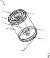
- Fig. 2 shows a perspective view of the in Fig. 1 illustrated and previously described inventive device 1.
- the in Fig. 2 illustrated device 1 is configured such that the first disc 4 for grinding and the second disc 5 for polishing the cutting edge of the cutting tool is used.
- the cutting edge of the cutting tool can be ground in a first step.
- the cutting edge of the cutting tool is placed on the surface and positioned corresponding to the first disk 4 of the device 1.
- the device body 2 is pulled along the surface by the operator. In Fig. 2 this pulling movement is indicated by the arrow "A".
- the pulling movement takes place a rotational movement of the first disc 4, which in turn ensures that the cutting edge is ground.
- the cutting edge is repositioned to the device 1. This time, however, not to the first disc 4, but to the second disc 5, which serves to polish the cutting edge of the cutting tool. Again, the device body 2 is pulled along the surface by the operator, so that by the pulling movement and the concomitant rotation of the second disc 5, the polishing of the cutting edge of the cutting tool is saturated. In this way, the cutting edge can both grind and polish.
- the invention is not limited to the example described above, but the device 1 can also be otherwise configured or used.
- the second disc 5 also serve for grinding, so that in a first step with the first disc 4 a rough grinding feasible and in a second step with the second disc 5 a finer grinding of the cutting edge is feasible.
- only one of the two discs of the device 1 according to the invention can be used either for grinding or polishing the cutting edge of the cutting tool.
Abstract
Vorrichtung zum Schleifen und/oder Polieren eines Schneidwerkzeuges, vorzugsweise eines Haushaltsmessers umfassend: - einen Vorrichtungskörper (2); - eine in dem Vorrichtungskörper (2) drehbar gelagerte Achse (3); - eine erste und eine zweite im Wesentlichen kreisrunde Scheibe (4, 5), die derartig mit der drehbaren Achse (3) verbunden sind, dass wenn der Vorrichtungskörper (2) entlang einer Oberfläche, vorzugsweise einer Tischoberfläche, gezogen wird, sich die zwei Scheiben (4, 5) relativ zu dem Vorrichtungskörper (3) drehen bzw. rotieren und wobei zumindest die erste Scheibe (4) zum Schleifen ausgebildet und derartig beschaffen ist, dass wenn eine Schneide des Schneidwerkzeuges an die erste Scheibe (4) angelegt ist und der Vorrichtungskörper (2), vorzugsweise händisch, über die Oberfläche gezogen wird, die erste Scheibe (4) aufgrund der Drehung bzw. Rotation die Schneide schleift.Device for grinding and / or polishing a cutting tool, preferably a household knife, comprising: a device body (2); - An axis in the device body (2) rotatably mounted axis (3); - A first and a second substantially circular disc (4, 5) which are connected to the rotatable shaft (3) such that when the device body (2) along a surface, preferably a table surface, is pulled, the two discs (4, 5) relative to the device body (3) rotate and wherein at least the first disc (4) is designed for grinding and is such that when a cutting edge of the cutting tool is applied to the first disc (4) and the Device body (2), preferably by hand, is pulled over the surface, the first disc (4) due to the rotation or rotation, the blade grinds.
Description
Die Erfindung bezieht sich auf eine Vorrichtung zum Schleifen und/oder Polieren sowie dem Entgraten und/oder Abziehen eines Schneidwerkzeuges, vorzugsweise eines Haushaltsmessers.The invention relates to a device for grinding and / or polishing and the deburring and / or removal of a cutting tool, preferably a household knife.
Aus dem Stand der Technik sind Vorrichtungen zum Schleifen und/oder Polieren sowie dem Entgraten und/oder Abziehen hinlänglich bekannt. So sind bspw. Vorrichtungen bekannt, bei denen das Schleifmittel auf Blöcke oder runde ggfl. auch eckige Kanten aufgebracht sind. Zum Schleifen eines Schneidwerkzeuges muss der Bediener dieses in einer Hand halten und in der anderen Hand das zu schleifende bzw. polierende Schneidwerkzeug. Die Vorrichtung muss dann von dem Bediener über die Schneide des zu schleifenden bzw. polierenden Schneidwerkezeuges gezogen werden.Devices for grinding and / or polishing as well as deburring and / or peeling are well known from the prior art. For example, devices are known in which the abrasive on blocks or round ggfl. also angular edges are applied. To grind a cutting tool, the operator must hold it in one hand and in the other hand the cutting tool to be ground or polished. The device then has to be pulled by the operator over the cutting edge of the cutting tool to be ground or polished.
Dieses Vorgehen weist den Nachteil auf, dass möglichst immer der gleiche Winkel zwischen der Schneide und dem Schneidwerkzeug gehalten werden sollte, um ein gutes Schleifergebnis zu erzielen. Dies ist insbesondere deshalb so schwierig, da sowohl das Schneidwerkzeug als auch das Schleifwerkzeug von dem Bediener quasi frei in der Luft gehalten werden müssen und somit eine hohe Geschicklichkeit des Bedieners gefragt ist.This procedure has the disadvantage that as far as possible the same angle should be kept between the cutting edge and the cutting tool in order to achieve a good grinding result. This is especially so difficult because both the cutting tool and the grinding tool must be kept virtually free in the air by the operator and thus a high level of skill of the operator is required.
Der Erfindung liegt daher die Aufgabe zugrunde, eine Vorrichtung vorzuschlagen, die einfach zu bedienen ist und darüber hinaus eine erhöhte Schleifwirkung aufweist.The invention is therefore based on the object to propose a device that is easy to use and also has an increased abrasive effect.
Die Aufgabe wird erfindungsgemäß durch die im Patentanspruch 1 genannten Merkmale gelöst. Vorteilhafte Weiterbildungen der Erfindung ergeben sich aus den Unteransprüchen.The object is achieved by the features mentioned in
Die erfindungsgemäße Vorrichtung zum Schleifen und/oder Polieren eines Schneidwerkzeuges, vorzugsweise eines Haushaltsmessers, umfasst:
- einen Vorrichtungskörper;
- eine in dem Vorrichtungskörper drehbar gelagerte Achse;
- eine erste und eine zweite im Wesentlichen kreisrunde Scheibe, die derartig mit der drehbaren Achse verbunden sind, dass wenn der Vorrichtungskörper entlang einer Oberfläche, vorzugsweise einer Tischoberfläche, gezogen wird, sich die zwei Scheiben relativ zu dem Vorrichtungskörper drehen bzw. rotieren und wobei zumindest die erste Scheibe zum Schleifen ausgebildet und derartig beschaffen ist, dass wenn eine Schneide des Schneidwerkzeuges an die erste Scheibe angelegt ist und der Vorrichtungskörper, vorzugsweise händisch, über die Oberfläche gezogen wird, die erste Scheibe aufgrund der Drehung bzw. Rotation die Schneide schleift.
- a device body;
- an axis rotatably mounted in the device body;
- a first and a second substantially circular disc connected to the rotatable shaft such that when the device body is pulled along a surface, preferably a table surface, the two discs rotate relative to the device body, and wherein at least the first disc is designed for grinding and is such that when a cutting edge of the cutting tool is applied to the first disc and the device body, preferably by hand, is pulled over the surface, the first disc due to the rotation or rotation grinds the blade.
Erfindungsgemäß wird also eine Vorrichtung vorgeschlagen, die jeweils eine Scheibe rechts und links eines im Wesentlichen zylinderförmigen Vorrichtungskörpers aufweist, wobei die beiden Scheiben über eine im Inneren des Vorrichtungskörpers gelagerte Achse lösbar verbunden sind und die Achse relativ zu dem Vorrichtungskörper rotierbar ist, so dass ein Bediener, wenn er eine Schneide des Schneidwerkzeugs an einer der beiden Scheiben anlegt und den Vorrichtungskörper über eine Oberfläche zieht, die Schneide schleifen und/oder polieren kann. Im Sinne der vorliegenden Anmeldung umfasst das Schleifen insbesondere auch ein Entgraten der Schneide und das Polieren umfasst ein Abziehen der Schneide des Schneidwerkzeuges.According to the invention, therefore, a device is proposed which has in each case a disk on the right and left of a substantially cylindrical device body, wherein the two disks are detachably connected via an axle mounted in the interior of the device body and the axis is rotatable relative to the device body, so that an operator when it applies a cutting edge of the cutting tool to one of the two discs and pulls the device body over a surface that can grind and / or polish the blade. For the purposes of the present application, the grinding in particular also includes a deburring of the cutting edge and the polishing comprises a removal of the cutting edge of the cutting tool.
Die erfindungsgemäße Vorrichtung dient zum Schleifen und/oder Polieren eines Schneidwerkzeuges mit einer Schneide, welche entweder einseitig oder beidseitig geschliffen ist. Derartige Schneidwerkzeuge stellen insbesondere handelsübliche Haushalts- bzw. Küchenmesser dar. Aber auch Messer mit grobem Wellenschliff sowie jede Art von Outdoor- und/oder Klappmesser zählen zu den Schneidwerkzeugen im Sinne der vorliegenden Anmeldung. Im Gegensatz zu den aus dem Stand der Technik bekannten Schleifvorrichtungen muss der Bediener bei der erfindungsgemäßen Vorrichtung zum Schleifen und/oder Polieren in einem ersten Schritt lediglich das Schneidwerkzeug derartig auf der Oberfläche positionieren, dass die Schneide des Schneidwerkezeuges an einer der beiden Scheiben anliegt. In einem zweiten Schritt muss der Bediener anschließend den Vorrichtungskörper entlang der Oberfläche ziehen, um so die Schneide zu Schleifen und/oder Polieren. Aufgrund dessen, dass sowohl die erfindungsgemäße Vorrichtung zum Schleifen und/oder Polieren als auch das Schneidwerkzeug auf der Oberfläche aufliegen, ist eine vereinfachte und genauere Positionierung möglich, so dass ein verbessertes Schleif- und/oder Polierergebnis erzielbar ist.The device according to the invention is used for grinding and / or polishing a cutting tool with a cutting edge, which is ground either on one side or on both sides. In particular, knives with a coarse serrated edge and any type of outdoor and / or jackknife are among the cutting tools in the sense of the present application. In contrast to the grinding devices known from the prior art, in the grinding and / or polishing apparatus according to the invention, in a first step, the user merely has to position the cutting tool on the surface in such a way that the cutting edge of the cutting tool lies against one of the two disks. In a second step, the operator then has to pull the device body along the surface so as to grind and / or polish the cutting edge. Due to the fact that both the grinding and / or polishing device according to the invention and the cutting tool rest on the surface, a simplified and more accurate positioning is possible, so that an improved grinding and / or polishing result can be achieved.
Die Erfindung ist dabei losgelöst von der Art der Oberfläche auf der die Vorrichtung entlang gezogen wird. So kann die Oberfläche bspw. eine Tischoberfläche oder auch eine Oberfläche einer Ablage, insbesondere einer Küchenablage, sein. Im Prinzip kann als Oberfläche jeglicher Gegenstand dienen, der eine zumindest abschnittsweise im Wesentlichen ebene Oberfläche aufweist, so dass das Schneidwerkzeug auf der Oberfläche positioniert und die erfindungsgemäße Vorrichtung über diesen Abschnitt des Gegenstandes gezogen werden kann.The invention is detached from the type of surface on which the device is pulled along. For example, the surface can be a table surface or even a surface of a shelf, in particular a kitchen shelf. In principle, the surface can be any object which has an at least partially substantially flat surface, so that the cutting tool can be positioned on the surface and the device according to the invention can be pulled over this section of the object.
Eine vorteilhafte Weiterbildung der Erfindung sieht vor, dass die erste und/oder die zweite Scheibe lösbar mit der Achse verbunden sind, so dass diese austauschbar ist bzw. sind. Aufgrund dessen, dass sowohl die erste als auch die zweite Scheibe lösbar mit der Achse verbunden sind, können diese einfach durch den Bediener ausgetauscht werden. Dies kann bspw. dann von Vorteil sein, wenn ein der beiden Scheiben ersetzt werden muss, bspw. aus Altersgründen oder aber, wenn der Bediener die Vorrichtung zum Schleifen und/oder Polieren auf das Schneidwerkzeug besser anpassen möchte. Insbesondere wenn unterschiedliche Schneidwerkzeuge geschliffen und/oder poliert werden sollen, kann es von Vorteil sein, das die beiden Scheiben austauschbar sind, um so die Vorrichtung für das jeweilige Schleifwerkzeug exakt anzupassen. Beispielsweise kann die Vorrichtung somit derartig konfiguriert werden, dass eine Scheibe ein Schleifmittel zum Schleifen der Schneide und die andere Scheibe ein Mittel zum Abziehen der Schneide aufweist, so dass die Schneide des Schneidwerkzeuges sowohl geschliffen als auch abgezogen werden kann. Die vorteilhafte Weiterbildung der Erfindung kann insbesondere auch vorsehen, dass die erste Scheibe einen ersten angedrehten Gewindebolzen und/oder die zweite Scheibe einen zweiten angedrehten Gewindebolzen aufweist bzw. aufweisen, so dass die erste und/oder die zweite Scheibe mit der Achse lösbar verschraubbar ist bzw. sind. Auf diese Weise ist der Austausch, bspw. wegen Verschleiß oder Wechsel des Schleifverfahrens relativ schnell und einfach möglich.An advantageous development of the invention provides that the first and / or the second disc are detachably connected to the axle, so that it is or are interchangeable. Due to the fact that both the first and the second disc are releasably connected to the axle, they can be easily replaced by the operator. This may, for example, be advantageous if one of the two discs must be replaced, for example, for reasons of age or if the operator would like to better adapt the device for grinding and / or polishing on the cutting tool. In particular, when different cutting tools are to be ground and / or polished, it may be advantageous to use the two discs are interchangeable, so as to adapt the device for each grinding tool exactly. For example, the device may thus be configured such that one disc has a grinding means for grinding the cutting edge and the other disc has means for removing the cutting edge so that the cutting edge of the cutting tool can be both ground and withdrawn. The advantageous development of the invention can also provide, in particular, for the first disk to have or to have a first threaded bolt and / or the second disk to have a second threaded bolt turned on, so that the first and / or the second disk can be detachably screwed to the axle or . are. In this way, the exchange, for example, due to wear or change of the grinding process relatively quickly and easily possible.
Eine weitere vorteilhafte Weiterbildung der Erfindung sieht vor, dass zumindest die erste Scheibe ein erstes Schleifmittel aufweist und das erste Schleifmittel Rubin, Saphir, Diamant, Glas, Keramik, Korund oder Karbid oder eine Kombination der genannten Materialien aufweist.A further advantageous development of the invention provides that at least the first disc has a first abrasive and the first abrasive ruby, sapphire, diamond, glass, ceramic, corundum or carbide or a combination of said materials.
Wiederum eine weitere vorteilhafte Weiterbildung der Erfindung sieht vor, dass die zweite Scheibe zum Polieren ausgebildet ist, so dass wenn die Schneide des Schneidwerkzeuges an die zweite Scheibe angelegt ist und der Vorrichtungskörper, vorzugsweise händisch, über die Oberfläche gezogen wird, die zweite Scheibe aufgrund der Drehung bzw. Rotation die Schneide poliert. Die vorteilhafte Weiterbildung kann insbesondere vorsehen, dass die zweite Scheibe derartig ausgebildet ist, dass zumindest eine im Wesentlichen zum Mittelpunkt der zweiten Scheibe konzentrische Vertiefung vorgesehen ist.Yet another advantageous development of the invention provides that the second disc is designed for polishing, so that when the cutting edge of the cutting tool is applied to the second disc and the device body, preferably by hand, is pulled over the surface, the second disc due to Rotation or rotation polished the cutting edge. The advantageous further development can provide, in particular, that the second disk is designed in such a way that at least one recess concentric with the center of the second disk is provided.
Eine alternative Weiterbildung der Erfindung sieht vor, dass die zweite Scheibe ebenfalls zum Schleifen ausgebildet ist und ein zweites Schleifmittel aufweist und das zweite Schleifmittel Rubin, Saphir, Diamant, Glas, Keramik, Korund oder Karbid oder eine Kombination der genannten Materialien aufweist. Insbesondere sieht die Weiterbildung vor, dass das erste und zweite Schleifmittel unterschiedlich sind, so dass die erste und die zweite Scheibe eine unterschiedliche Schleifwirkung erzielen. Aufgrund der unterschiedlichen Schleifwirkung der beiden Scheiben ist es bspw. möglich, dass mit der ersten Scheibe eine grobe Schleifung der Schneide des Schneidwerkzeuges erfolgt und mit der zweiten Scheibe eine feine Schleifung der Schneide erfolgt, um so ein möglichst perfektes Schleifergebnis zu erzielen.An alternative development of the invention provides that the second disc is also designed for grinding and has a second abrasive and the second abrasive ruby, sapphire, diamond, glass, ceramic, corundum or carbide or a combination of said materials. In particular, the training provides that the first and second Abrasives are different, so that the first and the second disc achieve a different grinding effect. Due to the different grinding action of the two disks, it is for example possible that a rough grinding of the cutting edge of the cutting tool takes place with the first disk and a fine sharpening of the cutting edge takes place with the second disk so as to achieve the most perfect possible grinding result.
Die Erfindung wird anhand der nachfolgenden Zeichnungen näher erläutert. Es zeigt:
-
Fig. 1 : eine Seitenansicht der erfindungsgemäßen Vorrichtung zum Schleifen und/oder Polieren, und -
Fig. 2 : eine perspektivische Ansicht der inFig. 1 dargestellten erfindungsgemäßen Vorrichtung.
-
Fig. 1 a side view of the device according to the invention for grinding and / or polishing, and -
Fig. 2 : a perspective view of the inFig. 1 illustrated device according to the invention.
In dem Vorrichtungskörper 2 ist eine relativ zu dem Vorrichtungskörper 2 drehbar gelagerte Achse 3 ausgebildet. Die Achse 3 verläuft von der Stirnseite zu einer der Stirnseite abgewandten Seite im Inneren des Vorrichtungskörpers 2 und ist in ihren beiden Enden so ausgebildet, dass jeweils eine Scheibe 4, 5 lösbar anbringbar ist.In the
Die erfindungsgemäße Vorrichtung zum Schleifen und/oder Polieren 1 umfasst ferner eine erste und eine zweite kreisrunde Scheibe 4, 5, wobei eine Scheibe 4 an der ersten Stirnseite und die andere Scheibe 5 an der der Stirnseite abgewandten Seite des Vorrichtungskörpers 2 mit der Achse 3 lösbar verbunden sind.The inventive apparatus for grinding and / or
Das lösbare Anbringen der beiden Scheiben 4, 5 an die Achse 3 erlaubt es, die Vorrichtung zum Schleifen und/oder Polieren 1 beliebig anzupassen. Beispielsweise kann die Vorrichtung 1 so an unterschiedliche Schneiderwerkzeuge angepasst werden. Aber auch das Austauschen einer alten oder auch defekten Scheibe ist somit problemlos möglich. Um einen besonders schnellen und einfachen Austausch der Scheiben zu ermöglichen, ist vorzugsweise an jeder Scheibe ein angedrehter Gewindebolzen 11, 12 ausgebildet, über den sich die jeweilige Scheibe 4, 5 an der Achse 3 lösbar anbringen lässt. Die Erfindung ist dabei nicht darauf beschränkt, dass beide Scheiben 4, 5 lösbar mit der Achse 3, bspw. über den jeweiligen Gewindebolzen 11, 12, verbindbar sind. So ist es ebenfalls denkbar, dass eine der beiden Scheiben fest und lediglich die andere der beiden Scheiben lösbar mit der Achse verbunden ist.The detachable attachment of the two
Die erste Scheibe 4 weist ein erstes Schleifmittel zum Schleifen der Schneide des Schneidwerkzeuges auf. Das erste Schleifmittel umfasst vorzugsweise Rubin, Saphir, Diamant, Glas, Keramik, Korund oder Karbid. Ferner kann das erste Schleifmittel auch eine Kombination der zuvor genannten Materialen aufweisen. Mit Hilfe der ersten Scheibe 4 und des ersten Schleifmittels kann die Schneide des Schneidwerkzeuges geschliffen werden, in dem das Schneidwerkzeug auf der Oberfläche positioniert wird, und der Vorrichtungskörper 2 anschließend zum Schleifen über die Oberfläche gezogen wird.The
Die zweite Scheibe 5 kann einerseits so ausgebildet sein, dass sie entwerder zum Polieren oder zum Schleifen der Schneide des Schneidwerkzeuges dient.On the one hand, the
In
In dem Fall, dass die zweite Scheibe 5 zum Polieren dienen soll, weist diese zumindest eine, vorzugsweise mehrere, im Wesentlichen zum Mittelpunkt der zweiten Scheibe konzentrische Vertiefung bzw. Vertiefungen 8 auf. Durch die Vertiefung bzw. Vertiefungen 8 wird durch die beim Ziehen des Vorrichtungskörpers 2 über die Oberfläche hervorgerufene Rotation der zweiten Scheibe 5 eine verbesserte Polierwirkung erzielt.In the event that the
Die zweite Scheibe 5 kann aber auch ein zweites Schleifmittel 10 aufweisen, welches vorzugsweise Rubin, Saphir, Diamant, Glas, Keramik, Korund oder Karbid umfasst. Ferner kann das zweite Schleifmittel 10 auch eine Kombination der zuvor genannten Materialen aufweisen. Das zweite Schleifmittel ist vorzugsweise derartig ausgebildet, dass die zweite Scheibe 5 mit dem zweiten Schleifmittel eine unterschiedliche Schleifwirkung zu der ersten Scheibe 4 mit dem ersten Schleifmittel aufweist. Die unterschiedliche Schleifwirkung kann dabei auf unterschiedliche Art und Weise realisiert werden. Bspw. kann die unterschiedliche Schleifwirkung dadurch erzielt werden, dass das erste und das zweite Schleifmittel unterschiedliche Schleifmaterialen, der zuvor genannten Materialien, umfassen. Ferner kann sie auch durch eine auf die Scheiben unterschiedlich aufgebrachte Körnung erzielt werden. Aber auch eine auf den einzelnen Scheiben unterschiedlich ausgebildete Dichte der aus den zuvor genannten Materialen bestehenden Materialkörner, insbesondere der Diamantkörner, pro Flächeninhalt kann zu der unterschiedlichen Schleifwirkung führen. Für gewöhnlich wird das entsprechende Schleifmittel galvanisch auf die Scheiben aufgenickelt, so dass auch über die sehr variabel steuerbare Dicke der Nickelschicht um die Körner herum die Schleifwirkung angepasst werden kann.The
Um eine einfache und leise Laufbewegung der beiden Scheiben beim Ziehen des Vorrichtungskörpers 2 über die Oberfläche zu erhalten, umfassen die beiden Scheiben jeweils einen umlaufenden Gummiring 6, 7. Die Gummiringe sind jeweils durch eine die jeweilige Scheibe umlaufenden Nut fixiert, so dass sie einerseits nicht verrutschen können, aber dennoch austauschbar sind.To obtain a simple and quiet running movement of the two disks when pulling the
Mit Hilfe der derartig konfigurierten erfindungsgemäßen Vorrichtung 1 lässt sich die Schneide des Schneidwerkzeuges in einem ersten Schritt schleifen. Hierzu wird die Schneide des Schneidwerkzeuges auf der Oberfläche aufgesetzt und zu der ersten Scheibe 4 der Vorrichtung 1 entsprechend positioniert. Anschließend wird der Vorrichtungskörper 2 durch den Bediener entlang der Oberfläche gezogen. In
In einem zweiten Schritt, wird nach dem Schleifen die Schneide erneut zur Vorrichtung 1 positioniert. Diesmal jedoch nicht zur ersten Scheibe 4, sondern zur zweiten Scheibe 5, die zum Polieren der Schneide des Schneidwerkzeuges dient. Wiederum wird der Vorrichtungskörper 2 entlang der Oberfläche durch den Bediener gezogen, so dass durch die Zugbewegung und der damit einhergehenden Rotation der zweiten Scheibe 5 das Polieren der Schneide des Schneidwerkzeuges sattfindet. Auf diese Weise lässt sich die Schneide sowohl schleifen als auch polieren.In a second step, after grinding, the cutting edge is repositioned to the
Es versteht sich von selbst, dass die Erfindung nicht auf das zuvor beschriebene Beispiel beschränkt ist, sondern die Vorrichtung 1 auch anderweitig konfiguriert bzw. eingesetzt werden kann. Beispielsweise kann, wie bereits angedeutet, die zweite Scheibe 5 ebenfalls zum Schleifen dienen, so dass in einem ersten Schritt mit der ersten Scheibe 4 eine grobe Schleifung durchführbar und in einem zweiten Schritt mit der zweiten Scheibe 5 eine feinere Schleifung der Schneide durchführbar ist. Selbstverständlich kann auch nur eine der beiden Scheiben der erfindungsgemäßen Vorrichtung 1 entweder zum Schleifen oder zum Polieren der Schneide des Schneidwerkzeuges eingesetzt werden.It goes without saying that the invention is not limited to the example described above, but the
- 11
- Vorrichtung zum Schleifen und/oder PolierenDevice for grinding and / or polishing
- 22
- Vorrichtungskörperdevice body
- 33
- Achseaxis
- 44
- Erste ScheibeFirst disc
- 55
- Zweite ScheibeSecond disc
- 66
- Erster GummiringFirst rubber ring
- 77
- Zweiter GummiringSecond rubber ring
- 88th
- Konzentrische VertiefungConcentric recess
- 99
- Erstes SchleifmittelFirst abrasive
- 1010
- Zweites SchleifmittelSecond abrasive
- 1111
- Erster GewindebolzenFirst threaded bolt
- 1212
- Zweiter GewindebolzenSecond threaded bolt
- AA
- Zugbewegungpulling
Claims (8)
Applications Claiming Priority (1)
| Application Number | Priority Date | Filing Date | Title |
|---|---|---|---|
| DE102016009482.6A DE102016009482B4 (en) | 2016-08-05 | 2016-08-05 | Device for grinding and / or polishing a cutting tool |
Publications (3)
| Publication Number | Publication Date |
|---|---|
| EP3278928A2 true EP3278928A2 (en) | 2018-02-07 |
| EP3278928A3 EP3278928A3 (en) | 2018-05-30 |
| EP3278928B1 EP3278928B1 (en) | 2021-02-17 |
Family
ID=59506048
Family Applications (1)
| Application Number | Title | Priority Date | Filing Date |
|---|---|---|---|
| EP17001311.4A Active EP3278928B1 (en) | 2016-08-05 | 2017-07-31 | Device for grinding and/or polishing a cutting tool |
Country Status (5)
| Country | Link |
|---|---|
| EP (1) | EP3278928B1 (en) |
| DE (3) | DE102016009482B4 (en) |
| DK (1) | DK3278928T3 (en) |
| ES (1) | ES2870051T3 (en) |
| PT (1) | PT3278928T (en) |
Cited By (9)
| Publication number | Priority date | Publication date | Assignee | Title |
|---|---|---|---|---|
| EP3278928B1 (en) | 2016-08-05 | 2021-02-17 | HORL 1993 GmbH | Device for grinding and/or polishing a cutting tool |
| DE102020203144A1 (en) | 2020-03-11 | 2021-09-16 | Horl 1993 Gmbh | Roll grinder pro |
| DE102020123501B3 (en) | 2020-09-09 | 2022-03-10 | Horl 1993 Gmbh | Roller grinder with press fit between roller and axle |
| DE102020123500A1 (en) | 2020-09-09 | 2022-03-10 | Horl 1993 Gmbh | Magnetic grinding gauge with elastic contact element |
| DE102020123499A1 (en) | 2020-09-09 | 2022-03-10 | Horl 1993 Gmbh | Process for manufacturing a roller grinder with minimal gap dimensions between the roller and the handle body |
| DE102020123503A1 (en) | 2020-09-09 | 2022-03-10 | Horl 1993 Gmbh | Grinding gauge with adjustable angle |
| DE102020133853B3 (en) | 2020-12-16 | 2022-04-28 | Horl 1993 Gmbh | Cutting tool with support section for preset sharpening angle |
| DE202022001390U1 (en) | 2022-06-17 | 2022-07-07 | Magna-Tec e.K. | Device for grinding and/or polishing a cutting tool |
| DE202022002459U1 (en) | 2022-11-16 | 2023-01-24 | Magna-Tec e.K. | Reference plane for optimization when grinding using a roller grinding device |
Families Citing this family (2)
| Publication number | Priority date | Publication date | Assignee | Title |
|---|---|---|---|---|
| DE202020001180U1 (en) | 2020-03-25 | 2020-04-23 | Mobiset Gmbh | Roll grinder and roll grinder set |
| EP4334082A1 (en) | 2021-05-05 | 2024-03-13 | HORL 1993 GmbH | Scissors which can be transferred between a cutting configuration and a sharpening configuration |
Citations (6)
| Publication number | Priority date | Publication date | Assignee | Title |
|---|---|---|---|---|
| US948362A (en) | 1908-04-23 | 1910-02-08 | John Allan Wilkinson | Sharpener for cutlery. |
| US1388882A (en) | 1920-09-29 | 1921-08-30 | Paul Adolf | Blade-sharpener |
| GB437733A (en) | 1933-04-28 | 1935-10-28 | Thomas Holtan | Improvements in sharpening apparatus |
| US2475110A (en) | 1947-04-23 | 1949-07-05 | Leo E Pryor | Knife sharpener |
| DE29703326U1 (en) | 1997-02-25 | 1997-06-12 | Horl Otmar | Grinding and honing tool, for grinding cutting edges, which is designed as a self-propelled roller or disc with a handle |
| US20130295824A1 (en) | 2012-05-03 | 2013-11-07 | Kabushiki Kaisha Suehiro | Blade Sharpener |
Family Cites Families (4)
| Publication number | Priority date | Publication date | Assignee | Title |
|---|---|---|---|---|
| US2469797A (en) * | 1947-05-02 | 1949-05-10 | Alden Speare S Sons Co | Knife sharpener |
| DE1910417U (en) * | 1964-11-06 | 1965-02-18 | Theodor Jacob | APPARATUS FOR SHARPENING KNIVES. |
| DE102016009482B4 (en) | 2016-08-05 | 2018-06-14 | Timo Horl | Device for grinding and / or polishing a cutting tool |
| DE202020001180U1 (en) | 2020-03-25 | 2020-04-23 | Mobiset Gmbh | Roll grinder and roll grinder set |
-
2016
- 2016-08-05 DE DE102016009482.6A patent/DE102016009482B4/en active Active
-
2017
- 2017-07-31 PT PT170013114T patent/PT3278928T/en unknown
- 2017-07-31 ES ES17001311T patent/ES2870051T3/en active Active
- 2017-07-31 DE DE202017007377.3U patent/DE202017007377U1/en active Active
- 2017-07-31 EP EP17001311.4A patent/EP3278928B1/en active Active
- 2017-07-31 DE DE202017007115.0U patent/DE202017007115U1/en active Active
- 2017-07-31 DK DK17001311.4T patent/DK3278928T3/en active
Patent Citations (6)
| Publication number | Priority date | Publication date | Assignee | Title |
|---|---|---|---|---|
| US948362A (en) | 1908-04-23 | 1910-02-08 | John Allan Wilkinson | Sharpener for cutlery. |
| US1388882A (en) | 1920-09-29 | 1921-08-30 | Paul Adolf | Blade-sharpener |
| GB437733A (en) | 1933-04-28 | 1935-10-28 | Thomas Holtan | Improvements in sharpening apparatus |
| US2475110A (en) | 1947-04-23 | 1949-07-05 | Leo E Pryor | Knife sharpener |
| DE29703326U1 (en) | 1997-02-25 | 1997-06-12 | Horl Otmar | Grinding and honing tool, for grinding cutting edges, which is designed as a self-propelled roller or disc with a handle |
| US20130295824A1 (en) | 2012-05-03 | 2013-11-07 | Kabushiki Kaisha Suehiro | Blade Sharpener |
Cited By (20)
| Publication number | Priority date | Publication date | Assignee | Title |
|---|---|---|---|---|
| EP3278928B1 (en) | 2016-08-05 | 2021-02-17 | HORL 1993 GmbH | Device for grinding and/or polishing a cutting tool |
| DE102020203144A1 (en) | 2020-03-11 | 2021-09-16 | Horl 1993 Gmbh | Roll grinder pro |
| WO2021180687A1 (en) | 2020-03-11 | 2021-09-16 | Horl 1993 Gmbh | Roller sander |
| AU2021233125B2 (en) * | 2020-03-11 | 2023-11-23 | Horl 1993 Gmbh | Roller grinder |
| CN115297996A (en) * | 2020-03-11 | 2022-11-04 | 霍尔1993有限责任公司 | Roller mill |
| DE102020203144B4 (en) | 2020-03-11 | 2022-06-15 | Horl 1993 Gmbh | roller sander per |
| WO2022053517A1 (en) * | 2020-09-09 | 2022-03-17 | Horl 1993 Gmbh | Rolling grinder with press fit between roller and shaft |
| DE102020123499A1 (en) | 2020-09-09 | 2022-03-10 | Horl 1993 Gmbh | Process for manufacturing a roller grinder with minimal gap dimensions between the roller and the handle body |
| WO2022053477A1 (en) | 2020-09-09 | 2022-03-17 | Horl 1993 Gmbh | Magnetic sharpening jig comprising a flexible contact element |
| WO2022053518A1 (en) | 2020-09-09 | 2022-03-17 | Horl 1993 Gmbh | Sharpening jig having an adjustable angle |
| DE102020123503A1 (en) | 2020-09-09 | 2022-03-10 | Horl 1993 Gmbh | Grinding gauge with adjustable angle |
| DE102020123499B4 (en) | 2020-09-09 | 2022-04-28 | Horl 1993 Gmbh | Process for manufacturing a roller grinder with minimal gap dimensions between the roller and the handle body |
| DE202021004402U1 (en) | 2020-09-09 | 2024-03-04 | Horl 1993 Gmbh | Magnetic grinding gauge with elastic contact element |
| WO2022053479A1 (en) * | 2020-09-09 | 2022-03-17 | Horl 1993 Gmbh | Method for producing a roll grinder with minimal gap dimensions between the running roller and the handle body |
| DE102020123501B3 (en) | 2020-09-09 | 2022-03-10 | Horl 1993 Gmbh | Roller grinder with press fit between roller and axle |
| DE102020123500A1 (en) | 2020-09-09 | 2022-03-10 | Horl 1993 Gmbh | Magnetic grinding gauge with elastic contact element |
| WO2022128728A1 (en) | 2020-12-16 | 2022-06-23 | Horl 1993 Gmbh | Cutting tool with supporting portion for pre-set grinding angle |
| DE102020133853B3 (en) | 2020-12-16 | 2022-04-28 | Horl 1993 Gmbh | Cutting tool with support section for preset sharpening angle |
| DE202022001390U1 (en) | 2022-06-17 | 2022-07-07 | Magna-Tec e.K. | Device for grinding and/or polishing a cutting tool |
| DE202022002459U1 (en) | 2022-11-16 | 2023-01-24 | Magna-Tec e.K. | Reference plane for optimization when grinding using a roller grinding device |
Also Published As
| Publication number | Publication date |
|---|---|
| DE102016009482B4 (en) | 2018-06-14 |
| ES2870051T3 (en) | 2021-10-26 |
| DK3278928T3 (en) | 2021-05-10 |
| DE202017007377U1 (en) | 2021-01-28 |
| PT3278928T (en) | 2021-04-28 |
| EP3278928A3 (en) | 2018-05-30 |
| DE102016009482A1 (en) | 2018-02-08 |
| EP3278928B1 (en) | 2021-02-17 |
| DE202017007115U1 (en) | 2019-08-07 |
Similar Documents
| Publication | Publication Date | Title |
|---|---|---|
| DE102016009482B4 (en) | Device for grinding and / or polishing a cutting tool | |
| DE60101652T2 (en) | GRINDING TOOL | |
| EP2071991B1 (en) | Cutting board | |
| DE202020001180U1 (en) | Roll grinder and roll grinder set | |
| DE112004001505B4 (en) | Manual sharpening device | |
| DE202012101515U1 (en) | Abrasive and grinding tool | |
| EP2961567A2 (en) | Cutting disc and carrier body for a cutting wheel for forming a bevel | |
| DE102023001542A1 (en) | Device for grinding and/or polishing a cutting tool | |
| DE102007045351B3 (en) | segment blade | |
| DE102019102200A1 (en) | Knife sharpening device with breakpoints | |
| AT523721B1 (en) | Device for sharpening blades | |
| DE1093692B (en) | Cutting tool, in particular for dressing grinding wheels | |
| DE495497C (en) | Device for cutting out floors, rings, discs etc. from sheet metal using a circular knife | |
| DE3413455A1 (en) | Portable grinding machine for workpieces of stone | |
| DE40560C (en) | Grinding and polishing machine for toothpicks | |
| DE1804933A1 (en) | Diamond cup grinding wheel | |
| DE481774C (en) | Sharpening device for embroidery machine drill | |
| DE602004002349T2 (en) | Knife blade grinding device with unit for the restoration of the cutting edge | |
| DE102009050594B4 (en) | Grinding, sharpening and removal device for knives | |
| DE102009009670B4 (en) | Knife guiding device for a knife sharpening device | |
| DE202009005549U1 (en) | Universal edge sharpener with puller | |
| DE377498C (en) | Device for grinding double-edged wing knives for meat wolves | |
| WO2012037584A1 (en) | Method and arrangement for resharpening grinding wheels | |
| DE422450C (en) | Device for sharpening straight razors and razor blades | |
| DE7334233U (en) | Device for grinding objects of various types |
Legal Events
| Date | Code | Title | Description |
|---|---|---|---|
| REG | Reference to a national code |
Ref country code: DE Ref legal event code: R138 Ref document number: 202017007377 Country of ref document: DE Free format text: GERMAN DOCUMENT NUMBER IS 502017009303 Ref country code: DE Ref legal event code: R138 Ref document number: 202017007115 Country of ref document: DE Free format text: GERMAN DOCUMENT NUMBER IS 502017009303 |
|
| PUAI | Public reference made under article 153(3) epc to a published international application that has entered the european phase |
Free format text: ORIGINAL CODE: 0009012 |
|
| STAA | Information on the status of an ep patent application or granted ep patent |
Free format text: STATUS: THE APPLICATION HAS BEEN PUBLISHED |
|
| AK | Designated contracting states |
Kind code of ref document: A2 Designated state(s): AL AT BE BG CH CY CZ DE DK EE ES FI FR GB GR HR HU IE IS IT LI LT LU LV MC MK MT NL NO PL PT RO RS SE SI SK SM TR |
|
| AX | Request for extension of the european patent |
Extension state: BA ME |
|
| PUAL | Search report despatched |
Free format text: ORIGINAL CODE: 0009013 |
|
| AK | Designated contracting states |
Kind code of ref document: A3 Designated state(s): AL AT BE BG CH CY CZ DE DK EE ES FI FR GB GR HR HU IE IS IT LI LT LU LV MC MK MT NL NO PL PT RO RS SE SI SK SM TR |
|
| AX | Request for extension of the european patent |
Extension state: BA ME |
|
| RIC1 | Information provided on ipc code assigned before grant |
Ipc: B24B 3/54 20060101ALI20180420BHEP Ipc: B24D 15/08 20060101AFI20180420BHEP |
|
| STAA | Information on the status of an ep patent application or granted ep patent |
Free format text: STATUS: REQUEST FOR EXAMINATION WAS MADE |
|
| 17P | Request for examination filed |
Effective date: 20181121 |
|
| RBV | Designated contracting states (corrected) |
Designated state(s): AL AT BE BG CH CY CZ DE DK EE ES FI FR GB GR HR HU IE IS IT LI LT LU LV MC MK MT NL NO PL PT RO RS SE SI SK SM TR |
|
| TPAC | Observations filed by third parties |
Free format text: ORIGINAL CODE: EPIDOSNTIPA |
|
| STAA | Information on the status of an ep patent application or granted ep patent |
Free format text: STATUS: EXAMINATION IS IN PROGRESS |
|
| 17Q | First examination report despatched |
Effective date: 20200303 |
|
| GRAP | Despatch of communication of intention to grant a patent |
Free format text: ORIGINAL CODE: EPIDOSNIGR1 |
|
| STAA | Information on the status of an ep patent application or granted ep patent |
Free format text: STATUS: GRANT OF PATENT IS INTENDED |
|
| GRAS | Grant fee paid |
Free format text: ORIGINAL CODE: EPIDOSNIGR3 |
|
| INTG | Intention to grant announced |
Effective date: 20201208 |
|
| GRAA | (expected) grant |
Free format text: ORIGINAL CODE: 0009210 |
|
| STAA | Information on the status of an ep patent application or granted ep patent |
Free format text: STATUS: THE PATENT HAS BEEN GRANTED |
|
| AK | Designated contracting states |
Kind code of ref document: B1 Designated state(s): AL AT BE BG CH CY CZ DE DK EE ES FI FR GB GR HR HU IE IS IT LI LT LU LV MC MK MT NL NO PL PT RO RS SE SI SK SM TR |
|
| RAP1 | Party data changed (applicant data changed or rights of an application transferred) |
Owner name: HORL 1993 GMBH |
|
| REG | Reference to a national code |
Ref country code: GB Ref legal event code: FG4D Free format text: NOT ENGLISH |
|
| RIN1 | Information on inventor provided before grant (corrected) |
Inventor name: HORL, TIMO |
|
| REG | Reference to a national code |
Ref country code: CH Ref legal event code: EP |
|
| REG | Reference to a national code |
Ref country code: DE Ref legal event code: R096 Ref document number: 502017009303 Country of ref document: DE |
|
| REG | Reference to a national code |
Ref country code: AT Ref legal event code: REF Ref document number: 1360862 Country of ref document: AT Kind code of ref document: T Effective date: 20210315 |
|
| REG | Reference to a national code |
Ref country code: IE Ref legal event code: FG4D Free format text: LANGUAGE OF EP DOCUMENT: GERMAN |
|
| REG | Reference to a national code |
Ref country code: CH Ref legal event code: NV Representative=s name: BOVARD AG PATENT- UND MARKENANWAELTE, CH |
|
| REG | Reference to a national code |
Ref country code: NL Ref legal event code: FP |
|
| REG | Reference to a national code |
Ref country code: PT Ref legal event code: SC4A Ref document number: 3278928 Country of ref document: PT Date of ref document: 20210428 Kind code of ref document: T Free format text: AVAILABILITY OF NATIONAL TRANSLATION Effective date: 20210422 |
|
| REG | Reference to a national code |
Ref country code: SE Ref legal event code: TRGR |
|
| REG | Reference to a national code |
Ref country code: FI Ref legal event code: FGE |
|
| REG | Reference to a national code |
Ref country code: DK Ref legal event code: T3 Effective date: 20210506 |
|
| REG | Reference to a national code |
Ref country code: DE Ref legal event code: R026 Ref document number: 502017009303 Country of ref document: DE |
|
| PLBI | Opposition filed |
Free format text: ORIGINAL CODE: 0009260 |
|
| REG | Reference to a national code |
Ref country code: NO Ref legal event code: T2 Effective date: 20210217 |
|
| REG | Reference to a national code |
Ref country code: FI Ref legal event code: MDE Opponent name: MOBISET GMBH |
|
| 26 | Opposition filed |
Opponent name: MOBISET GMBH Effective date: 20210531 |
|
| REG | Reference to a national code |
Ref country code: LT Ref legal event code: MG9D |
|
| PG25 | Lapsed in a contracting state [announced via postgrant information from national office to epo] |
Ref country code: LT Free format text: LAPSE BECAUSE OF FAILURE TO SUBMIT A TRANSLATION OF THE DESCRIPTION OR TO PAY THE FEE WITHIN THE PRESCRIBED TIME-LIMIT Effective date: 20210217 Ref country code: BG Free format text: LAPSE BECAUSE OF FAILURE TO SUBMIT A TRANSLATION OF THE DESCRIPTION OR TO PAY THE FEE WITHIN THE PRESCRIBED TIME-LIMIT Effective date: 20210517 Ref country code: GR Free format text: LAPSE BECAUSE OF FAILURE TO SUBMIT A TRANSLATION OF THE DESCRIPTION OR TO PAY THE FEE WITHIN THE PRESCRIBED TIME-LIMIT Effective date: 20210518 Ref country code: HR Free format text: LAPSE BECAUSE OF FAILURE TO SUBMIT A TRANSLATION OF THE DESCRIPTION OR TO PAY THE FEE WITHIN THE PRESCRIBED TIME-LIMIT Effective date: 20210217 |
|
| PG25 | Lapsed in a contracting state [announced via postgrant information from national office to epo] |
Ref country code: LV Free format text: LAPSE BECAUSE OF FAILURE TO SUBMIT A TRANSLATION OF THE DESCRIPTION OR TO PAY THE FEE WITHIN THE PRESCRIBED TIME-LIMIT Effective date: 20210217 Ref country code: PL Free format text: LAPSE BECAUSE OF FAILURE TO SUBMIT A TRANSLATION OF THE DESCRIPTION OR TO PAY THE FEE WITHIN THE PRESCRIBED TIME-LIMIT Effective date: 20210217 Ref country code: RS Free format text: LAPSE BECAUSE OF FAILURE TO SUBMIT A TRANSLATION OF THE DESCRIPTION OR TO PAY THE FEE WITHIN THE PRESCRIBED TIME-LIMIT Effective date: 20210217 |
|
| PG25 | Lapsed in a contracting state [announced via postgrant information from national office to epo] |
Ref country code: IS Free format text: LAPSE BECAUSE OF FAILURE TO SUBMIT A TRANSLATION OF THE DESCRIPTION OR TO PAY THE FEE WITHIN THE PRESCRIBED TIME-LIMIT Effective date: 20210617 |
|
| REG | Reference to a national code |
Ref country code: ES Ref legal event code: FG2A Ref document number: 2870051 Country of ref document: ES Kind code of ref document: T3 Effective date: 20211026 |
|
| PG25 | Lapsed in a contracting state [announced via postgrant information from national office to epo] |
Ref country code: SM Free format text: LAPSE BECAUSE OF FAILURE TO SUBMIT A TRANSLATION OF THE DESCRIPTION OR TO PAY THE FEE WITHIN THE PRESCRIBED TIME-LIMIT Effective date: 20210217 Ref country code: EE Free format text: LAPSE BECAUSE OF FAILURE TO SUBMIT A TRANSLATION OF THE DESCRIPTION OR TO PAY THE FEE WITHIN THE PRESCRIBED TIME-LIMIT Effective date: 20210217 Ref country code: CZ Free format text: LAPSE BECAUSE OF FAILURE TO SUBMIT A TRANSLATION OF THE DESCRIPTION OR TO PAY THE FEE WITHIN THE PRESCRIBED TIME-LIMIT Effective date: 20210217 |
|
| PLAX | Notice of opposition and request to file observation + time limit sent |
Free format text: ORIGINAL CODE: EPIDOSNOBS2 |
|
| PG25 | Lapsed in a contracting state [announced via postgrant information from national office to epo] |
Ref country code: SK Free format text: LAPSE BECAUSE OF FAILURE TO SUBMIT A TRANSLATION OF THE DESCRIPTION OR TO PAY THE FEE WITHIN THE PRESCRIBED TIME-LIMIT Effective date: 20210217 Ref country code: RO Free format text: LAPSE BECAUSE OF FAILURE TO SUBMIT A TRANSLATION OF THE DESCRIPTION OR TO PAY THE FEE WITHIN THE PRESCRIBED TIME-LIMIT Effective date: 20210217 |
|
| PG25 | Lapsed in a contracting state [announced via postgrant information from national office to epo] |
Ref country code: AL Free format text: LAPSE BECAUSE OF FAILURE TO SUBMIT A TRANSLATION OF THE DESCRIPTION OR TO PAY THE FEE WITHIN THE PRESCRIBED TIME-LIMIT Effective date: 20210217 |
|
| PG25 | Lapsed in a contracting state [announced via postgrant information from national office to epo] |
Ref country code: SI Free format text: LAPSE BECAUSE OF FAILURE TO SUBMIT A TRANSLATION OF THE DESCRIPTION OR TO PAY THE FEE WITHIN THE PRESCRIBED TIME-LIMIT Effective date: 20210217 |
|
| PG25 | Lapsed in a contracting state [announced via postgrant information from national office to epo] |
Ref country code: MC Free format text: LAPSE BECAUSE OF FAILURE TO SUBMIT A TRANSLATION OF THE DESCRIPTION OR TO PAY THE FEE WITHIN THE PRESCRIBED TIME-LIMIT Effective date: 20210217 |
|
| PLBB | Reply of patent proprietor to notice(s) of opposition received |
Free format text: ORIGINAL CODE: EPIDOSNOBS3 |
|
| PG25 | Lapsed in a contracting state [announced via postgrant information from national office to epo] |
Ref country code: IS Free format text: LAPSE BECAUSE OF FAILURE TO SUBMIT A TRANSLATION OF THE DESCRIPTION OR TO PAY THE FEE WITHIN THE PRESCRIBED TIME-LIMIT Effective date: 20210617 |
|
| PG25 | Lapsed in a contracting state [announced via postgrant information from national office to epo] |
Ref country code: IE Free format text: LAPSE BECAUSE OF NON-PAYMENT OF DUE FEES Effective date: 20210731 |
|
| PG25 | Lapsed in a contracting state [announced via postgrant information from national office to epo] |
Ref country code: HU Free format text: LAPSE BECAUSE OF FAILURE TO SUBMIT A TRANSLATION OF THE DESCRIPTION OR TO PAY THE FEE WITHIN THE PRESCRIBED TIME-LIMIT; INVALID AB INITIO Effective date: 20170731 |
|
| P01 | Opt-out of the competence of the unified patent court (upc) registered |
Effective date: 20230503 |
|
| PG25 | Lapsed in a contracting state [announced via postgrant information from national office to epo] |
Ref country code: CY Free format text: LAPSE BECAUSE OF FAILURE TO SUBMIT A TRANSLATION OF THE DESCRIPTION OR TO PAY THE FEE WITHIN THE PRESCRIBED TIME-LIMIT Effective date: 20210217 |
|
| PGFP | Annual fee paid to national office [announced via postgrant information from national office to epo] |
Ref country code: PT Payment date: 20230630 Year of fee payment: 7 |
|
| APAH | Appeal reference modified |
Free format text: ORIGINAL CODE: EPIDOSCREFNO |
|
| APBM | Appeal reference recorded |
Free format text: ORIGINAL CODE: EPIDOSNREFNO |
|
| APBP | Date of receipt of notice of appeal recorded |
Free format text: ORIGINAL CODE: EPIDOSNNOA2O |
|
| PGFP | Annual fee paid to national office [announced via postgrant information from national office to epo] |
Ref country code: NL Payment date: 20230724 Year of fee payment: 7 Ref country code: LU Payment date: 20230720 Year of fee payment: 7 |
|
| APBQ | Date of receipt of statement of grounds of appeal recorded |
Free format text: ORIGINAL CODE: EPIDOSNNOA3O |
|
| PGFP | Annual fee paid to national office [announced via postgrant information from national office to epo] |
Ref country code: TR Payment date: 20230726 Year of fee payment: 7 Ref country code: NO Payment date: 20230721 Year of fee payment: 7 Ref country code: IT Payment date: 20230727 Year of fee payment: 7 Ref country code: GB Payment date: 20230717 Year of fee payment: 7 Ref country code: FI Payment date: 20230717 Year of fee payment: 7 Ref country code: ES Payment date: 20230801 Year of fee payment: 7 Ref country code: CH Payment date: 20230801 Year of fee payment: 7 Ref country code: AT Payment date: 20230719 Year of fee payment: 7 |
|
| PGFP | Annual fee paid to national office [announced via postgrant information from national office to epo] |
Ref country code: SE Payment date: 20230721 Year of fee payment: 7 Ref country code: FR Payment date: 20230717 Year of fee payment: 7 Ref country code: DK Payment date: 20230717 Year of fee payment: 7 Ref country code: DE Payment date: 20230727 Year of fee payment: 7 Ref country code: BE Payment date: 20230717 Year of fee payment: 7 |