EP3278851B1 - Assembly toy - Google Patents
Assembly toy Download PDFInfo
- Publication number
- EP3278851B1 EP3278851B1 EP16768339.0A EP16768339A EP3278851B1 EP 3278851 B1 EP3278851 B1 EP 3278851B1 EP 16768339 A EP16768339 A EP 16768339A EP 3278851 B1 EP3278851 B1 EP 3278851B1
- Authority
- EP
- European Patent Office
- Prior art keywords
- block
- toy
- flat surface
- parts
- type block
- Prior art date
- Legal status (The legal status is an assumption and is not a legal conclusion. Google has not performed a legal analysis and makes no representation as to the accuracy of the status listed.)
- Active
Links
- 230000000994 depressogenic effect Effects 0.000 claims description 34
- 238000010168 coupling process Methods 0.000 description 6
- 210000005069 ears Anatomy 0.000 description 5
- 238000000034 method Methods 0.000 description 3
- 125000006850 spacer group Chemical group 0.000 description 3
- 238000006073 displacement reaction Methods 0.000 description 2
- 239000013307 optical fiber Substances 0.000 description 2
- 230000001419 dependent effect Effects 0.000 description 1
- 238000011161 development Methods 0.000 description 1
- 230000018109 developmental process Effects 0.000 description 1
- 230000000694 effects Effects 0.000 description 1
- 230000004048 modification Effects 0.000 description 1
- 238000012986 modification Methods 0.000 description 1
- 230000002093 peripheral effect Effects 0.000 description 1
Images


Classifications
-
- A—HUMAN NECESSITIES
- A63—SPORTS; GAMES; AMUSEMENTS
- A63H—TOYS, e.g. TOPS, DOLLS, HOOPS OR BUILDING BLOCKS
- A63H33/00—Other toys
- A63H33/04—Building blocks, strips, or similar building parts
- A63H33/06—Building blocks, strips, or similar building parts to be assembled without the use of additional elements
- A63H33/08—Building blocks, strips, or similar building parts to be assembled without the use of additional elements provided with complementary holes, grooves, or protuberances, e.g. dovetails
- A63H33/084—Building blocks, strips, or similar building parts to be assembled without the use of additional elements provided with complementary holes, grooves, or protuberances, e.g. dovetails with grooves
-
- A—HUMAN NECESSITIES
- A63—SPORTS; GAMES; AMUSEMENTS
- A63H—TOYS, e.g. TOPS, DOLLS, HOOPS OR BUILDING BLOCKS
- A63H3/00—Dolls
- A63H3/16—Dolls made of parts that can be put together
-
- A—HUMAN NECESSITIES
- A63—SPORTS; GAMES; AMUSEMENTS
- A63H—TOYS, e.g. TOPS, DOLLS, HOOPS OR BUILDING BLOCKS
- A63H33/00—Other toys
- A63H33/04—Building blocks, strips, or similar building parts
- A63H33/06—Building blocks, strips, or similar building parts to be assembled without the use of additional elements
- A63H33/067—Building blocks, strips, or similar building parts to be assembled without the use of additional elements with rotation or translation, e.g. of keyhole or bayonet type
-
- A—HUMAN NECESSITIES
- A63—SPORTS; GAMES; AMUSEMENTS
- A63H—TOYS, e.g. TOPS, DOLLS, HOOPS OR BUILDING BLOCKS
- A63H33/00—Other toys
- A63H33/04—Building blocks, strips, or similar building parts
- A63H33/06—Building blocks, strips, or similar building parts to be assembled without the use of additional elements
- A63H33/08—Building blocks, strips, or similar building parts to be assembled without the use of additional elements provided with complementary holes, grooves, or protuberances, e.g. dovetails
- A63H33/088—Building blocks, strips, or similar building parts to be assembled without the use of additional elements provided with complementary holes, grooves, or protuberances, e.g. dovetails with holes
-
- B—PERFORMING OPERATIONS; TRANSPORTING
- B43—WRITING OR DRAWING IMPLEMENTS; BUREAU ACCESSORIES
- B43K—IMPLEMENTS FOR WRITING OR DRAWING
- B43K21/00—Propelling pencils
- B43K21/006—Pencil-barrels
Definitions
- the invention relates to an assembly toy according to the preamble of claim 1.
- PTL 1 describes a block assembly toy with which various shapes are three-dimensionally formed by alternately engaging depressed parts and projecting parts of a plurality of substantially cubic blocks each having projections and depressions on their six surfaces.
- the projecting parts and the depressed parts formed on each of the six surfaces of the block are constituted as a male part and a female part for linking the blocks together.
- the invention has been made in order to solve such a problem, and an object thereof is to provide an assembly toy capable of linking the linking surfaces of a plurality of toy blocks each having a male part and a female part on at least one surface together at a variety of angles.
- the assembly toy can be an assembly toy having a first toy block and a second toy block linkable to each other, wherein each of the toy blocks includes: at least one flat surface; a male part that projects and extends vertically from the flat surface; and a female part that is formed so as to be vertically indented from the flat surface in a direction opposite to the projection direction of the male part, the male part and the female part are provided on the same circumference on the flat surface, and the male part of the first toy block detachably fits into the female part of the second toy block and the male part of the second toy block detachably fits into the female part of the first toy block to allow the first toy block and the second toy block to link to each other and allow the first toy block to change a linking position relative to the second toy block.
- the first toy block may be movable relative to the second toy block while the state in which the first toy block and the second toy block are linked together is maintained.
- the male part of the toy block for the assembly toy may have a columnar projecting part that projects from the flat surface
- the female part may have a depressed part that is formed into an arc-shaped strip-like shape on the flat surface
- the projecting part of the male part may be fittable into the depressed part of the female part in a width direction of the depressed part
- the projecting parts of the male parts of the first toy block and the second toy block may move along the depressed parts of the female parts of the first toy block and the second toy block while the state in which the first toy block and the second toy block are linked together is maintained to allow the first toy block to rotate relative to the second toy block.
- the male part and the female part may be alternately disposed on the same circumference.
- the male part and the female part may be disposed on the same circumference by repeating an arrangement of at least one of the male parts and a plurality of the female parts larger in number than the male part.
- an assembly toy in the invention is a toy for forming structures having various shapes by detachably combining the various toy blocks describe below.
- the small pipe-type block 10 as a first toy block has a cylindrical portion 16 having a substantially cylindrical shape. At both ends of the cylindrical portion 16, a circular first flat surface 15a and a circular second flat surface 15b are formed in parallel with each other.
- a through hole 13 is formed in the central portion of the first flat surface 15a, and extends in an axial direction of the small pipe-type block 10.
- male parts 11a and 11b as a pair of columnar projecting parts at positions symmetrical with respect to the through hole 13 project and extend vertically from the first flat surface 15a.
- the projection direction in which the male part projects vertically relative to the first flat surface is an X direction positive side
- the direction opposite to the X direction positive side is an X direction negative side
- the female part 12a is a depressed part having a shape in which semicircular parts 122 and 123 each having a substantially semicircular shape are connected to both ends of a strip-like part 121 having an arc-shaped slender strip-like shape, and is formed so as to be vertically indented from the first flat surface 15a in the X direction negative side.
- the female part 12b is a depressed part having a shape in which semicircular parts 125 and 126 are connected to both ends of a strip-like part 124 having an arc-shaped slender strip-like shape, and is formed so as to be indented in the X direction negative side. That is, a pair of the female parts 12a and 12b are formed as arc-shaped strip-like grooves on the first flat surface 15a. Note that the length of each of the female parts 12a and 12b in a width direction is substantially identical to the diameter of each of the male parts 11a and 11b. In addition, the male parts 11a and 11b and the female parts 12a and 12b are provided so as to be disposed on the same circumference.
- the second flat surface 15b has the same shape as that of the first flat surface 15a. That is, on the second flat surface 15b as well, a pair of male parts 11c and 11d and a pair of female parts 12c and 12d having the same shapes as those of the male parts 11a and 11b and the female parts 12a and 12b on the first flat surface 15a are formed.
- the female parts 12c and 12d are formed so as to be vertically indented from the second flat surface 15b in the X direction positive side that is opposite in direction to the X direction negative side as the projection direction of the male parts 11c and 11d.
- the male parts 11c and 11d and the female parts 12c and 12d are provided so as to be disposed on the same circumference.
- another small pipe-type block 10' to be coupled to the small pipe-type block 10 includes, similarly to the small pipe-type block 10, a flat surface 15c on which male parts 11e and 11f and female parts 12e and 12f are formed. Consequently, when the small pipe-type block 10 is coupled to another small pipe-type block 10', the male parts 11c and 11d on the second flat surface 15b of the small pipe-type block 10 are engaged with the female parts 12e and 12f on the flat surface 15c of another small pipe-type block 10'.
- the length in the width direction of each of the female parts 12e and 12f on the flat surface 15c of another small pipe-type block 10' is substantially identical to the diameter of each of the male parts 11c and 11d on the second flat surface 15b of the small pipe-type block 10. Accordingly, the male parts 11c and 11d of the small pipe-type block 10 are fitted into and attached to the female parts 12e and 12f of another small pipe-type block 10' so as not to be easily detached from the female parts 12e and 12f unless a pulling force is intentionally applied thereto.
- the male parts 11c and 11d of the small pipe-type block 10 can move in an arc-shaped pattern circumferentially along the female parts 12e and 12f in a state in which the male parts 11c and 11d are fitted into the female parts 12e and 12f of another small pipe-type block 10'.
- the male parts 11e and 11f on the flat surface 15c of another small pipe-type block 10' are engaged with the female parts 12c and 12d on the second flat surface 15b of the small pipe-type block 10 by the same method as that for the engagement between the male parts 11c and 11d and the female parts 12e and 12f.
- the length in the width direction of each of the female parts 12c and 12d on the second flat surface 15b of the small pipe-type block 10 is also substantially identical to the diameter of each of the male parts 11e and 11f on the flat surface 15c of another small pipe-type block 10'.
- the male parts 11e and 11f of another small pipe-type block 10' can move in the arc-shaped pattern circumferentially along the female parts 12c and 12d in a state in which the male parts 11e and 11f are fitted into the female parts 12c and 12d of the small pipe-type block 10. Therefore, after the small pipe-type block 10 and another small pipe-type block 10' are coupled to each other, it is possible to rotate the small pipe-type block 10 and another small pipe-type block 10' relative to each other as indicated by an arrow in Fig. 1 while maintaining the linked state. That is, the small pipe-type block 10 is capable of appropriately changing the linking position relative to the flat surface 15c of another small pipe-type block 10'.
- a front view in Fig. 5A and a rear view in Fig. 5B are symmetrical
- a left side view in Fig. 5C and a right side view in Fig. 5D are symmetrical.
- the medium pipe-type block 20 as the first toy block has a cylindrical portion 26 having a substantially cylindrical shape. At both ends of the cylindrical portion 26, a first flat surface 25a and a second flat surface 25b as substantially annular flat surfaces are formed in parallel with each other. That is, the periphery of each of the first flat surface 25a and the second flat surface 25b is circular. Note that the size of the outer diameter of the first flat surface 25a or the second flat surface 25b of the medium pipe-type block 20 is larger than the size of the outer diameter of the first flat surface 15a or the second flat surface 15b of the small pipe-type block 10.
- a circular opening 23 is formed in the central portion of the first flat surface 25a.
- male parts 21a and 21b as a pair of columnar projecting parts at positions symmetrical with respect to the opening 23 project and extend to the X direction positive side.
- a pair of female parts 22a and 22b as arc-shaped slender strip-like depressed parts that extend along the shape of the first flat surface 25a are formed. That is, the male parts 21a and 21b and the female parts 22a and 22b are provided so as to be disposed on the same circumference.
- the female parts 22a and 22b are formed so as to be extended to the X direction negative side relative to the first flat surface 25a.
- the second flat surface 25b also has the same shape as that of the first flat surface 25a.
- a pair of male parts 21c and 21d and a pair of female parts 22c and 22d having the same shapes as those of the male parts 21a and 21b and the female parts 22a and 22b on the first flat surface 25a are formed. That is, the male parts 21c and 21d and the female parts 22c and 22d are also provided so as to be disposed on the same circumference. Note that the positions of the male parts 21a and 21b and the female parts 22a and 22b on the first flat surface 25a are different in phase from the positions of the male parts 21c and 21d and the female parts 22c and 22d on the second flat surface 25b by 90°.
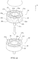
- FIG. 4 a description will be given of a coupling method when the medium pipe-type block 20 is detachably coupled to another medium pipe-type block 20' as the second toy block having the same structure .
- another medium pipe-type block 20' to be coupled to the medium pipe-type block 20 includes a flat surface 25c on which male parts 21e and 21f and female parts 22e and 22f are formed. Consequently, when the medium pipe-type block 20 is coupled to another medium pipe-type block 20', the male parts 21c and 21d on the second flat surface 25b of the medium pipe-type block 20 are engaged with the female parts 22e and 22f on the flat surface 25c of another medium pipe-type block 20'.
- the male parts 21c and 21d of the medium pipe-type block 20 are fitted into the female parts 22e and 22f of another medium pipe-type block 20' such that it is difficult to detach the male parts 21c and 21d unless a specific pulling force is applied thereto.
- the male parts 21c and 21d of the medium pipe-type block 20 can move in the arc-shaped pattern along the extension direction of the female parts 22e and 22f in a state in which the male parts 21c and 21d are fitted into the female parts 22e and 22f of another medium pipe-type block 20'.
- the male parts 21e and 21f on the flat surface 25c of another medium pipe-type block 20' are fitted into the female parts 22c and 22d on the second flat surface 25b of the medium pipe-type block 20. It is difficult to detach the male parts 21e and 21f of another medium pipe-type block 20' from the female parts 22c and 22d of the medium pipe-type block 20 unless a specific pulling force is applied thereto, and the male parts 21e and 21f can move in the arc-shaped pattern circumferentially along the female parts 22c and 22d.
- the medium pipe-type block 20 is capable of appropriately changing the linking position relative to the flat surface 25c of another medium pipe-type block 20'.
- a front view in Fig. 7A and a rear view in Fig. 7B are symmetrical.
- the large pipe-type block 30 as the first toy block has an annular portion 36 having a substantially annular shape. At both ends of the annular portion 36, a substantially annular first flat surface 35a and a substantially annular second flat surface 35b are formed in parallel with each other. That is, the periphery of each of the first flat surface 35a and the second flat surface 35b is circular. Note that the size of the outer diameter of the first flat surface 35a or the second flat surface 35b of the large pipe-type block 30 is larger than the size of the outer diameter of the first flat surface 25a or the second flat surface 25b of the medium pipe-type block 20.
- male parts 31a, 31b, and 31c as three columnar projecting parts are provided so as to be spaced apart from each other at intervals of 120°, and project and extend to the X direction positive side.
- female parts 32a, 32b, and 33c as three arc-shaped slender strip-like depressed parts are formed between the male parts 31a, 31b, and 31c.
- the female parts 32a, 32b, and 33c are formed so as to be indented in the X direction negative side relative to the first flat surface 25a.
- the second flat surface 35b also has the same shape as that of the first flat surface 35a.
- three male parts 31d, 31e, and 31f and three female parts 32d, 32e, and 32d having the same shapes as those of the male parts 31a, 31b, and 31c and the female parts 32a, 32b, and 32c on the first flat surface 35a are formed. That is, the male parts 31d, 31e, and 31f and the female parts 32d, 32e, and 32f are also provided so as to be disposed on the same circumference.
- positions of the male parts 31a, 31b, and 31c and the female parts 32a, 32b, and 32c on the first flat surface 35a are different in phase from the positions of the male parts 31d, 31e, and 31f and the female parts 32d, 32e, and 32f on the second flat surface 35b by 180°.
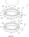
- another large pipe-type block 30' to be coupled to the large pipe-type block 30 includes a flat surface 35c on which male parts 31g, 31h, and 31i and female parts 32g, 32h, and 32i are formed.
- the male parts 31d, 31e, and 31f on the second flat surface 35b of the large pipe-type block 30 are engaged with the female parts 32g, 32h, and 32i on the flat surface 35c of another large pipe-type block 30'.
- the male parts 31d, 31e, and 31f of the large pipe-type block 30 are fitted into the female parts 32g, 32h, and 32i of another large pipe-type block 30' such that it is difficult to detach the male parts 31d, 31e, and 31f unless the specific pulling force is applied thereto.
- the male parts 31d, 31e, and 31f of the large pipe-type block 30 can move in the arc-shaped pattern circumferentially along the female parts 32g, 32h, and 32i in a state in which the male parts 31d, 31e, and 31f are fitted into the female parts 32g, 32h, and 32i of another large pipe-type block 30'.
- the male parts 31g, 31h, and 31i on the flat surface 35c of another large pipe-type block 30' are fitted into the female parts 32d, 32e, and 32f on the second flat surface 35b of the large pipe-type block 30.
- the large pipe-type block 30 is capable of appropriately changing the linking position relative to the flat surface 35c of another large pipe-type block 30'.
- the coupling method of each of the small pipe-type block 10, the medium pipe-type block 20, and the large pipe-type block 30 is not limited to the above-described method in which the toy blocks of the same type are linked one by one.
- the coupling method is not limited to the coupling method shown in each of Figs. 8 and 9 and, the small pipe-type block 10 and the medium pipe-type block 20 may be linked together and the medium pipe-type block 20 and the large pipe-type block 30 may also be linked together.
- the medium reducer-type block 40 has a small-diameter flat surface 45a that has a circular periphery at one end, and a large-diameter flat surface 45b that has an outer diameter larger than that of the small-diameter flat surface 45a and has a circular periphery at the other end.
- the small-diameter flat surface 45a has the same structure as that of the first flat surface 15a or the second flat surface 15b of the small pipe-type block 10, and has male parts 41a and 41b as a pair of substantially columnar projecting parts and female parts 42a and 42b as a pair of arc-shaped strip-like depressed parts.
- the male parts 41a and 41b project and extend vertically relative to the small-diameter flat surface 45a, and the female parts 42a and 42b are formed so as to be vertically indented in a direction opposite to the projection direction of the male parts 41a and 41b relative to the small-diameter flat surface 45a.
- the large-diameter flat surface 45b has a substantially annular shape having the same structure as that of the first flat surface 25a or the second flat surface 25b of the medium pipe-type block 20, and has male parts 41c and 41d as a pair of columnar projecting parts and female parts 42c and 42d as a pair of arc-shaped slender strip-like depressed parts .
- the male parts 41c and 41d also project and extend vertically relative to the large-diameter flat surface 45b, and the female parts 42c and 42d are formed so as to be vertically indented in a direction opposite to the projection direction of the male parts 41c and 41d relative to the large-diameter flat surface 45b.
- a side surface 46 of the medium reducer-type block 40 has a smooth substantially dome-like shape that is spread from the small-diameter flat surface 45a toward the large-diameter flat surface 45b.
- the small pipe-type block 10 can be linked to the small-diameter flat surface 45a of the medium reducer-type block 40, and the medium pipe-type block 20 can be linked to the large-diameter flat surface 45b. That is, the small pipe-type block 10 and the medium pipe-type block 20 that have different diameters are smoothly connected via the medium reducer-type block 40.
- the medium cap-type block 50 has an annular flat surface 55a having an annular shape at one end, and a circular flat surface 55b at the other end.
- the annular flat surface 55a has the same structure as that of the first flat surface 25a or the second flat surface 25b of the medium pipe-type block 20, and has male parts 51a and 51b as a pair of columnar projecting parts and female parts 52a and 52b as a pair of arc-shaped strip-like depressed parts.
- the male parts 51a and 51b project and extend vertically relative to the annular flat surface 55a
- the female parts 52a and 52b are formed so as to be vertically indented in a direction opposite to the projection direction of the male parts 51a and 51b relative to the annular flat surface 55a.
- two holes 58 are formed in the central portion of the medium cap-type block 50.
- the small elbow-type (90 degrees) block 60a in Fig. 12A has a tubular shape that is bent 90 degrees, and flat surfaces 65a and 65b each having male parts and female parts that have the same structures as those of the male parts and the female parts on the first flat surface 15a or the second flat surface 15b of the small pipe-type block 10 are formed at both ends of the small elbow-type block 60a. That is, the flat surfaces 65a and 65b are disposed in different directions that are perpendicular to each other.
- the length of the small elbow-type (45 degrees) block 60b shown in Fig. 12B is shorter than the length of the small elbow-type (90 degrees) block 60a, and the small elbow-type block 60b has a tubular shape that is bent 45 degrees.
- flat surfaces 65c and 65d each having male parts and female parts that have the same structures as those of the male parts and the female parts on the first flat surface 15a or the second flat surface 15b of the small pipe-type block 10 are formed. That is, the flat surface 65c and the flat surface 65d are disposed so as to extend in different directions that form an angle of 45 degrees.
- the toy block shown in Fig. 13A is a small tee-type block 70
- the small tee-type block 70 has a shape in which a cylindrical part 70a and another cylindrical part 70b are combined at right angles and part of the cylindrical part 70b is buried in the center of the cylindrical part 70a.
- a first flat surface 75a and a second flat surface 75b that are disposed in parallel with each other are formed.
- a third flat surface 75c is formed at an end of the cylindrical part 70b. That is, the first flat surface 75a or the second flat surface 75b and the third flat surface 75c are disposed in different directions that are perpendicular to each other.
- each of the first flat surface 75a, the second flat surface 75b, and the third flat surface 75c have male parts and female parts having the same structures as those of the male parts and the female parts on the first flat surface 15a or the second flat surface 15b of the small pipe-type block 10.
- the toy block shown in Fig. 13B is a small cross-type (180 degrees) block 80, and the small cross-type block 80 has a cross shape in which a cylindrical part 80a and another cylindrical part 80b are combined at right angles at central portions thereof.
- Flat surfaces 85a and 85b that are disposed in parallel with each other are formed at both ends of the cylindrical part 80a, and flat surfaces 85c and 85d are formed at both ends of the cylindrical part 80b. That is, the flat surfaces 85a and 85b of the cylindrical part 80a and the flat surfaces 85c and 85d of the cylindrical part 80b are disposed in different directions that are perpendicular to each other.
- each of the flat surfaces 85a, 85b, 85c, and 85d of the small cross-type (180 degrees) block 80 have male parts and female parts having the same structures as those of the male parts and the female parts on the first flat surface 15a or the second flat surface 15b of the small pipe-type block 10.
- the toy block shown in Fig. 13C is a medium cross-type (90 degrees) block 90, and two cylindrical parts 90b and 90c are provided so as to be spaced apart from each other at an interval of 90 degrees on a peripheral surface of an annular part 90a having the same structure as that of the medium pipe-type block 20.
- annular part 90a At both ends of the annular part 90a, flat surfaces 95a and 95b each having male parts and female parts that have the same structures as those of the male parts and the female parts on the first flat surface 25a or 25b of the medium pipe-type block 20 are formed.
- flat surfaces 95c and 95d each having male parts and female parts that have the same structures as those of the male parts and the female parts on the first flat surface 15a or 15b of the small pipe-type block 10 are formed. That is, the flat surface 95a, the flat surface 95b, and the flat surfaces 95c and 95d are disposed in different directions that are perpendicular to each other.
- a large cap-type (subtype) block 100 as a modification of the cap-type block formed with the male parts and the female parts only on one surface such as the medium cap-type block 50 shown in each of Figs. 11A to 11C .
- the large cap-type (subtype) block 100 is a substantially dish-shaped toy block, and has an annular flat surface 105a having an annular shape and a bottom flat surface 105b surrounded by the annular flat surface 105a on one surface.
- a surface opposite to the bottom flat surface 105b serves as a lid surface 107.
- the annular flat surface 105a has the same shape as that of the first flat surface 35a or the second flat surface 35b of the large pipe-type block 30, and has three male parts 101a, 101b, and 101c and three female parts 102a, 102b, and 102c that have the same structures as those of the male parts and the female parts on the first flat surface 35a or the second flat surface 35b thereof.
- the male parts 101a, 101b, and 101c project and extend vertically relative to the annular flat surface 105a
- the female parts 102a, 102b, and 102c are formed so as to be vertically indented in a direction opposite to the projection direction of the male parts 101a, 101b, and 101c relative to the annular flat surface 105a.
- the male parts 101a, 101b, and 101c and the female parts 102a, 102b, and 102c are provided on the same circumference.
- attachment parts 106 each having, as a unit, a pair of male parts 106a, a pair of female parts 106b, and an attachment hole 106c are formed.
- the pair of male parts 106a and the pair of female parts 106b of the attachment part 106 have the same shapes as those of the male parts 11a to 11d and the female parts 12a to 12d of the first flat surface 15a or the second flat surface 15b of the small pipe-type block 10.
- the pair of male parts 106a project and extend vertically relative to the bottom flat surface 105b, and the pair of female parts 106b are formed so as to be vertically indented in a direction opposite to the extension direction of the male parts 106a relative to the bottom flat surface 105b.
- the pair of male parts 106a and the pair of female parts 106b of each attachment part 106 are provided on the same circumference.
- the medium pipe-type block 20, the medium reducer-type block 40, two small pipe-type blocks 10, the small elbow-type (90 degrees) block 60a, and the small elbow-type (45 degrees) block 60b are coupled together in this order from the top. Note that the two small pipe-type blocks 10 are coupled to each other with their center positions displaced from each other.
- Fig. 15B is an example in which the small pipe-type block 10 is coupled to each of the three flat surfaces 75a, 75b, and 75c of the small tee-type block 70.
- Fig. 15C is an example in which the medium pipe-type block 20 is coupled to the annular part 90a of the medium cross-type (90 degrees) block 90, and the small tee-type block 70 is coupled to the cylindrical part 90b.
- the doll 200 includes a face part 201, a body 202 that is connected to the face part 201, and four legs 203 that are attached to the body 202.
- a pair of ears 201a are attached to the face part 201.
- the face part 201 includes the ears 201a, a substantially columnar face front part 201b that is attached to the front side beyond the ears 201a, and a substantially columnar face rear part 201d that is attached to the rear side behind the ears 201a. Further, in addition to them, the face part 201 includes a nose 201c that is attached to the lower half of the face front part 201b, and spacers 201e that are provided between the face front part 201b and the face rear part 201d.
- the ear 201a is obtained by linking two medium cap-type blocks 50 together.
- Each of the face front part 201b and the face rear part 201d is obtained by linking a large cap-type block 50b larger in dimeter than the medium cap-type block 50 to the large pipe-type block 30.
- a pin 2 that represents an eye of the bear is inserted into a linking hole of the large cap-type block 50b of the face front part 201b.
- the nose 201c is obtained by combining the medium pipe-type block 20, the medium cap-type block 50, and a small cap-type block 50a smaller in diameter than the medium cap-type block 50.
- Each spacer 201e is obtained by combining two small cap-type blocks 50a.
- the ear 201a and the spacer 201e between the face front part 201b and the face rear part 201d are attached to the large pipe-type blocks 30 at the front and rear thereof using pins 3.
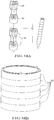
- Fig. 18A it is also possible to form a structure of a mechanical pencil by linking a plurality of the small pipe-type blocks 10 together.
- Fig. 18B it is also possible to form general merchandise such as a pouch by stacking the large pipe-type blocks 30.
- a dynamic structure that freely moves the small pipe-type block 10 linearly by fitting the male parts of the small pipe-type block 10 into rail-like grooves 4a or 4b that are formed in a plate-like block 4 such that the grooves 4a and 4b are orthogonal to each other.
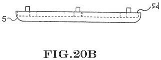
- Figs. 20A and 20B it is also possible to move the small pipe-type block 10 in an arc-shaped pattern by fitting the male parts of the small pipe-type block 10 into three pairs of rail-like grooves 5a, 5b, and 5c that are formed in an annular edge part 5d of a dish-shaped block 5.
- the male part and the female part formed on the flat surface of the toy block are provided on the same circumference, and hence it is possible to link the flat surfaces as the linking surfaces of the toy blocks together at a variety of angles as compared with the case where the male part and the female part are linearly disposed. Accordingly, flexibility in forming by combining the toy blocks is increased.
- the toy block is capable of not only the rotational movement but also linear movement or arc-shaped movement along the rail-like grooves of another member as shown in Fig. 19 and Fig. 20A , and hence it is possible to form a dynamic structure predicated on the capability of partial movement.
- each toy block includes the male part and the female part on one flat surface, and hence a user can link another toy block from any flat surface without considering the orientation of the toy block. Accordingly, a linking member for linking the toy blocks together is not necessary, and it is possible to reduce the number of components of the entire assembly toy.
- the male part of each of the various toy blocks is the columnar projecting part
- the female part thereof is the depressed part formed into the strip-like shape
- the male part is fittable into the female part in the width direction of the female part, and hence it is difficult to detach the toy blocks from each other unless the specific pulling force is applied thereto.
- the female part is the arc-shaped depressed part, whereby it is possible to cause the male part and the female part of the toy blocks to fit together to allow smooth rotational movement and, after the user assembles the toy blocks, a twist operation for adjusting the shape of the assembled toy blocks is allowed.
- the periphery of the flat surface of each of the various toy blocks is circular, and hence it becomes possible to create a round form as a whole such as the bear-like doll 200 shown in Fig. 16A , the mechanical pencil shown in Fig. 18A , or the pouch shown in Fig. 18B .
- the medium reducer-type block 40 shown in Fig. 10A or the medium cross-type (90 degrees) block shown in Fig. 13C has two or more circular flat surfaces having different outer diameters, and it is thereby possible to connect the toy blocks having different diameters to each other.
- the side surface 46 of the medium reducer-type block 40 is a smoothly curved surface, and hence it is possible to smoothly connect the toy blocks having different diameters via the medium reducer-type block 40.
- each of the various toy blocks has a pair of the flat surfaces that are disposed in parallel with each other, and hence it is possible to linearly link a plurality of the toy blocks together.
- the small elbow-type (90 degrees) block 60a shown in Fig. 12A has two or more flat surfaces disposed in different directions. With this, it is possible to link the toy blocks in various directions to allow more diversified three-dimensional forming.
- the male part of the toy block is the columnar projecting part, but the male part may also have a prism shape or other prismatic shapes. Further, the shape of the flat surface formed in the toy block is not limited to the circular shape and may also be an oblong shape.
- an optical fiber may be provided in a through hole or an opening formed in the toy block.
- the shape of the female part formed in the toy block for the assembly toy is not limited to the slender strip-like groove, and the female part may also be a depressed part having a circular cross section, as shown in Fig. 21 or 22 .
- a substantially annular first flat surface 235a and a substantially annular second flat surface 235b are formed in parallel with each other. That is, the periphery of each of the first flat surface 235a and the second flat surface 235b is circular.
- male parts 231 as five columnar projecting parts are provided so as to be spaced apart from each other at regular intervals along the shape of the first flat surface 235a, and project and extend to the X direction positive side.
- three female parts 232 as depressed parts each having a circular cross section are formed so as to be indented in the X direction negative side. That is, on the first flat surface 235a, an arrangement of one male part 231 and three female parts 232 is disposed five times repeatedly along the circumferential direction of the first flat surface 235a. Consequently, on the first flat surface 235a, a total of fifteen depressed parts are provided. Five male parts 231 and fifteen female parts 232 are provided so as to be disposed on the same circumference.
- the second flat surface 235b also has the same shape as that of the first flat surface 235a, and has five male parts 231 and fifteen female parts 232.
- the toy block 230 as the first toy block can be coupled to another toy block 230' as the second toy block having the same structure.
- the male part 231 on the second flat surface 235b of the first toy block 230 is detachably fitted into the female part 232 on a flat surface 235c of the second toy block 230'.
- the male part 231 on the flat surface 235c of the second toy block 230' is detachably fitted into the female part 232 on the second flat surface 235b of the first toy block 230.
- the first toy block 230 may be coupled to the second toy block 230' at any angle.
- a substantially annular first flat surface 335a and a substantially annular second flat surface 335b are formed in parallel with each other. That is, the periphery of each of the first flat surface 335a and the second flat surface 335b is circular.
- male parts 331 as ten columnar projecting parts and ten female parts 332 as depressed parts each having a circular cross section are alternately disposed side by side along the shape of the first flat surface 335a.
- the male part 331 projects and extends in the X direction positive side
- the female part 332 is formed so as to be indented in the X direction negative side.
- the second flat surface 335b also has the same shape as that of the first flat surface 335a, and has ten male parts 331 and ten female parts 332.
- the toy block 330 as the first toy block can be coupled to a toy block 330' as the second toy block having the same structure .
- the male part 331 on the second flat surface 335b of the first toy block 330 is detachably fitted into the female part 332 on a flat surface 335c of the second toy block 330'.
- the male part 331 on the flat surface 335c of the second toy block 330' is detachably fitted into the female part 332 on the second flat surface 335b of the first toy block 330.
- the first toy block 330 may be coupled to the flat surface 335c of the second toy block 330' at any angle.
- the male part and the female part are provided on the same circumference, and hence it is possible to link the flat surfaces of the toy blocks together at a variety of angles.
- the toy blocks are detachably linked together, and hence it is possible to detach the toy blocks that are once coupled together from each other and couple them together again at a different angle to change the linking position.
- the arrangement of one male part 231 and three female parts 232 larger in number than the male part 231 is disposed five times repeatedly. Accordingly, it is possible to link the first toy block 330 to the second toy block 330' at a greater variety of angles while changing the angle gradually.
- the arrangement of the male part 231 and the female parts 232 provided on the first flat surface 235a or the second flat surface 235b of the toy block 230 is not limited to the arrangement of the combination of one male part and a plurality of the female parts larger in number than the male part. That is, on the first flat surface 235a or the second flat surface 235b of the toy block 230, the arrangement constituted by two or more male parts and a plurality of the female parts larger in number than the male parts may be repeatedly provided.
- the male parts 331 and the female parts 332 are alternately disposed on the same circumference, and hence, similarly to the toy block 230, it is possible to link the toy blocks 330 together at a variety of angles while adjusting the angle gradually.
- the shape of the female part formed in the toy block for the assembly toy may also be a depressed part having a strip-like shape in which a plurality of circles having the same diameter are consecutively formed on the circumference so as to overlap each other.
- a substantially annular first flat surface 435a and a substantially annular second flat surface 435b shown in Fig. 23A are formed in parallel with each other. That is, the periphery of each of the first flat surface 435a and the second flat surface 435b is circular.
- male parts 431 as three columnar projecting parts are provided so as to be spaced apart from each other at intervals of 120° along the shape of the first flat surface 435a, and project and extend to the X direction positive side. Between the three male parts 431, female parts 432 as strip-like depressed parts are formed.
- Each female part 432 is a depressed part having a strip-like shape in which twelve circles 432a having the same diameter are consecutively formed on the circumference so as to overlap each other, and is formed so as to be indented to the X direction negative side. Each circle 432a is formed so as to allow the male part 431 to detachably fit into the circle 432a.
- the second flat surface 435b also has the same shape as that of the first flat surface 435a, and has three male parts 431 and three female parts 432.
- the toy block 430 as the first toy block can be coupled to another toy block 430' as the second toy block having the same structure.
- the male part 431 on the second flat surface 435b of the first toy block 430 is detachably fitted into the female part 432 on a flat surface 435c of the second toy block 430'.
- the male part 431 on the flat surface 435c of the second toy block 430' is detachably fitted into the female part 432 on the second flat surface 435b of the first toy block 430.
- the female part 432 has the shape in which twelve circles 432a are consecutively formed, and hence the male part 431 is fitted at the position corresponding to each circle 432a, and the position thereof is fixed.
- each male part 431 can move along the extension direction of the female part 432 in a state in which each male part 431 is fitted into each female part 432.
- the male part 431 fitted at the position corresponding to the circle 432a of the female part 432 can move to the position corresponding to another circle 432a adjacent to the above circle 432a by application of a force at a predetermined level or higher in the extension direction of the female part 432 to the male part 431.
- the male part 431 and the female part 432 are provided on the same circumference, and hence it is possible to link the second flat surface 435b of the first toy block 430 to the flat surface 435c of the second toy block 430' at a variety of angles.
- the male part 431 of the toy block 430 can move in the extension direction of the female part 432 in the state in which the male part 431 is fitted into the female part 432. Accordingly, the first toy block 430 can rotate relative to the second toy block 430' while a state in which the first toy block 430 is linked to the second toy block 430' is maintained, and change the linking position.
- the male part 431 is fixed to the position corresponding to the circle 432a of the female part 432 unless a force at a specific level or higher is applied to the toy block 430, and hence the first toy block 430 and the second toy block 430' can be stably coupled to each other.
Landscapes
- Toys (AREA)
Description
- The invention relates to an assembly toy according to the preamble of
claim 1. - Conventionally, there are assembly toys that are played with by linking a plurality of blocks together to form various shapes. For example,
PTL 1 describes a block assembly toy with which various shapes are three-dimensionally formed by alternately engaging depressed parts and projecting parts of a plurality of substantially cubic blocks each having projections and depressions on their six surfaces. Herein, the projecting parts and the depressed parts formed on each of the six surfaces of the block are constituted as a male part and a female part for linking the blocks together. - [PTL 1] Japanese Patent No.
3567267 - However, in the block assembly toy in
PTL 1, when the blocks are linked together, the surface of one block can be combined with the projection and the depression formed on the surface of another block only at a predetermined angle. That is, it is not possible to link the blocks together at a variety of angles. Accordingly, flexibility in forming by combining the blocks is limited.
US-A-3670449 disclose an assembly toy with features according to the preamble ofclaim 1. - The invention has been made in order to solve such a problem, and an object thereof is to provide an assembly toy capable of linking the linking surfaces of a plurality of toy blocks each having a male part and a female part on at least one surface together at a variety of angles.
- The invention is defined in
claim 1. Further developments are given in the dependent claims.
The present disclosure contains several examples and embodiments of the present invention, which are both described as embodiments or as assembly toys. However, only the embodiments ofFig. 13A ,15B and15C and the corresponding parts of the description are covered by the claims and therefore considered as embodiments of the invention. - The assembly toy can be an assembly toy having a first toy block and a second toy block linkable to each other, wherein each of the toy blocks includes: at least one flat surface; a male part that projects and extends vertically from the flat surface; and a female part that is formed so as to be vertically indented from the flat surface in a direction opposite to the projection direction of the male part, the male part and the female part are provided on the same circumference on the flat surface, and the male part of the first toy block detachably fits into the female part of the second toy block and the male part of the second toy block detachably fits into the female part of the first toy block to allow the first toy block and the second toy block to link to each other and allow the first toy block to change a linking position relative to the second toy block.
- In addition, in the assembly toy, the first toy block may be movable relative to the second toy block while the state in which the first toy block and the second toy block are linked together is maintained.
- Further, the male part of the toy block for the assembly toy may have a columnar projecting part that projects from the flat surface, the female part may have a depressed part that is formed into an arc-shaped strip-like shape on the flat surface, the projecting part of the male part may be fittable into the depressed part of the female part in a width direction of the depressed part, and the projecting parts of the male parts of the first toy block and the second toy block may move along the depressed parts of the female parts of the first toy block and the second toy block while the state in which the first toy block and the second toy block are linked together is maintained to allow the first toy block to rotate relative to the second toy block.
- In addition, the male part and the female part may be alternately disposed on the same circumference.
- Further, the male part and the female part may be disposed on the same circumference by repeating an arrangement of at least one of the male parts and a plurality of the female parts larger in number than the male part.
- According to the assembly toy according to the invention, it is possible to link the linking surfaces of a plurality of the toy blocks each having the male part and the female part on at least one surface together at a variety of angles.
-
-
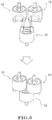
Fig. 1 is a perspective view showing a small pipe-type block as an example of a toy block for an assembly toy according to an embodiment, and is a view showing a state in which two small pipe-type blocks are coupled to each other. -
Fig. 2 is a plan view showing a detailed shape of a first flat surface of the small pipe-type block shown inFig. 1 . -
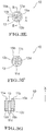
Fig. 3A is a front view of the small pipe-type block shown inFig. 1 . -
Fig. 3B is a rear view of the small pipe-type block shown inFig. 1 . -
Fig. 3C is a left side view of the small pipe-type block shown inFig. 1 . -
Fig. 3D is a right side view of the small pipe-type block shown inFig. 1 . -
Fig. 3E is a plan view of the small pipe-type block shown inFig. 1 . -
Fig. 3F is a bottom view of the small pipe-type block shown inFig. 1 . -
Fig. 3G is a cross-sectional view of the small pipe-type block shown inFig. 1 taken along the line A-A shown inFig. 3E . -
Fig. 3H is a cross-sectional view of the small pipe-type block shown inFig. 1 taken along the line B-B shown inFig. 3E . -
Fig. 3I is a reference perspective view of the small pipe-type block shown inFig. 1 . -
Fig. 4 is a perspective view showing a medium pipe-type block as an example of the toy block for the assembly toy according to an embodiment, and is a view showing a state in which two medium pipe-type blocks are coupled to each other. -
Fig. 5A is a front view of the medium pipe-type block shown inFig. 4 . -
Fig. 5B is a rear view of the medium pipe-type block shown inFig. 4 . -
Fig. 5C is a left side view of the medium pipe-type block shown inFig. 4 . -
Fig. 5D is a right side view of the medium pipe-type block shown inFig. 4 . -
Fig. 5E is a plan view of the medium pipe-type block shown inFig. 4 . -
Fig. 5F is a bottom view of the medium pipe-type block shown inFig. 4 . -
Fig. 5G is a cross-sectional view of the medium pipe-type block shown inFig. 4 taken along the line A-A shown inFig. 5E . -
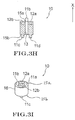
Fig. 5H is a cross-sectional view of the medium pipe-type block shown inFig. 4 taken along the line B-B shown inFig. 5E . -
Fig. 5I is a reference perspective view of the medium pipe-type block shown inFig. 4 . -
Fig. 6 is a perspective view showing a large pipe-type block as an example of the toy block for the assembly toy according to an embodiment, and is a view showing a state in which two large pipe-type blocks are coupled to each other. -
Fig. 7A is a front view of the large pipe-type block shown inFig. 6 . -
Fig. 7B is a rear view of the large pipe-type block shown inFig. 6 . -
Fig. 7C is a left side view of the large pipe-type block shown inFig. 6 . -
Fig. 7D is a right side view of the large pipe-type block shown inFig. 6 . -
Fig. 7E is a plan view of the large pipe-type block shown inFig. 6 . -
Fig. 7F is a bottom view of the large pipe-type block shown inFig. 6 . -
Fig. 7G is a cross-sectional view of the large pipe-type block shown inFig. 6 taken along the line A-A shown inFig. 7E . -
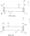
Fig. 7H is a cross-sectional view of the large pipe-type block shown inFig. 6 taken along the line B-B shown inFig. 7E . -
Fig. 7I is a cross-sectional view of the large pipe-type block shown inFig. 6 taken along the line C-C shown inFig. 7E . -
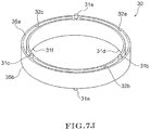
Fig. 7J is a reference perspective view of the large pipe-type block shown inFig. 6 . -
Fig. 8 is a view showing a state in which three small pipe-type blocks shown inFig. 1 are coupled together with their center positions displaced from each other. -
Fig. 9 is a view showing a state in which the small pipe-type block shown inFig. 1 is coupled to the large pipe-type block shown inFig. 6 . -
Fig. 10A is a perspective view showing a medium reducer-type block as an example of the toy block for the assembly toy according to an embodiment. -
Fig. 10B is a plan view of the medium reducer-type block shown inFig. 10A . -
Fig. 10C is a bottom view of the medium reducer-type block shown inFig. 10A . -
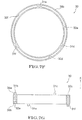
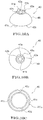
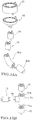
Fig. 11A is a perspective view showing a medium cap-type block as an example of the toy block for the assembly toy according to an embodiment. -
Fig. 11B is a plan view of the medium cap-type block shown inFig. 11A . -
Fig. 11C is a bottom view of the medium cap-type block shown inFig. 11A . -
Fig. 12A is a perspective view showing a small elbow-type (90 degrees) block as an example of the toy block for the assembly toy according to an embodiment. -
Fig. 12B is a perspective view showing a small elbow-type (45 degrees) block as an example of the toy block for the assembly toy according to an embodiment. -
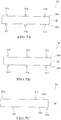
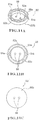
Fig. 13A is a perspective view showing a small tee-type block as an example of the toy block for the assembly toy according to an embodiment of the invention. -
Fig. 13B is a perspective view showing a small cross-type (180 degrees) block as an example of the toy block for the assembly toy according to an embodiment. -
Fig. 13C is a perspective view showing a medium cross-type (90 degrees) block as an example of the toy block for the assembly toy according to an embodiment. -
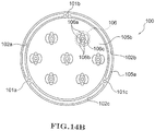
Fig. 14A is a side view showing a large cap-type (subtype) block as an example of the toy block for the assembly toy according to an embodiment. -
Fig. 14B is a bottom view of the large cap-type (subtype) block shown inFig. 14A . -
Fig. 15A is a perspective view showing an example of a combination when various types of the toy blocks according to an embodiment are coupled together. -
Fig. 15B is a perspective view showing an example of the combination when various types of the toy blocks (including the inventive toy block according toFig. 13A ) are coupled together. -
Fig. 15C is a perspective view showing an example of the combination when various types of the toy blocks (including the inventive toy block according toFig. 13A ) are coupled together. -
Fig. 16A is a perspective view showing an example in which a bear-like doll is assembled by using various types of the toy blocks according to an embodiment. -
Fig. 16B is a front view of the bear-like doll shown inFig. 16A . -
Fig. 16C is a perspective view showing a state in which orientations of the face and feet of the bear-like doll shown inFig. 16A are changed. -
Fig. 17A is a perspective view of a portion of the face of the bear-like doll shown inFig. 16A . -
Fig. 17B is a side view of the portion of the face of the bear-like doll shown inFig. 16A . -
Fig. 17C is an exploded view of the portion of the face of the bear-like doll shown inFig. 16A . -
Fig. 18A is a view showing an example in which the toy block for the assembly toy according to an embodiment is applied for use as general merchandise. -
Fig. 18B is a view showing an example in which the toy block for the assembly toy according to an embodiment is applied for use as general merchandise. -
Fig. 19 is a perspective view showing an example of the mode of assembly of the toy block for the assembly toy according to an embodiment by showing displacement. -
Fig. 20A is a perspective view showing an example of the mode of assembly of the toy block for the assembly toy according to an embodiment by showing displacement. -
Fig. 20B is a side view showing another block to which the toy block according to an embodiment is coupled in the mode of the assembly shown inFig. 20A . -
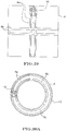
Fig. 21 is a perspective view showing the toy block for the assembly toy shown as another example, and is a view showing a state in which two toy blocks are coupled to each other. -
Fig. 22 is a perspective view showing the toy block for the assembly toy shown as another example, and is a view showing a state in which two toy blocks are coupled to each other. -
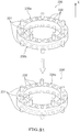
Fig. 23A is a plan view showing the toy block for the assembly toy shown as another example. -
Fig. 23B is a perspective view showing a state in which the toy blocks shown inFig. 23A are coupled to each other. - Hereinbelow, an embodiment of the invention will be described based on the accompanying drawings. Note that an assembly toy in the invention is a toy for forming structures having various shapes by detachably combining the various toy blocks describe below.
- First, based on
Figs. 1 and 2 and Figs. 3A to 3I , a description will be given of a small pipe-type block 10 as the toy block for the assembly toy. Note that a front view inFig. 3A and a rear view inFig. 3B are symmetrical, and a left side view inFig. 3C and a right side view inFig. 3D are symmetrical. - Referring to
Fig. 1 , the small pipe-type block 10 as a first toy block has acylindrical portion 16 having a substantially cylindrical shape. At both ends of thecylindrical portion 16, a circular firstflat surface 15a and a circular secondflat surface 15b are formed in parallel with each other. Herein, a throughhole 13 is formed in the central portion of the firstflat surface 15a, and extends in an axial direction of the small pipe-type block 10. On the firstflat surface 15a,male parts hole 13 project and extend vertically from the firstflat surface 15a. - Note that, in the following description, it is assumed that the projection direction in which the male part projects vertically relative to the first flat surface is an X direction positive side, and the direction opposite to the X direction positive side is an X direction negative side.
- Between the
male parts female parts hole 13. As shown inFig. 2 , thefemale part 12a is a depressed part having a shape in whichsemicircular parts like part 121 having an arc-shaped slender strip-like shape, and is formed so as to be vertically indented from the firstflat surface 15a in the X direction negative side. Similarly, thefemale part 12b is a depressed part having a shape in whichsemicircular parts like part 124 having an arc-shaped slender strip-like shape, and is formed so as to be indented in the X direction negative side. That is, a pair of thefemale parts flat surface 15a. Note that the length of each of thefemale parts male parts male parts female parts - The second
flat surface 15b has the same shape as that of the firstflat surface 15a. That is, on the secondflat surface 15b as well, a pair ofmale parts female parts male parts female parts flat surface 15a are formed. Herein, thefemale parts flat surface 15b in the X direction positive side that is opposite in direction to the X direction negative side as the projection direction of themale parts male parts female parts Figs. 3E and 3F , the positions of themale parts female parts flat surface 15a are different in phase from the positions of themale parts female parts flat surface 15b by 90°. - Next, a description will be given of a coupling method when, as shown in
Fig. 1 , the small pipe-type block 10 is coupled to another small pipe-type block 10' as a second toy block having the same structure. - Note that another small pipe-type block 10' to be coupled to the small pipe-
type block 10 includes, similarly to the small pipe-type block 10, aflat surface 15c on whichmale parts female parts type block 10 is coupled to another small pipe-type block 10', themale parts flat surface 15b of the small pipe-type block 10 are engaged with thefemale parts flat surface 15c of another small pipe-type block 10'. Herein, the length in the width direction of each of thefemale parts flat surface 15c of another small pipe-type block 10' is substantially identical to the diameter of each of themale parts flat surface 15b of the small pipe-type block 10. Accordingly, themale parts type block 10 are fitted into and attached to thefemale parts female parts male parts type block 10 can move in an arc-shaped pattern circumferentially along thefemale parts male parts female parts - In addition, the
male parts flat surface 15c of another small pipe-type block 10' are engaged with thefemale parts flat surface 15b of the small pipe-type block 10 by the same method as that for the engagement between themale parts female parts female parts flat surface 15b of the small pipe-type block 10 is also substantially identical to the diameter of each of themale parts flat surface 15c of another small pipe-type block 10'. Consequently, themale parts female parts male parts female parts type block 10. Therefore, after the small pipe-type block 10 and another small pipe-type block 10' are coupled to each other, it is possible to rotate the small pipe-type block 10 and another small pipe-type block 10' relative to each other as indicated by an arrow inFig. 1 while maintaining the linked state. That is, the small pipe-type block 10 is capable of appropriately changing the linking position relative to theflat surface 15c of another small pipe-type block 10'. - Note that, in the case where the small pipe-
type block 10 and another small pipe-type block 10' that are coupled to each other are pulled with a specific force, it is possible to detach the small pipe-type block 10 and another small pipe-type block 10' from each other. That is, the small pipe-type block 10 and another small pipe-type block 10' are detachably coupled to each other. - Next, based on
Fig. 4 and Figs. 5A to 5I , a description will be given of a medium pipe-type block 20 as the toy block for the assembly toy. Note that a front view inFig. 5A and a rear view inFig. 5B are symmetrical, and a left side view inFig. 5C and a right side view inFig. 5D are symmetrical. - The medium pipe-
type block 20 as the first toy block has acylindrical portion 26 having a substantially cylindrical shape. At both ends of thecylindrical portion 26, a firstflat surface 25a and a secondflat surface 25b as substantially annular flat surfaces are formed in parallel with each other. That is, the periphery of each of the firstflat surface 25a and the secondflat surface 25b is circular. Note that the size of the outer diameter of the firstflat surface 25a or the secondflat surface 25b of the medium pipe-type block 20 is larger than the size of the outer diameter of the firstflat surface 15a or the secondflat surface 15b of the small pipe-type block 10. Herein, acircular opening 23 is formed in the central portion of the firstflat surface 25a. On the firstflat surface 25a,male parts opening 23 project and extend to the X direction positive side. In addition, between a pair of themale parts female parts flat surface 25a are formed. That is, themale parts female parts Figs. 5G and 5H , thefemale parts flat surface 25a. The secondflat surface 25b also has the same shape as that of the firstflat surface 25a. Herein, on the secondflat surface 25b, a pair ofmale parts female parts male parts female parts flat surface 25a are formed. That is, themale parts female parts male parts female parts flat surface 25a are different in phase from the positions of themale parts female parts flat surface 25b by 90°. - With reference to
Fig. 4 , a description will be given of a coupling method when the medium pipe-type block 20 is detachably coupled to another medium pipe-type block 20' as the second toy block having the same structure . Note that, similarly to the medium pipe-type block 20, another medium pipe-type block 20' to be coupled to the medium pipe-type block 20 includes aflat surface 25c on whichmale parts female parts type block 20 is coupled to another medium pipe-type block 20', themale parts flat surface 25b of the medium pipe-type block 20 are engaged with thefemale parts flat surface 25c of another medium pipe-type block 20'. Herein, similarly to the small pipe-type block 10, themale parts type block 20 are fitted into thefemale parts male parts male parts type block 20 can move in the arc-shaped pattern along the extension direction of thefemale parts male parts female parts male parts flat surface 25c of another medium pipe-type block 20' are fitted into thefemale parts flat surface 25b of the medium pipe-type block 20. It is difficult to detach themale parts female parts type block 20 unless a specific pulling force is applied thereto, and themale parts female parts type block 20 and another medium pipe-type block 20' are coupled to each other, it is possible to rotate the medium pipe-type block 20 and another medium pipe-type block 20' relative to each other while maintaining the linked state. That is, the medium pipe-type block 20 is capable of appropriately changing the linking position relative to theflat surface 25c of another medium pipe-type block 20'. - Further, a description will next be given of a large pipe-
type block 30 as the toy block for the assembly toy based onFig. 6 and Figs. 7A to 7J . Note that a front view inFig. 7A and a rear view inFig. 7B are symmetrical. - The large pipe-
type block 30 as the first toy block has anannular portion 36 having a substantially annular shape. At both ends of theannular portion 36, a substantially annular firstflat surface 35a and a substantially annular secondflat surface 35b are formed in parallel with each other. That is, the periphery of each of the firstflat surface 35a and the secondflat surface 35b is circular. Note that the size of the outer diameter of the firstflat surface 35a or the secondflat surface 35b of the large pipe-type block 30 is larger than the size of the outer diameter of the firstflat surface 25a or the secondflat surface 25b of the medium pipe-type block 20. Herein, on the firstflat surface 35a,male parts male parts female parts Figs. 7G to 7I , thefemale parts flat surface 25a. That is, themale parts female parts flat surface 35b also has the same shape as that of the firstflat surface 35a. Herein, on the secondflat surface 35b, threemale parts female parts male parts female parts flat surface 35a are formed. That is, themale parts female parts male parts female parts flat surface 35a are different in phase from the positions of themale parts female parts flat surface 35b by 180°. - With reference to
Fig. 6 , a description will be given of a coupling method when the large pipe-type block 30 is detachably coupled to another large pipe-type block 30' as the second toy block having the same structure. Note that, similarly to the large pipe-type block 30, another large pipe-type block 30' to be coupled to the large pipe-type block 30 includes aflat surface 35c on whichmale parts female parts type block 30 is coupled to another large pipe-type block 30', themale parts flat surface 35b of the large pipe-type block 30 are engaged with thefemale parts flat surface 35c of another large pipe-type block 30'. Herein, similarly to the small pipe-type block 10 or the medium pipe-type block 20, themale parts type block 30 are fitted into thefemale parts male parts male parts type block 30 can move in the arc-shaped pattern circumferentially along thefemale parts male parts female parts male parts flat surface 35c of another large pipe-type block 30' are fitted into thefemale parts flat surface 35b of the large pipe-type block 30. It is difficult to detach themale parts female parts type block 30, and themale parts female parts type block 30 and another large pipe-type block 30' are coupled to each other, it is possible to rotate the large pipe-type block 30 and another large pipe-type block 30' relative to each other while maintaining the linked state. That is, the large pipe-type block 30 is capable of appropriately changing the linking position relative to theflat surface 35c of another large pipe-type block 30'. - The coupling method of each of the small pipe-
type block 10, the medium pipe-type block 20, and the large pipe-type block 30 is not limited to the above-described method in which the toy blocks of the same type are linked one by one. - That is, as shown in
Fig. 8 , it is possible to engage the male parts and the female parts of three small pipe-type blocks 10 after displacing the center positions thereof from each other to thereby couple two of the small pipe-type blocks 10 to one flat surface of the remaining one of the small pipe-type blocks 10. In addition, as shown inFig. 9 , it is also possible to couple the small pipe-type block 10 to one of the flat surfaces of the large pipe-type block 30. - Note that the coupling method is not limited to the coupling method shown in each of
Figs. 8 and9 and, the small pipe-type block 10 and the medium pipe-type block 20 may be linked together and the medium pipe-type block 20 and the large pipe-type block 30 may also be linked together. - Next, with reference to
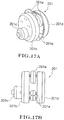
Figs. 10A to 10C , a description will be given of a medium reducer-type block 40 as the toy block. - The medium reducer-
type block 40 has a small-diameterflat surface 45a that has a circular periphery at one end, and a large-diameterflat surface 45b that has an outer diameter larger than that of the small-diameterflat surface 45a and has a circular periphery at the other end. As shown inFig. 10B , the small-diameterflat surface 45a has the same structure as that of the firstflat surface 15a or the secondflat surface 15b of the small pipe-type block 10, and hasmale parts female parts male parts flat surface 45a, and thefemale parts male parts flat surface 45a. In addition, as shown inFig. 10C , the large-diameterflat surface 45b has a substantially annular shape having the same structure as that of the firstflat surface 25a or the secondflat surface 25b of the medium pipe-type block 20, and hasmale parts female parts male parts flat surface 45b, and thefemale parts male parts flat surface 45b. In addition, as shown inFig. 10A , aside surface 46 of the medium reducer-type block 40 has a smooth substantially dome-like shape that is spread from the small-diameterflat surface 45a toward the large-diameterflat surface 45b. Consequently, the small pipe-type block 10 can be linked to the small-diameterflat surface 45a of the medium reducer-type block 40, and the medium pipe-type block 20 can be linked to the large-diameterflat surface 45b. That is, the small pipe-type block 10 and the medium pipe-type block 20 that have different diameters are smoothly connected via the medium reducer-type block 40. - Next, with reference to
Figs. 11A to 11C , a description will be given of a medium cap-type block 50 as the toy block. - The medium cap-
type block 50 has an annularflat surface 55a having an annular shape at one end, and a circularflat surface 55b at the other end. The annularflat surface 55a has the same structure as that of the firstflat surface 25a or the secondflat surface 25b of the medium pipe-type block 20, and hasmale parts female parts male parts flat surface 55a, and thefemale parts male parts flat surface 55a. In addition, twoholes 58 are formed in the central portion of the medium cap-type block 50. - Next, with reference to
Figs. 12A and 12B , a description will be given of a small elbow-type (90 degrees)block 60a and a small elbow-type (45 degrees)block 60b as the toy blocks. - The small elbow-type (90 degrees)
block 60a inFig. 12A has a tubular shape that is bent 90 degrees, andflat surfaces flat surface 15a or the secondflat surface 15b of the small pipe-type block 10 are formed at both ends of the small elbow-type block 60a. That is, theflat surfaces block 60b shown inFig. 12B is shorter than the length of the small elbow-type (90 degrees)block 60a, and the small elbow-type block 60b has a tubular shape that is bent 45 degrees. At both ends of the small elbow-type (45 degrees)block 60b,flat surfaces flat surface 15a or the secondflat surface 15b of the small pipe-type block 10 are formed. That is, theflat surface 65c and theflat surface 65d are disposed so as to extend in different directions that form an angle of 45 degrees. - Further, next, with reference to
Figs. 13A to 13C , a description will be given of the toy blocks having other shapes. - First, the toy block shown in
Fig. 13A is a small tee-type block 70, and the small tee-type block 70 has a shape in which acylindrical part 70a and anothercylindrical part 70b are combined at right angles and part of thecylindrical part 70b is buried in the center of thecylindrical part 70a. At both ends of thecylindrical part 70a, a firstflat surface 75a and a secondflat surface 75b that are disposed in parallel with each other are formed. In addition, at an end of thecylindrical part 70b, a thirdflat surface 75c is formed. That is, the firstflat surface 75a or the secondflat surface 75b and the thirdflat surface 75c are disposed in different directions that are perpendicular to each other. Note that each of the firstflat surface 75a, the secondflat surface 75b, and the thirdflat surface 75c have male parts and female parts having the same structures as those of the male parts and the female parts on the firstflat surface 15a or the secondflat surface 15b of the small pipe-type block 10. - The toy block shown in
Fig. 13B is a small cross-type (180 degrees)block 80, and the smallcross-type block 80 has a cross shape in which acylindrical part 80a and anothercylindrical part 80b are combined at right angles at central portions thereof.Flat surfaces cylindrical part 80a, andflat surfaces cylindrical part 80b. That is, theflat surfaces cylindrical part 80a and theflat surfaces cylindrical part 80b are disposed in different directions that are perpendicular to each other. Herein, each of theflat surfaces block 80 have male parts and female parts having the same structures as those of the male parts and the female parts on the firstflat surface 15a or the secondflat surface 15b of the small pipe-type block 10. - The toy block shown in
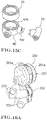
Fig. 13C is a medium cross-type (90 degrees)block 90, and twocylindrical parts annular part 90a having the same structure as that of the medium pipe-type block 20. At both ends of theannular part 90a,flat surfaces flat surface type block 20 are formed. In addition, also at ends of thecylindrical parts flat surfaces flat surface type block 10 are formed. That is, theflat surface 95a, theflat surface 95b, and theflat surfaces - Next, with reference to
Figs. 14A and14B , a description will be given of a large cap-type (subtype) block 100 as a modification of the cap-type block formed with the male parts and the female parts only on one surface such as the medium cap-type block 50 shown in each ofFigs. 11A to 11C . - The large cap-type (subtype) block 100 is a substantially dish-shaped toy block, and has an annular
flat surface 105a having an annular shape and a bottomflat surface 105b surrounded by the annularflat surface 105a on one surface. A surface opposite to the bottomflat surface 105b serves as alid surface 107. The annularflat surface 105a has the same shape as that of the firstflat surface 35a or the secondflat surface 35b of the large pipe-type block 30, and has threemale parts female parts flat surface 35a or the secondflat surface 35b thereof. That is, themale parts flat surface 105a, and thefemale parts male parts flat surface 105a. In addition, themale parts female parts - On the bottom
flat surface 105b, sevenattachment parts 106 each having, as a unit, a pair ofmale parts 106a, a pair offemale parts 106b, and anattachment hole 106c are formed. The pair ofmale parts 106a and the pair offemale parts 106b of theattachment part 106 have the same shapes as those of themale parts 11a to 11d and thefemale parts 12a to 12d of the firstflat surface 15a or the secondflat surface 15b of the small pipe-type block 10. That is, the pair ofmale parts 106a project and extend vertically relative to the bottomflat surface 105b, and the pair offemale parts 106b are formed so as to be vertically indented in a direction opposite to the extension direction of themale parts 106a relative to the bottomflat surface 105b. The pair ofmale parts 106a and the pair offemale parts 106b of eachattachment part 106 are provided on the same circumference. - Next, with reference to
Figs. 15A to 15C , a description will be given of an example of an assembly method of various toy blocks. - In
Fig. 15A , the medium pipe-type block 20, the medium reducer-type block 40, two small pipe-type blocks 10, the small elbow-type (90 degrees)block 60a, and the small elbow-type (45 degrees)block 60b are coupled together in this order from the top. Note that the two small pipe-type blocks 10 are coupled to each other with their center positions displaced from each other. -
Fig. 15B is an example in which the small pipe-type block 10 is coupled to each of the threeflat surfaces type block 70. -
Fig. 15C is an example in which the medium pipe-type block 20 is coupled to theannular part 90a of the medium cross-type (90 degrees)block 90, and the small tee-type block 70 is coupled to thecylindrical part 90b. - In addition, it is also possible to form a bear-
like doll 200 as shown inFig. 16A by combining various toy blocks. - The
doll 200 includes aface part 201, abody 202 that is connected to theface part 201, and fourlegs 203 that are attached to thebody 202. In addition, a pair ofears 201a are attached to theface part 201. As shown inFig. 16B , it is possible to move theears 201a of thedoll 200 relative to theface part 201. In addition, as shown inFig. 16C , it is possible to change the angle and orientation of theface part 201 or theleg 203 of thedoll 200. - A description will be given of the structure of the
face part 201 of the bear-like doll 200 by usingFigs. 17A to 17C . - As shown in
Figs. 17A and 17B , theface part 201 includes theears 201a, a substantially columnar facefront part 201b that is attached to the front side beyond theears 201a, and a substantially columnar facerear part 201d that is attached to the rear side behind theears 201a. Further, in addition to them, theface part 201 includes anose 201c that is attached to the lower half of the facefront part 201b, andspacers 201e that are provided between the facefront part 201b and the facerear part 201d. - A description will be given of the detailed structure of each portion of the
face part 201 with reference toFig. 17C . - First, the
ear 201a is obtained by linking two medium cap-type blocks 50 together. Each of the facefront part 201b and the facerear part 201d is obtained by linking a large cap-type block 50b larger in dimeter than the medium cap-type block 50 to the large pipe-type block 30. A pin 2 that represents an eye of the bear is inserted into a linking hole of the large cap-type block 50b of the facefront part 201b. Thenose 201c is obtained by combining the medium pipe-type block 20, the medium cap-type block 50, and a small cap-type block 50a smaller in diameter than the medium cap-type block 50. Eachspacer 201e is obtained by combining two small cap-type blocks 50a. Theear 201a and thespacer 201e between the facefront part 201b and the facerear part 201d are attached to the large pipe-type blocks 30 at the front and rear thereof using pins 3. - Further, as shown in
Fig. 18A , it is also possible to form a structure of a mechanical pencil by linking a plurality of the small pipe-type blocks 10 together. In addition, as shown inFig. 18B , it is also possible to form general merchandise such as a pouch by stacking the large pipe-type blocks 30. - Furthermore, as shown in
Fig. 19 , it is also possible to form a dynamic structure that freely moves the small pipe-type block 10 linearly by fitting the male parts of the small pipe-type block 10 into rail-like grooves like block 4 such that thegrooves Figs. 20A and20B , it is also possible to move the small pipe-type block 10 in an arc-shaped pattern by fitting the male parts of the small pipe-type block 10 into three pairs of rail-like grooves annular edge part 5d of a dish-shaped block 5. - With the foregoing arrangement, in the assembly toy according to the embodiment, the male part and the female part formed on the flat surface of the toy block are provided on the same circumference, and hence it is possible to link the flat surfaces as the linking surfaces of the toy blocks together at a variety of angles as compared with the case where the male part and the female part are linearly disposed. Accordingly, flexibility in forming by combining the toy blocks is increased.
- In addition, in the toy block for the conventional assembly toy described in
PTL 1, after a specific shape is formed by linking the depressed and projecting parts of the toy block to the depressed and projecting parts of another toy block, it is not possible to rotate each toy block or displace the relative positions of the toy blocks. However, in the assembly toy according to the embodiment, it is possible to rotate one toy block relative to another toy block while maintaining the state in which the toy blocks are linked together. Accordingly, even after a plurality of the toy blocks are assembled into a specific shape, it is possible to appropriately change the shape of the detail, and the flexibility in forming is further increased. - Note that the toy block is capable of not only the rotational movement but also linear movement or arc-shaped movement along the rail-like grooves of another member as shown in
Fig. 19 and Fig. 20A , and hence it is possible to form a dynamic structure predicated on the capability of partial movement. - Further, in the assembly toy according to the embodiment, each toy block includes the male part and the female part on one flat surface, and hence a user can link another toy block from any flat surface without considering the orientation of the toy block. Accordingly, a linking member for linking the toy blocks together is not necessary, and it is possible to reduce the number of components of the entire assembly toy.
- In addition, as shown in
Figs. 1 to 14B , the male part of each of the various toy blocks is the columnar projecting part, the female part thereof is the depressed part formed into the strip-like shape, and the male part is fittable into the female part in the width direction of the female part, and hence it is difficult to detach the toy blocks from each other unless the specific pulling force is applied thereto. - Further, the female part is the arc-shaped depressed part, whereby it is possible to cause the male part and the female part of the toy blocks to fit together to allow smooth rotational movement and, after the user assembles the toy blocks, a twist operation for adjusting the shape of the assembled toy blocks is allowed.
- Further, as shown in
Figs. 1 to 14B , the periphery of the flat surface of each of the various toy blocks is circular, and hence it becomes possible to create a round form as a whole such as the bear-like doll 200 shown inFig. 16A , the mechanical pencil shown inFig. 18A , or the pouch shown inFig. 18B . - In addition, the medium reducer-
type block 40 shown inFig. 10A or the medium cross-type (90 degrees) block shown inFig. 13C has two or more circular flat surfaces having different outer diameters, and it is thereby possible to connect the toy blocks having different diameters to each other. In addition, theside surface 46 of the medium reducer-type block 40 is a smoothly curved surface, and hence it is possible to smoothly connect the toy blocks having different diameters via the medium reducer-type block 40. - Further, each of the various toy blocks has a pair of the flat surfaces that are disposed in parallel with each other, and hence it is possible to linearly link a plurality of the toy blocks together.
- Furthermore, the small elbow-type (90 degrees)
block 60a shown inFig. 12A , the small elbow-type (45 degrees) 60b shown inFig. 12B , the small tee-type block 70 shown inFig. 13A , the small cross-type (180 degrees)block 80 shown inFig. 13B , or the medium cross-type (90 degrees)block 90 shown inFig. 13C has two or more flat surfaces disposed in different directions. With this, it is possible to link the toy blocks in various directions to allow more diversified three-dimensional forming. - Note that, in the embodiment, the male part of the toy block is the columnar projecting part, but the male part may also have a prism shape or other prismatic shapes. Further, the shape of the flat surface formed in the toy block is not limited to the circular shape and may also be an oblong shape.
- In addition, when the various toy blocks shown in
Figs. 1 to 14B are assembled in the manners shown inFigs. 15A to 15C , an optical fiber may be provided in a through hole or an opening formed in the toy block. With this, it is possible to cause the structure formed by a plurality of the toy blocks to emit light by causing the optical fiber to emit light. - Further, the shape of the female part formed in the toy block for the assembly toy is not limited to the slender strip-like groove, and the female part may also be a depressed part having a circular cross section, as shown in
Fig. 21 or22 . - Herein, to describe a
toy block 230 shown inFig. 21 , at both ends of the substantiallycylindrical toy block 230, a substantially annular firstflat surface 235a and a substantially annular secondflat surface 235b are formed in parallel with each other. That is, the periphery of each of the firstflat surface 235a and the secondflat surface 235b is circular. In addition, on the firstflat surface 235a,male parts 231 as five columnar projecting parts are provided so as to be spaced apart from each other at regular intervals along the shape of the firstflat surface 235a, and project and extend to the X direction positive side. In addition, between themale parts 231, threefemale parts 232 as depressed parts each having a circular cross section are formed so as to be indented in the X direction negative side. That is, on the firstflat surface 235a, an arrangement of onemale part 231 and threefemale parts 232 is disposed five times repeatedly along the circumferential direction of the firstflat surface 235a. Consequently, on the firstflat surface 235a, a total of fifteen depressed parts are provided. Fivemale parts 231 and fifteenfemale parts 232 are provided so as to be disposed on the same circumference. The secondflat surface 235b also has the same shape as that of the firstflat surface 235a, and has fivemale parts 231 and fifteenfemale parts 232. - The
toy block 230 as the first toy block can be coupled to another toy block 230' as the second toy block having the same structure. When the twotoy blocks 230 and 230' are coupled to each other, themale part 231 on the secondflat surface 235b of thefirst toy block 230 is detachably fitted into thefemale part 232 on aflat surface 235c of the second toy block 230'. Further, themale part 231 on theflat surface 235c of the second toy block 230' is detachably fitted into thefemale part 232 on the secondflat surface 235b of thefirst toy block 230. Herein, when orientations allow themale parts 231 and thefemale parts 232 of the twotoy blocks 230 and 230' to fit together, thefirst toy block 230 may be coupled to the second toy block 230' at any angle. - To describe a
toy block 330 shown inFig. 22 , at both ends of the substantiallycylindrical toy block 330, a substantially annular firstflat surface 335a and a substantially annular secondflat surface 335b are formed in parallel with each other. That is, the periphery of each of the firstflat surface 335a and the secondflat surface 335b is circular. On the firstflat surface 335a,male parts 331 as ten columnar projecting parts and tenfemale parts 332 as depressed parts each having a circular cross section are alternately disposed side by side along the shape of the firstflat surface 335a. Herein, themale part 331 projects and extends in the X direction positive side, and thefemale part 332 is formed so as to be indented in the X direction negative side. Consequently, tenmale parts 331 and tenfemale parts 332 are provided so as to be disposed on the same circumference. The secondflat surface 335b also has the same shape as that of the firstflat surface 335a, and has tenmale parts 331 and tenfemale parts 332. - The
toy block 330 as the first toy block can be coupled to a toy block 330' as the second toy block having the same structure . When the twotoy blocks 330 and 330' are coupled to each other, themale part 331 on the secondflat surface 335b of thefirst toy block 330 is detachably fitted into thefemale part 332 on aflat surface 335c of the second toy block 330'. Further, themale part 331 on theflat surface 335c of the second toy block 330' is detachably fitted into thefemale part 332 on the secondflat surface 335b of thefirst toy block 330. Herein, when orientations allow themale parts 331 and thefemale parts 332 of the twotoy blocks 330 and 330' to fit together, thefirst toy block 330 may be coupled to theflat surface 335c of the second toy block 330' at any angle. - With the foregoing arrangement, in the
toy block 230 shown inFig. 21 and thetoy block 330 shown inFig. 22 , the male part and the female part are provided on the same circumference, and hence it is possible to link the flat surfaces of the toy blocks together at a variety of angles. In addition, the toy blocks are detachably linked together, and hence it is possible to detach the toy blocks that are once coupled together from each other and couple them together again at a different angle to change the linking position. - In addition, in the
toy block 230 shown inFig. 21 , on the firstflat surface 235a or the secondflat surface 235b, the arrangement of onemale part 231 and threefemale parts 232 larger in number than themale part 231 is disposed five times repeatedly. Accordingly, it is possible to link thefirst toy block 330 to the second toy block 330' at a greater variety of angles while changing the angle gradually. - Note that the arrangement of the
male part 231 and thefemale parts 232 provided on the firstflat surface 235a or the secondflat surface 235b of thetoy block 230 is not limited to the arrangement of the combination of one male part and a plurality of the female parts larger in number than the male part. That is, on the firstflat surface 235a or the secondflat surface 235b of thetoy block 230, the arrangement constituted by two or more male parts and a plurality of the female parts larger in number than the male parts may be repeatedly provided. - In addition, in the
toy block 330 shown inFig. 22 as well, themale parts 331 and thefemale parts 332 are alternately disposed on the same circumference, and hence, similarly to thetoy block 230, it is possible to link the toy blocks 330 together at a variety of angles while adjusting the angle gradually. - In addition, as shown in
Figs. 23A and 23B , the shape of the female part formed in the toy block for the assembly toy may also be a depressed part having a strip-like shape in which a plurality of circles having the same diameter are consecutively formed on the circumference so as to overlap each other. - Specifically, as shown in
Fig. 23B , at both ends of a substantiallycylindrical toy block 430, a substantially annular firstflat surface 435a and a substantially annular secondflat surface 435b shown inFig. 23A are formed in parallel with each other. That is, the periphery of each of the firstflat surface 435a and the secondflat surface 435b is circular. In addition, on the firstflat surface 435a,male parts 431 as three columnar projecting parts are provided so as to be spaced apart from each other at intervals of 120° along the shape of the firstflat surface 435a, and project and extend to the X direction positive side. Between the threemale parts 431,female parts 432 as strip-like depressed parts are formed. Eachfemale part 432 is a depressed part having a strip-like shape in which twelvecircles 432a having the same diameter are consecutively formed on the circumference so as to overlap each other, and is formed so as to be indented to the X direction negative side. Eachcircle 432a is formed so as to allow themale part 431 to detachably fit into thecircle 432a. The secondflat surface 435b also has the same shape as that of the firstflat surface 435a, and has threemale parts 431 and threefemale parts 432. - The
toy block 430 as the first toy block can be coupled to another toy block 430' as the second toy block having the same structure. When the twotoy blocks 430 and 430' are coupled to each other, themale part 431 on the secondflat surface 435b of thefirst toy block 430 is detachably fitted into thefemale part 432 on aflat surface 435c of the second toy block 430'. Further, themale part 431 on theflat surface 435c of the second toy block 430' is detachably fitted into thefemale part 432 on the secondflat surface 435b of thefirst toy block 430. Herein, thefemale part 432 has the shape in which twelvecircles 432a are consecutively formed, and hence themale part 431 is fitted at the position corresponding to eachcircle 432a, and the position thereof is fixed. On the other hand, in the case where a force is applied such that thefirst toy block 430 that is coupled to the second toy block 430' is rotated relative to the second toy block 430', eachmale part 431 can move along the extension direction of thefemale part 432 in a state in which eachmale part 431 is fitted into eachfemale part 432. That is, themale part 431 fitted at the position corresponding to thecircle 432a of thefemale part 432 can move to the position corresponding to anothercircle 432a adjacent to theabove circle 432a by application of a force at a predetermined level or higher in the extension direction of thefemale part 432 to themale part 431. - Consequently, in the
toy block 430 shown inFigs. 23A and 23B , themale part 431 and thefemale part 432 are provided on the same circumference, and hence it is possible to link the secondflat surface 435b of thefirst toy block 430 to theflat surface 435c of the second toy block 430' at a variety of angles. - In addition, the
male part 431 of thetoy block 430 can move in the extension direction of thefemale part 432 in the state in which themale part 431 is fitted into thefemale part 432. Accordingly, thefirst toy block 430 can rotate relative to the second toy block 430' while a state in which thefirst toy block 430 is linked to the second toy block 430' is maintained, and change the linking position. - Further, the
male part 431 is fixed to the position corresponding to thecircle 432a of thefemale part 432 unless a force at a specific level or higher is applied to thetoy block 430, and hence thefirst toy block 430 and the second toy block 430' can be stably coupled to each other. -
- 11a to 11f, 21a to 21f, 31a to 31i, 41a to 41d, 51a, 51b, 101a to 101c, 106a, 231, 331, 431 Male part
- 12a to 12f, 22a to 22f, 32a to 32i, 42a to 42d, 52a, 52b, 102a to 102c, 106b, 232, 332, 432 Female part
- 15a, 25a, 35a, 75a, 235a, 335a, 435a First flat surface (flat surface)
- 10 Small pipe-type block (first toy block)
- 10' Small pipe-type block (second toy block)
- 15b, 25b, 35b, 75b, 235b, 335b, 435b Second flat surface (flat surface)
- 15c, 25c, 35c, 235c, 335c, 435c Flat surface
- 20 Medium pipe-type block (first toy block)
- 20' Medium pipe-type block (second toy block)
- 30 Large pipe-type block (first toy block)
- 30' Large pipe-type block (second toy block)
- 40 Medium reducer-type block (toy block)
- 45a Small-diameter flat surface (flat surface)
- 45b Large-diameter flat surface (flat surface)
- 50 Medium cap-type block (toy block)
- 50a Small cap-type block (toy block)
- 50b Large cap-type block (toy block)
- 55a Annular flat surface (flat surface)
- 60a Small elbow-type (90 degrees) block (toy block)
- 60b Small elbow-type (45 degrees) block (toy block)
- 65a to 65d, 85a to 85d, 95a to 95d Flat surface
- 70 Small tee-type block (toy block)
- 75c Third flat surface (flat surface)
- 80 Small cross-type (180 degrees) block (toy block)
- 90 Medium cross-type (90 degrees) block (toy block)
- 100 Large cap-type (subtype) block (toy block)
- 105a Annular flat surface (flat surface)
- 105b Bottom flat surface (flat surface)
- 230, 330, 430 First toy block
- 230', 330', 430' Second toy block
Claims (5)
- An assembly toy having a first toy block (70) and a second toy block (70) linkable to each other, wherein
each of the toy blocks (70) includes:a block portion (70a);a first flat surfaces (75a) and a second flat surface (75b) that are formed at both ends of the block portion (75a);at least two columnar projecting parts (11a, 11b, 11c, 11d) that project and extend vertically from each of the flat surfaces (75a, 75b); andat least two arc-shaped strip-like depressed parts (12a, 12b, 12c, 12d) that are formed so as to be vertically indented from each of the flat surfaces (75a, 75b) in a direction opposite to a projection direction of the projecting parts (11a, 11b, 11c, 11d),the projecting parts (11a, 11b, 11c, 11d) and the depressed parts (12a, 12b, 12c, 12d) are provided on the same inner circumference and are alternately disposed on the flat surface,
the projecting parts (11a, 11b, 11c, 11d) are detachably fittable into the depressed parts (12a, 12b, 12c, 12d) in a width direction of each of the depressed parts (12a, 12b, 12c, 12d), andthe projecting parts (11a, 11b, 11c, 11d) of the first toy block (70) and the second toy block (70) move in an arc-shaped pattern along the depressed parts (12a, 12b, 12c, 12d) of the first toy block (70) and the second toy block (70), while a state in which the first toy block (70) and the second toy block (70) are linked together is maintained, to allow the first toy block (70) to rotate relative to the second toy block (70),
characterized in thatthe block portion (70a) has a circular-shaped section which has a uniform diameter from one of both ends to the other end and which forms a cylindrical part (70a),the outer circumference of the two flat surfaces (75a, 75b) that are formed at both ends of the block portion (70) each have a circular shape of the same diameter, andthe inner circumference has a same diameter in each of the flat surfaces (75a, 75b),wherein another cylindrical part (70b) is provided, wherein the another cylindrical part (70b) is combined at right angles with the cylindrical part (70a) such that a part of the another cylindrical part (70b) is buried in the center of the cylindrical part (70a),wherein a third flat surface (75c) is formed at an end of the another cylindrical part (70b) such that it is disposed in a direction which is perpendicular to a direction in which the first flat surfaces (75a) or the second flat surface (75b) is disposed,wherein the third flat surface (75c) has at least two columnar projecting parts and at least two arc-shaped strip-like depressed parts having the same structures as those of the at least two columnar projecting parts (11a, 11b, 11c, 11d) and the at least two arc-shaped strip-like depressed parts (12a, 12b, 12c, 12d) on the first flat surface (75a) or on the second flat surfaces (75b). - The assembly toy of claim 1, wherein the projecting parts (11a, 11b, 11c, 11d) provided on each of the flat surfaces (75a, 75b, 75c) are equal in number to the depressed parts (12a, 12b, 12c, 12d) provided on each of the flat surfaces (75a, 75b, 75c).
- The assembly toy of claim 1 or 2, wherein each of the cylindrical parts (70a)) has a pair of the flat surfaces (75a, 75b) disposed in parallel with each other.
- The assembly toy of claim 3, wherein positions of the projecting parts (11a, 11b, 11c, 11d) and the depressed parts (12a, 12b, 12c, 12d) provided on one of the first and second flat surfaces (75a, 75b) are different in phase from positions of the projecting parts (11a, 11b, 11c, 11d) and the depressed parts (12a, 12b, 12c, 12d) provided on the other one of the first and second flat surfaces (75a, 75b).
- The assembly toy of claim 1 or 2, wherein each of the cylindrical parts (70a) has at least two of the flat surfaces (75a, 75b) disposed in mutually different directions.
Applications Claiming Priority (2)
| Application Number | Priority Date | Filing Date | Title |
|---|---|---|---|
| JP2015062551A JP6219869B2 (en) | 2015-03-25 | 2015-03-25 | Assembly toy |
| PCT/JP2016/056555 WO2016152436A1 (en) | 2015-03-25 | 2016-03-03 | Assembly toy |
Publications (3)
| Publication Number | Publication Date |
|---|---|
| EP3278851A1 EP3278851A1 (en) | 2018-02-07 |
| EP3278851A4 EP3278851A4 (en) | 2018-12-05 |
| EP3278851B1 true EP3278851B1 (en) | 2020-08-19 |
Family
ID=56979262
Family Applications (1)
| Application Number | Title | Priority Date | Filing Date |
|---|---|---|---|
| EP16768339.0A Active EP3278851B1 (en) | 2015-03-25 | 2016-03-03 | Assembly toy |
Country Status (6)
| Country | Link |
|---|---|
| US (1) | US20180056208A1 (en) |
| EP (1) | EP3278851B1 (en) |
| JP (1) | JP6219869B2 (en) |
| CN (1) | CN107427730B (en) |
| HK (1) | HK1244745A1 (en) |
| WO (1) | WO2016152436A1 (en) |
Families Citing this family (3)
| Publication number | Priority date | Publication date | Assignee | Title |
|---|---|---|---|---|
| EP3244983B1 (en) * | 2015-01-13 | 2019-03-20 | Lego A/S | A writing instrument and a toy building set comprising such a writing instrument |
| JP6810781B1 (en) * | 2019-10-11 | 2021-01-06 | 株式会社バンダイ | Movable structure and assembled toys |
| GB2613130A (en) * | 2021-04-21 | 2023-05-31 | Colin Benedikt Alexander Hay | Construction toy |
Family Cites Families (68)
| Publication number | Priority date | Publication date | Assignee | Title |
|---|---|---|---|---|
| US3233358A (en) * | 1964-02-04 | 1966-02-08 | Brico Toys Ltd | Centrally apertured circular construction block |
| JPS4222174Y1 (en) * | 1966-06-02 | 1967-12-19 | ||
| US3594940A (en) * | 1968-08-19 | 1971-07-27 | Yonezawa Toys Co | Assembly toy set |
| US3630527A (en) * | 1970-02-09 | 1971-12-28 | Marvin Glass & Associates | Puzzle comprising discs with interengaging pins and apertures |
| US3670449A (en) * | 1971-03-04 | 1972-06-20 | Mattel Inc | Construction element toy |
| US3779558A (en) * | 1972-01-12 | 1973-12-18 | C Moreau | Alternative puzzle system |
| US3902270A (en) * | 1974-07-01 | 1975-09-02 | Lester V Molenaar | First and second toy modules, each mateable with similar modules and with each other |
| JPS52163000U (en) * | 1976-06-01 | 1977-12-10 | ||
| US4353361A (en) * | 1980-08-25 | 1982-10-12 | Foster Robert W | Orthotic/prosthetic joint |
| US4509929A (en) * | 1982-08-27 | 1985-04-09 | Zawitz Richard E | Annular support device with pivotal segments |
| US4518165A (en) * | 1983-05-11 | 1985-05-21 | Shmueli Shmuel S | Three dimensional combination assembly game |
| US4580783A (en) * | 1983-08-24 | 1986-04-08 | Hooshang Cohan | Puzzle comprising overlapping circles with interchangeable components |
| US4547174A (en) * | 1984-03-20 | 1985-10-15 | Zima Products, Ltd. | Inertia motors for toy vehicles |
| US4610096A (en) * | 1984-09-04 | 1986-09-09 | Binney & Smith, Inc. | Transformable stencil toy |
| AR242503A1 (en) * | 1986-07-21 | 1993-04-30 | Lego As | Toy centre-rail railway, and a locomotive to run on the system. |
| CA2020225A1 (en) * | 1990-06-29 | 1991-12-30 | Antonio Cannata | Puzzle |
| US5259803A (en) * | 1991-04-09 | 1993-11-09 | Lyman Ronald L | Toy construction set featuring gears and radiant connectors |
| US5145177A (en) * | 1991-11-15 | 1992-09-08 | Wells Loren B | Stacking piece puzzle |
| CN2114497U (en) * | 1992-03-04 | 1992-09-02 | 佘永禄 | Design for combined building block |
| JPH0691062A (en) * | 1992-09-16 | 1994-04-05 | Sankyo Seiki Mfg Co Ltd | Block unit for block toy |
| DK170833B1 (en) * | 1993-09-22 | 1996-02-05 | Lego As | Toy building kits and building elements therefor |
| US5788555A (en) * | 1994-08-03 | 1998-08-04 | Glynn; Kenneth P. | Small angle interconnecting toy blocks |
| US5553856A (en) * | 1994-11-10 | 1996-09-10 | Fundustry, Inc. | Stackable puzzle and a method for stacking characters of a set to form the puzzle |
| US5525086A (en) * | 1995-03-13 | 1996-06-11 | Gentile; John | Launchable figurine device |
| US5558331A (en) * | 1995-04-10 | 1996-09-24 | Zlotsky; Dmitry | Stacking puzzle |
| US5653621A (en) * | 1996-01-03 | 1997-08-05 | Yao; Li-Ho | Toy building block puzzle |
| US5853314A (en) * | 1997-02-18 | 1998-12-29 | Bora; Sunil K. | Toy building block |
| USD394681S (en) * | 1997-09-18 | 1998-05-26 | Interlego Ag | Toy hub |
| US6478314B1 (en) * | 1998-02-11 | 2002-11-12 | Joseph C. Klann | Walking device |
| AU7620598A (en) * | 1998-07-15 | 2000-02-10 | Heng-Chun Ku | Entertainment device |
| IT1306995B1 (en) * | 1999-01-20 | 2001-10-11 | Quercetti Alessandro & Co | SYSTEM OF ELEMENTS FOR THE COMPOSITION OF STATIC ODYNAMIC BUILDINGS. |
| FR2796996B1 (en) * | 1999-07-27 | 2001-10-12 | Plastic Omnium Cie | FUSIBLE SLIDING ATTACHMENT OF A PLASTIC PART ON A SUPPORT |
| TW443939B (en) * | 1999-08-27 | 2001-07-01 | Interlego Ag | A toy building set |
| ITTO20000010A1 (en) * | 2000-01-07 | 2001-07-07 | Quercetti Alessandro & Co | CARDANIC JOINT FOR STATIC OR DYNAMIC BUILT-IN SYSTEMS. |
| US6286649B1 (en) * | 2000-01-27 | 2001-09-11 | Connector Set Limited Partnership | Unidirectional rotary drive mechanism for multi-part construction toy |
| US6296541B1 (en) * | 2000-03-15 | 2001-10-02 | Alottafun, Inc. | Toy capsule |
| JP3781633B2 (en) * | 2001-04-18 | 2006-05-31 | 株式会社ユージン | Small doll |
| ITTO20010883A1 (en) * | 2001-09-18 | 2003-03-18 | Quercetti Alessandro & Co | SUSPENDED TRACK. |
| US6655685B2 (en) * | 2002-03-07 | 2003-12-02 | Tsai Ching-Hung | Three-dimensional jigsaw puzzle |
| US20060189444A1 (en) * | 2004-05-24 | 2006-08-24 | Rays Concept Development | Building element, connector, fall-absorbing base and a kit of parts for constructing a play apparatus |
| US7950976B2 (en) * | 2005-07-14 | 2011-05-31 | Jakks Pacific, Inc. | Toy for rotating and launching an object |
| US20070194525A1 (en) * | 2006-02-22 | 2007-08-23 | Su-Lian Chuang | Three dimensional jigsaw puzzle |
| US8070550B2 (en) * | 2006-09-13 | 2011-12-06 | Edtoy Co., Ltd. | Block for building a toy |
| US20080075528A1 (en) * | 2006-09-22 | 2008-03-27 | Michael Marzetta | Construction system |
| WO2008093028A1 (en) * | 2007-02-01 | 2008-08-07 | Robosynthesis Limited | Construction set |
| KR200439714Y1 (en) * | 2007-02-16 | 2008-04-29 | 김종만 | A puzzle assemly with adjustable the degree of difficulty |
| JP2009000139A (en) * | 2007-06-19 | 2009-01-08 | Takeshi Fukuzaki | Toy assembling block inspiring intellectual creativity |
| US7731558B2 (en) * | 2007-08-15 | 2010-06-08 | Jon Capriola | Illuminated toy building structures |
| WO2010070681A1 (en) * | 2008-12-15 | 2010-06-24 | Mishael Tzoreff | Component kit for assembling toy buildings |
| US8986012B1 (en) * | 2009-07-01 | 2015-03-24 | University Of Puerto Rico | Three-dimensional 3D visualization kit |
| US20110117813A1 (en) * | 2009-11-13 | 2011-05-19 | Mattel, Inc. | Toy Vehicle Play Set |
| US20110133406A1 (en) * | 2009-12-09 | 2011-06-09 | I-Cheng Chiu | Game Apparatus Which Combines with Gears and Blocks |
| FR2957989B1 (en) * | 2010-03-23 | 2012-05-04 | Philip Norman | ASSEMBLY OF MOTORIZED OR NOT MODULAR ELEMENTS |
| WO2011138623A1 (en) * | 2010-05-05 | 2011-11-10 | Zagyvai Andras | Spatial logical and skill improvement game, particularly a labyrinth game |
| BRPI1001938A2 (en) * | 2010-06-07 | 2012-03-06 | Fechamentos Inteligentes Desenvolvimento De Embalagens Ltda. | FUNCTIONAL COVER, WHICH MAY BE RE-USED AS A LUDIC TOY IN THE FORM OF FITTING / STACKABLE BLOCKS AFTER USE AS A PACKAGE SEALING ELEMENT |
| US8282103B2 (en) * | 2010-07-06 | 2012-10-09 | Stanoch John F | Apparatus and method for strategy games |
| USD702774S1 (en) * | 2011-09-15 | 2014-04-15 | Jakks Pacific, Inc. | Twistable and connectable block |
| EP2703054B1 (en) * | 2012-02-06 | 2019-10-09 | Artec Co., Ltd. | Connectable block |
| US20140051321A1 (en) * | 2012-08-16 | 2014-02-20 | Kevin Whitfield Kelly | Faucet decorative system |
| BR102012033635A2 (en) * | 2012-12-28 | 2014-08-26 | Vilma da Silva Araujo Baptista | Lid in the form of building blocks, their use and production process |
| US9498703B2 (en) * | 2013-03-13 | 2016-11-22 | Stat Ventures, Inc. | Assembly kit for three dimensional works |
| USD731598S1 (en) * | 2013-11-28 | 2015-06-09 | Lego A/S | Plate element for a construction set |
| US9572745B2 (en) * | 2014-01-29 | 2017-02-21 | Yung-Chih Lin | Massage roller device |
| US9427675B2 (en) * | 2014-02-05 | 2016-08-30 | Mei-Tru Lin | Hexagonal block and its stand |
| USD738439S1 (en) * | 2014-02-13 | 2015-09-08 | Maurice S. Kanbar Revocable Trust | Spur gear rotating block for a toy construction set |
| US9517423B1 (en) * | 2014-02-13 | 2016-12-13 | Maurice S. Kanbar Revocable Trust | Toy construction set |
| CN203777674U (en) * | 2014-03-13 | 2014-08-20 | 云和奥木工艺品有限公司 | Splicable metal buckle building block |
| USD739476S1 (en) * | 2014-11-11 | 2015-09-22 | William Linden | Puzzle |
-
2015
- 2015-03-25 JP JP2015062551A patent/JP6219869B2/en active Active
-
2016
- 2016-03-03 EP EP16768339.0A patent/EP3278851B1/en active Active
- 2016-03-03 WO PCT/JP2016/056555 patent/WO2016152436A1/en active Application Filing
- 2016-03-03 CN CN201680018263.2A patent/CN107427730B/en active Active
- 2016-03-03 US US15/560,298 patent/US20180056208A1/en not_active Abandoned
-
2018
- 2018-03-23 HK HK18104065.2A patent/HK1244745A1/en unknown
Non-Patent Citations (1)
| Title |
|---|
| None * |
Also Published As
| Publication number | Publication date |
|---|---|
| JP2016179147A (en) | 2016-10-13 |
| CN107427730A (en) | 2017-12-01 |
| WO2016152436A1 (en) | 2016-09-29 |
| US20180056208A1 (en) | 2018-03-01 |
| CN107427730B (en) | 2020-10-09 |
| EP3278851A4 (en) | 2018-12-05 |
| EP3278851A1 (en) | 2018-02-07 |
| HK1244745A1 (en) | 2018-08-17 |
| JP6219869B2 (en) | 2017-10-25 |
Similar Documents
| Publication | Publication Date | Title |
|---|---|---|
| EP3278851B1 (en) | Assembly toy | |
| CN109475771B (en) | Three-dimensional logic jigsaw puzzle | |
| US20020115373A1 (en) | Modular structure | |
| AU2006255776A1 (en) | Interfacings between block type and rod and connector type construction toy sets | |
| KR101447679B1 (en) | Assembling block toy | |
| US20040224601A1 (en) | Interconnectable model construction elements | |
| CN107921322A (en) | The connecting elements of assembled toy | |
| KR20170142421A (en) | Figure game apparatus and method thereof | |
| JP6530843B1 (en) | Block toy | |
| JP2017221792A (en) | Knockdown toy | |
| CN208809432U (en) | Magnetic force jigsaw puzzles | |
| KR20120035664A (en) | Connecting unit of block for toy | |
| CN112272582B (en) | Cube element for construction type toy | |
| RU60869U1 (en) | GAME ELEMENT FOR MOSAIC (OPTIONS) | |
| CN109715257B (en) | Assembled module | |
| KR20140109064A (en) | Magnetic Puzzle | |
| CN208553133U (en) | The perforation toy bottom plate that can splice | |
| RU62533U1 (en) | GAME ELEMENT FOR MOSAIC (OPTIONS) | |
| KR200367878Y1 (en) | Magnetic cubic puzzle | |
| KR101389927B1 (en) | Block assembly and block connector for the same | |
| KR20180133404A (en) | Structured toy | |
| CN205073653U (en) | Taste intelligence triangle concatenation toy | |
| CN212262385U (en) | Intelligent building blocks | |
| JP2004008442A (en) | Block for intellectual training | |
| KR101879542B1 (en) | Right angle connection block teaching aid |
Legal Events
| Date | Code | Title | Description |
|---|---|---|---|
| STAA | Information on the status of an ep patent application or granted ep patent |
Free format text: STATUS: THE INTERNATIONAL PUBLICATION HAS BEEN MADE |
|
| PUAI | Public reference made under article 153(3) epc to a published international application that has entered the european phase |
Free format text: ORIGINAL CODE: 0009012 |
|
| STAA | Information on the status of an ep patent application or granted ep patent |
Free format text: STATUS: REQUEST FOR EXAMINATION WAS MADE |
|
| 17P | Request for examination filed |
Effective date: 20170907 |
|
| AK | Designated contracting states |
Kind code of ref document: A1 Designated state(s): AL AT BE BG CH CY CZ DE DK EE ES FI FR GB GR HR HU IE IS IT LI LT LU LV MC MK MT NL NO PL PT RO RS SE SI SK SM TR |
|
| AX | Request for extension of the european patent |
Extension state: BA ME |
|
| DAV | Request for validation of the european patent (deleted) | ||
| DAX | Request for extension of the european patent (deleted) | ||
| A4 | Supplementary search report drawn up and despatched |
Effective date: 20181102 |
|
| RIC1 | Information provided on ipc code assigned before grant |
Ipc: A63H 33/06 20060101ALI20181026BHEP Ipc: A63H 33/08 20060101AFI20181026BHEP Ipc: A63H 3/16 20060101ALI20181026BHEP |
|
| STAA | Information on the status of an ep patent application or granted ep patent |
Free format text: STATUS: EXAMINATION IS IN PROGRESS |
|
| 17Q | First examination report despatched |
Effective date: 20190924 |
|
| GRAP | Despatch of communication of intention to grant a patent |
Free format text: ORIGINAL CODE: EPIDOSNIGR1 |
|
| RAP1 | Party data changed (applicant data changed or rights of an application transferred) |
Owner name: TUBLOCK CO., LTD. |
|
| STAA | Information on the status of an ep patent application or granted ep patent |
Free format text: STATUS: GRANT OF PATENT IS INTENDED |
|
| INTG | Intention to grant announced |
Effective date: 20200319 |
|
| GRAS | Grant fee paid |
Free format text: ORIGINAL CODE: EPIDOSNIGR3 |
|
| GRAA | (expected) grant |
Free format text: ORIGINAL CODE: 0009210 |
|
| STAA | Information on the status of an ep patent application or granted ep patent |
Free format text: STATUS: THE PATENT HAS BEEN GRANTED |
|
| AK | Designated contracting states |
Kind code of ref document: B1 Designated state(s): AL AT BE BG CH CY CZ DE DK EE ES FI FR GB GR HR HU IE IS IT LI LT LU LV MC MK MT NL NO PL PT RO RS SE SI SK SM TR |
|
| RAP1 | Party data changed (applicant data changed or rights of an application transferred) |
Owner name: EDUTE CO., LTD. |
|
| REG | Reference to a national code |
Ref country code: CH Ref legal event code: EP |
|
| REG | Reference to a national code |
Ref country code: DE Ref legal event code: R096 Ref document number: 602016042336 Country of ref document: DE |
|
| REG | Reference to a national code |
Ref country code: AT Ref legal event code: REF Ref document number: 1303292 Country of ref document: AT Kind code of ref document: T Effective date: 20200915 |
|
| REG | Reference to a national code |
Ref country code: IE Ref legal event code: FG4D |
|
| REG | Reference to a national code |
Ref country code: LT Ref legal event code: MG4D |
|
| REG | Reference to a national code |
Ref country code: NL Ref legal event code: MP Effective date: 20200819 |
|
| PG25 | Lapsed in a contracting state [announced via postgrant information from national office to epo] |
Ref country code: GR Free format text: LAPSE BECAUSE OF FAILURE TO SUBMIT A TRANSLATION OF THE DESCRIPTION OR TO PAY THE FEE WITHIN THE PRESCRIBED TIME-LIMIT Effective date: 20201120 Ref country code: BG Free format text: LAPSE BECAUSE OF FAILURE TO SUBMIT A TRANSLATION OF THE DESCRIPTION OR TO PAY THE FEE WITHIN THE PRESCRIBED TIME-LIMIT Effective date: 20201119 Ref country code: LT Free format text: LAPSE BECAUSE OF FAILURE TO SUBMIT A TRANSLATION OF THE DESCRIPTION OR TO PAY THE FEE WITHIN THE PRESCRIBED TIME-LIMIT Effective date: 20200819 Ref country code: HR Free format text: LAPSE BECAUSE OF FAILURE TO SUBMIT A TRANSLATION OF THE DESCRIPTION OR TO PAY THE FEE WITHIN THE PRESCRIBED TIME-LIMIT Effective date: 20200819 Ref country code: NO Free format text: LAPSE BECAUSE OF FAILURE TO SUBMIT A TRANSLATION OF THE DESCRIPTION OR TO PAY THE FEE WITHIN THE PRESCRIBED TIME-LIMIT Effective date: 20201119 Ref country code: PT Free format text: LAPSE BECAUSE OF FAILURE TO SUBMIT A TRANSLATION OF THE DESCRIPTION OR TO PAY THE FEE WITHIN THE PRESCRIBED TIME-LIMIT Effective date: 20201221 Ref country code: FI Free format text: LAPSE BECAUSE OF FAILURE TO SUBMIT A TRANSLATION OF THE DESCRIPTION OR TO PAY THE FEE WITHIN THE PRESCRIBED TIME-LIMIT Effective date: 20200819 Ref country code: SE Free format text: LAPSE BECAUSE OF FAILURE TO SUBMIT A TRANSLATION OF THE DESCRIPTION OR TO PAY THE FEE WITHIN THE PRESCRIBED TIME-LIMIT Effective date: 20200819 |
|
| REG | Reference to a national code |
Ref country code: AT Ref legal event code: MK05 Ref document number: 1303292 Country of ref document: AT Kind code of ref document: T Effective date: 20200819 |
|
| PG25 | Lapsed in a contracting state [announced via postgrant information from national office to epo] |
Ref country code: NL Free format text: LAPSE BECAUSE OF FAILURE TO SUBMIT A TRANSLATION OF THE DESCRIPTION OR TO PAY THE FEE WITHIN THE PRESCRIBED TIME-LIMIT Effective date: 20200819 Ref country code: RS Free format text: LAPSE BECAUSE OF FAILURE TO SUBMIT A TRANSLATION OF THE DESCRIPTION OR TO PAY THE FEE WITHIN THE PRESCRIBED TIME-LIMIT Effective date: 20200819 Ref country code: LV Free format text: LAPSE BECAUSE OF FAILURE TO SUBMIT A TRANSLATION OF THE DESCRIPTION OR TO PAY THE FEE WITHIN THE PRESCRIBED TIME-LIMIT Effective date: 20200819 Ref country code: PL Free format text: LAPSE BECAUSE OF FAILURE TO SUBMIT A TRANSLATION OF THE DESCRIPTION OR TO PAY THE FEE WITHIN THE PRESCRIBED TIME-LIMIT Effective date: 20200819 Ref country code: IS Free format text: LAPSE BECAUSE OF FAILURE TO SUBMIT A TRANSLATION OF THE DESCRIPTION OR TO PAY THE FEE WITHIN THE PRESCRIBED TIME-LIMIT Effective date: 20201219 |
|
| PG25 | Lapsed in a contracting state [announced via postgrant information from national office to epo] |
Ref country code: EE Free format text: LAPSE BECAUSE OF FAILURE TO SUBMIT A TRANSLATION OF THE DESCRIPTION OR TO PAY THE FEE WITHIN THE PRESCRIBED TIME-LIMIT Effective date: 20200819 Ref country code: SM Free format text: LAPSE BECAUSE OF FAILURE TO SUBMIT A TRANSLATION OF THE DESCRIPTION OR TO PAY THE FEE WITHIN THE PRESCRIBED TIME-LIMIT Effective date: 20200819 Ref country code: RO Free format text: LAPSE BECAUSE OF FAILURE TO SUBMIT A TRANSLATION OF THE DESCRIPTION OR TO PAY THE FEE WITHIN THE PRESCRIBED TIME-LIMIT Effective date: 20200819 Ref country code: DK Free format text: LAPSE BECAUSE OF FAILURE TO SUBMIT A TRANSLATION OF THE DESCRIPTION OR TO PAY THE FEE WITHIN THE PRESCRIBED TIME-LIMIT Effective date: 20200819 Ref country code: CZ Free format text: LAPSE BECAUSE OF FAILURE TO SUBMIT A TRANSLATION OF THE DESCRIPTION OR TO PAY THE FEE WITHIN THE PRESCRIBED TIME-LIMIT Effective date: 20200819 |
|
| REG | Reference to a national code |
Ref country code: DE Ref legal event code: R097 Ref document number: 602016042336 Country of ref document: DE |
|
| PG25 | Lapsed in a contracting state [announced via postgrant information from national office to epo] |
Ref country code: ES Free format text: LAPSE BECAUSE OF FAILURE TO SUBMIT A TRANSLATION OF THE DESCRIPTION OR TO PAY THE FEE WITHIN THE PRESCRIBED TIME-LIMIT Effective date: 20200819 Ref country code: AL Free format text: LAPSE BECAUSE OF FAILURE TO SUBMIT A TRANSLATION OF THE DESCRIPTION OR TO PAY THE FEE WITHIN THE PRESCRIBED TIME-LIMIT Effective date: 20200819 Ref country code: AT Free format text: LAPSE BECAUSE OF FAILURE TO SUBMIT A TRANSLATION OF THE DESCRIPTION OR TO PAY THE FEE WITHIN THE PRESCRIBED TIME-LIMIT Effective date: 20200819 |
|
| PLBE | No opposition filed within time limit |
Free format text: ORIGINAL CODE: 0009261 |
|
| STAA | Information on the status of an ep patent application or granted ep patent |
Free format text: STATUS: NO OPPOSITION FILED WITHIN TIME LIMIT |
|
| PG25 | Lapsed in a contracting state [announced via postgrant information from national office to epo] |
Ref country code: SK Free format text: LAPSE BECAUSE OF FAILURE TO SUBMIT A TRANSLATION OF THE DESCRIPTION OR TO PAY THE FEE WITHIN THE PRESCRIBED TIME-LIMIT Effective date: 20200819 |
|
| 26N | No opposition filed |
Effective date: 20210520 |
|
| PG25 | Lapsed in a contracting state [announced via postgrant information from national office to epo] |
Ref country code: IT Free format text: LAPSE BECAUSE OF FAILURE TO SUBMIT A TRANSLATION OF THE DESCRIPTION OR TO PAY THE FEE WITHIN THE PRESCRIBED TIME-LIMIT Effective date: 20200819 |
|
| PG25 | Lapsed in a contracting state [announced via postgrant information from national office to epo] |
Ref country code: SI Free format text: LAPSE BECAUSE OF FAILURE TO SUBMIT A TRANSLATION OF THE DESCRIPTION OR TO PAY THE FEE WITHIN THE PRESCRIBED TIME-LIMIT Effective date: 20200819 |
|
| PG25 | Lapsed in a contracting state [announced via postgrant information from national office to epo] |
Ref country code: MC Free format text: LAPSE BECAUSE OF FAILURE TO SUBMIT A TRANSLATION OF THE DESCRIPTION OR TO PAY THE FEE WITHIN THE PRESCRIBED TIME-LIMIT Effective date: 20200819 |
|
| REG | Reference to a national code |
Ref country code: CH Ref legal event code: PL |
|
| REG | Reference to a national code |
Ref country code: BE Ref legal event code: MM Effective date: 20210331 |
|
| PG25 | Lapsed in a contracting state [announced via postgrant information from national office to epo] |
Ref country code: CH Free format text: LAPSE BECAUSE OF NON-PAYMENT OF DUE FEES Effective date: 20210331 Ref country code: LI Free format text: LAPSE BECAUSE OF NON-PAYMENT OF DUE FEES Effective date: 20210331 Ref country code: LU Free format text: LAPSE BECAUSE OF NON-PAYMENT OF DUE FEES Effective date: 20210303 Ref country code: IE Free format text: LAPSE BECAUSE OF NON-PAYMENT OF DUE FEES Effective date: 20210303 |
|
| PG25 | Lapsed in a contracting state [announced via postgrant information from national office to epo] |
Ref country code: BE Free format text: LAPSE BECAUSE OF NON-PAYMENT OF DUE FEES Effective date: 20210331 |
|
| PGFP | Annual fee paid to national office [announced via postgrant information from national office to epo] |
Ref country code: FR Payment date: 20230324 Year of fee payment: 8 |
|
| PG25 | Lapsed in a contracting state [announced via postgrant information from national office to epo] |
Ref country code: CY Free format text: LAPSE BECAUSE OF FAILURE TO SUBMIT A TRANSLATION OF THE DESCRIPTION OR TO PAY THE FEE WITHIN THE PRESCRIBED TIME-LIMIT Effective date: 20200819 |
|
| PG25 | Lapsed in a contracting state [announced via postgrant information from national office to epo] |
Ref country code: HU Free format text: LAPSE BECAUSE OF FAILURE TO SUBMIT A TRANSLATION OF THE DESCRIPTION OR TO PAY THE FEE WITHIN THE PRESCRIBED TIME-LIMIT; INVALID AB INITIO Effective date: 20160303 |
|
| PG25 | Lapsed in a contracting state [announced via postgrant information from national office to epo] |
Ref country code: MK Free format text: LAPSE BECAUSE OF FAILURE TO SUBMIT A TRANSLATION OF THE DESCRIPTION OR TO PAY THE FEE WITHIN THE PRESCRIBED TIME-LIMIT Effective date: 20200819 |
|
| PGFP | Annual fee paid to national office [announced via postgrant information from national office to epo] |
Ref country code: DE Payment date: 20240320 Year of fee payment: 9 Ref country code: GB Payment date: 20240320 Year of fee payment: 9 |