WO2016152436A1 - Assembly toy - Google Patents
Assembly toy Download PDFInfo
- Publication number
- WO2016152436A1 WO2016152436A1 PCT/JP2016/056555 JP2016056555W WO2016152436A1 WO 2016152436 A1 WO2016152436 A1 WO 2016152436A1 JP 2016056555 W JP2016056555 W JP 2016056555W WO 2016152436 A1 WO2016152436 A1 WO 2016152436A1
- Authority
- WO
- WIPO (PCT)
- Prior art keywords
- block
- toy
- plane
- female
- male
- Prior art date
Links
Images


Classifications
-
- A—HUMAN NECESSITIES
- A63—SPORTS; GAMES; AMUSEMENTS
- A63H—TOYS, e.g. TOPS, DOLLS, HOOPS OR BUILDING BLOCKS
- A63H33/00—Other toys
- A63H33/04—Building blocks, strips, or similar building parts
- A63H33/06—Building blocks, strips, or similar building parts to be assembled without the use of additional elements
- A63H33/08—Building blocks, strips, or similar building parts to be assembled without the use of additional elements provided with complementary holes, grooves, or protuberances, e.g. dovetails
- A63H33/084—Building blocks, strips, or similar building parts to be assembled without the use of additional elements provided with complementary holes, grooves, or protuberances, e.g. dovetails with grooves
-
- A—HUMAN NECESSITIES
- A63—SPORTS; GAMES; AMUSEMENTS
- A63H—TOYS, e.g. TOPS, DOLLS, HOOPS OR BUILDING BLOCKS
- A63H3/00—Dolls
- A63H3/16—Dolls made of parts that can be put together
-
- A—HUMAN NECESSITIES
- A63—SPORTS; GAMES; AMUSEMENTS
- A63H—TOYS, e.g. TOPS, DOLLS, HOOPS OR BUILDING BLOCKS
- A63H33/00—Other toys
- A63H33/04—Building blocks, strips, or similar building parts
- A63H33/06—Building blocks, strips, or similar building parts to be assembled without the use of additional elements
- A63H33/067—Building blocks, strips, or similar building parts to be assembled without the use of additional elements with rotation or translation, e.g. of keyhole or bayonet type
-
- A—HUMAN NECESSITIES
- A63—SPORTS; GAMES; AMUSEMENTS
- A63H—TOYS, e.g. TOPS, DOLLS, HOOPS OR BUILDING BLOCKS
- A63H33/00—Other toys
- A63H33/04—Building blocks, strips, or similar building parts
- A63H33/06—Building blocks, strips, or similar building parts to be assembled without the use of additional elements
- A63H33/08—Building blocks, strips, or similar building parts to be assembled without the use of additional elements provided with complementary holes, grooves, or protuberances, e.g. dovetails
- A63H33/088—Building blocks, strips, or similar building parts to be assembled without the use of additional elements provided with complementary holes, grooves, or protuberances, e.g. dovetails with holes
-
- B—PERFORMING OPERATIONS; TRANSPORTING
- B43—WRITING OR DRAWING IMPLEMENTS; BUREAU ACCESSORIES
- B43K—IMPLEMENTS FOR WRITING OR DRAWING
- B43K21/00—Propelling pencils
- B43K21/006—Pencil-barrels
Definitions
- This invention relates to an assembled toy.
- Patent Document 1 describes a block assembly toy that three-dimensionally forms various shapes by alternately engaging concave portions and convex portions of a plurality of substantially cubic blocks having irregularities on six surfaces. ing.
- the convex portion and the concave portion formed on each of the six surfaces of the block are configured as a male portion and a female portion for connecting the blocks to each other.
- This invention is made in order to solve such a problem, and provides the assembly toy which can connect the connection surfaces of the some toy block which has a male part and a female part on at least one surface at various angles. Objective.
- an assembled toy includes a first toy block and a second toy block that can be coupled to each other, and each of the toy blocks includes at least one plane and a plane.
- a male part extending vertically and a female part vertically recessed in a direction opposite to the protruding direction of the male part from the plane, the male part and the female part being provided on the same circumference on the plane.
- the male part of the first toy block is detachably fitted to the female part of the second toy block, and the male part of the second toy block is detachably fitted to the female part of the first toy block.
- the first toy block is movable with respect to the second toy block while maintaining the state in which the first toy block and the second toy block are connected to each other. May be.
- the male part of the toy block of the assembled toy according to the present invention has a columnar convex part protruding from the plane
- the female part has a concave part formed in an arcuate belt shape on the plane
- the convex portion can be fitted to the concave portion of the female portion in the width direction of the concave portion, and the first toy block and the second toy block are held while the first toy block and the second toy block are connected to each other.
- the first toy block may rotate with respect to the second toy block by moving the convex part of each male part of the second toy block along the concave part of each female part.
- the male part and the female part may be alternately arranged on the same circumference. Furthermore, the male part and the female part may be arranged by repeatedly arranging at least one male part and a plurality of female parts larger than the male part on the same circumference.
- the connecting surfaces of a plurality of toy blocks having a male part and a female part on at least one surface can be connected at various angles.
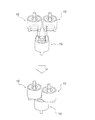
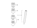
- FIG. 1 It is a perspective view which shows the small pipe type block which is an example of the toy block of the assembly toy which concerns on embodiment of this invention, and is a figure which shows a mode that two small pipe type blocks are combined.
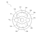
- FIG. 1 It is a top view which shows the detailed shape of the 1st plane of the small pipe type block shown in FIG.
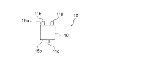
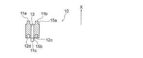
- FIG. 1 It is a front view of the small pipe type block shown in FIG.
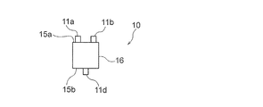
- FIG. is a rear view of the small pipe type block shown in FIG.
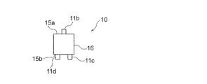
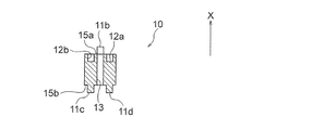
- FIG. 1 It is a right view of the small pipe type block shown in FIG.
- FIG. 3B is a cross-sectional view of the small pipe block shown in FIG. 1 along the line AA shown in FIG. 3E.
- FIG. 3B is a cross-sectional view of the small pipe block shown in FIG. 1 along the line BB shown in FIG. 3E.
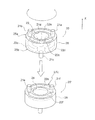
- It is a reference perspective view of the small pipe type block shown in FIG.
- It is a perspective view which shows the middle pipe type block which is an example of the toy block of the assembly toy concerning embodiment of this invention, and is a figure which shows a mode that two middle pipe type blocks are combined.
- It is a front view of the middle pipe type block shown in FIG.
- It is a rear view of the middle pipe type block shown in FIG.
- It is a left view of the middle pipe type block shown in FIG.
- FIG. 5B is a cross-sectional view of the middle pipe type block shown in FIG. 4 along the line AA shown in FIG. 5E.
- FIG. 5B is a cross-sectional view of the middle pipe type block shown in FIG. 4 along the line BB shown in FIG. 5E.
- It is a reference perspective view of the middle pipe type block shown in FIG. It is a perspective view which shows the large pipe type block which is an example of the toy block of the assembly toy which concerns on embodiment of this invention, and is a figure which shows a mode that two large pipe type blocks are combined.
- FIG. 7B is a cross-sectional view of the large pipe block shown in FIG. 6 along the line AA shown in FIG. 7E.
- FIG. 7B is a cross-sectional view of the large pipe block shown in FIG. 6 along the line BB shown in FIG. 7E.
- FIG. 7B is a cross-sectional view of the large pipe block shown in FIG.
- FIG. 7 is a reference perspective view of the large pipe type block shown in FIG. 6. It is a figure which shows a mode that three small pipe type blocks shown in FIG. It is a figure which shows a mode that the small pipe type block shown in FIG. 1 and the large pipe type block shown in FIG. 6 were combined. It is a perspective view which shows the middle reducer type
- FIG. 10B is a plan view of the medium reducer block shown in FIG. 10A.
- FIG. 10B is a bottom view of the middle reducer block shown in FIG. 10A.
- FIG. 11B is a plan view of the middle cap block shown in FIG. 11A.
- FIG. 11B is a bottom view of the middle cap block shown in FIG. 11A.
- FIG. 14A It is a perspective view which shows the small cheese type
- FIG. 16A It is a perspective view which shows the example of the combination at the time of couple
- FIG. 16B is a perspective view of the face portion of the bear doll shown in FIG. 16A.
- FIG. 16B is a side view of the face portion of the bear doll shown in FIG. 16A.
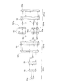
- FIG. 16B is an exploded view of the face portion of the bear doll shown in FIG. 16A.
- FIG. 16B shows the example which applied the use of the toy block of the assembled toy concerning embodiment of this invention as miscellaneous goods.
- It is a perspective view which shows the example of the aspect of the assembly of the toy block of the assembly toy which concerns on embodiment of this invention by displacement illustration.
- FIG. 20B is a side view showing another block to which the toy block according to the embodiment of the present invention is coupled in the assembly mode shown in FIG. 20A.
- FIG. 20A is a perspective view which shows the toy block of the assembly toy shown as another example of this invention, and is a figure which shows a mode that two toy blocks are couple
- FIG. 20A is a perspective view which shows the toy block of the assembly toy shown as another example of this invention, and is a figure which shows a mode that two toy blocks are couple
- a small pipe type block 10 as a toy block of an assembled toy will be described with reference to FIGS. 3A is symmetrical with the rear view of FIG. 3B, and the left side view of FIG. 3C is symmetric with the right side view of FIG. 3D.
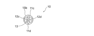
- a small pipe type block 10 as a first toy block has a cylindrical portion 16 having a substantially cylindrical shape. At both ends of the cylindrical portion 16, a circular first plane 15a and a second plane 15b are formed in parallel to each other.
- a through hole 13 is formed in the central portion of the first plane 15 a and extends in the axial direction of the small pipe block 10.
- male portions 11a and 11b which are a pair of cylindrical convex portions, protrude perpendicularly from the first plane 15a and extend at positions symmetrical with respect to the through hole 13.
- the protruding direction in which the male part protrudes perpendicularly to the first plane is defined as the X direction positive side
- the direction opposite to the X direction positive side is defined as the X direction negative side.
- a pair of female portions 12a and 12b are formed between the male portion 11a and the male portion 11b at symmetrical positions with the through hole 13 therebetween.
- the female portion 12a is a concave portion having a shape in which semicircular semicircular portions 122 and 123 are connected to both ends of a strip-shaped portion 121 that is an arc-shaped elongated strip shape, It is recessed from the first plane 15a vertically toward the X direction negative side.
- the female portion 12b is a concave portion having a shape in which the semicircular portions 125 and 126 are connected to both ends of the belt-like portion 124, which is an arc-shaped elongated belt shape, and is formed to be depressed on the negative side in the X direction.
- the pair of female portions 12a and 12b are formed as arc-shaped belt-like grooves on the first plane 15a.
- the length in the width direction of the female portions 12a and 12b is substantially the same as the diameter of the male portions 11a and 11b.
- the male portions 11a and 11b and the female portions 12a and 12b are provided so as to be arranged on the same circumference.
- the second plane 15b has the same shape as the first plane 15a. That is, a pair of male parts 11c, 11d and a pair of female parts 12c, 12d having the same shape as the male parts 11a, 11b and female parts 12a, 12b of the first plane 15a are also formed on the second plane 15b.
- the female portions 12c and 12d are formed so as to be vertically recessed from the second plane 15b on the X direction positive side opposite to the X direction negative side, which is the protruding direction of the male portions 11c and 11d.
- the male portions 11c and 11d and the female portions 12c and 12d are provided so as to be arranged on the same circumference. As shown in FIGS.
- the positions of the male portions 11a and 11b and the female portions 12a and 12b of the first plane 15a and the male portions 11c and 11d and the female portions 12c and 12d of the second plane 15b are as follows.
- the 90 ° phases are different from each other.
- the other small pipe type block 10 ′ to be coupled with the small pipe type block 10 includes a flat surface 15 c in which male parts 11 e and 11 f and female parts 12 e and 12 f are formed, as in the small pipe type block 10. . Therefore, when the small pipe type block 10 is coupled to another small pipe type block 10 ′, the male portions 11c and 11d of the second plane 15b of the small pipe type block 10 are respectively connected to the other small pipe type block 10 ′. Engage with the female portions 12e and 12f of the flat surface 15c.
- the length in the width direction of the female portions 12e and 12f of the plane 15c of the other small pipe type block 10 ′ is substantially the same as the diameter of the male portions 11c and 11d of the second plane 15b of the small pipe type block 10. is there. Therefore, the male parts 11c and 11d of the small pipe type block 10 are fitted so as not to easily come out unless the tensile force is intentionally applied to the female parts 12e and 12f of the other small pipe type blocks 10 ′. Combined and attached.
- the male portions 11c and 11d of the small pipe type block 10 are circular in the circumferential direction along the female portions 12e and 12f while being fitted to the female portions 12e and 12f of the other small pipe type blocks 10 ′. It can move in an arc.
- the male parts 11e and 11f of the plane 15c of the other small pipe type block 10 ′ are also connected to the second part of the small pipe type block 10 in the same manner as the engagement between the male parts 11c and 11d and the female parts 12e and 12f. It is engaged with the female portions 12c and 12d of the flat surface 15b.
- the length in the width direction of the female portions 12c and 12d of the second flat surface 15b of the small pipe type block 10 is also substantially the same as the diameter of the male portions 11e and 11f of the flat surface 15c of the other small pipe type block 10 ′.
- the male portions 11e and 11f of the other small pipe type block 10 ′ are circularly arranged in the circumferential direction along the female portions 12c and 12d while being fitted to the female portions 12c and 12d of the small pipe type block 10. It can move in an arc. Therefore, the small pipe type block 10 and the other small pipe type block 10 'can be rotated with each other as shown by the arrows in FIG. That is, the small pipe type block 10 can change a connection position suitably with respect to the plane 15c of other small pipe type blocks 10 '. In addition, when the small pipe type block 10 and other small pipe type block 10 'couple
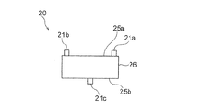
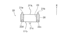
- the middle pipe type block 20 as a toy block of the assembled toy will be described.
- 5A is symmetrical with the rear view of FIG. 5B
- the left side view of FIG. 5C is symmetric with the right side view of FIG. 5D.
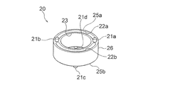
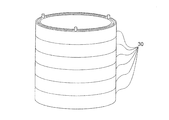
- the middle pipe type block 20 as the first toy block has a cylindrical portion 26 having a substantially cylindrical shape.
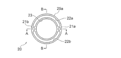
- a first plane 25a and a second plane 25b which are substantially annular planes, are formed in parallel to each other. That is, the outer peripheries of the first plane 25a and the second plane 25b are circular.
- mold block 20 is larger than the magnitude
- a circular opening 23 is formed in the central portion of the first plane 25a.
- male portions 21a and 21b which are a pair of cylindrical convex portions, protrude and extend in the X direction positive side at positions symmetrical to each other with the opening 23 therebetween.
- a pair of female portions 22a and 22b which are arc-shaped elongated strip-shaped recesses extending along the shape of the first flat surface 25a, are formed between the pair of male portions 21a and 21b. That is, the male parts 21a and 21b and the female parts 22a and 22b are provided so as to be arranged on the same circumference.
- female part 22a, 22b is extended toward the X direction negative side with respect to the 1st plane 25a, and is formed.
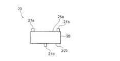
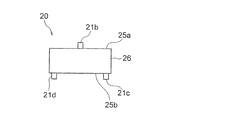
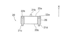
- the second plane 25b has the same shape as the first plane 25a.
- a pair of male parts 21c, 21d and a pair of female parts 22c, 22d having the same shape as the male parts 21a, 21b and female parts 22a, 22b of the first plane 25a are formed on the second plane 25b.
- the male parts 21c and 21d and the female parts 22c and 22d are also provided so as to be arranged on the same circumference.
- the positions of the male portions 21a, 21b and female portions 22a, 22b of the first plane 25a and the male portions 21c, 21d and female portions 22c, 22d of the second plane 25b are different from each other by 90 °.
- middle pipe type block 20 is detachably coupled to another middle pipe type block 20 'which is a second toy block having a similar structure.
- the other middle pipe type block 20 ′ to be coupled with the middle pipe type block 20 is provided with a flat surface 25 c on which male parts 21 e and 21 f and female parts 22 e and 22 f are formed, like the middle pipe type block 20. . Therefore, when the middle pipe type block 20 is joined to another middle pipe type block 20 ′, the male portions 21c and 21d of the second plane 25b of the middle pipe type block 20 are respectively the planes of the other middle pipe type block 20 ′. It is engaged with the female portions 22e and 22f of 25c.
- the male parts 21c and 21d of the middle pipe type block 20 do not apply a constant tensile force to the female parts 22e and 22f of the other middle pipe type blocks 20 ′. They are fitted so that they are not easily removed.
- the male parts 21c and 21d of the middle pipe type block 20 are arcuate along the extending direction of the female parts 22e and 22f while being fitted to the female parts 22e and 22f of the other middle pipe type block 20 ′. Can be moved to.
- the male parts 21e and 21f of the other middle pipe type block 20 ′ are also difficult to come out unless a certain pulling force is applied to the female parts 22c and 22d of the middle pipe type block 20, and along the female parts 22c and 22d. Can move in an arc shape in the circumferential direction. Accordingly, the middle pipe type block 20 and the other middle pipe type block 20 'can be rotated with each other while being connected after being joined. That is, the connecting position of the middle pipe type block 20 can be appropriately changed with respect to the plane 25c of the other middle pipe type block 20 '.
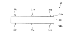
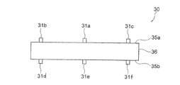
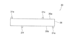
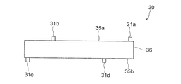
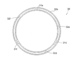
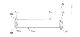
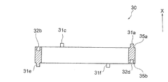
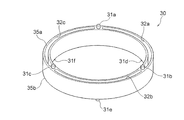
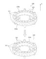
- the large pipe type block 30 which is the first toy block has an annular portion 36 having a substantially annular shape.
- a substantially annular first plane 35a and a second plane 35b are formed at both ends of the annular portion 36 in parallel with each other. That is, the outer peripheries of the first plane 35a and the second plane 35b are circular.
- the outer diameter of the first plane 35a or the second plane 35b of the large pipe block 30 is larger than the outer diameter of the first plane 25a or the second plane 25b of the middle pipe block 20.
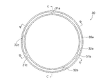
- the male portions 31a, 31b, and 31c which are three cylindrical convex portions, are provided 120 degrees apart from each other and extend so as to protrude to the positive side in the X direction. Further, between the male portions 31a, 31b, and 31c, three female portions 32a, 32b, and 33c, which are concave portions having an arcuate elongated strip shape, are formed. As shown in FIGS. 7G to 7I, the female portions 32a, 32b, and 33c are formed to be depressed toward the negative side in the X direction with respect to the first plane 25a.
- the second plane 35b has the same shape as the first plane 35a.
- three male parts 31d, 31e, 31f and three females having the same shape as the male parts 31a, 31b, 31c and the female parts 32a, 32b, 32c of the first plane 35a are provided on the second plane 35b.
- Portions 32d, 32e, and 32f are formed. That is, the male portions 31d, 31e, 31f and the female portions 32d, 32e, 32f are also provided so as to be arranged on the same circumference.
- the positions of the male portions 31a, 31b, 31c and the female portions 32a, 32b, 32c of the first plane 35a and the male portions 31d, 31e, 31f and the female portions 32d, 32e, 32f of the second plane 35b are 180 mutually. ° The phase is different.
- the other large pipe type block 30 ′ coupled to the large pipe type block 30 is similar to the large pipe type block 30 in that a plane 35 c on which male parts 31 g, 31 h, 31 i and female parts 32 g, 32 h, 32 i are formed. It has. Accordingly, when the large pipe type block 30 is coupled to another large pipe type block 30 ′, the male portions 31d, 31e, 31f of the second plane 35b of the large pipe type block 30 are respectively connected to the other large pipe type block 30 ′.
- the male parts 31d, 31e, 31f of the large pipe type block 30 are replaced with the female parts 32g, 32h, 32i of the other large pipe type block 30 ′.
- the male portions 31d, 31e, 31f of the large pipe type block 30 follow the female portions 32g, 32h, 32i while being fitted to the female portions 32g, 32h, 32i of the other large pipe type blocks 30 ′. Can move in an arc shape in the circumferential direction.
- the male portions 31g, 31h, 31i of the plane 35c of the other large pipe type block 30 ' are fitted into the female portions 32d, 32e, 32f of the second plane 35b of the large pipe type block 30, respectively.
- the male parts 31g, 31h, 31i of the other large pipe type block 30 ′ are also difficult to be removed from the female parts 32d, 32e, 32f of the large pipe type block 30, and are circumferential along the female parts 32d, 32e, 32f. Can be moved in an arc. Accordingly, the large pipe block 30 and the other large pipe block 30 'can be rotated together while being connected after being joined. That is, the connecting position of the large pipe type block 30 can be appropriately changed with respect to the plane 35c of the other large pipe type block 30 '.
- the method of connecting the small pipe type block 10, the medium pipe type block 20, and the large pipe type block 30 is not limited to the above-described method of connecting toy blocks of the same type one by one. That is, as shown in FIG. 8, the center positions of the three small pipe-type blocks 10 are shifted, and the male part and the female part are engaged with each other. These two small pipe-type blocks 10 can be combined. Further, as shown in FIG. 9, the small pipe type block 10 can be coupled to one plane of the large pipe type block 30. 8 and FIG. 9, the small pipe type block 10 and the middle pipe type block 20 may be connected, and the middle pipe type block 20 and the large pipe type block 30 may be connected. It may be connected.
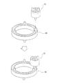
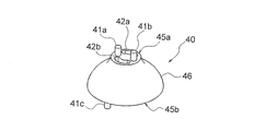
- the medium reducer type block 40 has a small-diameter flat surface 45a whose outer periphery is circular at one end, and a large-diameter flat surface 45b whose outer diameter is larger than the small-diameter flat surface 45a and has a circular outer periphery at the other end.
- the small-diameter flat surface 45a has the same structure as the first flat surface 15a or the second flat surface 15b of the small pipe-type block 10, and male portions 41a and 41b that are a pair of substantially cylindrical convex portions.
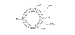
- the large-diameter plane 45b has a substantially annular shape having a structure similar to that of the first plane 25a or the second plane 25b of the middle pipe-type block 20, and has a pair of cylindrical projections.
- the male parts 41c and 41d extend so as to protrude perpendicularly to the large-diameter plane 45b
- the female parts 42c and 42d are perpendicular to the protruding direction of the male parts 41c and 41d with respect to the large-diameter plane 45b. It is formed in a hollow.
- the side surface 46 of the middle reducer block 40 has a smooth substantially dome shape extending from the small-diameter plane 45a toward the large-diameter plane 45b.
- the small pipe type block 10 can be connected to the small diameter plane 45a of the medium reducer type block 40, and the medium pipe type block 20 can be connected to the large diameter plane 45b. That is, the small pipe type block 10 and the medium pipe type block 20 having different diameters are smoothly connected via the medium reducer type block 40.
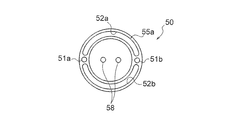
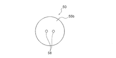
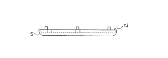
- the middle cap type block 50 as a toy block will be described with reference to FIGS. 11A to 11C.
- the middle cap type block 50 has an annular flat surface 55a at one end and a circular flat surface 55b at the other end.
- the annular plane 55a has the same structure as the first plane 25a or the second plane 25b of the middle pipe-type block 20, and has a pair of male convex portions 51a and 51b that are cylindrical projections and a pair of arc-shaped strips. It has female parts 52a and 52b which are recessed parts.
- the male parts 51a and 51b extend perpendicularly to the annular plane 55a, and the female parts 52a and 52b are perpendicular to the direction opposite to the protruding direction of the male parts 51a and 51b with respect to the annular plane 55a.
- a depression is formed.
- two holes 58 are formed in the center portion of the middle cap type block 50.
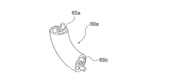
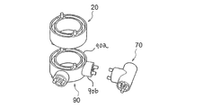
- the small elbow-type (90-degree) block 60a in FIG. 12A has a tube shape curved by 90 degrees, and a male portion having a structure similar to that of the first flat surface 15a or the second flat surface 15b of the small pipe-type block 10 is provided at both ends.
- the planes 65a and 65b which have a female part are formed. That is, the planes 65a and 65b are arranged in different directions that form 90 degrees with each other. Further, the small elbow type (45 degrees) block 60b shown in FIG.
- the 12B is shorter in length than the small elbow type (90 degrees) block 60a and has a tube shape curved by 45 degrees.
- planes 65c and 65d having male and female parts having the same structure as the first plane 15a or the second plane 15b of the small pipe type block 10 are formed. . That is, the plane 65c and the plane 65d are arranged so as to extend in different directions at 45 degrees.
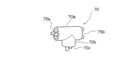
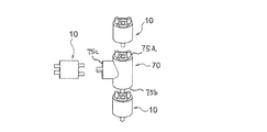
- the toy block shown in FIG. 13A is a small cheese block 70, in which a cylindrical portion 70a and another cylindrical portion 70b are combined at a right angle, and a part of the cylindrical portion 70b is embedded in the center of the cylindrical portion 70a.
- a first plane 75a and a second plane 75b arranged in parallel with each other are formed at both ends of the cylindrical portion 70a.
- a third plane 75c is formed at the end of the cylindrical portion 70b. That is, the first plane 75a or the second plane 75b and the third plane 75c are arranged in different directions that form 90 degrees with each other.
- the first plane 75a, the second plane 75b, and the third plane 75c have a male part and a female part having the same structure as the first plane 15a or the second plane 15b of the small pipe-type block 10.
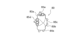
- the toy block shown in FIG. 13B is a small cross type (180 degrees) block 80, and a cylindrical portion 80a and another cylindrical portion 80b are combined at right angles with each other at a central portion to form a cross shape.
- Flat surfaces 85a and 85b are formed at both ends of the cylindrical portion 80a, and flat surfaces 85c and 85d are formed at both ends of the cylindrical portion 80b. That is, the planes 85a and 85b of the cylindrical portion 80a and the planes 85c and 85d of the cylindrical portion 80b are arranged in different directions that form 90 degrees with each other.
- the planes 85 a, 85 b, 85 c, 85 d of the small cross type (180 degrees) block 80 have male and female parts having the same structure as the first plane 15 a or the second plane 15 b of the small pipe type block 10. is doing.
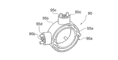
- the toy block shown in FIG. 13C is a medium cross type (90 degrees) block 90, and two toy blocks are spaced 90 degrees from each other on the outer peripheral surface of the annular portion 90a having the same structure as the middle pipe type block 20.
- Cylindrical portions 90b and 90c are provided.
- planes 95a and 95b having a male part and a female part having the same structure as the first plane 25a or 25b of the middle pipe block 20 are formed.
- flat surfaces 95c and 95d having male and female portions having the same structure as the first flat surface 15a or 15b of the small pipe-type block 10 are formed at the respective end portions of the cylindrical portions 90b and 90c. That is, the plane 95a, the plane 95b, and the planes 95c and 95d are arranged in different directions that form 90 degrees with each other.
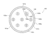
- the large cap type (subspecies) block 100 is a substantially dish-shaped toy block, and has an annular plane 105a on one surface and a bottom plane 105b surrounded by the annular plane 105a.
- the opposite surface of the bottom flat surface 105 b is the lid surface 107.
- the annular plane 105a has the same shape as the first plane 35a or the second plane 35b of the large pipe block 30, and has three male parts 101a, 101b, 101c and female parts 102a, 102b, 102c having the same structure. have. That is, the male parts 101a, 101b, and 101c extend perpendicularly to the annular plane 105a, and the female parts 102a, 102b, and 102c are the protruding directions of the male parts 101a, 101b, and 101c with respect to the annular plane 105a. It is formed to be recessed vertically in the opposite direction.
- the male portions 101a, 101b, and 101c and the female portions 102a, 102b, and 102c are provided on the same circumference.
- attachment portions 106 each having a pair of male portions 106a, a pair of female portions 106b, and attachment holes 106c are formed as one unit.
- the pair of male portions 106a and the pair of female portions 106b of the attachment portion 106 are the same as the male portions 11a to 11d and the female portions 12a to 12d of the first flat surface 15a or the second flat surface 15b of the small pipe block 10, respectively.
- the shape is the shape.
- the pair of male portions 106a extends so as to protrude perpendicular to the bottom plane 105b, and the pair of female portions 106b are formed to be recessed perpendicularly to the bottom plane 105b in a direction opposite to the extending direction of the male portion 106a.
- the pair of male portions 106a and the pair of female portions 106b of each attachment portion 106 are provided on the same circumference.
- FIG. 15A the middle pipe type block 20, the middle reducer type block 40, the two small pipe type blocks 10, the small elbow type (90 degrees) block 60a, and the small elbow type (45 degrees) block are arranged in order from the top. 60b is coupled.
- the two small pipe-type blocks 10 are coupled with each other even at the center position.
- FIG. 15B is an example in which the small pipe type block 10 is coupled to each of the three flat surfaces 75 a, 75 b, 75 c of the small cheese type block 70.
- FIG. 15C is an example in which the middle pipe type block 20 is coupled to the annular portion 90a of the middle cross type (90 degrees) block 90 and the small cheese type block 70 is coupled to the cylindrical portion 90b.
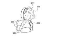
- a bear doll 200 as shown in FIG. 16A can be made by combining various toy blocks.
- the doll 200 includes a face part 201, a body 202 connected to the face part 201, and four legs 203 attached to the body 202.
- a pair of ears 201 a is attached to the face 201.
- the ear 201 a of the doll 200 can be moved with respect to the face 201.
- the angle and direction can change the face part 201 and the leg 203 of the doll 200.
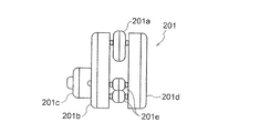
- the face 201 of the bear doll 200 has an ear 201a, a substantially columnar face front portion 201b attached to the front side with the ear 201a interposed therebetween, and a substantially columnar shape attached to the rear side with the ear 201a interposed therebetween.
- Face rear part 201d Face rear part 201d.
- the face part 201 includes a nose 201c attached to the lower half of the front face part 201b, and a spacer 201e provided between the front face part 201b and the rear face part 201d.
- the ear 201a is obtained by connecting two middle cap-type blocks 50. Further, the front face part 201b and the rear face part 201d are obtained by connecting a large cap type block 50b having a diameter larger than that of the middle cap type block 50 to the large pipe type block 30, respectively. Further, the pin 2 representing the bear's eye is inserted into the connecting hole of the large cap type block 50b of the front face portion 201b.
- the nose 201 c is a combination of the middle pipe type block 20, the middle cap type block 50, and a small cap type block 50 a having a smaller diameter than the middle cap type block 50.
- Each spacer 201e is a combination of two small cap-type blocks 50a. Ears 201a and spacers 201e between the front face part 201b and the rear face part 201d are respectively attached to the front and rear large pipe type blocks 30 by pins 3.
- a mechanical pencil structure can be formed by connecting a plurality of small pipe-type blocks 10.
- large pipe-type blocks 30 can be stacked to make miscellaneous goods such as small items.
- the small pipe type block 10 can be freely fitted by fitting the male part of the small pipe type block 10 into the rail-like grooves 4a or 4b formed in the plate-like block 4 and orthogonal to each other. It is also possible to create a dynamic structure that moves in a straight line. Further, as shown in FIGS. 20A and 20B, the male part of the small pipe-type block 10 is placed in the three pairs of rail-shaped grooves 5a, 5b, 5c formed on the annular edge 5d of the dish-shaped block 5. The small pipe type block 10 can be moved in an arc shape by fitting.
- the male part and the female part formed on the plane of the toy block are provided on the same circumference, the male part and the female part are arranged linearly. Compared with the case where it connects, the plane as a connection surface of a toy block can be connected at various angles. Therefore, the freedom of modeling by combining toy blocks is increased.
- each toy block is rotated.
- the position of the toy blocks could not be shifted.
- one toy block can rotate with respect to the other toy block while maintaining the state where the toy blocks are connected to each other. Therefore, even after assembling a plurality of toy blocks into a certain shape, the shape of the details can be changed as appropriate, and the degree of freedom of modeling becomes higher.
- the toy block can be moved not only in rotation but also in linear movement or arcuate movement along rail-like grooves of other members as shown in FIGS. 19 and 20A. It is possible to form a dynamic structure on the assumption that it can be moved easily.
- each toy block has a male part and a female part on one plane, so that the user does not mind the direction of the toy block from any plane.
- Other toy blocks can be connected. Therefore, the connection member for connecting toy blocks becomes unnecessary, and the number of parts as the whole assembly toy can be reduced.
- the male part of various toy blocks is a cylindrical convex part
- the female part is a concave part formed in a strip shape
- the male part is a female part relative to the female part. Since they can be fitted in the width direction, the toy blocks are difficult to remove from each other unless a certain tensile force is applied.
- the female portion is an arc-shaped concave portion, the male portion and the female portion of the toy blocks can be fitted to each other and smoothly rotated, and the shape can be formed after the user assembles the toy blocks. Twist to make it possible.
- the medium reducer type block 40 shown in FIG. 10A and the middle cross type (90 degree) block shown in FIG. 13C have two or more circular planes with different outer diameters, thereby connecting toy blocks having different diameters to each other. Can be made. Further, since the side surface 46 of the middle reducer type block 40 is a smooth curved surface, toy blocks having different diameters can be smoothly connected to each other via the middle reducer type block 40.
- various toy blocks have a pair of planes arranged in parallel to each other, a plurality of toy blocks can be connected in a straight line.
- the small elbow type (90 degrees) block 60a shown in FIG. 12A, the small elbow type (45 degrees) 60b shown in FIG. 12B, the small cheese mold block 70 shown in FIG. 13A, and the small cross type (180 degrees) shown in FIG. Block 80 or medium cross (90 degree) block 90 shown in FIG. 13C has two or more planes arranged in different directions. Thereby, a toy block can be connected in various directions and more three-dimensional modeling is attained.
- the male portion of the toy block is a cylindrical convex portion, but it may be a prismatic shape or other column shape.
- the plane formed on the toy block is not limited to a circle, and may be an ellipse.
- an optical fiber may be provided in a through hole or an opening formed in each toy block.
- an optical fiber can be light-emitted and the structure shaped by the some toy block can be made to shine.
- the shape of the female portion formed in the toy block of the assembled toy according to the present invention is not limited to the elongated belt-shaped groove, and may be a recess having a circular cross section as shown in FIG. 21 or FIG. Good.
- the toy block 230 shown in FIG. 21 will be described.
- a substantially annular first plane 235a and a second plane 235b are formed in parallel to each other at both ends of the substantially cylindrical toy block 230. That is, the outer circumferences of the first plane 235a and the second plane 235b are circular.
- male portions 231 that are five columnar convex portions are provided at equal intervals along the shape of the first plane 235a, and protrude to the positive side in the X direction. It extends.
- three female portions 232 each having a circular cross section are formed between the male portions 231 so as to be depressed toward the negative side in the X direction. That is, on the first plane 235a, the arrangement of one male part 231 and three female parts 232 is repeated five times along the circumferential direction of the first plane 235a. Accordingly, a total of 15 recesses are provided in the first plane 235a.
- the five male parts 231 and the fifteen female parts 232 are provided so as to be arranged on the same circumference.
- the second plane 235b has the same shape as the first plane 235a, and has five male parts 231 and 15 female parts 232.
- the toy block 230 which is the first toy block, can be combined with another toy block 230 ', which is the second toy block having the same structure.
- the male part 231 of the second plane 235b of the first toy block 230 is detachably fitted to the female part 232 of the plane 235c of the second toy block 230 ′.
- the male part 231 of the plane 235c of the second toy block 230 ' is detachably fitted to the female part 232 of the second plane 235b of the first toy block 230'.
- the first toy block 230 can be compared with the second toy block 230 ′. They may be combined at such an angle.
- a substantially annular first plane 335a and a second plane 335b are formed in parallel with each other at both ends of the substantially cylindrical toy block 330, respectively. That is, the outer peripheries of the first plane 335a and the second plane 335b are circular.
- ten male portions 331 that are ten columnar convex portions and ten female portions 332 that are concave portions having a circular cross section follow the shape of the first plane 335a. They are arranged alternately.
- the male part 331 protrudes and extends to the X direction positive side
- the female part 332 is formed to be depressed toward the X direction negative side.
- the second plane 335b has the same shape as the first plane 335a, and has ten male parts 331 and ten female parts 332.
- the toy block 330 which is the first toy block, can be combined with the toy block 330 ', which is the second toy block having the same structure.
- the male part 331 of the second plane 335b of the first toy block 330 is detachably fitted to the female part 332 of the plane 335c of the second toy block 330 ′.
- the male part 331 of the plane 335c of the second toy block 330 ' is detachably fitted to the female part 332 of the second plane 335b of the first toy block 330'.
- the first toy block 330 is a plane of the second toy block 330 ′. It may be coupled at any angle to 335c.
- the male part and the female part are provided on the same circumference, so that the planes of the toy block are connected at various angles. be able to. Moreover, since toy blocks are connected so that attachment or detachment is possible, the toy blocks once combined can be removed, and the connection position can be changed by changing the angle and reconnecting them again.
- the arrangement of one male part 231 and three female parts 232 larger than the male part 231 is repeated five times on the first plane 235a or the second plane 235b. Is arranged. For this reason, the first toy block 330 can be coupled to the second toy block 330 ′ at various angles while changing the angle in small increments.
- sequence of the male part 231 and the female part 232 provided in the 1st plane 235a or the 2nd plane 235b of the toy block 230 is the arrangement
- the first plane 235a or the second plane 235b of the toy block 230 is provided with a repeated arrangement composed of two or more male parts and a plurality of female parts greater than the male parts. May be. Also, in the toy block 330 shown in FIG. 22, since the male part 331 and the female part 332 are alternately arranged on the same circumference, the angle is adjusted in small increments between the toy blocks 330 like the toy block 230. However, it can be connected at various angles.
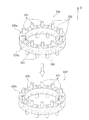
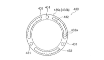
- the shape of the female part formed in the toy block of the assembled toy according to the present invention is, as shown in FIGS. 23A and 23B, a concave part having a belt shape in which a plurality of circles having the same diameter overlap and are continuous on the circumference. It may be.
- a substantially annular first plane 435a and a second plane 435b as shown in FIG. 23A are formed in parallel to each other at both ends of the substantially cylindrical toy block 430, respectively. Has been. That is, the outer circumferences of the first plane 435a and the second plane 435b are circular.
- male portions 431 which are three cylindrical convex portions, are provided 120 degrees apart from each other along the shape of the first plane 435a, and protrude to the positive side in the X direction. It extends.
- a female portion 432 that is a band-shaped recess is formed between each of the three male portions 431.
- Each female portion 432 is a concave portion having a band shape in which twelve circles 432a having the same diameter overlap to be continuous on the circumference, and is formed to be depressed toward the negative side in the X direction.
- Each circle 432a is formed so that the male part 431 can be detachably fitted.
- the second plane 435b has the same shape as the first plane 435a and includes three male parts 431 and three female parts 432.
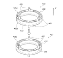
- the toy block 430 as the first toy block can be combined with another toy block 430 'as the second toy block having the same structure.
- the male part 431 of the second plane 435b of the first toy block 430 is detachably fitted to the female part 432 of the plane 435c of the second toy block 430 ′.
- the male part 431 of the plane 435c of the second toy block 430 ' is detachably fitted to the female part 432 of the second plane 435b of the first toy block 430.
- the male part 431 is fitted at a position corresponding to each of the circles 432a, and the position is fixed.
- each male portion 431 It can move along the extending direction of the female part 432 while being fitted to the female part 432. That is, the male part 431 fitted in a position corresponding to the circle 432a of the female part 432 moves to a position corresponding to another adjacent circle 432a by applying a force of a predetermined level or more in the extending direction of the female part 432. can do.
- the male part 431 and the female part 432 are provided on the same circumference, so that the second plane 435b of the first toy block 430 is used as the second toy block. It can be connected at various angles to the plane 435c of 430 '. Further, the male part 431 of the toy block 430 can move in the extending direction of the female part 432 while being fitted to the female part 432. Therefore, the 1st toy block 430 can rotate with respect to 2nd toy block 430 ', maintaining the state connected with 2nd toy block 430', and can change a connection position.
- the male part 431 is fixed at a position corresponding to the circle 432a of the female part 432 unless a certain force is applied to the toy block 430, the first toy block 430 and the second toy block 430 ' Can be bonded to each other in a stable state.
Landscapes
- Toys (AREA)
Abstract
In the present invention, a toy block for an assembly toy has a first flat surface and a second flat surface at both ends. Formed on the first flat surface are male parts that project vertically and female parts that are vertically indented. Formed on the second flat surface are a male part that vertically projects, and female parts that are vertically indented. When two toy blocks are linked together, the male parts of one block fit into the female parts of other toy block, and the male part of the other toy block fits into a female part of the other toy block. This allows the linking surfaces of the toy blocks having the male parts and female parts to link to each other at a variety of angles. The toy blocks rotate relative to each other when linked together.
Description
この発明は、組立玩具に関する。
This invention relates to an assembled toy.
従来、複数のブロックを連結させることにより、種々の形状を作り上げて遊ぶ組立玩具がある。例えば、特許文献1には、六面に凹凸を有する略立方形状の複数のブロックの凹部と凸部とを互い違いに係合させ、三次元的に種々な形を造形するブロック組立玩具が記載されている。ここで、ブロックの六面の各々に形成される凸部及び凹部は、ブロック同士を連結させるための雄部及び雌部として構成される。
Conventionally, there are assembled toys that are played by creating various shapes by connecting a plurality of blocks. For example, Patent Document 1 describes a block assembly toy that three-dimensionally forms various shapes by alternately engaging concave portions and convex portions of a plurality of substantially cubic blocks having irregularities on six surfaces. ing. Here, the convex portion and the concave portion formed on each of the six surfaces of the block are configured as a male portion and a female portion for connecting the blocks to each other.
しかしながら、特許文献1のブロック組立玩具では、ブロック同士を連結させる際、ブロックの面に形成される凹凸に対して別のブロックの面を決まった角度でしか組み合わせることができない。すなわち、様々な角度をつけてブロック同士を連結させることはできない。そのため、ブロックを組み合わせることによる造形の自由度が制限される。
However, in the block assembly toy of Patent Document 1, when connecting the blocks, the surface of another block can be combined only at a fixed angle with respect to the irregularities formed on the surface of the block. That is, the blocks cannot be connected with various angles. Therefore, the freedom of modeling by combining blocks is limited.
この発明は、このような問題を解決するためになされ、少なくとも一面に雄部及び雌部を有する複数の玩具ブロックの連結面同士を様々な角度で連結することができる組立玩具を提供することを目的とする。
This invention is made in order to solve such a problem, and provides the assembly toy which can connect the connection surfaces of the some toy block which has a male part and a female part on at least one surface at various angles. Objective.
上記の課題を解決するために、この発明に係る組立玩具は、互いに連結され得る第一の玩具ブロック及び第二の玩具ブロックを有し、玩具ブロックの各々は、少なくとも1つの平面と、平面から垂直に突出して延びる雄部と、平面から雄部の突出方向と反対の方向に垂直に窪んで形成される雌部とを備え、雄部及び雌部は平面上において同一の円周上に設けられ、第一の玩具ブロックの雄部が第二の玩具ブロックの雌部に着脱可能に嵌合するとともに、第二の玩具ブロックの雄部が第一の玩具ブロックの雌部に着脱可能に嵌合することにより、第一玩具ブロックと第二の玩具ブロックとは連結可能であるとともに、第一の玩具ブロックは第二の玩具ブロックに対して連結位置を変更可能である。
In order to solve the above-described problems, an assembled toy according to the present invention includes a first toy block and a second toy block that can be coupled to each other, and each of the toy blocks includes at least one plane and a plane. A male part extending vertically and a female part vertically recessed in a direction opposite to the protruding direction of the male part from the plane, the male part and the female part being provided on the same circumference on the plane The male part of the first toy block is detachably fitted to the female part of the second toy block, and the male part of the second toy block is detachably fitted to the female part of the first toy block. By combining, the first toy block and the second toy block can be coupled, and the first toy block can change the coupling position with respect to the second toy block.
また、この発明に係る組立玩具において、第一の玩具ブロックと第二の玩具ブロックとが互いに連結した状態を保持しながら、第一の玩具ブロックは第二の玩具ブロックに対して移動可能であってもよい。
In the assembled toy according to the present invention, the first toy block is movable with respect to the second toy block while maintaining the state in which the first toy block and the second toy block are connected to each other. May be.
また、この発明に係る組立玩具の玩具ブロックの雄部は平面から突出する柱形状の凸部を有し、雌部は平面上に円弧状の帯状に形成される凹部を有し、雄部の凸部は雌部の凹部に対して凹部の幅方向において嵌合可能であり、第一の玩具ブロックと第二の玩具ブロックとが互いに連結した状態を保持しながら、第一の玩具ブロック及び第二の玩具ブロックの各々の雄部の凸部が各々の雌部の凹部に沿って移動することにより、第一の玩具ブロックは第二の玩具ブロックに対して回転してもよい。
Further, the male part of the toy block of the assembled toy according to the present invention has a columnar convex part protruding from the plane, the female part has a concave part formed in an arcuate belt shape on the plane, The convex portion can be fitted to the concave portion of the female portion in the width direction of the concave portion, and the first toy block and the second toy block are held while the first toy block and the second toy block are connected to each other. The first toy block may rotate with respect to the second toy block by moving the convex part of each male part of the second toy block along the concave part of each female part.
また、雄部と雌部とは同一の円周上において交互に配置されてもよい。
またさらに、雄部と雌部とは同一の円周上において、少なくとも1つの雄部と、雄部よりも多い複数の雌部との配列を繰り返して配置されていてもよい。 Moreover, the male part and the female part may be alternately arranged on the same circumference.
Furthermore, the male part and the female part may be arranged by repeatedly arranging at least one male part and a plurality of female parts larger than the male part on the same circumference.
この発明に係る組立玩具によれば、少なくとも一面に雄部及び雌部を有する複数の玩具ブロックの連結面同士を様々な角度で連結することができる。
According to the assembled toy according to the present invention, the connecting surfaces of a plurality of toy blocks having a male part and a female part on at least one surface can be connected at various angles.
以下、この発明の実施の形態について添付図面に基づいて説明する。なお、この発明において組立玩具とは、以下に説明する各種の玩具ブロックの各々を着脱可能に組み合わせて、種々の形状の構造物を造形するおもちゃである。
まず、図1,2及び図3A~3Iに基づいて、組立玩具の玩具ブロックとしての小パイプ型ブロック10について説明する。なお、図3Aの正面図は図3Bの背面図と対称であり、図3Cの左側面図は図3Dの右側面図と対称である。
図1を参照すると、第一の玩具ブロックである小パイプ型ブロック10は略円筒形状の円筒部分16を有する。円筒部分16の両端には、円形の第一平面15a及び第二平面15bが互いに平行に形成されている。ここで、第一平面15aの中央部分には、貫通孔13が形成され、小パイプ型ブロック10の軸方向に延びている。第一平面15a上では、貫通孔13を挟んで対称となる位置に一対の円柱形状の凸部である雄部11a,11bが第一平面15aから垂直に突出して延びている。
なお、以下の説明において雄部が第一平面に対して垂直に突出する突出方向をX方向正側とし、X方向正側の反対の方向をX方向負側とする。 Embodiments of the present invention will be described below with reference to the accompanying drawings. In the present invention, the assembled toy is a toy that forms various types of structures by detachably combining various toy blocks described below.
First, a smallpipe type block 10 as a toy block of an assembled toy will be described with reference to FIGS. 3A is symmetrical with the rear view of FIG. 3B, and the left side view of FIG. 3C is symmetric with the right side view of FIG. 3D.
Referring to FIG. 1, a smallpipe type block 10 as a first toy block has a cylindrical portion 16 having a substantially cylindrical shape. At both ends of the cylindrical portion 16, a circular first plane 15a and a second plane 15b are formed in parallel to each other. Here, a through hole 13 is formed in the central portion of the first plane 15 a and extends in the axial direction of the small pipe block 10. On the first plane 15a, male portions 11a and 11b, which are a pair of cylindrical convex portions, protrude perpendicularly from the first plane 15a and extend at positions symmetrical with respect to the through hole 13.
In the following description, the protruding direction in which the male part protrudes perpendicularly to the first plane is defined as the X direction positive side, and the direction opposite to the X direction positive side is defined as the X direction negative side.
まず、図1,2及び図3A~3Iに基づいて、組立玩具の玩具ブロックとしての小パイプ型ブロック10について説明する。なお、図3Aの正面図は図3Bの背面図と対称であり、図3Cの左側面図は図3Dの右側面図と対称である。
図1を参照すると、第一の玩具ブロックである小パイプ型ブロック10は略円筒形状の円筒部分16を有する。円筒部分16の両端には、円形の第一平面15a及び第二平面15bが互いに平行に形成されている。ここで、第一平面15aの中央部分には、貫通孔13が形成され、小パイプ型ブロック10の軸方向に延びている。第一平面15a上では、貫通孔13を挟んで対称となる位置に一対の円柱形状の凸部である雄部11a,11bが第一平面15aから垂直に突出して延びている。
なお、以下の説明において雄部が第一平面に対して垂直に突出する突出方向をX方向正側とし、X方向正側の反対の方向をX方向負側とする。 Embodiments of the present invention will be described below with reference to the accompanying drawings. In the present invention, the assembled toy is a toy that forms various types of structures by detachably combining various toy blocks described below.
First, a small
Referring to FIG. 1, a small
In the following description, the protruding direction in which the male part protrudes perpendicularly to the first plane is defined as the X direction positive side, and the direction opposite to the X direction positive side is defined as the X direction negative side.
そして、雄部11aと雄部11bとの間には、一対の雌部12a,12bが、貫通孔13を挟んで対称となる位置に形成される。図2に示すように、雌部12aは、円弧状の細長帯形状である帯状部121の両端の各々に略半円形状の半円部122,123が接続された形状をなす凹部であり、第一平面15aから垂直にX方向負側に向かって窪んで形成されている。また同様に、雌部12bは、円弧状の細長帯形状である帯状部124の両端の各々に半円部125,126が接続された形状をなす凹部であり、X方向負側に窪んで形成されている。すなわち、一対の雌部12a,12bは、第一平面15a上に、円弧形状の帯状の溝として形成されている。なお、雌部12a,12bの幅方向の長さは雄部11a,11bの直径とほぼ同一である。また、雄部11a,11bと雌部12a,12bとは同一の円周上に配列されるように設けられている。
A pair of female portions 12a and 12b are formed between the male portion 11a and the male portion 11b at symmetrical positions with the through hole 13 therebetween. As shown in FIG. 2, the female portion 12a is a concave portion having a shape in which semicircular semicircular portions 122 and 123 are connected to both ends of a strip-shaped portion 121 that is an arc-shaped elongated strip shape, It is recessed from the first plane 15a vertically toward the X direction negative side. Similarly, the female portion 12b is a concave portion having a shape in which the semicircular portions 125 and 126 are connected to both ends of the belt-like portion 124, which is an arc-shaped elongated belt shape, and is formed to be depressed on the negative side in the X direction. Has been. That is, the pair of female portions 12a and 12b are formed as arc-shaped belt-like grooves on the first plane 15a. The length in the width direction of the female portions 12a and 12b is substantially the same as the diameter of the male portions 11a and 11b. The male portions 11a and 11b and the female portions 12a and 12b are provided so as to be arranged on the same circumference.
また、第二平面15bは第一平面15aと同様の形状を有している。すなわち、第二平面15bにも、第一平面15aの雄部11a,11b及び雌部12a,12bと同様の形状の一対の雄部11c,11d及び一対の雌部12c,12dが形成される。ここで、雌部12c,12dは、第二平面15bから、雄部11c,11dの突出方向であるX方向負側とは反対の方向のX方向正側に垂直に窪んで形成されている。また、雄部11c,11dと雌部12c,12dとは同一の円周上に配列されるように設けられる。なお、図3E及び図3Fに示すように、第一平面15aの雄部11a,11b及び雌部12a,12bと第二平面15bの雄部11c,11d及び雌部12c,12dとの位置は、互いに90°位相が異なっている。
The second plane 15b has the same shape as the first plane 15a. That is, a pair of male parts 11c, 11d and a pair of female parts 12c, 12d having the same shape as the male parts 11a, 11b and female parts 12a, 12b of the first plane 15a are also formed on the second plane 15b. Here, the female portions 12c and 12d are formed so as to be vertically recessed from the second plane 15b on the X direction positive side opposite to the X direction negative side, which is the protruding direction of the male portions 11c and 11d. The male portions 11c and 11d and the female portions 12c and 12d are provided so as to be arranged on the same circumference. As shown in FIGS. 3E and 3F, the positions of the male portions 11a and 11b and the female portions 12a and 12b of the first plane 15a and the male portions 11c and 11d and the female portions 12c and 12d of the second plane 15b are as follows. The 90 ° phases are different from each other.
次に、図1のように小パイプ型ブロック10を、同様の構造を有する第二の玩具ブロックである他の小パイプ型ブロック10’と結合させる際の結合の方法について説明する。
なお、小パイプ型ブロック10と結合させる他の小パイプ型ブロック10’は、小パイプ型ブロック10と同様に、雄部11e,11f及び雌部12e,12fが形成された平面15cを備えている。従って、小パイプ型ブロック10を他の小パイプ型ブロック10’と結合させる際は、小パイプ型ブロック10の第二平面15bの雄部11c,11dをそれぞれ、他の小パイプ型ブロック10’の平面15cの雌部12e,12fに係合させる。ここで、他の小パイプ型ブロック10’の平面15cの雌部12e,12fの幅方向の長さは、小パイプ型ブロック10の第二平面15bの雄部11c,11dの直径とほぼ同一である。そのため、小パイプ型ブロック10の雄部11c,11dは、他の小パイプ型ブロック10’の雌部12e,12fに対して、意図的に引っ張り力を加えない限りは容易に抜けないように嵌合されて取り付けられている。一方、小パイプ型ブロック10の雄部11c,11dは、他の小パイプ型ブロック10’の雌部12e,12fに嵌合された状態のまま雌部12e,12fに沿って円周方向に円弧状に移動することができる。 Next, a method of coupling when the smallpipe type block 10 is combined with another small pipe type block 10 ′ which is a second toy block having the same structure as shown in FIG. 1 will be described.
The other smallpipe type block 10 ′ to be coupled with the small pipe type block 10 includes a flat surface 15 c in which male parts 11 e and 11 f and female parts 12 e and 12 f are formed, as in the small pipe type block 10. . Therefore, when the small pipe type block 10 is coupled to another small pipe type block 10 ′, the male portions 11c and 11d of the second plane 15b of the small pipe type block 10 are respectively connected to the other small pipe type block 10 ′. Engage with the female portions 12e and 12f of the flat surface 15c. Here, the length in the width direction of the female portions 12e and 12f of the plane 15c of the other small pipe type block 10 ′ is substantially the same as the diameter of the male portions 11c and 11d of the second plane 15b of the small pipe type block 10. is there. Therefore, the male parts 11c and 11d of the small pipe type block 10 are fitted so as not to easily come out unless the tensile force is intentionally applied to the female parts 12e and 12f of the other small pipe type blocks 10 ′. Combined and attached. On the other hand, the male portions 11c and 11d of the small pipe type block 10 are circular in the circumferential direction along the female portions 12e and 12f while being fitted to the female portions 12e and 12f of the other small pipe type blocks 10 ′. It can move in an arc.
なお、小パイプ型ブロック10と結合させる他の小パイプ型ブロック10’は、小パイプ型ブロック10と同様に、雄部11e,11f及び雌部12e,12fが形成された平面15cを備えている。従って、小パイプ型ブロック10を他の小パイプ型ブロック10’と結合させる際は、小パイプ型ブロック10の第二平面15bの雄部11c,11dをそれぞれ、他の小パイプ型ブロック10’の平面15cの雌部12e,12fに係合させる。ここで、他の小パイプ型ブロック10’の平面15cの雌部12e,12fの幅方向の長さは、小パイプ型ブロック10の第二平面15bの雄部11c,11dの直径とほぼ同一である。そのため、小パイプ型ブロック10の雄部11c,11dは、他の小パイプ型ブロック10’の雌部12e,12fに対して、意図的に引っ張り力を加えない限りは容易に抜けないように嵌合されて取り付けられている。一方、小パイプ型ブロック10の雄部11c,11dは、他の小パイプ型ブロック10’の雌部12e,12fに嵌合された状態のまま雌部12e,12fに沿って円周方向に円弧状に移動することができる。 Next, a method of coupling when the small
The other small
また、雄部11c,11dと雌部12e,12fとの係合と同様の方法で、他の小パイプ型ブロック10’の平面15cの雄部11e,11fも、小パイプ型ブロック10の第二平面15bの雌部12c,12dに係合される。ここで、小パイプ型ブロック10の第二平面15bの雌部12c,12dの幅方向の長さも、他の小パイプ型ブロック10’の平面15cの雄部11e,11fの直径とほぼ同一である。従って、他の小パイプ型ブロック10’の雄部11e,11fは、小パイプ型ブロック10の雌部12c,12dに嵌合された状態のまま雌部12c,12dに沿って円周方向に円弧状に移動することができる。よって、小パイプ型ブロック10と他の小パイプ型ブロック10’とは、結合された後、連結した状態を保持しながら図1の矢印に示すように互いに回転させることができる。すなわち、小パイプ型ブロック10は他の小パイプ型ブロック10’の平面15cに対して連結位置を適宜変更することができる。
なお、互いに結合された小パイプ型ブロック10と他の小パイプ型ブロック10’とを一定の力を加えて引っ張った場合は、両者は取り外すことができる。すなわち、小パイプ型ブロック10と他の小パイプ型ブロック10’とは着脱可能に結合される。 In addition, the male parts 11e and 11f of the plane 15c of the other small pipe type block 10 ′ are also connected to the second part of the small pipe type block 10 in the same manner as the engagement between the male parts 11c and 11d and the female parts 12e and 12f. It is engaged with the female portions 12c and 12d of the flat surface 15b. Here, the length in the width direction of the female portions 12c and 12d of the second flat surface 15b of the small pipe type block 10 is also substantially the same as the diameter of the male portions 11e and 11f of the flat surface 15c of the other small pipe type block 10 ′. . Accordingly, the male portions 11e and 11f of the other small pipe type block 10 ′ are circularly arranged in the circumferential direction along the female portions 12c and 12d while being fitted to the female portions 12c and 12d of the small pipe type block 10. It can move in an arc. Therefore, the small pipe type block 10 and the other small pipe type block 10 'can be rotated with each other as shown by the arrows in FIG. That is, the small pipe type block 10 can change a connection position suitably with respect to the plane 15c of other small pipe type blocks 10 '.
In addition, when the smallpipe type block 10 and other small pipe type block 10 'couple | bonded mutually are pulled by applying a fixed force, both can be removed. That is, the small pipe type block 10 and the other small pipe type block 10 'are detachably coupled.
なお、互いに結合された小パイプ型ブロック10と他の小パイプ型ブロック10’とを一定の力を加えて引っ張った場合は、両者は取り外すことができる。すなわち、小パイプ型ブロック10と他の小パイプ型ブロック10’とは着脱可能に結合される。 In addition, the
In addition, when the small
次に、図4及び図5A~5Iに基づいて、組立玩具の玩具ブロックとしての中パイプ型ブロック20について説明する。なお、図5Aの正面図は図5Bの背面図と対称であり、図5Cの左側面図は図5Dの右側面図と対称である。
第一の玩具ブロックである中パイプ型ブロック20は略円筒形状の円筒部分26を有する。円筒部分26の両端には各々、略円環形状の平面である第一平面25a及び第二平面25bが互いに平行に形成されている。すなわち、第一平面25a及び第二平面25bの外周は円形である。なお、中パイプ型ブロック20の第一平面25a又は第二平面25bの外径の大きさは、小パイプ型ブロック10の第一平面15a又は第二平面15bの外径の大きさよりも大きい。ここで、第一平面25aの中央部分には、円形の開口23が形成される。第一平面25a上では、開口23を挟んで互いに対称となる位置に、一対の円柱形状の凸部である雄部21a,21bがX方向正側に突出して延びている。また、一対の雄部21a,21bの間には、第一平面25aの形状に沿って延びる円弧状の細長帯形状の凹部である一対の雌部22a,22bが形成される。すなわち、雄部21a,21bと雌部22a,22bとは同一の円周上に配列されるように設けられる。なお、図5G及び図5Hに示すように、雌部22a,22bは第一平面25aに対してX方向負側に向かって延長して形成されている。また、第二平面25bも第一平面25aと同様の形状を有する。ここで、第二平面25bには、第一平面25aの雄部21a,21b及び雌部22a,22bと同様の形状の一対の雄部21c,21d及び一対の雌部22c,22dが形成される。すなわち、雄部21c,21d及び雌部22c,22dも同一の円周上に配列されるように設けられている。なお、第一平面25aの雄部21a,21b及び雌部22a,22bと第二平面25bの雄部21c,21d及び雌部22c,22dとの位置は、互いに90°位相が異なっている。 Next, based on FIG. 4 and FIGS. 5A to 5I, the middlepipe type block 20 as a toy block of the assembled toy will be described. 5A is symmetrical with the rear view of FIG. 5B, and the left side view of FIG. 5C is symmetric with the right side view of FIG. 5D.
The middlepipe type block 20 as the first toy block has a cylindrical portion 26 having a substantially cylindrical shape. At both ends of the cylindrical portion 26, a first plane 25a and a second plane 25b, which are substantially annular planes, are formed in parallel to each other. That is, the outer peripheries of the first plane 25a and the second plane 25b are circular. In addition, the magnitude | size of the outer diameter of the 1st plane 25a or the 2nd plane 25b of the middle pipe type | mold block 20 is larger than the magnitude | size of the outer diameter of the 1st plane 15a or the 2nd plane 15b of the small pipe type block 10. Here, a circular opening 23 is formed in the central portion of the first plane 25a. On the first plane 25a, male portions 21a and 21b, which are a pair of cylindrical convex portions, protrude and extend in the X direction positive side at positions symmetrical to each other with the opening 23 therebetween. In addition, a pair of female portions 22a and 22b, which are arc-shaped elongated strip-shaped recesses extending along the shape of the first flat surface 25a, are formed between the pair of male portions 21a and 21b. That is, the male parts 21a and 21b and the female parts 22a and 22b are provided so as to be arranged on the same circumference. In addition, as shown to FIG. 5G and FIG. 5H, female part 22a, 22b is extended toward the X direction negative side with respect to the 1st plane 25a, and is formed. The second plane 25b has the same shape as the first plane 25a. Here, on the second plane 25b, a pair of male parts 21c, 21d and a pair of female parts 22c, 22d having the same shape as the male parts 21a, 21b and female parts 22a, 22b of the first plane 25a are formed. . That is, the male parts 21c and 21d and the female parts 22c and 22d are also provided so as to be arranged on the same circumference. The positions of the male portions 21a, 21b and female portions 22a, 22b of the first plane 25a and the male portions 21c, 21d and female portions 22c, 22d of the second plane 25b are different from each other by 90 °.
第一の玩具ブロックである中パイプ型ブロック20は略円筒形状の円筒部分26を有する。円筒部分26の両端には各々、略円環形状の平面である第一平面25a及び第二平面25bが互いに平行に形成されている。すなわち、第一平面25a及び第二平面25bの外周は円形である。なお、中パイプ型ブロック20の第一平面25a又は第二平面25bの外径の大きさは、小パイプ型ブロック10の第一平面15a又は第二平面15bの外径の大きさよりも大きい。ここで、第一平面25aの中央部分には、円形の開口23が形成される。第一平面25a上では、開口23を挟んで互いに対称となる位置に、一対の円柱形状の凸部である雄部21a,21bがX方向正側に突出して延びている。また、一対の雄部21a,21bの間には、第一平面25aの形状に沿って延びる円弧状の細長帯形状の凹部である一対の雌部22a,22bが形成される。すなわち、雄部21a,21bと雌部22a,22bとは同一の円周上に配列されるように設けられる。なお、図5G及び図5Hに示すように、雌部22a,22bは第一平面25aに対してX方向負側に向かって延長して形成されている。また、第二平面25bも第一平面25aと同様の形状を有する。ここで、第二平面25bには、第一平面25aの雄部21a,21b及び雌部22a,22bと同様の形状の一対の雄部21c,21d及び一対の雌部22c,22dが形成される。すなわち、雄部21c,21d及び雌部22c,22dも同一の円周上に配列されるように設けられている。なお、第一平面25aの雄部21a,21b及び雌部22a,22bと第二平面25bの雄部21c,21d及び雌部22c,22dとの位置は、互いに90°位相が異なっている。 Next, based on FIG. 4 and FIGS. 5A to 5I, the middle
The middle
図4を参照して、中パイプ型ブロック20を、同様の構造を有する第二の玩具ブロックである他の中パイプ型ブロック20’と着脱可能に結合させる際の結合の方法について説明する。なお、中パイプ型ブロック20と結合させる他の中パイプ型ブロック20’は、中パイプ型ブロック20と同様に、雄部21e,21f及び雌部22e,22fが形成された平面25cを備えている。従って、中パイプ型ブロック20を他の中パイプ型ブロック20’と結合させる際、中パイプ型ブロック20の第二平面25bの雄部21c,21dは各々、別の中パイプ型ブロック20’の平面25cの雌部22e,22fに係合される。ここで、小パイプ型ブロック10と同様に、中パイプ型ブロック20の雄部21c,21dは、他の中パイプ型ブロック20’の雌部22e,22fに対して、一定の引っ張り力を加えない限り抜け難いように嵌合される。また、中パイプ型ブロック20の雄部21c,21dは、他の中パイプ型ブロック20’の雌部22e,22fに嵌合された状態のまま雌部22e,22fの延長方向に沿って円弧状に移動することができる。一方、同様に、他の中パイプ型ブロック20’の平面25cの雄部21e,21fも各々、中パイプ型ブロック20の第二平面25bの雌部22c,22dに嵌合する。他の中パイプ型ブロック20’の雄部21e,21fも中パイプ型ブロック20の雌部22c,22dに対し、一定の引っ張り力を加えない限りは抜け難く、かつ、雌部22c,22dに沿って円周方向に円弧状に移動することができる。従って、中パイプ型ブロック20と他の中パイプ型ブロック20’とは、結合された後、連結した状態を保持しながら互いに回転させることができる。すなわち、中パイプ型ブロック20は他の中パイプ型ブロック20’の平面25cに対して連結位置を適宜変更することができる。
Referring to FIG. 4, a description will be given of a coupling method when the middle pipe type block 20 is detachably coupled to another middle pipe type block 20 'which is a second toy block having a similar structure. The other middle pipe type block 20 ′ to be coupled with the middle pipe type block 20 is provided with a flat surface 25 c on which male parts 21 e and 21 f and female parts 22 e and 22 f are formed, like the middle pipe type block 20. . Therefore, when the middle pipe type block 20 is joined to another middle pipe type block 20 ′, the male portions 21c and 21d of the second plane 25b of the middle pipe type block 20 are respectively the planes of the other middle pipe type block 20 ′. It is engaged with the female portions 22e and 22f of 25c. Here, similarly to the small pipe type block 10, the male parts 21c and 21d of the middle pipe type block 20 do not apply a constant tensile force to the female parts 22e and 22f of the other middle pipe type blocks 20 ′. They are fitted so that they are not easily removed. The male parts 21c and 21d of the middle pipe type block 20 are arcuate along the extending direction of the female parts 22e and 22f while being fitted to the female parts 22e and 22f of the other middle pipe type block 20 ′. Can be moved to. On the other hand, similarly, the male portions 21e and 21f of the plane 25c of the other middle pipe type block 20 'are also fitted into the female portions 22c and 22d of the second plane 25b of the middle pipe type block 20, respectively. The male parts 21e and 21f of the other middle pipe type block 20 ′ are also difficult to come out unless a certain pulling force is applied to the female parts 22c and 22d of the middle pipe type block 20, and along the female parts 22c and 22d. Can move in an arc shape in the circumferential direction. Accordingly, the middle pipe type block 20 and the other middle pipe type block 20 'can be rotated with each other while being connected after being joined. That is, the connecting position of the middle pipe type block 20 can be appropriately changed with respect to the plane 25c of the other middle pipe type block 20 '.
さらに次に、図6及び図7A~7Jに基づいて、組立玩具の玩具ブロックとしての大パイプ型ブロック30について説明する。なお、図7Aの正面図は図7Bの背面図と対称である。
第一の玩具ブロックである大パイプ型ブロック30は略円環形状の円環部分36を有する。円環部分36の両端には各々、略円環形状の第一平面35a及び第二平面35bが互いに平行に形成されている。すなわち、第一平面35a及び第二平面35bの外周は円形である。なお、大パイプ型ブロック30の第一平面35a又は第二平面35bの外径の大きさは、中パイプ型ブロック20の第一平面25a又は第二平面25bの外径の大きさよりも大きい。ここで、第一平面35a上では、3個の円柱形状の凸部である雄部31a,31b,31cが互いに120°ずつ離間して設けられるとともに、X方向正側に突出して延びている。また、雄部31a,31b,31cのそれぞれの間には、3個の円弧状の細長帯形状の凹部である雌部32a,32b,33cが形成される。図7G~7Iに示すように、雌部32a,32b,33cは第一平面25aに対してX方向負側に向かって窪んで形成されている。すなわち、雄部31a,31b,31cと雌部32a,32b,33cとは同一の円周上に配列されるように設けられる。また、第二平面35bも第一平面35aと同様の形状を有する。ここで、第二平面35bには、第一平面35aの雄部31a,31b,31c及び雌部32a,32b,32cと同様の形状の3個の雄部31d,31e,31f及び3個の雌部32d,32e,32fが形成される。すなわち、雄部31d,31e,31f及び雌部32d,32e,32fも同一の円周上に配列されるように設けられている。なお、第一平面35aの雄部31a,31b,31c及び雌部32a,32b,32cと第二平面35bの雄部31d,31e,31f及び雌部32d,32e,32fとの位置は、互いに180°位相が異なっている。 Next, a largepipe type block 30 as a toy block of an assembled toy will be described based on FIG. 6 and FIGS. 7A to 7J. Note that the front view of FIG. 7A is symmetrical to the rear view of FIG. 7B.
The largepipe type block 30 which is the first toy block has an annular portion 36 having a substantially annular shape. A substantially annular first plane 35a and a second plane 35b are formed at both ends of the annular portion 36 in parallel with each other. That is, the outer peripheries of the first plane 35a and the second plane 35b are circular. The outer diameter of the first plane 35a or the second plane 35b of the large pipe block 30 is larger than the outer diameter of the first plane 25a or the second plane 25b of the middle pipe block 20. Here, on the first flat surface 35a, the male portions 31a, 31b, and 31c, which are three cylindrical convex portions, are provided 120 degrees apart from each other and extend so as to protrude to the positive side in the X direction. Further, between the male portions 31a, 31b, and 31c, three female portions 32a, 32b, and 33c, which are concave portions having an arcuate elongated strip shape, are formed. As shown in FIGS. 7G to 7I, the female portions 32a, 32b, and 33c are formed to be depressed toward the negative side in the X direction with respect to the first plane 25a. That is, the male parts 31a, 31b, 31c and the female parts 32a, 32b, 33c are provided so as to be arranged on the same circumference. The second plane 35b has the same shape as the first plane 35a. Here, on the second plane 35b, three male parts 31d, 31e, 31f and three females having the same shape as the male parts 31a, 31b, 31c and the female parts 32a, 32b, 32c of the first plane 35a are provided. Portions 32d, 32e, and 32f are formed. That is, the male portions 31d, 31e, 31f and the female portions 32d, 32e, 32f are also provided so as to be arranged on the same circumference. The positions of the male portions 31a, 31b, 31c and the female portions 32a, 32b, 32c of the first plane 35a and the male portions 31d, 31e, 31f and the female portions 32d, 32e, 32f of the second plane 35b are 180 mutually. ° The phase is different.
第一の玩具ブロックである大パイプ型ブロック30は略円環形状の円環部分36を有する。円環部分36の両端には各々、略円環形状の第一平面35a及び第二平面35bが互いに平行に形成されている。すなわち、第一平面35a及び第二平面35bの外周は円形である。なお、大パイプ型ブロック30の第一平面35a又は第二平面35bの外径の大きさは、中パイプ型ブロック20の第一平面25a又は第二平面25bの外径の大きさよりも大きい。ここで、第一平面35a上では、3個の円柱形状の凸部である雄部31a,31b,31cが互いに120°ずつ離間して設けられるとともに、X方向正側に突出して延びている。また、雄部31a,31b,31cのそれぞれの間には、3個の円弧状の細長帯形状の凹部である雌部32a,32b,33cが形成される。図7G~7Iに示すように、雌部32a,32b,33cは第一平面25aに対してX方向負側に向かって窪んで形成されている。すなわち、雄部31a,31b,31cと雌部32a,32b,33cとは同一の円周上に配列されるように設けられる。また、第二平面35bも第一平面35aと同様の形状を有する。ここで、第二平面35bには、第一平面35aの雄部31a,31b,31c及び雌部32a,32b,32cと同様の形状の3個の雄部31d,31e,31f及び3個の雌部32d,32e,32fが形成される。すなわち、雄部31d,31e,31f及び雌部32d,32e,32fも同一の円周上に配列されるように設けられている。なお、第一平面35aの雄部31a,31b,31c及び雌部32a,32b,32cと第二平面35bの雄部31d,31e,31f及び雌部32d,32e,32fとの位置は、互いに180°位相が異なっている。 Next, a large
The large
図6を参照して、大パイプ型ブロック30を、同様の構造を有する第二の玩具ブロックである他の大パイプ型ブロック30’と着脱可能に結合させる際の結合の方法について説明する。なお、大パイプ型ブロック30と結合させる他の大パイプ型ブロック30’は、大パイプ型ブロック30と同様に、雄部31g,31h,31i及び雌部32g,32h,32iが形成された平面35cを備えている。従って、大パイプ型ブロック30を他の大パイプ型ブロック30’と結合させる際、大パイプ型ブロック30の第二平面35bの雄部31d,31e,31fは各々、他の大パイプ型ブロック30’の平面35cの雌部32g,32h,32iに係合される。ここで、小パイプ型ブロック10又は中パイプ型ブロック20と同様に、大パイプ型ブロック30の雄部31d,31e,31fは、他の大パイプ型ブロック30’の雌部32g,32h,32iに対して、一定の引っ張り力を加えない限り抜け難いように嵌合される。また、大パイプ型ブロック30の雄部31d,31e,31fは、他の大パイプ型ブロック30’の雌部32g,32h,32iに嵌合された状態のまま雌部32g,32h,32iに沿って円周方向に円弧状に移動することができる。一方、同様に、他の大パイプ型ブロック30’の平面35cの雄部31g,31h,31iも各々、大パイプ型ブロック30の第二平面35bの雌部32d,32e,32fに嵌合する。他の大パイプ型ブロック30’の雄部31g,31h,31iも大パイプ型ブロック30の雌部32d,32e,32fに対し抜け難く、かつ、雌部32d,32e,32fに沿って円周方向に円弧状に移動することができる。従って、大パイプ型ブロック30と他の大パイプ型ブロック30’とは、結合された後、連結した状態を保持しながら互いに回転させることができる。すなわち、大パイプ型ブロック30は他の大パイプ型ブロック30’の平面35cに対して連結位置を適宜変更することができる。
Referring to FIG. 6, description will be given of a coupling method when the large pipe block 30 is detachably coupled to another large pipe block 30 ′ which is a second toy block having the same structure. The other large pipe type block 30 ′ coupled to the large pipe type block 30 is similar to the large pipe type block 30 in that a plane 35 c on which male parts 31 g, 31 h, 31 i and female parts 32 g, 32 h, 32 i are formed. It has. Accordingly, when the large pipe type block 30 is coupled to another large pipe type block 30 ′, the male portions 31d, 31e, 31f of the second plane 35b of the large pipe type block 30 are respectively connected to the other large pipe type block 30 ′. Is engaged with the female portions 32g, 32h, 32i of the flat surface 35c. Here, like the small pipe type block 10 or the middle pipe type block 20, the male parts 31d, 31e, 31f of the large pipe type block 30 are replaced with the female parts 32g, 32h, 32i of the other large pipe type block 30 ′. On the other hand, it is fitted so that it is difficult to come off unless a certain pulling force is applied. Further, the male portions 31d, 31e, 31f of the large pipe type block 30 follow the female portions 32g, 32h, 32i while being fitted to the female portions 32g, 32h, 32i of the other large pipe type blocks 30 ′. Can move in an arc shape in the circumferential direction. On the other hand, similarly, the male portions 31g, 31h, 31i of the plane 35c of the other large pipe type block 30 'are fitted into the female portions 32d, 32e, 32f of the second plane 35b of the large pipe type block 30, respectively. The male parts 31g, 31h, 31i of the other large pipe type block 30 ′ are also difficult to be removed from the female parts 32d, 32e, 32f of the large pipe type block 30, and are circumferential along the female parts 32d, 32e, 32f. Can be moved in an arc. Accordingly, the large pipe block 30 and the other large pipe block 30 'can be rotated together while being connected after being joined. That is, the connecting position of the large pipe type block 30 can be appropriately changed with respect to the plane 35c of the other large pipe type block 30 '.
また、小パイプ型ブロック10、中パイプ型ブロック20及び大パイプ型ブロック30の結合の方法は、上述したような、同じ種類の玩具ブロックを1個ずつ連結させていく方法に限定されない。
すなわち、図8に示すように、3個の小パイプ型ブロック10の中心位置をずらした上で互いに雄部及び雌部を係合させ、1個の小パイプ型ブロック10の一方の平面に他の2個の小パイプ型ブロック10を結合させることができる。また、図9のように、大パイプ型ブロック30の一方の平面に小パイプ型ブロック10を結合させることもできる。
なお、図8及び図9に示す結合の方法に限られず、小パイプ型ブロック10と中パイプ型ブロック20とが連結されてもよく、また、中パイプ型ブロック20と大パイプ型ブロック30とが連結されてもよい。 Further, the method of connecting the smallpipe type block 10, the medium pipe type block 20, and the large pipe type block 30 is not limited to the above-described method of connecting toy blocks of the same type one by one.
That is, as shown in FIG. 8, the center positions of the three small pipe-type blocks 10 are shifted, and the male part and the female part are engaged with each other. These two small pipe-type blocks 10 can be combined. Further, as shown in FIG. 9, the smallpipe type block 10 can be coupled to one plane of the large pipe type block 30.
8 and FIG. 9, the smallpipe type block 10 and the middle pipe type block 20 may be connected, and the middle pipe type block 20 and the large pipe type block 30 may be connected. It may be connected.
すなわち、図8に示すように、3個の小パイプ型ブロック10の中心位置をずらした上で互いに雄部及び雌部を係合させ、1個の小パイプ型ブロック10の一方の平面に他の2個の小パイプ型ブロック10を結合させることができる。また、図9のように、大パイプ型ブロック30の一方の平面に小パイプ型ブロック10を結合させることもできる。
なお、図8及び図9に示す結合の方法に限られず、小パイプ型ブロック10と中パイプ型ブロック20とが連結されてもよく、また、中パイプ型ブロック20と大パイプ型ブロック30とが連結されてもよい。 Further, the method of connecting the small
That is, as shown in FIG. 8, the center positions of the three small pipe-type blocks 10 are shifted, and the male part and the female part are engaged with each other. These two small pipe-type blocks 10 can be combined. Further, as shown in FIG. 9, the small
8 and FIG. 9, the small
次に、図10A~10Cを参照して、玩具ブロックとしての中レジューサ型ブロック40について説明する。
中レジューサ型ブロック40は一端に外周が円形の小径平面45aを有し、他端に小径平面45aよりも外径が大きく、かつ円形の外周を有する大径平面45bを有する。図10Bに示すように、小径平面45aは、小パイプ型ブロック10の第一平面15a又は第二平面15bと同様の構造であり、一対の略円柱形状の凸部である雄部41a,41bと一対の円弧状の帯形状の凹部である雌部42a,42bとを有する。なお、雄部41a,41bは小径平面45aに対して垂直に突出して延び、雌部42a,42bは小径平面45aに対して雄部41a,41bの突出方向とは反対の方向に垂直に窪んで形成される。また、図10Cに示すように、大径平面45bは、中パイプ型ブロック20の第一平面25a又は第二平面25bと同様の構造の略円環形状をなしており、一対の円柱形状の凸部である雄部41c,41dと一対の円弧状の細長帯形状の凹部である雌部42c,42dとを有する。ここでも、雄部41c,41dは大径平面45bに対して垂直に突出して延び、雌部42c,42dは大径平面45bに対して雄部41c,41dの突出方向とは反対の方向に垂直に窪んで形成されている。また、図10Aに示すように、中レジューサ型ブロック40の側面46は小径平面45aから大径平面45bに向かって広がる、滑らかな略ドーム形状をなしている。従って、中レジューサ型ブロック40の小径平面45aには小パイプ型ブロック10が連結され、大径平面45bには中パイプ型ブロック20が連結されることができる。すなわち、径の大きさが違う小パイプ型ブロック10と中パイプ型ブロック20とが中レジューサ型ブロック40を介して滑らかに接続される。 Next, the mediumreducer type block 40 as a toy block will be described with reference to FIGS. 10A to 10C.
The mediumreducer type block 40 has a small-diameter flat surface 45a whose outer periphery is circular at one end, and a large-diameter flat surface 45b whose outer diameter is larger than the small-diameter flat surface 45a and has a circular outer periphery at the other end. As shown in FIG. 10B, the small-diameter flat surface 45a has the same structure as the first flat surface 15a or the second flat surface 15b of the small pipe-type block 10, and male portions 41a and 41b that are a pair of substantially cylindrical convex portions. It has a female part 42a and 42b which are a pair of circular arc shaped belt-shaped recessed parts. The male portions 41a and 41b extend so as to protrude perpendicular to the small-diameter plane 45a, and the female portions 42a and 42b are recessed perpendicularly to the direction opposite to the protruding direction of the male portions 41a and 41b with respect to the small-diameter plane 45a. It is formed. Further, as shown in FIG. 10C, the large-diameter plane 45b has a substantially annular shape having a structure similar to that of the first plane 25a or the second plane 25b of the middle pipe-type block 20, and has a pair of cylindrical projections. Male portions 41c and 41d as a portion and female portions 42c and 42d as a pair of arc-shaped elongated strip-shaped concave portions. Here, the male parts 41c and 41d extend so as to protrude perpendicularly to the large-diameter plane 45b, and the female parts 42c and 42d are perpendicular to the protruding direction of the male parts 41c and 41d with respect to the large-diameter plane 45b. It is formed in a hollow. Further, as shown in FIG. 10A, the side surface 46 of the middle reducer block 40 has a smooth substantially dome shape extending from the small-diameter plane 45a toward the large-diameter plane 45b. Accordingly, the small pipe type block 10 can be connected to the small diameter plane 45a of the medium reducer type block 40, and the medium pipe type block 20 can be connected to the large diameter plane 45b. That is, the small pipe type block 10 and the medium pipe type block 20 having different diameters are smoothly connected via the medium reducer type block 40.
中レジューサ型ブロック40は一端に外周が円形の小径平面45aを有し、他端に小径平面45aよりも外径が大きく、かつ円形の外周を有する大径平面45bを有する。図10Bに示すように、小径平面45aは、小パイプ型ブロック10の第一平面15a又は第二平面15bと同様の構造であり、一対の略円柱形状の凸部である雄部41a,41bと一対の円弧状の帯形状の凹部である雌部42a,42bとを有する。なお、雄部41a,41bは小径平面45aに対して垂直に突出して延び、雌部42a,42bは小径平面45aに対して雄部41a,41bの突出方向とは反対の方向に垂直に窪んで形成される。また、図10Cに示すように、大径平面45bは、中パイプ型ブロック20の第一平面25a又は第二平面25bと同様の構造の略円環形状をなしており、一対の円柱形状の凸部である雄部41c,41dと一対の円弧状の細長帯形状の凹部である雌部42c,42dとを有する。ここでも、雄部41c,41dは大径平面45bに対して垂直に突出して延び、雌部42c,42dは大径平面45bに対して雄部41c,41dの突出方向とは反対の方向に垂直に窪んで形成されている。また、図10Aに示すように、中レジューサ型ブロック40の側面46は小径平面45aから大径平面45bに向かって広がる、滑らかな略ドーム形状をなしている。従って、中レジューサ型ブロック40の小径平面45aには小パイプ型ブロック10が連結され、大径平面45bには中パイプ型ブロック20が連結されることができる。すなわち、径の大きさが違う小パイプ型ブロック10と中パイプ型ブロック20とが中レジューサ型ブロック40を介して滑らかに接続される。 Next, the medium
The medium
次に、図11A~11Cを参照して、玩具ブロックとしての中キャップ型ブロック50について説明する。
中キャップ型ブロック50は、一端に円環形状の円環平面55aを有し、他端に円形の平面55bを有する。円環平面55aは中パイプ型ブロック20の第一平面25a又は第二平面25bと同様の構造であり、一対の円柱形状の凸部である雄部51a,51bと一対の円弧状の帯形状の凹部である雌部52a,52bとを有する。なお、雄部51a,51bは円環平面55aに対して垂直に突出して延び、雌部52a,52bは円環平面55aに対して雄部51a,51bの突出方向とは反対の方向に垂直に窪んで形成される。また、中キャップ型ブロック50の中央部分には、2個の孔58が形成されている。 Next, the middlecap type block 50 as a toy block will be described with reference to FIGS. 11A to 11C.
The middlecap type block 50 has an annular flat surface 55a at one end and a circular flat surface 55b at the other end. The annular plane 55a has the same structure as the first plane 25a or the second plane 25b of the middle pipe-type block 20, and has a pair of male convex portions 51a and 51b that are cylindrical projections and a pair of arc-shaped strips. It has female parts 52a and 52b which are recessed parts. The male parts 51a and 51b extend perpendicularly to the annular plane 55a, and the female parts 52a and 52b are perpendicular to the direction opposite to the protruding direction of the male parts 51a and 51b with respect to the annular plane 55a. A depression is formed. Further, two holes 58 are formed in the center portion of the middle cap type block 50.
中キャップ型ブロック50は、一端に円環形状の円環平面55aを有し、他端に円形の平面55bを有する。円環平面55aは中パイプ型ブロック20の第一平面25a又は第二平面25bと同様の構造であり、一対の円柱形状の凸部である雄部51a,51bと一対の円弧状の帯形状の凹部である雌部52a,52bとを有する。なお、雄部51a,51bは円環平面55aに対して垂直に突出して延び、雌部52a,52bは円環平面55aに対して雄部51a,51bの突出方向とは反対の方向に垂直に窪んで形成される。また、中キャップ型ブロック50の中央部分には、2個の孔58が形成されている。 Next, the middle
The middle
次に、図12A、12Bを参照して、玩具ブロックとしての小エルボ型(90度)ブロック60a及び小エルボ型(45度)ブロック60bについて説明する。
図12Aの小エルボ型(90度)ブロック60aは90度湾曲したチューブ形状をなしており、両端には、小パイプ型ブロック10の第一平面15a又は第二平面15bと同様の構造の雄部及び雌部を有する平面65a,65bが形成されている。すなわち、平面65a,65bは互いに90度をなす異なる方向に配置されている。また、図12Bに示す小エルボ型(45度)ブロック60bは小エルボ型(90度)ブロック60aよりも長さが短く、45度湾曲したチューブ形状をなしている。小エルボ型(45度)ブロック60bの両端には、小パイプ型ブロック10の第一平面15a又は第二平面15bと同様の構造の雄部及び雌部を有する平面65c,65dが形成されている。すなわち、平面65cと平面65dとは互いに45度をなす異なる方向に延びるように配置されている。 Next, with reference to FIG. 12A, 12B, the small elbow type | mold (90 degree | times)block 60a and the small elbow type | mold (45 degree | times) block 60b as a toy block are demonstrated.
The small elbow-type (90-degree)block 60a in FIG. 12A has a tube shape curved by 90 degrees, and a male portion having a structure similar to that of the first flat surface 15a or the second flat surface 15b of the small pipe-type block 10 is provided at both ends. And the planes 65a and 65b which have a female part are formed. That is, the planes 65a and 65b are arranged in different directions that form 90 degrees with each other. Further, the small elbow type (45 degrees) block 60b shown in FIG. 12B is shorter in length than the small elbow type (90 degrees) block 60a and has a tube shape curved by 45 degrees. At both ends of the small elbow type (45 degrees) block 60b, planes 65c and 65d having male and female parts having the same structure as the first plane 15a or the second plane 15b of the small pipe type block 10 are formed. . That is, the plane 65c and the plane 65d are arranged so as to extend in different directions at 45 degrees.
図12Aの小エルボ型(90度)ブロック60aは90度湾曲したチューブ形状をなしており、両端には、小パイプ型ブロック10の第一平面15a又は第二平面15bと同様の構造の雄部及び雌部を有する平面65a,65bが形成されている。すなわち、平面65a,65bは互いに90度をなす異なる方向に配置されている。また、図12Bに示す小エルボ型(45度)ブロック60bは小エルボ型(90度)ブロック60aよりも長さが短く、45度湾曲したチューブ形状をなしている。小エルボ型(45度)ブロック60bの両端には、小パイプ型ブロック10の第一平面15a又は第二平面15bと同様の構造の雄部及び雌部を有する平面65c,65dが形成されている。すなわち、平面65cと平面65dとは互いに45度をなす異なる方向に延びるように配置されている。 Next, with reference to FIG. 12A, 12B, the small elbow type | mold (90 degree | times)
The small elbow-type (90-degree)
さらに次に、図13A~13Cを参照して、その他の形状を有する玩具ブロックについて説明する。
まず、図13Aに示す玩具ブロックは、小チーズ型ブロック70であり、円筒部70aと別の円筒部70bとが直角に組み合わさり、円筒部70bの一部分が円筒部70aの中央に埋め込まれた形状をなしている。円筒部70aの両端には互いに平行に配置される第一平面75a及び第二平面75bが形成される。また、円筒部70bの端部には第三平面75cが形成されている。すなわち、第一平面75a又は第二平面75bと第三平面75cとは互いに90度をなす異なる方向に配置されている。なお、第一平面75a,第二平面75b及び第三平面75cは、小パイプ型ブロック10の第一平面15a又は第二平面15bと同様の構造の雄部及び雌部を有している。 Next, toy blocks having other shapes will be described with reference to FIGS. 13A to 13C.
First, the toy block shown in FIG. 13A is asmall cheese block 70, in which a cylindrical portion 70a and another cylindrical portion 70b are combined at a right angle, and a part of the cylindrical portion 70b is embedded in the center of the cylindrical portion 70a. I am doing. A first plane 75a and a second plane 75b arranged in parallel with each other are formed at both ends of the cylindrical portion 70a. A third plane 75c is formed at the end of the cylindrical portion 70b. That is, the first plane 75a or the second plane 75b and the third plane 75c are arranged in different directions that form 90 degrees with each other. The first plane 75a, the second plane 75b, and the third plane 75c have a male part and a female part having the same structure as the first plane 15a or the second plane 15b of the small pipe-type block 10.
まず、図13Aに示す玩具ブロックは、小チーズ型ブロック70であり、円筒部70aと別の円筒部70bとが直角に組み合わさり、円筒部70bの一部分が円筒部70aの中央に埋め込まれた形状をなしている。円筒部70aの両端には互いに平行に配置される第一平面75a及び第二平面75bが形成される。また、円筒部70bの端部には第三平面75cが形成されている。すなわち、第一平面75a又は第二平面75bと第三平面75cとは互いに90度をなす異なる方向に配置されている。なお、第一平面75a,第二平面75b及び第三平面75cは、小パイプ型ブロック10の第一平面15a又は第二平面15bと同様の構造の雄部及び雌部を有している。 Next, toy blocks having other shapes will be described with reference to FIGS. 13A to 13C.
First, the toy block shown in FIG. 13A is a
また、図13Bに示す玩具ブロックは、小クロス型(180度)ブロック80であり、円筒部80aと別の円筒部80bとがそれぞれの中央部分で互いに直角に組み合わさりクロス形状をなしている。円筒部80aの両端には互いに平行に配置される平面85a,85bが、円筒部80bの両端には平面85c,85dがそれぞれ形成される。すなわち、円筒部80aの平面85a,85bと円筒部80bの平面85c,85dとは互いに90度をなす異なる方向に配置されている。ここで、小クロス型(180度)ブロック80の平面85a,85b,85c,85dは、小パイプ型ブロック10の第一平面15a又は第二平面15bと同様の構造の雄部及び雌部を有している。
Further, the toy block shown in FIG. 13B is a small cross type (180 degrees) block 80, and a cylindrical portion 80a and another cylindrical portion 80b are combined at right angles with each other at a central portion to form a cross shape. Flat surfaces 85a and 85b are formed at both ends of the cylindrical portion 80a, and flat surfaces 85c and 85d are formed at both ends of the cylindrical portion 80b. That is, the planes 85a and 85b of the cylindrical portion 80a and the planes 85c and 85d of the cylindrical portion 80b are arranged in different directions that form 90 degrees with each other. Here, the planes 85 a, 85 b, 85 c, 85 d of the small cross type (180 degrees) block 80 have male and female parts having the same structure as the first plane 15 a or the second plane 15 b of the small pipe type block 10. is doing.
また、図13Cに示す玩具ブロックは、中クロス型(90度)ブロック90であり、中パイプ型ブロック20と同様の構造をした円環部90aの外周面に、互いに90度離間して2個の円筒部90b,90cが設けられている。円環部90aの両端には、中パイプ型ブロック20の第一平面25a又は25bと同様の構造の雄部及び雌部を有する平面95a,95bが形成される。また、円筒部90b,90cのそれぞれの端部にも小パイプ型ブロック10の第一平面15a又は15bと同様の構造の雄部及び雌部を有する平面95c,95dが形成される。すなわち、平面95aと平面95bと平面95c,95dとは各々互いに90度をなす異なる方向に配置されている。
The toy block shown in FIG. 13C is a medium cross type (90 degrees) block 90, and two toy blocks are spaced 90 degrees from each other on the outer peripheral surface of the annular portion 90a having the same structure as the middle pipe type block 20. Cylindrical portions 90b and 90c are provided. At both ends of the annular portion 90a, planes 95a and 95b having a male part and a female part having the same structure as the first plane 25a or 25b of the middle pipe block 20 are formed. Further, flat surfaces 95c and 95d having male and female portions having the same structure as the first flat surface 15a or 15b of the small pipe-type block 10 are formed at the respective end portions of the cylindrical portions 90b and 90c. That is, the plane 95a, the plane 95b, and the planes 95c and 95d are arranged in different directions that form 90 degrees with each other.
次に、図11A~11Cに示す中キャップ型ブロック50のように一面にのみ雄部及び雌部が形成されるキャップ型のブロックの変形例として、大キャップ型(亜種)ブロック100について、図14A、14Bを参照して説明する。
大キャップ型(亜種)ブロック100は、略皿形状の玩具ブロックであり、一方の面に円環形状の円環平面105aと、円環平面105aで囲まれた底部平面105bを有する。そして底部平面105bの反対面は蓋面107となる。円環平面105aは、大パイプ型ブロック30の第一平面35a又は第二平面35bと同様の形状をなし、同様の構造の3個の雄部101a,101b,101c及び雌部102a,102b,102cを有している。すなわち、雄部101a,101b,101cは円環平面105aに対して垂直に突出して延び、雌部102a,102b,102cは円環平面105aに対して雄部101a,101b,101cの突出方向とは反対の方向に垂直に窪んで形成される。また、雄部101a,101b,101cと雌部102a,102b,102cとは同一の円周上に設けられている。 Next, as a modified example of the cap type block in which the male part and the female part are formed only on one surface like the middlecap type block 50 shown in FIGS. 11A to 11C, a large cap type (subspecies) block 100 is illustrated. Description will be made with reference to 14A and 14B.
The large cap type (subspecies) block 100 is a substantially dish-shaped toy block, and has anannular plane 105a on one surface and a bottom plane 105b surrounded by the annular plane 105a. The opposite surface of the bottom flat surface 105 b is the lid surface 107. The annular plane 105a has the same shape as the first plane 35a or the second plane 35b of the large pipe block 30, and has three male parts 101a, 101b, 101c and female parts 102a, 102b, 102c having the same structure. have. That is, the male parts 101a, 101b, and 101c extend perpendicularly to the annular plane 105a, and the female parts 102a, 102b, and 102c are the protruding directions of the male parts 101a, 101b, and 101c with respect to the annular plane 105a. It is formed to be recessed vertically in the opposite direction. The male portions 101a, 101b, and 101c and the female portions 102a, 102b, and 102c are provided on the same circumference.
大キャップ型(亜種)ブロック100は、略皿形状の玩具ブロックであり、一方の面に円環形状の円環平面105aと、円環平面105aで囲まれた底部平面105bを有する。そして底部平面105bの反対面は蓋面107となる。円環平面105aは、大パイプ型ブロック30の第一平面35a又は第二平面35bと同様の形状をなし、同様の構造の3個の雄部101a,101b,101c及び雌部102a,102b,102cを有している。すなわち、雄部101a,101b,101cは円環平面105aに対して垂直に突出して延び、雌部102a,102b,102cは円環平面105aに対して雄部101a,101b,101cの突出方向とは反対の方向に垂直に窪んで形成される。また、雄部101a,101b,101cと雌部102a,102b,102cとは同一の円周上に設けられている。 Next, as a modified example of the cap type block in which the male part and the female part are formed only on one surface like the middle
The large cap type (subspecies) block 100 is a substantially dish-shaped toy block, and has an
また、底部平面105bには、一対の雄部106aと一対の雌部106bと取付孔106cとが1つの単位となった取付部106が7個形成されている。この取付部106の一対の雄部106a及び一対の雌部106bは、各々、小パイプ型ブロック10の第一平面15a又は第二平面15bが有する雄部11a~11d及び雌部12a~12dと同様の形状のものである。すなわち、一対の雄部106aは底部平面105bに対して垂直に突出して延び、一対の雌部106bは底部平面105bに対して雄部106aの延長方向とは反対の方向に垂直に窪んで形成される。また、各々の取付部106の一対の雄部106a及び一対の雌部106bは同一の円周上に設けられる。
In addition, on the bottom flat surface 105b, seven attachment portions 106 each having a pair of male portions 106a, a pair of female portions 106b, and attachment holes 106c are formed as one unit. The pair of male portions 106a and the pair of female portions 106b of the attachment portion 106 are the same as the male portions 11a to 11d and the female portions 12a to 12d of the first flat surface 15a or the second flat surface 15b of the small pipe block 10, respectively. Of the shape. That is, the pair of male portions 106a extends so as to protrude perpendicular to the bottom plane 105b, and the pair of female portions 106b are formed to be recessed perpendicularly to the bottom plane 105b in a direction opposite to the extending direction of the male portion 106a. The Further, the pair of male portions 106a and the pair of female portions 106b of each attachment portion 106 are provided on the same circumference.
次に、図15A~15Cを参照して、各種の玩具ブロックの組み立て方の例を説明する。
図15Aでは、上から順に中パイプ型ブロック20と、中レジューサ型ブロック40と、2個の小パイプ型ブロック10と、小エルボ型(90度)ブロック60aと、小エルボ型(45度)ブロック60bとが結合されている。なお、2個の小パイプ型ブロック10は互いに中心位置をすらして結合されている。
図15Bは、小チーズ型ブロック70の3個の平面75a,75b,75cのそれぞれに小パイプ型ブロック10が結合される例である。
図15Cは、中クロス型(90度)ブロック90の円環部90aに中パイプ型ブロック20を結合させ、円筒部90bに小チーズ型ブロック70を結合させる例である。 Next, examples of how to assemble various toy blocks will be described with reference to FIGS. 15A to 15C.
In FIG. 15A, the middlepipe type block 20, the middle reducer type block 40, the two small pipe type blocks 10, the small elbow type (90 degrees) block 60a, and the small elbow type (45 degrees) block are arranged in order from the top. 60b is coupled. The two small pipe-type blocks 10 are coupled with each other even at the center position.
FIG. 15B is an example in which the smallpipe type block 10 is coupled to each of the three flat surfaces 75 a, 75 b, 75 c of the small cheese type block 70.
FIG. 15C is an example in which the middlepipe type block 20 is coupled to the annular portion 90a of the middle cross type (90 degrees) block 90 and the small cheese type block 70 is coupled to the cylindrical portion 90b.
図15Aでは、上から順に中パイプ型ブロック20と、中レジューサ型ブロック40と、2個の小パイプ型ブロック10と、小エルボ型(90度)ブロック60aと、小エルボ型(45度)ブロック60bとが結合されている。なお、2個の小パイプ型ブロック10は互いに中心位置をすらして結合されている。
図15Bは、小チーズ型ブロック70の3個の平面75a,75b,75cのそれぞれに小パイプ型ブロック10が結合される例である。
図15Cは、中クロス型(90度)ブロック90の円環部90aに中パイプ型ブロック20を結合させ、円筒部90bに小チーズ型ブロック70を結合させる例である。 Next, examples of how to assemble various toy blocks will be described with reference to FIGS. 15A to 15C.
In FIG. 15A, the middle
FIG. 15B is an example in which the small
FIG. 15C is an example in which the middle
また、各種の玩具ブロックを組み合わせて、図16Aに示すようなクマの人形200を造ることもできる。
人形200は、顔部201と、顔部201と接続する胴体202と、胴体202に取り付けられる4本の脚203を備える。また、顔部201には一対の耳201aが取り付けられる。図16Bに示すように、人形200の耳201aは顔部201に対して動かすことができる。また、図16Cに示すように、人形200の顔部201や脚203は角度や向きを変えることができる。 Also, abear doll 200 as shown in FIG. 16A can be made by combining various toy blocks.
Thedoll 200 includes a face part 201, a body 202 connected to the face part 201, and four legs 203 attached to the body 202. A pair of ears 201 a is attached to the face 201. As shown in FIG. 16B, the ear 201 a of the doll 200 can be moved with respect to the face 201. Moreover, as shown to FIG. 16C, the angle and direction can change the face part 201 and the leg 203 of the doll 200. FIG.
人形200は、顔部201と、顔部201と接続する胴体202と、胴体202に取り付けられる4本の脚203を備える。また、顔部201には一対の耳201aが取り付けられる。図16Bに示すように、人形200の耳201aは顔部201に対して動かすことができる。また、図16Cに示すように、人形200の顔部201や脚203は角度や向きを変えることができる。 Also, a
The
クマの人形200の顔部201の構造について、図17A~17Cを用いて説明する。
図17A、17Bに示すように、顔部201は、耳201aと、耳201aを挟んで前側に取り付けられる略円柱形状の顔前部201bと、耳201aを挟んで後ろ側に取り付けられる略円柱形状の顔後部201dとを備える。また、さらにこれに加えて、顔部201は、顔前部201bの下半分に取り付けられる鼻201cと、顔前部201bと顔後部201dとの間に設けられるスペーサ201eとを備える。 The structure of theface 201 of the bear doll 200 will be described with reference to FIGS. 17A to 17C.
As shown in FIGS. 17A and 17B, theface 201 has an ear 201a, a substantially columnar face front portion 201b attached to the front side with the ear 201a interposed therebetween, and a substantially columnar shape attached to the rear side with the ear 201a interposed therebetween. Face rear part 201d. Furthermore, in addition to this, the face part 201 includes a nose 201c attached to the lower half of the front face part 201b, and a spacer 201e provided between the front face part 201b and the rear face part 201d.
図17A、17Bに示すように、顔部201は、耳201aと、耳201aを挟んで前側に取り付けられる略円柱形状の顔前部201bと、耳201aを挟んで後ろ側に取り付けられる略円柱形状の顔後部201dとを備える。また、さらにこれに加えて、顔部201は、顔前部201bの下半分に取り付けられる鼻201cと、顔前部201bと顔後部201dとの間に設けられるスペーサ201eとを備える。 The structure of the
As shown in FIGS. 17A and 17B, the
顔部201の各部分の詳細な構造について、図17Cを参照して説明する。
まず、耳201aは2個の中キャップ型ブロック50を連結させたものである。また、顔前部201b及び顔後部201dは、それぞれ大パイプ型ブロック30に、中キャップ型ブロック50よりも径が大きい大キャップ型ブロック50bを連結させたものである。また、顔前部201bの大キャップ型ブロック50bの連結孔には、クマの眼を表現するピン2が差し込まれる。また、鼻201cは、中パイプ型ブロック20と中キャップ型ブロック50と、中キャップ型ブロック50よりも径が小さい小キャップ型ブロック50aとを組み合わせたものである。また、スペーサ201eはそれぞれ2個の小キャップ型ブロック50aを組み合わせたものである。顔前部201bと顔後部201dとの間の耳201a及びスペーサ201eは、それぞれピン3によって前後の大パイプ型ブロック30に取り付けられる。 The detailed structure of each part of theface part 201 will be described with reference to FIG. 17C.
First, theear 201a is obtained by connecting two middle cap-type blocks 50. Further, the front face part 201b and the rear face part 201d are obtained by connecting a large cap type block 50b having a diameter larger than that of the middle cap type block 50 to the large pipe type block 30, respectively. Further, the pin 2 representing the bear's eye is inserted into the connecting hole of the large cap type block 50b of the front face portion 201b. The nose 201 c is a combination of the middle pipe type block 20, the middle cap type block 50, and a small cap type block 50 a having a smaller diameter than the middle cap type block 50. Each spacer 201e is a combination of two small cap-type blocks 50a. Ears 201a and spacers 201e between the front face part 201b and the rear face part 201d are respectively attached to the front and rear large pipe type blocks 30 by pins 3.
まず、耳201aは2個の中キャップ型ブロック50を連結させたものである。また、顔前部201b及び顔後部201dは、それぞれ大パイプ型ブロック30に、中キャップ型ブロック50よりも径が大きい大キャップ型ブロック50bを連結させたものである。また、顔前部201bの大キャップ型ブロック50bの連結孔には、クマの眼を表現するピン2が差し込まれる。また、鼻201cは、中パイプ型ブロック20と中キャップ型ブロック50と、中キャップ型ブロック50よりも径が小さい小キャップ型ブロック50aとを組み合わせたものである。また、スペーサ201eはそれぞれ2個の小キャップ型ブロック50aを組み合わせたものである。顔前部201bと顔後部201dとの間の耳201a及びスペーサ201eは、それぞれピン3によって前後の大パイプ型ブロック30に取り付けられる。 The detailed structure of each part of the
First, the
さらに、図18Aに示すように、小パイプ型ブロック10を複数個連結させてシャープペンシルの構造体を造ることもできる。また、図18Bに示すように、大パイプ型ブロック30を積み重ねて、小物入れなどの雑貨を造ることもできる。
Further, as shown in FIG. 18A, a mechanical pencil structure can be formed by connecting a plurality of small pipe-type blocks 10. Further, as shown in FIG. 18B, large pipe-type blocks 30 can be stacked to make miscellaneous goods such as small items.
さらに、図19に示すように、板状のブロック4に形成された互いに直交するレール状の溝4a又は4bに小パイプ型ブロック10の雄部を嵌合して、小パイプ型ブロック10を自在に直線移動させるような動的な構造物をつくることもできる。また、図20A、20Bに示すように、皿形状のブロック5の円環形状の縁部5dに形成されたレール形状の3対の溝5a,5b,5cに小パイプ型ブロック10の雄部を嵌合させ、小パイプ型ブロック10を円弧状に移動させることもできる。
Further, as shown in FIG. 19, the small pipe type block 10 can be freely fitted by fitting the male part of the small pipe type block 10 into the rail- like grooves 4a or 4b formed in the plate-like block 4 and orthogonal to each other. It is also possible to create a dynamic structure that moves in a straight line. Further, as shown in FIGS. 20A and 20B, the male part of the small pipe-type block 10 is placed in the three pairs of rail-shaped grooves 5a, 5b, 5c formed on the annular edge 5d of the dish-shaped block 5. The small pipe type block 10 can be moved in an arc shape by fitting.
以上より、この実施の形態に係る組立玩具では、玩具ブロックの平面に形成される雄部及び雌部が同一の円周上に設けられているため、雄部及び雌部が直線状に配列される場合に比べて、玩具ブロックの連結面としての平面同士を様々な角度で連結させることができる。そのため、玩具ブロックの組み合わせによる造形の自由度が高くなる。
As described above, in the assembled toy according to this embodiment, since the male part and the female part formed on the plane of the toy block are provided on the same circumference, the male part and the female part are arranged linearly. Compared with the case where it connects, the plane as a connection surface of a toy block can be connected at various angles. Therefore, the freedom of modeling by combining toy blocks is increased.
また、特許文献1に示す従来の組立玩具の玩具ブロックでは、玩具ブロックの凹凸部に別の玩具ブロックの凹凸部を連結させて一定の形状を造りあげた後は、各々の玩具ブロックを回転させたり、玩具ブロック同士の位置をずらしたりすることできなかった。しかしながら、この実施の形態に係る組立玩具では、玩具ブロック同士が連結した状態を保持しながら、一方の玩具ブロックが他方の玩具ブロックに対して回転することができる。そのため、複数の玩具ブロックを一定の形状に組み立てた後でも細部の形状を適宜変更することができ、造形の自由度がより高くなる。
なお、玩具ブロックは回転移動だけでなく、図19及び図20Aに示すように、他の部材のレール状の溝に沿って直線移動や円弧状の移動をしたりすることもできるため、部分的に動かせることを前提とした動的な構造物を造形することができる。 Moreover, in the toy block of the conventional assembly toy shown inpatent document 1, after making the uneven | corrugated | grooved part of another toy block connected with the uneven | corrugated | grooved part of another toy block, and making a fixed shape, each toy block is rotated. The position of the toy blocks could not be shifted. However, in the assembled toy according to this embodiment, one toy block can rotate with respect to the other toy block while maintaining the state where the toy blocks are connected to each other. Therefore, even after assembling a plurality of toy blocks into a certain shape, the shape of the details can be changed as appropriate, and the degree of freedom of modeling becomes higher.
Note that the toy block can be moved not only in rotation but also in linear movement or arcuate movement along rail-like grooves of other members as shown in FIGS. 19 and 20A. It is possible to form a dynamic structure on the assumption that it can be moved easily.
なお、玩具ブロックは回転移動だけでなく、図19及び図20Aに示すように、他の部材のレール状の溝に沿って直線移動や円弧状の移動をしたりすることもできるため、部分的に動かせることを前提とした動的な構造物を造形することができる。 Moreover, in the toy block of the conventional assembly toy shown in
Note that the toy block can be moved not only in rotation but also in linear movement or arcuate movement along rail-like grooves of other members as shown in FIGS. 19 and 20A. It is possible to form a dynamic structure on the assumption that it can be moved easily.
また、この実施の形態に係る組立玩具では、玩具ブロックの各々は1つの平面に雄部と雌部とを備えるため、使用者は玩具ブロックの方向性を気にすることなく、どの平面からでも他の玩具ブロックを連結させていくことができる。そのため、玩具ブロック同士を連結させるための連結部材が不要になり、組立玩具全体としての部品点数を減らすことができる。
Further, in the assembled toy according to this embodiment, each toy block has a male part and a female part on one plane, so that the user does not mind the direction of the toy block from any plane. Other toy blocks can be connected. Therefore, the connection member for connecting toy blocks becomes unnecessary, and the number of parts as the whole assembly toy can be reduced.
また、図1~14Bに示すように、各種の玩具ブロックの雄部は円柱形状の凸部であり、雌部は帯状に形成される凹部であり、雄部が雌部に対して雌部の幅方向に嵌合可能であるため、玩具ブロック同士は一定の引っ張り力を加えない限り互いに外し難くなっている。
さらに、雌部が円弧状の凹部であることにより、玩具ブロック同士の雄部と雌部とを互いに嵌め合わせてスムーズに回転移動させることができ、使用者が玩具ブロック同士を組み立てた後に形を整えるためにひねるという動作が可能になる。 As shown in FIGS. 1 to 14B, the male part of various toy blocks is a cylindrical convex part, the female part is a concave part formed in a strip shape, and the male part is a female part relative to the female part. Since they can be fitted in the width direction, the toy blocks are difficult to remove from each other unless a certain tensile force is applied.
Furthermore, since the female portion is an arc-shaped concave portion, the male portion and the female portion of the toy blocks can be fitted to each other and smoothly rotated, and the shape can be formed after the user assembles the toy blocks. Twist to make it possible.
さらに、図1~14Bに示すように、各種の玩具ブロックが有する平面の外周は円形であるため、図16Aに示すクマの人形200や図18Aに示すシャープペンシル又は図18Bに示す小物入れのように、全体として丸いフォルムの造形が可能となる。
Further, as shown in FIGS. 1 to 14B, since the outer periphery of the plane of various toy blocks is circular, it looks like the bear doll 200 shown in FIG. 16A, the mechanical pencil shown in FIG. 18A, or the accessory case shown in FIG. 18B. Moreover, it becomes possible to form a round shape as a whole.
また、図10Aに示す中レジューサ型ブロック40や図13Cに示す中クロス型(90度)ブロックが外径の各々異なる円形の平面を2つ以上有することにより、径の異なる玩具ブロック同士を互いに接続させることができる。また、中レジューサ型ブロック40の側面46は滑らかな曲面であるため、中レジューサ型ブロック40を介して径の異なる玩具ブロック同士を滑らかに接続することができる。
In addition, the medium reducer type block 40 shown in FIG. 10A and the middle cross type (90 degree) block shown in FIG. 13C have two or more circular planes with different outer diameters, thereby connecting toy blocks having different diameters to each other. Can be made. Further, since the side surface 46 of the middle reducer type block 40 is a smooth curved surface, toy blocks having different diameters can be smoothly connected to each other via the middle reducer type block 40.
また、各種の玩具ブロックは互いに平行に配置される一対の平面を有しているため、直線状に複数の玩具ブロックを連結させていくことができる。
さらに、図12Aに示す小エルボ型(90度)ブロック60a、図12Bに示す小エルボ型(45度)60b、図13Aに示す小チーズ型ブロック70、図13Bに示す小クロス型(180度)ブロック80又は図13Cに示す中クロス型(90度)ブロック90は、異なる方向に配置される2個以上の平面を有する。これにより、様々な方向に玩具ブロックを連結させることができ、より立体的な造形が可能となる。 Moreover, since various toy blocks have a pair of planes arranged in parallel to each other, a plurality of toy blocks can be connected in a straight line.
Furthermore, the small elbow type (90 degrees)block 60a shown in FIG. 12A, the small elbow type (45 degrees) 60b shown in FIG. 12B, the small cheese mold block 70 shown in FIG. 13A, and the small cross type (180 degrees) shown in FIG. Block 80 or medium cross (90 degree) block 90 shown in FIG. 13C has two or more planes arranged in different directions. Thereby, a toy block can be connected in various directions and more three-dimensional modeling is attained.
さらに、図12Aに示す小エルボ型(90度)ブロック60a、図12Bに示す小エルボ型(45度)60b、図13Aに示す小チーズ型ブロック70、図13Bに示す小クロス型(180度)ブロック80又は図13Cに示す中クロス型(90度)ブロック90は、異なる方向に配置される2個以上の平面を有する。これにより、様々な方向に玩具ブロックを連結させることができ、より立体的な造形が可能となる。 Moreover, since various toy blocks have a pair of planes arranged in parallel to each other, a plurality of toy blocks can be connected in a straight line.
Furthermore, the small elbow type (90 degrees)
なお、この実施の形態において玩具ブロックの雄部は円柱形状の凸部であるが、角柱形状やその他の柱形状であってもよい。さらに、玩具ブロックに形成される平面は円形に限定されず、楕円形であってもよい。
In this embodiment, the male portion of the toy block is a cylindrical convex portion, but it may be a prismatic shape or other column shape. Furthermore, the plane formed on the toy block is not limited to a circle, and may be an ellipse.
また、図1~14Bに示す各種の玩具ブロックを図15A~15Cに示すように組み立てた際、各々の玩具ブロックに形成される貫通孔や開口に光ファイバを設けても良い。これにより、光ファイバを発光させて、複数の玩具ブロックによって造形された構造物を光らせることができる。
Further, when the various toy blocks shown in FIGS. 1 to 14B are assembled as shown in FIGS. 15A to 15C, an optical fiber may be provided in a through hole or an opening formed in each toy block. Thereby, an optical fiber can be light-emitted and the structure shaped by the some toy block can be made to shine.
さらにまた、この発明に係る組立玩具の玩具ブロックに形成される雌部の形状は、細長帯形状の溝に限定されず、図21又は図22に示すように断面が円形の凹部であってもよい。
ここで、図21に示す玩具ブロック230について説明すると、略円筒形状の玩具ブロック230の両端には各々、略円環形状の第一平面235a及び第二平面235bが互いに平行に形成されている。すなわち、第一平面235a及び第二平面235bの外周は円形である。また、第一平面235a上では、5個の円柱形状の凸部である雄部231が、第一平面235aの形状に沿って各々等間隔に離間して設けられるとともに、X方向正側に突出して延びている。また、雄部231のそれぞれの間には、断面が円形の凹部である雌部232が3個ずつ、X方向負側に向かって窪んで形成される。すなわち、第一平面235a上では、1個の雄部231と3個の雌部232との配列が第一平面235aの周方向に沿って5回繰り返されて配置されている。従って、第一平面235aには合計15個の凹部が設けられている。そして、5個の雄部231と15個の雌部232とは同一の円周上に配列されるように設けられる。また、第二平面235bも第一平面235aと同様の形状であり、5個の雄部231と15個の雌部232を有している。 Furthermore, the shape of the female portion formed in the toy block of the assembled toy according to the present invention is not limited to the elongated belt-shaped groove, and may be a recess having a circular cross section as shown in FIG. 21 or FIG. Good.
Now, thetoy block 230 shown in FIG. 21 will be described. A substantially annular first plane 235a and a second plane 235b are formed in parallel to each other at both ends of the substantially cylindrical toy block 230. That is, the outer circumferences of the first plane 235a and the second plane 235b are circular. On the first plane 235a, male portions 231 that are five columnar convex portions are provided at equal intervals along the shape of the first plane 235a, and protrude to the positive side in the X direction. It extends. In addition, three female portions 232 each having a circular cross section are formed between the male portions 231 so as to be depressed toward the negative side in the X direction. That is, on the first plane 235a, the arrangement of one male part 231 and three female parts 232 is repeated five times along the circumferential direction of the first plane 235a. Accordingly, a total of 15 recesses are provided in the first plane 235a. The five male parts 231 and the fifteen female parts 232 are provided so as to be arranged on the same circumference. The second plane 235b has the same shape as the first plane 235a, and has five male parts 231 and 15 female parts 232.
ここで、図21に示す玩具ブロック230について説明すると、略円筒形状の玩具ブロック230の両端には各々、略円環形状の第一平面235a及び第二平面235bが互いに平行に形成されている。すなわち、第一平面235a及び第二平面235bの外周は円形である。また、第一平面235a上では、5個の円柱形状の凸部である雄部231が、第一平面235aの形状に沿って各々等間隔に離間して設けられるとともに、X方向正側に突出して延びている。また、雄部231のそれぞれの間には、断面が円形の凹部である雌部232が3個ずつ、X方向負側に向かって窪んで形成される。すなわち、第一平面235a上では、1個の雄部231と3個の雌部232との配列が第一平面235aの周方向に沿って5回繰り返されて配置されている。従って、第一平面235aには合計15個の凹部が設けられている。そして、5個の雄部231と15個の雌部232とは同一の円周上に配列されるように設けられる。また、第二平面235bも第一平面235aと同様の形状であり、5個の雄部231と15個の雌部232を有している。 Furthermore, the shape of the female portion formed in the toy block of the assembled toy according to the present invention is not limited to the elongated belt-shaped groove, and may be a recess having a circular cross section as shown in FIG. 21 or FIG. Good.
Now, the
そして、第一の玩具ブロックである玩具ブロック230は、同様の構造を有する第二の玩具ブロックである他の玩具ブロック230’と結合することができる。2つの玩具ブロック230,230’が結合される際は、第一の玩具ブロック230の第二平面235bの雄部231は第二の玩具ブロック230’の平面235cの雌部232に着脱可能に嵌合される。さらに、第二の玩具ブロック230’の平面235cの雄部231は第一の玩具ブロック230の第二平面235bの雌部232に着脱可能に嵌合される。ここで、2個の玩具ブロック230,230’の雄部231と雌部232とが互いに嵌合し合う向きであれば、第一の玩具ブロック230は第二の玩具ブロック230’に対してどのような角度で結合されてもよい。
The toy block 230, which is the first toy block, can be combined with another toy block 230 ', which is the second toy block having the same structure. When the two toy blocks 230 and 230 ′ are coupled, the male part 231 of the second plane 235b of the first toy block 230 is detachably fitted to the female part 232 of the plane 235c of the second toy block 230 ′. Combined. Furthermore, the male part 231 of the plane 235c of the second toy block 230 'is detachably fitted to the female part 232 of the second plane 235b of the first toy block 230'. Here, if the male portion 231 and the female portion 232 of the two toy blocks 230 and 230 ′ are fitted to each other, the first toy block 230 can be compared with the second toy block 230 ′. They may be combined at such an angle.
また、図22に示す玩具ブロック330について説明すると、略円筒形状の玩具ブロック330の両端には各々、略円環形状の第一平面335a及び第二平面335bが互いに平行に形成されている。すなわち、第一平面335a及び第二平面335bの外周は円形である。また、第一平面335a上では、10個の円柱形状の凸部である雄部331と、円形の断面を有する凹部である10個の雌部332とが、第一平面335aの形状に沿って交互に並んで配置されている。ここで、雄部331はX方向正側に突出して延び、雌部332はX方向負側に向かって窪んで形成される。従って、10個の雄部331と10個の雌部332とは同一の円周上に配列されるように設けられている。また、第二平面335bも第一平面335aと同様の形状であり、10個の雄部331と10個の雌部332を有している。
Further, the toy block 330 shown in FIG. 22 will be described. A substantially annular first plane 335a and a second plane 335b are formed in parallel with each other at both ends of the substantially cylindrical toy block 330, respectively. That is, the outer peripheries of the first plane 335a and the second plane 335b are circular. In addition, on the first plane 335a, ten male portions 331 that are ten columnar convex portions and ten female portions 332 that are concave portions having a circular cross section follow the shape of the first plane 335a. They are arranged alternately. Here, the male part 331 protrudes and extends to the X direction positive side, and the female part 332 is formed to be depressed toward the X direction negative side. Accordingly, the ten male parts 331 and the ten female parts 332 are provided so as to be arranged on the same circumference. The second plane 335b has the same shape as the first plane 335a, and has ten male parts 331 and ten female parts 332.
そして、第一の玩具ブロックである玩具ブロック330は、同様の構造を有する第二の玩具ブロックである玩具ブロック330’と結合することができる。2つの玩具ブロック330,330’が結合される際は、第一の玩具ブロック330の第二平面335bの雄部331は第二の玩具ブロック330’の平面335cの雌部332に着脱可能に嵌合される。さらに、第二の玩具ブロック330’の平面335cの雄部331は第一の玩具ブロック330の第二平面335bの雌部332に着脱可能に嵌合される。ここで、2個の玩具ブロック330,330’の各々の雄部331と雌部332とが互いに嵌合し合う向きであれば、第一の玩具ブロック330は第二の玩具ブロック330’の平面335cに対してどのような角度で結合されてもよい。
The toy block 330, which is the first toy block, can be combined with the toy block 330 ', which is the second toy block having the same structure. When the two toy blocks 330 and 330 ′ are coupled, the male part 331 of the second plane 335b of the first toy block 330 is detachably fitted to the female part 332 of the plane 335c of the second toy block 330 ′. Combined. Furthermore, the male part 331 of the plane 335c of the second toy block 330 'is detachably fitted to the female part 332 of the second plane 335b of the first toy block 330'. Here, if the male portion 331 and the female portion 332 of each of the two toy blocks 330 and 330 ′ are fitted to each other, the first toy block 330 is a plane of the second toy block 330 ′. It may be coupled at any angle to 335c.
以上より、図21に示す玩具ブロック230及び図22に示す玩具ブロック330では、雄部及び雌部が同一の円周上に設けられているため、玩具ブロックの平面同士を様々な角度で連結させることができる。また、玩具ブロック同士は着脱可能に連結されるため、一度結合された玩具ブロック同士を取り外し、角度を変えて再度結合し直して、連結位置を変更させることもできる。
As described above, in the toy block 230 shown in FIG. 21 and the toy block 330 shown in FIG. 22, the male part and the female part are provided on the same circumference, so that the planes of the toy block are connected at various angles. be able to. Moreover, since toy blocks are connected so that attachment or detachment is possible, the toy blocks once combined can be removed, and the connection position can be changed by changing the angle and reconnecting them again.
また、図21に示す玩具ブロック230では、第一平面235a又は第二平面235b上において1個の雄部231と、雄部231より多い3個の雌部232との配列が5回繰り返されて配置されている。このため、第一の玩具ブロック330を第二の玩具ブロック330’に対して小刻みに角度を変えながら、より多様な角度で連結させることができる。
なお、玩具ブロック230の第一平面235a又は第二平面235bに設けられる雄部231と雌部232との配列は、1つの雄部と雄部よりも多い複数の雌部とを組み合わせた配列に限定されない。すなわち、玩具ブロック230の第一平面235a又は第二平面235bには、2個以上の複数の雄部と、雄部よりも多い複数の雌部とによって構成される配列が繰り返されて設けられていてもよい。
また、図22に示す玩具ブロック330でも、雄部331と雌部332とが同一の円周上において交互に配置されるため、玩具ブロック230と同様に、玩具ブロック330同士を小刻みに角度を調整しながら多様な角度で連結させることができる。 In thetoy block 230 shown in FIG. 21, the arrangement of one male part 231 and three female parts 232 larger than the male part 231 is repeated five times on the first plane 235a or the second plane 235b. Is arranged. For this reason, the first toy block 330 can be coupled to the second toy block 330 ′ at various angles while changing the angle in small increments.
In addition, the arrangement | sequence of themale part 231 and the female part 232 provided in the 1st plane 235a or the 2nd plane 235b of the toy block 230 is the arrangement | sequence which combined one male part and several female parts more than a male part. It is not limited. In other words, the first plane 235a or the second plane 235b of the toy block 230 is provided with a repeated arrangement composed of two or more male parts and a plurality of female parts greater than the male parts. May be.
Also, in thetoy block 330 shown in FIG. 22, since the male part 331 and the female part 332 are alternately arranged on the same circumference, the angle is adjusted in small increments between the toy blocks 330 like the toy block 230. However, it can be connected at various angles.
なお、玩具ブロック230の第一平面235a又は第二平面235bに設けられる雄部231と雌部232との配列は、1つの雄部と雄部よりも多い複数の雌部とを組み合わせた配列に限定されない。すなわち、玩具ブロック230の第一平面235a又は第二平面235bには、2個以上の複数の雄部と、雄部よりも多い複数の雌部とによって構成される配列が繰り返されて設けられていてもよい。
また、図22に示す玩具ブロック330でも、雄部331と雌部332とが同一の円周上において交互に配置されるため、玩具ブロック230と同様に、玩具ブロック330同士を小刻みに角度を調整しながら多様な角度で連結させることができる。 In the
In addition, the arrangement | sequence of the
Also, in the
また、この発明に係る組立玩具の玩具ブロックに形成される雌部の形状は、図23A、23Bに示すように、複数の同径の円が重なり合って円周上に連続する帯形状を有する凹部であってもよい。
具体的には、図23Bに示すように、略円筒形状の玩具ブロック430の両端には各々、図23Aに示すような略円環形状の第一平面435a及び第二平面435bが互いに平行に形成されている。すなわち、第一平面435a及び第二平面435bの外周は円形である。また、第一平面435a上では、3個の円柱形状の凸部である雄部431が、第一平面435aの形状に沿って各々120°ずつ離間して設けられるとともに、X方向正側に突出して延びている。また、3個の雄部431のそれぞれの間には、帯形状の凹部である雌部432が形成されている。各々の雌部432は、12個の同径の円432aが重なり合って円周上に連続する帯形状をなす凹部であり、X方向負側に向かって窪んで形成されている。そして、各々の円432aは、雄部431が着脱可能に嵌合し得るように形成されている。また、第二平面435bも第一平面435aと同様の形状であり、3個の雄部431と3個の雌部432を有している。 Moreover, the shape of the female part formed in the toy block of the assembled toy according to the present invention is, as shown in FIGS. 23A and 23B, a concave part having a belt shape in which a plurality of circles having the same diameter overlap and are continuous on the circumference. It may be.
Specifically, as shown in FIG. 23B, a substantially annularfirst plane 435a and a second plane 435b as shown in FIG. 23A are formed in parallel to each other at both ends of the substantially cylindrical toy block 430, respectively. Has been. That is, the outer circumferences of the first plane 435a and the second plane 435b are circular. On the first plane 435a, male portions 431, which are three cylindrical convex portions, are provided 120 degrees apart from each other along the shape of the first plane 435a, and protrude to the positive side in the X direction. It extends. A female portion 432 that is a band-shaped recess is formed between each of the three male portions 431. Each female portion 432 is a concave portion having a band shape in which twelve circles 432a having the same diameter overlap to be continuous on the circumference, and is formed to be depressed toward the negative side in the X direction. Each circle 432a is formed so that the male part 431 can be detachably fitted. The second plane 435b has the same shape as the first plane 435a and includes three male parts 431 and three female parts 432.
具体的には、図23Bに示すように、略円筒形状の玩具ブロック430の両端には各々、図23Aに示すような略円環形状の第一平面435a及び第二平面435bが互いに平行に形成されている。すなわち、第一平面435a及び第二平面435bの外周は円形である。また、第一平面435a上では、3個の円柱形状の凸部である雄部431が、第一平面435aの形状に沿って各々120°ずつ離間して設けられるとともに、X方向正側に突出して延びている。また、3個の雄部431のそれぞれの間には、帯形状の凹部である雌部432が形成されている。各々の雌部432は、12個の同径の円432aが重なり合って円周上に連続する帯形状をなす凹部であり、X方向負側に向かって窪んで形成されている。そして、各々の円432aは、雄部431が着脱可能に嵌合し得るように形成されている。また、第二平面435bも第一平面435aと同様の形状であり、3個の雄部431と3個の雌部432を有している。 Moreover, the shape of the female part formed in the toy block of the assembled toy according to the present invention is, as shown in FIGS. 23A and 23B, a concave part having a belt shape in which a plurality of circles having the same diameter overlap and are continuous on the circumference. It may be.
Specifically, as shown in FIG. 23B, a substantially annular
そして、第一の玩具ブロックである玩具ブロック430は、同様の構造を有する第二の玩具ブロックである他の玩具ブロック430’と結合することができる。2つの玩具ブロック430,430’が結合される際は、第一の玩具ブロック430の第二平面435bの雄部431は第二の玩具ブロック430’の平面435cの雌部432に着脱可能に嵌合される。さらに、第二の玩具ブロック430’の平面435cの雄部431は第一の玩具ブロック430の第二平面435bの雌部432に着脱可能に嵌合される。ここで、雌部432は12個の円432aが連続した形状なので、各々の円432aに対応する位置に雄部431は嵌合され、位置を固定される。一方、第二の玩具ブロック430’に結合された状態の第一の玩具ブロック430を第二の玩具ブロック430’に対して回転させるように力を加えた場合、各々の雄部431は各々の雌部432に嵌合された状態で雌部432の延長方向に沿って移動することができる。すなわち、雌部432の円432aに対応する位置に嵌合された雄部431は、雌部432の延長方向に所定以上の力を加えられることで隣接する別の円432aに対応する位置に移動することができる。
The toy block 430 as the first toy block can be combined with another toy block 430 'as the second toy block having the same structure. When the two toy blocks 430 and 430 ′ are coupled, the male part 431 of the second plane 435b of the first toy block 430 is detachably fitted to the female part 432 of the plane 435c of the second toy block 430 ′. Combined. Furthermore, the male part 431 of the plane 435c of the second toy block 430 'is detachably fitted to the female part 432 of the second plane 435b of the first toy block 430. Here, since the female part 432 has a shape in which twelve circles 432a are continuous, the male part 431 is fitted at a position corresponding to each of the circles 432a, and the position is fixed. On the other hand, when a force is applied to rotate the first toy block 430 coupled to the second toy block 430 ′ relative to the second toy block 430 ′, each male portion 431 It can move along the extending direction of the female part 432 while being fitted to the female part 432. That is, the male part 431 fitted in a position corresponding to the circle 432a of the female part 432 moves to a position corresponding to another adjacent circle 432a by applying a force of a predetermined level or more in the extending direction of the female part 432. can do.
従って、図23A、23Bに示す玩具ブロック430では、雄部431及び雌部432が同一の円周上に設けられているため、第一の玩具ブロック430の第二平面435bを第二の玩具ブロック430’の平面435cに対して様々な角度で連結させることができる。
また、玩具ブロック430の雄部431は雌部432に嵌合された状態で雌部432の延長方向に移動することができる。そのため、第一の玩具ブロック430は、第二の玩具ブロック430’に連結した状態を保持しながら第二の玩具ブロック430’に対して回転することができ、連結位置を変更することができる。
さらに、玩具ブロック430に一定以上の力が加えられない限り、雄部431は雌部432の円432aに対応する位置に固定されるため、第一の玩具ブロック430と第二の玩具ブロック430’とは互いに安定した状態で結合することができる。 Therefore, in thetoy block 430 shown in FIGS. 23A and 23B, the male part 431 and the female part 432 are provided on the same circumference, so that the second plane 435b of the first toy block 430 is used as the second toy block. It can be connected at various angles to the plane 435c of 430 '.
Further, themale part 431 of the toy block 430 can move in the extending direction of the female part 432 while being fitted to the female part 432. Therefore, the 1st toy block 430 can rotate with respect to 2nd toy block 430 ', maintaining the state connected with 2nd toy block 430', and can change a connection position.
Furthermore, since themale part 431 is fixed at a position corresponding to the circle 432a of the female part 432 unless a certain force is applied to the toy block 430, the first toy block 430 and the second toy block 430 ' Can be bonded to each other in a stable state.
また、玩具ブロック430の雄部431は雌部432に嵌合された状態で雌部432の延長方向に移動することができる。そのため、第一の玩具ブロック430は、第二の玩具ブロック430’に連結した状態を保持しながら第二の玩具ブロック430’に対して回転することができ、連結位置を変更することができる。
さらに、玩具ブロック430に一定以上の力が加えられない限り、雄部431は雌部432の円432aに対応する位置に固定されるため、第一の玩具ブロック430と第二の玩具ブロック430’とは互いに安定した状態で結合することができる。 Therefore, in the
Further, the
Furthermore, since the
11a~11f,21a~21f,31a~31i,41a~41d,51a,51b,101a~101c,106a,231,331,431 雄部、
12a~12f,22a~22f,32a~32i,42a~42d,52a,52b,102a~102c,106b,232,332,432 雌部、
15a,25a,35a,75a,235a,335a,435a 第一平面(平面)、10 小パイプ型ブロック(第一の玩具ブロック)、10’ 小パイプ型ブロック(第二の玩具ブロック)、
15b,25b,35b,75b,235b,335b,435b 第二平面(平面)、15c,25c,35c,235c,335c,435c 平面、20 中パイプ型ブロック(第一の玩具ブロック)、20’ 中パイプ型ブロック(第二の玩具ブロック)、30 大パイプ型ブロック(第一の玩具ブロック)、30’ 大パイプ型ブロック(第二の玩具ブロック)、40 中レジューサ型ブロック(玩具ブロック)、45a 小径平面(平面)、45b 大径平面(平面)、50 中キャップ型ブロック(玩具ブロック)、50a 小キャップ型ブロック(玩具ブロック)、50b 大キャップ型ブロック(玩具ブロック)、55a 円環平面(平面)、60a 小エルボ型(90度)ブロック(玩具ブロック)、60b 小エルボ型(45度)ブロック(玩具ブロック)、
65a~65d,85a~85d,95a~95d 平面、70 小チーズ型ブロック(玩具ブロック)、75c 第三平面(平面)、80 小クロス型(180度)ブロック(玩具ブロック)、90 中クロス型(90度)ブロック(玩具ブロック)、100 大キャップ型(亜種)ブロック(玩具ブロック)、105a 円環平面(平面)、105b 底部平面(平面)、
230,330,430 第一の玩具ブロック、230’,330’,430’ 第二の玩具ブロック。 11a-11f, 21a-21f, 31a-31i, 41a-41d, 51a, 51b, 101a-101c, 106a, 231, 331, 431 male part,
12a-12f, 22a-22f, 32a-32i, 42a-42d, 52a, 52b, 102a-102c, 106b, 232, 332, 432 female part,
15a, 25a, 35a, 75a, 235a, 335a, 435a First plane (plane), 10 small pipe type block (first toy block), 10 'small pipe type block (second toy block),
15b, 25b, 35b, 75b, 235b, 335b, 435b Second plane (plane), 15c, 25c, 35c, 235c, 335c, 435c plane, 20 Medium pipe type block (first toy block), 20 'Medium pipe Type block (second toy block), 30 large pipe type block (first toy block), 30 'large pipe type block (second toy block), 40 medium reducer type block (toy block), 45a small diameter plane (Plane), 45b large-diameter plane (plane), 50 medium cap block (toy block), 50a small cap block (toy block), 50b large cap block (toy block), 55a annular plane (plane), 60a small elbow type (90 degree) block (toy block), 60b small elbow type (45 degree) block ( Immediately block),
65a to 65d, 85a to 85d, 95a to 95d Plane, 70 Small cheese type block (toy block), 75c Third plane (plane), 80 Small cross type (180 degree) block (toy block), 90 Medium cross type ( 90 degrees) block (toy block), 100 large cap type (subspecies) block (toy block), 105a circular plane (plane), 105b bottom plane (plane),
230, 330, 430 First toy block, 230 ′, 330 ′, 430 ′ Second toy block.
Claims (5)
- 互いに連結され得る第一の玩具ブロック及び第二の玩具ブロックを有する組立玩具であって、
前記玩具ブロックの各々は、
少なくとも1つの平面と、
前記平面から垂直に突出して延びる雄部と、
前記平面から前記雄部の突出方向と反対の方向に垂直に窪んで形成される雌部とを備え、
前記雄部及び前記雌部は前記平面上において同一の円周上に設けられ、
前記第一の玩具ブロックの前記雄部が前記第二の玩具ブロックの前記雌部に着脱可能に嵌合するとともに、前記第二の玩具ブロックの前記雄部が前記第一の玩具ブロックの前記雌部に着脱可能に嵌合することにより、
前記第一玩具ブロックと前記第二の玩具ブロックとは連結可能であるとともに、前記第一の玩具ブロックは前記第二の玩具ブロックに対して連結位置を変更可能である組立玩具。 An assembled toy having a first toy block and a second toy block that can be coupled together,
Each of the toy blocks is
At least one plane;
A male portion extending perpendicularly from the plane;
A female part that is vertically recessed from the plane in a direction opposite to the protruding direction of the male part,
The male part and the female part are provided on the same circumference on the plane,
The male part of the first toy block is detachably fitted to the female part of the second toy block, and the male part of the second toy block is the female of the first toy block. By detachably fitting to the part,
The first toy block and the second toy block are connectable to each other, and the first toy block is an assembly toy capable of changing a connecting position with respect to the second toy block. - 前記第一の玩具ブロックと前記第二の玩具ブロックとが互いに連結した状態を保持しながら、前記第一の玩具ブロックは前記第二の玩具ブロックに対して移動可能である請求項1に記載の組立玩具。 The first toy block is movable with respect to the second toy block while maintaining the state in which the first toy block and the second toy block are connected to each other. Assembly toy.
- 前記雄部は前記平面から突出する柱形状の凸部を有し、
前記雌部は前記平面上に円弧状の帯状に形成される凹部を有し、
前記雄部の前記凸部は前記雌部の前記凹部に対して前記凹部の幅方向において嵌合可能であり、
前記第一の玩具ブロックと前記第二の玩具ブロックとが互いに連結した状態を保持しながら、前記第一の玩具ブロック及び前記第二の玩具ブロックの各々の前記雄部の前記凸部が各々の前記雌部の前記凹部に沿って円弧状に移動することにより、前記第一の玩具ブロックは前記第二の玩具ブロックに対して回転する請求項1又は2に記載の組立玩具。 The male part has a columnar convex part protruding from the plane,
The female portion has a concave portion formed in an arcuate belt shape on the plane,
The convex part of the male part can be fitted to the concave part of the female part in the width direction of the concave part,
While maintaining the state where the first toy block and the second toy block are connected to each other, the convex portions of the male portions of the first toy block and the second toy block are respectively The assembled toy according to claim 1 or 2, wherein the first toy block rotates with respect to the second toy block by moving in an arc along the concave portion of the female portion. - 前記雄部と前記雌部とが前記同一の円周上において交互に配置される請求項1~3のいずれか一項に記載の組立玩具。 The assembled toy according to any one of claims 1 to 3, wherein the male part and the female part are alternately arranged on the same circumference.
- 前記雄部と前記雌部とが前記同一の円周上において、少なくとも1つの前記雄部と、前記雄部よりも多い複数の前記雌部との配列を繰り返して配置される請求項1~4のいずれか一項に記載の組立玩具。 The male part and the female part are repeatedly arranged on the same circumference by arranging at least one male part and a plurality of female parts larger than the male part. The assembly toy according to any one of the above.
Priority Applications (4)
| Application Number | Priority Date | Filing Date | Title |
|---|---|---|---|
| US15/560,298 US20180056208A1 (en) | 2015-03-25 | 2016-03-03 | Assembly toy |
| EP16768339.0A EP3278851B1 (en) | 2015-03-25 | 2016-03-03 | Assembly toy |
| CN201680018263.2A CN107427730B (en) | 2015-03-25 | 2016-03-03 | Assembled toy |
| HK18104065.2A HK1244745A1 (en) | 2015-03-25 | 2018-03-23 | Assembly toy |
Applications Claiming Priority (2)
| Application Number | Priority Date | Filing Date | Title |
|---|---|---|---|
| JP2015-062551 | 2015-03-25 | ||
| JP2015062551A JP6219869B2 (en) | 2015-03-25 | 2015-03-25 | Assembly toy |
Publications (1)
| Publication Number | Publication Date |
|---|---|
| WO2016152436A1 true WO2016152436A1 (en) | 2016-09-29 |
Family
ID=56979262
Family Applications (1)
| Application Number | Title | Priority Date | Filing Date |
|---|---|---|---|
| PCT/JP2016/056555 WO2016152436A1 (en) | 2015-03-25 | 2016-03-03 | Assembly toy |
Country Status (6)
| Country | Link |
|---|---|
| US (1) | US20180056208A1 (en) |
| EP (1) | EP3278851B1 (en) |
| JP (1) | JP6219869B2 (en) |
| CN (1) | CN107427730B (en) |
| HK (1) | HK1244745A1 (en) |
| WO (1) | WO2016152436A1 (en) |
Cited By (1)
| Publication number | Priority date | Publication date | Assignee | Title |
|---|---|---|---|---|
| GB2613130A (en) * | 2021-04-21 | 2023-05-31 | Colin Benedikt Alexander Hay | Construction toy |
Families Citing this family (2)
| Publication number | Priority date | Publication date | Assignee | Title |
|---|---|---|---|---|
| EP3244983B1 (en) * | 2015-01-13 | 2019-03-20 | Lego A/S | A writing instrument and a toy building set comprising such a writing instrument |
| JP6810781B1 (en) * | 2019-10-11 | 2021-01-06 | 株式会社バンダイ | Movable structure and assembled toys |
Citations (5)
| Publication number | Priority date | Publication date | Assignee | Title |
|---|---|---|---|---|
| JPS4222174Y1 (en) * | 1966-06-02 | 1967-12-19 | ||
| US3670449A (en) * | 1971-03-04 | 1972-06-20 | Mattel Inc | Construction element toy |
| JPS52163000U (en) * | 1976-06-01 | 1977-12-10 | ||
| JP2009000139A (en) * | 2007-06-19 | 2009-01-08 | Takeshi Fukuzaki | Toy assembling block inspiring intellectual creativity |
| WO2013118238A1 (en) * | 2012-02-06 | 2013-08-15 | 株式会社アーテック | Connectable block |
Family Cites Families (63)
| Publication number | Priority date | Publication date | Assignee | Title |
|---|---|---|---|---|
| US3233358A (en) * | 1964-02-04 | 1966-02-08 | Brico Toys Ltd | Centrally apertured circular construction block |
| US3594940A (en) * | 1968-08-19 | 1971-07-27 | Yonezawa Toys Co | Assembly toy set |
| US3630527A (en) * | 1970-02-09 | 1971-12-28 | Marvin Glass & Associates | Puzzle comprising discs with interengaging pins and apertures |
| US3779558A (en) * | 1972-01-12 | 1973-12-18 | C Moreau | Alternative puzzle system |
| US3902270A (en) * | 1974-07-01 | 1975-09-02 | Lester V Molenaar | First and second toy modules, each mateable with similar modules and with each other |
| US4353361A (en) * | 1980-08-25 | 1982-10-12 | Foster Robert W | Orthotic/prosthetic joint |
| US4509929A (en) * | 1982-08-27 | 1985-04-09 | Zawitz Richard E | Annular support device with pivotal segments |
| US4518165A (en) * | 1983-05-11 | 1985-05-21 | Shmueli Shmuel S | Three dimensional combination assembly game |
| US4580783A (en) * | 1983-08-24 | 1986-04-08 | Hooshang Cohan | Puzzle comprising overlapping circles with interchangeable components |
| US4547174A (en) * | 1984-03-20 | 1985-10-15 | Zima Products, Ltd. | Inertia motors for toy vehicles |
| US4610096A (en) * | 1984-09-04 | 1986-09-09 | Binney & Smith, Inc. | Transformable stencil toy |
| AR242503A1 (en) * | 1986-07-21 | 1993-04-30 | Lego As | Toy centre-rail railway, and a locomotive to run on the system. |
| CA2020225A1 (en) * | 1990-06-29 | 1991-12-30 | Antonio Cannata | Puzzle |
| US5259803A (en) * | 1991-04-09 | 1993-11-09 | Lyman Ronald L | Toy construction set featuring gears and radiant connectors |
| US5145177A (en) * | 1991-11-15 | 1992-09-08 | Wells Loren B | Stacking piece puzzle |
| CN2114497U (en) * | 1992-03-04 | 1992-09-02 | 佘永禄 | Design for combined building block |
| JPH0691062A (en) * | 1992-09-16 | 1994-04-05 | Sankyo Seiki Mfg Co Ltd | Block unit for block toy |
| DK170833B1 (en) * | 1993-09-22 | 1996-02-05 | Lego As | Toy building kits and building elements therefor |
| US5788555A (en) * | 1994-08-03 | 1998-08-04 | Glynn; Kenneth P. | Small angle interconnecting toy blocks |
| US5553856A (en) * | 1994-11-10 | 1996-09-10 | Fundustry, Inc. | Stackable puzzle and a method for stacking characters of a set to form the puzzle |
| US5525086A (en) * | 1995-03-13 | 1996-06-11 | Gentile; John | Launchable figurine device |
| US5558331A (en) * | 1995-04-10 | 1996-09-24 | Zlotsky; Dmitry | Stacking puzzle |
| US5653621A (en) * | 1996-01-03 | 1997-08-05 | Yao; Li-Ho | Toy building block puzzle |
| US5853314A (en) * | 1997-02-18 | 1998-12-29 | Bora; Sunil K. | Toy building block |
| USD394681S (en) * | 1997-09-18 | 1998-05-26 | Interlego Ag | Toy hub |
| US6478314B1 (en) * | 1998-02-11 | 2002-11-12 | Joseph C. Klann | Walking device |
| AU7620598A (en) * | 1998-07-15 | 2000-02-10 | Heng-Chun Ku | Entertainment device |
| IT1306995B1 (en) * | 1999-01-20 | 2001-10-11 | Quercetti Alessandro & Co | SYSTEM OF ELEMENTS FOR THE COMPOSITION OF STATIC ODYNAMIC BUILDINGS. |
| FR2796996B1 (en) * | 1999-07-27 | 2001-10-12 | Plastic Omnium Cie | FUSIBLE SLIDING ATTACHMENT OF A PLASTIC PART ON A SUPPORT |
| TW443939B (en) * | 1999-08-27 | 2001-07-01 | Interlego Ag | A toy building set |
| ITTO20000010A1 (en) * | 2000-01-07 | 2001-07-07 | Quercetti Alessandro & Co | CARDANIC JOINT FOR STATIC OR DYNAMIC BUILT-IN SYSTEMS. |
| US6286649B1 (en) * | 2000-01-27 | 2001-09-11 | Connector Set Limited Partnership | Unidirectional rotary drive mechanism for multi-part construction toy |
| US6296541B1 (en) * | 2000-03-15 | 2001-10-02 | Alottafun, Inc. | Toy capsule |
| JP3781633B2 (en) * | 2001-04-18 | 2006-05-31 | 株式会社ユージン | Small doll |
| ITTO20010883A1 (en) * | 2001-09-18 | 2003-03-18 | Quercetti Alessandro & Co | SUSPENDED TRACK. |
| US6655685B2 (en) * | 2002-03-07 | 2003-12-02 | Tsai Ching-Hung | Three-dimensional jigsaw puzzle |
| US20060189444A1 (en) * | 2004-05-24 | 2006-08-24 | Rays Concept Development | Building element, connector, fall-absorbing base and a kit of parts for constructing a play apparatus |
| US7950976B2 (en) * | 2005-07-14 | 2011-05-31 | Jakks Pacific, Inc. | Toy for rotating and launching an object |
| US20070194525A1 (en) * | 2006-02-22 | 2007-08-23 | Su-Lian Chuang | Three dimensional jigsaw puzzle |
| US8070550B2 (en) * | 2006-09-13 | 2011-12-06 | Edtoy Co., Ltd. | Block for building a toy |
| US20080075528A1 (en) * | 2006-09-22 | 2008-03-27 | Michael Marzetta | Construction system |
| WO2008093028A1 (en) * | 2007-02-01 | 2008-08-07 | Robosynthesis Limited | Construction set |
| KR200439714Y1 (en) * | 2007-02-16 | 2008-04-29 | 김종만 | A puzzle assemly with adjustable the degree of difficulty |
| US7731558B2 (en) * | 2007-08-15 | 2010-06-08 | Jon Capriola | Illuminated toy building structures |
| WO2010070681A1 (en) * | 2008-12-15 | 2010-06-24 | Mishael Tzoreff | Component kit for assembling toy buildings |
| US8986012B1 (en) * | 2009-07-01 | 2015-03-24 | University Of Puerto Rico | Three-dimensional 3D visualization kit |
| US20110117813A1 (en) * | 2009-11-13 | 2011-05-19 | Mattel, Inc. | Toy Vehicle Play Set |
| US20110133406A1 (en) * | 2009-12-09 | 2011-06-09 | I-Cheng Chiu | Game Apparatus Which Combines with Gears and Blocks |
| FR2957989B1 (en) * | 2010-03-23 | 2012-05-04 | Philip Norman | ASSEMBLY OF MOTORIZED OR NOT MODULAR ELEMENTS |
| WO2011138623A1 (en) * | 2010-05-05 | 2011-11-10 | Zagyvai Andras | Spatial logical and skill improvement game, particularly a labyrinth game |
| BRPI1001938A2 (en) * | 2010-06-07 | 2012-03-06 | Fechamentos Inteligentes Desenvolvimento De Embalagens Ltda. | FUNCTIONAL COVER, WHICH MAY BE RE-USED AS A LUDIC TOY IN THE FORM OF FITTING / STACKABLE BLOCKS AFTER USE AS A PACKAGE SEALING ELEMENT |
| US8282103B2 (en) * | 2010-07-06 | 2012-10-09 | Stanoch John F | Apparatus and method for strategy games |
| USD702774S1 (en) * | 2011-09-15 | 2014-04-15 | Jakks Pacific, Inc. | Twistable and connectable block |
| US20140051321A1 (en) * | 2012-08-16 | 2014-02-20 | Kevin Whitfield Kelly | Faucet decorative system |
| BR102012033635A2 (en) * | 2012-12-28 | 2014-08-26 | Vilma da Silva Araujo Baptista | Lid in the form of building blocks, their use and production process |
| US9498703B2 (en) * | 2013-03-13 | 2016-11-22 | Stat Ventures, Inc. | Assembly kit for three dimensional works |
| USD731598S1 (en) * | 2013-11-28 | 2015-06-09 | Lego A/S | Plate element for a construction set |
| US9572745B2 (en) * | 2014-01-29 | 2017-02-21 | Yung-Chih Lin | Massage roller device |
| US9427675B2 (en) * | 2014-02-05 | 2016-08-30 | Mei-Tru Lin | Hexagonal block and its stand |
| USD738439S1 (en) * | 2014-02-13 | 2015-09-08 | Maurice S. Kanbar Revocable Trust | Spur gear rotating block for a toy construction set |
| US9517423B1 (en) * | 2014-02-13 | 2016-12-13 | Maurice S. Kanbar Revocable Trust | Toy construction set |
| CN203777674U (en) * | 2014-03-13 | 2014-08-20 | 云和奥木工艺品有限公司 | Splicable metal buckle building block |
| USD739476S1 (en) * | 2014-11-11 | 2015-09-22 | William Linden | Puzzle |
-
2015
- 2015-03-25 JP JP2015062551A patent/JP6219869B2/en active Active
-
2016
- 2016-03-03 EP EP16768339.0A patent/EP3278851B1/en active Active
- 2016-03-03 WO PCT/JP2016/056555 patent/WO2016152436A1/en active Application Filing
- 2016-03-03 CN CN201680018263.2A patent/CN107427730B/en active Active
- 2016-03-03 US US15/560,298 patent/US20180056208A1/en not_active Abandoned
-
2018
- 2018-03-23 HK HK18104065.2A patent/HK1244745A1/en unknown
Patent Citations (5)
| Publication number | Priority date | Publication date | Assignee | Title |
|---|---|---|---|---|
| JPS4222174Y1 (en) * | 1966-06-02 | 1967-12-19 | ||
| US3670449A (en) * | 1971-03-04 | 1972-06-20 | Mattel Inc | Construction element toy |
| JPS52163000U (en) * | 1976-06-01 | 1977-12-10 | ||
| JP2009000139A (en) * | 2007-06-19 | 2009-01-08 | Takeshi Fukuzaki | Toy assembling block inspiring intellectual creativity |
| WO2013118238A1 (en) * | 2012-02-06 | 2013-08-15 | 株式会社アーテック | Connectable block |
Cited By (1)
| Publication number | Priority date | Publication date | Assignee | Title |
|---|---|---|---|---|
| GB2613130A (en) * | 2021-04-21 | 2023-05-31 | Colin Benedikt Alexander Hay | Construction toy |
Also Published As
| Publication number | Publication date |
|---|---|
| JP2016179147A (en) | 2016-10-13 |
| CN107427730A (en) | 2017-12-01 |
| EP3278851B1 (en) | 2020-08-19 |
| US20180056208A1 (en) | 2018-03-01 |
| CN107427730B (en) | 2020-10-09 |
| EP3278851A4 (en) | 2018-12-05 |
| EP3278851A1 (en) | 2018-02-07 |
| HK1244745A1 (en) | 2018-08-17 |
| JP6219869B2 (en) | 2017-10-25 |
Similar Documents
| Publication | Publication Date | Title |
|---|---|---|
| WO2016152436A1 (en) | Assembly toy | |
| JP7055801B2 (en) | 3D logic puzzle | |
| KR101521194B1 (en) | assembling toy block | |
| KR101447679B1 (en) | Assembling block toy | |
| JP2017221792A (en) | Knockdown toy | |
| WO2017080483A1 (en) | Multi-function interlocking building blocks | |
| JP7112061B2 (en) | assembly structure | |
| JP6025807B2 (en) | Assembly structure | |
| JP2020124298A (en) | Assembly toy set and assembly element for assembly toy set | |
| US20040082256A1 (en) | Block set for educational purposes | |
| KR101336672B1 (en) | Geometrical plaything and the connecting method thereof | |
| JP2009000139A (en) | Toy assembling block inspiring intellectual creativity | |
| CN112272582B (en) | Cube element for construction type toy | |
| KR20140109064A (en) | Magnetic Puzzle | |
| KR100797450B1 (en) | A puzzle picture frame | |
| JP3153111U (en) | Combination block toy | |
| WO2010116515A1 (en) | Construction toy | |
| KR20120038842A (en) | Block teaching aid | |
| CN217448934U (en) | Geometric building block | |
| KR101389927B1 (en) | Block assembly and block connector for the same | |
| KR20180133404A (en) | Structured toy | |
| JP2024053166A (en) | Building Toys | |
| JP3206383U (en) | Assembly component set | |
| KR200226875Y1 (en) | Constructive Block Toy Units | |
| KR20170070697A (en) | Goldberg apparatus for play and education using space |
Legal Events
| Date | Code | Title | Description |
|---|---|---|---|
| 121 | Ep: the epo has been informed by wipo that ep was designated in this application |
Ref document number: 16768339 Country of ref document: EP Kind code of ref document: A1 |
|
| REEP | Request for entry into the european phase |
Ref document number: 2016768339 Country of ref document: EP |
|
| WWE | Wipo information: entry into national phase |
Ref document number: 15560298 Country of ref document: US |
|
| NENP | Non-entry into the national phase |
Ref country code: DE |