EP3278422B1 - Permanentmagnetrotor - Google Patents
Permanentmagnetrotor Download PDFInfo
- Publication number
- EP3278422B1 EP3278422B1 EP16717830.0A EP16717830A EP3278422B1 EP 3278422 B1 EP3278422 B1 EP 3278422B1 EP 16717830 A EP16717830 A EP 16717830A EP 3278422 B1 EP3278422 B1 EP 3278422B1
- Authority
- EP
- European Patent Office
- Prior art keywords
- permanent magnet
- magnet rotor
- magnets
- permanent magnets
- permanent
- Prior art date
- Legal status (The legal status is an assumption and is not a legal conclusion. Google has not performed a legal analysis and makes no representation as to the accuracy of the status listed.)
- Active
Links
- 239000004033 plastic Substances 0.000 claims description 48
- 229920003023 plastic Polymers 0.000 claims description 48
- 239000000463 material Substances 0.000 claims description 16
- 238000000034 method Methods 0.000 claims description 8
- 238000007765 extrusion coating Methods 0.000 claims 1
- 229940125898 compound 5 Drugs 0.000 description 19
- 239000000696 magnetic material Substances 0.000 description 17
- 229910000976 Electrical steel Inorganic materials 0.000 description 3
- 238000007493 shaping process Methods 0.000 description 3
- 238000004519 manufacturing process Methods 0.000 description 2
- BGPVFRJUHWVFKM-UHFFFAOYSA-N N1=C2C=CC=CC2=[N+]([O-])C1(CC1)CCC21N=C1C=CC=CC1=[N+]2[O-] Chemical compound N1=C2C=CC=CC2=[N+]([O-])C1(CC1)CCC21N=C1C=CC=CC1=[N+]2[O-] BGPVFRJUHWVFKM-UHFFFAOYSA-N 0.000 description 1
- 150000001875 compounds Chemical group 0.000 description 1
- 230000001419 dependent effect Effects 0.000 description 1
- 238000011161 development Methods 0.000 description 1
- 230000018109 developmental process Effects 0.000 description 1
- 238000000465 moulding Methods 0.000 description 1
- 229920005989 resin Polymers 0.000 description 1
- 239000011347 resin Substances 0.000 description 1
Images



Classifications
-
- H—ELECTRICITY
- H02—GENERATION; CONVERSION OR DISTRIBUTION OF ELECTRIC POWER
- H02K—DYNAMO-ELECTRIC MACHINES
- H02K1/00—Details of the magnetic circuit
- H02K1/06—Details of the magnetic circuit characterised by the shape, form or construction
- H02K1/22—Rotating parts of the magnetic circuit
- H02K1/27—Rotor cores with permanent magnets
- H02K1/2706—Inner rotors
- H02K1/272—Inner rotors the magnetisation axis of the magnets being perpendicular to the rotor axis
- H02K1/274—Inner rotors the magnetisation axis of the magnets being perpendicular to the rotor axis the rotor consisting of two or more circumferentially positioned magnets
- H02K1/2753—Inner rotors the magnetisation axis of the magnets being perpendicular to the rotor axis the rotor consisting of two or more circumferentially positioned magnets the rotor consisting of magnets or groups of magnets arranged with alternating polarity
- H02K1/276—Magnets embedded in the magnetic core, e.g. interior permanent magnets [IPM]
-
- H—ELECTRICITY
- H02—GENERATION; CONVERSION OR DISTRIBUTION OF ELECTRIC POWER
- H02K—DYNAMO-ELECTRIC MACHINES
- H02K1/00—Details of the magnetic circuit
- H02K1/06—Details of the magnetic circuit characterised by the shape, form or construction
- H02K1/22—Rotating parts of the magnetic circuit
- H02K1/27—Rotor cores with permanent magnets
- H02K1/2706—Inner rotors
- H02K1/272—Inner rotors the magnetisation axis of the magnets being perpendicular to the rotor axis
- H02K1/274—Inner rotors the magnetisation axis of the magnets being perpendicular to the rotor axis the rotor consisting of two or more circumferentially positioned magnets
-
- H—ELECTRICITY
- H02—GENERATION; CONVERSION OR DISTRIBUTION OF ELECTRIC POWER
- H02K—DYNAMO-ELECTRIC MACHINES
- H02K1/00—Details of the magnetic circuit
- H02K1/02—Details of the magnetic circuit characterised by the magnetic material
-
- H—ELECTRICITY
- H02—GENERATION; CONVERSION OR DISTRIBUTION OF ELECTRIC POWER
- H02K—DYNAMO-ELECTRIC MACHINES
- H02K1/00—Details of the magnetic circuit
- H02K1/06—Details of the magnetic circuit characterised by the shape, form or construction
- H02K1/22—Rotating parts of the magnetic circuit
- H02K1/27—Rotor cores with permanent magnets
- H02K1/2786—Outer rotors
- H02K1/2787—Outer rotors the magnetisation axis of the magnets being perpendicular to the rotor axis
- H02K1/2789—Outer rotors the magnetisation axis of the magnets being perpendicular to the rotor axis the rotor consisting of two or more circumferentially positioned magnets
- H02K1/2791—Surface mounted magnets; Inset magnets
-
- H—ELECTRICITY
- H02—GENERATION; CONVERSION OR DISTRIBUTION OF ELECTRIC POWER
- H02K—DYNAMO-ELECTRIC MACHINES
- H02K1/00—Details of the magnetic circuit
- H02K1/06—Details of the magnetic circuit characterised by the shape, form or construction
- H02K1/22—Rotating parts of the magnetic circuit
- H02K1/28—Means for mounting or fastening rotating magnetic parts on to, or to, the rotor structures
-
- H—ELECTRICITY
- H02—GENERATION; CONVERSION OR DISTRIBUTION OF ELECTRIC POWER
- H02K—DYNAMO-ELECTRIC MACHINES
- H02K15/00—Processes or apparatus specially adapted for manufacturing, assembling, maintaining or repairing of dynamo-electric machines
- H02K15/02—Processes or apparatus specially adapted for manufacturing, assembling, maintaining or repairing of dynamo-electric machines of stator or rotor bodies
- H02K15/03—Processes or apparatus specially adapted for manufacturing, assembling, maintaining or repairing of dynamo-electric machines of stator or rotor bodies having permanent magnets
-
- H—ELECTRICITY
- H02—GENERATION; CONVERSION OR DISTRIBUTION OF ELECTRIC POWER
- H02K—DYNAMO-ELECTRIC MACHINES
- H02K15/00—Processes or apparatus specially adapted for manufacturing, assembling, maintaining or repairing of dynamo-electric machines
- H02K15/12—Impregnating, moulding insulation, heating or drying of windings, stators, rotors or machines
-
- H—ELECTRICITY
- H02—GENERATION; CONVERSION OR DISTRIBUTION OF ELECTRIC POWER
- H02K—DYNAMO-ELECTRIC MACHINES
- H02K1/00—Details of the magnetic circuit
- H02K1/04—Details of the magnetic circuit characterised by the material used for insulating the magnetic circuit or parts thereof
-
- H—ELECTRICITY
- H02—GENERATION; CONVERSION OR DISTRIBUTION OF ELECTRIC POWER
- H02K—DYNAMO-ELECTRIC MACHINES
- H02K2201/00—Specific aspects not provided for in the other groups of this subclass relating to the magnetic circuits
- H02K2201/06—Magnetic cores, or permanent magnets characterised by their skew
Definitions
- the invention relates to a permanent magnet rotor (1) of an electric motor, comprising a return body (2), a multiplicity of sintered permanent magnets (3) distributed on the circumference of the return body (2) and spaced from each other, to which a plastics material filled with hard magnetic material (5) connects.
- a permanent magnet rotor of an electric motor comprising a return body, a plurality of distributed on the circumference of the return body and spaced apart sintered permanent magnet, which is followed by a plastic material, wherein the permanent magnets are plate-shaped to cuboid block magnets known.
- the GB 2 258 566 discloses a plastic mass which is filled with a hard magnetic material which is aligned by the force of the magnets on their magnetic field lines.
- the WO 2013/104998 A2 discloses another permanent magnet rotor of an electric motor.
- Object of the present invention is therefore in a generic permanent magnet rotor to ensure that this is simple and economical to produce and also has high degrees of freedom in terms of the design of the pole faces, with a high strength and security of the mechanical connection between the permanent magnet and the return body guaranteed is.
- the permanent magnets are plate-shaped to block-shaped block magnets, they can be very accurately grind in large quantities with little effort. By aligning the hard magnetic material of the plastic mass to the magnetic field lines of the pre-magnetized permanent magnets to strengthen the magnetic field of the permanent magnet rotor and thus the efficiency of The electric motor. In addition, grooves are provided in the outer contour of the plastic mass.
- the plastic compound forms a cylindrical outer contour. Due to noise reduction requirements can be provided that the plastic material has a plurality of flats on the radial outer contour.
- a further improvement of the cogging torque of the permanent magnet rotor is achieved in that the grooves form a Schränkungswinkel on the outer contour with axially parallel lines.
- the return body has radially aligned projections between the spaced-apart permanent magnets, wherein these projections preferably widen radially outwards.
- the magnets should each be wider than the clear width between two adjacent projections in the radially outside of the space occupied by the permanent magnets space.
- the plastic mass is divided by the projections in a plurality of spatial areas and enters into a positive connection with the projections, wherein these have a dovetail-like contour.
- a second solution of the problem results from a method for producing a permanent magnet rotor.
- This method comprises the method steps: a) providing a return body; b) arranging premagnetized permanent magnets (3) on the return body (2); c) overmolding of the return body (2) and of the permanent magnets (3) by a plastic material (5) filled with hard magnetic material, the hard magnetic material being aligned with the magnetic fields of the premagnetized permanent magnets (3).
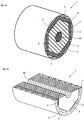
- Fig. 1a shows an axial section of a permanent magnet rotor 1, with a return body 2, which consists of a stack of hexagonal electric sheets.
- the return body 2 also has a shaft recess 10, which serves for attachment to a rotor shaft.
- Plate-shaped permanent magnets 3 adjoin the six surfaces of the hexagonal laminated core (return body 2). These permanent magnets 3 are surrounded by a filled with hard magnetic material plastic compound 5, which is joined by an arching process. During the primary forming the permanent magnets are already biased, whereby the hard magnetic material with which the plastic material is filled aligns with the magnetic field lines of the permanent magnets.
- the outer contour of the permanent magnet rotor 1 is here completely formed by the plastic compound 5 and has a cylinder jacket-shaped outer contour 6. Between the permanent magnet remains a gap which is filled by the plastic compound 5.
- Fig. 1b shows a radial section of the first embodiment, with the return body 2, the permanent magnet 3, the plastic mass 5 and the shaft recess 10th
- Fig. 2a shows an axial section of a permanent magnet rotor 1, with a return body 2, which consists of a stack of hexagonal electric sheets.
- the return body 2 also has a shaft recess 10, which serves for attachment to a rotor shaft.
- Plate-shaped permanent magnets 3 adjoin the six surfaces of the hexagonal laminated core (return body 2). These permanent magnets 3 are surrounded by a filled with hard magnetic material plastic compound 5, which is joined by an arching process. During the primary forming the permanent magnets are already biased, whereby the hard magnetic material with which the plastic material is filled aligns with the magnetic field lines of the permanent magnets.
- the outer contour of the permanent magnet rotor 1 is here completely formed by the plastic compound 5 and has a polygonal outer contour.
- Fig. 1a flattenings 7 are provided here, which are aligned parallel to the permanent magnet 3.
- Fig. 2b shows a radial section, with the return body 2, the permanent magnet 3, the plastic mass 5, the flats 7 and the shaft recess 10th
- Fig. 3a shows an axial section of a first embodiment of a permanent magnet rotor 1, with a return body 2, which consists of a stack of hexagonal electric sheets.
- the return body 2 also has a shaft recess 10, which serves for attachment to a rotor shaft and in which the axis 11 of the permanent magnet rotor 1 extends.
- Plate-shaped permanent magnets 3 adjoin the six surfaces of the hexagonal laminated core (return body 2). These permanent magnets 3 are surrounded by a filled with hard magnetic material plastic compound 5, which is joined by an arching process. During the primary forming the permanent magnets are already biased, whereby the hard magnetic material with which the plastic material is filled aligns with the magnetic field lines of the permanent magnets.
- the outer contour of the permanent magnet rotor 1 is here completely formed by the plastic compound 5 and has a partially cylindrical jacket-shaped outer contour 6. Between the permanent magnet remains a gap which is filled by the plastic compound 5.
- grooves 8 are provided, which are aligned in the radial direction parallel to the permanent magnet 3, but has a Schränkungswinkel a with axis-parallel lines 4.
- Fig. 3b shows a radial section of the first embodiment, with the return body 2, the permanent magnet 3, the plastic mass 5, the grooves 8 and the shaft recess 10th
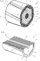
- Fig. 4a shows an axial section of a permanent magnet rotor 1, with a return body 2, which consists of a stack of star-shaped electrical steel sheets.
- the return body 2 also has a shaft recess 10, which serves for attachment to a rotor shaft.
- At the laminated core (return body 2) close plate-shaped permanent magnets 3 at.
- Each of these permanent magnets 3 is followed by volume areas of a plastic compound 5 filled with hard magnetic material which is joined by a prototyping process. During the original molding are the
- Permanent magnets already pre-magnetized, whereby the hard magnetic material with which the plastic material is filled aligns with the magnetic field lines of the permanent magnets.
- the outer contour of the permanent magnet rotor 1 is partially formed by the plastic compound 5 and partially by projections 9, which are integral with the return body 2, wherein they form a cylindrical outer contour 6 with each other.
- the plastic compound 5 is divided into a number of permanent magnets corresponding number separated space regions.
- Fig. 4b shows a radial section, with the return body 2, the permanent magnet 3, the plastic mass 5, the projections 9 and the shaft recess 10th
- Fig. 5a shows an axial section of a second embodiment of a permanent magnet rotor 1, with a return body 2, which consists of a stack of star-shaped electrical steel sheets.
- the return body 2 also has a shaft recess 10, which serves for attachment to a rotor shaft.
- At the laminated core (return body 2) close plate-shaped permanent magnets 3 at.
- Each of these permanent magnets 3 is followed by volume regions of a plastic compound 5 filled with hard magnetic material, which is joined by a primary shaping process. During the primary forming the permanent magnets are already biased, whereby the hard magnetic material with which the plastic material 5 is filled aligns with the magnetic field lines of the permanent magnets.
- the outer contour of the permanent magnet rotor 1 is partially formed by the plastic compound 5 and partially by projections 9, which are integral with the return body 2.
- the plastic compound 5 is divided into a number of permanent magnets corresponding number separated space regions and has axially parallel grooves 8.
- Fig. 5b shows a radial section of the second embodiment, with the return body 2, the permanent magnet 3, the plastic mass 5, the projections 9, the grooves 8 and the shaft recess 10th
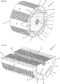
- Fig. 6a shows an axial section of a third embodiment of a permanent magnet rotor 1, with a return body 2, which consists of a stack of star-shaped electrical steel sheets.
- the return body 2 also has a shaft recess 10, which for attachment to a rotor shaft serves.
- At the laminated core (return body 2) close plate-shaped permanent magnets 3 at.
- Each of these permanent magnets 3 is followed by volume regions of a plastic compound 5 filled with hard magnetic material, which is joined by a primary shaping process. During the primary forming the permanent magnets are already biased, whereby the hard magnetic material with which the plastic material 5 is filled aligns with the magnetic field lines of the permanent magnets.
- the outer contour of the permanent magnet rotor 1 is partially formed by the plastic compound 5 and partially by projections 9, which are integral with the return body 2.
- the plastic compound 5 is divided into a number of permanent magnets corresponding number separated space regions and has grooves 8.
- the grooves 8 are inclined with respect to axially parallel lines 4 by a Schränkungswinkel a.
- Fig. 6b shows a radial section of the third embodiment, with the return body 2, the permanent magnet 3, the plastic mass 5, the projections 9, the grooves 8 and the shaft recess 10th
Landscapes
- Engineering & Computer Science (AREA)
- Power Engineering (AREA)
- Manufacturing & Machinery (AREA)
- Permanent Field Magnets Of Synchronous Machinery (AREA)
- Iron Core Of Rotating Electric Machines (AREA)
Description
- Die Erfindung betrifft einen Permanentmagnetrotor (1) eines Elektromotors, bestehend aus einem Rückschlusskörper (2), einer Vielzahl von auf dem Umfang des Rückschlusskörpers (2) verteilten und mit Abstand voneinander angeordneten gesinterten Permanentmagneten (3), an welche eine mit hartmagnetischem Material gefüllte Kunststoffmasse (5) anschließt.
- Aus der
US 5,488,260 B1 ist ein Permanentmagnetrotor bekannt, bei dem auf einem Basiskörper bogenförmige Permanentmagnete angeordnet sind und durch ein mit Permanentmagnetmaterial gefülltes Kunststoff- oder Harzmaterial umspritzt sind. Die Herstellung von bogenförmigen Permanentmagneten ist nur mit erheblichen Aufwand mit ausreichender Maßgenauigkeit herstellbar. Maßnahmen zur Geräuschminderung durch eine spezielle Formgebung der Polflächen, z.B. Schränkungsnuten sind hiermit kaum möglich zumindest nicht mit vertretbarem Aufwand. - Aus der nächstliegenden
WO 01/11756 A1 - Die
GB 2 258 566 - Aus der
US 4 777 397 A ist ein Permanentmagnetrotor eines Elektromotors - Die
WO 2013/104998 A2 offenbart einen weiteren Permanentmagnetrotor eines Elektromotors. - Aufgabe der vorliegenden Erfindung ist es daher bei einem gattungsgemäßen Permanentmagnetrotor dafür Sorge zu tragen, dass dieser einfach und wirtschaftlich herstellbar ist und zudem große Freiheitsgrade hinsichtlich der Gestaltung der Polflächen aufweist, wobei eine hohe Festigkeit und Sicherheit der mechanischen Verbindung zwischen den Permanentmagneten und dem Rückschlusskörper gewährleistet ist.
- Diese Aufgabe wird erfindungsgemäß durch die Ansprüche 1 und 9 gelöst. Da die Permanentmagnete plattenförmige bis quaderförmige Blockmagnete sind, lassen sich diese mit geringem Aufwand sehr genau in großen Mengen schleifen. Durch die Ausrichtung des hartmagnetischen Materials der Kunststoffmasse an den Magnetfeldlinien der vormagnetisierten Permanentmagnete verstärken sich das Magnetfeld des Permanentmagnetrotors und damit der Wirkungsgrad des Elektromotors. Zudem sind Nuten in der Außenkontur der Kunststoffmasse vorgesehen.
- Weiterbildungen der Erfindung werden nachfolgend anhand der Unteransprüche näher dargestellt.
- Zweckmäßigerweise bildet die Kunststoffmasse eine zylindrische Außenkontur. Aufgrund von Geräuschreduzierungserfordernissen kann vorgesehen sein, dass die Kunststoffmasse eine Vielzahl von Abflachungen an der radialen Außenkontur aufweist.
- Eine weitere Verbesserung des Rastmoments des Permanentmagnetrotors wird dadurch erreicht, dass die Nuten mit achsparallelen Linien auf der Außenkontur einen Schränkungswinkel bilden.
- Zur Verbesserung der mechanischen Festigkeit ist vorgesehen, dass der Rückschlusskörper zwischen den voneinander beabstandeten Permanentmagneten radial ausgerichtete Vorsprünge aufweist, wobei diese Vorsprünge sich vorzugsweise radial nach außen verbreitern. Insbesondere sollen die Magnete jeweils breiter sein als die lichte Weite zwischen zwei benachbarten Vorsprüngen im radial außerhalb des von den Permanentmagneten eingenommenen Raumbereichs. Die Kunststoffmasse ist durch die Vorsprünge in eine Vielzahl von Raumbereichen aufgeteilt und geht mit den Vorsprüngen eine formschlüssige Verbindung ein, wobei diese eine schwalbenschwanzartige Kontur aufweisen.
- Eine zweite Lösung der Aufgabe ergibt sich durch ein Verfahren zur Herstellung eines Permanentmagnetrotors. Dieses Verfahren umfasst die Verfahrensschritte: a) Bereitstellen eines Rückschlusskörpers; b) Anordnen von vormagnetisierten Permanentmagneten (3) auf dem Rückschlusskörper (2); c) Umspritzen des Rückschlusskörpers (2) und der Permanentmagnete (3) durch eine mit hartmagnetischem Material gefüllte Kunststoffmasse (5), wobei das hartmagnetische Material an den Magnetfeldern der vormagnetisierten Permanentmagnete (3) ausgerichtet wird.
- Beispiele und Ausführungsbeispiele der Erfindung werden nachfolgend anhand der Zeichnung näher erläutert. Es zeigen:
-
Fig. 1a einen Axialschnitt eines Permanentmagnetrotors, -
Fig. 1b einen Radialschnitt, -
Fig. 2a einen Axialschnitt eines Permanentmagnetrotors, -
Fig. 2b einen Radialschnitt, -
Fig. 3a einen Axialschnitt einer ersten Ausführungsform eines Permanentmagnetrotors, -
Fig. 3b einen Radialschnitt der ersten Ausführungsform, -
Fig. 4a einen Axialschnitt eines Permanentmagnetrotors, -
Fig. 4b einen Radialschnitt, -
Fig. 5a einen Axialschnitt einer zweiten Ausführungsform eines Permanentmagnetrotors, -
Fig. 5b einen Radialschnitt der zweiten Ausführungsform, -
Fig. 6a einen Axialschnitt einer dritten Ausführungsform eines Permanentmagnetrotors und -
Fig. 6b einen Radialschnitt der dritten Ausführungsform. -
Fig. 1a zeigt einen Axialschnitt eines Permanentmagnetrotors 1, mit einem Rückschlusskörper 2, welcher aus einem Stapel von sechskantförmigen Elektroblechen besteht. Der Rückschlusskörper 2 weist zudem eine Wellenausnehmung 10 auf, welche zur Befestigung auf einer Rotorwelle dient. An die sechs Flächen des sechskantförmigen Blechpakets (Rückschlusskörper 2) schließen sich plattenförmige Permanentmagnete 3 an. Diese Permanentmagnete 3 sind von einer mit hartmagnetischem Material gefüllte Kunststoffmasse 5 umgeben, welche durch einen Urformvorgang gefügt ist. Während des Urformens sind die Permanentmagnete bereits vormagnetisiert, wodurch sich das hartmagnetische Material mit welchem die Kunststoffmasse gefüllt ist an den Magnetfeldlinien der Permanentmagnete ausrichtet. Die Außenkontur des Permanentmagnetrotors 1 wird hier vollumfänglich durch die Kunststoffmasse 5 gebildet und weist eine zylindermantelförmige Außenkontur 6 auf. Zwischen den Permanentmagneten verbleibt eine Lücke, welche durch die Kunststoffmasse 5 ausgefüllt ist.Fig. 1b zeigt einen Radialschnitt der ersten Ausführungsform, mit dem Rückschlusskörper 2, den Permanentmagneten 3, der Kunststoffmasse 5 und der Wellenausnehmung 10. -
Fig. 2a zeigt einen Axialschnitt eines Permanentmagnetrotors 1, mit einem Rückschlusskörper 2, welcher aus einem Stapel von sechskantförmigen Elektroblechen besteht. Der Rückschlusskörper 2 weist zudem eine Wellenausnehmung 10 auf, welche zur Befestigung auf einer Rotorwelle dient. An die sechs Flächen des sechskantförmigen Blechpakets (Rückschlusskörper 2) schließen sich plattenförmige Permanentmagnete 3 an. Diese Permanentmagnete 3 sind von einer mit hartmagnetischem Material gefüllte Kunststoffmasse 5 umgeben, welche durch einen Urformvorgang gefügt ist. Während des Urformens sind die Permanentmagnete bereits vormagnetisiert, wodurch sich das hartmagnetische Material mit welchem die Kunststoffmasse gefüllt ist an den Magnetfeldlinien der Permanentmagnete ausrichtet. Die Außenkontur des Permanentmagnetrotors 1 wird hier vollumfänglich durch die Kunststoffmasse 5 gebildet und weist eine polygonartige Außenkontur auf. Zwischen den Permanentmagneten verbleibt eine Lücke, welche durch die Kunststoffmasse 5 ausgefüllt ist. Im Unterschied zuFig. 1a sind hier Abflachungen 7 vorgesehen, welche parallel zu den Permanentmagneten 3 ausgerichtet sind.Fig. 2b zeigt einen Radialschnitt, mit dem Rückschlusskörper 2, den Permanentmagneten 3, der Kunststoffmasse 5, den Abflachungen 7 und der Wellenausnehmung 10. -
Fig. 3a zeigt einen Axialschnitt einer ersten Ausführungsform eines Permanentmagnetrotors 1, mit einem Rückschlusskörper 2, welcher aus einem Stapel von sechskantförmigen Elektroblechen besteht. Der Rückschlusskörper 2 weist zudem eine Wellenausnehmung 10 auf, welche zur Befestigung auf einer Rotorwelle dient und in welcher die Achse 11 des Permanentmagnetrotors 1 verläuft. An die sechs Flächen des sechskantförmigen Blechpakets (Rückschlusskörper 2) schließen sich plattenförmige Permanentmagnete 3 an. Diese Permanentmagnete 3 sind von einer mit hartmagnetischem Material gefüllte Kunststoffmasse 5 umgeben, welche durch einen Urformvorgang gefügt ist. Während des Urformens sind die Permanentmagnete bereits vormagnetisiert, wodurch sich das hartmagnetische Material mit welchem die Kunststoffmasse gefüllt ist an den Magnetfeldlinien der Permanentmagnete ausrichtet. Die Außenkontur des Permanentmagnetrotors 1 wird hier vollumfänglich durch die Kunststoffmasse 5 gebildet und weist eine partiell zylindermantelförmige Außenkontur 6 auf. Zwischen den Permanentmagneten verbleibt eine Lücke, welche durch die Kunststoffmasse 5 ausgefüllt ist. Es sind hier Nuten 8 vorgesehen, welche in Radialrichtung parallel zu den Permanentmagneten 3 ausgerichtet sind, aber einen Schränkungswinkel a mit achsparallelen Linien 4 aufweist.Fig. 3b zeigt einen Radialschnitt der ersten Ausführungsform, mit dem Rückschlusskörper 2, den Permanentmagneten 3, der Kunststoffmasse 5, den Nuten 8 und der Wellenausnehmung 10. -
Fig. 4a zeigt einen Axialschnitt eines Permanentmagnetrotors 1, mit einem Rückschlusskörper 2, welcher aus einem Stapel von sternförmigen Elektroblechen besteht. Der Rückschlusskörper 2 weist zudem eine Wellenausnehmung 10 auf, welche zur Befestigung auf einer Rotorwelle dient. An das Blechpakets (Rückschlusskörper 2) schließen sich plattenförmige Permanentmagnete 3 an. An diese Permanentmagnete 3 schließen sich jeweils Volumenbereiche einer mit hartmagnetischem Material gefüllten Kunststoffmasse 5 an, welche durch einen Urformvorgang gefügt ist. Während des Urformens sind die - Permanentmagnete bereits vormagnetisiert, wodurch sich das hartmagnetische Material mit welchem die Kunststoffmasse gefüllt ist an den Magnetfeldlinien der Permanentmagnete ausrichtet. Die Außenkontur des Permanentmagnetrotors 1 wird teilweise von der Kunststoffmasse 5 und teilweise von Vorsprüngen 9 gebildet, die mit dem Rückschlusskörper 2 einstückig sind, wobei sie miteinander eine zylindermantelförmige Außenkontur 6 bilden. Die Kunststoffmasse 5 ist in eine der Anzahl der Permanentmagnete entsprechende Anzahl voneinander getrennter Raumbereiche aufgeteilt.
Fig. 4b zeigt einen Radialschnitt, mit dem Rückschlusskörper 2, den Permanentmagneten 3, der Kunststoffmasse 5, den Vorsprüngen 9 und der Wellenausnehmung 10. -
Fig. 5a zeigt einen Axialschnitt einer zweiten Ausführungsform eines Permanentmagnetrotors 1, mit einem Rückschlusskörper 2, welcher aus einem Stapel von sternförmigen Elektroblechen besteht. Der Rückschlusskörper 2 weist zudem eine Wellenausnehmung 10 auf, welche zur Befestigung auf einer Rotorwelle dient. An das Blechpakets (Rückschlusskörper 2) schließen sich plattenförmige Permanentmagnete 3 an. An diese Permanentmagnete 3 schließen sich jeweils Volumenbereiche einer mit hartmagnetischem Material gefüllten Kunststoffmasse 5 an, welche durch einen Urformvorgang gefügt ist. Während des Urformens sind die Permanentmagnete bereits vormagnetisiert, wodurch sich das hartmagnetische Material mit welchem die Kunststoffmasse 5 gefüllt ist an den Magnetfeldlinien der Permanentmagnete ausrichtet. Die Außenkontur des Permanentmagnetrotors 1 wird teilweise von der Kunststoffmasse 5 und teilweise von Vorsprüngen 9 gebildet, die mit dem Rückschlusskörper 2 einstückig sind. Die Kunststoffmasse 5 ist in eine der Anzahl der Permanentmagnete entsprechende Anzahl voneinander getrennter Raumbereiche aufgeteilt und weist achsparallele Nuten 8 auf.Fig. 5b zeigt einen Radialschnitt der zweiten Ausführungsform, mit dem Rückschlusskörper 2, den Permanentmagneten 3, der Kunststoffmasse 5, den Vorsprüngen 9, den Nuten 8 und der Wellenausnehmung 10. -
Fig. 6a zeigt einen Axialschnitt einer dritten Ausführungsform eines Permanentmagnetrotors 1, mit einem Rückschlusskörper 2, welcher aus einem Stapel von sternförmigen Elektroblechen besteht. Der Rückschlusskörper 2 weist zudem eine Wellenausnehmung 10 auf, welche zur Befestigung auf einer Rotorwelle dient. An das Blechpakets (Rückschlusskörper 2) schließen sich plattenförmige Permanentmagnete 3 an. An diese Permanentmagnete 3 schließen sich jeweils Volumenbereiche einer mit hartmagnetischem Material gefüllten Kunststoffmasse 5 an, welche durch einen Urformvorgang gefügt ist. Während des Urformens sind die Permanentmagnete bereits vormagnetisiert, wodurch sich das hartmagnetische Material mit welchem die Kunststoffmasse 5 gefüllt ist an den Magnetfeldlinien der Permanentmagnete ausrichtet. Die Außenkontur des Permanentmagnetrotors 1 wird teilweise von der Kunststoffmasse 5 und teilweise von Vorsprüngen 9 gebildet, die mit dem Rückschlusskörper 2 einstückig sind. Die Kunststoffmasse 5 ist in eine der Anzahl der Permanentmagnete entsprechende Anzahl voneinander getrennter Raumbereiche aufgeteilt und weist Nuten 8 auf. Im Gegensatz zur zweiten Ausführungsform sind die Nuten 8 gegenüber achsparallelen Linien 4 um einen Schränkungswinkel a geneigt.Fig. 6b zeigt einen Radialschnitt der dritten Ausführungsform, mit dem Rückschlusskörper 2, den Permanentmagneten 3, der Kunststoffmasse 5, den Vorsprüngen 9, den Nuten 8 und der Wellenausnehmung 10. - In den
Figuren 1b ,2b ,3b ,4b ,5b und6b ist weiter zu erkennen, dass sich die Füllmasse 5 partiell auch zwischen den Rückschlusskörper und den Permanentmagneten 3 erstreckt. Dies ist dadurch begründet, dass Kanten der Permanentmagnete abgerundet sind. -
- 1
- Permanentmagnetrotor
- 2
- Rückschlusskörper
- 3
- Magnet
- 4
- achsparallele Linie
- 5
- gefüllte Kunststoffmasse
- 6
- Außenkontur
- 7
- Abflachungen
- 8
- Nuten
- 9
- Vorsprünge
- 10
- Wellenausnehmung
- 11
- Achse
Claims (9)
- Permanentmagnetrotor (1) eines Elektromotors, bestehend aus einem Rückschlusskörper (2), einer Vielzahl von auf dem Umfang des Rückschlusskörpers (2) verteilten und mit Abstand voneinander angeordneten gesinterten Permanentmagneten (3), wobei die Permanentmagnete (3) plattenförmige bis quaderförmige Blockmagnete sind, dadurch gekennzeichnet, dass an die Permanentmagnete (3) eine mit hartmagnetischem Material gefüllte Kunststoffmasse anschließt und das hartmagnetische Material in der Kunststoffmasse (5) durch die Kraftwirkung der Magnete (3) an deren Magnetfeldlinien ausgerichtet ist, wobei die Kunststoffmasse (5) in ihrer Außenkontur (6) Nuten (8) aufweist.
- Permanentmagnetrotor nach Anspruch 1, dadurch gekennzeichnet, dass die Kunststoffmasse (5) eine zylindrische Außenkontur (6) bildet.
- Permanentmagnetrotor nach Anspruch 1, dadurch gekennzeichnet, dass die Kunststoffmasse (5) eine Vielzahl von Abflachungen (7) an der radialen Außenkontur aufweist.
- Permanentmagnetrotor nach Anspruch 1, dadurch gekennzeichnet, dass die Nuten (8) mit achsparallelen Linien auf der Außenkontur einen Schränkungswinkel bilden.
- Permanentmagnetrotor nach Anspruch 1, dadurch gekennzeichnet, dass der Rückschlusskörper (2) zwischen den voneinander beabstandeten Magneten (3) radial ausgerichtete Vorsprünge (9) aufweist.
- Permanentmagnetrotor nach Anspruch 5, dadurch gekennzeichnet, dass sich die Vorsprünge (9) radial nach außen verbreitern.
- Permanentmagnetrotor nach Anspruch 6, dadurch gekennzeichnet, dass die Permanentmagnete (3) jeweils breiter als die lichte Weite zwischen zwei benachbarten Vorsprüngen (9) im radial außerhalb des von den Magneten (3) eingenommenen Raumbereich sind.
- Permanentmagnetrotor nach Anspruch 5,6 oder 7, dadurch gekennzeichnet, dass die Kunststoffmasse (5) durch die Vorsprünge (9) in eine Vielzahl von Raumbereichen aufgeteilt ist und mit den Vorsprüngen (9) eine formschlüssige Verbindung eingeht.
- Verfahren zur Herstellung eines Permanentmagnetrotors nach einem der Ansprüche 1-8, gekennzeichnet durch folgende Verfahrensschritte: a) Bereitstellen eines Rückschlusskörpers; b) Anordnen von vormagnetisierten Permanentmagneten (3) auf dem Rückschlusskörper (2); c) Umspritzen des Rückschlusskörpers (2) mit den Permanentmagneten (3) durch eine mit hartmagnetischem Material gefüllte Kunststoffmasse (5), wobei das hartmagnetische Material an den Magnetfeldlinien der vormagnetisierten Permanentmagnete (3) ausgerichtet wird.
Applications Claiming Priority (2)
| Application Number | Priority Date | Filing Date | Title |
|---|---|---|---|
| DE102015206100.0A DE102015206100A1 (de) | 2015-04-02 | 2015-04-02 | Permanentmagnetrotor |
| PCT/DE2016/200146 WO2016155727A1 (de) | 2015-04-02 | 2016-03-21 | Permanentmagnetrotor |
Publications (2)
| Publication Number | Publication Date |
|---|---|
| EP3278422A1 EP3278422A1 (de) | 2018-02-07 |
| EP3278422B1 true EP3278422B1 (de) | 2019-08-21 |
Family
ID=55806110
Family Applications (1)
| Application Number | Title | Priority Date | Filing Date |
|---|---|---|---|
| EP16717830.0A Active EP3278422B1 (de) | 2015-04-02 | 2016-03-21 | Permanentmagnetrotor |
Country Status (7)
| Country | Link |
|---|---|
| US (1) | US20180019630A1 (de) |
| EP (1) | EP3278422B1 (de) |
| KR (1) | KR102081800B1 (de) |
| CN (1) | CN107438936B (de) |
| DE (1) | DE102015206100A1 (de) |
| ES (1) | ES2748752T3 (de) |
| WO (1) | WO2016155727A1 (de) |
Families Citing this family (6)
| Publication number | Priority date | Publication date | Assignee | Title |
|---|---|---|---|---|
| CN106787328B (zh) * | 2016-12-30 | 2023-12-22 | 北京良明宇航节能动力装备技术开发中心 | 一种盘式电机转子 |
| DE102017207158A1 (de) | 2017-04-27 | 2018-10-31 | Brose Fahrzeugteile GmbH & Co. Kommanditgesellschaft, Würzburg | Magnetaufnahmemodul für einen Rotor und Rotor einer elektrischen Maschine sowie Verfahren zur jeweiligen Herstellung |
| PL232571B1 (pl) * | 2018-04-11 | 2019-06-28 | Instytut Napedow I Masz Elektrycznych Komel | Wirnik maszyny z magnesami trwałymi |
| EP3595132A1 (de) * | 2018-07-13 | 2020-01-15 | Siemens Aktiengesellschaft | Materiallage für hohe drehzahlen und methode zu dessen herstellung |
| WO2020095823A1 (ja) * | 2018-11-09 | 2020-05-14 | アイシン・エィ・ダブリュ株式会社 | 回転電機用ロータコア |
| CN114744790B (zh) * | 2022-05-06 | 2026-03-27 | 厦门钨业股份有限公司 | 一种用于永磁同步电机的转子和永磁同步电机 |
Family Cites Families (14)
| Publication number | Priority date | Publication date | Assignee | Title |
|---|---|---|---|---|
| JPS61128754A (ja) * | 1984-11-26 | 1986-06-16 | Shinko Electric Co Ltd | 永久磁石式回転子 |
| US4777397A (en) * | 1986-08-15 | 1988-10-11 | Marathon Electric Manufacturing Corp. | Permanent magnet generator apparatus including a consequent pole rotor |
| GB2217924B (en) * | 1988-04-25 | 1992-10-07 | Matsushita Electric Works Ltd | Permanent magnet rotor |
| GB2258566B (en) | 1991-08-07 | 1994-12-21 | Johnson Electric Sa | Permanent magnet rotor |
| ITTO990154U1 (it) * | 1999-08-06 | 2001-02-06 | Bitron Spa | Motore elettrico per la pompa della benzina di un motore a combustioneinterna. |
| US6856051B2 (en) * | 2001-10-03 | 2005-02-15 | Delphi Technologies, Inc. | Manufacturing method and composite powder metal rotor assembly for circumferential type interior permanent magnet machine |
| EP1536543B1 (de) * | 2002-06-20 | 2013-03-13 | Kabushiki Kaisha Toshiba | Rotor für einen permanentmagnetmotor des typs mit externem rotor |
| JP2006086319A (ja) * | 2004-09-16 | 2006-03-30 | Mitsubishi Electric Corp | リング型焼結磁石 |
| DE102006036392A1 (de) * | 2006-03-31 | 2007-11-22 | Aweco Appliance Systems Gmbh & Co. Kg | Elektromotor mit Rotor, Rotor und Verfahren zur Herstellung eines Rotors für einen Elektromotor |
| CN201336593Y (zh) * | 2008-12-30 | 2009-10-28 | 卧龙电气集团股份有限公司 | 塑封永磁转子结构 |
| DE102010014597A1 (de) * | 2010-04-09 | 2011-10-13 | Continental Automotive Gmbh | Rotor |
| SI23980A (sl) * | 2012-01-10 | 2013-07-31 | Nela Razvojni Center D.O.O. Podružnica Otoki | Rotor s trajnimi magneti sinhronega elektromotorja |
| WO2014082840A2 (en) * | 2012-11-30 | 2014-06-05 | Arcelik Anonim Sirketi | A spoke permanent magnet rotor |
| DE102012112228A1 (de) * | 2012-12-13 | 2014-06-18 | Hanning Elektro-Werke Gmbh & Co. Kg | Rotor sowie Elektromotor |
-
2015
- 2015-04-02 DE DE102015206100.0A patent/DE102015206100A1/de not_active Withdrawn
-
2016
- 2016-03-21 ES ES16717830T patent/ES2748752T3/es active Active
- 2016-03-21 CN CN201680018843.1A patent/CN107438936B/zh not_active Expired - Fee Related
- 2016-03-21 WO PCT/DE2016/200146 patent/WO2016155727A1/de not_active Ceased
- 2016-03-21 KR KR1020177031168A patent/KR102081800B1/ko not_active Expired - Fee Related
- 2016-03-21 EP EP16717830.0A patent/EP3278422B1/de active Active
-
2017
- 2017-09-27 US US15/716,688 patent/US20180019630A1/en not_active Abandoned
Non-Patent Citations (1)
| Title |
|---|
| None * |
Also Published As
| Publication number | Publication date |
|---|---|
| ES2748752T3 (es) | 2020-03-17 |
| KR102081800B1 (ko) | 2020-02-26 |
| US20180019630A1 (en) | 2018-01-18 |
| CN107438936A (zh) | 2017-12-05 |
| WO2016155727A1 (de) | 2016-10-06 |
| EP3278422A1 (de) | 2018-02-07 |
| KR20170132826A (ko) | 2017-12-04 |
| CN107438936B (zh) | 2020-03-31 |
| DE102015206100A1 (de) | 2016-10-06 |
Similar Documents
| Publication | Publication Date | Title |
|---|---|---|
| EP3278422A1 (de) | Permanentmagnetrotor | |
| EP2960515B1 (de) | Magnetische Kupplung | |
| DE102018128341B4 (de) | Rotor und rotierende elektrische maschine | |
| EP3189582B1 (de) | Rotor einer elektrischen maschine, elektrische maschine und verfahren zum herstellen eines rotors einer elektrischen maschine | |
| DE112017005282B4 (de) | Rotor für rotierende elektrische Maschine | |
| DE112007000201T5 (de) | Geschlitzte Kerne für einen Motorstator, Motorstator, Synchronmotor des Permanentmagnetentyps, und Stanzverfahren durch Stanzstempel für geschlitzte Kerne | |
| DE102016102655A1 (de) | Rotoranordnung mit mehreren magnetlängen für elektrische maschinen und herstellverfahren | |
| EP3381107B1 (de) | Elektroblech mit gedrucktem steg | |
| DE102012221422A1 (de) | Rotor eines Elektromotors und Verfahren zur Herstellung des Rotors | |
| DE102004054277A1 (de) | Rotoranordnung für eine elektrische Maschine und Verfahren zur Herstellung einer Rotoranordnung | |
| DE202010015364U1 (de) | Bürstenloser Elektromotor oder Generator in Schalenbauweise | |
| DE102012022084A1 (de) | Rotoranordnung für eine elektrische Maschine, elektrische Maschine und Verfahren zum Herstellen der Rotoranordnung | |
| DE102016208042A1 (de) | Pol-zu-pol-veränderung der form von spritzgegossenen magneten von innendauermagnetmaschinen | |
| EP3262739A1 (de) | Rotor für eine elektrische maschine mit vorteilhafter drehmomentübertragung sowie entsprechende elektrische maschine | |
| DE102021130152A1 (de) | Rotor für eine Axialfluss-permanenterregte Synchronmaschine und Axialfluss-permanenterregte Synchronmaschine | |
| EP2942858B1 (de) | Rotorblechpaket | |
| DE112017003124B4 (de) | Rotor für rotierende elektrische Permanentmagnetmaschine und rotierende elektrische Permanentmagnetmaschine | |
| EP3157140B1 (de) | Drehmomentoptimierter rotor und elektrokleinmotor mit einem derartigen rotor | |
| DE102011003831A1 (de) | Stator einer elektrischen Maschine | |
| DE102014203945A1 (de) | Statorelement zum Aufbau einer Statoranordnung für eine elektrische Maschine, Statoranordnung und Verfahren zum Aufbau einer Statoranordnung | |
| WO2016162137A1 (de) | Rotoranordnung für eine elektromaschine | |
| EP2705590B1 (de) | Rotor für eine permanentmagnetische maschine | |
| DE202023101234U1 (de) | Rotor aus magnetischen Verbundmaterialien ohne Seltenerdmetalle und permanenterregter Elektromotor | |
| EP3579383A1 (de) | Drehmomentoptimierter mehrpoliger rotor für einen elektromotor | |
| DE102011080008A1 (de) | Elektrische Maschine |
Legal Events
| Date | Code | Title | Description |
|---|---|---|---|
| STAA | Information on the status of an ep patent application or granted ep patent |
Free format text: STATUS: THE INTERNATIONAL PUBLICATION HAS BEEN MADE |
|
| PUAI | Public reference made under article 153(3) epc to a published international application that has entered the european phase |
Free format text: ORIGINAL CODE: 0009012 |
|
| STAA | Information on the status of an ep patent application or granted ep patent |
Free format text: STATUS: REQUEST FOR EXAMINATION WAS MADE |
|
| 17P | Request for examination filed |
Effective date: 20170901 |
|
| AK | Designated contracting states |
Kind code of ref document: A1 Designated state(s): AL AT BE BG CH CY CZ DE DK EE ES FI FR GB GR HR HU IE IS IT LI LT LU LV MC MK MT NL NO PL PT RO RS SE SI SK SM TR |
|
| AX | Request for extension of the european patent |
Extension state: BA ME |
|
| DAV | Request for validation of the european patent (deleted) | ||
| DAX | Request for extension of the european patent (deleted) | ||
| REG | Reference to a national code |
Ref country code: DE Ref legal event code: R079 Ref document number: 502016006196 Country of ref document: DE Free format text: PREVIOUS MAIN CLASS: H02K0001270000 Ipc: H02K0015030000 |
|
| GRAP | Despatch of communication of intention to grant a patent |
Free format text: ORIGINAL CODE: EPIDOSNIGR1 |
|
| STAA | Information on the status of an ep patent application or granted ep patent |
Free format text: STATUS: GRANT OF PATENT IS INTENDED |
|
| RIC1 | Information provided on ipc code assigned before grant |
Ipc: H02K 1/02 20060101ALI20190430BHEP Ipc: H02K 1/27 20060101ALI20190430BHEP Ipc: H02K 15/03 20060101AFI20190430BHEP Ipc: H02K 15/12 20060101ALI20190430BHEP Ipc: H02K 1/04 20060101ALN20190430BHEP |
|
| INTG | Intention to grant announced |
Effective date: 20190517 |
|
| GRAS | Grant fee paid |
Free format text: ORIGINAL CODE: EPIDOSNIGR3 |
|
| GRAA | (expected) grant |
Free format text: ORIGINAL CODE: 0009210 |
|
| STAA | Information on the status of an ep patent application or granted ep patent |
Free format text: STATUS: THE PATENT HAS BEEN GRANTED |
|
| AK | Designated contracting states |
Kind code of ref document: B1 Designated state(s): AL AT BE BG CH CY CZ DE DK EE ES FI FR GB GR HR HU IE IS IT LI LT LU LV MC MK MT NL NO PL PT RO RS SE SI SK SM TR |
|
| REG | Reference to a national code |
Ref country code: GB Ref legal event code: FG4D Free format text: NOT ENGLISH |
|
| REG | Reference to a national code |
Ref country code: CH Ref legal event code: EP |
|
| REG | Reference to a national code |
Ref country code: DE Ref legal event code: R096 Ref document number: 502016006196 Country of ref document: DE |
|
| REG | Reference to a national code |
Ref country code: AT Ref legal event code: REF Ref document number: 1170858 Country of ref document: AT Kind code of ref document: T Effective date: 20190915 |
|
| REG | Reference to a national code |
Ref country code: IE Ref legal event code: FG4D Free format text: LANGUAGE OF EP DOCUMENT: GERMAN |
|
| REG | Reference to a national code |
Ref country code: LT Ref legal event code: MG4D |
|
| REG | Reference to a national code |
Ref country code: NL Ref legal event code: MP Effective date: 20190821 |
|
| PG25 | Lapsed in a contracting state [announced via postgrant information from national office to epo] |
Ref country code: NL Free format text: LAPSE BECAUSE OF FAILURE TO SUBMIT A TRANSLATION OF THE DESCRIPTION OR TO PAY THE FEE WITHIN THE PRESCRIBED TIME-LIMIT Effective date: 20190821 Ref country code: SE Free format text: LAPSE BECAUSE OF FAILURE TO SUBMIT A TRANSLATION OF THE DESCRIPTION OR TO PAY THE FEE WITHIN THE PRESCRIBED TIME-LIMIT Effective date: 20190821 Ref country code: HR Free format text: LAPSE BECAUSE OF FAILURE TO SUBMIT A TRANSLATION OF THE DESCRIPTION OR TO PAY THE FEE WITHIN THE PRESCRIBED TIME-LIMIT Effective date: 20190821 Ref country code: NO Free format text: LAPSE BECAUSE OF FAILURE TO SUBMIT A TRANSLATION OF THE DESCRIPTION OR TO PAY THE FEE WITHIN THE PRESCRIBED TIME-LIMIT Effective date: 20191121 Ref country code: PT Free format text: LAPSE BECAUSE OF FAILURE TO SUBMIT A TRANSLATION OF THE DESCRIPTION OR TO PAY THE FEE WITHIN THE PRESCRIBED TIME-LIMIT Effective date: 20191223 Ref country code: FI Free format text: LAPSE BECAUSE OF FAILURE TO SUBMIT A TRANSLATION OF THE DESCRIPTION OR TO PAY THE FEE WITHIN THE PRESCRIBED TIME-LIMIT Effective date: 20190821 Ref country code: LT Free format text: LAPSE BECAUSE OF FAILURE TO SUBMIT A TRANSLATION OF THE DESCRIPTION OR TO PAY THE FEE WITHIN THE PRESCRIBED TIME-LIMIT Effective date: 20190821 Ref country code: BG Free format text: LAPSE BECAUSE OF FAILURE TO SUBMIT A TRANSLATION OF THE DESCRIPTION OR TO PAY THE FEE WITHIN THE PRESCRIBED TIME-LIMIT Effective date: 20191121 |
|
| PG25 | Lapsed in a contracting state [announced via postgrant information from national office to epo] |
Ref country code: LV Free format text: LAPSE BECAUSE OF FAILURE TO SUBMIT A TRANSLATION OF THE DESCRIPTION OR TO PAY THE FEE WITHIN THE PRESCRIBED TIME-LIMIT Effective date: 20190821 Ref country code: GR Free format text: LAPSE BECAUSE OF FAILURE TO SUBMIT A TRANSLATION OF THE DESCRIPTION OR TO PAY THE FEE WITHIN THE PRESCRIBED TIME-LIMIT Effective date: 20191122 Ref country code: RS Free format text: LAPSE BECAUSE OF FAILURE TO SUBMIT A TRANSLATION OF THE DESCRIPTION OR TO PAY THE FEE WITHIN THE PRESCRIBED TIME-LIMIT Effective date: 20190821 Ref country code: AL Free format text: LAPSE BECAUSE OF FAILURE TO SUBMIT A TRANSLATION OF THE DESCRIPTION OR TO PAY THE FEE WITHIN THE PRESCRIBED TIME-LIMIT Effective date: 20190821 Ref country code: IS Free format text: LAPSE BECAUSE OF FAILURE TO SUBMIT A TRANSLATION OF THE DESCRIPTION OR TO PAY THE FEE WITHIN THE PRESCRIBED TIME-LIMIT Effective date: 20191221 |
|
| REG | Reference to a national code |
Ref country code: ES Ref legal event code: FG2A Ref document number: 2748752 Country of ref document: ES Kind code of ref document: T3 Effective date: 20200317 |
|
| PG25 | Lapsed in a contracting state [announced via postgrant information from national office to epo] |
Ref country code: TR Free format text: LAPSE BECAUSE OF FAILURE TO SUBMIT A TRANSLATION OF THE DESCRIPTION OR TO PAY THE FEE WITHIN THE PRESCRIBED TIME-LIMIT Effective date: 20190821 |
|
| PG25 | Lapsed in a contracting state [announced via postgrant information from national office to epo] |
Ref country code: PL Free format text: LAPSE BECAUSE OF FAILURE TO SUBMIT A TRANSLATION OF THE DESCRIPTION OR TO PAY THE FEE WITHIN THE PRESCRIBED TIME-LIMIT Effective date: 20190821 Ref country code: RO Free format text: LAPSE BECAUSE OF FAILURE TO SUBMIT A TRANSLATION OF THE DESCRIPTION OR TO PAY THE FEE WITHIN THE PRESCRIBED TIME-LIMIT Effective date: 20190821 Ref country code: EE Free format text: LAPSE BECAUSE OF FAILURE TO SUBMIT A TRANSLATION OF THE DESCRIPTION OR TO PAY THE FEE WITHIN THE PRESCRIBED TIME-LIMIT Effective date: 20190821 Ref country code: IT Free format text: LAPSE BECAUSE OF FAILURE TO SUBMIT A TRANSLATION OF THE DESCRIPTION OR TO PAY THE FEE WITHIN THE PRESCRIBED TIME-LIMIT Effective date: 20190821 Ref country code: DK Free format text: LAPSE BECAUSE OF FAILURE TO SUBMIT A TRANSLATION OF THE DESCRIPTION OR TO PAY THE FEE WITHIN THE PRESCRIBED TIME-LIMIT Effective date: 20190821 |
|
| PG25 | Lapsed in a contracting state [announced via postgrant information from national office to epo] |
Ref country code: SM Free format text: LAPSE BECAUSE OF FAILURE TO SUBMIT A TRANSLATION OF THE DESCRIPTION OR TO PAY THE FEE WITHIN THE PRESCRIBED TIME-LIMIT Effective date: 20190821 Ref country code: SK Free format text: LAPSE BECAUSE OF FAILURE TO SUBMIT A TRANSLATION OF THE DESCRIPTION OR TO PAY THE FEE WITHIN THE PRESCRIBED TIME-LIMIT Effective date: 20190821 Ref country code: CZ Free format text: LAPSE BECAUSE OF FAILURE TO SUBMIT A TRANSLATION OF THE DESCRIPTION OR TO PAY THE FEE WITHIN THE PRESCRIBED TIME-LIMIT Effective date: 20190821 Ref country code: IS Free format text: LAPSE BECAUSE OF FAILURE TO SUBMIT A TRANSLATION OF THE DESCRIPTION OR TO PAY THE FEE WITHIN THE PRESCRIBED TIME-LIMIT Effective date: 20200224 |
|
| REG | Reference to a national code |
Ref country code: DE Ref legal event code: R097 Ref document number: 502016006196 Country of ref document: DE |
|
| PLBE | No opposition filed within time limit |
Free format text: ORIGINAL CODE: 0009261 |
|
| STAA | Information on the status of an ep patent application or granted ep patent |
Free format text: STATUS: NO OPPOSITION FILED WITHIN TIME LIMIT |
|
| PG2D | Information on lapse in contracting state deleted |
Ref country code: IS |
|
| 26N | No opposition filed |
Effective date: 20200603 |
|
| REG | Reference to a national code |
Ref country code: DE Ref legal event code: R084 Ref document number: 502016006196 Country of ref document: DE |
|
| PG25 | Lapsed in a contracting state [announced via postgrant information from national office to epo] |
Ref country code: SI Free format text: LAPSE BECAUSE OF FAILURE TO SUBMIT A TRANSLATION OF THE DESCRIPTION OR TO PAY THE FEE WITHIN THE PRESCRIBED TIME-LIMIT Effective date: 20190821 |
|
| PG25 | Lapsed in a contracting state [announced via postgrant information from national office to epo] |
Ref country code: MC Free format text: LAPSE BECAUSE OF FAILURE TO SUBMIT A TRANSLATION OF THE DESCRIPTION OR TO PAY THE FEE WITHIN THE PRESCRIBED TIME-LIMIT Effective date: 20190821 |
|
| REG | Reference to a national code |
Ref country code: CH Ref legal event code: PL |
|
| REG | Reference to a national code |
Ref country code: BE Ref legal event code: MM Effective date: 20200331 |
|
| PG25 | Lapsed in a contracting state [announced via postgrant information from national office to epo] |
Ref country code: LU Free format text: LAPSE BECAUSE OF NON-PAYMENT OF DUE FEES Effective date: 20200321 |
|
| PG25 | Lapsed in a contracting state [announced via postgrant information from national office to epo] |
Ref country code: CH Free format text: LAPSE BECAUSE OF NON-PAYMENT OF DUE FEES Effective date: 20200331 Ref country code: IE Free format text: LAPSE BECAUSE OF NON-PAYMENT OF DUE FEES Effective date: 20200321 Ref country code: LI Free format text: LAPSE BECAUSE OF NON-PAYMENT OF DUE FEES Effective date: 20200331 |
|
| REG | Reference to a national code |
Ref country code: FR Ref legal event code: PLFP Year of fee payment: 6 |
|
| PG25 | Lapsed in a contracting state [announced via postgrant information from national office to epo] |
Ref country code: BE Free format text: LAPSE BECAUSE OF NON-PAYMENT OF DUE FEES Effective date: 20200331 |
|
| GBPC | Gb: european patent ceased through non-payment of renewal fee |
Effective date: 20200321 |
|
| PG25 | Lapsed in a contracting state [announced via postgrant information from national office to epo] |
Ref country code: GB Free format text: LAPSE BECAUSE OF NON-PAYMENT OF DUE FEES Effective date: 20200321 |
|
| PGFP | Annual fee paid to national office [announced via postgrant information from national office to epo] |
Ref country code: FR Payment date: 20210218 Year of fee payment: 6 |
|
| PGFP | Annual fee paid to national office [announced via postgrant information from national office to epo] |
Ref country code: DE Payment date: 20210318 Year of fee payment: 6 |
|
| PGFP | Annual fee paid to national office [announced via postgrant information from national office to epo] |
Ref country code: ES Payment date: 20210407 Year of fee payment: 6 |
|
| REG | Reference to a national code |
Ref country code: AT Ref legal event code: MM01 Ref document number: 1170858 Country of ref document: AT Kind code of ref document: T Effective date: 20210321 |
|
| PG25 | Lapsed in a contracting state [announced via postgrant information from national office to epo] |
Ref country code: MT Free format text: LAPSE BECAUSE OF FAILURE TO SUBMIT A TRANSLATION OF THE DESCRIPTION OR TO PAY THE FEE WITHIN THE PRESCRIBED TIME-LIMIT Effective date: 20190821 Ref country code: CY Free format text: LAPSE BECAUSE OF FAILURE TO SUBMIT A TRANSLATION OF THE DESCRIPTION OR TO PAY THE FEE WITHIN THE PRESCRIBED TIME-LIMIT Effective date: 20190821 |
|
| PG25 | Lapsed in a contracting state [announced via postgrant information from national office to epo] |
Ref country code: MK Free format text: LAPSE BECAUSE OF FAILURE TO SUBMIT A TRANSLATION OF THE DESCRIPTION OR TO PAY THE FEE WITHIN THE PRESCRIBED TIME-LIMIT Effective date: 20190821 |
|
| PG25 | Lapsed in a contracting state [announced via postgrant information from national office to epo] |
Ref country code: AT Free format text: LAPSE BECAUSE OF NON-PAYMENT OF DUE FEES Effective date: 20210321 |
|
| REG | Reference to a national code |
Ref country code: DE Ref legal event code: R119 Ref document number: 502016006196 Country of ref document: DE |
|
| PG25 | Lapsed in a contracting state [announced via postgrant information from national office to epo] |
Ref country code: FR Free format text: LAPSE BECAUSE OF NON-PAYMENT OF DUE FEES Effective date: 20220331 Ref country code: DE Free format text: LAPSE BECAUSE OF NON-PAYMENT OF DUE FEES Effective date: 20221001 |
|
| REG | Reference to a national code |
Ref country code: ES Ref legal event code: FD2A Effective date: 20230428 |
|
| PG25 | Lapsed in a contracting state [announced via postgrant information from national office to epo] |
Ref country code: ES Free format text: LAPSE BECAUSE OF NON-PAYMENT OF DUE FEES Effective date: 20220322 |