EP3276980A1 - Ohrhörer - Google Patents
Ohrhörer Download PDFInfo
- Publication number
- EP3276980A1 EP3276980A1 EP17178927.4A EP17178927A EP3276980A1 EP 3276980 A1 EP3276980 A1 EP 3276980A1 EP 17178927 A EP17178927 A EP 17178927A EP 3276980 A1 EP3276980 A1 EP 3276980A1
- Authority
- EP
- European Patent Office
- Prior art keywords
- sound
- driver
- unit
- delivery tube
- driver units
- Prior art date
- Legal status (The legal status is an assumption and is not a legal conclusion. Google has not performed a legal analysis and makes no representation as to the accuracy of the status listed.)
- Granted
Links
- 210000000613 ear canal Anatomy 0.000 claims abstract description 7
- 238000010276 construction Methods 0.000 abstract 1
- 239000002184 metal Substances 0.000 description 8
- 229910052751 metal Inorganic materials 0.000 description 8
- 239000000463 material Substances 0.000 description 4
- 239000011347 resin Substances 0.000 description 3
- 229920005989 resin Polymers 0.000 description 3
- 230000005236 sound signal Effects 0.000 description 3
- 229910001369 Brass Inorganic materials 0.000 description 2
- XEEYBQQBJWHFJM-UHFFFAOYSA-N Iron Chemical compound [Fe] XEEYBQQBJWHFJM-UHFFFAOYSA-N 0.000 description 2
- 239000010951 brass Substances 0.000 description 2
- 230000002349 favourable effect Effects 0.000 description 2
- 239000007769 metal material Substances 0.000 description 2
- 239000007779 soft material Substances 0.000 description 2
- 210000003454 tympanic membrane Anatomy 0.000 description 2
- 229910001200 Ferrotitanium Inorganic materials 0.000 description 1
- RTAQQCXQSZGOHL-UHFFFAOYSA-N Titanium Chemical compound [Ti] RTAQQCXQSZGOHL-UHFFFAOYSA-N 0.000 description 1
- 230000004308 accommodation Effects 0.000 description 1
- 229920000122 acrylonitrile butadiene styrene Polymers 0.000 description 1
- 230000002238 attenuated effect Effects 0.000 description 1
- 230000015572 biosynthetic process Effects 0.000 description 1
- 230000000694 effects Effects 0.000 description 1
- 229910052742 iron Inorganic materials 0.000 description 1
- 238000002955 isolation Methods 0.000 description 1
- 230000035945 sensitivity Effects 0.000 description 1
- 229910001220 stainless steel Inorganic materials 0.000 description 1
- 239000010935 stainless steel Substances 0.000 description 1
- 239000010936 titanium Substances 0.000 description 1
- 230000001052 transient effect Effects 0.000 description 1
Images


Classifications
-
- H—ELECTRICITY
- H04—ELECTRIC COMMUNICATION TECHNIQUE
- H04R—LOUDSPEAKERS, MICROPHONES, GRAMOPHONE PICK-UPS OR LIKE ACOUSTIC ELECTROMECHANICAL TRANSDUCERS; DEAF-AID SETS; PUBLIC ADDRESS SYSTEMS
- H04R1/00—Details of transducers, loudspeakers or microphones
- H04R1/10—Earpieces; Attachments therefor ; Earphones; Monophonic headphones
- H04R1/1016—Earpieces of the intra-aural type
-
- H—ELECTRICITY
- H04—ELECTRIC COMMUNICATION TECHNIQUE
- H04R—LOUDSPEAKERS, MICROPHONES, GRAMOPHONE PICK-UPS OR LIKE ACOUSTIC ELECTROMECHANICAL TRANSDUCERS; DEAF-AID SETS; PUBLIC ADDRESS SYSTEMS
- H04R1/00—Details of transducers, loudspeakers or microphones
- H04R1/10—Earpieces; Attachments therefor ; Earphones; Monophonic headphones
- H04R1/1058—Manufacture or assembly
-
- H—ELECTRICITY
- H04—ELECTRIC COMMUNICATION TECHNIQUE
- H04R—LOUDSPEAKERS, MICROPHONES, GRAMOPHONE PICK-UPS OR LIKE ACOUSTIC ELECTROMECHANICAL TRANSDUCERS; DEAF-AID SETS; PUBLIC ADDRESS SYSTEMS
- H04R1/00—Details of transducers, loudspeakers or microphones
- H04R1/10—Earpieces; Attachments therefor ; Earphones; Monophonic headphones
- H04R1/1058—Manufacture or assembly
- H04R1/1075—Mountings of transducers in earphones or headphones
-
- H—ELECTRICITY
- H04—ELECTRIC COMMUNICATION TECHNIQUE
- H04R—LOUDSPEAKERS, MICROPHONES, GRAMOPHONE PICK-UPS OR LIKE ACOUSTIC ELECTROMECHANICAL TRANSDUCERS; DEAF-AID SETS; PUBLIC ADDRESS SYSTEMS
- H04R1/00—Details of transducers, loudspeakers or microphones
- H04R1/20—Arrangements for obtaining desired frequency or directional characteristics
- H04R1/22—Arrangements for obtaining desired frequency or directional characteristics for obtaining desired frequency characteristic only
- H04R1/24—Structural combinations of separate transducers or of two parts of the same transducer and responsive respectively to two or more frequency ranges
-
- H—ELECTRICITY
- H04—ELECTRIC COMMUNICATION TECHNIQUE
- H04R—LOUDSPEAKERS, MICROPHONES, GRAMOPHONE PICK-UPS OR LIKE ACOUSTIC ELECTROMECHANICAL TRANSDUCERS; DEAF-AID SETS; PUBLIC ADDRESS SYSTEMS
- H04R1/00—Details of transducers, loudspeakers or microphones
- H04R1/20—Arrangements for obtaining desired frequency or directional characteristics
- H04R1/22—Arrangements for obtaining desired frequency or directional characteristics for obtaining desired frequency characteristic only
- H04R1/28—Transducer mountings or enclosures modified by provision of mechanical or acoustic impedances, e.g. resonator, damping means
- H04R1/2807—Enclosures comprising vibrating or resonating arrangements
- H04R1/2853—Enclosures comprising vibrating or resonating arrangements using an acoustic labyrinth or a transmission line
- H04R1/2857—Enclosures comprising vibrating or resonating arrangements using an acoustic labyrinth or a transmission line for loudspeaker transducers
-
- H—ELECTRICITY
- H04—ELECTRIC COMMUNICATION TECHNIQUE
- H04R—LOUDSPEAKERS, MICROPHONES, GRAMOPHONE PICK-UPS OR LIKE ACOUSTIC ELECTROMECHANICAL TRANSDUCERS; DEAF-AID SETS; PUBLIC ADDRESS SYSTEMS
- H04R25/00—Deaf-aid sets, i.e. electro-acoustic or electro-mechanical hearing aids; Electric tinnitus maskers providing an auditory perception
- H04R25/60—Mounting or interconnection of hearing aid parts, e.g. inside tips, housings or to ossicles
- H04R25/604—Mounting or interconnection of hearing aid parts, e.g. inside tips, housings or to ossicles of acoustic or vibrational transducers
-
- H—ELECTRICITY
- H04—ELECTRIC COMMUNICATION TECHNIQUE
- H04R—LOUDSPEAKERS, MICROPHONES, GRAMOPHONE PICK-UPS OR LIKE ACOUSTIC ELECTROMECHANICAL TRANSDUCERS; DEAF-AID SETS; PUBLIC ADDRESS SYSTEMS
- H04R2201/00—Details of transducers, loudspeakers or microphones covered by H04R1/00 but not provided for in any of its subgroups
- H04R2201/10—Details of earpieces, attachments therefor, earphones or monophonic headphones covered by H04R1/10 but not provided for in any of its subgroups
- H04R2201/105—Manufacture of mono- or stereophonic headphone components
Definitions
- the present invention relates to in-ear headphones, such as canal headphones (ear plug type), which enable a reproduced sound from driver units to propagate faithfully.
- a canal earphone includes a driver unit that reproduces sound waves on receiving an audio signal, a unit case that accommodates the driver unit, a sound delivery tube that communicates with the unit case and leads a reproduced sound (sound waves) to users' ear canal, and an eartip that is provided to cover the tip end portion of the sound delivery tube.
- Such a canal earphone has an advantage of high isolation not affected by ambient noises, because the eartip is worn in close contact with the users' ear canal.
- BA driver units balanced armature driver units
- the BA driver unit has a unit case housing components such as a magnet, a coil, an armature and a diaphragm.
- the armature (a piece of iron plate) is vibrated by a drive current corresponding to an audio signal and vibration of the armature is transmitted to the diaphragm through a drive rod to reproduce sound waves.
- the diaphragm of the BA driver unit can vibrate faithfully to the audio signal without being subjected to air resistance because the diaphragm is made of a rigid metal plate. Consequently, the driver has characteristics of a sufficient transient response and of a high sound pressure level of sound output corresponding to an input signal, i.e., high sensitivity.
- a multiple BA driver unit is employed that is a combination of special driver units having separated frequency bands for a high frequency range and a low frequency range.
- Patent Literature 1 U.S. Patent No. 7634099
- Patent Literature 2 U.S. Patent No. 7634099
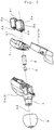
- FIG. 4 shows examples of the canal earphone provided with multiple BA driver units disclosed in Patent Literature 1 and Non-Paten Literature references 1 through 3, showing a state where a part of the unit case is cut away.
- An earphone 1 shown in FIG. 4 is provided with, as basic components, three driver units 2a, 2b and 2c, a unit case that houses the drivers 2a, 2b and 2c, a sound delivery tube 4 that communicates with the unit case 3, and an eartip 5 attached on an outer circumferential surface of the sound delivery tube 4. Inside of the tip part of the sound delivery tube 4, a damper 6 made of acoustic resistance material is attached as needed.
- the driver unit 2a is a BA driver unit for reproducing sound frequencies in a treble range mainly, and a pair of BA units 2b and 2c is for sound frequencies in a mid- and low-range.
- a multiple BA unit is composed of three driver units in the example.
- the driver unit 2c is disposed behind the driver unit 2b and is hidden partly.
- a base member 3a, a cover 3b, and a connecting portion 3c at the center which connects the base member and the cover constitute a unit case that houses respective drive units 2a, 2b, and 2c, and each of which is made of resin material.
- the sound delivery tube 4 is integrally formed with the base member 3a.
- Each of BA driver units 2a, 2b and 2c housed in the unit case 3 has a cuboid unit chassis 21 as an outer shell, and sound from each driver unit is emitted from a sound outlet nozzle 22 which is formed to protrude cylindrically along the longitudinal direction of the cuboid.
- BA driver units 2b and 2c for reproducing sounds in the mid-frequency and low-frequency range are configured to emit sound from a single sound outlet nozzle 22 by connecting each unit chassis 21.
- Each of the BA driver units 2a, 2b and 2c is positioned in the unit case 3 with protecting member 7 made of soft material such as rubber such that the sound emission axes A1 and A2 of each sound outlet nozzle 22 are parallel to each other.
- this configuration is adopted from the view point of an increase of the unit case 3 in size due to accommodation of a plurality of BA units in the case 3, and consideration of a feeling of wearing to user's ear canal or concha of the ear affected by formation of sound delivery tube 4 that communicates with the unit case 3.
- a reproduced sound from the sound outlet nozzle 22 of the each of the BA driver units is reflected in an inner wall of the unit case 3 and arrives at a tympanic membrane of the user through the sound delivery tube 4 communicating with the unit case3.
- the reproduced sound from the sound outlet nozzle 22 of the BA driver unit nearly vertically hits against the wall in the unit case 3 and is reflected and arrives at user's tympanic membrane through the sound delivery tube 4.
- a high-frequency range sound, having a particularly strong directivity, emitted from the BA driver unit is attenuated strongly. Since the size of the diaphragm of the BA unit driver for the high-frequency range sound is small and the amplitude of vibration is also small; therefore, reflection loss in amplitude of high-frequency range sound becomes further larger. In conventional canal-type earphones, the overall frequency response may be deteriorated due to overlapping of the above described factors.
- one of the main objects of the present invention is to provide an earphone having a preferred frequency response by particularly suppressing attenuation of high-frequency components, in an ear phone using a plurality of specific BA driver units.
- Another object of the invention is to provide an earphone wearable to users' ear concha without an uncomfortable feeling, by considering a positional relationship between the BA driver units disposed in the unit case to reduce a size of the unit case 3.
- An earphone for solving the above problem includes: a first driver unit that reproduces sound waves of a high frequency range, a second driver unit that reproduces sound of a frequency range other than the frequency range of the first driver unit, a unit case that houses the first and the second driver units, a sound delivery tube, which communicates with the unit case, that leads the reproduced sound to a user's ear concha, wherein the drivers are disposed such that sound emission axes of the first driver unit and the second driver unit are parallel to each other, and the sound emission axis of the first driver unit is disposed to pass through an opening area of the sound delivery tube.
- balanced armature driver units are used for each of the drive units.
- the first driver unit that reproduces a sound wave of a high frequency range is preferably accommodated in the unit case such that the sound emission axis of the first driver unit is disposed to coincide with a central axis of the opening area of the sound delivery tube.
- the configuration is preferably adopted in which the sound outlet nozzle of the second driver unit is disposed at a retracted position with respect to the position of the sound outlet nozzle of the first drive unit along the sound emission axis parallel to the sound outlet nozzle of the first driver unit.
- the sound delivery tube preferably configures a canal type earphone by having an eartip on an outer circumferential surface thereof.
- An earphone according to the present invention has a feature that the sound emission axis of the drive unit that reproduces sound waves particularly including a high-frequency range is disposed so as to pass through the opening of a sound delivery tube communicating with the unit case.
- This structure allows the sound waves of the high-frequency range in particular to be guided to user' s ear concha as a direct sound without being affected by reflection in the unit case; an earphone achieving a comprehensively preferable frequency response can be provided.
- driver units are disposed in a unit case without requiring to enlarge the size of the unit case in which the driver units are accommodated. This makes it possible to provide an earphone that can be worn on the user's concha without feeling uncomfortable.
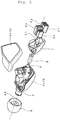
- FIGS. 1 through 3 An earphone according to the present invention will be described on the basis of an embodiment with reference to drawings FIGS. 1 through 3 .
- members, whose functions are the same as those shown in FIG. 4 are denoted by the same reference numerals.
- An earphone shown in FIG. 1 is a canal type earphone.
- This canal type ear phone includes, as basic components, four driver units 2d to 2g, a unit case 3 that houses the driver units 2d to 2g, a sound delivery tube 4 that communicates with the unit case 3 as to lead sound waves to a user' s ear canal, and an eartip attached to an outer circumferential surface of the sound delivery tube 4.
- the unit case 3 is composed of a base member 3a which is a front half of the unit case and a cover 3b which is a rear half of the unit case. Further, a sound delivery tube is integrally formed in the base member 3a, and the unit case is formed by fitting the cover 3b to the base member 3a.
- the unit case 3 is preferably formed of ABS resin, but is not limited thereto.
- an internal space having a predetermined volume is formed inside the unit case 3, and the four driver units 2d to 2g are mounted in the space by being positioned with protecting material 7 that is formed with a soft material such as rubber.
- the four driver units 2d through 2g are composed of BA driver units, respectively and each of cuboid unit chassis 21 constitutes an outer shell, as shown in FIG. 1 .
- the driver unit 2d reproduces high- frequency sounds
- the driver unit 2e reproduces mid-frequency sounds.
- the unit chassis 21 of the driver units 2d and 2e are attached at side surfaces thereof and include a sound outlet nozzle 22 which intrudes in a cylindrical manner along the longitudinal direction.
- the nozzle 22 emits high-and mid-frequency sounds.
- Two driver units 2f, 2g having the same characteristics and reproducing low frequency sounds, are used in order to increase the volume of a low frequency range.
- the unit chassis 21 of the driver units 2f and 2g are attached at side surfaces thereof and include a sound outlet nozzle 22 which intrudes in a cylindrical manner along the longitudinal direction.
- the nozzle 22 emits low-frequency sounds.
- driver units denoted by reference numerals 2d and 2e are referred to as a first driver unit for reproducing sound waves including in a high-frequency range.
- driver units denoted by reference numerals 2f and 2g are referred to as a second driver unit for reproducing sound waves of a frequency range other than those reproduced by the first driver unit.
- four BA driver units form a multiple BA driver unit including the first and second driver units.
- the driver units are located so that a sound emission axis A1 of the first driver unit 2d and 2e and a sound emission axis A2 of the second driver units 2f and 2g are placed in parallel to each other. Further the driver units 2d and 2e that reproduce sound waves including those in a high-frequency range such that the sound emission axis A1 of the first driver units 2d and 2e coincides with the central axis A3 of the opening of a sound delivery tube 4 in the unit case.
- a metal sound delivery tube 8 formed cylindrically with metal materials such as brass, titanium or stainless steel is inscribed with the inner surface of the sound delivery tube 4 made of resin, formed integrally with the unit case 3.
- a damper 6 made of an acoustic resistance material is disposed in the sound delivery tube made of resin to make a contact with a front edge of the metal sound delivery tube 8.
- the metal sound delivery tube 8 is used intendedly to obtain a sound quality specific to metal materials, and as a result a specific response of crisp sound in a high-frequency range, as exemplified with brass instruments.
- This structure can provide the earphone with which a comprehensively favorable frequency response can be obtained.
- the sound emission axis A1 of the first driver unit (2d and 2e) coincides with the central axis A3 of the opening 8a of the metal sound delivery tube 8 that is disposed in the sound delivery tube 4.
- This configuration allows reproduced sound waves in a high-frequency range from the first driver units (2d and 2e) to enter the ear canal of the user as a direct sound without being subjected to influence of reflection in the unit case 3.
- This structure can also provide the earphone which can achieve a comprehensively favorable frequency response.
- FIGS. 1 to 3 an example is shown where the sound emission axis A1 of the first driver unit (2d and 2e) coincides with the central axis of the opening 8a of the metal sound delivery tube 8 that is disposed in the sound delivery tube 4.
- Another configuration may allow to achieve a similar effect if the sound emission axis of the first driver units (2d and 2e) passes through the opening 8a of the metal sound delivery tube 8, forming a predetermined angle with A3, without coincidence of the axes of A1 and A3.
- the sound emission axis A2 of the second driver unit (2f and 2g) is disposed in parallel to the sound emission axis A1 of the driver units (2d and 2e) in this embodiment.
- the sound outlet nozzle 22 of the second driver unit (2f and 2g) is located at a position further backward than the sound outlet nozzle 22 of the first driver unit (2d and 2e) on the sound emission axis A2 parallel to the sound emission axis A1 as illustrated in FIG. 1 .
- the first and second driver units can be housed in the unit case 3 without the need for increasing the outer shell size of the unit case 3. Accordingly, it is possible to provide the earphone which can be worn on the user's ear concha with no uncomfortable feeling.
- the present invention may be applied to any type of configuration of a multi BA driver unit such as a configuration having one driver unit for mid- and low-frequency sound and one driver unit for high-frequency sound or a configuration having respective driver units for low-, mid-, and high-frequency sound.
Applications Claiming Priority (1)
| Application Number | Priority Date | Filing Date | Title |
|---|---|---|---|
| JP2016149206A JP6619706B2 (ja) | 2016-07-29 | 2016-07-29 | イヤホン |
Publications (2)
| Publication Number | Publication Date |
|---|---|
| EP3276980A1 true EP3276980A1 (de) | 2018-01-31 |
| EP3276980B1 EP3276980B1 (de) | 2021-05-19 |
Family
ID=59269864
Family Applications (1)
| Application Number | Title | Priority Date | Filing Date |
|---|---|---|---|
| EP17178927.4A Active EP3276980B1 (de) | 2016-07-29 | 2017-06-30 | Ohrhörer |
Country Status (4)
| Country | Link |
|---|---|
| US (1) | US10149034B2 (de) |
| EP (1) | EP3276980B1 (de) |
| JP (1) | JP6619706B2 (de) |
| CN (1) | CN107666632A (de) |
Cited By (1)
| Publication number | Priority date | Publication date | Assignee | Title |
|---|---|---|---|---|
| CN113545106A (zh) * | 2019-02-12 | 2021-10-22 | 瑞普创新实验室私人有限公司 | 头戴式耳机系统 |
Families Citing this family (25)
| Publication number | Priority date | Publication date | Assignee | Title |
|---|---|---|---|---|
| US9949014B2 (en) * | 2016-06-13 | 2018-04-17 | Peag, LLC | Wireless pair of earbuds |
| USD833419S1 (en) * | 2016-09-13 | 2018-11-13 | Audio-Technica Corporation | Earphone |
| JP1578191S (de) * | 2016-09-13 | 2017-06-05 | ||
| USD855035S1 (en) * | 2017-08-08 | 2019-07-30 | Shenzhen Dacom Electronics Co., Ltd. | Wireless earphone |
| JP1598687S (de) * | 2017-08-10 | 2018-03-05 | ||
| USD841627S1 (en) * | 2017-10-24 | 2019-02-26 | Shenzhen Light Speed Technology Co., Ltd. | Earphone |
| USD873805S1 (en) * | 2018-05-07 | 2020-01-28 | Shenzhen Antigoni Electronics Co., Ltd. | Wireless earphone |
| USD864166S1 (en) * | 2018-06-13 | 2019-10-22 | Dongguang Tingbei Electronic Technology Co., Ltd. | Headset |
| USD862424S1 (en) * | 2018-06-13 | 2019-10-08 | Dongguang Tingbei Electronic Technology Co. | Headset |
| KR20210042901A (ko) * | 2018-08-07 | 2021-04-20 | 소니 주식회사 | 음향 출력 장치 |
| JP1619534S (de) * | 2018-08-21 | 2018-12-03 | ||
| USD902182S1 (en) * | 2018-08-29 | 2020-11-17 | Shenzhen Aukey Smart Information Technology Co., Ltd. | Pair of headsets for telephones |
| US10659862B1 (en) * | 2018-10-31 | 2020-05-19 | X Development Llc | Modular in-ear device |
| USD899405S1 (en) * | 2019-01-03 | 2020-10-20 | Harman International Industries, Incorporated | Headphone |
| USD895578S1 (en) * | 2019-04-30 | 2020-09-08 | Shenzhen Ginto E-commerce Co., Limited | Wireless earphone |
| USD868752S1 (en) * | 2019-09-02 | 2019-12-03 | Zhaowei Zhu | Earphone |
| USD928742S1 (en) * | 2019-10-25 | 2021-08-24 | Shenzhen Eriwin Technology Limited. | Wireless earphone |
| CN210958692U (zh) * | 2020-02-25 | 2020-07-07 | 昆山众赢昌盛贸易有限公司 | 一种入耳式耳机 |
| USD922358S1 (en) * | 2020-08-13 | 2021-06-15 | Stb International Limited | Earphones |
| USD991225S1 (en) * | 2020-12-07 | 2023-07-04 | Bang & Olufsen A/S | Earphone |
| USD958115S1 (en) * | 2021-01-22 | 2022-07-19 | Aukey Technology Co., Ltd | Earbud |
| USD989043S1 (en) * | 2021-01-27 | 2023-06-13 | New Audio LLC | Earphone |
| USD995469S1 (en) * | 2021-06-04 | 2023-08-15 | Bang & Olufsen A/S | Earphone |
| USD995495S1 (en) * | 2021-06-29 | 2023-08-15 | Beijing Xiaomi Mobile Software Co., Ltd. | Earphone |
| USD980827S1 (en) * | 2021-09-29 | 2023-03-14 | Bose Corporation | Earbud |
Citations (7)
| Publication number | Priority date | Publication date | Assignee | Title |
|---|---|---|---|---|
| WO2008118248A2 (en) * | 2007-03-27 | 2008-10-02 | Ultimate Ears, Llc | Earphone integrated eartip |
| EP2101512A1 (de) * | 2008-03-12 | 2009-09-16 | AKG Acoustics GmbH | Innenohr-Hörgerät mit mehreren Wandlern |
| US7634099B2 (en) | 2005-07-22 | 2009-12-15 | Logitech International, S.A. | High-fidelity earpiece with adjustable frequency response |
| EP2566184A1 (de) * | 2011-09-05 | 2013-03-06 | Sony Corporation | Hörereinheit und Ohrhörervorrichtung |
| US20140205131A1 (en) * | 2013-01-22 | 2014-07-24 | Apple Inc. | Multi-driver earbud |
| EP2765788A2 (de) * | 2013-02-08 | 2014-08-13 | Obo Pro.2 Inc. | Mehrkanalkopfhörer |
| US20150113795A1 (en) * | 2013-10-24 | 2015-04-30 | Logitech Europe, S.A. | Manufacturing Process for a Custom Fit In-Ear Monitor Utilizing a Single Piece Driver Module |
Family Cites Families (4)
| Publication number | Priority date | Publication date | Assignee | Title |
|---|---|---|---|---|
| CN201312372Y (zh) * | 2008-10-31 | 2009-09-16 | 富祐鸿科技股份有限公司 | 迷你动圈式耳道式耳机 |
| CN201479347U (zh) * | 2009-09-14 | 2010-05-19 | 中山奥凯华泰电子有限公司 | 混合双单元耳机 |
| WO2011132845A2 (ko) * | 2010-04-19 | 2011-10-27 | Shin Do Sik | 이어마이크폰 |
| CN204377104U (zh) * | 2015-02-04 | 2015-06-03 | 东莞达电电子有限公司 | 入耳式的动圈和动铁混合的耳机 |
-
2016
- 2016-07-29 JP JP2016149206A patent/JP6619706B2/ja active Active
-
2017
- 2017-05-25 US US15/605,462 patent/US10149034B2/en not_active Expired - Fee Related
- 2017-06-30 EP EP17178927.4A patent/EP3276980B1/de active Active
- 2017-07-07 CN CN201710549491.9A patent/CN107666632A/zh active Pending
Patent Citations (7)
| Publication number | Priority date | Publication date | Assignee | Title |
|---|---|---|---|---|
| US7634099B2 (en) | 2005-07-22 | 2009-12-15 | Logitech International, S.A. | High-fidelity earpiece with adjustable frequency response |
| WO2008118248A2 (en) * | 2007-03-27 | 2008-10-02 | Ultimate Ears, Llc | Earphone integrated eartip |
| EP2101512A1 (de) * | 2008-03-12 | 2009-09-16 | AKG Acoustics GmbH | Innenohr-Hörgerät mit mehreren Wandlern |
| EP2566184A1 (de) * | 2011-09-05 | 2013-03-06 | Sony Corporation | Hörereinheit und Ohrhörervorrichtung |
| US20140205131A1 (en) * | 2013-01-22 | 2014-07-24 | Apple Inc. | Multi-driver earbud |
| EP2765788A2 (de) * | 2013-02-08 | 2014-08-13 | Obo Pro.2 Inc. | Mehrkanalkopfhörer |
| US20150113795A1 (en) * | 2013-10-24 | 2015-04-30 | Logitech Europe, S.A. | Manufacturing Process for a Custom Fit In-Ear Monitor Utilizing a Single Piece Driver Module |
Cited By (1)
| Publication number | Priority date | Publication date | Assignee | Title |
|---|---|---|---|---|
| CN113545106A (zh) * | 2019-02-12 | 2021-10-22 | 瑞普创新实验室私人有限公司 | 头戴式耳机系统 |
Also Published As
| Publication number | Publication date |
|---|---|
| US20180035193A1 (en) | 2018-02-01 |
| JP6619706B2 (ja) | 2019-12-11 |
| US10149034B2 (en) | 2018-12-04 |
| CN107666632A (zh) | 2018-02-06 |
| EP3276980B1 (de) | 2021-05-19 |
| JP2018019306A (ja) | 2018-02-01 |
Similar Documents
| Publication | Publication Date | Title |
|---|---|---|
| EP3276980B1 (de) | Ohrhörer | |
| CN110036652B (zh) | 声换能器 | |
| JP5528715B2 (ja) | インイヤーイヤホン | |
| US8139806B2 (en) | Earphone for placement in an ear | |
| US5022486A (en) | Sound reproducing apparatus | |
| JP5363825B2 (ja) | ノイズキャンセルヘッドホン | |
| US11057695B2 (en) | In-ear headphone device with active noise control | |
| US11265645B2 (en) | Acoustic chambers damped with side-branch resonators, and related systems and methods | |
| TWM508868U (zh) | 反向聲波耳機 | |
| JP6621166B1 (ja) | イヤーピース及びそれを用いたイヤホン | |
| CN111034216B (zh) | 音响输出设备 | |
| WO2022035701A1 (en) | Earpiece porting | |
| US10721549B2 (en) | Direct-radiating earphone drivers | |
| EP3200476B1 (de) | Kopfhörer | |
| JP5872722B1 (ja) | 連通管付きイヤホン | |
| CN110691292A (zh) | 耳机 | |
| KR102053263B1 (ko) | 음질 개선을 위한 구조를 갖는 이어폰 | |
| US11582550B1 (en) | Port placement for in-ear wearable with active noise cancellation | |
| EP4231662A1 (de) | Hörgerät mit aktiver geräuschkontrolle | |
| US11206480B2 (en) | Open-air type earphone with bracket forming bass pipe | |
| KR20170003072A (ko) | 피에조 유닛을 이용한 소형의 커널형 이어폰 | |
| CN116055941A (zh) | 音频输出模块和开放式耳机 | |
| JP2020162107A (ja) | イヤーピース及びそれを用いたイヤホン | |
| JP2020014197A (ja) | イヤホン | |
| JP2016201786A (ja) | 連通管付きイヤホン |
Legal Events
| Date | Code | Title | Description |
|---|---|---|---|
| PUAI | Public reference made under article 153(3) epc to a published international application that has entered the european phase |
Free format text: ORIGINAL CODE: 0009012 |
|
| STAA | Information on the status of an ep patent application or granted ep patent |
Free format text: STATUS: THE APPLICATION HAS BEEN PUBLISHED |
|
| AK | Designated contracting states |
Kind code of ref document: A1 Designated state(s): AL AT BE BG CH CY CZ DE DK EE ES FI FR GB GR HR HU IE IS IT LI LT LU LV MC MK MT NL NO PL PT RO RS SE SI SK SM TR |
|
| AX | Request for extension of the european patent |
Extension state: BA ME |
|
| STAA | Information on the status of an ep patent application or granted ep patent |
Free format text: STATUS: REQUEST FOR EXAMINATION WAS MADE |
|
| 17P | Request for examination filed |
Effective date: 20180718 |
|
| RBV | Designated contracting states (corrected) |
Designated state(s): AL AT BE BG CH CY CZ DE DK EE ES FI FR GB GR HR HU IE IS IT LI LT LU LV MC MK MT NL NO PL PT RO RS SE SI SK SM TR |
|
| STAA | Information on the status of an ep patent application or granted ep patent |
Free format text: STATUS: EXAMINATION IS IN PROGRESS |
|
| 17Q | First examination report despatched |
Effective date: 20180831 |
|
| GRAP | Despatch of communication of intention to grant a patent |
Free format text: ORIGINAL CODE: EPIDOSNIGR1 |
|
| STAA | Information on the status of an ep patent application or granted ep patent |
Free format text: STATUS: GRANT OF PATENT IS INTENDED |
|
| INTG | Intention to grant announced |
Effective date: 20201209 |
|
| GRAS | Grant fee paid |
Free format text: ORIGINAL CODE: EPIDOSNIGR3 |
|
| GRAA | (expected) grant |
Free format text: ORIGINAL CODE: 0009210 |
|
| STAA | Information on the status of an ep patent application or granted ep patent |
Free format text: STATUS: THE PATENT HAS BEEN GRANTED |
|
| AK | Designated contracting states |
Kind code of ref document: B1 Designated state(s): AL AT BE BG CH CY CZ DE DK EE ES FI FR GB GR HR HU IE IS IT LI LT LU LV MC MK MT NL NO PL PT RO RS SE SI SK SM TR |
|
| REG | Reference to a national code |
Ref country code: GB Ref legal event code: FG4D |
|
| REG | Reference to a national code |
Ref country code: CH Ref legal event code: EP |
|
| REG | Reference to a national code |
Ref country code: DE Ref legal event code: R096 Ref document number: 602017038727 Country of ref document: DE |
|
| REG | Reference to a national code |
Ref country code: AT Ref legal event code: REF Ref document number: 1395157 Country of ref document: AT Kind code of ref document: T Effective date: 20210615 |
|
| REG | Reference to a national code |
Ref country code: IE Ref legal event code: FG4D |
|
| PGFP | Annual fee paid to national office [announced via postgrant information from national office to epo] |
Ref country code: DE Payment date: 20210630 Year of fee payment: 5 Ref country code: FR Payment date: 20210610 Year of fee payment: 5 |
|
| PGFP | Annual fee paid to national office [announced via postgrant information from national office to epo] |
Ref country code: GB Payment date: 20210630 Year of fee payment: 5 |
|
| REG | Reference to a national code |
Ref country code: LT Ref legal event code: MG9D |
|
| REG | Reference to a national code |
Ref country code: AT Ref legal event code: MK05 Ref document number: 1395157 Country of ref document: AT Kind code of ref document: T Effective date: 20210519 |
|
| REG | Reference to a national code |
Ref country code: NL Ref legal event code: MP Effective date: 20210519 |
|
| PG25 | Lapsed in a contracting state [announced via postgrant information from national office to epo] |
Ref country code: HR Free format text: LAPSE BECAUSE OF FAILURE TO SUBMIT A TRANSLATION OF THE DESCRIPTION OR TO PAY THE FEE WITHIN THE PRESCRIBED TIME-LIMIT Effective date: 20210519 Ref country code: AT Free format text: LAPSE BECAUSE OF FAILURE TO SUBMIT A TRANSLATION OF THE DESCRIPTION OR TO PAY THE FEE WITHIN THE PRESCRIBED TIME-LIMIT Effective date: 20210519 Ref country code: BG Free format text: LAPSE BECAUSE OF FAILURE TO SUBMIT A TRANSLATION OF THE DESCRIPTION OR TO PAY THE FEE WITHIN THE PRESCRIBED TIME-LIMIT Effective date: 20210819 Ref country code: FI Free format text: LAPSE BECAUSE OF FAILURE TO SUBMIT A TRANSLATION OF THE DESCRIPTION OR TO PAY THE FEE WITHIN THE PRESCRIBED TIME-LIMIT Effective date: 20210519 Ref country code: LT Free format text: LAPSE BECAUSE OF FAILURE TO SUBMIT A TRANSLATION OF THE DESCRIPTION OR TO PAY THE FEE WITHIN THE PRESCRIBED TIME-LIMIT Effective date: 20210519 |
|
| PG25 | Lapsed in a contracting state [announced via postgrant information from national office to epo] |
Ref country code: IS Free format text: LAPSE BECAUSE OF FAILURE TO SUBMIT A TRANSLATION OF THE DESCRIPTION OR TO PAY THE FEE WITHIN THE PRESCRIBED TIME-LIMIT Effective date: 20210919 Ref country code: LV Free format text: LAPSE BECAUSE OF FAILURE TO SUBMIT A TRANSLATION OF THE DESCRIPTION OR TO PAY THE FEE WITHIN THE PRESCRIBED TIME-LIMIT Effective date: 20210519 Ref country code: GR Free format text: LAPSE BECAUSE OF FAILURE TO SUBMIT A TRANSLATION OF THE DESCRIPTION OR TO PAY THE FEE WITHIN THE PRESCRIBED TIME-LIMIT Effective date: 20210820 Ref country code: PL Free format text: LAPSE BECAUSE OF FAILURE TO SUBMIT A TRANSLATION OF THE DESCRIPTION OR TO PAY THE FEE WITHIN THE PRESCRIBED TIME-LIMIT Effective date: 20210519 Ref country code: NO Free format text: LAPSE BECAUSE OF FAILURE TO SUBMIT A TRANSLATION OF THE DESCRIPTION OR TO PAY THE FEE WITHIN THE PRESCRIBED TIME-LIMIT Effective date: 20210819 Ref country code: PT Free format text: LAPSE BECAUSE OF FAILURE TO SUBMIT A TRANSLATION OF THE DESCRIPTION OR TO PAY THE FEE WITHIN THE PRESCRIBED TIME-LIMIT Effective date: 20210920 Ref country code: SE Free format text: LAPSE BECAUSE OF FAILURE TO SUBMIT A TRANSLATION OF THE DESCRIPTION OR TO PAY THE FEE WITHIN THE PRESCRIBED TIME-LIMIT Effective date: 20210519 Ref country code: RS Free format text: LAPSE BECAUSE OF FAILURE TO SUBMIT A TRANSLATION OF THE DESCRIPTION OR TO PAY THE FEE WITHIN THE PRESCRIBED TIME-LIMIT Effective date: 20210519 |
|
| PG25 | Lapsed in a contracting state [announced via postgrant information from national office to epo] |
Ref country code: NL Free format text: LAPSE BECAUSE OF FAILURE TO SUBMIT A TRANSLATION OF THE DESCRIPTION OR TO PAY THE FEE WITHIN THE PRESCRIBED TIME-LIMIT Effective date: 20210519 |
|
| PG25 | Lapsed in a contracting state [announced via postgrant information from national office to epo] |
Ref country code: SM Free format text: LAPSE BECAUSE OF FAILURE TO SUBMIT A TRANSLATION OF THE DESCRIPTION OR TO PAY THE FEE WITHIN THE PRESCRIBED TIME-LIMIT Effective date: 20210519 Ref country code: SK Free format text: LAPSE BECAUSE OF FAILURE TO SUBMIT A TRANSLATION OF THE DESCRIPTION OR TO PAY THE FEE WITHIN THE PRESCRIBED TIME-LIMIT Effective date: 20210519 Ref country code: DK Free format text: LAPSE BECAUSE OF FAILURE TO SUBMIT A TRANSLATION OF THE DESCRIPTION OR TO PAY THE FEE WITHIN THE PRESCRIBED TIME-LIMIT Effective date: 20210519 Ref country code: EE Free format text: LAPSE BECAUSE OF FAILURE TO SUBMIT A TRANSLATION OF THE DESCRIPTION OR TO PAY THE FEE WITHIN THE PRESCRIBED TIME-LIMIT Effective date: 20210519 Ref country code: CZ Free format text: LAPSE BECAUSE OF FAILURE TO SUBMIT A TRANSLATION OF THE DESCRIPTION OR TO PAY THE FEE WITHIN THE PRESCRIBED TIME-LIMIT Effective date: 20210519 Ref country code: RO Free format text: LAPSE BECAUSE OF FAILURE TO SUBMIT A TRANSLATION OF THE DESCRIPTION OR TO PAY THE FEE WITHIN THE PRESCRIBED TIME-LIMIT Effective date: 20210519 Ref country code: ES Free format text: LAPSE BECAUSE OF FAILURE TO SUBMIT A TRANSLATION OF THE DESCRIPTION OR TO PAY THE FEE WITHIN THE PRESCRIBED TIME-LIMIT Effective date: 20210519 |
|
| REG | Reference to a national code |
Ref country code: CH Ref legal event code: PL |
|
| REG | Reference to a national code |
Ref country code: DE Ref legal event code: R097 Ref document number: 602017038727 Country of ref document: DE |
|
| REG | Reference to a national code |
Ref country code: BE Ref legal event code: MM Effective date: 20210630 |
|
| PLBE | No opposition filed within time limit |
Free format text: ORIGINAL CODE: 0009261 |
|
| STAA | Information on the status of an ep patent application or granted ep patent |
Free format text: STATUS: NO OPPOSITION FILED WITHIN TIME LIMIT |
|
| PG25 | Lapsed in a contracting state [announced via postgrant information from national office to epo] |
Ref country code: MC Free format text: LAPSE BECAUSE OF FAILURE TO SUBMIT A TRANSLATION OF THE DESCRIPTION OR TO PAY THE FEE WITHIN THE PRESCRIBED TIME-LIMIT Effective date: 20210519 Ref country code: LU Free format text: LAPSE BECAUSE OF NON-PAYMENT OF DUE FEES Effective date: 20210630 |
|
| 26N | No opposition filed |
Effective date: 20220222 |
|
| PG25 | Lapsed in a contracting state [announced via postgrant information from national office to epo] |
Ref country code: LI Free format text: LAPSE BECAUSE OF NON-PAYMENT OF DUE FEES Effective date: 20210630 Ref country code: IE Free format text: LAPSE BECAUSE OF NON-PAYMENT OF DUE FEES Effective date: 20210630 Ref country code: CH Free format text: LAPSE BECAUSE OF NON-PAYMENT OF DUE FEES Effective date: 20210630 |
|
| PG25 | Lapsed in a contracting state [announced via postgrant information from national office to epo] |
Ref country code: IS Free format text: LAPSE BECAUSE OF FAILURE TO SUBMIT A TRANSLATION OF THE DESCRIPTION OR TO PAY THE FEE WITHIN THE PRESCRIBED TIME-LIMIT Effective date: 20210919 Ref country code: AL Free format text: LAPSE BECAUSE OF FAILURE TO SUBMIT A TRANSLATION OF THE DESCRIPTION OR TO PAY THE FEE WITHIN THE PRESCRIBED TIME-LIMIT Effective date: 20210519 |
|
| PG25 | Lapsed in a contracting state [announced via postgrant information from national office to epo] |
Ref country code: IT Free format text: LAPSE BECAUSE OF FAILURE TO SUBMIT A TRANSLATION OF THE DESCRIPTION OR TO PAY THE FEE WITHIN THE PRESCRIBED TIME-LIMIT Effective date: 20210519 Ref country code: BE Free format text: LAPSE BECAUSE OF NON-PAYMENT OF DUE FEES Effective date: 20210630 |
|
| REG | Reference to a national code |
Ref country code: DE Ref legal event code: R119 Ref document number: 602017038727 Country of ref document: DE |
|
| GBPC | Gb: european patent ceased through non-payment of renewal fee |
Effective date: 20220630 |
|
| PG25 | Lapsed in a contracting state [announced via postgrant information from national office to epo] |
Ref country code: FR Free format text: LAPSE BECAUSE OF NON-PAYMENT OF DUE FEES Effective date: 20220630 |
|
| PG25 | Lapsed in a contracting state [announced via postgrant information from national office to epo] |
Ref country code: HU Free format text: LAPSE BECAUSE OF FAILURE TO SUBMIT A TRANSLATION OF THE DESCRIPTION OR TO PAY THE FEE WITHIN THE PRESCRIBED TIME-LIMIT; INVALID AB INITIO Effective date: 20170630 Ref country code: GB Free format text: LAPSE BECAUSE OF NON-PAYMENT OF DUE FEES Effective date: 20220630 Ref country code: DE Free format text: LAPSE BECAUSE OF NON-PAYMENT OF DUE FEES Effective date: 20230103 |
|
| PG25 | Lapsed in a contracting state [announced via postgrant information from national office to epo] |
Ref country code: CY Free format text: LAPSE BECAUSE OF FAILURE TO SUBMIT A TRANSLATION OF THE DESCRIPTION OR TO PAY THE FEE WITHIN THE PRESCRIBED TIME-LIMIT Effective date: 20210519 |