EP3276749A1 - Electronic circuit module - Google Patents
Electronic circuit module Download PDFInfo
- Publication number
- EP3276749A1 EP3276749A1 EP15886315.9A EP15886315A EP3276749A1 EP 3276749 A1 EP3276749 A1 EP 3276749A1 EP 15886315 A EP15886315 A EP 15886315A EP 3276749 A1 EP3276749 A1 EP 3276749A1
- Authority
- EP
- European Patent Office
- Prior art keywords
- conductor portion
- circuit module
- electronic circuit
- core
- electronic component
- Prior art date
- Legal status (The legal status is an assumption and is not a legal conclusion. Google has not performed a legal analysis and makes no representation as to the accuracy of the status listed.)
- Withdrawn
Links
Images










Classifications
-
- H—ELECTRICITY
- H05—ELECTRIC TECHNIQUES NOT OTHERWISE PROVIDED FOR
- H05K—PRINTED CIRCUITS; CASINGS OR CONSTRUCTIONAL DETAILS OF ELECTRIC APPARATUS; MANUFACTURE OF ASSEMBLAGES OF ELECTRICAL COMPONENTS
- H05K1/00—Printed circuits
- H05K1/18—Printed circuits structurally associated with non-printed electric components
-
- H—ELECTRICITY
- H01—ELECTRIC ELEMENTS
- H01R—ELECTRICALLY-CONDUCTIVE CONNECTIONS; STRUCTURAL ASSOCIATIONS OF A PLURALITY OF MUTUALLY-INSULATED ELECTRICAL CONNECTING ELEMENTS; COUPLING DEVICES; CURRENT COLLECTORS
- H01R12/00—Structural associations of a plurality of mutually-insulated electrical connecting elements, specially adapted for printed circuits, e.g. printed circuit boards [PCB], flat or ribbon cables, or like generally planar structures, e.g. terminal strips, terminal blocks; Coupling devices specially adapted for printed circuits, flat or ribbon cables, or like generally planar structures; Terminals specially adapted for contact with, or insertion into, printed circuits, flat or ribbon cables, or like generally planar structures
- H01R12/50—Fixed connections
- H01R12/59—Fixed connections for flexible printed circuits, flat or ribbon cables or like structures
-
- H—ELECTRICITY
- H01—ELECTRIC ELEMENTS
- H01B—CABLES; CONDUCTORS; INSULATORS; SELECTION OF MATERIALS FOR THEIR CONDUCTIVE, INSULATING OR DIELECTRIC PROPERTIES
- H01B7/00—Insulated conductors or cables characterised by their form
- H01B7/02—Disposition of insulation
-
- H—ELECTRICITY
- H01—ELECTRIC ELEMENTS
- H01R—ELECTRICALLY-CONDUCTIVE CONNECTIONS; STRUCTURAL ASSOCIATIONS OF A PLURALITY OF MUTUALLY-INSULATED ELECTRICAL CONNECTING ELEMENTS; COUPLING DEVICES; CURRENT COLLECTORS
- H01R12/00—Structural associations of a plurality of mutually-insulated electrical connecting elements, specially adapted for printed circuits, e.g. printed circuit boards [PCB], flat or ribbon cables, or like generally planar structures, e.g. terminal strips, terminal blocks; Coupling devices specially adapted for printed circuits, flat or ribbon cables, or like generally planar structures; Terminals specially adapted for contact with, or insertion into, printed circuits, flat or ribbon cables, or like generally planar structures
- H01R12/50—Fixed connections
-
- H—ELECTRICITY
- H01—ELECTRIC ELEMENTS
- H01R—ELECTRICALLY-CONDUCTIVE CONNECTIONS; STRUCTURAL ASSOCIATIONS OF A PLURALITY OF MUTUALLY-INSULATED ELECTRICAL CONNECTING ELEMENTS; COUPLING DEVICES; CURRENT COLLECTORS
- H01R13/00—Details of coupling devices of the kinds covered by groups H01R12/70 or H01R24/00 - H01R33/00
- H01R13/646—Details of coupling devices of the kinds covered by groups H01R12/70 or H01R24/00 - H01R33/00 specially adapted for high-frequency, e.g. structures providing an impedance match or phase match
-
- H—ELECTRICITY
- H01—ELECTRIC ELEMENTS
- H01R—ELECTRICALLY-CONDUCTIVE CONNECTIONS; STRUCTURAL ASSOCIATIONS OF A PLURALITY OF MUTUALLY-INSULATED ELECTRICAL CONNECTING ELEMENTS; COUPLING DEVICES; CURRENT COLLECTORS
- H01R31/00—Coupling parts supported only by co-operation with counterpart
- H01R31/08—Short-circuiting members for bridging contacts in a counterpart
-
- H—ELECTRICITY
- H01—ELECTRIC ELEMENTS
- H01R—ELECTRICALLY-CONDUCTIVE CONNECTIONS; STRUCTURAL ASSOCIATIONS OF A PLURALITY OF MUTUALLY-INSULATED ELECTRICAL CONNECTING ELEMENTS; COUPLING DEVICES; CURRENT COLLECTORS
- H01R9/00—Structural associations of a plurality of mutually-insulated electrical connecting elements, e.g. terminal strips or terminal blocks; Terminals or binding posts mounted upon a base or in a case; Bases therefor
- H01R9/03—Connectors arranged to contact a plurality of the conductors of a multiconductor cable, e.g. tapping connections
- H01R9/05—Connectors arranged to contact a plurality of the conductors of a multiconductor cable, e.g. tapping connections for coaxial cables
-
- H—ELECTRICITY
- H05—ELECTRIC TECHNIQUES NOT OTHERWISE PROVIDED FOR
- H05K—PRINTED CIRCUITS; CASINGS OR CONSTRUCTIONAL DETAILS OF ELECTRIC APPARATUS; MANUFACTURE OF ASSEMBLAGES OF ELECTRICAL COMPONENTS
- H05K1/00—Printed circuits
- H05K1/02—Details
- H05K1/0277—Bendability or stretchability details
- H05K1/028—Bending or folding regions of flexible printed circuits
-
- H—ELECTRICITY
- H05—ELECTRIC TECHNIQUES NOT OTHERWISE PROVIDED FOR
- H05K—PRINTED CIRCUITS; CASINGS OR CONSTRUCTIONAL DETAILS OF ELECTRIC APPARATUS; MANUFACTURE OF ASSEMBLAGES OF ELECTRICAL COMPONENTS
- H05K1/00—Printed circuits
- H05K1/18—Printed circuits structurally associated with non-printed electric components
- H05K1/181—Printed circuits structurally associated with non-printed electric components associated with surface mounted components
-
- H—ELECTRICITY
- H05—ELECTRIC TECHNIQUES NOT OTHERWISE PROVIDED FOR
- H05K—PRINTED CIRCUITS; CASINGS OR CONSTRUCTIONAL DETAILS OF ELECTRIC APPARATUS; MANUFACTURE OF ASSEMBLAGES OF ELECTRICAL COMPONENTS
- H05K7/00—Constructional details common to different types of electric apparatus
-
- H—ELECTRICITY
- H05—ELECTRIC TECHNIQUES NOT OTHERWISE PROVIDED FOR
- H05K—PRINTED CIRCUITS; CASINGS OR CONSTRUCTIONAL DETAILS OF ELECTRIC APPARATUS; MANUFACTURE OF ASSEMBLAGES OF ELECTRICAL COMPONENTS
- H05K2201/00—Indexing scheme relating to printed circuits covered by H05K1/00
- H05K2201/10—Details of components or other objects attached to or integrated in a printed circuit board
- H05K2201/10227—Other objects, e.g. metallic pieces
- H05K2201/10356—Cables
-
- H—ELECTRICITY
- H05—ELECTRIC TECHNIQUES NOT OTHERWISE PROVIDED FOR
- H05K—PRINTED CIRCUITS; CASINGS OR CONSTRUCTIONAL DETAILS OF ELECTRIC APPARATUS; MANUFACTURE OF ASSEMBLAGES OF ELECTRICAL COMPONENTS
- H05K2201/00—Indexing scheme relating to printed circuits covered by H05K1/00
- H05K2201/10—Details of components or other objects attached to or integrated in a printed circuit board
- H05K2201/10431—Details of mounted components
- H05K2201/10507—Involving several components
- H05K2201/1053—Mounted components directly electrically connected to each other, i.e. not via the PCB
-
- H—ELECTRICITY
- H05—ELECTRIC TECHNIQUES NOT OTHERWISE PROVIDED FOR
- H05K—PRINTED CIRCUITS; CASINGS OR CONSTRUCTIONAL DETAILS OF ELECTRIC APPARATUS; MANUFACTURE OF ASSEMBLAGES OF ELECTRICAL COMPONENTS
- H05K2201/00—Indexing scheme relating to printed circuits covered by H05K1/00
- H05K2201/10—Details of components or other objects attached to or integrated in a printed circuit board
- H05K2201/10613—Details of electrical connections of non-printed components, e.g. special leads
- H05K2201/10621—Components characterised by their electrical contacts
- H05K2201/10636—Leadless chip, e.g. chip capacitor or resistor
-
- H—ELECTRICITY
- H05—ELECTRIC TECHNIQUES NOT OTHERWISE PROVIDED FOR
- H05K—PRINTED CIRCUITS; CASINGS OR CONSTRUCTIONAL DETAILS OF ELECTRIC APPARATUS; MANUFACTURE OF ASSEMBLAGES OF ELECTRICAL COMPONENTS
- H05K2201/00—Indexing scheme relating to printed circuits covered by H05K1/00
- H05K2201/10—Details of components or other objects attached to or integrated in a printed circuit board
- H05K2201/10613—Details of electrical connections of non-printed components, e.g. special leads
- H05K2201/10954—Other details of electrical connections
- H05K2201/10962—Component not directly connected to the PCB
-
- H—ELECTRICITY
- H05—ELECTRIC TECHNIQUES NOT OTHERWISE PROVIDED FOR
- H05K—PRINTED CIRCUITS; CASINGS OR CONSTRUCTIONAL DETAILS OF ELECTRIC APPARATUS; MANUFACTURE OF ASSEMBLAGES OF ELECTRICAL COMPONENTS
- H05K3/00—Apparatus or processes for manufacturing printed circuits
- H05K3/30—Assembling printed circuits with electric components, e.g. with resistors
- H05K3/32—Assembling printed circuits with electric components, e.g. with resistors electrically connecting electric components or wires to printed circuits
-
- H—ELECTRICITY
- H05—ELECTRIC TECHNIQUES NOT OTHERWISE PROVIDED FOR
- H05K—PRINTED CIRCUITS; CASINGS OR CONSTRUCTIONAL DETAILS OF ELECTRIC APPARATUS; MANUFACTURE OF ASSEMBLAGES OF ELECTRICAL COMPONENTS
- H05K3/00—Apparatus or processes for manufacturing printed circuits
- H05K3/30—Assembling printed circuits with electric components, e.g. with resistors
- H05K3/32—Assembling printed circuits with electric components, e.g. with resistors electrically connecting electric components or wires to printed circuits
- H05K3/34—Assembling printed circuits with electric components, e.g. with resistors electrically connecting electric components or wires to printed circuits by soldering
- H05K3/3405—Edge mounted components, e.g. terminals
Definitions
- the present invention relates to an electronic circuit module.
- a housing and an electronic circuit module contained in the housing have been downsized.
- Endoscopes configured to be inserted into a subject for observation have an electronic circuit module including an image sensor mounted on a tip end portion of an elongated flexible insertion tool.
- the diameter and the length of the tip end portion of the insertion tool is required to be reduced in order to reduce the burden on a patient, and there is a high demand for downsizing the electronic circuit module.
- an electronic circuit module in which a core and a shield line of a coaxial cable is directly connected to a terminal of an electronic component on a substrate is disclosed (for example, refer to Patent Literature 1).
- Patent Literature 1 JP 2011-119409 A
- the applicant has focused on the fact that the area required for the cable connection on the substrate is smaller than an area required for the mounting of the electronic component, and has found that it is possible to further downsize the electronic circuit module by connecting the electronic component to a conductor portion of a cable connected onto the substrate.
- an object of the invention is to provide a downsized electronic circuit module.
- an electronic circuit module includes: a substrate on which a wiring pattern having an electrode portion is formed; a cable having an external insulator, at least a distal end side of the external insulator being removed to expose a conductor, an exposed portion of the conductor being defined as a conductor portion, the cable being connected to the electrode portion through the conductor portion; and an electronic component having terminals at least on opposed faces of the electronic component. The terminals of the electronic component are directly connected to the conductor portion.
- the cable includes at least two solid wire cables, each of which has the external insulator removed on the distal end side to expose a core.
- An exposed portion of the core is defined as the conductor portion.
- the conductor portion is connected to the electrode portion.
- the electronic component is directly connected to one side of the conductor portion through each of the terminals, an opposite side of the conductor portion being in contact with the electrode portion.
- the cable includes at least two solid wire cables, each of which has the external insulator that is removed on the distal end side to define an exposed portion of a core as a first conductor portion and is removed on a base end side from the first conductor portion to define another exposed portion of the core as a second conductor portion.
- the second conductor portion is connected to the electrode portion.
- the electronic component is directly connected to the first conductor portion through each of the terminals.
- the electronic circuit module according to the invention further includes an optical component or another electronic component on the substrate.
- the cable is bent between the first conductor portion and the second conductor portion along a back side of the optical component or another electronic component.
- the cable includes at least two solid wire cables, each of which has the external insulator that is removed on the distal end side to define an exposed portion of a core as a first conductor portion and is removed on a base end side from the first conductor portion to define another exposed portion of the core as a second conductor portion.
- the first conductor portion is connected to the electrode portion.
- the electronic component is directly connected to the second conductor portion through each of the terminals.
- the substrate is a flexible printed circuit board having an opening.
- the electrode portion includes flying leads bridging the opening.
- the conductor portion is connected to the electrode portion.
- the substrate is a flexible printed circuit board having the electrode portion including flying leads extending from an end portion of the flexible printed circuit board.
- the conductor portion is connected to the electrode portion.
- the cable includes one coaxial cable having a core and a shield line.
- the core and the shield line are exposed in a stepwise fashion from an end portion of the coaxial cable. Exposed portions of the core and the shield line constitute the conductor portion, and are connected to the electrode portion on the substrate. Each of the terminals of the electronic component is directly connected to the conductor portion.
- the cable includes at least two coaxial cables, each of which has a core and a shield line.
- the core and the shield line are exposed in a stepwise fashion from an end portion of each coaxial cable. Exposed portions of the core and the shield line are connected to the electrode portion on the substrate. An exposed portion of the shield line is defined as the conductor portion.
- Each of the terminals of the electronic component is directly connected to the conductor portion.
- each of the at least two coaxial cable has the external insulator that is removed on the distal end side to define the exposed portion of the shield line as a first conductor portion and is removed on a base end side from the first conductor portion to define another exposed portion of the shield line as a second conductor portion.
- the first conductor portion is connected to the electrode portion.
- the electronic component is directly connected to the second conductor portion through each of the terminals.
- the cable includes at least: a solid wire cable having the external insulator removed on the at least the distal end side to expose a core; and a coaxial cable having a core and a shield line, at least the core and the shield line being exposed in a stepwise fashion from an end portion of the coaxial cable.
- the core of the solid wire cable, and the core and the shield line of the coaxial cable are connected to the electrode portion on the substrate.
- An exposed portion of the core of the solid wire cable is defined as the conductor portion.
- An exposed portion of the shield line of the coaxial cable is defined as an additional conductor portion.
- the terminals of the electronic component are directly connected to the conductor portion and the additional conductor portion, respectively.
- the cable includes one solid wire cable having the external insulator removed on the distal end side to expose a core.
- An exposed portion of the core is defined as the conductor portion.
- the substrate has the electrode portion connected to the conductor portion and has a connection electrode.
- One of the terminals of the electronic component is connected to the connection electrode on the substrate, and the other of the terminals is directly connected onto the conductor portion.
- An electronic circuit module of the present invention has a small area required for connecting a cable and an electronic component to a substrate, which makes it possible to achieve a downsized electronic circuit module.
- FIG. 1A is a side view of an electronic circuit module according to a first embodiment of the present invention.
- FIG. 1B is a top view of the electronic circuit module according to the first embodiment of the present invention.
- An electronic circuit module 100 according to the first embodiment of the present invention includes a substrate 10 on which a wiring pattern having an electrode portion 11 is formed, two solid wire cables 20, each of which includes an external insulator 22 having two portions removed to expose a core 21, and an electronic component 30 having terminals on opposed faces.
- the removal of the insulator is performed, for example, by using laser processing, but is not limited thereto.
- the insulator may be removed or peeled off by etching or machine processing using a blade such as a cutter.
- the substrate 10 has a plate shape.
- a flexible printed circuit board, a ceramic substrate, a glass epoxy substrate, a glass substrate, a silicon substrate, or the like is employed as the substrate 10.
- Two electrode portions 11 to which the solid wire cables 20 are connected are arranged on the substrate 10.
- the wiring pattern is formed on the surface of the substrate 10 on which the electrode portions 11 are arranged, but is not illustrated.
- the solid wire cable 20 includes the core 21 and the external insulator 22 covering the core 21.
- the external insulator 22 is removed in two portions to expose the core 21.
- One of the exposed portions of the core 21 on a distal end side is a first conductor portion 23a
- the other of the exposed portions of the core 21 on a base end side from the first conductor portion 23a is a second conductor portion 23b.
- a length r1 of the external insulator 22 between the first conductor portion 23a and the second conductor portion 23b is approximately 0.05 mm.
- solder connecting the electrode portion 11 to the second conductor portion 23b and connecting the electronic component 30 described below to the first conductor portion 23a is not illustrated.
- the second conductor portion 23b on the base end side is connected to the electrode portion 11 by solder, and the electronic component 30 is connected onto the first conductor portion 23a on the distal end side.
- the first conductor portion 23a is connected to a terminal 31 formed on an end surface of the electronic component by solder.
- a length r3 of the first conductor portion 23a is a length which is approximately identical to a length r2 of the terminal 31 of the electronic component 30, and the first conductor portion 23a is connected to the terminal 31 to be in contact with the entire length of the terminal 31 of the electronic component 30 in a lengthwise direction.
- the first conductor portion 23a is connected to the terminal 31 at least over approximately a half of the length r2 of the terminal 31. From the viewpoint of connection reliability, it is preferable that the first conductor portion 23a is connected to the terminal 31 to be greater than or equal to 80% of the length r2 of the terminal 31. It is preferable that an end portion of the first conductor portion 23a does not protrude to a front side from the electronic component 30 (a left side in FIGS. 1B and 1B ). From the viewpoint described above, the length r3 of the first conductor portion 23a is greater than or equal to 50% of the length r2 of the terminal 31, and is preferably greater than or equal to 80%.
- FIG. 1B An area A2 required for the connection of the solid wire cable 20 is illustrated in FIG. 1B , and is less than an area, which is represented by A1, required for the mounting of the electronic component 30.
- the electronic component 30 is connected to the first conductor portion 23a exposed to the end portion, and thus, the electronic component 30 mounted on the substrate 10 is connected to the solid wire cable 20, and therefore, it is possible to reduce the area required for the mounting by (A1 - A2).
- A1 in FIG. 1B a wiring pattern is arranged on the substrate 10 under the first conductor portion 23a to which the electronic component 30 is connected.
- FIG. 2 is a flowchart illustrating a manufacturing process of the electronic circuit module 100 according to the first embodiment of the present invention.
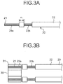
- FIG. 3A to FIG. 3C are diagrams illustrating the manufacturing process of the electronic circuit module 100 according to the first embodiment of the present invention.
- Step S1 the external insulator 22 of the solid wire cable 20 is removed, and the core 21 is exposed.
- the removal of the external insulator 22 is performed to set the first conductor portion 23a and the second conductor portion 23b to be a predetermined length.
- Step S2 After the external insulator 22 is removed (Step S1), the solid wire cable 20 and the electronic component 30 are connected to each other (Step S2). As illustrated in FIG. 3B , the first conductor portion 23a is positioned on the terminal 31 of the electronic component 30 covered with the solder, and the solder is melted by heating, and thus, the solid wire cable 20 and the electronic component 30 are connected to each other.
- Step S3 the solid wire cable 20 is connected to the electrode portion 11 (Step S3).
- the second conductor portion 23b is positioned on the electrode portion 11 of the substrate 10 covered with the solder, and the solder is melted by heating, and thus, the solid wire cable 20 and the electrode portion 11 are connected to each other.
- a conductive member such as ACP or ACF is also capable of being used as a member used for the connection, in addition to the solder.
- solder having a high melting point rather than the solder used in Step S2 may be used.
- the electronic circuit module 100 according to the first embodiment is capable of reducing the area required for mounting the solid wire cable 20 and the electronic component 30 onto the substrate 10, it is possible to provide the downsized electronic circuit module 100.
- FIG. 4A is a side view of an electronic circuit module according to a first modification of the first embodiment of the present invention.
- FIG. 4B is a top view of the electronic circuit module according to the first modification of the first embodiment of the present invention.
- an electronic component 33 is mounted on a connection electrode 12 on a substrate 10A, in addition to the solid wire cable 20 and the electronic component 30.
- the solid wire cable 20 is bent in the external insulator 22 between the first conductor portion 23a and the second conductor portion 23b at approximately a right angle. Accordingly, it is possible to mount the electronic component 30 and the electronic component 33 on the substrate 10 without interfering with each other.
- FIG. 5A is a side view of an electronic circuit module according to a second modification of the first embodiment of the present invention.
- FIG. 5B is a top view of the electronic circuit module according to second modification of the first embodiment of the present invention.
- a prism 34 is mounted on a substrate 10B, in addition to the solid wire cable 20 and the electronic component 30.
- the solid wire cable 20 is bent in the external insulator 22 between the first conductor portion 23a and the second conductor portion 23b along a back side 34a of the prism 34. Accordingly, it is possible to mount the electronic component 30 and the prism 34 on the substrate 10 without interfering with each other.
- FIG. 6 is a side view of an electronic circuit module according to a third modification of the first embodiment of the present invention.
- An electronic circuit module 100C according to the third modification of the first embodiment of the present invention is different from the first embodiment in that the first conductor portion 23a is connected to the electrode portion 11, and the electronic component 30 is connected to the second conductor portion 23b.
- the electronic circuit module 100C it is possible to reduce the area required for mounting the solid wire cable 20 and the electronic component 30 onto a substrate 10C, and thus, it is possible to provide the downsized electronic circuit module 100C.
- FIG. 7 is a side view of an electronic circuit module according to a fourth modification of the first embodiment of the present invention.
- a substrate 10D does not extend under the second conductor portion 23b to which the electronic component 30 is connected.
- the substrate 10D may be disposed in a lower portion of the external insulator 22 in which an end portion on the solid wire cable 20 side insulates at least the first conductor portion 23a and the second conductor portion 23b.
- the electronic circuit module 100D according to the fourth modification of the first embodiment it is possible to reduce the area required for mounting the solid wire cable 20 and the electronic component 30 onto the substrate 10D, and thus, it is possible to provide the downsized electronic circuit module 100D.
- FIG. 8 is a side view of an electronic circuit module according to a fifth modification of the first embodiment of the present invention.
- a substrate 10E does not extend under the second conductor portion 23b to which the electronic component 30 is connected, and the electronic component 30 is connected to the lower portion of the second conductor portion 23b.
- the electronic circuit module 100E according to the fifth modification of the first embodiment it is possible to reduce the area required for mounting the solid wire cable 20 and the electronic component 30 onto the substrate 10E, and thus, it is possible to provide the downsized electronic circuit module 100E.
- the electronic component 30 is connected to the lower portion of the second conductor portion 23b, and the electronic component 30 suspended from the second conductor portion 23b is inserted into an opening on the substrate which extends under the second conductor portion 23b.
- FIG. 9 is a top view of an electronic circuit module according to a sixth modification of the first embodiment of the present invention.
- Three electrode portions 11 respectively connecting three solid wire cables 20 are disposed on a substrate 10K of an electronic circuit module 100K.
- the solid wire cable 20 is connected to the electrode portion 11 at the second electrode portion 23b.
- An electronic component 30K includes a ground terminal 31a between the terminals 31, in addition to the terminals 31 on the opposed faces.
- An electronic component 30K is connected onto the first conductor portion 23a of three solid wire cables 20 by positioning the terminals 31 and 31a.
- the electrode portion 11 is connected to the second conductor portion 23b, and the electronic component 30K is connected to the first conductor portion 23a.
- the first conductor portion 23a may be connected to the electrode portion 11, and the electronic component 30K may be connected onto the second conductor portion 23b.
- FIG. 10A is a side view of the electronic circuit module according to the second embodiment of the present invention.
- FIG. 10B is a top view of the electronic circuit module according to the second embodiment of the present invention.
- a conductor portion 23 is formed in which only the external insulator 22 in the end portion of the solid wire cable 20 is removed, and thus, the core 21 is exposed.
- the conductor portion 23 is connected to the electrode portion 11 of a substrate 10F by solder, and the electronic component 30 is directly connected onto the conductor portion 23 which is connected to the electrode portion 11 by solder.
- the length r3 of the conductor portion 23 is a length which is approximately identical to the length r2 of the terminal 31 of the electronic component 30, and the conductor portion 23 is connected to the electrode portion 11 to be in contact with the entire length of the terminal 31 of the electronic component 30 in the lengthwise direction.
- the conductor portion 23 may have a length which is longer than at least a length r4 of the electrode portion 11, and may be connected to the electrode portion 11 over a half of the length r2 of the terminal 31. From the viewpoint of the connection reliability, it is preferable that the conductor portion 23 is connected to the electrode portion 11 to be greater than or equal to 80% of the length r2 of the terminal 31.
- An end portion of the conductor portion 23 is located and adjusted not to protrude to the front side from the electronic component 30 (in FIG. 10B and FIG. 10B , a left side).
- the length r3 of the conductor portion 23 is greater than or equal to the length r4 of the electrode portion 11, is greater than or equal to 50% of the length r2 of the terminal 31, and is preferably greater than or equal to 80%.
- the electronic circuit module 100F it is possible to reduce the area required for mounting the solid wire cable 20 and the electronic component 30 onto the substrate 10F, and thus, it is possible to provide the downsized electronic circuit module 100F. Since only the external insulator 22 in the end portion of the solid wire cable 20 is removed, the manufacturing is further simplified.
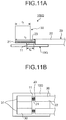
- FIG. 11A is a side view of an electronic circuit module according to a first modification of the second embodiment of the present invention.
- FIG. 11B is a top view of the electronic circuit module according to the first modification of the second embodiment of the present invention.
- the length r3 of the conductor portion 23 is longer than the length r2 of the terminal 31 of the electronic component 30.
- the end portion of the conductor portion 23 does not protrude to the front side from the electronic component 30 (in FIG. 11B and FIG. 11B , a left side).
- FIG. 11B it is possible to view the end portion of the electrode portion 11 from an upper side, and thus, it is possible to easily position the solid wire cable 20 to which the electronic component 30 is connected and the electrode portion 11.
- FIG. 12A is a side view of an electronic circuit module according to a second modification of the second embodiment of the present invention.
- FIG. 12B is a top view of the electronic circuit module according to the second modification of the second embodiment of the present invention.
- FIG. 13 is a top view of a substrate to be used in the electronic circuit module of FIG. 12A and FIG. 12B .
- a flexible printed circuit board is used as a substrate 10H.
- an opening 13 is formed on the substrate 10H, and an electrode portion 11H as flying leads bridges the opening 13.
- the electrode portion 11H it is possible to connect the electronic component 30 and the electrode portion 11H by positioning the electronic component 30 and the electrode portion 11H from a lower side (in FIG. 12A , a lower side) through the opening 13, at the time of connecting the conductor portion 23 to which the electronic component 30.
- FIG. 14A is a side view of an electronic circuit module according to a third modification of the second embodiment of the present invention.
- FIG. 14B is a top view of an electronic circuit module according to a fourth modification of the second embodiment of the present invention.
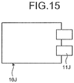
- FIG. 15 is a top view of a substrate to be used in the electronic circuit module of FIG. 14A and FIG. 14B .
- a flexible printed circuit board is used as a substrate 10J, and as illustrated in FIG. 15 , an electrode portion 11J as flying leads is formed to extend from an end portion of the substrate 10J.
- the electrode portion 11J it is possible to connect the electronic component 30 and the electrode portion 11J by positioning the electronic component 30 and the electrode portion 11J from the lower side (in FIG. 14A , a lower side), at the time of connecting the conductor portion 23 to which the electronic component 30 is connected.
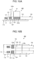
- FIG. 16A is a side view of the electronic circuit module according to the third embodiment of the present invention.
- FIG. 16B is a top view of the electronic circuit module according to the third embodiment of the present invention.
- a coaxial cable 120 is used as the cable.
- a shield line 123 is formed on an outer circumference of a core 121 through an internal insulator 122, an outer circumference of the shield line 123 is covered with an external insulator 124.
- the core 121, the internal insulator 122, and the shield line 123 are exposed in a stepwise fashion.
- the external insulator 124 on the outer circumference of the shield line 123 is removed in two portions to form two exposed portions of the shield line 123.
- a distal end side of the two exposed portions of the shield line is a first conductor portion 125a, and a base end side of the two exposed portions is a second conductor portion 125b.
- An electrode portion 111 connecting the core 121 and an electrode portion 112 connecting the shield line 123 are formed on the substrate 110.
- the core 121 and the first conductor portion 125a are respectively connected to the electrode portion 111 and the electrode portion 112 by solder, and an electronic component 130 is connected onto the second conductor portion 125b.
- the electronic component 130 includes terminals 131 on opposed faces, and the terminal 131 is connected to the second conductor portion 125b.
- the electronic circuit module 200 it is possible to reduce the area required for mounting the cable 120 and the electronic component 130 onto the substrate 110, and thus, it is possible to provide the downsized electronic circuit module 200.
- FIG. 17 is a side view of an electronic circuit module according to a first modification of the third embodiment of the present invention.
- the core 121, the internal insulator 122, and the shield line 123 are exposed in a stepwise fashion in the end portion of the coaxial cable 120.
- the exposed portion of the shield line 123 functions as a conductor portion 125.
- the conductor portion 125 is connected to the electrode portion 112, and the electronic component 130 is connected onto the conductor portion 125.
- the electronic circuit module 200A it is possible to reduce the area required for mounting the cable 120 and the electronic component 130 onto the substrate 110, and thus, it is possible to provide the downsized electronic circuit module 200A.
- a connection portion such as the external insulator 124 of the cable 120 is small, and thus, it is possible to easily manufacture the electronic circuit module.
- FIG. 18A is a side view of an electronic circuit module according to a second modification of the third embodiment of the present invention.
- FIG. 18B is a top view of the electronic circuit module according to the second modification of the third embodiment of the present invention.
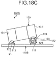
- FIG. 18C is a front view of the electronic circuit module according to the second modification of the third embodiment of the present invention.
- the solid wire cable 20 and the coaxial cable 120 are used.
- the external insulator 124 is removed such that the core 121, the internal insulator 122, and the shield line 123 are exposed in a stepwise fashion.
- the external insulator 124 on the outer circumference of the shield line 123 is removed in two portions to expose the shield line 123 at the first conductor portion 125a on the distal end side and at the second conductor portion 125b on the base end side from the first conductor portion 125a.
- the external insulator 22 is removed in two portions to expose the core 21 at the first conductor portion 23a on the distal end side and at the second conductor portion 23b on the base end side from the first conductor portion 23a.
- the electrode portion 111 connecting the core 121 of the coaxial cable 120, the electrode portion 112 connecting the shield line 123, and an electrode portion 113 connecting the core 21 of the solid wire cable 20 are formed on a substrate 110B.
- the core 121 and the first conductor portion 125a of the coaxial cable 120 are respectively connected to the electrode portion 111 and the electrode portion 112 by solder, and the first conductor portion 23a of the solid wire cable 20 is connected to the electrode portion 113 by solder.
- One of the opposed terminals 131 of the electronic component 130 is connected to the second conductor portion 125b of the coaxial cable 120, and the other of the terminals 131 is connected to the second conductor portion 23b of the solid wire cable 20.
- the electronic circuit module 200B according to the second modification of the third embodiment, it is possible to reduce the area required for mounting the solid wire cable 20, the coaxial cable 120, and the electronic component 130 onto the substrate 110B, and thus, it is possible to provide the downsized electronic circuit module 200B.
- Each of the shield line 123 of the coaxial cable 120 and the core 21 of the solid wire cable 20 is exposed at only one portion to define the conductor portion.
- the core 121 and the shield line 123 as the conductor portion of the coaxial cable 120 are respectively connected to the electrode portion 111 and the electrode portion 112, and the core 21 as the conductor portion of the solid wire cable 20 is connected to the electrode portion 131.
- One of the opposed terminals 131 of the electronic component 130 may be connected to the conductor portion of the coaxial cable 120, and the other of the terminals 131 may be connected to the conductor portion of the solid wire cable 20.
- FIG. 19A is a side view of the electronic circuit module according to the fourth embodiment of the present invention.
- FIG. 19B is a top view of the electronic circuit module according to the fourth embodiment of the present invention.
- FIG. 19C is a front view of the electronic circuit module according to the fourth embodiment of the present invention.
- An electronic circuit module 300 includes one solid wire cable 20 whose external insulator 22 at the end portion is removed to expose the core 21, the electronic component 130 including the terminals 131 on the opposed faces, one electrode portion 211 to which the solid wire cable 20 is connected, and a substrate 210 including one connection electrode 212 to which the electronic component 130 is connected.
- the electronic circuit module 300 includes the first conductor portion 23a where the core 21 is exposed on the distal end side, and the second conductor portion 23b where the core 21 is exposed on the base end side from the first conductor portion 23a.
- the second conductor portion 23b is connected to the electrode portion 211 by solder.
- the terminals 131 of the electronic component 130 are respectively connected to the connection electrode 212 and the first conductor portion 23a.
- the electronic circuit module 300 it is possible to reduce the area required for mounting the solid wire cable 20 and the electronic component 130 onto the substrate 210, and thus, it is possible to provide the downsized electronic circuit module 300.
- the core 21 of the solid wire cable 20 may be exposed in only one portion to form a conductor portion.
- the core 21 may be connected to the electrode portion 211, one of the opposed terminals 131 of the electronic component 130 may be directly connected to the upper portion of the core 21, and the other of the terminals 131 may be connected to the connection electrode 212.
- FIG. 20 is a side view of the electronic circuit module according to the fifth embodiment of the present invention.
- An electronic circuit module 300A includes the coaxial cable 120 in which the core 121, the internal insulator 122, and the shield line 123 are exposed in a stepwise fashion, the electronic component 130 including the terminals 131 on the opposed faces, and a substrate 210A on which the electrode portions 211 and 213 are formed.
- the core 121 and the shield line 123 are respectively connected to the electrode portions 211 and 213.
- the exposed portions of the core 121 and the shield line 123 function as a conductor portion.
- the core 121 is connected to the electrode portion 211 by solder, and the shield line 123 is connected to the electrode portion 213 by solder.
- the electronic component 130 is directly connected onto the core 121 in which one of the terminals 131 is connected to the electrode portion 211, by solder, and is directly connected onto the shield line 123 in which the other terminal 131 is connected to the electrode portion 213, by solder.
- the electronic circuit module 300A it is possible to reduce the area required for mounting the coaxial cable 120 and the electronic component 130 onto the substrate 210A, and thus, it is possible to provide the downsized electronic circuit module 300A.
- the electronic component 130 is connected to the coaxial cable 120 on an upper side, that is, the coaxial cable 120 on a side opposite to the substrate 210A, and may be connected to the coaxial cable 120 on the side.
- FIG. 21A is a side view of an electronic circuit module according to a first modification of the fifth embodiment of the present invention.
- FIG. 21B is a top view of the electronic circuit module according to the first modification of the fifth embodiment of the present invention.
- FIG. 21C is a front view of the electronic circuit module according to the first modification of the fifth embodiment of the present invention.
- the core 121 is connected to an electrode portion 211B by solder, and the shield line 123 is connected to an electrode portion 213B by solder.
- the electronic component 130 is located on the side of a substrate 210B and the coaxial cable 120, and one of the terminals 131 is directly connected to the electrode portion 211B and the core 121 by solder, and the other terminal 131 is directly connected to the electrode portion 213B and the shield line 123 by solder.
- the electronic circuit module 300B according to the first modification of the fifth embodiment, it is possible to reduce the area required for mounting the coaxial cable 120 and the electronic component 130 onto the substrate 210B, and thus, it is possible to achieve the downsized electronic circuit module 300B.
- the electronic circuit module of the present invention is particularly suitable for an application which requires downsizing.
Landscapes
- Engineering & Computer Science (AREA)
- Microelectronics & Electronic Packaging (AREA)
- Structures For Mounting Electric Components On Printed Circuit Boards (AREA)
- Insertion, Bundling And Securing Of Wires For Electric Apparatuses (AREA)
- Multi-Conductor Connections (AREA)
- Coupling Device And Connection With Printed Circuit (AREA)
Abstract
An electronic circuit module (100F) includes a substrate (10) on which a wiring pattern having an electrode portion (11) is formed; a cable (20) having an external insulator, at least a distal end side of the external insulator being removed to expose a conductor (23), an exposed portion of the conductor (23) being defined as a conductor portion (23), the cable (20) being connected to the electrode portion (11) through the conductor portion (23); and an electronic component (30) having terminals at least on opposed faces. The terminals of the electronic component (30) are directly connected to the conductor portion (23).
Description
- The present invention relates to an electronic circuit module.
- Recently, various electronic devices, such as a digital camera, a mobile phone have been downsized. In the digital camera, the mobile phone, and the like, in order to improve portability, a cooling effect with respect to heat, or the like, a housing and an electronic circuit module contained in the housing have been downsized. Endoscopes configured to be inserted into a subject for observation have an electronic circuit module including an image sensor mounted on a tip end portion of an elongated flexible insertion tool. In such an endoscope, the diameter and the length of the tip end portion of the insertion tool is required to be reduced in order to reduce the burden on a patient, and there is a high demand for downsizing the electronic circuit module.
- As a technology for providing the downsized electronic circuit modules, an electronic circuit module in which a core and a shield line of a coaxial cable is directly connected to a terminal of an electronic component on a substrate is disclosed (for example, refer to Patent Literature 1).
- Patent Literature 1:
JP 2011-119409 A - Although it is possible to reduce an area required for cable connection of the electronic circuit module of Patent Literature 1 and achieve the downsized module, the electronic circuit module is required to be further downsized.
- The applicant has focused on the fact that the area required for the cable connection on the substrate is smaller than an area required for the mounting of the electronic component, and has found that it is possible to further downsize the electronic circuit module by connecting the electronic component to a conductor portion of a cable connected onto the substrate.
- The present invention has been made in view of the foregoing, an object of the invention is to provide a downsized electronic circuit module.
- In order to solve the above described problem and achieve the object, an electronic circuit module according to the invention includes: a substrate on which a wiring pattern having an electrode portion is formed; a cable having an external insulator, at least a distal end side of the external insulator being removed to expose a conductor, an exposed portion of the conductor being defined as a conductor portion, the cable being connected to the electrode portion through the conductor portion; and an electronic component having terminals at least on opposed faces of the electronic component. The terminals of the electronic component are directly connected to the conductor portion.
- In the electronic circuit module according to the invention, the cable includes at least two solid wire cables, each of which has the external insulator removed on the distal end side to expose a core. An exposed portion of the core is defined as the conductor portion. The conductor portion is connected to the electrode portion. The electronic component is directly connected to one side of the conductor portion through each of the terminals, an opposite side of the conductor portion being in contact with the electrode portion.
- In the electronic circuit module according to the invention, the cable includes at least two solid wire cables, each of which has the external insulator that is removed on the distal end side to define an exposed portion of a core as a first conductor portion and is removed on a base end side from the first conductor portion to define another exposed portion of the core as a second conductor portion. The second conductor portion is connected to the electrode portion. The electronic component is directly connected to the first conductor portion through each of the terminals.
- The electronic circuit module according to the invention further includes an optical component or another electronic component on the substrate. The cable is bent between the first conductor portion and the second conductor portion along a back side of the optical component or another electronic component.
- In the electronic circuit module according to the invention, the cable includes at least two solid wire cables, each of which has the external insulator that is removed on the distal end side to define an exposed portion of a core as a first conductor portion and is removed on a base end side from the first conductor portion to define another exposed portion of the core as a second conductor portion. The first conductor portion is connected to the electrode portion. The electronic component is directly connected to the second conductor portion through each of the terminals.
- In the electronic circuit module according to the invention, the substrate is a flexible printed circuit board having an opening. The electrode portion includes flying leads bridging the opening. The conductor portion is connected to the electrode portion.
- In the electronic circuit module according to the invention, the substrate is a flexible printed circuit board having the electrode portion including flying leads extending from an end portion of the flexible printed circuit board. The conductor portion is connected to the electrode portion.
- In the electronic circuit module according to the invention, the cable includes one coaxial cable having a core and a shield line. The core and the shield line are exposed in a stepwise fashion from an end portion of the coaxial cable. Exposed portions of the core and the shield line constitute the conductor portion, and are connected to the electrode portion on the substrate. Each of the terminals of the electronic component is directly connected to the conductor portion.
- In the electronic circuit module according to the invention, the cable includes at least two coaxial cables, each of which has a core and a shield line. The core and the shield line are exposed in a stepwise fashion from an end portion of each coaxial cable. Exposed portions of the core and the shield line are connected to the electrode portion on the substrate. An exposed portion of the shield line is defined as the conductor portion. Each of the terminals of the electronic component is directly connected to the conductor portion.
- In the electronic circuit module according to the invention, each of the at least two coaxial cable has the external insulator that is removed on the distal end side to define the exposed portion of the shield line as a first conductor portion and is removed on a base end side from the first conductor portion to define another exposed portion of the shield line as a second conductor portion. The first conductor portion is connected to the electrode portion. The electronic component is directly connected to the second conductor portion through each of the terminals.
- In the electronic circuit module according to the invention, the cable includes at least: a solid wire cable having the external insulator removed on the at least the distal end side to expose a core; and a coaxial cable having a core and a shield line, at least the core and the shield line being exposed in a stepwise fashion from an end portion of the coaxial cable. The core of the solid wire cable, and the core and the shield line of the coaxial cable are connected to the electrode portion on the substrate. An exposed portion of the core of the solid wire cable is defined as the conductor portion. An exposed portion of the shield line of the coaxial cable is defined as an additional conductor portion. The terminals of the electronic component are directly connected to the conductor portion and the additional conductor portion, respectively.
- In the electronic circuit module according to the invention, the cable includes one solid wire cable having the external insulator removed on the distal end side to expose a core. An exposed portion of the core is defined as the conductor portion. The substrate has the electrode portion connected to the conductor portion and has a connection electrode. One of the terminals of the electronic component is connected to the connection electrode on the substrate, and the other of the terminals is directly connected onto the conductor portion. Advantageous Effects of Invention
- An electronic circuit module of the present invention has a small area required for connecting a cable and an electronic component to a substrate, which makes it possible to achieve a downsized electronic circuit module.
-
-
FIG. 1A is a side view of an electronic circuit module according to a first embodiment of the present invention. -
FIG. 1B is a top view of the electronic circuit module according to the first embodiment of the present invention. -
FIG. 2 is a flowchart illustrating a manufacturing process of the electronic circuit module according to the first embodiment of the present invention. -
FIG. 3A is a diagram illustrating the manufacturing process of the electronic circuit module according to the first embodiment of the present invention. -
FIG. 3B is a diagram illustrating the manufacturing process of the electronic circuit module according to the first embodiment of the present invention. -
FIG. 3C is a diagram illustrating the manufacturing process of the electronic circuit module according to the first embodiment of the present invention. -
FIG. 4A is a side view of an electronic circuit module according to a first modification of the first embodiment of the present invention. -
FIG. 4B is a top view of the electronic circuit module according to the first modification of the first embodiment of the present invention. -
FIG. 5A is a side view of an electronic circuit module according to a second modification of the first embodiment of the present invention. -
FIG. 5B is a top view of the electronic circuit module according to the second modification of the first embodiment of the present invention. -
FIG. 6 is a side view of an electronic circuit module according to a third modification of the first embodiment of the present invention. -
FIG. 7 is a side view of an electronic circuit module according to a fourth modification of the first embodiment of the present invention. -
FIG. 8 is a side view of an electronic circuit module according to a fifth modification of the first embodiment of the present invention. -
FIG. 9 is a top view of an electronic circuit module according to a sixth modification of the first embodiment of the present invention. -
FIG. 10A is a side view of an electronic circuit module according to a second embodiment of the present invention. -
FIG. 10B is a top view of the electronic circuit module according to the second embodiment of the present invention. -
FIG. 11A is a side view of an electronic circuit module according to a first modification of the second embodiment of the present invention. -
FIG. 11B is a top view of the electronic circuit module according to the first modification of the second embodiment of the present invention. -
FIG. 12A is a side view of an electronic circuit module according to a second modification of the second embodiment of the present invention. -
FIG. 12B is a top view of the electronic circuit module according to the second modification of the second embodiment of the present invention. -
FIG. 13 is a top view of a substrate to be used in the electronic circuit module ofFIG. 12A and FIG. 12B . -
FIG. 14A is a side view of an electronic circuit module according to a third modification of the second embodiment of the present invention. -
FIG. 14B is a top view of the electronic circuit module according to the third modification of the second embodiment of the present invention. -
FIG. 15 is a top view of a substrate to be used in the electronic circuit module ofFIG. 14A and FIG. 14B . -
FIG. 16A is a side view of an electronic circuit module according to a third embodiment of the present invention. -
FIG. 16B is a top view of the electronic circuit module according to the third embodiment of the present invention. -
FIG. 17 is a side view of an electronic circuit module according to a first modification of the third embodiment of the present invention. -
FIG. 18A is a side view of an electronic circuit module according to a second modification of the third embodiment of the present invention. -
FIG. 18B is a top view of the electronic circuit module according to the second modification of the third embodiment of the present invention. -
FIG. 18C is a front view of the electronic circuit module according to the second modification of the third embodiment of the present invention. -
FIG. 19A is a side view of an electronic circuit module according to a fourth embodiment of the present invention. -
FIG. 19B is a top view of the electronic circuit module according to the fourth embodiment of the present invention. -
FIG. 19C is a front view of the electronic circuit module according to the fourth embodiment of the present invention. -
FIG. 20 is a side view of an electronic circuit module according to a fifth embodiment of the present invention. -
FIG. 21A is a side view of an electronic circuit module according to a first modification of the fifth embodiment of the present invention. -
FIG. 21B is a top view of the electronic circuit module according to the first modification of the fifth embodiment of the present invention. -
FIG. 21C is a front view of the electronic circuit module according to the first modification of the fifth embodiment of the present invention. - Hereinafter, modes for carrying out the present invention (hereinafter, referred to as "embodiment(s)") will be described with reference to the attached drawings. The present invention is not limited by the embodiments. The same reference signs are used to designate the same elements throughout the drawings. The drawings are schematically illustrated, and a relationship between a thickness and a width of each member, a proportion of each of the members, and the like may be different from the reality. In the drawings, there are portions whose dimensional relationships or proportions are different from one another.
-
FIG. 1A is a side view of an electronic circuit module according to a first embodiment of the present invention.FIG. 1B is a top view of the electronic circuit module according to the first embodiment of the present invention. Anelectronic circuit module 100 according to the first embodiment of the present invention includes asubstrate 10 on which a wiring pattern having anelectrode portion 11 is formed, twosolid wire cables 20, each of which includes anexternal insulator 22 having two portions removed to expose acore 21, and anelectronic component 30 having terminals on opposed faces. The removal of the insulator is performed, for example, by using laser processing, but is not limited thereto. The insulator may be removed or peeled off by etching or machine processing using a blade such as a cutter. - The
substrate 10 has a plate shape. As thesubstrate 10, a flexible printed circuit board, a ceramic substrate, a glass epoxy substrate, a glass substrate, a silicon substrate, or the like is employed. Twoelectrode portions 11 to which thesolid wire cables 20 are connected are arranged on thesubstrate 10. The wiring pattern is formed on the surface of thesubstrate 10 on which theelectrode portions 11 are arranged, but is not illustrated. - The
solid wire cable 20 includes thecore 21 and theexternal insulator 22 covering thecore 21. In thesolid wire cable 20, theexternal insulator 22 is removed in two portions to expose thecore 21. One of the exposed portions of the core 21 on a distal end side is afirst conductor portion 23a, and the other of the exposed portions of the core 21 on a base end side from thefirst conductor portion 23a is asecond conductor portion 23b. It is preferable that a length r1 of theexternal insulator 22 between thefirst conductor portion 23a and thesecond conductor portion 23b is approximately 0.05 mm. InFIGS. 1A and 1B , solder connecting theelectrode portion 11 to thesecond conductor portion 23b and connecting theelectronic component 30 described below to thefirst conductor portion 23a is not illustrated. - In the
electronic circuit module 100, thesecond conductor portion 23b on the base end side is connected to theelectrode portion 11 by solder, and theelectronic component 30 is connected onto thefirst conductor portion 23a on the distal end side. Thefirst conductor portion 23a is connected to a terminal 31 formed on an end surface of the electronic component by solder. A length r3 of thefirst conductor portion 23a is a length which is approximately identical to a length r2 of the terminal 31 of theelectronic component 30, and thefirst conductor portion 23a is connected to the terminal 31 to be in contact with the entire length of the terminal 31 of theelectronic component 30 in a lengthwise direction. It is possible to hold theelectronic component 30 insofar as thefirst conductor portion 23a is connected to the terminal 31 at least over approximately a half of the length r2 of the terminal 31. From the viewpoint of connection reliability, it is preferable that thefirst conductor portion 23a is connected to the terminal 31 to be greater than or equal to 80% of the length r2 of the terminal 31. It is preferable that an end portion of thefirst conductor portion 23a does not protrude to a front side from the electronic component 30 (a left side inFIGS. 1B and 1B ). From the viewpoint described above, the length r3 of thefirst conductor portion 23a is greater than or equal to 50% of the length r2 of the terminal 31, and is preferably greater than or equal to 80%. - An area A2 required for the connection of the
solid wire cable 20 is illustrated inFIG. 1B , and is less than an area, which is represented by A1, required for the mounting of theelectronic component 30. Theelectronic component 30 is connected to thefirst conductor portion 23a exposed to the end portion, and thus, theelectronic component 30 mounted on thesubstrate 10 is connected to thesolid wire cable 20, and therefore, it is possible to reduce the area required for the mounting by (A1 - A2). As represented by A1 inFIG. 1B , a wiring pattern is arranged on thesubstrate 10 under thefirst conductor portion 23a to which theelectronic component 30 is connected. - Next, a manufacturing method of the
electronic circuit module 100 will be described with reference toFIG. 2 , andFIG. 3A toFIG. 3C .FIG. 2 is a flowchart illustrating a manufacturing process of theelectronic circuit module 100 according to the first embodiment of the present invention.FIG. 3A to FIG. 3C are diagrams illustrating the manufacturing process of theelectronic circuit module 100 according to the first embodiment of the present invention. - First, as illustrated in
FIG. 3A , theexternal insulator 22 of thesolid wire cable 20 is removed, and thecore 21 is exposed (Step S1). The removal of theexternal insulator 22 is performed to set thefirst conductor portion 23a and thesecond conductor portion 23b to be a predetermined length. - After the
external insulator 22 is removed (Step S1), thesolid wire cable 20 and theelectronic component 30 are connected to each other (Step S2). As illustrated inFIG. 3B , thefirst conductor portion 23a is positioned on theterminal 31 of theelectronic component 30 covered with the solder, and the solder is melted by heating, and thus, thesolid wire cable 20 and theelectronic component 30 are connected to each other. - After the
solid wire cable 20 and theelectronic component 30 are connected to each other (Step S2), thesolid wire cable 20 is connected to the electrode portion 11 (Step S3). As illustrated inFIG. 3C , thesecond conductor portion 23b is positioned on theelectrode portion 11 of thesubstrate 10 covered with the solder, and the solder is melted by heating, and thus, thesolid wire cable 20 and theelectrode portion 11 are connected to each other. At this time, for example, a conductive member such as ACP or ACF is also capable of being used as a member used for the connection, in addition to the solder. Alternatively, solder having a high melting point rather than the solder used in Step S2 may be used. - Since the
electronic circuit module 100 according to the first embodiment is capable of reducing the area required for mounting thesolid wire cable 20 and theelectronic component 30 onto thesubstrate 10, it is possible to provide the downsizedelectronic circuit module 100. - In the
electronic circuit module 100 according to the first embodiment, the wiring pattern is formed on thesubstrate 10 under thefirst conductor portion 23a to which theelectronic component 30 is connected, and other components or the like may be mounted.FIG. 4A is a side view of an electronic circuit module according to a first modification of the first embodiment of the present invention.FIG. 4B is a top view of the electronic circuit module according to the first modification of the first embodiment of the present invention. - In an
electronic circuit module 100A according to the first modification of the first embodiment of the present invention, anelectronic component 33 is mounted on aconnection electrode 12 on asubstrate 10A, in addition to thesolid wire cable 20 and theelectronic component 30. Thesolid wire cable 20 is bent in theexternal insulator 22 between thefirst conductor portion 23a and thesecond conductor portion 23b at approximately a right angle. Accordingly, it is possible to mount theelectronic component 30 and theelectronic component 33 on thesubstrate 10 without interfering with each other. In theelectronic circuit module 100A according to the first modification of the first embodiment of the present invention, it is possible to reduce the area required for mounting thesolid wire cable 20 and theelectronic component 30 onto thesubstrate 10A, and thus, it is possible to provide the downsizedelectronic circuit module 100A. - On the substrate, an optical component such as a prism may be mounted.
FIG. 5A is a side view of an electronic circuit module according to a second modification of the first embodiment of the present invention.FIG. 5B is a top view of the electronic circuit module according to second modification of the first embodiment of the present invention. - In an
electronic circuit module 100B according to the second modification of the first embodiment of the present invention, aprism 34 is mounted on asubstrate 10B, in addition to thesolid wire cable 20 and theelectronic component 30. Thesolid wire cable 20 is bent in theexternal insulator 22 between thefirst conductor portion 23a and thesecond conductor portion 23b along aback side 34a of theprism 34. Accordingly, it is possible to mount theelectronic component 30 and theprism 34 on thesubstrate 10 without interfering with each other. In theelectronic circuit module 100B according to the second modification of the first embodiment of the present invention, it is possible to reduce the area required for mounting thesolid wire cable 20 and theelectronic component 30 onto thesubstrate 10B, and thus, it is possible to provide the downsizedelectronic circuit module 100B. - The
electronic component 30 may be connected to thesecond conductor portion 23b, which is an exposed portion of the core 21 on the base end side.FIG. 6 is a side view of an electronic circuit module according to a third modification of the first embodiment of the present invention. Anelectronic circuit module 100C according to the third modification of the first embodiment of the present invention is different from the first embodiment in that thefirst conductor portion 23a is connected to theelectrode portion 11, and theelectronic component 30 is connected to thesecond conductor portion 23b. - In the
electronic circuit module 100C according to the third modification of the first embodiment, it is possible to reduce the area required for mounting thesolid wire cable 20 and theelectronic component 30 onto asubstrate 10C, and thus, it is possible to provide the downsizedelectronic circuit module 100C. - In the
electronic circuit module 100C according to the third modification of the first embodiment, thesubstrate 10C extends, and thesolid wire cable 20 is supported, under thesecond conductor portion 23b to which theelectronic component 30 is connected, but it is not necessary that the substrate is disposed under thesecond conductor portion 23b to which theelectronic component 30 is connected.FIG. 7 is a side view of an electronic circuit module according to a fourth modification of the first embodiment of the present invention. In anelectronic circuit module 100D according to the fourth modification of first embodiment, asubstrate 10D does not extend under thesecond conductor portion 23b to which theelectronic component 30 is connected. Thesubstrate 10D may be disposed in a lower portion of theexternal insulator 22 in which an end portion on thesolid wire cable 20 side insulates at least thefirst conductor portion 23a and thesecond conductor portion 23b. In theelectronic circuit module 100D according to the fourth modification of the first embodiment, it is possible to reduce the area required for mounting thesolid wire cable 20 and theelectronic component 30 onto thesubstrate 10D, and thus, it is possible to provide the downsizedelectronic circuit module 100D. - The
electronic component 30 may be connected to a lower portion of thesecond conductor portion 23b.FIG. 8 is a side view of an electronic circuit module according to a fifth modification of the first embodiment of the present invention. As with the fourth modification, in anelectronic circuit module 100E according to the fifth modification of the first embodiment, asubstrate 10E does not extend under thesecond conductor portion 23b to which theelectronic component 30 is connected, and theelectronic component 30 is connected to the lower portion of thesecond conductor portion 23b. In theelectronic circuit module 100E according to the fifth modification of the first embodiment, it is possible to reduce the area required for mounting thesolid wire cable 20 and theelectronic component 30 onto thesubstrate 10E, and thus, it is possible to provide the downsizedelectronic circuit module 100E. Theelectronic component 30 is connected to the lower portion of thesecond conductor portion 23b, and theelectronic component 30 suspended from thesecond conductor portion 23b is inserted into an opening on the substrate which extends under thesecond conductor portion 23b. - In the first embodiment described above and the first modification to the fifth modification of the first embodiment, the
terminals 31 on the opposed faces of theelectronic component 30 are respectively connected onto thecores 21 of the twosolid wire cables 20, and the electronic component may be connected onto thecores 21 of threesolid wire cables 20.FIG. 9 is a top view of an electronic circuit module according to a sixth modification of the first embodiment of the present invention. - Three
electrode portions 11 respectively connecting threesolid wire cables 20 are disposed on asubstrate 10K of anelectronic circuit module 100K. Thesolid wire cable 20 is connected to theelectrode portion 11 at thesecond electrode portion 23b. Anelectronic component 30K includes aground terminal 31a between theterminals 31, in addition to theterminals 31 on the opposed faces. Anelectronic component 30K is connected onto thefirst conductor portion 23a of threesolid wire cables 20 by positioning theterminals electronic circuit module 100K according to the sixth modification of the first embodiment, it is possible to reduce the area required for mounting thesolid wire cable 20 and theelectronic component 30K onto thesubstrate 10K, and thus, it is possible to provide the downsizedelectronic circuit module 100K. In the sixth modification of the first embodiment, theelectrode portion 11 is connected to thesecond conductor portion 23b, and theelectronic component 30K is connected to thefirst conductor portion 23a. Alternatively, thefirst conductor portion 23a may be connected to theelectrode portion 11, and theelectronic component 30K may be connected onto thesecond conductor portion 23b. - In an electronic circuit module according to a second embodiment of the present invention, a conductor portion is formed in which only the
external insulator 22 in the end portion of thesolid wire cable 20 is removed, and thus, thecore 21 is exposed.FIG. 10A is a side view of the electronic circuit module according to the second embodiment of the present invention.FIG. 10B is a top view of the electronic circuit module according to the second embodiment of the present invention. - In an
electronic circuit module 100F, aconductor portion 23 is formed in which only theexternal insulator 22 in the end portion of thesolid wire cable 20 is removed, and thus, thecore 21 is exposed. Theconductor portion 23 is connected to theelectrode portion 11 of asubstrate 10F by solder, and theelectronic component 30 is directly connected onto theconductor portion 23 which is connected to theelectrode portion 11 by solder. - The length r3 of the
conductor portion 23 is a length which is approximately identical to the length r2 of the terminal 31 of theelectronic component 30, and theconductor portion 23 is connected to theelectrode portion 11 to be in contact with the entire length of the terminal 31 of theelectronic component 30 in the lengthwise direction. Theconductor portion 23 may have a length which is longer than at least a length r4 of theelectrode portion 11, and may be connected to theelectrode portion 11 over a half of the length r2 of the terminal 31. From the viewpoint of the connection reliability, it is preferable that theconductor portion 23 is connected to theelectrode portion 11 to be greater than or equal to 80% of the length r2 of the terminal 31. An end portion of theconductor portion 23 is located and adjusted not to protrude to the front side from the electronic component 30 (inFIG. 10B and FIG. 10B , a left side). From the viewpoint described above, the length r3 of theconductor portion 23 is greater than or equal to the length r4 of theelectrode portion 11, is greater than or equal to 50% of the length r2 of the terminal 31, and is preferably greater than or equal to 80%. - In the
electronic circuit module 100F according to the second embodiment, it is possible to reduce the area required for mounting thesolid wire cable 20 and theelectronic component 30 onto thesubstrate 10F, and thus, it is possible to provide the downsizedelectronic circuit module 100F. Since only theexternal insulator 22 in the end portion of thesolid wire cable 20 is removed, the manufacturing is further simplified. - The length r3 of the
conductor portion 23 may be longer than the length r2 of the terminal 31 of theelectronic component 30.FIG. 11A is a side view of an electronic circuit module according to a first modification of the second embodiment of the present invention.FIG. 11B is a top view of the electronic circuit module according to the first modification of the second embodiment of the present invention. - In an
electronic circuit module 100G according to the first modification of the second embodiment, the length r3 of theconductor portion 23 is longer than the length r2 of the terminal 31 of theelectronic component 30. The end portion of theconductor portion 23 does not protrude to the front side from the electronic component 30 (inFIG. 11B and FIG. 11B , a left side). In theelectronic circuit module 100G, as illustrated inFIG. 11B , it is possible to view the end portion of theelectrode portion 11 from an upper side, and thus, it is possible to easily position thesolid wire cable 20 to which theelectronic component 30 is connected and theelectrode portion 11. - As described above, in general, the electrode portion and the conductor portion are positioned by being viewed from an upper side of a mounting surface or a horizontal direction, and it is possible to position the electrode portion and the conductor portion by being viewed from a lower side through the opening disposed on the substrate.
FIG. 12A is a side view of an electronic circuit module according to a second modification of the second embodiment of the present invention.FIG. 12B is a top view of the electronic circuit module according to the second modification of the second embodiment of the present invention.FIG. 13 is a top view of a substrate to be used in the electronic circuit module ofFIG. 12A and FIG. 12B . - In an
electronic circuit module 100H according to the second modification of the second embodiment, a flexible printed circuit board is used as asubstrate 10H. As illustrated inFIG. 13 , anopening 13 is formed on thesubstrate 10H, and anelectrode portion 11H as flying leads bridges theopening 13. In theelectrode portion 11H, it is possible to connect theelectronic component 30 and theelectrode portion 11H by positioning theelectronic component 30 and theelectrode portion 11H from a lower side (inFIG. 12A , a lower side) through theopening 13, at the time of connecting theconductor portion 23 to which theelectronic component 30. - The electrode portion as flying leads may be disposed to protrude from an end portion of the substrate.
FIG. 14A is a side view of an electronic circuit module according to a third modification of the second embodiment of the present invention.FIG. 14B is a top view of an electronic circuit module according to a fourth modification of the second embodiment of the present invention.FIG. 15 is a top view of a substrate to be used in the electronic circuit module ofFIG. 14A and FIG. 14B . - In an
electronic circuit module 100J according to the third modification of the second embodiment, a flexible printed circuit board is used as asubstrate 10J, and as illustrated inFIG. 15 , anelectrode portion 11J as flying leads is formed to extend from an end portion of thesubstrate 10J. In theelectrode portion 11J, it is possible to connect theelectronic component 30 and theelectrode portion 11J by positioning theelectronic component 30 and theelectrode portion 11J from the lower side (inFIG. 14A , a lower side), at the time of connecting theconductor portion 23 to which theelectronic component 30 is connected. - In an electronic circuit module according to a third embodiment of the present invention, a coaxial cable is used as the cable.
FIG. 16A is a side view of the electronic circuit module according to the third embodiment of the present invention.FIG. 16B is a top view of the electronic circuit module according to the third embodiment of the present invention. - In an
electronic circuit module 200 according to the third embodiment of the present invention, acoaxial cable 120 is used as the cable. In thecoaxial cable 120, ashield line 123 is formed on an outer circumference of a core 121 through aninternal insulator 122, an outer circumference of theshield line 123 is covered with anexternal insulator 124. In an end portion of thecoaxial cable 120, thecore 121, theinternal insulator 122, and theshield line 123 are exposed in a stepwise fashion. Theexternal insulator 124 on the outer circumference of theshield line 123 is removed in two portions to form two exposed portions of theshield line 123. A distal end side of the two exposed portions of the shield line is afirst conductor portion 125a, and a base end side of the two exposed portions is asecond conductor portion 125b. - An
electrode portion 111 connecting thecore 121 and anelectrode portion 112 connecting theshield line 123 are formed on thesubstrate 110. Thecore 121 and thefirst conductor portion 125a are respectively connected to theelectrode portion 111 and theelectrode portion 112 by solder, and anelectronic component 130 is connected onto thesecond conductor portion 125b. Theelectronic component 130 includesterminals 131 on opposed faces, and the terminal 131 is connected to thesecond conductor portion 125b. - In the
electronic circuit module 200 according to the third embodiment, it is possible to reduce the area required for mounting thecable 120 and theelectronic component 130 onto thesubstrate 110, and thus, it is possible to provide the downsizedelectronic circuit module 200. - The
shield line 123 of thecoaxial cable 120 may be exposed in only one portion, and thus, a conductor portion may be formed.FIG. 17 is a side view of an electronic circuit module according to a first modification of the third embodiment of the present invention. In anelectronic circuit module 200A, thecore 121, theinternal insulator 122, and theshield line 123 are exposed in a stepwise fashion in the end portion of thecoaxial cable 120. The exposed portion of theshield line 123 functions as aconductor portion 125. Theconductor portion 125 is connected to theelectrode portion 112, and theelectronic component 130 is connected onto theconductor portion 125. - In the
electronic circuit module 200A according to the first modification of the third embodiment, it is possible to reduce the area required for mounting thecable 120 and theelectronic component 130 onto thesubstrate 110, and thus, it is possible to provide the downsizedelectronic circuit module 200A. A connection portion such as theexternal insulator 124 of thecable 120 is small, and thus, it is possible to easily manufacture the electronic circuit module. - The
electronic component 130 may be connected onto thecoaxial cable 120 and thesolid wire cable 20.FIG. 18A is a side view of an electronic circuit module according to a second modification of the third embodiment of the present invention.FIG. 18B is a top view of the electronic circuit module according to the second modification of the third embodiment of the present invention.FIG. 18C is a front view of the electronic circuit module according to the second modification of the third embodiment of the present invention. - In an
electronic circuit module 200B according to the second modification of the third embodiment of the present invention, thesolid wire cable 20 and thecoaxial cable 120 are used. In the end portion of thecoaxial cable 120, theexternal insulator 124 is removed such that thecore 121, theinternal insulator 122, and theshield line 123 are exposed in a stepwise fashion. Theexternal insulator 124 on the outer circumference of theshield line 123 is removed in two portions to expose theshield line 123 at thefirst conductor portion 125a on the distal end side and at thesecond conductor portion 125b on the base end side from thefirst conductor portion 125a. In thesolid wire cable 20, theexternal insulator 22 is removed in two portions to expose the core 21 at thefirst conductor portion 23a on the distal end side and at thesecond conductor portion 23b on the base end side from thefirst conductor portion 23a. - The
electrode portion 111 connecting thecore 121 of thecoaxial cable 120, theelectrode portion 112 connecting theshield line 123, and anelectrode portion 113 connecting thecore 21 of thesolid wire cable 20 are formed on asubstrate 110B. Thecore 121 and thefirst conductor portion 125a of thecoaxial cable 120 are respectively connected to theelectrode portion 111 and theelectrode portion 112 by solder, and thefirst conductor portion 23a of thesolid wire cable 20 is connected to theelectrode portion 113 by solder. One of the opposedterminals 131 of theelectronic component 130 is connected to thesecond conductor portion 125b of thecoaxial cable 120, and the other of theterminals 131 is connected to thesecond conductor portion 23b of thesolid wire cable 20. - In the
electronic circuit module 200B according to the second modification of the third embodiment, it is possible to reduce the area required for mounting thesolid wire cable 20, thecoaxial cable 120, and theelectronic component 130 onto thesubstrate 110B, and thus, it is possible to provide the downsizedelectronic circuit module 200B. - Each of the
shield line 123 of thecoaxial cable 120 and thecore 21 of thesolid wire cable 20 is exposed at only one portion to define the conductor portion. In such a case, thecore 121 and theshield line 123 as the conductor portion of thecoaxial cable 120 are respectively connected to theelectrode portion 111 and theelectrode portion 112, and the core 21 as the conductor portion of thesolid wire cable 20 is connected to theelectrode portion 131. One of the opposedterminals 131 of theelectronic component 130 may be connected to the conductor portion of thecoaxial cable 120, and the other of theterminals 131 may be connected to the conductor portion of thesolid wire cable 20. - In an electronic circuit module according to a fourth embodiment of the present invention, terminals of an electronic component are respectively connected onto a connection electrode and a core of a cable on a substrate.
FIG. 19A is a side view of the electronic circuit module according to the fourth embodiment of the present invention.FIG. 19B is a top view of the electronic circuit module according to the fourth embodiment of the present invention.FIG. 19C is a front view of the electronic circuit module according to the fourth embodiment of the present invention. - An
electronic circuit module 300 according to the fourth embodiment of the present invention includes onesolid wire cable 20 whoseexternal insulator 22 at the end portion is removed to expose thecore 21, theelectronic component 130 including theterminals 131 on the opposed faces, oneelectrode portion 211 to which thesolid wire cable 20 is connected, and asubstrate 210 including oneconnection electrode 212 to which theelectronic component 130 is connected. - The
electronic circuit module 300 includes thefirst conductor portion 23a where thecore 21 is exposed on the distal end side, and thesecond conductor portion 23b where thecore 21 is exposed on the base end side from thefirst conductor portion 23a. Thesecond conductor portion 23b is connected to theelectrode portion 211 by solder. Theterminals 131 of theelectronic component 130 are respectively connected to theconnection electrode 212 and thefirst conductor portion 23a. - In the
electronic circuit module 300 according to the fourth embodiment, it is possible to reduce the area required for mounting thesolid wire cable 20 and theelectronic component 130 onto thesubstrate 210, and thus, it is possible to provide the downsizedelectronic circuit module 300. - The
core 21 of thesolid wire cable 20 may be exposed in only one portion to form a conductor portion. In such a case, thecore 21 may be connected to theelectrode portion 211, one of the opposedterminals 131 of theelectronic component 130 may be directly connected to the upper portion of the core 21, and the other of theterminals 131 may be connected to theconnection electrode 212. - In an electronic circuit module according to a fifth embodiment of the present invention, terminals of an electronic component are respectively connected onto a core and a shield line of a coaxial cable.
FIG. 20 is a side view of the electronic circuit module according to the fifth embodiment of the present invention. - An
electronic circuit module 300A according to the fifth embodiment of the present invention includes thecoaxial cable 120 in which thecore 121, theinternal insulator 122, and theshield line 123 are exposed in a stepwise fashion, theelectronic component 130 including theterminals 131 on the opposed faces, and asubstrate 210A on which theelectrode portions core 121 and theshield line 123 are respectively connected to theelectrode portions electronic circuit module 300A, the exposed portions of thecore 121 and theshield line 123 function as a conductor portion. - In the
electronic circuit module 300A, thecore 121 is connected to theelectrode portion 211 by solder, and theshield line 123 is connected to theelectrode portion 213 by solder. Theelectronic component 130 is directly connected onto thecore 121 in which one of theterminals 131 is connected to theelectrode portion 211, by solder, and is directly connected onto theshield line 123 in which theother terminal 131 is connected to theelectrode portion 213, by solder. - In the
electronic circuit module 300A according to the fifth embodiment, it is possible to reduce the area required for mounting thecoaxial cable 120 and theelectronic component 130 onto thesubstrate 210A, and thus, it is possible to provide the downsizedelectronic circuit module 300A. - In the
electronic circuit module 300A according to the fifth embodiment, theelectronic component 130 is connected to thecoaxial cable 120 on an upper side, that is, thecoaxial cable 120 on a side opposite to thesubstrate 210A, and may be connected to thecoaxial cable 120 on the side.FIG. 21A is a side view of an electronic circuit module according to a first modification of the fifth embodiment of the present invention.FIG. 21B is a top view of the electronic circuit module according to the first modification of the fifth embodiment of the present invention.FIG. 21C is a front view of the electronic circuit module according to the first modification of the fifth embodiment of the present invention. - In an
electronic circuit module 300B, thecore 121 is connected to anelectrode portion 211B by solder, and theshield line 123 is connected to anelectrode portion 213B by solder. Theelectronic component 130 is located on the side of asubstrate 210B and thecoaxial cable 120, and one of theterminals 131 is directly connected to theelectrode portion 211B and thecore 121 by solder, and theother terminal 131 is directly connected to theelectrode portion 213B and theshield line 123 by solder. - In the
electronic circuit module 300B according to the first modification of the fifth embodiment, it is possible to reduce the area required for mounting thecoaxial cable 120 and theelectronic component 130 onto thesubstrate 210B, and thus, it is possible to achieve the downsizedelectronic circuit module 300B. - As described above, the electronic circuit module of the present invention is particularly suitable for an application which requires downsizing.
-
- 10, 10A, 10B, 10C, 10D, 10E, 10F, 10G, 10H, 10J, 10K, 110, 110B, 210, 210A, 210B SUBSTRATE
- 11, 11H, 11J, 111, 112, 113, 211, 211B, 213, 213B ELECTRODE PORTION
- 12, 212 CONNECTION ELECTRODE
- 13 OPENING
- 20 SOLID WIRE CABLE
- 21, 121 CORE
- 22, 124 EXTERNAL INSULATOR
- 23, 125 CONDUCTOR PORTION
- 23a, 125a FIRST CONDUCTOR PORTION
- 23b, 125b SECOND CONDUCTOR PORTION
- 30, 30K, 33, 130 ELECTRONIC COMPONENT
- 31, 31a TERMINAL
- 34 PRISM
- 100, 100A, 100B, 100C, 100D, 100E, 100F, 100G, 100H, 100J, 100K, 200, 200A, 200B, 300, 300A, 300B ELECTRONIC CIRCUIT MODULE
- 120 COAXIAL CABLE
- 122 INTERNAL INSULATOR
- 123 SHIELD LINE
Claims (12)
- An electronic circuit module comprising:a substrate on which a wiring pattern having an electrode portion is formed;a cable having an external insulator, at least a distal end side of the external insulator being removed to expose a conductor, an exposed portion of the conductor being defined as a conductor portion, the cable being connected to the electrode portion through the conductor portion; andan electronic component having terminals at least on opposed faces of the electronic component, wherein the terminals of the electronic component are directly connected to the conductor portion.
- The electronic circuit module according to claim 1, wherein
the cable comprises at least two solid wire cables, each of which has the external insulator removed on the distal end side to expose a core,
an exposed portion of the core is defined as the conductor portion,
the conductor portion is connected to the electrode portion, and
the electronic component is directly connected to one side of the conductor portion through each of the terminals, an opposite side of the conductor portion being in contact with the electrode portion. - The electronic circuit module according to claim 1, wherein
the cable comprises at least two solid wire cables, each of which has the external insulator that is removed on the distal end side to define an exposed portion of a core as a first conductor portion and is removed on a base end side from the first conductor portion to define another exposed portion of the core as a second conductor portion,
the second conductor portion is connected to the electrode portion, and
the electronic component is directly connected to the first conductor portion through each of the terminals. - The electronic circuit module according to claim 3, further comprising an optical component or another electronic component on the substrate, wherein
the cable is bent between the first conductor portion and the second conductor portion along a back side of the optical component or another electronic component. - The electronic circuit module according to claim 1, wherein
the cable comprises at least two solid wire cables, each of which has the external insulator that is removed on the distal end side to define an exposed portion of a core as a first conductor portion and is removed on a base end side from the first conductor portion to define another exposed portion of the core as a second conductor portion,
the first conductor portion is connected to the electrode portion, and
the electronic component is directly connected to the second conductor portion through each of the terminals. - The electronic circuit module according to claim 2, wherein
the substrate is a flexible printed circuit board having an opening,
the electrode portion includes flying leads bridging the opening, and
the conductor portion is connected to the electrode portion. - The electronic circuit module according to claim 2, wherein
the substrate is a flexible printed circuit board having the electrode portion including flying leads extending from an end portion of the flexible printed circuit board, and
the conductor portion is connected to the electrode portion. - The electronic circuit module according to claim 1, wherein
the cable comprises one coaxial cable having a core and a shield line,
the core and the shield line are exposed in a stepwise fashion from an end portion of the coaxial cable,
exposed portions of the core and the shield line constitute the conductor portion, and are connected to the electrode portion on the substrate, and
each of the terminals of the electronic component is directly connected to the conductor portion. - The electronic circuit module according to claim 1, wherein
the cable comprises at least two coaxial cables, each of which has a core and a shield line,
the core and the shield line are exposed in a stepwise fashion from an end portion of each coaxial cable,
exposed portions of the core and the shield line are connected to the electrode portion on the substrate,
an exposed portion of the shield line is defined as the conductor portion, and
each of the terminals of the electronic component is directly connected to the conductor portion. - The electronic circuit module according to claim 9, wherein
each of the at least two coaxial cable has the external insulator that is removed on the distal end side to define the exposed portion of the shield line as a first conductor portion and is removed on a base end side from the first conductor portion to define another exposed portion of the shield line as a second conductor portion,
the first conductor portion is connected to the electrode portion, and
the electronic component is directly connected to the second conductor portion through each of the terminals. - The electronic circuit module according to claim 1, wherein
the cable comprises at least:a solid wire cable having the external insulator removed on the at least the distal end side to expose a core; anda coaxial cable having a core and a shield line, at least the core and the shield line being exposed in a stepwise fashion from an end portion of the coaxial cable, whereinthe core of the solid wire cable, and the core and the shield line of the coaxial cable are connected to the electrode portion on the substrate,
an exposed portion of the core of the solid wire cable is defined as the conductor portion,
an exposed portion of the shield line of the coaxial cable is defined as an additional conductor portion, and
the terminals of the electronic component are directly connected to the conductor portion and the additional conductor portion, respectively. - The electronic circuit module according to claim 1, wherein
the cable comprises one solid wire cable having the external insulator removed on the distal end side to expose a core,
an exposed portion of the core is defined as the conductor portion,
the substrate has the electrode portion connected to the conductor portion and has a connection electrode, wherein
one of the terminals of the electronic component is connected to the connection electrode on the substrate, and the other of the terminals is directly connected onto the conductor portion.
Applications Claiming Priority (1)
| Application Number | Priority Date | Filing Date | Title |
|---|---|---|---|
| PCT/JP2015/058930 WO2016151762A1 (en) | 2015-03-24 | 2015-03-24 | Electronic circuit module |
Publications (1)
| Publication Number | Publication Date |
|---|---|
| EP3276749A1 true EP3276749A1 (en) | 2018-01-31 |
Family
ID=56977672
Family Applications (1)
| Application Number | Title | Priority Date | Filing Date |
|---|---|---|---|
| EP15886315.9A Withdrawn EP3276749A1 (en) | 2015-03-24 | 2015-03-24 | Electronic circuit module |
Country Status (5)
| Country | Link |
|---|---|
| US (1) | US10211551B2 (en) |
| EP (1) | EP3276749A1 (en) |
| JP (1) | JP6462854B2 (en) |
| CN (1) | CN107431310A (en) |
| WO (1) | WO2016151762A1 (en) |
Families Citing this family (6)
| Publication number | Priority date | Publication date | Assignee | Title |
|---|---|---|---|---|
| JP6641329B2 (en) * | 2017-08-31 | 2020-02-05 | 株式会社フジクラ | Catheter with imaging module |
| JP6742358B2 (en) * | 2018-04-04 | 2020-08-19 | 株式会社フジクラ | Imaging unit |
| JP6643396B2 (en) * | 2018-05-09 | 2020-02-12 | 株式会社フジクラ | Three-dimensional wiring board, imaging unit |
| WO2021117207A1 (en) * | 2019-12-13 | 2021-06-17 | 株式会社Fuji | Plasma apparatus |
| JP7712123B2 (en) | 2021-06-30 | 2025-07-23 | 日本光電工業株式会社 | Probe device and method for manufacturing the probe device |
| WO2025259903A1 (en) * | 2024-06-14 | 2025-12-18 | Samtec, Inc. | Direct connection apparatus and method |
Family Cites Families (10)
| Publication number | Priority date | Publication date | Assignee | Title |
|---|---|---|---|---|
| JPS6311745Y2 (en) * | 1980-01-19 | 1988-04-05 | ||
| JPS62133382U (en) * | 1986-02-18 | 1987-08-22 | ||
| JPH05327169A (en) * | 1992-05-22 | 1993-12-10 | Denki Kagaku Kogyo Kk | Metal base multilayer circuit board |
| JP3000448U (en) * | 1994-01-26 | 1994-08-09 | 八重洲無線株式会社 | Connection structure between high-frequency connector and printed wiring board |
| JP3596480B2 (en) * | 2001-03-07 | 2004-12-02 | 住友電気工業株式会社 | Flat wiring material for electronic parts and method of manufacturing the same |
| JP2003009368A (en) * | 2001-06-15 | 2003-01-10 | Hitachi Cable Ltd | Terminal part of micro coaxial cable and method of manufacturing the same |
| JP5653610B2 (en) * | 2009-12-02 | 2015-01-14 | オリンパス株式会社 | Electronic circuit module and coaxial cable connection method |
| US20110255250A1 (en) * | 2010-04-19 | 2011-10-20 | Richard Hung Minh Dinh | Printed circuit board components for electronic devices |
| EP2600701B1 (en) * | 2010-07-26 | 2017-03-29 | Nippon Mektron Ltd. | Flexible printed circuit board and method of manufacturing thereof |
| JP5798840B2 (en) * | 2011-08-31 | 2015-10-21 | 矢崎総業株式会社 | Connecting terminal |
-
2015
- 2015-03-24 WO PCT/JP2015/058930 patent/WO2016151762A1/en not_active Ceased
- 2015-03-24 JP JP2017507218A patent/JP6462854B2/en active Active
- 2015-03-24 CN CN201580078045.3A patent/CN107431310A/en active Pending
- 2015-03-24 EP EP15886315.9A patent/EP3276749A1/en not_active Withdrawn
-
2017
- 2017-09-19 US US15/708,705 patent/US10211551B2/en active Active
Also Published As
| Publication number | Publication date |
|---|---|
| US10211551B2 (en) | 2019-02-19 |
| US20180006388A1 (en) | 2018-01-04 |
| JPWO2016151762A1 (en) | 2018-03-01 |
| CN107431310A (en) | 2017-12-01 |
| JP6462854B2 (en) | 2019-01-30 |
| WO2016151762A1 (en) | 2016-09-29 |
Similar Documents
| Publication | Publication Date | Title |
|---|---|---|
| US10211551B2 (en) | Electronic circuit module | |
| US20200000328A1 (en) | Endoscope | |
| JP6012842B2 (en) | Imaging module with insulating tube, imaging module with lens, and endoscope | |
| JP2003348395A (en) | Image sensor module and method of manufacturing the same | |
| US8488928B2 (en) | Opto-electro hybrid harness and method of manufacturing the same | |
| EP1752082A1 (en) | Endoscope electric connection device | |
| JP2011045173A (en) | Cable assembly, electronic circuit module, and image pickup device | |
| EP3549511A1 (en) | Imaging module and endoscope | |
| US9774151B2 (en) | Cable connection structure | |
| KR20070004906A (en) | Coaxial Solder Processing Method And Apparatus | |
| WO2020079736A1 (en) | Cable connection structure, endoscope, and method for manufacturing cable connection structure | |
| JP2001102712A (en) | Wiring board with connector and manufacturing method therefor | |
| US8513536B2 (en) | Electronic circuit module and method of connecting coaxial cable | |
| US10888217B2 (en) | Imaging module applicable to head-swing endoscope | |
| US20190046014A1 (en) | Cable connection structure, imaging apparatus, and endoscope | |
| JP6381439B2 (en) | Cable connection structure | |
| JPH11326787A (en) | Image pickup device | |
| JPH1028672A (en) | Image pick-up device | |
| JP5346742B2 (en) | Imaging module | |
| JP5148763B1 (en) | Camera head, imaging device | |
| US20230112536A1 (en) | Method for producing an electronic device having a circuit board contained in a device housing and connection elements connected to the circuit board for connecting electrical connection conductors | |
| JP2001093592A (en) | Quick connection terminal, electronic device and lighting equipment | |
| EP3449801A1 (en) | Imaging module and imaging-module-attached catheter | |
| JP2015156344A (en) | Method for connecting differential signal transmission cable to substrate, and cable connecting device |
Legal Events
| Date | Code | Title | Description |
|---|---|---|---|
| PUAI | Public reference made under article 153(3) epc to a published international application that has entered the european phase |
Free format text: ORIGINAL CODE: 0009012 |
|
| STAA | Information on the status of an ep patent application or granted ep patent |
Free format text: STATUS: THE APPLICATION HAS BEEN WITHDRAWN |
|
| 17P | Request for examination filed |
Effective date: 20171018 |
|
| AK | Designated contracting states |
Kind code of ref document: A1 Designated state(s): AL AT BE BG CH CY CZ DE DK EE ES FI FR GB GR HR HU IE IS IT LI LT LU LV MC MK MT NL NO PL PT RO RS SE SI SK SM TR |
|
| AX | Request for extension of the european patent |
Extension state: BA ME |
|
| 18W | Application withdrawn |
Effective date: 20180119 |