EP3276302A1 - Verfahren und system zur kompensation magnetischer weicheisenstörungen in einem mehrfachrichtungsbezugssystem - Google Patents
Verfahren und system zur kompensation magnetischer weicheisenstörungen in einem mehrfachrichtungsbezugssystem Download PDFInfo
- Publication number
- EP3276302A1 EP3276302A1 EP17183362.7A EP17183362A EP3276302A1 EP 3276302 A1 EP3276302 A1 EP 3276302A1 EP 17183362 A EP17183362 A EP 17183362A EP 3276302 A1 EP3276302 A1 EP 3276302A1
- Authority
- EP
- European Patent Office
- Prior art keywords
- heading
- magnetometer
- gyro
- value
- threshold
- Prior art date
- Legal status (The legal status is an assumption and is not a legal conclusion. Google has not performed a legal analysis and makes no representation as to the accuracy of the status listed.)
- Granted
Links
- XEEYBQQBJWHFJM-UHFFFAOYSA-N Iron Chemical compound [Fe] XEEYBQQBJWHFJM-UHFFFAOYSA-N 0.000 title claims abstract description 183
- 230000005291 magnetic effect Effects 0.000 title claims abstract description 130
- 238000000034 method Methods 0.000 title claims abstract description 102
- 229910052742 iron Inorganic materials 0.000 title claims abstract description 93
- 230000004044 response Effects 0.000 claims description 26
- 238000001514 detection method Methods 0.000 claims description 24
- 238000005259 measurement Methods 0.000 abstract description 65
- 238000012937 correction Methods 0.000 abstract description 9
- 238000004422 calculation algorithm Methods 0.000 description 22
- 230000000694 effects Effects 0.000 description 21
- 238000009434 installation Methods 0.000 description 15
- 230000009977 dual effect Effects 0.000 description 7
- 238000004364 calculation method Methods 0.000 description 6
- 230000003068 static effect Effects 0.000 description 6
- 230000001133 acceleration Effects 0.000 description 5
- 230000001747 exhibiting effect Effects 0.000 description 5
- 238000002156 mixing Methods 0.000 description 5
- 230000008901 benefit Effects 0.000 description 4
- 230000001419 dependent effect Effects 0.000 description 4
- 230000000737 periodic effect Effects 0.000 description 4
- 238000013459 approach Methods 0.000 description 3
- 230000010354 integration Effects 0.000 description 3
- 238000012545 processing Methods 0.000 description 3
- 230000003190 augmentative effect Effects 0.000 description 2
- 230000003750 conditioning effect Effects 0.000 description 2
- 238000010586 diagram Methods 0.000 description 2
- 238000012544 monitoring process Methods 0.000 description 2
- 238000005295 random walk Methods 0.000 description 2
- 239000000523 sample Substances 0.000 description 2
- CWYNVVGOOAEACU-UHFFFAOYSA-N Fe2+ Chemical compound [Fe+2] CWYNVVGOOAEACU-UHFFFAOYSA-N 0.000 description 1
- 230000002411 adverse Effects 0.000 description 1
- 230000005684 electric field Effects 0.000 description 1
- 230000005672 electromagnetic field Effects 0.000 description 1
- 230000007613 environmental effect Effects 0.000 description 1
- 238000012423 maintenance Methods 0.000 description 1
- 239000000463 material Substances 0.000 description 1
- 238000006467 substitution reaction Methods 0.000 description 1
- 230000000153 supplemental effect Effects 0.000 description 1
- 230000001052 transient effect Effects 0.000 description 1
Images


Classifications
-
- G—PHYSICS
- G01—MEASURING; TESTING
- G01R—MEASURING ELECTRIC VARIABLES; MEASURING MAGNETIC VARIABLES
- G01R33/00—Arrangements or instruments for measuring magnetic variables
- G01R33/0023—Electronic aspects, e.g. circuits for stimulation, evaluation, control; Treating the measured signals; calibration
- G01R33/0035—Calibration of single magnetic sensors, e.g. integrated calibration
-
- G—PHYSICS
- G01—MEASURING; TESTING
- G01C—MEASURING DISTANCES, LEVELS OR BEARINGS; SURVEYING; NAVIGATION; GYROSCOPIC INSTRUMENTS; PHOTOGRAMMETRY OR VIDEOGRAMMETRY
- G01C1/00—Measuring angles
-
- G—PHYSICS
- G01—MEASURING; TESTING
- G01C—MEASURING DISTANCES, LEVELS OR BEARINGS; SURVEYING; NAVIGATION; GYROSCOPIC INSTRUMENTS; PHOTOGRAMMETRY OR VIDEOGRAMMETRY
- G01C17/00—Compasses; Devices for ascertaining true or magnetic north for navigation or surveying purposes
- G01C17/38—Testing, calibrating, or compensating of compasses
-
- G—PHYSICS
- G01—MEASURING; TESTING
- G01C—MEASURING DISTANCES, LEVELS OR BEARINGS; SURVEYING; NAVIGATION; GYROSCOPIC INSTRUMENTS; PHOTOGRAMMETRY OR VIDEOGRAMMETRY
- G01C25/00—Manufacturing, calibrating, cleaning, or repairing instruments or devices referred to in the other groups of this subclass
- G01C25/005—Manufacturing, calibrating, cleaning, or repairing instruments or devices referred to in the other groups of this subclass initial alignment, calibration or starting-up of inertial devices
Definitions
- the present invention relates to heading reference systems and particularly to such systems in which magnetic disturbances due to the presence of local soft iron effects can result in errors in magnetic heading determinations which affect the provision of a heading relative to magnetic north.
- heading reference systems used for providing a heading relative to magnetic north, such as Attitude and Heading Reference Systems, Air Data and Attitude Heading Reference Systems, Inertial Navigation Systems, or Integrated Standby Systems of the type conventionally employed in aircraft
- the heading gyro is periodically corrected by means of data from an external magnetometer that relies on the earth's magnetic field to provide a heading relative to magnetic north.
- the accuracy of such readings can significantly be affected by the presence of local soft iron, such as from local electric circuits on board the aircraft, resulting in meaningful errors in the calculation and ultimate display of the magnetic heading relative to true magnetic north. This can result in serious problems, such as with respect to the proper guidance of the aircraft along its designated flight path.
- multiple reference systems installed at different locations of a vehicle can alleviate some of the soft iron effects by providing redundancy through the ability to obtain supplemental heading measurements, it remains a highly costly solution in terms of installation and maintenance.
- multiple reference systems commonly operate independently and typically disable the unit that is exhibiting erroneous measurements due to magnetic disturbances instead of compensating by taking into account the measurements of the remaining systems.
- This problem of soft iron magnetic disturbances affecting the provision of a correct heading relative to magnetic north while significant with respect to aircraft guidance is not limited to aircraft instruments and is important as well in the guidance of other vehicles which utilize heading reference systems for guidance.
- the same problem can occur in any vehicle and any inertial system that normally requires a source of heading that can be subject to variations as a result of local electric/magnetic field changes. Consequently, it is believed that the present invention is applicable to any magnetic heading indication system where disturbances of local soft iron can result in errors in magnetic heading determinations.
- the present invention is directed to systems and methods that compensate for the effects of local soft iron disturbances on magnetic heading calculations in heading reference systems in order to obtain accurate and reliable heading information.
- Vehicle navigation requires accurate and consistent computation of heading information relative to magnetic north.
- sensor instruments such as magnetometers, gyroscopes and accelerometers that are commonly installed in the vehicle as part of one or more heading reference systems.
- the sensor instruments are capable of obtaining measurements for each measurement axis (e.g., tri-axial sensors).
- these instruments are inherently susceptible to errors (e.g., gyro drift, hard and/or soft iron disturbances in magnetometers) and thus are periodically calibrated to provide corrected heading measurements by computing heading correction signals.
- such calibration is performed by detecting changes in the internal magnetometer and gyro readings of a single attitude and heading reference system during a detection period and determining whether the changes exceed certain thresholds associated with the sensors (e.g., gyro drift).
- certain thresholds associated with the sensors e.g., gyro drift.
- multiple heading reference systems installed at different locations of the vehicle can be used to detect and determine erroneous magnetometer readings due to soft iron disturbances at that specific location within the vehicle allowing for a corrected heading.
- providing corrected heading measurements by calibrating the magnetometers and gyroscopes installed at a specific location within the vehicle is performed by detecting changes in the heading measurements during a detection period and determining whether the changes exceed certain thresholds associated with the sensors (e.g., gyro drift).
- the present invention provides systems and methods for compensating for soft iron magnetic disturbances in a heading reference system by detecting changes both in the magnetometer reading due to the presence of any soft iron magnetic disturbances and the gyro heading relative to magnetic north during a detection period, and then comparing the difference in these detected changes against a predetermined acceptable threshold value in order to determine if this difference exceeds the predetermined acceptable threshold value. If this difference exceeds the predetermined acceptable threshold value, then a heading correction signal is provided for enabling adjustment of the gyro heading in order to maintain true north in the face of the detected soft iron magnetic disturbances. If this difference does not exceed the predetermined acceptable threshold value, then the magnetometer reading is used for the heading value.
- the predetermined acceptable threshold value is based on the expected gyro drift over the measurement period, with the comparison of the difference in the detected values being based on whether this difference exceeds the expected gyro drift over the measurement period since the immediately previous reading.
- Various compensation algorithms may be employed for various systems in accordance with the present invention, from a relatively simplistic algorithm which periodically compares the change in the magnetic heading as measured by the magnetometers against the change in heading measured by the rate sensors to much more complex approaches in which the rates of change of the magnetometers and rate sensors for each axis are compared.
- the change is greater than the expected drift error of the rate sensors, it is assumed that the magnetometer is being affected by a local change in magnetic field and the rate sensor data is used to compensate for effects of the change in the local magnetic field.
- the present invention provides systems and methods for identifying and correcting localized soft iron disturbances within a vehicle using multiple heading reference systems.
- soft iron effects that impact the accuracy of a heading reference system's internal magnetometers are the result of the presence of local electrical circuits within the vehicle and are thus dependent on the installation location.
- two or more heading reference systems can be installed at different locations within a vehicle.
- a heading reference system can be installed in a location within an aircraft that services the pilot and another heading and reference system can be installed in a different location that facilitates operation of the vehicle by the co-pilot.
- techniques are employed that provide for the periodic calibration of the magnetometers for the effects of soft iron and also allow for the correction of the gyroscopes by compensating for the inherent gyro drift.
- Such calibration is accomplished by periodically obtaining measurements of the magnetic field from the two or more heading and reference systems' magnetometers that are installed in the different locations within the vehicle and subsequently comparing the changes to determine if they are uniform across the different locations. If the changes in the measured magnetic field are consistent across the different locations in the vehicle then the magnetometers are not exhibiting any soft iron disturbances and their readings can be used to provide accurate heading measurements and also periodically calibrate the respective gyroscopes to account for the inherent gyro drift. If, however, the readings from the magnetometers in one of the heading and reference systems are significantly different from the readings in the other, then that serves as an indicator that the internal magnetometers of at least one heading and reference system may be affected from soft iron disturbances.
- a further determination can be made in order to identify the heading and reference system that is providing inaccurate measurements and whose internal magnetometers are exposed to soft iron disturbances and need to be calibrated. Such determination can be accomplished by calculating the expected heading from the internal magnetometers and gyroscopes and if the heading measurements differ more than a pre-determined threshold then the heading measurement calculated by the internal magnetometers is affected by soft iron disturbances and the internal magnetometers can be calibrated using the gyroscope measurements. However, if the obtained heading measurements do not exceed the pre-determined threshold then the magnetometers are determined to be providing accurate measurements and can be used to calibrate the gyroscope and account for the presence of gyro drift.
- the initial indicator may provide information on transient signals within the vehicle or identify any possible environmental factors that can impact the local magnetic field (e.g., weather).
- the magnetometer readings are updated using the gyro measurements and calibrated using the updated measurements in order to obtain an accurate heading measurement.
- any magnetic indication heading reference system for the presence of soft iron magnetic disturbances which can result in errors in magnetic heading determinations, such as in aircraft systems, such as integrated standby units or other aircraft systems employing heading reference systems, as well as in any vehicle or inertial system that requires a source of heading that may be subject to significant variations as a result of local electric/magnetic field changes.
- Such systems may be employed as primary or secondary systems and, if desired, may utilize a Kalman filter to blend the gyro measurement with the magnetometer measurement, with the acceptable difference being dependent on the gyro error covariance.
- Navigation operations in vehicles require the use of heading and reference systems in order to obtain heading with respect to magnetic north and other navigation parameters.
- These systems are typically viewed as triaxial sensor systems that include gyroscopes, accelerometers and magnetometers and are capable of providing real-time orientation and direction information.
- these systems need to be reliable and accurate.
- the sensors commonly employed in the heading and reference systems are susceptible to different types of errors.
- accelerometers can be adversely affected by sudden movements of the vehicle while gyroscopes only provide acceptable short-time stability due to the presence of a gyro drift attributed mainly to the initialization of the sensor and the subsequent integration of the measurements, thus resulting in unreliable measurements that can prove potentially dangerous for the operation of the vehicle.
- magnetometers are also susceptible to erroneous magnetic field measurements due to local magnetic disturbances.
- ferrous materials e.g., natural magnets
- static and/or portable electrical circuits within the vehicle causes localized changes in the electromagnetic field which are reflected in the measurements of the magnetometers installed in the vicinity of the electrical circuits as soft iron disturbances.
- soft-iron disturbances can be dynamically changing and are of a non-linear nature.
- the magnetometers need to be periodically monitored and assessed for the presence of soft iron disturbances and subsequently calibrated in order to provide accurate heading measurements.
- systems and methods are provided for periodically correcting for the effects of local soft iron on magnetic heading calculations in heading reference systems by detecting changes in both the magnetometer readings due to the presence of any soft iron magnetic disturbances and the gyro heading relative to magnetic north during a detection period. If the changes exceed a pre-defined threshold associated with an expected gyro drift the magnetometers are calibrated based on the gyro measurements.
- the provided systems and methods can be employed in multiple installations of heading and reference systems (e.g., two or more) at different locations within a vehicle in order to identify localized soft-iron disturbances by measuring changes in the magnetic field during a detection period and subsequently detecting the heading and reference system responsible for exhibiting erroneous measurements and calibrating its internal magnetometers.
- heading and reference systems e.g., two or more
- FIG. 1 a flow chart is shown which illustrates the presently preferred compensation method of the present invention for minimizing the effects of soft iron magnetic disturbances in a heading reference system, such as the system 100 illustrated in FIG. 2 .
- the presently preferred compensation method of the present invention may be conventionally implemented in firmware or software housed in the conventional heading reference system 100 of the instrument, such as the integrated standby unit 200 illustrated in FIG. 2 .
- the implementation of the compensation method of the present invention in firmware or software may readily be accomplished by one of ordinary skill in the art once the presently preferred compensation method of the present invention is understood from reference to the following description of this method below.
- FIG. 1 diagrammatically illustrates a flow chart in accordance with the presently preferred compensation method of the present invention depicted as an iterative control loop 10 for repetitively compensating for any defined significant changes in the accuracy of a heading system 100 due to soft iron magnetic disturbances, such as can occur from local electric circuits adjacent to the heading reference system 100.
- This is preferably accomplished, as will be described in greater detail hereinafter, from a comparison of the change in the reading of the magnetometer, illustrated as a triaxial magnetometer 102 in FIG. 2 , associated with the heading reference system 100, with the reading of the heading reference system gyro, illustrated as a triaxial gyro 104 in FIG. 2 , against an expected gyro drift over that measurement period since the prior reading.
- the steps involved in iteratively carrying out the presently preferred compensation method of the present invention are as follows.
- the output data from both the magnetometer 102 and the gyro 104 are read and processed to provide signals corresponding to any change in the value of the magnetometer 102 reading and the gyro 104 reading.
- This step is represented by block 12 in FIG. 1 .
- These signals are then compared to determine the actual changes in these values against each other since the previous reading.
- This step is represented by block 14 in FIG. 1 .
- a determination is then made if any detected difference in value from the previous reading exceeds a predetermined acceptable threshold value which, in accordance with the present invention, is preferably defined as the expected gyro drift over the period since the prior reading.
- This step is represented in FIG. 1 by block 16. If as a result of this comparison the difference exceeds the expected gyro drift or acceptable threshold value, then, in accordance with the presently preferred compensation method of the present invention a corrected heading signal is provided which corresponds to the actual gyro change plus the last heading and this corrected heading signal is output to the heading reference system 100 to adjust the gyro heading to maintain accuracy. These steps are represented in FIG. 1 by blocks 18 and 20. On the other hand, if this detected difference does not exceed the predetermined acceptable threshold value, in other words, it is not greater than the expected gyro drift over this period, then the detected magnetometer 102 reading is used to provide the heading value for the gyro 104.
- steps 22 and 20 in FIG. 1 These steps are represented by blocks 22 and 20 in FIG. 1 . As previously mentioned, and as illustrated in the flow chart of FIG. 1 , these steps continue to be iteratively periodically repeated in order to continue to maintain an accurate heading for the heading reference system 100 in the face of soft iron magnetic disturbances throughout the operation of the heading reference system 100.
- the magnetometer data is read for each axis as well as the gyro data for each axis.
- the gyro data is converted from body to inertial coordinates.
- the rate of change of heading based on the magnetometer readings over time is determined.
- the rate of change of heading is compared with the inertial coordinate rate of change of yaw from the gyros.
- the algorithm records the difference in rates of change if this difference is greater than a predetermined threshold value and uses it as a bias to correct for the soft iron impact on the magnetometer. On the other hand, if this difference is not greater than the predetermined threshold value, the algorithm uses the actual magnetometer value to correct for the drift in the gyros.
- a conventional extended Kalman filter (not shown) may also be employed in order to blend the gyro 104 measurement with the magnetometer 102 measurement, with the aforementioned difference between the magnetometer 102 and the gyro 104 being the gyro error covariance.
- the above method can be employed in any magnetic heading indication system in which disturbances due to the presence of local soft iron can result in errors in magnetic heading calculations.
- a gyro in the heading measurement axis and comparing the magnitude of the change in the magnetometer against the change in the gyro, any significant changes in the output of the magnetometer that is due to local magnetic field changes can be detected and corrected.
- the compensation method of the present invention may be employed not only in aircraft heading reference systems, such as in the integrated standby unit 200 illustrated in FIG.
- the integrated standby unit 200 includes an inertial measurement unit 210 which includes triads of conventional accelerometers 212, gyros 104 and magnetometers 102, with the compensation method of the present invention being utilized with the gyros 104 and magnetometers 102 as described above.
- the integrated standby unit 200 may also include an integral air data measurement module 238 for conventional measurement of airspeed and altitude.
- the integrated standby unit 200 also preferably includes a conventional differential pressure transducer 214 and conventional absolute pressure transducer 216 fed by pitot 218 and a static port 220 as shown.
- the standby unit 200 also preferably includes a conventional LCD display 222, backlight 224, light sensor 226, internal temperature sensor 228, and bezel controls 230.
- the microprocessor 120 receives external inputs from an external configuration module 232 and a static air temperature probe 234.
- the above integrated standby unit 200 illustrated in FIG. 2 comprises a series of temperature, pressure, magnetic, acceleration and rate sensors controlled by a microprocessor, such as a Freescale IMX series microprocessor, and presented on an LCD display.
- a microprocessor such as a Freescale IMX series microprocessor
- the integrated standby system 200 provides for measurement, computation and display of flight critical information, including indicated and true airspeed, mach, static air temperature, altitude, pitch, roll, slip angle and magnetic heading.
- the integrated standby system 200 can be further augmented with GPS or other navigation sensors to also provide for display of course, wind and other navigational information.
- the initial attitude and heading information is determined by means of the triaxial accelerometers 212 and magnetometers 102.
- the vehicle or aircraft is assumed to be in zero acceleration state and, therefore, the combination of accelerometers 212 and magnetometers 102 provide an accurate initial state for pitch, roll and heading of the aircraft.
- the triaxial rate sensors are preferably utilized to determine the current attitude and heading of the aircraft by monitoring and compensating for changes from the initial state. Computed angles based on rate sensor data normally suffer from a random drift, generally referred to as random walk. This drift is normally due to integration of the noise which is in the signal bandwidth and, thus, is not easily filtered by traditional signal conditioning algorithms.
- the gyro outputs are periodically recalibrated against the magnetometer and accelerometer data. Variations of an extended Kalman filter are preferably used to periodically correct for the rate sensors drift as well as to blend all sensor data based on their corresponding error covariance.
- the local magnetic environment which surrounds the standby unit 200 in a typical aircraft panel installation is subject to variations such as magnetic effects of power switching to a nearby instrument.
- the standby unit 200 would preferably be calibrated in its intended environment to compensate for the effects of the local environment.
- various equipment is normally turned on or off which could result in an error in the magnetic heading measured by the internal magnetometers.
- the method of the present invention enables the system to compensate for these errors, with the algorithm ⁇ H>k detecting their occurrence and compensating for the resultant error above a predetermined threshold value.
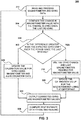
- FIG. 3 diagrammatically illustrates an alternative flow chart, similar to FIG. 1 , in accordance with the compensation method of the present invention, that accomplishes the above described method which utilizes the complex scheme represented by the above algorithm. It will be apparent to one of ordinary skill in the art, that the steps of the method illustrated in FIG. 3 may be performed in different orders without departing from the spirit and scope of the present invention. Like with the flow chart illustrated in FIG. 1 , the flow chart of FIG. 3 is illustrated as an iterative control loop 300 for repetitively compensating for any defined significant changes in the accuracy of the heading system due to soft iron magnetic disturbances.
- the steps may comprise saving the current value of the magnetometer readings; subtracting the current value of the magnetometer readings from the previously saved magnetometer values; dividing the difference in magnetometer readings by the time period to obtain the rate of change; subtracting the determined magnetometer rate of change from the average rate sensor change for the time period; and, if the difference is less than or equal to the maximum expected drift of the rate sensor, using the magnetometer data to compensate for the rate sensor drift. However, if that is not the case, then the rate sensor data is used to compensate for the effect of soft iron on the magnetometer.
- the compensation method of the present invention may comprise the steps of reading the magnetometer data for each axis; reading the gyro data for each axis; converting the gyro data from body to inertial coordinates; determining the rate of change of each magnetic axis based on the magnetometer readings over time; comparing the rate of change of each magnetic axis with the inertial coordinate rate of change of the gyro for the same axis; and, if the difference in rates of change is greater than a predetermined value, recording the difference and using it as a bias to correct for the soft iron impact on each axis of the magnetometer.
- an internal model of the expected magnetic readings for each magnetometer is developed that estimates the expected value of each magnetometer based on estimated heading, pitch and roll of the aircraft as determined by the gyros and accelerometers.
- This model is periodically updated by taking into account the magnetometer readings and, as such, the change in the estimated magnetometer readings is preferably compared with the change in the actual magnetometer reading for each axis and is used to compensate for the effects of soft iron on each magnetometer or to correct the drift on each gyro.
- the steps involved in iteratively carrying out the compensation method of the present invention may involve reading and processing the magnetometer 102, accelerometer 212, and gyro 104 data to provide signals corresponding to any change in magnetometer value and gyro value.
- This step is represented by block 312 in FIG. 3 .
- These signals are then compared against each other to determine any actual change since the previous reading.
- This step is represented by block 314 in FIG. 3 .
- a determination is then made if any detected difference in value from the previous reading is greater than the expected gyro drift over the period since the previous reading.
- This step is represented by block 316 in FIG. 3 .
- the difference exceeds the expected gyro drift, then, in accordance with the compensation method illustrated in FIG. 3 , the gyro change plus the last magnetometer reading is used for the magnetometer value, represented by block 318 in FIG. 3 , and the calibration value for the magnetometer is updated using the difference, represented by block 320 in FIG. 3 .
- the corrected gyro and magnetometer values are then output, represented by block 322 in FIG. 3 , and the best estimate of attitude and heading is computed, represented by block 324 in FIG. 3 , and the steps are iteratively periodically repeated, as illustrated in FIG. 3 .
- the calibration value for the gyro is updated using the magnetometer and the accelerometer data. This step is represented by block 326 in FIG. 3 , and then the corrected gyro and magnetometer values are output, as represented by block 322, the best estimate of attitude and heading is computed, represented by block 324, and the process is iteratively periodically repeated.
- System 400 includes two heading and reference systems such as integrated standby units 200 that are installed at different locations within the vehicle as previously illustrated and discussed in reference to FIG. 2 .
- Each heading and reference system 200 includes triads of sensors (e.g., conventional accelerometers 212, gyros 104 and magnetometers 102) that are utilized for measuring magnetic heading and other parameters required for the navigation of a vehicle.
- a heading and reference system can be any suitable navigation system that includes a triad of sensors such as an attitude and heading reference system, integrated standby unit, a primary and/or secondary vehicle inertial unit and/or any portable system that can be placed inside or outside a vehicle and is capable of measuring navigation parameters.
- System 400 can include two or more integrated standby units 200 where each of them preferably includes a conventional differential pressure transducer 214 and conventional absolute pressure transducer 216 for conventional measurement of airspeed and altitude.
- standby unit 200 also preferably includes a conventional LCD display 222, backlight 224, light sensor 226, internal temperature sensor 228, and bezel controls 230.
- each of the integrated standby units includes microcontroller 120 that receives external inputs from an external configuration module 232 and a static air temperature probe 234.
- each of the above integrated standby units 200 illustrated in FIG. 4 comprises a series of temperature, pressure, magnetic, acceleration and rate sensors controlled by a microcontroller and/or microprocessor, such as a Freescale IMX series microprocessor, and presented on an LCD display.
- the integrated standby unit 200 provides for measurement, computation and display of flight critical information, including indicated and true airspeed, mach, static air temperature, altitude, pitch, roll, slip angle and magnetic heading.
- the integrated standby unit 200 can be further augmented with GPS or other navigation sensors to also provide for display of course, wind and other navigational information.
- system 400 can include any combination of heading reference units such as standby unit 200 combined with an inertial navigation unit, two inertial navigation units and/or any suitable combination thereof.
- the initial attitude and heading information is determined by means of the tri-axial accelerometers 212 and magnetometers 102 in both standby units 200.
- the vehicle or aircraft is assumed to be in zero acceleration state and, therefore, the combination of accelerometers 212 and magnetometers 102 provide an accurate initial state for pitch, roll and heading of the aircraft.
- the tri-axial rate sensors are preferably utilized to determine the current attitude and heading of the aircraft by monitoring and compensating for changes from the initial state.
- Computed angles based on rate sensor data normally suffer from a random drift, generally referred to as random walk. This drift is attributed to the integration of noise which is in the signal bandwidth and, thus, is not easily filtered by traditional signal conditioning algorithms.
- the gyro outputs are periodically recalibrated against the magnetometer and accelerometer data.
- Variations of an extended Kalman filter are preferably used to periodically correct for the rate sensors drift as well as to blend all sensor data based on their corresponding error covariance.
- the internal magnetometers of standby units 200 also suffer from disturbances that result to unreliable measurements.
- the local magnetic environment which surrounds each of the standby units 200 that are installed at different locations within the aircraft is subject to variations such as magnetic effects of power switching to a nearby instrument and/or the presence of other, external electronic circuits that may be present in the vehicle (e.g., smartphones, computers etc.).
- These types of soft iron disturbances affecting the magnetometers are initially compensated for at install time, whereby each of the standby units 200 is calibrated to compensate for the effects of the local environment. Subsequently, a periodic calibration is necessary during the course of a typical flight, since various equipment is normally turned on or off which could result in an error in the magnetic heading measured by the internal magnetometers.
- system 400 also allows for an initial detection of the existence of localized soft iron disturbances by comparing the changes of the local magnetic field as measured by the magnetometers of the respective standby units 200.
- the computational and storage requirements that are associated with the periodic calculation of the navigation parameters and subsequent calibration of the sensors can be minimized by dynamically determining when to perform a calibration process that can be similar to the techniques described in FIGS. 1 and 3 .
- FIG. 5 a flow chart showing method 500 for iteratively correcting for soft iron disturbances in a dual AHRS installation similar to the one referenced in FIG. 4 is provided.
- one and/or both of the standby units 200 exchange the magnetometer 102, accelerometer 212, and gyro 104 sensor data as measured at the different installation locations within the vehicle.
- the sensor data related to internal magnetometers 102 and gyros 104 are read and processed to provide signals corresponding to any change in the magnetometer readings from the immediately previous obtained reading based on a detection period ⁇ t.
- the magnetometer change signal obtained from each of the standby units 200 reflects any deviation of the intensity and direction of the magnetic field as measured by the internal magnetometers during the detection period.
- a pre-determined threshold e.g., "YES" at 506
- the internal magnetometers of standby units 200 can be used to correct the gyro measurements by updating the gyro drift and subsequently calibrating the gyro sensors using the updated gyro drift.
- such calibration can be accomplished by using the magnetometer readings to provide a heading value that can be used to update the gyro drift during the detection period and subsequently be subtracted by the gyro measurements.
- a new heading can be calculated at 514 using the calibrated gyro measurements and the magnetometers.
- detecting an indication of soft iron magnetic disturbances in two or more installations of heading and reference systems may be represented by the following algorithm:
- the acceptable threshold may be determined using theoretical magnetic field values obtained from a model of the Earth's magnetic field. For example, such information can be obtained from a website or any other suitable source and/or database that provides information relating to the Earth's magnetic field.
- the theoretical magnetic field values can be stored in a memory element included in microprocessor 120 of standby unit 200 and accessed during the detection period in order to identify and perform the compensation techniques described herein.
- the difference of the magnetometer change signals from each of the standby units 200 does exceed a pre-defined threshold, indicating that the change of measurements of the internal magnetometers among the two heading and reference systems is not consistent (e.g., "NO" at 506) then a subsequent determination is needed at 508 to detect the heading and reference system that is possibly exposed to soft iron magnetic disturbances and identify its location within the vehicle.
- a determination is accomplished by computing for each standby unit 200 a pair of expected heading values using their respective internal magnetometers and the gyros and computing a difference (e.g., a change signal) between the expected heading as measured by the magnetometers and the gyros for each standby unit 200.
- method 500 proceeds to 512 and uses the internal magnetometers of standby units 200 to correct the gyro measurements by updating the gyro drift and subsequently calibrating the gyro sensors using the updated gyro drift.
- a new heading can be then calculated at 514 using the calibrated gyro measurements and the magnetometers.
- the standby unit exhibiting the largest deviation from the pre-defined threshold is identified as being susceptible to soft iron disturbances thereby requiring calibration of the magnetometers.
- This can be accomplished at 510 by calibrating the magnetometer data using the heading measurement obtained by the gyroscopes.
- a magnetometer calibration value can be computed using the difference of an immediately previous heading measurement obtained from the magnetometers and the current heading as computed from the gyros.
- the computed gyro heading can be obtained from either of the standby units and/or as a combination (e.g., average) from both standby units 200.
- a conventional extended Kalman filter as discussed above in reference with FIG. 2 may also be employed in order to blend the gyro 104 measurements with the magnetometer 102 measurements, with the aforementioned difference between the magnetometers 102 and the gyros 104 that is computed at 508 being dependent on the gyro error covariance.
- FIG. 6 illustrates a flow chart of method 600 for iteratively correcting for soft iron disturbances in magnetometers in a dual heading and reference system installation, as illustrated in FIG. 4 , using data associated with the expected gyro drift as previously discussed in reference to FIGS. 1 and 5 .
- one and/or more of standby units 200 exchange/receive the magnetometer 102, accelerometer 212, and gyro 104 sensor data as measured at the different installation locations within the vehicle.
- the sensor data related to internal magnetometers 102 and gyros 104 are read and processed to provide signals corresponding to any change in the magnetometer readings from the immediately previous obtained reading during a detection period ⁇ t.
- the magnetometer readings provide the intensity and direction of the magnetic field and their computed difference during the detection period reflects any deviation of the local magnetic field.
- a pre-determined threshold e.g., "YES” at 606
- the internal magnetometers of standby units 200 can be used to correct the gyro measurements by updating the gyro drift and subsequently calibrating the gyro sensors using the updated gyro drift.
- such calibration can be accomplished by using the magnetometer readings to provide a heading value that can be used to update the gyro drift during the detection period and subsequently be subtracted from the gyro measurements.
- a new heading can be calculated at 616 using the calibrated gyro measurements and the magnetometers.
- the difference of the magnetometer change signals from each of the standby units 200 does exceed a pre-defined threshold, indicating that the change of measurements of the internal magnetometers among the two heading and reference systems is not consistent (e.g., "NO" at 606) then a subsequent determination is needed at 608 to detect the level of deviation that can be attributed to soft iron magnetic disturbances for one or both of the heading and reference systems.
- a determination is accomplished by detecting whether the difference in value from the previous reading exceeds a pre-determined acceptable threshold value that is defined as the expected gyro drift over the period since the last reading for each standby unit 200.
- method 600 proceeds to 612 and uses the internal magnetometers of standby units 200 to correct the gyro measurements by updating the gyro drift and subsequently calibrating the gyro sensors using the updated gyro drift.
- a new heading can be then calculated at 614 using the calibrated gyro measurements and the magnetometers.
- both standby units 200 may be considered as being affected from soft iron disturbances, thus requiring calibration that can be achieved either in parallel (e.g., simultaneous calibration) and/or sequentially. This can be accomplished at 610 by using the gyro change plus the last magnetometer reading for the magnetometer value and updating, at 614, the calibration value for the magnetometer using the difference.
- the corrected gyro and magnetometer values are then used to calculate the best estimate of attitude and heading, as shown at 616, and the steps are iteratively periodically repeated.
- Such compensation techniques can range from simple to complex as were previously discussed in reference to FIGS. 1-2 .
- a conventional extended Kalman filter as discussed above in reference with FIG. 2 may also be employed in order to blend the gyro 104 measurements with the magnetometer 102 measurements, with the aforementioned difference between the magnetometers 102 and the gyros 104 that is computed at 508 being dependent on the gyro error covariance.
Priority Applications (1)
| Application Number | Priority Date | Filing Date | Title |
|---|---|---|---|
| EP21167506.1A EP3872449B1 (de) | 2016-07-29 | 2017-07-26 | Verfahren und system zur kompensation magnetischer weicheisenstörungen in mehreren kursreferenzsystemen |
Applications Claiming Priority (2)
| Application Number | Priority Date | Filing Date | Title |
|---|---|---|---|
| US15/223,953 US9677889B2 (en) | 2012-06-21 | 2016-07-29 | Method and system for compensating for soft iron magnetic disturbances in multiple heading reference systems |
| US15/592,068 US10139233B2 (en) | 2012-06-21 | 2017-05-10 | Method and system for compensating for soft iron magnetic disturbances in multiple heading reference systems |
Related Child Applications (2)
| Application Number | Title | Priority Date | Filing Date |
|---|---|---|---|
| EP21167506.1A Division-Into EP3872449B1 (de) | 2016-07-29 | 2017-07-26 | Verfahren und system zur kompensation magnetischer weicheisenstörungen in mehreren kursreferenzsystemen |
| EP21167506.1A Division EP3872449B1 (de) | 2016-07-29 | 2017-07-26 | Verfahren und system zur kompensation magnetischer weicheisenstörungen in mehreren kursreferenzsystemen |
Publications (2)
| Publication Number | Publication Date |
|---|---|
| EP3276302A1 true EP3276302A1 (de) | 2018-01-31 |
| EP3276302B1 EP3276302B1 (de) | 2021-05-19 |
Family
ID=59409286
Family Applications (2)
| Application Number | Title | Priority Date | Filing Date |
|---|---|---|---|
| EP21167506.1A Active EP3872449B1 (de) | 2016-07-29 | 2017-07-26 | Verfahren und system zur kompensation magnetischer weicheisenstörungen in mehreren kursreferenzsystemen |
| EP17183362.7A Active EP3276302B1 (de) | 2016-07-29 | 2017-07-26 | Verfahren und system zur kompensation magnetischer weicheisenstörungen in einem mehrfachrichtungsbezugssystem |
Family Applications Before (1)
| Application Number | Title | Priority Date | Filing Date |
|---|---|---|---|
| EP21167506.1A Active EP3872449B1 (de) | 2016-07-29 | 2017-07-26 | Verfahren und system zur kompensation magnetischer weicheisenstörungen in mehreren kursreferenzsystemen |
Country Status (2)
| Country | Link |
|---|---|
| EP (2) | EP3872449B1 (de) |
| JP (1) | JP6983565B2 (de) |
Cited By (4)
| Publication number | Priority date | Publication date | Assignee | Title |
|---|---|---|---|---|
| CN109781144A (zh) * | 2019-01-30 | 2019-05-21 | 京东方科技集团股份有限公司 | 数据校正方法、装置、电子设备及计算机可读存储介质 |
| FR3095041A1 (fr) * | 2019-04-15 | 2020-10-16 | Commissariat à l'Energie Atomique et aux Energies Alternatives | Procede de determination de la position et de l'orientation d'un vehicule |
| US20210139164A1 (en) * | 2015-11-19 | 2021-05-13 | SZ DJI Technology Co., Ltd. | Method, device and system for detecting magnetic field interference |
| WO2024063776A1 (en) * | 2022-09-22 | 2024-03-28 | Google Llc | Calibration quality control using multiple magnetometers |
Citations (12)
| Publication number | Priority date | Publication date | Assignee | Title |
|---|---|---|---|---|
| US4005358A (en) | 1974-10-07 | 1977-01-25 | Simon Foner | Magnetometer with out-of-phase correction |
| US4414753A (en) | 1980-06-05 | 1983-11-15 | Crouzet | Process for compensating the magnetic disturbances in the determination of a magnetic heading, and devices for carrying out this process |
| US4733179A (en) | 1983-12-17 | 1988-03-22 | Robert Bosch Gmbh | Method of determining an interference-magnetic field in a motor vehicle provided with an electronic compass |
| US4843865A (en) | 1988-02-29 | 1989-07-04 | Digicourse, Inc. | Method of calibrating a compass heading |
| US5321631A (en) | 1991-03-07 | 1994-06-14 | Societe Nationale Industrielle Et Aerospatiale | Method and self-contained system for harmonizing equipments on board a vehicle, using means of measuring the earth's gravitational and magnetic fields |
| US5682335A (en) | 1995-04-10 | 1997-10-28 | Eurocopter France | Method and device for simultaneous identification and correction of errors in the measurements of a magnetometer |
| US5737226A (en) | 1995-06-05 | 1998-04-07 | Prince Corporation | Vehicle compass system with automatic calibration |
| US5878370A (en) | 1995-12-01 | 1999-03-02 | Prince Corporation | Vehicle compass system with variable resolution |
| US5990679A (en) | 1997-10-22 | 1999-11-23 | The United States Of America As Represented By The Secretary Of The Navy | Method using corrective factors for determining a magnetic gradient |
| US6860023B2 (en) | 2002-12-30 | 2005-03-01 | Honeywell International Inc. | Methods and apparatus for automatic magnetic compensation |
| US20130106697A1 (en) * | 2011-11-01 | 2013-05-02 | Qualcom Incorporated | System and method for improving orientation data |
| EP2677275A2 (de) * | 2012-06-21 | 2013-12-25 | Innovative Solutions & Support, Inc. | Verfahren und System zur Kompensation magnetischer Weicheisenstörungen in einem Richtungsbezugssystem |
Family Cites Families (4)
| Publication number | Priority date | Publication date | Assignee | Title |
|---|---|---|---|---|
| JPH05164560A (ja) * | 1991-12-17 | 1993-06-29 | Hitachi Cable Ltd | 方位センサ |
| JP3075889B2 (ja) * | 1993-05-31 | 2000-08-14 | 株式会社日立製作所 | ナビゲーション装置 |
| JP3595625B2 (ja) * | 1996-05-15 | 2004-12-02 | 富士重工業株式会社 | 自律走行車の走行制御装置 |
| JPH11248456A (ja) * | 1998-02-27 | 1999-09-17 | Olympus Optical Co Ltd | 3軸姿勢検出装置 |
-
2017
- 2017-07-25 JP JP2017143592A patent/JP6983565B2/ja active Active
- 2017-07-26 EP EP21167506.1A patent/EP3872449B1/de active Active
- 2017-07-26 EP EP17183362.7A patent/EP3276302B1/de active Active
Patent Citations (13)
| Publication number | Priority date | Publication date | Assignee | Title |
|---|---|---|---|---|
| US4005358A (en) | 1974-10-07 | 1977-01-25 | Simon Foner | Magnetometer with out-of-phase correction |
| US4414753A (en) | 1980-06-05 | 1983-11-15 | Crouzet | Process for compensating the magnetic disturbances in the determination of a magnetic heading, and devices for carrying out this process |
| US4733179A (en) | 1983-12-17 | 1988-03-22 | Robert Bosch Gmbh | Method of determining an interference-magnetic field in a motor vehicle provided with an electronic compass |
| US4843865A (en) | 1988-02-29 | 1989-07-04 | Digicourse, Inc. | Method of calibrating a compass heading |
| US5321631A (en) | 1991-03-07 | 1994-06-14 | Societe Nationale Industrielle Et Aerospatiale | Method and self-contained system for harmonizing equipments on board a vehicle, using means of measuring the earth's gravitational and magnetic fields |
| US5682335A (en) | 1995-04-10 | 1997-10-28 | Eurocopter France | Method and device for simultaneous identification and correction of errors in the measurements of a magnetometer |
| US5737226A (en) | 1995-06-05 | 1998-04-07 | Prince Corporation | Vehicle compass system with automatic calibration |
| US5878370A (en) | 1995-12-01 | 1999-03-02 | Prince Corporation | Vehicle compass system with variable resolution |
| US5990679A (en) | 1997-10-22 | 1999-11-23 | The United States Of America As Represented By The Secretary Of The Navy | Method using corrective factors for determining a magnetic gradient |
| US6860023B2 (en) | 2002-12-30 | 2005-03-01 | Honeywell International Inc. | Methods and apparatus for automatic magnetic compensation |
| US7146740B2 (en) | 2002-12-30 | 2006-12-12 | Honeywell International Inc. | Methods and apparatus for automatic magnetic compensation |
| US20130106697A1 (en) * | 2011-11-01 | 2013-05-02 | Qualcom Incorporated | System and method for improving orientation data |
| EP2677275A2 (de) * | 2012-06-21 | 2013-12-25 | Innovative Solutions & Support, Inc. | Verfahren und System zur Kompensation magnetischer Weicheisenstörungen in einem Richtungsbezugssystem |
Cited By (8)
| Publication number | Priority date | Publication date | Assignee | Title |
|---|---|---|---|---|
| US20210139164A1 (en) * | 2015-11-19 | 2021-05-13 | SZ DJI Technology Co., Ltd. | Method, device and system for detecting magnetic field interference |
| CN109781144A (zh) * | 2019-01-30 | 2019-05-21 | 京东方科技集团股份有限公司 | 数据校正方法、装置、电子设备及计算机可读存储介质 |
| CN109781144B (zh) * | 2019-01-30 | 2021-03-19 | 京东方科技集团股份有限公司 | 数据校正方法、装置、电子设备及计算机可读存储介质 |
| US11526580B2 (en) | 2019-01-30 | 2022-12-13 | Beijing Boe Optoelectronics Technology Co., Ltd. | Data correction method and apparatus, electronic device and computer-readable storage medium |
| FR3095041A1 (fr) * | 2019-04-15 | 2020-10-16 | Commissariat à l'Energie Atomique et aux Energies Alternatives | Procede de determination de la position et de l'orientation d'un vehicule |
| EP3726183A1 (de) | 2019-04-15 | 2020-10-21 | Commissariat à l'énergie atomique et aux énergies alternatives | Verfahren zur positionsbestimmung und orientierung eines fahrzeugs |
| US11519730B2 (en) | 2019-04-15 | 2022-12-06 | Commissariat A L'energie Atomique Et Aux Energies Alternatives | Method for determining the position and orientation of a vehicle |
| WO2024063776A1 (en) * | 2022-09-22 | 2024-03-28 | Google Llc | Calibration quality control using multiple magnetometers |
Also Published As
| Publication number | Publication date |
|---|---|
| EP3276302B1 (de) | 2021-05-19 |
| JP2018049000A (ja) | 2018-03-29 |
| EP3872449A1 (de) | 2021-09-01 |
| JP6983565B2 (ja) | 2021-12-17 |
| EP3872449B1 (de) | 2024-04-24 |
Similar Documents
| Publication | Publication Date | Title |
|---|---|---|
| US10139233B2 (en) | Method and system for compensating for soft iron magnetic disturbances in multiple heading reference systems | |
| US10119819B2 (en) | Method and system for compensating for soft iron magnetic disturbances in a heading reference system | |
| EP1340042B1 (de) | Genauigkeitsüberwachung eines elektronischen kompasses | |
| EP3872449B1 (de) | Verfahren und system zur kompensation magnetischer weicheisenstörungen in mehreren kursreferenzsystemen | |
| US6853947B1 (en) | Dynamic attitude measurement method and apparatus | |
| US7216055B1 (en) | Dynamic attitude measurement method and apparatus | |
| JP2014006248A5 (de) | ||
| US10488432B2 (en) | Systems and methods for compensating for the absence of a sensor measurement in a heading reference system | |
| CN110621961A (zh) | 低成本惯性导航系统 | |
| JP2017173315A (ja) | 方位基準システムの較正および調整システムならびに方法 | |
| US5841018A (en) | Method of compensating for installation orientation of an attitude determining device onboard a craft | |
| Akimov et al. | Processing the results of SINS bench tests by methods of nonsmooth optimization in the presence of faults | |
| JPH0287010A (ja) | 人工衛星用角速度測定装置 |
Legal Events
| Date | Code | Title | Description |
|---|---|---|---|
| PUAI | Public reference made under article 153(3) epc to a published international application that has entered the european phase |
Free format text: ORIGINAL CODE: 0009012 |
|
| STAA | Information on the status of an ep patent application or granted ep patent |
Free format text: STATUS: THE APPLICATION HAS BEEN PUBLISHED |
|
| AK | Designated contracting states |
Kind code of ref document: A1 Designated state(s): AL AT BE BG CH CY CZ DE DK EE ES FI FR GB GR HR HU IE IS IT LI LT LU LV MC MK MT NL NO PL PT RO RS SE SI SK SM TR |
|
| AX | Request for extension of the european patent |
Extension state: BA ME |
|
| STAA | Information on the status of an ep patent application or granted ep patent |
Free format text: STATUS: REQUEST FOR EXAMINATION WAS MADE |
|
| 17P | Request for examination filed |
Effective date: 20180702 |
|
| RBV | Designated contracting states (corrected) |
Designated state(s): AL AT BE BG CH CY CZ DE DK EE ES FI FR GB GR HR HU IE IS IT LI LT LU LV MC MK MT NL NO PL PT RO RS SE SI SK SM TR |
|
| RIC1 | Information provided on ipc code assigned before grant |
Ipc: G01C 1/00 20060101AFI20201005BHEP Ipc: G01C 25/00 20060101ALI20201005BHEP Ipc: G01C 21/16 20060101ALI20201005BHEP Ipc: G01R 33/00 20060101ALI20201005BHEP Ipc: G01C 17/38 20060101ALI20201005BHEP |
|
| GRAP | Despatch of communication of intention to grant a patent |
Free format text: ORIGINAL CODE: EPIDOSNIGR1 |
|
| STAA | Information on the status of an ep patent application or granted ep patent |
Free format text: STATUS: GRANT OF PATENT IS INTENDED |
|
| INTG | Intention to grant announced |
Effective date: 20201201 |
|
| GRAS | Grant fee paid |
Free format text: ORIGINAL CODE: EPIDOSNIGR3 |
|
| GRAA | (expected) grant |
Free format text: ORIGINAL CODE: 0009210 |
|
| STAA | Information on the status of an ep patent application or granted ep patent |
Free format text: STATUS: THE PATENT HAS BEEN GRANTED |
|
| RAP3 | Party data changed (applicant data changed or rights of an application transferred) |
Owner name: INNOVATIVE SOLUTIONS & SUPPORT, INC. |
|
| AK | Designated contracting states |
Kind code of ref document: B1 Designated state(s): AL AT BE BG CH CY CZ DE DK EE ES FI FR GB GR HR HU IE IS IT LI LT LU LV MC MK MT NL NO PL PT RO RS SE SI SK SM TR |
|
| REG | Reference to a national code |
Ref country code: GB Ref legal event code: FG4D |
|
| REG | Reference to a national code |
Ref country code: CH Ref legal event code: EP |
|
| REG | Reference to a national code |
Ref country code: DE Ref legal event code: R096 Ref document number: 602017038730 Country of ref document: DE |
|
| REG | Reference to a national code |
Ref country code: AT Ref legal event code: REF Ref document number: 1394413 Country of ref document: AT Kind code of ref document: T Effective date: 20210615 |
|
| REG | Reference to a national code |
Ref country code: IE Ref legal event code: FG4D |
|
| REG | Reference to a national code |
Ref country code: LT Ref legal event code: MG9D |
|
| REG | Reference to a national code |
Ref country code: AT Ref legal event code: MK05 Ref document number: 1394413 Country of ref document: AT Kind code of ref document: T Effective date: 20210519 |
|
| REG | Reference to a national code |
Ref country code: NL Ref legal event code: MP Effective date: 20210519 |
|
| PG25 | Lapsed in a contracting state [announced via postgrant information from national office to epo] |
Ref country code: HR Free format text: LAPSE BECAUSE OF FAILURE TO SUBMIT A TRANSLATION OF THE DESCRIPTION OR TO PAY THE FEE WITHIN THE PRESCRIBED TIME-LIMIT Effective date: 20210519 Ref country code: AT Free format text: LAPSE BECAUSE OF FAILURE TO SUBMIT A TRANSLATION OF THE DESCRIPTION OR TO PAY THE FEE WITHIN THE PRESCRIBED TIME-LIMIT Effective date: 20210519 Ref country code: BG Free format text: LAPSE BECAUSE OF FAILURE TO SUBMIT A TRANSLATION OF THE DESCRIPTION OR TO PAY THE FEE WITHIN THE PRESCRIBED TIME-LIMIT Effective date: 20210819 Ref country code: FI Free format text: LAPSE BECAUSE OF FAILURE TO SUBMIT A TRANSLATION OF THE DESCRIPTION OR TO PAY THE FEE WITHIN THE PRESCRIBED TIME-LIMIT Effective date: 20210519 Ref country code: LT Free format text: LAPSE BECAUSE OF FAILURE TO SUBMIT A TRANSLATION OF THE DESCRIPTION OR TO PAY THE FEE WITHIN THE PRESCRIBED TIME-LIMIT Effective date: 20210519 |
|
| PG25 | Lapsed in a contracting state [announced via postgrant information from national office to epo] |
Ref country code: PL Free format text: LAPSE BECAUSE OF FAILURE TO SUBMIT A TRANSLATION OF THE DESCRIPTION OR TO PAY THE FEE WITHIN THE PRESCRIBED TIME-LIMIT Effective date: 20210519 Ref country code: PT Free format text: LAPSE BECAUSE OF FAILURE TO SUBMIT A TRANSLATION OF THE DESCRIPTION OR TO PAY THE FEE WITHIN THE PRESCRIBED TIME-LIMIT Effective date: 20210920 Ref country code: NO Free format text: LAPSE BECAUSE OF FAILURE TO SUBMIT A TRANSLATION OF THE DESCRIPTION OR TO PAY THE FEE WITHIN THE PRESCRIBED TIME-LIMIT Effective date: 20210819 Ref country code: SE Free format text: LAPSE BECAUSE OF FAILURE TO SUBMIT A TRANSLATION OF THE DESCRIPTION OR TO PAY THE FEE WITHIN THE PRESCRIBED TIME-LIMIT Effective date: 20210519 Ref country code: RS Free format text: LAPSE BECAUSE OF FAILURE TO SUBMIT A TRANSLATION OF THE DESCRIPTION OR TO PAY THE FEE WITHIN THE PRESCRIBED TIME-LIMIT Effective date: 20210519 Ref country code: GR Free format text: LAPSE BECAUSE OF FAILURE TO SUBMIT A TRANSLATION OF THE DESCRIPTION OR TO PAY THE FEE WITHIN THE PRESCRIBED TIME-LIMIT Effective date: 20210820 Ref country code: IS Free format text: LAPSE BECAUSE OF FAILURE TO SUBMIT A TRANSLATION OF THE DESCRIPTION OR TO PAY THE FEE WITHIN THE PRESCRIBED TIME-LIMIT Effective date: 20210919 Ref country code: LV Free format text: LAPSE BECAUSE OF FAILURE TO SUBMIT A TRANSLATION OF THE DESCRIPTION OR TO PAY THE FEE WITHIN THE PRESCRIBED TIME-LIMIT Effective date: 20210519 |
|
| PG25 | Lapsed in a contracting state [announced via postgrant information from national office to epo] |
Ref country code: NL Free format text: LAPSE BECAUSE OF FAILURE TO SUBMIT A TRANSLATION OF THE DESCRIPTION OR TO PAY THE FEE WITHIN THE PRESCRIBED TIME-LIMIT Effective date: 20210519 |
|
| PG25 | Lapsed in a contracting state [announced via postgrant information from national office to epo] |
Ref country code: ES Free format text: LAPSE BECAUSE OF FAILURE TO SUBMIT A TRANSLATION OF THE DESCRIPTION OR TO PAY THE FEE WITHIN THE PRESCRIBED TIME-LIMIT Effective date: 20210519 Ref country code: RO Free format text: LAPSE BECAUSE OF FAILURE TO SUBMIT A TRANSLATION OF THE DESCRIPTION OR TO PAY THE FEE WITHIN THE PRESCRIBED TIME-LIMIT Effective date: 20210519 Ref country code: EE Free format text: LAPSE BECAUSE OF FAILURE TO SUBMIT A TRANSLATION OF THE DESCRIPTION OR TO PAY THE FEE WITHIN THE PRESCRIBED TIME-LIMIT Effective date: 20210519 Ref country code: CZ Free format text: LAPSE BECAUSE OF FAILURE TO SUBMIT A TRANSLATION OF THE DESCRIPTION OR TO PAY THE FEE WITHIN THE PRESCRIBED TIME-LIMIT Effective date: 20210519 Ref country code: DK Free format text: LAPSE BECAUSE OF FAILURE TO SUBMIT A TRANSLATION OF THE DESCRIPTION OR TO PAY THE FEE WITHIN THE PRESCRIBED TIME-LIMIT Effective date: 20210519 Ref country code: SM Free format text: LAPSE BECAUSE OF FAILURE TO SUBMIT A TRANSLATION OF THE DESCRIPTION OR TO PAY THE FEE WITHIN THE PRESCRIBED TIME-LIMIT Effective date: 20210519 Ref country code: SK Free format text: LAPSE BECAUSE OF FAILURE TO SUBMIT A TRANSLATION OF THE DESCRIPTION OR TO PAY THE FEE WITHIN THE PRESCRIBED TIME-LIMIT Effective date: 20210519 |
|
| REG | Reference to a national code |
Ref country code: DE Ref legal event code: R097 Ref document number: 602017038730 Country of ref document: DE |
|
| REG | Reference to a national code |
Ref country code: CH Ref legal event code: PL |
|
| PLBE | No opposition filed within time limit |
Free format text: ORIGINAL CODE: 0009261 |
|
| STAA | Information on the status of an ep patent application or granted ep patent |
Free format text: STATUS: NO OPPOSITION FILED WITHIN TIME LIMIT |
|
| PG25 | Lapsed in a contracting state [announced via postgrant information from national office to epo] |
Ref country code: MC Free format text: LAPSE BECAUSE OF FAILURE TO SUBMIT A TRANSLATION OF THE DESCRIPTION OR TO PAY THE FEE WITHIN THE PRESCRIBED TIME-LIMIT Effective date: 20210519 |
|
| REG | Reference to a national code |
Ref country code: BE Ref legal event code: MM Effective date: 20210731 |
|
| 26N | No opposition filed |
Effective date: 20220222 |
|
| PG25 | Lapsed in a contracting state [announced via postgrant information from national office to epo] |
Ref country code: LI Free format text: LAPSE BECAUSE OF NON-PAYMENT OF DUE FEES Effective date: 20210731 Ref country code: CH Free format text: LAPSE BECAUSE OF NON-PAYMENT OF DUE FEES Effective date: 20210731 |
|
| PG25 | Lapsed in a contracting state [announced via postgrant information from national office to epo] |
Ref country code: IS Free format text: LAPSE BECAUSE OF FAILURE TO SUBMIT A TRANSLATION OF THE DESCRIPTION OR TO PAY THE FEE WITHIN THE PRESCRIBED TIME-LIMIT Effective date: 20210919 Ref country code: AL Free format text: LAPSE BECAUSE OF FAILURE TO SUBMIT A TRANSLATION OF THE DESCRIPTION OR TO PAY THE FEE WITHIN THE PRESCRIBED TIME-LIMIT Effective date: 20210519 Ref country code: LU Free format text: LAPSE BECAUSE OF NON-PAYMENT OF DUE FEES Effective date: 20210726 |
|
| PG25 | Lapsed in a contracting state [announced via postgrant information from national office to epo] |
Ref country code: IT Free format text: LAPSE BECAUSE OF FAILURE TO SUBMIT A TRANSLATION OF THE DESCRIPTION OR TO PAY THE FEE WITHIN THE PRESCRIBED TIME-LIMIT Effective date: 20210519 Ref country code: IE Free format text: LAPSE BECAUSE OF NON-PAYMENT OF DUE FEES Effective date: 20210726 Ref country code: BE Free format text: LAPSE BECAUSE OF NON-PAYMENT OF DUE FEES Effective date: 20210731 |
|
| PG25 | Lapsed in a contracting state [announced via postgrant information from national office to epo] |
Ref country code: HU Free format text: LAPSE BECAUSE OF FAILURE TO SUBMIT A TRANSLATION OF THE DESCRIPTION OR TO PAY THE FEE WITHIN THE PRESCRIBED TIME-LIMIT; INVALID AB INITIO Effective date: 20170726 |
|
| PG25 | Lapsed in a contracting state [announced via postgrant information from national office to epo] |
Ref country code: CY Free format text: LAPSE BECAUSE OF FAILURE TO SUBMIT A TRANSLATION OF THE DESCRIPTION OR TO PAY THE FEE WITHIN THE PRESCRIBED TIME-LIMIT Effective date: 20210519 |
|
| P01 | Opt-out of the competence of the unified patent court (upc) registered |
Effective date: 20230525 |
|
| PGFP | Annual fee paid to national office [announced via postgrant information from national office to epo] |
Ref country code: FR Payment date: 20230623 Year of fee payment: 7 |
|
| PGFP | Annual fee paid to national office [announced via postgrant information from national office to epo] |
Ref country code: GB Payment date: 20230620 Year of fee payment: 7 |
|
| PGFP | Annual fee paid to national office [announced via postgrant information from national office to epo] |
Ref country code: DE Payment date: 20230623 Year of fee payment: 7 |
|
| PG25 | Lapsed in a contracting state [announced via postgrant information from national office to epo] |
Ref country code: MK Free format text: LAPSE BECAUSE OF FAILURE TO SUBMIT A TRANSLATION OF THE DESCRIPTION OR TO PAY THE FEE WITHIN THE PRESCRIBED TIME-LIMIT Effective date: 20210519 |