EP3276011B1 - Method for manufacturing an insulation-coated oriented magnetic steel sheet - Google Patents
Method for manufacturing an insulation-coated oriented magnetic steel sheet Download PDFInfo
- Publication number
- EP3276011B1 EP3276011B1 EP16772206.5A EP16772206A EP3276011B1 EP 3276011 B1 EP3276011 B1 EP 3276011B1 EP 16772206 A EP16772206 A EP 16772206A EP 3276011 B1 EP3276011 B1 EP 3276011B1
- Authority
- EP
- European Patent Office
- Prior art keywords
- steel sheet
- insulating coating
- baking
- oriented electrical
- electrical steel
- Prior art date
- Legal status (The legal status is an assumption and is not a legal conclusion. Google has not performed a legal analysis and makes no representation as to the accuracy of the status listed.)
- Active
Links
- 238000004519 manufacturing process Methods 0.000 title claims description 18
- 229910000831 Steel Inorganic materials 0.000 title description 42
- 239000010959 steel Substances 0.000 title description 42
- 238000000034 method Methods 0.000 title description 32
- 238000009413 insulation Methods 0.000 title description 3
- 238000000576 coating method Methods 0.000 claims description 134
- 239000011248 coating agent Substances 0.000 claims description 127
- 229910001224 Grain-oriented electrical steel Inorganic materials 0.000 claims description 53
- WGLPBDUCMAPZCE-UHFFFAOYSA-N Trioxochromium Chemical compound O=[Cr](=O)=O WGLPBDUCMAPZCE-UHFFFAOYSA-N 0.000 claims description 36
- 229910019142 PO4 Inorganic materials 0.000 claims description 31
- 239000010452 phosphate Substances 0.000 claims description 26
- NBIIXXVUZAFLBC-UHFFFAOYSA-K phosphate Chemical compound [O-]P([O-])([O-])=O NBIIXXVUZAFLBC-UHFFFAOYSA-K 0.000 claims description 25
- VYPSYNLAJGMNEJ-UHFFFAOYSA-N Silicium dioxide Chemical compound O=[Si]=O VYPSYNLAJGMNEJ-UHFFFAOYSA-N 0.000 claims description 22
- 238000009832 plasma treatment Methods 0.000 claims description 22
- UFHFLCQGNIYNRP-UHFFFAOYSA-N Hydrogen Chemical compound [H][H] UFHFLCQGNIYNRP-UHFFFAOYSA-N 0.000 claims description 21
- 238000000137 annealing Methods 0.000 claims description 21
- 239000001257 hydrogen Substances 0.000 claims description 21
- 229910052739 hydrogen Inorganic materials 0.000 claims description 21
- 239000008119 colloidal silica Substances 0.000 claims description 20
- 150000001875 compounds Chemical class 0.000 claims description 19
- 239000007787 solid Substances 0.000 claims description 19
- 238000000026 X-ray photoelectron spectrum Methods 0.000 claims description 13
- 239000007789 gas Substances 0.000 claims description 13
- 239000012298 atmosphere Substances 0.000 claims description 12
- 229910052782 aluminium Inorganic materials 0.000 claims description 11
- 229910052749 magnesium Inorganic materials 0.000 claims description 11
- 229910052791 calcium Inorganic materials 0.000 claims description 10
- 229910052748 manganese Inorganic materials 0.000 claims description 10
- 229910052725 zinc Inorganic materials 0.000 claims description 10
- 229910052788 barium Inorganic materials 0.000 claims description 9
- 229910052712 strontium Inorganic materials 0.000 claims description 9
- 229910052804 chromium Inorganic materials 0.000 claims description 5
- 229910052710 silicon Inorganic materials 0.000 claims description 5
- 229910052760 oxygen Inorganic materials 0.000 claims description 4
- 229910052698 phosphorus Inorganic materials 0.000 claims description 4
- 230000001678 irradiating effect Effects 0.000 claims description 2
- 230000000717 retained effect Effects 0.000 claims description 2
- 239000000243 solution Substances 0.000 description 39
- 239000011651 chromium Substances 0.000 description 32
- 235000021317 phosphate Nutrition 0.000 description 28
- XEEYBQQBJWHFJM-UHFFFAOYSA-N Iron Chemical compound [Fe] XEEYBQQBJWHFJM-UHFFFAOYSA-N 0.000 description 16
- 238000001035 drying Methods 0.000 description 14
- 238000001228 spectrum Methods 0.000 description 12
- 239000011777 magnesium Substances 0.000 description 9
- NBIIXXVUZAFLBC-UHFFFAOYSA-N Phosphoric acid Chemical compound OP(O)(O)=O NBIIXXVUZAFLBC-UHFFFAOYSA-N 0.000 description 8
- 238000004458 analytical method Methods 0.000 description 8
- 239000011575 calcium Substances 0.000 description 8
- 229910052742 iron Inorganic materials 0.000 description 8
- 238000003475 lamination Methods 0.000 description 8
- 239000011572 manganese Substances 0.000 description 8
- 239000011701 zinc Substances 0.000 description 8
- IJGRMHOSHXDMSA-UHFFFAOYSA-N Atomic nitrogen Chemical compound N#N IJGRMHOSHXDMSA-UHFFFAOYSA-N 0.000 description 6
- 230000015572 biosynthetic process Effects 0.000 description 5
- 230000007797 corrosion Effects 0.000 description 5
- 238000005260 corrosion Methods 0.000 description 5
- 239000012299 nitrogen atmosphere Substances 0.000 description 5
- 150000003013 phosphoric acid derivatives Chemical class 0.000 description 5
- 238000007790 scraping Methods 0.000 description 5
- 229910000147 aluminium phosphate Inorganic materials 0.000 description 4
- 239000007864 aqueous solution Substances 0.000 description 4
- 238000002425 crystallisation Methods 0.000 description 4
- 230000008025 crystallization Effects 0.000 description 4
- 239000002245 particle Substances 0.000 description 4
- -1 chromic acid compound Chemical class 0.000 description 3
- 238000011068 loading method Methods 0.000 description 3
- 238000005259 measurement Methods 0.000 description 3
- 229910052757 nitrogen Inorganic materials 0.000 description 3
- XKRFYHLGVUSROY-UHFFFAOYSA-N Argon Chemical compound [Ar] XKRFYHLGVUSROY-UHFFFAOYSA-N 0.000 description 2
- 229910052786 argon Inorganic materials 0.000 description 2
- 230000008859 change Effects 0.000 description 2
- ZCDOYSPFYFSLEW-UHFFFAOYSA-N chromate(2-) Chemical compound [O-][Cr]([O-])(=O)=O ZCDOYSPFYFSLEW-UHFFFAOYSA-N 0.000 description 2
- 238000005097 cold rolling Methods 0.000 description 2
- 230000007547 defect Effects 0.000 description 2
- 230000000694 effects Effects 0.000 description 2
- 230000002349 favourable effect Effects 0.000 description 2
- 239000010419 fine particle Substances 0.000 description 2
- 230000004907 flux Effects 0.000 description 2
- 229910052751 metal Inorganic materials 0.000 description 2
- 239000002184 metal Substances 0.000 description 2
- 230000008569 process Effects 0.000 description 2
- 229910052708 sodium Inorganic materials 0.000 description 2
- 238000004438 BET method Methods 0.000 description 1
- 229910000576 Laminated steel Inorganic materials 0.000 description 1
- NBIIXXVUZAFLBC-UHFFFAOYSA-L Phosphate ion(2-) Chemical compound OP([O-])([O-])=O NBIIXXVUZAFLBC-UHFFFAOYSA-L 0.000 description 1
- XUIMIQQOPSSXEZ-UHFFFAOYSA-N Silicon Chemical compound [Si] XUIMIQQOPSSXEZ-UHFFFAOYSA-N 0.000 description 1
- 238000010521 absorption reaction Methods 0.000 description 1
- 229910052783 alkali metal Inorganic materials 0.000 description 1
- 150000001340 alkali metals Chemical class 0.000 description 1
- XAGFODPZIPBFFR-UHFFFAOYSA-N aluminium Chemical compound [Al] XAGFODPZIPBFFR-UHFFFAOYSA-N 0.000 description 1
- ILRRQNADMUWWFW-UHFFFAOYSA-K aluminium phosphate Chemical compound O1[Al]2OP1(=O)O2 ILRRQNADMUWWFW-UHFFFAOYSA-K 0.000 description 1
- 230000009286 beneficial effect Effects 0.000 description 1
- KRVSOGSZCMJSLX-UHFFFAOYSA-L chromic acid Substances O[Cr](O)(=O)=O KRVSOGSZCMJSLX-UHFFFAOYSA-L 0.000 description 1
- JOPOVCBBYLSVDA-UHFFFAOYSA-N chromium(6+) Chemical compound [Cr+6] JOPOVCBBYLSVDA-UHFFFAOYSA-N 0.000 description 1
- 229910052681 coesite Inorganic materials 0.000 description 1
- 230000000052 comparative effect Effects 0.000 description 1
- 229910052906 cristobalite Inorganic materials 0.000 description 1
- 230000006866 deterioration Effects 0.000 description 1
- SOCTUWSJJQCPFX-UHFFFAOYSA-N dichromate(2-) Chemical compound [O-][Cr](=O)(=O)O[Cr]([O-])(=O)=O SOCTUWSJJQCPFX-UHFFFAOYSA-N 0.000 description 1
- 238000000635 electron micrograph Methods 0.000 description 1
- 229910052839 forsterite Inorganic materials 0.000 description 1
- 238000010438 heat treatment Methods 0.000 description 1
- 239000001307 helium Substances 0.000 description 1
- 229910052734 helium Inorganic materials 0.000 description 1
- SWQJXJOGLNCZEY-UHFFFAOYSA-N helium atom Chemical compound [He] SWQJXJOGLNCZEY-UHFFFAOYSA-N 0.000 description 1
- 238000005098 hot rolling Methods 0.000 description 1
- 230000001771 impaired effect Effects 0.000 description 1
- 230000006872 improvement Effects 0.000 description 1
- 239000011261 inert gas Substances 0.000 description 1
- 238000010884 ion-beam technique Methods 0.000 description 1
- NLYAJNPCOHFWQQ-UHFFFAOYSA-N kaolin Chemical compound O.O.O=[Al]O[Si](=O)O[Si](=O)O[Al]=O NLYAJNPCOHFWQQ-UHFFFAOYSA-N 0.000 description 1
- 229910052744 lithium Inorganic materials 0.000 description 1
- HCWCAKKEBCNQJP-UHFFFAOYSA-N magnesium orthosilicate Chemical compound [Mg+2].[Mg+2].[O-][Si]([O-])([O-])[O-] HCWCAKKEBCNQJP-UHFFFAOYSA-N 0.000 description 1
- GVALZJMUIHGIMD-UHFFFAOYSA-H magnesium phosphate Chemical compound [Mg+2].[Mg+2].[Mg+2].[O-]P([O-])([O-])=O.[O-]P([O-])([O-])=O GVALZJMUIHGIMD-UHFFFAOYSA-H 0.000 description 1
- 239000004137 magnesium phosphate Substances 0.000 description 1
- 229910000157 magnesium phosphate Inorganic materials 0.000 description 1
- 229960002261 magnesium phosphate Drugs 0.000 description 1
- 235000010994 magnesium phosphates Nutrition 0.000 description 1
- QQFLQYOOQVLGTQ-UHFFFAOYSA-L magnesium;dihydrogen phosphate Chemical compound [Mg+2].OP(O)([O-])=O.OP(O)([O-])=O QQFLQYOOQVLGTQ-UHFFFAOYSA-L 0.000 description 1
- 230000007246 mechanism Effects 0.000 description 1
- 229910052750 molybdenum Inorganic materials 0.000 description 1
- 230000003647 oxidation Effects 0.000 description 1
- 238000007254 oxidation reaction Methods 0.000 description 1
- 230000000704 physical effect Effects 0.000 description 1
- 229910052700 potassium Inorganic materials 0.000 description 1
- 238000001953 recrystallisation Methods 0.000 description 1
- 230000009467 reduction Effects 0.000 description 1
- 230000000246 remedial effect Effects 0.000 description 1
- 239000010703 silicon Substances 0.000 description 1
- 239000000377 silicon dioxide Substances 0.000 description 1
- 238000001179 sorption measurement Methods 0.000 description 1
- 241000894007 species Species 0.000 description 1
- 229910052682 stishovite Inorganic materials 0.000 description 1
- 239000000126 substance Substances 0.000 description 1
- 229910052905 tridymite Inorganic materials 0.000 description 1
Images

Classifications
-
- C—CHEMISTRY; METALLURGY
- C23—COATING METALLIC MATERIAL; COATING MATERIAL WITH METALLIC MATERIAL; CHEMICAL SURFACE TREATMENT; DIFFUSION TREATMENT OF METALLIC MATERIAL; COATING BY VACUUM EVAPORATION, BY SPUTTERING, BY ION IMPLANTATION OR BY CHEMICAL VAPOUR DEPOSITION, IN GENERAL; INHIBITING CORROSION OF METALLIC MATERIAL OR INCRUSTATION IN GENERAL
- C23C—COATING METALLIC MATERIAL; COATING MATERIAL WITH METALLIC MATERIAL; SURFACE TREATMENT OF METALLIC MATERIAL BY DIFFUSION INTO THE SURFACE, BY CHEMICAL CONVERSION OR SUBSTITUTION; COATING BY VACUUM EVAPORATION, BY SPUTTERING, BY ION IMPLANTATION OR BY CHEMICAL VAPOUR DEPOSITION, IN GENERAL
- C23C22/00—Chemical surface treatment of metallic material by reaction of the surface with a reactive liquid, leaving reaction products of surface material in the coating, e.g. conversion coatings, passivation of metals
- C23C22/05—Chemical surface treatment of metallic material by reaction of the surface with a reactive liquid, leaving reaction products of surface material in the coating, e.g. conversion coatings, passivation of metals using aqueous solutions
- C23C22/06—Chemical surface treatment of metallic material by reaction of the surface with a reactive liquid, leaving reaction products of surface material in the coating, e.g. conversion coatings, passivation of metals using aqueous solutions using aqueous acidic solutions with pH less than 6
- C23C22/24—Chemical surface treatment of metallic material by reaction of the surface with a reactive liquid, leaving reaction products of surface material in the coating, e.g. conversion coatings, passivation of metals using aqueous solutions using aqueous acidic solutions with pH less than 6 containing hexavalent chromium compounds
- C23C22/33—Chemical surface treatment of metallic material by reaction of the surface with a reactive liquid, leaving reaction products of surface material in the coating, e.g. conversion coatings, passivation of metals using aqueous solutions using aqueous acidic solutions with pH less than 6 containing hexavalent chromium compounds containing also phosphates
-
- C—CHEMISTRY; METALLURGY
- C21—METALLURGY OF IRON
- C21D—MODIFYING THE PHYSICAL STRUCTURE OF FERROUS METALS; GENERAL DEVICES FOR HEAT TREATMENT OF FERROUS OR NON-FERROUS METALS OR ALLOYS; MAKING METAL MALLEABLE, e.g. BY DECARBURISATION OR TEMPERING
- C21D8/00—Modifying the physical properties by deformation combined with, or followed by, heat treatment
- C21D8/12—Modifying the physical properties by deformation combined with, or followed by, heat treatment during manufacturing of articles with special electromagnetic properties
- C21D8/1277—Modifying the physical properties by deformation combined with, or followed by, heat treatment during manufacturing of articles with special electromagnetic properties involving a particular surface treatment
- C21D8/1283—Application of a separating or insulating coating
-
- C—CHEMISTRY; METALLURGY
- C21—METALLURGY OF IRON
- C21D—MODIFYING THE PHYSICAL STRUCTURE OF FERROUS METALS; GENERAL DEVICES FOR HEAT TREATMENT OF FERROUS OR NON-FERROUS METALS OR ALLOYS; MAKING METAL MALLEABLE, e.g. BY DECARBURISATION OR TEMPERING
- C21D9/00—Heat treatment, e.g. annealing, hardening, quenching or tempering, adapted for particular articles; Furnaces therefor
- C21D9/46—Heat treatment, e.g. annealing, hardening, quenching or tempering, adapted for particular articles; Furnaces therefor for sheet metals
-
- C—CHEMISTRY; METALLURGY
- C22—METALLURGY; FERROUS OR NON-FERROUS ALLOYS; TREATMENT OF ALLOYS OR NON-FERROUS METALS
- C22C—ALLOYS
- C22C38/00—Ferrous alloys, e.g. steel alloys
-
- C—CHEMISTRY; METALLURGY
- C23—COATING METALLIC MATERIAL; COATING MATERIAL WITH METALLIC MATERIAL; CHEMICAL SURFACE TREATMENT; DIFFUSION TREATMENT OF METALLIC MATERIAL; COATING BY VACUUM EVAPORATION, BY SPUTTERING, BY ION IMPLANTATION OR BY CHEMICAL VAPOUR DEPOSITION, IN GENERAL; INHIBITING CORROSION OF METALLIC MATERIAL OR INCRUSTATION IN GENERAL
- C23C—COATING METALLIC MATERIAL; COATING MATERIAL WITH METALLIC MATERIAL; SURFACE TREATMENT OF METALLIC MATERIAL BY DIFFUSION INTO THE SURFACE, BY CHEMICAL CONVERSION OR SUBSTITUTION; COATING BY VACUUM EVAPORATION, BY SPUTTERING, BY ION IMPLANTATION OR BY CHEMICAL VAPOUR DEPOSITION, IN GENERAL
- C23C22/00—Chemical surface treatment of metallic material by reaction of the surface with a reactive liquid, leaving reaction products of surface material in the coating, e.g. conversion coatings, passivation of metals
- C23C22/05—Chemical surface treatment of metallic material by reaction of the surface with a reactive liquid, leaving reaction products of surface material in the coating, e.g. conversion coatings, passivation of metals using aqueous solutions
- C23C22/06—Chemical surface treatment of metallic material by reaction of the surface with a reactive liquid, leaving reaction products of surface material in the coating, e.g. conversion coatings, passivation of metals using aqueous solutions using aqueous acidic solutions with pH less than 6
- C23C22/07—Chemical surface treatment of metallic material by reaction of the surface with a reactive liquid, leaving reaction products of surface material in the coating, e.g. conversion coatings, passivation of metals using aqueous solutions using aqueous acidic solutions with pH less than 6 containing phosphates
- C23C22/08—Orthophosphates
- C23C22/22—Orthophosphates containing alkaline earth metal cations
-
- C—CHEMISTRY; METALLURGY
- C23—COATING METALLIC MATERIAL; COATING MATERIAL WITH METALLIC MATERIAL; CHEMICAL SURFACE TREATMENT; DIFFUSION TREATMENT OF METALLIC MATERIAL; COATING BY VACUUM EVAPORATION, BY SPUTTERING, BY ION IMPLANTATION OR BY CHEMICAL VAPOUR DEPOSITION, IN GENERAL; INHIBITING CORROSION OF METALLIC MATERIAL OR INCRUSTATION IN GENERAL
- C23C—COATING METALLIC MATERIAL; COATING MATERIAL WITH METALLIC MATERIAL; SURFACE TREATMENT OF METALLIC MATERIAL BY DIFFUSION INTO THE SURFACE, BY CHEMICAL CONVERSION OR SUBSTITUTION; COATING BY VACUUM EVAPORATION, BY SPUTTERING, BY ION IMPLANTATION OR BY CHEMICAL VAPOUR DEPOSITION, IN GENERAL
- C23C22/00—Chemical surface treatment of metallic material by reaction of the surface with a reactive liquid, leaving reaction products of surface material in the coating, e.g. conversion coatings, passivation of metals
- C23C22/73—Chemical surface treatment of metallic material by reaction of the surface with a reactive liquid, leaving reaction products of surface material in the coating, e.g. conversion coatings, passivation of metals characterised by the process
- C23C22/74—Chemical surface treatment of metallic material by reaction of the surface with a reactive liquid, leaving reaction products of surface material in the coating, e.g. conversion coatings, passivation of metals characterised by the process for obtaining burned-in conversion coatings
-
- C—CHEMISTRY; METALLURGY
- C23—COATING METALLIC MATERIAL; COATING MATERIAL WITH METALLIC MATERIAL; CHEMICAL SURFACE TREATMENT; DIFFUSION TREATMENT OF METALLIC MATERIAL; COATING BY VACUUM EVAPORATION, BY SPUTTERING, BY ION IMPLANTATION OR BY CHEMICAL VAPOUR DEPOSITION, IN GENERAL; INHIBITING CORROSION OF METALLIC MATERIAL OR INCRUSTATION IN GENERAL
- C23C—COATING METALLIC MATERIAL; COATING MATERIAL WITH METALLIC MATERIAL; SURFACE TREATMENT OF METALLIC MATERIAL BY DIFFUSION INTO THE SURFACE, BY CHEMICAL CONVERSION OR SUBSTITUTION; COATING BY VACUUM EVAPORATION, BY SPUTTERING, BY ION IMPLANTATION OR BY CHEMICAL VAPOUR DEPOSITION, IN GENERAL
- C23C22/00—Chemical surface treatment of metallic material by reaction of the surface with a reactive liquid, leaving reaction products of surface material in the coating, e.g. conversion coatings, passivation of metals
- C23C22/78—Pretreatment of the material to be coated
-
- C—CHEMISTRY; METALLURGY
- C23—COATING METALLIC MATERIAL; COATING MATERIAL WITH METALLIC MATERIAL; CHEMICAL SURFACE TREATMENT; DIFFUSION TREATMENT OF METALLIC MATERIAL; COATING BY VACUUM EVAPORATION, BY SPUTTERING, BY ION IMPLANTATION OR BY CHEMICAL VAPOUR DEPOSITION, IN GENERAL; INHIBITING CORROSION OF METALLIC MATERIAL OR INCRUSTATION IN GENERAL
- C23C—COATING METALLIC MATERIAL; COATING MATERIAL WITH METALLIC MATERIAL; SURFACE TREATMENT OF METALLIC MATERIAL BY DIFFUSION INTO THE SURFACE, BY CHEMICAL CONVERSION OR SUBSTITUTION; COATING BY VACUUM EVAPORATION, BY SPUTTERING, BY ION IMPLANTATION OR BY CHEMICAL VAPOUR DEPOSITION, IN GENERAL
- C23C22/00—Chemical surface treatment of metallic material by reaction of the surface with a reactive liquid, leaving reaction products of surface material in the coating, e.g. conversion coatings, passivation of metals
- C23C22/82—After-treatment
-
- H—ELECTRICITY
- H01—ELECTRIC ELEMENTS
- H01F—MAGNETS; INDUCTANCES; TRANSFORMERS; SELECTION OF MATERIALS FOR THEIR MAGNETIC PROPERTIES
- H01F27/00—Details of transformers or inductances, in general
- H01F27/24—Magnetic cores
- H01F27/245—Magnetic cores made from sheets, e.g. grain-oriented
-
- H—ELECTRICITY
- H01—ELECTRIC ELEMENTS
- H01F—MAGNETS; INDUCTANCES; TRANSFORMERS; SELECTION OF MATERIALS FOR THEIR MAGNETIC PROPERTIES
- H01F41/00—Apparatus or processes specially adapted for manufacturing or assembling magnets, inductances or transformers; Apparatus or processes specially adapted for manufacturing materials characterised by their magnetic properties
- H01F41/02—Apparatus or processes specially adapted for manufacturing or assembling magnets, inductances or transformers; Apparatus or processes specially adapted for manufacturing materials characterised by their magnetic properties for manufacturing cores, coils, or magnets
- H01F41/0206—Manufacturing of magnetic cores by mechanical means
- H01F41/0233—Manufacturing of magnetic circuits made from sheets
Definitions
- the present invention relates to a method of manufacturing a grain oriented electrical steel sheet with an insulating coating.
- a grain oriented electrical steel sheet (hereinafter also referred to simply as “steel sheet”) is provided with a coating on its surface to impart insulation properties, workability, corrosion resistance and other properties.
- a surface coating includes an undercoating primarily composed of forsterite and formed in final finishing annealing, and a phosphate-based top coating formed on the undercoating.
- insulating coating Of the coatings formed on the surface of the grain oriented electrical steel sheet, only the latter top coating is hereinafter called "insulating coating.”
- These coatings are formed at high temperature and further have a low coefficient of thermal expansion, and are therefore effective in imparting tension to the steel sheet owing to a difference in coefficient of thermal expansion between the steel sheet and the coatings when the temperature drops to room temperature, thus reducing iron loss of the steel sheet. Accordingly, the coatings are required to impart the highest possible tension to the steel.
- Patent Literatures 1 to 5 disclose insulating coatings each formed using a treatment solution containing a phosphate (e.g., aluminum phosphate, magnesium phosphate), colloidal silica, and chromic anhydride.
- a phosphate e.g., aluminum phosphate, magnesium phosphate
- colloidal silica e.g., colloidal silica
- chromic anhydride e.g., chromic anhydride
- the grain oriented electrical steel sheet with an insulating coating may be hereinafter also simply called “grain oriented electrical steel sheet” or “steel sheet.”
- laminated steel sheets may stick to each other to lower the workability in the subsequent step. Sticking may also deteriorate magnetic properties.
- the inventors of the present invention have studied the insulating coatings disclosed in Patent Literatures 1 and 2 and as a result found that sticking may not be adequately suppressed due to insufficient heat resistance.
- the present invention has been made in view of the above and aims at providing a method of manufacturing a grain oriented electrical steel sheet with a highly heat-resistant insulating coating.
- the inventors of the present invention have made an intensive study to achieve the above-described object and as a result found that whether Cr bonded to another element is present at the outermost surface of an insulating coating has an influence on the level of heat resistance of the insulating coating, and also found a technique for making Cr bonded to another element be present at the outermost surface of the insulating coating. The present invention has been thus completed.
- the present invention has been made in view of the above and aims at providing a grain oriented electrical steel sheet with an insulating coating having a highly heat-resistant insulating coating, and a method of manufacturing the same.
- a grain oriented electrical steel sheet that had been manufactured by a known method had a sheet thickness of 0.23 mm, and had undergone finishing annealing was sheared to a size of 300 mm x 100 mm, and an unreacted annealing separator was removed. Thereafter, stress relief annealing (800°C, 2 hours, N 2 atmosphere) was performed.
- the treatment solution contained 100 parts by mass (in terms of solid content) of an aluminum primary phosphate aqueous solution, 80 parts by mass (in terms of solid content) of colloidal silica and 25 parts by mass (in terms of CrO 3 ) of a Cr compound, and the treatment solution was applied so that the coating amount on both surfaces after baking became 10 g/m 2 .
- an insulating coating of the resulting steel sheet may also be referred to as "insulating coating A.”
- the heat resistance of the insulating coating A was evaluated by a drop weight test. Specifically, each resulting steel sheet was sheared into specimens measuring 50 mm x 50 mm, 10 specimens were stacked on top of one another, and annealing under a compressive load of 2 kg/cm 2 was performed in a nitrogen atmosphere at 830°C for 3 hours. Then, a weight of 500 g was dropped from heights of 20 to 120 cm at intervals of 20 cm to evaluate the heat resistance of the insulating coating based on the height of the weight (drop height) at which the 10 specimens were all separated from each other. In a case in which the 10 specimens were all separated from each other after the annealing under compressive loading but before the drop weight test, the drop height was set to 0 cm.
- the insulating coating When the specimens were separated from each other at a drop height of 40 cm or less, the insulating coating was rated as having excellent heat resistance.
- the insulating coating A showed a drop height of 100 cm and thus had poor heat resistance.
- a treatment solution for insulating coating formation was applied to the steel sheet that had been slightly pickled in 5 mass% phosphoric acid.
- the treatment solution contained 100 parts by mass (in terms of solid content) of a magnesium primary phosphate aqueous solution, 80 parts by mass (in terms of solid content) of colloidal silica and 25 parts by mass (in terms of CrO 3 ) of chromic anhydride as a Cr compound, and the treatment solution was applied so that the coating amount on both surfaces after baking became 10 g/m 2 .
- an insulating coating of the resulting steel sheet may also be referred to as "insulating coating B.”
- the heat resistance of the insulating coating B was evaluated by the drop weight test similarly to the insulating coating A, and it was confirmed that the insulating coating B showed a drop height of 20 cm and exhibited good heat resistance.
- the insulating coating A and the insulating coating B which were thus different in drop height (heat resistance) were intensively studied for differences therebetween, and as a result it was found out that the insulating coatings have different XPS analysis values. This is described below.
- the XPS analysis was performed on the insulating coating A by means of SSX-100 manufactured by SSI using AlK ⁇ line as the X-ray source. Specifically, first, the outermost surface of the insulating coating A was subjected to the XPS analysis. Next, the insulating coating A was sputtered with Ar ion beams, and the surface of the insulating coating A that had been exposed by scraping by 50 nm in the depth direction from the outermost surface was subjected to the XPS analysis. Results of the XPS analysis does not depend on the used device.
- FIG. 1 is a graph showing an XPS wide spectrum of the outermost surface of the insulating coating A.
- FIG. 2 is a graph showing an XPS wide spectrum of the surface of the insulating coating A that is exposed by scraping by 50 nm in the depth direction from the outermost surface.
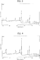
- FIG. 3 is a graph showing an XPS wide spectrum of the outermost surface of the insulating coating B.
- FIG. 4 is a graph showing an XPS wide spectrum of the surface of the insulating coating B that is exposed by scraping by 50 nm in the depth direction from the outermost surface.
- the presence of Cr was observed not only at a depth of 50 nm from the outermost surface but also in the outermost surface.
- the XPS spectrum in FIG. 3 shows a Cr2p 1/2 peak (represented by "Cr(2p1)” in FIG. 3 ) and a Cr2p 3/2 peak (represented by "Cr(2p3)” in FIG. 3 ).
- the insulating coating A above corresponds to an insulating coating formed by any of the methods disclosed in, for instance, Patent Literatures 1 and 2.
- Cr is not present in the outermost surface or, even if present, is not bonded with another element. This is probably the reason why the viscosity remains low at high temperature and sticking easily occurs.
- the grain oriented electrical steel sheet with an insulating coating according to the invention includes a grain oriented electrical steel sheet; and an insulating coating provided on a surface of the grain oriented electrical steel sheet, wherein the insulating coating contains at least one selected from the group consisting of Mg, Ca, Ba, Sr, Zn, Al and Mn, and Si, P, O and Cr, and wherein the insulating coating has an outermost surface that exhibits an XPS spectrum showing a Cr2p 1/2 peak and a Cr2p 3/2 peak.
- the grain oriented electrical steel sheet is not particularly limited but a conventionally known grain oriented electrical steel sheet may be used.
- the grain oriented electrical steel sheet is usually manufactured by a process which involves performing hot rolling of a silicon-containing steel slab by means of a known method, performing one cold rolling step or a plurality of cold rolling steps including intermediate annealing to finish the steel slab to a final thickness, thereafter performing primary recrystallization annealing, then applying an annealing separator, and performing final finishing annealing.
- the presence of elements contained in the insulating coating can be determined by XPS analysis.
- the insulating coating according to the invention which corresponds to the insulating coating B described above, has the XPS spectra showing Mg2s, Mg2p, P2s, P2p, O2s and other peaks ( FIGS. 3 and 4 ). This reveals that the insulating coating contains, in addition to Cr, at least Mg, Si, P and O.
- an insulating coating formed using a treatment solution containing a phosphate of at least one selected from the group consisting of Mg, Ca, Ba, Sr, Zn, Al and Mn, colloidal silica, and a Cr compound is deemed to contain at least one selected from the group consisting of Mg, Ca, Ba, Sr, Zn, Al and Mn, and Si, P, O and Cr.
- the insulating coating according to the invention has the outermost surface that exhibits the XPS spectrum showing a Cr2p 1/2 peak and a Cr2p 3/2 peak (see FIG. 3 ). This represents excellent heat resistance.
- manufacturing method of the invention that is for obtaining the steel sheet of the invention is described as follows.
- the first method is a method of manufacturing the grain oriented electrical steel sheet with an insulating coating according to the invention, the grain oriented electrical steel sheet with an insulating coating being obtained by performing baking after applying a treatment solution to a surface of a grain oriented electrical steel sheet having undergone finishing annealing, wherein the treatment solution contains a phosphate of at least one selected from the group consisting of Mg, Ca, Ba, Sr, Zn, Al and Mn, colloidal silica, and a Cr compound, wherein a colloidal silica content in the treatment solution in terms of solid content is 50 to 150 parts by mass with respect to 100 parts by mass of total solids in the phosphate, wherein a Cr compound content in the treatment solution in terms of CrO 3 is 10 to 50 parts by mass with respect to 100 parts by mass of total solids in the phosphate, and wherein conditions of the baking in which a baking temperature T (unit: °C) ranges 850 ⁇ T ⁇ 1000, a hydrogen concentration H 2 (unit: vol%) in
- the treatment solution is a treatment solution for forming the insulating coating that contains at least a phosphate of at least one selected from the group consisting of Mg, Ca, Ba, Sr, Zn, Al and Mn, colloidal silica, and a Cr compound.
- the metal species of the phosphate is not particularly limited as long as at least one selected from the group consisting of Mg, Ca, Ba, Sr, Zn, Al and Mn is used.
- Phosphates of alkali metals e.g., Li and Na
- Li and Na are significantly inferior in heat resistance and moisture absorption resistance of a resulting insulating coating and hence inappropriate.
- the phosphates may be used singly or in combination of two or more. Physical property values of the resulting insulating coating can be precisely controlled by using two or more phosphates in combination.
- a primary phosphate (biphosphate) is advantageously used as such a phosphate from the viewpoint of availability.
- the colloidal silica preferably has an average particle size of 5 to 200 nm, and more preferably 10 to 100 nm from the viewpoint of availability and costs.
- the average particle size of the colloidal silica can be measured by the BET method (in terms of specific surface area obtained using an adsorption method). It is also possible to use instead an average value of actual measurement values on an electron micrograph.
- the colloidal silica content in the treatment solution in terms of SiO 2 solid content is 50 to 150 parts by mass and preferably 50 to 100 parts by mass with respect to 100 parts by mass of total solids in the phosphate.
- Too low a colloidal silica content may impair the effect of reducing the coefficient of thermal expansion of the insulating coating, thus reducing the tension to be applied to the steel sheet.
- too high a colloidal silica content may cause crystallization of the insulating coating to proceed easily at the time of baking to be described later, thus also reducing the tension to be applied to the steel sheet.
- the insulating coating imparts a proper tension to the steel sheet and is highly effective in improving the iron loss.
- An exemplary Cr compound contained in the treatment solution is a chromic acid compound, a specific example of which is at least one selected from the group consisting of chromic anhydride (CrO 3 ), a chromate and a bichromate.
- metal species of chromates and bichromates include Na, K, Mg, Ca, Mn, Mo, Zn and Al.
- chromic anhydride (CrO 3 ) is preferred for the Cr compound.
- the Cr compound content in the treatment solution in terms of CrO 3 is 10 to 50 parts by mass and preferably 15 to 35 parts by mass with respect to 100 parts by mass of total solids in the phosphate.
- the insulating coating has sufficient heat resistance and is also favorable from the viewpoint of influence on a human body.
- the method of applying the above-described treatment solution to the surface of the grain oriented electrical steel sheet is not particularly limited but a conventionally known method may be used.
- the treatment solution is preferably applied to both surfaces of the steel sheet and more preferably applied so that the coating amount on both the surfaces after baking becomes 4 to 15 g/m 2 .
- the interlaminar insulation resistance may be reduced when the coating amount is too small, whereas the lamination factor may be more reduced when the coating amount is too large.
- the treatment solution is preferably sufficiently dried before baking and the grain oriented electrical steel sheet having the treatment solution applied thereto is more preferably dried (subjected to preliminary baking) before baking from the viewpoint of preventing poor film formation due to abrupt heating and also from the viewpoint that controlling the phosphate bonding state through reduction treatment of the insulating coating during baking, which is one characteristic feature of the invention, is stably performed.
- a steel sheet having the treatment solution applied thereto is preferably placed in a drying furnace and retained for drying at 150 to 450°C for 10 seconds or more.
- drying may not be enough to obtain a desired binding state, and at a temperature higher than 450°C, the steel sheet may be oxidized during drying. In contrast, under conditions of 150 to 450°C and 10 seconds or more, the steel sheet can be adequately dried while suppressing its oxidation.
- a longer drying time is preferred but a drying time of 120 seconds or less is preferred because the productivity is easily reduced when the drying time exceeds 120 seconds.
- the grain oriented electrical steel sheet dried after application of the treatment solution is baked to form the insulating coating.
- the insulating coating needs to have the outermost surface that exhibits an XPS spectrum showing a Cr2p 1/2 peak and a Cr2p 3/2 peak.
- the method of forming such an insulating coating is not particularly limited, and an exemplary method for obtaining the above-described XPS spectrum only needs to include specific conditions for baking.
- the conditions should include 1) a higher baking temperature (hereinafter denoted by "T"), 2) a higher hydrogen concentration (hereinafter denoted by "H 2 ”) in the baking atmosphere, and 3) a longer baking time (hereinafter denoted by "Time”) at the baking temperature T.
- the baking temperature T (unit: °C) is set in the range of 850 ⁇ T ⁇ 1000.
- the baking temperature (T) is set to 850°C or more so that the XPS spectrum of the outermost surface of the insulating coating shows a Cr2p 1/2 peak and a Cr2p 3/2 peak.
- the baking temperature is set to 1000°C or less.
- the hydrogen concentration H 2 (unit: vol%) in the baking atmosphere is set in the range of 0.3 ⁇ H 2 ⁇ 230 - 0.2T.
- the hydrogen concentration (H 2 ) is set to 0.3 vol% or more so that the XPS spectrum of the outermost surface of the insulating coating shows a Cr2p 1/2 peak and a Cr2p 3/2 peak.
- the limit concentration is related to the baking temperature (T) and is set in the range of H 2 ⁇ 230-0.2T.
- the remainder of the baking atmosphere except hydrogen is preferably an inert gas, and more preferably nitrogen.
- the baking time Time (unit: s) is set in the range of 5 ⁇ Time ⁇ 860 - 0.8T.
- the baking time (Time) is set to 5 seconds or more so that the XPS spectrum of the outermost surface of the insulating coating shows a Cr2p 1/2 peak and a Cr2p 3/2 peak.
- the limit time is related to the baking temperature (T) and is set in the range of Time ⁇ 860 - 0.8T.
- the second method of the manufacturing method of the invention is a method of manufacturing the grain oriented electrical steel sheet with an insulating coating according to claim 1, the grain oriented electrical steel sheet with an insulating coating being obtained by performing baking and plasma treatment in this order after applying a treatment solution to a surface of a grain oriented electrical steel sheet having undergone finishing annealing, wherein the treatment solution contains a phosphate of at least one selected from the group consisting of Mg, Ca, Ba, Sr, Zn, Al and Mn, colloidal silica, and a Cr compound, wherein a colloidal silica content in the treatment solution in terms of solid content is 50 to 150 parts by mass with respect to 100 parts by mass of total solids in the phosphate, wherein a Cr compound content in the treatment solution in terms of CrO 3 is 10 to 50 parts by mass with respect to 100 parts by mass of total solids in the phosphate, wherein conditions of the baking in which a baking temperature T (unit: °C) ranges 800 ⁇ T ⁇ 1000,
- the baking temperature T (unit: °C) can also be set in a wider range than under the conditions in the first method (850 ⁇ T ⁇ 1000), and is in the range of 800 ⁇ T ⁇ 1000 in the second method.
- the baking time Time (unit: s) at the baking temperature T is set in the range of Time ⁇ 300.
- an insulating coating having the outermost surface that exhibits an XPS spectrum showing a Cr2p 1/2 peak and a Cr2p 3/2 peak and thus having excellent heat resistance is obtained by further performing specific plasma treatment.
- a surface of the grain oriented electrical steel sheet after the baking is irradiated with plasma generated from plasma gas containing at least 0.3 vol% of hydrogen for 0.10 seconds or more.
- Plasma treatment is often performed in a vacuum, and vacuum plasma can be suitably used also in the present invention.
- the plasma treatment is not limited to this but, for example, atmospheric pressure plasma can also be used.
- the atmospheric pressure plasma is plasma generated under atmospheric pressure.
- the "atmospheric pressure" as used herein may be a pressure close to the atmospheric pressure, as exemplified by a pressure of 1.0 x 10 4 to 1.5 x 10 5 Pa.
- a radio frequency voltage is applied between opposed electrodes in the plasma gas (working gas) under atmospheric pressure to cause discharge to thereby generate plasma, and the surface of the steel sheet is irradiated with the plasma.
- the plasma gas (working gas) is required to contain at least 0.3 vol% of hydrogen.
- the hydrogen concentration is less than 0.3 vol%, excellent heat resistance is not obtained even after plasma treatment.
- the upper limit of the hydrogen concentration in the plasma gas is not particularly limited, and is preferably 50 vol% or less and more preferably 10 vol% or less.
- the gaseous remainder of the plasma gas except hydrogen preferably includes helium and argon because of easy plasma generation.
- Plasma treatment is preferably performed after the temperature of the baked steel sheet dropped to 100°C or less. In other words, it is preferable to irradiate the surface of the baked steel sheet whose temperature dropped to 100°C or less with plasma. When the temperature is too high, the plasma generating portion may have a high temperature and this highly possibly causes a defect, but the defect can be suppressed at 100°C or less.
- the plasma irradiation time is set to 0.10 seconds or more because a beneficial effect is not obtained when the plasma irradiation time is too short. On the other hand, too long a plasma irradiation time does not cause a problem on the properties of the insulating coating, but the upper limit of the irradiation time is preferably 10 seconds or less from the viewpoint of productivity.
- the plasma gas temperature (exit temperature) is preferably 200°C or less, and more preferably 150°C or less from the viewpoint that no thermal strain is applied to the steel sheet.
- a grain oriented electrical steel sheet with a sheet thickness of 0.23 mm (magnetic flux density B 8 : 1.912 T) that had undergone finishing annealing was prepared.
- the steel sheet was cut into a size of 100 mm x 300 mm and pickled in 5 mass% phosphoric acid.
- a treatment solution prepared by adding 80 parts by mass of colloidal silica (AT-30 manufactured by ADEKA Corporation; average particle size: 10 nm) and 25 parts by mass of chromic anhydride (in terms of CrO 3 ) as a Cr compound with respect to 100 parts by mass of one or more phosphates listed in Table 1 below was applied so that the coating amount on both surfaces after baking became 10 g/m 2 , and the steel sheet was then placed in a drying furnace and dried at 300°C for 1 minute, and thereafter baked under conditions shown in Table 1 below.
- a grain oriented electrical steel sheet with an insulating coating in each example was thus manufactured.
- Each phosphate used was in the form of a primary phosphate aqueous solution, and Table 1 below showed the amounts in terms of solid content.
- the remainder of the baking atmosphere except hydrogen was set to nitrogen.
- the XPS wide spectrum of the outermost surface of an insulating coating was measured by means of SSX-100 manufactured by SSI using AlK ⁇ line as the X-ray source.
- the measured XPS wide spectrum was examined to check whether a Cr2p 1/2 peak and a Cr2p 3/2 peak were present. The results are shown in Table 1 below.
- the grain oriented electrical steel sheet with an insulating coating in each example was sheared into specimens measuring 50 mm x 50 mm, 10 specimens were stacked on top of one another, and annealing under a compressive load of 2 kg/cm 2 was performed in a nitrogen atmosphere at 830°C for 3 hours. Then, a weight of 500 g was dropped from heights of 20 to 120 cm at intervals of 20 cm to evaluate the heat resistance of the insulating coating based on the height of the weight (drop height) at which the 10 specimens were all separated from each other. In a case in which the 10 specimens were all separated from each other after the annealing under compressive loading but before the drop weight test, the drop height was set to 0 cm. When the specimens were separated from each other at a drop height of 40 cm or less, the insulating coating was rated as having excellent heat resistance. The results are shown in Table 1 below.
- the lamination factor of the grain oriented electrical steel sheet with an insulating coating in each example was determined according to JIS C 2550-5:2011. As a result, in every example, the insulating coating did not contain oxide fine particles or the like, and the lamination factor was therefore as good as 97.8% or more.
- the rate of rusting of the grain oriented electrical steel sheet with an insulating coating in each example was determined after exposing the steel sheet to an atmosphere of 40°C and 100% humidity for 50 hours. As a result, in every example, the rate of rusting was 1% or less, and the corrosion resistance was good.
- a grain oriented electrical steel sheet with a sheet thickness of 0.23 mm (magnetic flux density B 8 : 1.912 T) that had undergone finishing annealing was prepared.
- the steel sheet was cut into a size of 100 mm x 300 mm and pickled in 5 mass% phosphoric acid.
- a treatment solution prepared by adding 60 parts by mass of colloidal silica (SNOWTEX 50 manufactured by Nissan Chemical Industries, Ltd.; average particle size: 30 nm) and 30 parts by mass of chromic anhydride (in terms of CrO 3 ) as a Cr compound with respect to 100 parts by mass of one or more phosphates listed in Table 2 below was applied so that the coating amount on both surfaces after baking became 10 g/m 2 , and the steel sheet was then placed in a drying furnace and dried at 300°C for 1 minute, and thereafter subjected to baking and plasma treatment under conditions shown in Table 2 below.
- a grain oriented electrical steel sheet with an insulating coating in each example was thus manufactured.
- Each phosphate used was in the form of a primary phosphate aqueous solution, and Table 2 below showed the amounts in terms of solid content.
- the remainder of the baking atmosphere except hydrogen was set to nitrogen.
- the steel sheet temperature after baking was room temperature.
- the steel sheet was irradiated with atmospheric pressure plasma.
- the atmospheric pressure plasma device used was PF-DFL manufactured by Plasma Factory Co., Ltd., and the plasma head used was a linear plasma head having a width of 300 mm.
- the gas species of the plasma gas included Ar, Ar-N 2 , or Ar-H 2 , and the total flow rate was set to 30 L/min.
- the plasma width was set to 3 mm.
- the plasma head was fixed and the steel sheet conveying speed was varied to vary the irradiation time to thereby uniformly perform plasma treatment on the entire surface of the steel sheet.
- the irradiation time was calculated by dividing the plasma width (3 mm) by the conveyance speed (unit: mm/s).
- the XPS wide spectrum of the outermost surface of an insulating coating in each example was measured by means of SSX-100 manufactured by SSI using AlK ⁇ line as the X-ray source. The measured XPS wide spectrum was examined to check whether a Cr2p 1/2 peak and a Cr2p 3/2 peak were present.
- the grain oriented electrical steel sheet with an insulating coating in each example was sheared into specimens measuring 50 mm x 50 mm, 10 specimens were stacked on top of one another, and annealing under a compressive load of 2 kg/cm 2 was performed in a nitrogen atmosphere at 830°C for 3 hours. Then, a weight of 500 g was dropped from heights of 20 to 120 cm at intervals of 20 cm to evaluate the heat resistance of the insulating coating based on the height of the weight (drop height) at which the 10 specimens were all separated from each other. In a case in which the 10 specimens were all separated from each other after the annealing under compressive loading but before the drop weight test, the drop height was set to 0 cm. When the specimens were separated from each other at a drop height of 40 cm or less, the insulating coating was rated as having excellent heat resistance. The results are shown in Table 2 below.
- the lamination factor of the grain oriented electrical steel sheet with an insulating coating in each example was determined according to JIS C 2550-5:2011. As a result, in every example, the insulating coating did not contain oxide fine particles or the like, and the lamination factor was therefore as good as 97.8% or more.
- the rate of rusting of the grain oriented electrical steel sheet with an insulating coating in each example was determined after exposing the steel sheet to an atmosphere of 40°C and 100% humidity for 50 hours. As a result, in every example, the rate of rusting was 1% or less, and the corrosion resistance was good.
Landscapes
- Chemical & Material Sciences (AREA)
- Engineering & Computer Science (AREA)
- Materials Engineering (AREA)
- Mechanical Engineering (AREA)
- Metallurgy (AREA)
- Organic Chemistry (AREA)
- General Chemical & Material Sciences (AREA)
- Chemical Kinetics & Catalysis (AREA)
- Physics & Mathematics (AREA)
- Thermal Sciences (AREA)
- Crystallography & Structural Chemistry (AREA)
- Power Engineering (AREA)
- Electromagnetism (AREA)
- Manufacturing & Machinery (AREA)
- Chemical Treatment Of Metals (AREA)
- Manufacturing Of Steel Electrode Plates (AREA)
Description
- The present invention relates to a method of manufacturing a grain oriented electrical steel sheet with an insulating coating.
- In general, a grain oriented electrical steel sheet (hereinafter also referred to simply as "steel sheet") is provided with a coating on its surface to impart insulation properties, workability, corrosion resistance and other properties. Such a surface coating includes an undercoating primarily composed of forsterite and formed in final finishing annealing, and a phosphate-based top coating formed on the undercoating.
- Of the coatings formed on the surface of the grain oriented electrical steel sheet, only the latter top coating is hereinafter called "insulating coating."
- These coatings are formed at high temperature and further have a low coefficient of thermal expansion, and are therefore effective in imparting tension to the steel sheet owing to a difference in coefficient of thermal expansion between the steel sheet and the coatings when the temperature drops to room temperature, thus reducing iron loss of the steel sheet. Accordingly, the coatings are required to impart the highest possible tension to the steel.
- In order to meet such a requirement, for example, Patent Literatures 1 to 5 disclose insulating coatings each formed using a treatment solution containing a phosphate (e.g., aluminum phosphate, magnesium phosphate), colloidal silica, and chromic anhydride.
- The grain oriented electrical steel sheet with an insulating coating may be hereinafter also simply called "grain oriented electrical steel sheet" or "steel sheet."
-
- Patent Literature 1:
JP 48-39338 A - Patent Literature 2:
JP 50-79442 A - Patent Literature 3:
US 5 961 744 A - Patent Literature 4:
JP H02 4924 A - Patent Literature 5:
WO 2015/040799 A1 - Users of grain oriented electrical steel sheets, and in particular clients manufacturing wound-core transformers perform stress relief annealing at a temperature exceeding 800°C after formation of cores for wound-core transformers through lamination of steel sheets to thereby release stress generated in the formation of the cores, thus eliminating deterioration of magnetic properties.
- In this step, when the insulating coating is low in heat resistance, laminated steel sheets may stick to each other to lower the workability in the subsequent step. Sticking may also deteriorate magnetic properties.
- The inventors of the present invention have studied the insulating coatings disclosed in Patent Literatures 1 and 2 and as a result found that sticking may not be adequately suppressed due to insufficient heat resistance.
- The present invention has been made in view of the above and aims at providing a method of manufacturing a grain oriented electrical steel sheet with a highly heat-resistant insulating coating.
- The inventors of the present invention have made an intensive study to achieve the above-described object and as a result found that whether Cr bonded to another element is present at the outermost surface of an insulating coating has an influence on the level of heat resistance of the insulating coating, and also found a technique for making Cr bonded to another element be present at the outermost surface of the insulating coating. The present invention has been thus completed.
- Specifically, the present invention is defined by the claims.
- The present invention has been made in view of the above and aims at providing a grain oriented electrical steel sheet with an insulating coating having a highly heat-resistant insulating coating, and a method of manufacturing the same.
-
- [
FIG. 1] FIG. 1 is a graph showing an XPS wide spectrum of the outermost surface of an insulating coating A. - [
FIG. 2] FIG. 2 is a graph showing an XPS wide spectrum of the surface of the insulating coating A that is exposed by scraping by 50 nm in the depth direction from the outermost surface. - [
FIG. 3] FIG. 3 is a graph showing an XPS wide spectrum of the outermost surface of an insulating coating B. - [
FIG. 4] FIG. 4 is a graph showing an XPS wide spectrum of the surface of the insulating coating B that is exposed by scraping by 50 nm in the depth direction from the outermost surface. - Findings from XPS analysis that have led the inventors to complete the present invention are first described.
- A grain oriented electrical steel sheet that had been manufactured by a known method, had a sheet thickness of 0.23 mm, and had undergone finishing annealing was sheared to a size of 300 mm x 100 mm, and an unreacted annealing separator was removed. Thereafter, stress relief annealing (800°C, 2 hours, N2 atmosphere) was performed.
- Next, a treatment solution for insulating coating formation was applied to the steel sheet that had been slightly pickled in 5 mass% phosphoric acid. The treatment solution contained 100 parts by mass (in terms of solid content) of an aluminum primary phosphate aqueous solution, 80 parts by mass (in terms of solid content) of colloidal silica and 25 parts by mass (in terms of CrO3) of a Cr compound, and the treatment solution was applied so that the coating amount on both surfaces after baking became 10 g/m2.
- The steel sheet to which the treatment solution had been applied was placed in a drying furnace, dried at 300°C for 1 minute, and then baked at 850°C for 1 minute in a 100% N2 atmosphere, thereby obtaining a grain oriented electrical steel sheet with an insulating coating. For the sake of convenience, an insulating coating of the resulting steel sheet may also be referred to as "insulating coating A."
- Next, the heat resistance of the insulating coating A was evaluated by a drop weight test. Specifically, each resulting steel sheet was sheared into specimens measuring 50 mm x 50 mm, 10 specimens were stacked on top of one another, and annealing under a compressive load of 2 kg/cm2 was performed in a nitrogen atmosphere at 830°C for 3 hours. Then, a weight of 500 g was dropped from heights of 20 to 120 cm at intervals of 20 cm to evaluate the heat resistance of the insulating coating based on the height of the weight (drop height) at which the 10 specimens were all separated from each other. In a case in which the 10 specimens were all separated from each other after the annealing under compressive loading but before the drop weight test, the drop height was set to 0 cm.
- When the specimens were separated from each other at a drop height of 40 cm or less, the insulating coating was rated as having excellent heat resistance. The insulating coating A showed a drop height of 100 cm and thus had poor heat resistance.
- Subsequently, similarly to the case of the insulating coating A, a treatment solution for insulating coating formation was applied to the steel sheet that had been slightly pickled in 5 mass% phosphoric acid. The treatment solution contained 100 parts by mass (in terms of solid content) of a magnesium primary phosphate aqueous solution, 80 parts by mass (in terms of solid content) of colloidal silica and 25 parts by mass (in terms of CrO3) of chromic anhydride as a Cr compound, and the treatment solution was applied so that the coating amount on both surfaces after baking became 10 g/m2.
- The steel sheet to which the treatment solution had been applied was placed in a drying furnace, dried at 300°C for 1 minute, and then baked at 900°C for 30 seconds in an atmosphere with a hydrogen concentration of 5 vol% (with the remainder being N2), thereby obtaining a grain oriented electrical steel sheet with an insulating coating. For the sake of convenience, an insulating coating of the resulting steel sheet may also be referred to as "insulating coating B."
- The heat resistance of the insulating coating B was evaluated by the drop weight test similarly to the insulating coating A, and it was confirmed that the insulating coating B showed a drop height of 20 cm and exhibited good heat resistance.
- The insulating coating A and the insulating coating B which were thus different in drop height (heat resistance) were intensively studied for differences therebetween, and as a result it was found out that the insulating coatings have different XPS analysis values. This is described below.
- The XPS analysis was performed on the insulating coating A by means of SSX-100 manufactured by SSI using AlKα line as the X-ray source. Specifically, first, the outermost surface of the insulating coating A was subjected to the XPS analysis. Next, the insulating coating A was sputtered with Ar ion beams, and the surface of the insulating coating A that had been exposed by scraping by 50 nm in the depth direction from the outermost surface was subjected to the XPS analysis. Results of the XPS analysis does not depend on the used device.
-
FIG. 1 is a graph showing an XPS wide spectrum of the outermost surface of the insulating coating A.FIG. 2 is a graph showing an XPS wide spectrum of the surface of the insulating coating A that is exposed by scraping by 50 nm in the depth direction from the outermost surface. - As is evident from the graphs shown in
FIGS. 1 and 2 , in the insulating coating A, the presence of Cr was observed at a depth of 50 nm from the outermost surface (seeFIG. 2 ), while the presence of Cr was not observed in the outermost surface (seeFIG. 1 ) despite the fact that the insulating coating A was formed using the treatment solution containing CrO3. - Next, the XPS analysis was performed on the insulating coating B similarly to the insulating coating A.
-
FIG. 3 is a graph showing an XPS wide spectrum of the outermost surface of the insulating coating B.FIG. 4 is a graph showing an XPS wide spectrum of the surface of the insulating coating B that is exposed by scraping by 50 nm in the depth direction from the outermost surface. - As is evident from the graphs shown in
FIGS. 3 and 4 , in the insulating coating B, the presence of Cr was observed not only at a depth of 50 nm from the outermost surface but also in the outermost surface. Specifically, the XPS spectrum inFIG. 3 shows a Cr2p1/2 peak (represented by "Cr(2p1)" inFIG. 3 ) and a Cr2p3/2 peak (represented by "Cr(2p3)" inFIG. 3 ). - The inventors consider the foregoing results as follows.
- The mechanism of heat resistance improvement of an insulating coating formed from a treatment solution containing CrO3 is probably as follows. It is presumed that bonding of Cr with another element strengthens the structure and increases the viscosity of a primarily glassy insulating coating at high temperature, whereby sticking is less likely to occur.
- Meanwhile, the insulating coating A above corresponds to an insulating coating formed by any of the methods disclosed in, for instance, Patent Literatures 1 and 2. In the insulating coating A, Cr is not present in the outermost surface or, even if present, is not bonded with another element. This is probably the reason why the viscosity remains low at high temperature and sticking easily occurs.
- In contrast, in the insulating coating B, Cr is present in the outermost surface and is bonded with another element (probably, mainly O); this is probably the reason why the viscosity increases at high temperature and sticking is less likely to occur.
- Next, a grain oriented electrical steel sheet with an insulating coating according to the invention is described again before also describing its manufacturing method.
- The grain oriented electrical steel sheet with an insulating coating according to the invention (hereinafter also referred to simply as "grain oriented electrical steel sheet of the invention" or "steel sheet of the invention") includes a grain oriented electrical steel sheet; and an insulating coating provided on a surface of the grain oriented electrical steel sheet, wherein the insulating coating contains at least one selected from the group consisting of Mg, Ca, Ba, Sr, Zn, Al and Mn, and Si, P, O and Cr, and wherein the insulating coating has an outermost surface that exhibits an XPS spectrum showing a Cr2p1/2 peak and a Cr2p3/2 peak.
- The grain oriented electrical steel sheet is not particularly limited but a conventionally known grain oriented electrical steel sheet may be used. The grain oriented electrical steel sheet is usually manufactured by a process which involves performing hot rolling of a silicon-containing steel slab by means of a known method, performing one cold rolling step or a plurality of cold rolling steps including intermediate annealing to finish the steel slab to a final thickness, thereafter performing primary recrystallization annealing, then applying an annealing separator, and performing final finishing annealing.
- The presence of elements contained in the insulating coating can be determined by XPS analysis. For example, the insulating coating according to the invention, which corresponds to the insulating coating B described above, has the XPS spectra showing Mg2s, Mg2p, P2s, P2p, O2s and other peaks (
FIGS. 3 and 4 ). This reveals that the insulating coating contains, in addition to Cr, at least Mg, Si, P and O. - According to the invention, an insulating coating formed using a treatment solution containing a phosphate of at least one selected from the group consisting of Mg, Ca, Ba, Sr, Zn, Al and Mn, colloidal silica, and a Cr compound is deemed to contain at least one selected from the group consisting of Mg, Ca, Ba, Sr, Zn, Al and Mn, and Si, P, O and Cr.
- The insulating coating according to the invention has the outermost surface that exhibits the XPS spectrum showing a Cr2p1/2 peak and a Cr2p3/2 peak (see
FIG. 3 ). This represents excellent heat resistance. - Next, a method of manufacturing a grain oriented electrical steel sheet with an insulating coating according to the invention (hereinafter also referred to simply as "manufacturing method of the invention") that is for obtaining the steel sheet of the invention is described as follows.
- First and second manufacturing methods are now described.
- The first method is a method of manufacturing the grain oriented electrical steel sheet with an insulating coating according to the invention, the grain oriented electrical steel sheet with an insulating coating being obtained by performing baking after applying a treatment solution to a surface of a grain oriented electrical steel sheet having undergone finishing annealing, wherein the treatment solution contains a phosphate of at least one selected from the group consisting of Mg, Ca, Ba, Sr, Zn, Al and Mn, colloidal silica, and a Cr compound, wherein a colloidal silica content in the treatment solution in terms of solid content is 50 to 150 parts by mass with respect to 100 parts by mass of total solids in the phosphate, wherein a Cr compound content in the treatment solution in terms of CrO3 is 10 to 50 parts by mass with respect to 100 parts by mass of total solids in the phosphate, and wherein conditions of the baking in which a baking temperature T (unit: °C) ranges 850 ≤ T ≤ 1000, a hydrogen concentration H2 (unit: vol%) in a baking atmosphere ranges 0.3 ≤ H2 ≤ 230 - 0.2T, and a baking time Time (unit: s) at the baking temperature T ranges 5 ≤ Time ≤ 860 - 0.8T are met.
- The treatment solution is a treatment solution for forming the insulating coating that contains at least a phosphate of at least one selected from the group consisting of Mg, Ca, Ba, Sr, Zn, Al and Mn, colloidal silica, and a Cr compound.
- The metal species of the phosphate is not particularly limited as long as at least one selected from the group consisting of Mg, Ca, Ba, Sr, Zn, Al and Mn is used. Phosphates of alkali metals (e.g., Li and Na) are significantly inferior in heat resistance and moisture absorption resistance of a resulting insulating coating and hence inappropriate.
- The phosphates may be used singly or in combination of two or more. Physical property values of the resulting insulating coating can be precisely controlled by using two or more phosphates in combination.
- A primary phosphate (biphosphate) is advantageously used as such a phosphate from the viewpoint of availability.
- The colloidal silica preferably has an average particle size of 5 to 200 nm, and more preferably 10 to 100 nm from the viewpoint of availability and costs. The average particle size of the colloidal silica can be measured by the BET method (in terms of specific surface area obtained using an adsorption method). It is also possible to use instead an average value of actual measurement values on an electron micrograph.
- The colloidal silica content in the treatment solution in terms of SiO2 solid content is 50 to 150 parts by mass and preferably 50 to 100 parts by mass with respect to 100 parts by mass of total solids in the phosphate.
- Too low a colloidal silica content may impair the effect of reducing the coefficient of thermal expansion of the insulating coating, thus reducing the tension to be applied to the steel sheet. On the other hand, too high a colloidal silica content may cause crystallization of the insulating coating to proceed easily at the time of baking to be described later, thus also reducing the tension to be applied to the steel sheet.
- However, when the colloidal silica content is within the above-described range, the insulating coating imparts a proper tension to the steel sheet and is highly effective in improving the iron loss.
- An exemplary Cr compound contained in the treatment solution is a chromic acid compound, a specific example of which is at least one selected from the group consisting of chromic anhydride (CrO3), a chromate and a bichromate.
- Examples of metal species of chromates and bichromates include Na, K, Mg, Ca, Mn, Mo, Zn and Al.
- Of these, chromic anhydride (CrO3) is preferred for the Cr compound.
- The Cr compound content in the treatment solution in terms of CrO3 is 10 to 50 parts by mass and preferably 15 to 35 parts by mass with respect to 100 parts by mass of total solids in the phosphate.
- When the Cr compound content is too low, sufficient heat resistance may not be obtained. On the other hand, when the Cr compound content is too high, a part of Cr atoms may become hexavalent chromium, which may not be favorable from the viewpoint of influence on a human body.
- However, when the Cr compound content is within the above-described range, the insulating coating has sufficient heat resistance and is also favorable from the viewpoint of influence on a human body.
- The method of applying the above-described treatment solution to the surface of the grain oriented electrical steel sheet is not particularly limited but a conventionally known method may be used.
- The treatment solution is preferably applied to both surfaces of the steel sheet and more preferably applied so that the coating amount on both the surfaces after baking becomes 4 to 15 g/m2. The interlaminar insulation resistance may be reduced when the coating amount is too small, whereas the lamination factor may be more reduced when the coating amount is too large.
- Since moisture dries in the temperature elevation process during baking, drying may not be separately performed before baking. However, the treatment solution is preferably sufficiently dried before baking and the grain oriented electrical steel sheet having the treatment solution applied thereto is more preferably dried (subjected to preliminary baking) before baking from the viewpoint of preventing poor film formation due to abrupt heating and also from the viewpoint that controlling the phosphate bonding state through reduction treatment of the insulating coating during baking, which is one characteristic feature of the invention, is stably performed.
- To be more specific, for example, a steel sheet having the treatment solution applied thereto is preferably placed in a drying furnace and retained for drying at 150 to 450°C for 10 seconds or more.
- Under conditions of less than 150°C and/or less than 10 seconds, drying may not be enough to obtain a desired binding state, and at a temperature higher than 450°C, the steel sheet may be oxidized during drying. In contrast, under conditions of 150 to 450°C and 10 seconds or more, the steel sheet can be adequately dried while suppressing its oxidation.
- A longer drying time is preferred but a drying time of 120 seconds or less is preferred because the productivity is easily reduced when the drying time exceeds 120 seconds.
- Next, the grain oriented electrical steel sheet dried after application of the treatment solution is baked to form the insulating coating.
- As described above, in order to obtain an insulating coating having excellent heat resistance, the insulating coating needs to have the outermost surface that exhibits an XPS spectrum showing a Cr2p1/2 peak and a Cr2p3/2 peak. The method of forming such an insulating coating is not particularly limited, and an exemplary method for obtaining the above-described XPS spectrum only needs to include specific conditions for baking. To be more specific, the conditions should include 1) a higher baking temperature (hereinafter denoted by "T"), 2) a higher hydrogen concentration (hereinafter denoted by "H2") in the baking atmosphere, and 3) a longer baking time (hereinafter denoted by "Time") at the baking temperature T.
- The respective conditions are described below in further detail.
- The baking temperature T (unit: °C) is set in the range of 850 ≤ T ≤ 1000. The baking temperature (T) is set to 850°C or more so that the XPS spectrum of the outermost surface of the insulating coating shows a Cr2p1/2 peak and a Cr2p3/2 peak. On the other hand, when the baking temperature (T) is too high, crystallization of the primarily glassy insulating coating proceeds excessively to reduce the tension to be applied to the steel sheet. Therefore, the baking temperature is set to 1000°C or less.
- The hydrogen concentration H2 (unit: vol%) in the baking atmosphere is set in the range of 0.3 ≤ H2 ≤ 230 - 0.2T. The hydrogen concentration (H2) is set to 0.3 vol% or more so that the XPS spectrum of the outermost surface of the insulating coating shows a Cr2p1/2 peak and a Cr2p3/2 peak. On the other hand, when the hydrogen concentration (H2) is too high, crystallization of the primarily glassy insulating coating proceeds excessively. The limit concentration is related to the baking temperature (T) and is set in the range of H2 ≤ 230-0.2T.
- The remainder of the baking atmosphere except hydrogen is preferably an inert gas, and more preferably nitrogen.
- The baking time Time (unit: s) is set in the range of 5 ≤ Time ≤ 860 - 0.8T. The baking time (Time) is set to 5 seconds or more so that the XPS spectrum of the outermost surface of the insulating coating shows a Cr2p1/2 peak and a Cr2p3/2 peak. On the other hand, when the baking time (Time) is too long, again, crystallization of the insulating coating proceeds excessively. The limit time is related to the baking temperature (T) and is set in the range of Time ≤ 860 - 0.8T.
- Next, the manufacturing method of the invention is described with reference to the second method.
- In the foregoing first method, a description was given of the specific baking conditions for forming, as an insulating coating having excellent heat resistance, the insulating coating having the outermost surface that exhibits an XPS spectrum showing a Cr2p1/2 peak and a Cr2p3/2 peak. However, even when the baking conditions in the first method are not met, for example, for lack of the hydrogen concentration H2, the same insulating coating as in the first method is obtained by further performing plasma treatment under specific conditions.
- More specifically, the second method of the manufacturing method of the invention is a method of manufacturing the grain oriented electrical steel sheet with an insulating coating according to claim 1, the grain oriented electrical steel sheet with an insulating coating being obtained by performing baking and plasma treatment in this order after applying a treatment solution to a surface of a grain oriented electrical steel sheet having undergone finishing annealing, wherein the treatment solution contains a phosphate of at least one selected from the group consisting of Mg, Ca, Ba, Sr, Zn, Al and Mn, colloidal silica, and a Cr compound, wherein a colloidal silica content in the treatment solution in terms of solid content is 50 to 150 parts by mass with respect to 100 parts by mass of total solids in the phosphate, wherein a Cr compound content in the treatment solution in terms of CrO3 is 10 to 50 parts by mass with respect to 100 parts by mass of total solids in the phosphate, wherein conditions of the baking in which a baking temperature T (unit: °C) ranges 800 ≤ T ≤ 1000, a hydrogen concentration H2 (unit: vol%) in a baking atmosphere ranges 0 ≤ H2 ≤ 230 - 0.2T, and a baking time Time (unit: s) at the baking temperature T ranges Time ≤ 300 are met, and wherein the plasma treatment is a treatment which includes irradiating the surface of the grain oriented electrical steel sheet after the baking with plasma generated from plasma gas containing at least 0.3 vol% of hydrogen for 0.10 seconds or more.
- Since conditions (treatment solution used, application method, and drying method) in the second method are the same as those in the first method except for baking and plasma treatment, their description is omitted.
- In the second method, it is found that plasma treatment is performed as the remedial treatment in the case where desired performance is not obtained, and acceptable ranges of the baking conditions are wider than those in the first method. Even if the steel sheet obtained in the first method of the manufacturing method of the invention is further subjected to plasma treatment, good performance is not impaired.
- Specifically, as for the hydrogen concentration H2 (unit: vol%) in the baking atmosphere, 0.3 ≤ H2 ≤ 230 - 0.2T is met in the first method but 0 ≤ H2 ≤ 230 - 0.2T is set in the second method. Good performance can be obtained even in the case of 0 ≤ H2 < 0.3 in which desired properties were not obtained according to the first method.
- The baking temperature T (unit: °C) can also be set in a wider range than under the conditions in the first method (850 ≤ T ≤ 1000), and is in the range of 800 ≤ T ≤ 1000 in the second method. In addition, the baking time Time (unit: s) at the baking temperature T is set in the range of Time ≤ 300.
- As described above, even if the baking conditions do not meet the conditions in the first method, an insulating coating having the outermost surface that exhibits an XPS spectrum showing a Cr2p1/2 peak and a Cr2p3/2 peak and thus having excellent heat resistance is obtained by further performing specific plasma treatment.
- To be more specific, a surface of the grain oriented electrical steel sheet after the baking is irradiated with plasma generated from plasma gas containing at least 0.3 vol% of hydrogen for 0.10 seconds or more.
- Plasma treatment is often performed in a vacuum, and vacuum plasma can be suitably used also in the present invention. However, the plasma treatment is not limited to this but, for example, atmospheric pressure plasma can also be used. Now simply referring to the atmospheric pressure plasma, the atmospheric pressure plasma is plasma generated under atmospheric pressure. The "atmospheric pressure" as used herein may be a pressure close to the atmospheric pressure, as exemplified by a pressure of 1.0 x 10⁴ to 1.5 x 10⁵ Pa.
- For example, a radio frequency voltage is applied between opposed electrodes in the plasma gas (working gas) under atmospheric pressure to cause discharge to thereby generate plasma, and the surface of the steel sheet is irradiated with the plasma.
- In this step, the plasma gas (working gas) is required to contain at least 0.3 vol% of hydrogen. When the hydrogen concentration is less than 0.3 vol%, excellent heat resistance is not obtained even after plasma treatment.
- The upper limit of the hydrogen concentration in the plasma gas is not particularly limited, and is preferably 50 vol% or less and more preferably 10 vol% or less.
- The gaseous remainder of the plasma gas except hydrogen preferably includes helium and argon because of easy plasma generation.
- Plasma treatment is preferably performed after the temperature of the baked steel sheet dropped to 100°C or less. In other words, it is preferable to irradiate the surface of the baked steel sheet whose temperature dropped to 100°C or less with plasma. When the temperature is too high, the plasma generating portion may have a high temperature and this highly possibly causes a defect, but the defect can be suppressed at 100°C or less.
- The plasma irradiation time is set to 0.10 seconds or more because a beneficial effect is not obtained when the plasma irradiation time is too short. On the other hand, too long a plasma irradiation time does not cause a problem on the properties of the insulating coating, but the upper limit of the irradiation time is preferably 10 seconds or less from the viewpoint of productivity.
- The plasma gas temperature (exit temperature) is preferably 200°C or less, and more preferably 150°C or less from the viewpoint that no thermal strain is applied to the steel sheet.
- The present invention is specifically described below by way of examples. However, the present invention is not limited thereto.
- A grain oriented electrical steel sheet with a sheet thickness of 0.23 mm (magnetic flux density B8: 1.912 T) that had undergone finishing annealing was prepared. The steel sheet was cut into a size of 100 mm x 300 mm and pickled in 5 mass% phosphoric acid. Then, a treatment solution prepared by adding 80 parts by mass of colloidal silica (AT-30 manufactured by ADEKA Corporation; average particle size: 10 nm) and 25 parts by mass of chromic anhydride (in terms of CrO3) as a Cr compound with respect to 100 parts by mass of one or more phosphates listed in Table 1 below was applied so that the coating amount on both surfaces after baking became 10 g/m2, and the steel sheet was then placed in a drying furnace and dried at 300°C for 1 minute, and thereafter baked under conditions shown in Table 1 below. A grain oriented electrical steel sheet with an insulating coating in each example was thus manufactured.
- Each phosphate used was in the form of a primary phosphate aqueous solution, and Table 1 below showed the amounts in terms of solid content. The remainder of the baking atmosphere except hydrogen was set to nitrogen.
- In each example, the amount of change (ΔW) of iron loss was determined by an expression shown below. The results are shown in Table 1 below.

- ▪ W17/50(C): iron loss immediately after baking
- ▪ W17/50(R): iron loss immediately before applying the treatment solution (0.840 W/kg)
- For the grain oriented electrical steel sheet with an insulating coating in each example, the XPS wide spectrum of the outermost surface of an insulating coating was measured by means of SSX-100 manufactured by SSI using AlKα line as the X-ray source. The measured XPS wide spectrum was examined to check whether a Cr2p1/2 peak and a Cr2p3/2 peak were present. The results are shown in Table 1 below.
- The grain oriented electrical steel sheet with an insulating coating in each example was sheared into specimens measuring 50 mm x 50 mm, 10 specimens were stacked on top of one another, and annealing under a compressive load of 2 kg/cm2 was performed in a nitrogen atmosphere at 830°C for 3 hours. Then, a weight of 500 g was dropped from heights of 20 to 120 cm at intervals of 20 cm to evaluate the heat resistance of the insulating coating based on the height of the weight (drop height) at which the 10 specimens were all separated from each other. In a case in which the 10 specimens were all separated from each other after the annealing under compressive loading but before the drop weight test, the drop height was set to 0 cm. When the specimens were separated from each other at a drop height of 40 cm or less, the insulating coating was rated as having excellent heat resistance. The results are shown in Table 1 below.
- The lamination factor of the grain oriented electrical steel sheet with an insulating coating in each example was determined according to JIS C 2550-5:2011. As a result, in every example, the insulating coating did not contain oxide fine particles or the like, and the lamination factor was therefore as good as 97.8% or more.
- The rate of rusting of the grain oriented electrical steel sheet with an insulating coating in each example was determined after exposing the steel sheet to an atmosphere of 40°C and 100% humidity for 50 hours. As a result, in every example, the rate of rusting was 1% or less, and the corrosion resistance was good.
-
Table 1 No. Phosphate [parts by mass] (in terms of solid content) Baking condition ΔW [W/kg] Cr peak Drop height [cm] Remarks Magnesium phosphate Calcium phosphate Barium phosphate Strontium ph ophate Zinc phosphate Aluminum phosphate Manganese phosphate T [°C] H2 [vol%] 230-0.2T Time [s] 860-0.8T 2p1/2 2p3/2 1 100 800 0.3 70 30 220 -0.022 Absent Absent 120 CE 2 100 850 0.0 60 30 180 -0.031 Absent Absent 100 CE 3 100 850 0.3 60 3 180 -0.028 Absent Absent 80 CE 4 100 850 0.3 60 5 180 -0.029 Present Present 40 RE 5 100 850 0.0 60 180 180 -0.019 Absent Absent 100 CE 6 100 850 0.3 60 30 180 -0.022 Present Present 40 RE 7 100 900 0.3 50 5 140 -0.028 Present Present 20 RE 8 100 900 0.3 50 30 140 -0.035 Present Present 20 RE 9 100 900 5.0 50 30 140 -0.028 Present Present 0 RE 10 100 850 20.0 60 30 180 -0.029 Present Present 20 RE 11 100 850 60.0 60 30 180 -0.035 Present Present 0 RE 12 100 900 10.0 50 30 140 -0.028 Present Present 0 RE 13 100 900 50.0 50 30 140 -0.028 Present Present 0 RE 14 100 800 30.0 70 30 220 -0.035 Absent Absent 100 CE 15 100 900 0.0 50 30 140 -0.032 Absent Absent 80 CE 16 100 900 40.0 50 30 140 -0.033 Present Present 40 RE 17 100 900 40.0 50 5 140 -0.028 Present Present 40 RE 18 100 950 20.0 40 30 100 -0.032 Present Present 20 RE 19 100 950 40.0 40 30 100 -0.032 Present Present 20 RE 20 100 1000 0.0 30 30 60 -0.025 Absent Absent 60 CE 21 100 1000 30.0 30 2 60 -0.026 Absent Absent 60 CE 22 100 1000 30.0 30 5 60 -0.028 Present Present 40 RE 23 100 1000 30.0 30 30 60 -0.029 Present Present 20 RE 24 40 60 850 5.0 60 180 180 -0.018 Present Present 20 RE 25 50 50 850 40.0 60 20 180 -0.029 Present Present 20 RE 26 100 900 20.0 50 10 140 -0.028 Present Present 40 RE 27 100 900 10.0 50 140 140 -0.019 Present Present 20 RE 28 100 950 0.0 40 10 100 -0.032 Absent Absent 100 CE 29 70 30 950 5.0 40 100 100 -0.028 Present Present 20 RE 30 80 20 1000 0.3 30 60 60 -0.018 Present Present 40 RE 31 50 50 1000 5.0 30 30 60 -0.028 Present Present 20 RE 32 50 50 900 5.0 50 10 140 -0.032 Present Present 40 RE 33 50 50 900 5.0 50 30 140 -0.035 Present Present 20 RE 34 60 40 900 5.0 50 60 140 -0.032 Present Present 20 RE CE: Comparative Example
IE: Inventive Example
RE: Reference Example - As shown in Table 1 above, it was revealed that the insulating films in the Examples in each of which the XPS spectrum shows a Cr2p1/2 peak and a Cr2p3/2 peak have excellent heat resistance.
- A grain oriented electrical steel sheet with a sheet thickness of 0.23 mm (magnetic flux density B8: 1.912 T) that had undergone finishing annealing was prepared. The steel sheet was cut into a size of 100 mm x 300 mm and pickled in 5 mass% phosphoric acid. Then, a treatment solution prepared by adding 60 parts by mass of colloidal silica (SNOWTEX 50 manufactured by Nissan Chemical Industries, Ltd.; average particle size: 30 nm) and 30 parts by mass of chromic anhydride (in terms of CrO3) as a Cr compound with respect to 100 parts by mass of one or more phosphates listed in Table 2 below was applied so that the coating amount on both surfaces after baking became 10 g/m2, and the steel sheet was then placed in a drying furnace and dried at 300°C for 1 minute, and thereafter subjected to baking and plasma treatment under conditions shown in Table 2 below. A grain oriented electrical steel sheet with an insulating coating in each example was thus manufactured.
- Each phosphate used was in the form of a primary phosphate aqueous solution, and Table 2 below showed the amounts in terms of solid content. The remainder of the baking atmosphere except hydrogen was set to nitrogen.
- At the beginning of plasma treatment, the steel sheet temperature after baking was room temperature.
- In plasma treatment, the steel sheet was irradiated with atmospheric pressure plasma. The atmospheric pressure plasma device used was PF-DFL manufactured by Plasma Factory Co., Ltd., and the plasma head used was a linear plasma head having a width of 300 mm.
- The gas species of the plasma gas (working gas) included Ar, Ar-N2, or Ar-H2, and the total flow rate was set to 30 L/min.
- The plasma width was set to 3 mm. The plasma head was fixed and the steel sheet conveying speed was varied to vary the irradiation time to thereby uniformly perform plasma treatment on the entire surface of the steel sheet. The irradiation time was calculated by dividing the plasma width (3 mm) by the conveyance speed (unit: mm/s).
- In each example, the amount of change (ΔW) of iron loss was determined by an expression shown below. The results are shown in Table 2 below.

- ▪ W17/50 (P) : iron loss immediately after plasma treatment
- ▪ W17/50 (R) : iron loss immediately before applying the treatment solution (0.840 W/kg)
- The XPS wide spectrum of the outermost surface of an insulating coating in each example was measured by means of SSX-100 manufactured by SSI using AlKα line as the X-ray source. The measured XPS wide spectrum was examined to check whether a Cr2p1/2 peak and a Cr2p3/2 peak were present.
- In each example of Experimental Example 2, measurement was made before and after plasma irradiation in plasma treatment. The results are shown in Table 2 below.
- Since the case where either of the two peaks was solely seen was not observed in any of the measurements, the presence or absence of the peaks is simply stated in Table 2 below without distinguishing the two peaks.
- The grain oriented electrical steel sheet with an insulating coating in each example was sheared into specimens measuring 50 mm x 50 mm, 10 specimens were stacked on top of one another, and annealing under a compressive load of 2 kg/cm2 was performed in a nitrogen atmosphere at 830°C for 3 hours. Then, a weight of 500 g was dropped from heights of 20 to 120 cm at intervals of 20 cm to evaluate the heat resistance of the insulating coating based on the height of the weight (drop height) at which the 10 specimens were all separated from each other. In a case in which the 10 specimens were all separated from each other after the annealing under compressive loading but before the drop weight test, the drop height was set to 0 cm. When the specimens were separated from each other at a drop height of 40 cm or less, the insulating coating was rated as having excellent heat resistance. The results are shown in Table 2 below.
- The lamination factor of the grain oriented electrical steel sheet with an insulating coating in each example was determined according to JIS C 2550-5:2011. As a result, in every example, the insulating coating did not contain oxide fine particles or the like, and the lamination factor was therefore as good as 97.8% or more.
- The rate of rusting of the grain oriented electrical steel sheet with an insulating coating in each example was determined after exposing the steel sheet to an atmosphere of 40°C and 100% humidity for 50 hours. As a result, in every example, the rate of rusting was 1% or less, and the corrosion resistance was good.
-

- As shown in Table 2 above, it was revealed that, even when a Cr2p1/2 peak and a Cr2p3/2 peak did not appear after baking, the two peaks were observed owing to the subsequent plasma treatment, and excellent heat resistance was obtained.
Claims (2)
- A method of manufacturing a grain oriented electrical steel sheet with an insulating coating, comprising:a grain oriented electrical steel sheet; and an insulating coating provided on a surface of the grain oriented electrical steel sheet,wherein the insulating coating contains 1) at least one selected from the group consisting of Mg, Ca, Ba, Sr, Zn, Al and Mn; 2) Si, P, O and Cr, andwherein the insulating coating has an outermost surface that exhibits an XPS spectrum showing a Cr2p1/2 peak and a Cr2p3/2 peak, the grain oriented electrical steel sheet with an insulating coating being obtained by performing baking and plasma treatment in this order after applying a treatment solution to a surface of a grain oriented electrical steel sheet having undergone finishing annealing,wherein the treatment solution contains a phosphate of at least one selected from the group consisting of Mg, Ca, Ba, Sr, Zn, Al and Mn, colloidal silica, and a Cr compound,wherein a colloidal silica content in the treatment solution in terms of solid content is 50 to 150 parts by mass with respect to 100 parts by mass of total solids of the phosphate,wherein the Cr compound content in the treatment solution in terms of CrO3 is 10 to 50 parts by mass with respect to 100 parts by mass of total solids of the phosphate, andwherein conditions of the baking in which a baking temperature T (unit: °C) ranges 800 ≤ T ≤ 1000, a hydrogen concentration H2 (unit: vol%) in a baking atmosphere ranges 0 ≤ H2 ≤ 230 - 0.2T, and a baking time Time (unit: s) at the baking temperature T ranges Time ≤ 300 are met, andwherein the plasma treatment is a treatment which includes irradiating the surface of the grain oriented electrical steel sheet after the baking with plasma generated from plasma gas containing at least 0.3 vol% of hydrogen for 0.10 seconds or more.
- The method of manufacturing the grain oriented electrical steel sheet with an insulating coating according to claim 1, wherein the grain oriented electrical steel sheet having undergone finishing annealing and having the treatment solution applied thereto is retained at a temperature of 150 to 450°C for 10 seconds or more before being subjected to the baking and the plasma treatment.
Applications Claiming Priority (2)
| Application Number | Priority Date | Filing Date | Title |
|---|---|---|---|
| JP2015067017 | 2015-03-27 | ||
| PCT/JP2016/057814 WO2016158322A1 (en) | 2015-03-27 | 2016-03-11 | Insulation-coated oriented magnetic steel sheet and method for manufacturing same |
Publications (3)
| Publication Number | Publication Date |
|---|---|
| EP3276011A1 EP3276011A1 (en) | 2018-01-31 |
| EP3276011A4 EP3276011A4 (en) | 2018-01-31 |
| EP3276011B1 true EP3276011B1 (en) | 2020-10-28 |
Family
ID=57005655
Family Applications (1)
| Application Number | Title | Priority Date | Filing Date |
|---|---|---|---|
| EP16772206.5A Active EP3276011B1 (en) | 2015-03-27 | 2016-03-11 | Method for manufacturing an insulation-coated oriented magnetic steel sheet |
Country Status (8)
| Country | Link |
|---|---|
| US (1) | US10982329B2 (en) |
| EP (1) | EP3276011B1 (en) |
| JP (1) | JP6332452B2 (en) |
| KR (1) | KR102007108B1 (en) |
| CN (1) | CN107429402B (en) |
| BR (1) | BR112017020759B1 (en) |
| RU (1) | RU2676379C1 (en) |
| WO (1) | WO2016158322A1 (en) |
Families Citing this family (3)
| Publication number | Priority date | Publication date | Assignee | Title |
|---|---|---|---|---|
| US10087529B2 (en) | 2014-01-31 | 2018-10-02 | Jfe Steel Corporation | Treatment solution for chromium-free tension coating, method for forming chromium-free tension coating, and grain oriented electrical steel sheet with chromium-free tension coating |
| EP3760759A4 (en) * | 2018-03-30 | 2021-04-21 | JFE Steel Corporation | Surface treatment facility |
| KR102371375B1 (en) * | 2019-12-20 | 2022-03-04 | 주식회사 포스코 | Insulation coating composition for electrical steel sheet, electrical steel sheet, and method for manufacturing the same |
Family Cites Families (23)
| Publication number | Priority date | Publication date | Assignee | Title |
|---|---|---|---|---|
| BE789262A (en) * | 1971-09-27 | 1973-01-15 | Nippon Steel Corp | PROCESS FOR FORMING AN INSULATING FILM ON A SILICON ORIENTED STEEL STRIP |
| JPS5652117B2 (en) | 1973-11-17 | 1981-12-10 | ||
| JPS58201529A (en) * | 1982-05-17 | 1983-11-24 | 九州電力株式会社 | Reactive power compensating device |
| JPS6296117A (en) | 1985-10-22 | 1987-05-02 | Toyota Motor Corp | Ground clearance adjuster for vehicle |
| JPH0772300B2 (en) * | 1985-10-24 | 1995-08-02 | 川崎製鉄株式会社 | Method for manufacturing low iron loss grain oriented silicon steel sheet |
| US4772338A (en) * | 1985-10-24 | 1988-09-20 | Kawasaki Steel Corporation | Process and apparatus for improvement of iron loss of electromagnetic steel sheet or amorphous material |
| JPH0645824B2 (en) | 1985-12-26 | 1994-06-15 | 川崎製鉄株式会社 | Iron loss improving device for grain-oriented silicon steel sheet |
| JP2603107B2 (en) * | 1988-06-22 | 1997-04-23 | 新日本製鐵株式会社 | Method for forming insulating film on grain-oriented electrical steel sheet with excellent core workability and excellent magnetic properties |
| CN1039915C (en) * | 1989-07-05 | 1998-09-23 | 新日本制铁株式会社 | Production of grain-oriented silicon steel sheets having insulating film formed thereon |
| JP2698501B2 (en) * | 1992-04-07 | 1998-01-19 | 新日本製鐵株式会社 | Method for forming insulating film on unidirectional silicon steel sheet |
| EP0565029B1 (en) * | 1992-04-07 | 1999-10-20 | Nippon Steel Corporation | Grain oriented silicon steel sheet having low core loss and method of manufacturing same |
| JPH07188754A (en) * | 1993-12-27 | 1995-07-25 | Kawasaki Steel Corp | Production of grain-oriented silicon steel sheet excellent in magnetic property |
| JPH07278830A (en) * | 1994-04-12 | 1995-10-24 | Nippon Steel Corp | Production of grain-oriented silicon steel sheet low in iron loss |
| JP2000169972A (en) | 1998-12-04 | 2000-06-20 | Nippon Steel Corp | Chromium-free surface treating agent for grain oriented silicon steel sheet, and manufacture of grain oriented silicon steel sheet using same |
| JP4310996B2 (en) * | 2002-11-12 | 2009-08-12 | Jfeスチール株式会社 | Method for producing grain-oriented electrical steel sheet and annealing separator used in this method |
| BRPI0712594B1 (en) | 2006-05-19 | 2018-07-10 | Nippon Steel & Sumitomo Metal Corporation | ORIENTED GRAIN ELECTRIC STEEL SHEET HAVING A HIGH STRENGTH RESISTANCE INSULATION FILM AND SUCH FILM TREATMENT METHOD. |
| JP5194641B2 (en) * | 2007-08-23 | 2013-05-08 | Jfeスチール株式会社 | Insulating coating solution for grain-oriented electrical steel sheet and method for producing grain-oriented electrical steel sheet with insulation film |
| JP4839338B2 (en) | 2008-05-30 | 2011-12-21 | 株式会社日立製作所 | Ultrasonic flaw detection apparatus and method |
| EP2302095B1 (en) * | 2008-06-20 | 2018-04-04 | Nippon Steel & Sumitomo Metal Corporation | Non-oriented electrical steel sheet and manufacturing method thereof |
| JP5328375B2 (en) | 2009-01-06 | 2013-10-30 | 大森機械工業株式会社 | Apparatus and method for separating and supplying adhesive sheet |
| JP5471839B2 (en) * | 2010-05-28 | 2014-04-16 | Jfeスチール株式会社 | Method for producing grain-oriented electrical steel sheet |
| RU2570250C1 (en) * | 2011-12-27 | 2015-12-10 | ДжФЕ СТИЛ КОРПОРЕЙШН | Textured sheet of electrical steel |
| JP5884944B2 (en) * | 2013-09-19 | 2016-03-15 | Jfeスチール株式会社 | Oriented electrical steel sheet and manufacturing method thereof |
-
2016
- 2016-03-11 JP JP2016534270A patent/JP6332452B2/en active Active
- 2016-03-11 US US15/561,335 patent/US10982329B2/en active Active
- 2016-03-11 RU RU2017133479A patent/RU2676379C1/en active
- 2016-03-11 WO PCT/JP2016/057814 patent/WO2016158322A1/en active Application Filing
- 2016-03-11 EP EP16772206.5A patent/EP3276011B1/en active Active
- 2016-03-11 KR KR1020177025495A patent/KR102007108B1/en active IP Right Grant
- 2016-03-11 BR BR112017020759-1A patent/BR112017020759B1/en active IP Right Grant
- 2016-03-11 CN CN201680017173.1A patent/CN107429402B/en active Active
Non-Patent Citations (1)
| Title |
|---|
| None * |
Also Published As
| Publication number | Publication date |
|---|---|
| US10982329B2 (en) | 2021-04-20 |
| US20180087158A1 (en) | 2018-03-29 |
| JP6332452B2 (en) | 2018-05-30 |
| EP3276011A1 (en) | 2018-01-31 |
| WO2016158322A1 (en) | 2016-10-06 |
| BR112017020759A2 (en) | 2018-06-26 |
| CN107429402A (en) | 2017-12-01 |
| RU2676379C1 (en) | 2018-12-28 |
| JPWO2016158322A1 (en) | 2017-04-27 |
| EP3276011A4 (en) | 2018-01-31 |
| KR20170116131A (en) | 2017-10-18 |
| KR102007108B1 (en) | 2019-08-02 |
| CN107429402B (en) | 2020-03-06 |
| BR112017020759B1 (en) | 2022-11-08 |
Similar Documents
| Publication | Publication Date | Title |
|---|---|---|
| EP3276043B1 (en) | Insulating-coated oriented magnetic steel sheet and method for manufacturing same | |
| EP2182091B1 (en) | Insulating film treating liquid for grain oriented electromagnetic steel plate, and process for producing grain oriented electromagnetic steel plate with insulating film | |
| RU2688982C1 (en) | Electrotechnical steel sheet with directed crystallization and method for its production | |
| EP2623634B1 (en) | Oriented electromagnetic steel plate | |
| EP3533902B1 (en) | Grain-oriented electrical steel sheet and production method for grain-oriented electrical steel sheet | |
| EP3276011B1 (en) | Method for manufacturing an insulation-coated oriented magnetic steel sheet | |
| KR100586440B1 (en) | Ultra-high magnetic flux density unidirectional electrical sheet excellent in high magnetic field iron loss and coating characteristics and production method therefor | |
| CN115627332A (en) | Grain-oriented electromagnetic steel sheet and method for producing same | |
| EP3556877A1 (en) | Grain-oriented electrical steel sheet and method for manufacturing same | |
| EP3534383B1 (en) | Grain-oriented electrical steel sheet and production method for grain-oriented electrical steel sheet | |
| EP3719169A1 (en) | Oriented electrical steel sheet and method for producing same | |
| JP2005240157A (en) | Grain-oriented electromagnetic steel sheet with phosphate-based insulating layer having superior hygroscopicity resistance without containing chromium, and method for forming phosphate-based insulating layer having superior hygroscopicity resistance without containing chromium | |
| JP6579260B2 (en) | Directional electrical steel sheet and method for manufacturing the grain oriented electrical steel sheet | |
| JP6455414B2 (en) | Method for producing grain-oriented electrical steel sheet | |
| RU2771766C1 (en) | Grain-oriented electrical steel sheet having excellent insulating coating adhesion without forsterite coating | |
| EP3913087A1 (en) | Method for manufacturing grain-oriented electrical steel sheet | |
| EP4273277A1 (en) | Grain-oriented electromagnetic steel sheet production method and annealing separator used for same |
Legal Events
| Date | Code | Title | Description |
|---|---|---|---|
| STAA | Information on the status of an ep patent application or granted ep patent |
Free format text: STATUS: THE INTERNATIONAL PUBLICATION HAS BEEN MADE |
|
| PUAI | Public reference made under article 153(3) epc to a published international application that has entered the european phase |
Free format text: ORIGINAL CODE: 0009012 |
|
| STAA | Information on the status of an ep patent application or granted ep patent |
Free format text: STATUS: REQUEST FOR EXAMINATION WAS MADE |
|
| 17P | Request for examination filed |
Effective date: 20170920 |
|
| A4 | Supplementary search report drawn up and despatched |
Effective date: 20171124 |
|
| AK | Designated contracting states |
Kind code of ref document: A1 Designated state(s): AL AT BE BG CH CY CZ DE DK EE ES FI FR GB GR HR HU IE IS IT LI LT LU LV MC MK MT NL NO PL PT RO RS SE SI SK SM TR |
|
| AX | Request for extension of the european patent |
Extension state: BA ME |
|
| DAV | Request for validation of the european patent (deleted) | ||
| DAX | Request for extension of the european patent (deleted) | ||
| STAA | Information on the status of an ep patent application or granted ep patent |
Free format text: STATUS: EXAMINATION IS IN PROGRESS |
|
| 17Q | First examination report despatched |
Effective date: 20180711 |
|
| GRAP | Despatch of communication of intention to grant a patent |
Free format text: ORIGINAL CODE: EPIDOSNIGR1 |
|
| STAA | Information on the status of an ep patent application or granted ep patent |
Free format text: STATUS: GRANT OF PATENT IS INTENDED |
|
| INTG | Intention to grant announced |
Effective date: 20200605 |
|
| GRAS | Grant fee paid |
Free format text: ORIGINAL CODE: EPIDOSNIGR3 |
|
| GRAA | (expected) grant |
Free format text: ORIGINAL CODE: 0009210 |
|
| STAA | Information on the status of an ep patent application or granted ep patent |
Free format text: STATUS: THE PATENT HAS BEEN GRANTED |
|
| AK | Designated contracting states |
Kind code of ref document: B1 Designated state(s): AL AT BE BG CH CY CZ DE DK EE ES FI FR GB GR HR HU IE IS IT LI LT LU LV MC MK MT NL NO PL PT RO RS SE SI SK SM TR |
|
| REG | Reference to a national code |
Ref country code: GB Ref legal event code: FG4D |
|
| REG | Reference to a national code |
Ref country code: CH Ref legal event code: EP |
|
| REG | Reference to a national code |
Ref country code: DE Ref legal event code: R096 Ref document number: 602016046752 Country of ref document: DE |
|
| REG | Reference to a national code |
Ref country code: AT Ref legal event code: REF Ref document number: 1328286 Country of ref document: AT Kind code of ref document: T Effective date: 20201115 |
|
| REG | Reference to a national code |
Ref country code: IE Ref legal event code: FG4D |
|
| REG | Reference to a national code |
Ref country code: DE Ref legal event code: R082 Ref document number: 602016046752 Country of ref document: DE Representative=s name: HL KEMPNER PATENTANWAELTE, SOLICITORS (ENGLAND, DE Ref country code: DE Ref legal event code: R082 Ref document number: 602016046752 Country of ref document: DE Representative=s name: HL KEMPNER PATENTANWALT, RECHTSANWALT, SOLICIT, DE |
|
| REG | Reference to a national code |
Ref country code: AT Ref legal event code: MK05 Ref document number: 1328286 Country of ref document: AT Kind code of ref document: T Effective date: 20201028 |
|
| REG | Reference to a national code |
Ref country code: NL Ref legal event code: MP Effective date: 20201028 |
|
| PG25 | Lapsed in a contracting state [announced via postgrant information from national office to epo] |
Ref country code: RS Free format text: LAPSE BECAUSE OF FAILURE TO SUBMIT A TRANSLATION OF THE DESCRIPTION OR TO PAY THE FEE WITHIN THE PRESCRIBED TIME-LIMIT Effective date: 20201028 Ref country code: PT Free format text: LAPSE BECAUSE OF FAILURE TO SUBMIT A TRANSLATION OF THE DESCRIPTION OR TO PAY THE FEE WITHIN THE PRESCRIBED TIME-LIMIT Effective date: 20210301 Ref country code: NO Free format text: LAPSE BECAUSE OF FAILURE TO SUBMIT A TRANSLATION OF THE DESCRIPTION OR TO PAY THE FEE WITHIN THE PRESCRIBED TIME-LIMIT Effective date: 20210128 Ref country code: NL Free format text: LAPSE BECAUSE OF FAILURE TO SUBMIT A TRANSLATION OF THE DESCRIPTION OR TO PAY THE FEE WITHIN THE PRESCRIBED TIME-LIMIT Effective date: 20201028 Ref country code: FI Free format text: LAPSE BECAUSE OF FAILURE TO SUBMIT A TRANSLATION OF THE DESCRIPTION OR TO PAY THE FEE WITHIN THE PRESCRIBED TIME-LIMIT Effective date: 20201028 Ref country code: GR Free format text: LAPSE BECAUSE OF FAILURE TO SUBMIT A TRANSLATION OF THE DESCRIPTION OR TO PAY THE FEE WITHIN THE PRESCRIBED TIME-LIMIT Effective date: 20210129 |
|
| REG | Reference to a national code |
Ref country code: LT Ref legal event code: MG4D |
|
| PG25 | Lapsed in a contracting state [announced via postgrant information from national office to epo] |
Ref country code: LV Free format text: LAPSE BECAUSE OF FAILURE TO SUBMIT A TRANSLATION OF THE DESCRIPTION OR TO PAY THE FEE WITHIN THE PRESCRIBED TIME-LIMIT Effective date: 20201028 Ref country code: IS Free format text: LAPSE BECAUSE OF FAILURE TO SUBMIT A TRANSLATION OF THE DESCRIPTION OR TO PAY THE FEE WITHIN THE PRESCRIBED TIME-LIMIT Effective date: 20210228 Ref country code: PL Free format text: LAPSE BECAUSE OF FAILURE TO SUBMIT A TRANSLATION OF THE DESCRIPTION OR TO PAY THE FEE WITHIN THE PRESCRIBED TIME-LIMIT Effective date: 20201028 Ref country code: BG Free format text: LAPSE BECAUSE OF FAILURE TO SUBMIT A TRANSLATION OF THE DESCRIPTION OR TO PAY THE FEE WITHIN THE PRESCRIBED TIME-LIMIT Effective date: 20210128 Ref country code: ES Free format text: LAPSE BECAUSE OF FAILURE TO SUBMIT A TRANSLATION OF THE DESCRIPTION OR TO PAY THE FEE WITHIN THE PRESCRIBED TIME-LIMIT Effective date: 20201028 Ref country code: AT Free format text: LAPSE BECAUSE OF FAILURE TO SUBMIT A TRANSLATION OF THE DESCRIPTION OR TO PAY THE FEE WITHIN THE PRESCRIBED TIME-LIMIT Effective date: 20201028 Ref country code: SE Free format text: LAPSE BECAUSE OF FAILURE TO SUBMIT A TRANSLATION OF THE DESCRIPTION OR TO PAY THE FEE WITHIN THE PRESCRIBED TIME-LIMIT Effective date: 20201028 |
|
| PG25 | Lapsed in a contracting state [announced via postgrant information from national office to epo] |
Ref country code: HR Free format text: LAPSE BECAUSE OF FAILURE TO SUBMIT A TRANSLATION OF THE DESCRIPTION OR TO PAY THE FEE WITHIN THE PRESCRIBED TIME-LIMIT Effective date: 20201028 |
|
| REG | Reference to a national code |
Ref country code: DE Ref legal event code: R097 Ref document number: 602016046752 Country of ref document: DE |
|
| PG25 | Lapsed in a contracting state [announced via postgrant information from national office to epo] |
Ref country code: EE Free format text: LAPSE BECAUSE OF FAILURE TO SUBMIT A TRANSLATION OF THE DESCRIPTION OR TO PAY THE FEE WITHIN THE PRESCRIBED TIME-LIMIT Effective date: 20201028 Ref country code: CZ Free format text: LAPSE BECAUSE OF FAILURE TO SUBMIT A TRANSLATION OF THE DESCRIPTION OR TO PAY THE FEE WITHIN THE PRESCRIBED TIME-LIMIT Effective date: 20201028 Ref country code: SM Free format text: LAPSE BECAUSE OF FAILURE TO SUBMIT A TRANSLATION OF THE DESCRIPTION OR TO PAY THE FEE WITHIN THE PRESCRIBED TIME-LIMIT Effective date: 20201028 Ref country code: LT Free format text: LAPSE BECAUSE OF FAILURE TO SUBMIT A TRANSLATION OF THE DESCRIPTION OR TO PAY THE FEE WITHIN THE PRESCRIBED TIME-LIMIT Effective date: 20201028 Ref country code: RO Free format text: LAPSE BECAUSE OF FAILURE TO SUBMIT A TRANSLATION OF THE DESCRIPTION OR TO PAY THE FEE WITHIN THE PRESCRIBED TIME-LIMIT Effective date: 20201028 Ref country code: SK Free format text: LAPSE BECAUSE OF FAILURE TO SUBMIT A TRANSLATION OF THE DESCRIPTION OR TO PAY THE FEE WITHIN THE PRESCRIBED TIME-LIMIT Effective date: 20201028 |
|
| PG25 | Lapsed in a contracting state [announced via postgrant information from national office to epo] |
Ref country code: DK Free format text: LAPSE BECAUSE OF FAILURE TO SUBMIT A TRANSLATION OF THE DESCRIPTION OR TO PAY THE FEE WITHIN THE PRESCRIBED TIME-LIMIT Effective date: 20201028 |
|
| PLBE | No opposition filed within time limit |
Free format text: ORIGINAL CODE: 0009261 |
|
| STAA | Information on the status of an ep patent application or granted ep patent |
Free format text: STATUS: NO OPPOSITION FILED WITHIN TIME LIMIT |
|
| 26N | No opposition filed |
Effective date: 20210729 |
|
| PG25 | Lapsed in a contracting state [announced via postgrant information from national office to epo] |
Ref country code: MC Free format text: LAPSE BECAUSE OF FAILURE TO SUBMIT A TRANSLATION OF THE DESCRIPTION OR TO PAY THE FEE WITHIN THE PRESCRIBED TIME-LIMIT Effective date: 20201028 Ref country code: AL Free format text: LAPSE BECAUSE OF FAILURE TO SUBMIT A TRANSLATION OF THE DESCRIPTION OR TO PAY THE FEE WITHIN THE PRESCRIBED TIME-LIMIT Effective date: 20201028 Ref country code: IT Free format text: LAPSE BECAUSE OF FAILURE TO SUBMIT A TRANSLATION OF THE DESCRIPTION OR TO PAY THE FEE WITHIN THE PRESCRIBED TIME-LIMIT Effective date: 20201028 |
|
| REG | Reference to a national code |
Ref country code: CH Ref legal event code: PL |
|
| GBPC | Gb: european patent ceased through non-payment of renewal fee |
Effective date: 20210311 |
|
| PG25 | Lapsed in a contracting state [announced via postgrant information from national office to epo] |
Ref country code: SI Free format text: LAPSE BECAUSE OF FAILURE TO SUBMIT A TRANSLATION OF THE DESCRIPTION OR TO PAY THE FEE WITHIN THE PRESCRIBED TIME-LIMIT Effective date: 20201028 |
|
| REG | Reference to a national code |
Ref country code: BE Ref legal event code: MM Effective date: 20210331 |
|
| PG25 | Lapsed in a contracting state [announced via postgrant information from national office to epo] |
Ref country code: IE Free format text: LAPSE BECAUSE OF NON-PAYMENT OF DUE FEES Effective date: 20210311 Ref country code: GB Free format text: LAPSE BECAUSE OF NON-PAYMENT OF DUE FEES Effective date: 20210311 Ref country code: LU Free format text: LAPSE BECAUSE OF NON-PAYMENT OF DUE FEES Effective date: 20210311 Ref country code: LI Free format text: LAPSE BECAUSE OF NON-PAYMENT OF DUE FEES Effective date: 20210331 Ref country code: CH Free format text: LAPSE BECAUSE OF NON-PAYMENT OF DUE FEES Effective date: 20210331 |
|
| PG25 | Lapsed in a contracting state [announced via postgrant information from national office to epo] |
Ref country code: IS Free format text: LAPSE BECAUSE OF FAILURE TO SUBMIT A TRANSLATION OF THE DESCRIPTION OR TO PAY THE FEE WITHIN THE PRESCRIBED TIME-LIMIT Effective date: 20210228 |
|
| PG25 | Lapsed in a contracting state [announced via postgrant information from national office to epo] |
Ref country code: BE Free format text: LAPSE BECAUSE OF NON-PAYMENT OF DUE FEES Effective date: 20210331 |
|
| PGFP | Annual fee paid to national office [announced via postgrant information from national office to epo] |
Ref country code: FR Payment date: 20230208 Year of fee payment: 8 |
|
| PG25 | Lapsed in a contracting state [announced via postgrant information from national office to epo] |
Ref country code: CY Free format text: LAPSE BECAUSE OF FAILURE TO SUBMIT A TRANSLATION OF THE DESCRIPTION OR TO PAY THE FEE WITHIN THE PRESCRIBED TIME-LIMIT Effective date: 20201028 |
|
| PG25 | Lapsed in a contracting state [announced via postgrant information from national office to epo] |
Ref country code: HU Free format text: LAPSE BECAUSE OF FAILURE TO SUBMIT A TRANSLATION OF THE DESCRIPTION OR TO PAY THE FEE WITHIN THE PRESCRIBED TIME-LIMIT; INVALID AB INITIO Effective date: 20160311 |
|
| PG25 | Lapsed in a contracting state [announced via postgrant information from national office to epo] |
Ref country code: MK Free format text: LAPSE BECAUSE OF FAILURE TO SUBMIT A TRANSLATION OF THE DESCRIPTION OR TO PAY THE FEE WITHIN THE PRESCRIBED TIME-LIMIT Effective date: 20201028 |
|
| PGFP | Annual fee paid to national office [announced via postgrant information from national office to epo] |
Ref country code: DE Payment date: 20240130 Year of fee payment: 9 |