EP3275028B1 - Bloc-batterie, et procédé de fabrication d'un bloc-batterie - Google Patents
Bloc-batterie, et procédé de fabrication d'un bloc-batterie Download PDFInfo
- Publication number
- EP3275028B1 EP3275028B1 EP15760116.2A EP15760116A EP3275028B1 EP 3275028 B1 EP3275028 B1 EP 3275028B1 EP 15760116 A EP15760116 A EP 15760116A EP 3275028 B1 EP3275028 B1 EP 3275028B1
- Authority
- EP
- European Patent Office
- Prior art keywords
- battery
- connection
- battery cells
- battery pack
- packs
- Prior art date
- Legal status (The legal status is an assumption and is not a legal conclusion. Google has not performed a legal analysis and makes no representation as to the accuracy of the status listed.)
- Active
Links
- 238000004519 manufacturing process Methods 0.000 title claims description 5
- 238000003825 pressing Methods 0.000 claims description 18
- 238000000034 method Methods 0.000 claims description 16
- 238000013461 design Methods 0.000 claims description 3
- 238000005304 joining Methods 0.000 claims description 3
- 238000003466 welding Methods 0.000 description 11
- 239000004020 conductor Substances 0.000 description 6
- 239000000463 material Substances 0.000 description 6
- WHXSMMKQMYFTQS-UHFFFAOYSA-N Lithium Chemical compound [Li] WHXSMMKQMYFTQS-UHFFFAOYSA-N 0.000 description 4
- 238000007599 discharging Methods 0.000 description 4
- 229910052744 lithium Inorganic materials 0.000 description 4
- 238000005476 soldering Methods 0.000 description 4
- RYGMFSIKBFXOCR-UHFFFAOYSA-N Copper Chemical compound [Cu] RYGMFSIKBFXOCR-UHFFFAOYSA-N 0.000 description 3
- 229910052802 copper Inorganic materials 0.000 description 3
- 239000010949 copper Substances 0.000 description 3
- 238000011161 development Methods 0.000 description 3
- 229910052751 metal Inorganic materials 0.000 description 3
- 239000002184 metal Substances 0.000 description 3
- 239000004033 plastic Substances 0.000 description 3
- PXHVJJICTQNCMI-UHFFFAOYSA-N Nickel Chemical compound [Ni] PXHVJJICTQNCMI-UHFFFAOYSA-N 0.000 description 2
- 229910052782 aluminium Inorganic materials 0.000 description 2
- XAGFODPZIPBFFR-UHFFFAOYSA-N aluminium Chemical compound [Al] XAGFODPZIPBFFR-UHFFFAOYSA-N 0.000 description 2
- 238000006243 chemical reaction Methods 0.000 description 2
- 238000010276 construction Methods 0.000 description 2
- 230000002950 deficient Effects 0.000 description 2
- 238000009826 distribution Methods 0.000 description 2
- 239000012777 electrically insulating material Substances 0.000 description 2
- 238000003860 storage Methods 0.000 description 2
- 239000004809 Teflon Substances 0.000 description 1
- 229920006362 Teflon® Polymers 0.000 description 1
- 239000000853 adhesive Substances 0.000 description 1
- 230000001070 adhesive effect Effects 0.000 description 1
- 238000013459 approach Methods 0.000 description 1
- 230000005540 biological transmission Effects 0.000 description 1
- 150000001879 copper Chemical class 0.000 description 1
- 230000001419 dependent effect Effects 0.000 description 1
- 238000006073 displacement reaction Methods 0.000 description 1
- 238000005516 engineering process Methods 0.000 description 1
- 230000017525 heat dissipation Effects 0.000 description 1
- 238000010438 heat treatment Methods 0.000 description 1
- 238000003780 insertion Methods 0.000 description 1
- 230000037431 insertion Effects 0.000 description 1
- 238000009413 insulation Methods 0.000 description 1
- 239000000155 melt Substances 0.000 description 1
- 238000012544 monitoring process Methods 0.000 description 1
- 229910052759 nickel Inorganic materials 0.000 description 1
- 239000012811 non-conductive material Substances 0.000 description 1
- 238000012856 packing Methods 0.000 description 1
- 238000005192 partition Methods 0.000 description 1
- 238000007639 printing Methods 0.000 description 1
- 230000000284 resting effect Effects 0.000 description 1
- 229920002379 silicone rubber Polymers 0.000 description 1
- 239000004945 silicone rubber Substances 0.000 description 1
- 125000006850 spacer group Chemical group 0.000 description 1
- 238000009423 ventilation Methods 0.000 description 1
Images


Classifications
-
- H—ELECTRICITY
- H01—ELECTRIC ELEMENTS
- H01M—PROCESSES OR MEANS, e.g. BATTERIES, FOR THE DIRECT CONVERSION OF CHEMICAL ENERGY INTO ELECTRICAL ENERGY
- H01M50/00—Constructional details or processes of manufacture of the non-active parts of electrochemical cells other than fuel cells, e.g. hybrid cells
- H01M50/20—Mountings; Secondary casings or frames; Racks, modules or packs; Suspension devices; Shock absorbers; Transport or carrying devices; Holders
- H01M50/233—Mountings; Secondary casings or frames; Racks, modules or packs; Suspension devices; Shock absorbers; Transport or carrying devices; Holders characterised by physical properties of casings or racks, e.g. dimensions
- H01M50/24—Mountings; Secondary casings or frames; Racks, modules or packs; Suspension devices; Shock absorbers; Transport or carrying devices; Holders characterised by physical properties of casings or racks, e.g. dimensions adapted for protecting batteries from their environment, e.g. from corrosion
-
- H—ELECTRICITY
- H01—ELECTRIC ELEMENTS
- H01M—PROCESSES OR MEANS, e.g. BATTERIES, FOR THE DIRECT CONVERSION OF CHEMICAL ENERGY INTO ELECTRICAL ENERGY
- H01M50/00—Constructional details or processes of manufacture of the non-active parts of electrochemical cells other than fuel cells, e.g. hybrid cells
- H01M50/20—Mountings; Secondary casings or frames; Racks, modules or packs; Suspension devices; Shock absorbers; Transport or carrying devices; Holders
-
- H—ELECTRICITY
- H01—ELECTRIC ELEMENTS
- H01M—PROCESSES OR MEANS, e.g. BATTERIES, FOR THE DIRECT CONVERSION OF CHEMICAL ENERGY INTO ELECTRICAL ENERGY
- H01M10/00—Secondary cells; Manufacture thereof
- H01M10/04—Construction or manufacture in general
- H01M10/0468—Compression means for stacks of electrodes and separators
-
- H—ELECTRICITY
- H01—ELECTRIC ELEMENTS
- H01M—PROCESSES OR MEANS, e.g. BATTERIES, FOR THE DIRECT CONVERSION OF CHEMICAL ENERGY INTO ELECTRICAL ENERGY
- H01M50/00—Constructional details or processes of manufacture of the non-active parts of electrochemical cells other than fuel cells, e.g. hybrid cells
- H01M50/20—Mountings; Secondary casings or frames; Racks, modules or packs; Suspension devices; Shock absorbers; Transport or carrying devices; Holders
- H01M50/204—Racks, modules or packs for multiple batteries or multiple cells
- H01M50/207—Racks, modules or packs for multiple batteries or multiple cells characterised by their shape
- H01M50/213—Racks, modules or packs for multiple batteries or multiple cells characterised by their shape adapted for cells having curved cross-section, e.g. round or elliptic
-
- H—ELECTRICITY
- H01—ELECTRIC ELEMENTS
- H01M—PROCESSES OR MEANS, e.g. BATTERIES, FOR THE DIRECT CONVERSION OF CHEMICAL ENERGY INTO ELECTRICAL ENERGY
- H01M50/00—Constructional details or processes of manufacture of the non-active parts of electrochemical cells other than fuel cells, e.g. hybrid cells
- H01M50/50—Current conducting connections for cells or batteries
- H01M50/502—Interconnectors for connecting terminals of adjacent batteries; Interconnectors for connecting cells outside a battery casing
- H01M50/503—Interconnectors for connecting terminals of adjacent batteries; Interconnectors for connecting cells outside a battery casing characterised by the shape of the interconnectors
-
- H—ELECTRICITY
- H01—ELECTRIC ELEMENTS
- H01M—PROCESSES OR MEANS, e.g. BATTERIES, FOR THE DIRECT CONVERSION OF CHEMICAL ENERGY INTO ELECTRICAL ENERGY
- H01M2220/00—Batteries for particular applications
- H01M2220/20—Batteries in motive systems, e.g. vehicle, ship, plane
-
- H—ELECTRICITY
- H01—ELECTRIC ELEMENTS
- H01M—PROCESSES OR MEANS, e.g. BATTERIES, FOR THE DIRECT CONVERSION OF CHEMICAL ENERGY INTO ELECTRICAL ENERGY
- H01M50/00—Constructional details or processes of manufacture of the non-active parts of electrochemical cells other than fuel cells, e.g. hybrid cells
- H01M50/50—Current conducting connections for cells or batteries
- H01M50/502—Interconnectors for connecting terminals of adjacent batteries; Interconnectors for connecting cells outside a battery casing
- H01M50/514—Methods for interconnecting adjacent batteries or cells
- H01M50/516—Methods for interconnecting adjacent batteries or cells by welding, soldering or brazing
-
- H—ELECTRICITY
- H01—ELECTRIC ELEMENTS
- H01M—PROCESSES OR MEANS, e.g. BATTERIES, FOR THE DIRECT CONVERSION OF CHEMICAL ENERGY INTO ELECTRICAL ENERGY
- H01M50/00—Constructional details or processes of manufacture of the non-active parts of electrochemical cells other than fuel cells, e.g. hybrid cells
- H01M50/50—Current conducting connections for cells or batteries
- H01M50/502—Interconnectors for connecting terminals of adjacent batteries; Interconnectors for connecting cells outside a battery casing
- H01M50/521—Interconnectors for connecting terminals of adjacent batteries; Interconnectors for connecting cells outside a battery casing characterised by the material
- H01M50/522—Inorganic material
-
- Y—GENERAL TAGGING OF NEW TECHNOLOGICAL DEVELOPMENTS; GENERAL TAGGING OF CROSS-SECTIONAL TECHNOLOGIES SPANNING OVER SEVERAL SECTIONS OF THE IPC; TECHNICAL SUBJECTS COVERED BY FORMER USPC CROSS-REFERENCE ART COLLECTIONS [XRACs] AND DIGESTS
- Y02—TECHNOLOGIES OR APPLICATIONS FOR MITIGATION OR ADAPTATION AGAINST CLIMATE CHANGE
- Y02E—REDUCTION OF GREENHOUSE GAS [GHG] EMISSIONS, RELATED TO ENERGY GENERATION, TRANSMISSION OR DISTRIBUTION
- Y02E60/00—Enabling technologies; Technologies with a potential or indirect contribution to GHG emissions mitigation
- Y02E60/10—Energy storage using batteries
-
- Y—GENERAL TAGGING OF NEW TECHNOLOGICAL DEVELOPMENTS; GENERAL TAGGING OF CROSS-SECTIONAL TECHNOLOGIES SPANNING OVER SEVERAL SECTIONS OF THE IPC; TECHNICAL SUBJECTS COVERED BY FORMER USPC CROSS-REFERENCE ART COLLECTIONS [XRACs] AND DIGESTS
- Y02—TECHNOLOGIES OR APPLICATIONS FOR MITIGATION OR ADAPTATION AGAINST CLIMATE CHANGE
- Y02P—CLIMATE CHANGE MITIGATION TECHNOLOGIES IN THE PRODUCTION OR PROCESSING OF GOODS
- Y02P70/00—Climate change mitigation technologies in the production process for final industrial or consumer products
- Y02P70/50—Manufacturing or production processes characterised by the final manufactured product
Definitions
- the present invention relates to a battery pack containing at least two battery packs and to a method of manufacturing a battery pack.
- Battery packs are used in many different electrically powered devices, especially in electric vehicles, in electrically powered bicycles, in battery powered tools, or in portable battery cases. In these battery packs usually several battery packs are used, each battery pack contains several battery cells. Often, in such battery packs composing the battery packs, rechargeable battery cells, particularly lithium based, are used. However, the invention is not limited to rechargeable or lithium-based battery cells and can be applied to any type of battery cells. Rechargeable batteries or accumulators are characterized in that they can be recharged after a first discharge process again. However, this requires a corresponding monitoring of the charging and discharging process, for example by a battery management system.
- One approach to avoid a thermal overuse of battery packs or the battery cells within a battery pack is to make the spatial extent of a battery pack generous, so that there are sufficiently large distances between the individual battery cells. It behaves similarly when connecting multiple battery packs to a battery pack in which cables are used between each battery pack to interconnect these battery packs. Against a more generous spatial distribution with a lot of volume speaks the constant need to make electrical appliances smaller and, for example, provide more storage space or a larger passenger compartment in an electric vehicle.
- Another aspect in the construction of battery packs which is composed of at least two battery packs, is that of the many battery cells within a battery pack during operation, individual battery cells may fail due to inhomogeneities within the cells, the failure often being due to a low battery Internal resistance is caused, and consequently an increased current flow is caused to the terminal structures of the battery pack or at the terminal portions of the battery pack.
- This increased current flow can lead to an uncontrolled development of heat in the individual battery cells as well as in the neighboring cells, which can also lead to a chain reaction, so that an entire battery pack outgass or explode uncontrollably.
- the battery pack with the multiple battery packs should allow a space-optimized arrangement that allows the flow of very large currents, without leading to a thermal overload of the individual cells.
- WO 2013/137707 A1 refers to a combination of electric battery packs without welded joints. Two battery packs are firmly connected by pressure plates. The present embodiment uses two separate plated copper sheets sandwiched between the battery cell holder and the silicone rubber pressure plate. The first end portion block of battery packs carried by an end pressure plate may be connected to the second end portion of the block battery packs using a modified copper sheet of a conductive material, thereby enabling the battery packs are internally connected.
- WO 2009/011539 A2 discloses a battery pack in which a plurality of secondary battery cells are electrically connected to each other via a connecting member, while the secondary battery cells are mounted in a receiving part of a packing case without a partition wall.
- the connecting element is elastic and is pressed between the battery cells.
- a failure of a single cell must not lead to failure of the battery pack or battery block.
- an exchange of defective battery packs or battery cells should be possible.
- the object of the invention is therefore to provide a battery block which is easy to manufacture, is scalable in its dimensions or the number of installed battery packs or battery cells, provides sufficient heat dissipation during assembly and during operation, a reliable electrical connection between the Battery packs and between the terminal structures of the battery packs and the individual battery cells and the failure of isolated battery cells allows, and a simplified replacement of a defective battery pack allows.
- the invention according to claims 1 and 13 is based on the idea to configure a battery block of its outer dimensions and its external wiring so that a juxtaposition of at least two battery packs is possible so that no additional connecting elements between the individual battery packs are required because of their reduced cross-section of a higher current load would not withstand or would represent a limitation for increased current flow.
- a battery pack has at its top and bottom of a large-area connection structure, for example.
- a large-area connection structure for example.
- These terminal structures of the battery packs are arranged adjacent to each other so that a reliable flow of current from one battery pack to the other adjacent battery pack is made possible. This is ensured by a juxtaposition of two battery packs.
- the pressure can either be provided by a corresponding pressing device, for example via at least one pressure bar which runs parallel to the longitudinal axis of the battery cells or extends around the battery cells.
- the pressing device can also be wrapped around the outer circumference of the plurality of battery packs, for example in the form of a tension band. It is also possible to arrange pressing bands on the outer edges of the battery packs to apply a corresponding pressure to the plurality of battery packs so that the terminal structures are pressed against each other.
- the pressure may also be provided by an external housing that houses the plurality of battery packs so that the outboard port structures of adjacent battery packs are pressed against one another to thereby ensure reliable flow of current from one battery pack to the next battery pack.
- a battery block therefore comprises at least two battery packs, each battery pack comprising at least two battery cells.
- Each battery cell of the battery pack has on a first side of an electrically positive terminal contact, wherein on the opposite Side of the battery pack, the electrically negative terminal contact is arranged.
- Each electrical connection side of a battery pack is associated with a connection structure, wherein the electrical connection contacts of the battery cells of the battery pack are each electrically connected to the associated connection structure.
- the electrically oppositely poled connection structures of two adjacent battery packs are in this case according to the invention placed so that a large-area connection between the battery pack is achieved.
- This requires a flat and conductive outer structure of a battery pack. Only in this way can large-area contact between battery packs arise without cross-sectional tapering being able to restrict the flow of current.
- connection structures are arranged vertically to the horizontal orientation of the battery cells.
- connection structures it is also possible to arrange the connection structures substantially horizontally in the case of vertically extending longitudinal axes of the battery cells. In such an arrangement, by stacking two battery packs and their weight, a reliably high pressure is exerted on the battery pack lying below, so that it is already possible here to speak of a large-area electrical connection between the two battery packs.
- the battery packs which are connected together to form a battery block, are connected in series or in series.
- the individual battery cells in a battery pack are connected in parallel.
- the battery packs of the battery pack are pressed together by pressure on the outer battery packs.
- this pressure can be provided in various ways. For this purpose, embodiments are described below.
- electrically opposite terminal contacts of the battery cells are located on the opposite outer sides of the battery pack, i. On one side of the battery block are the electrically negative terminal contacts and on the other outside of the battery block are electrically positive terminal contacts.
- the two adjacent battery packs are connected in such a way that the electrically positive connection contacts of a battery pack are connected to the electrically negative connection contacts of the adjacent battery pack via the correspondingly assigned connection structures.
- the at least two battery packs which are interconnected to form a battery block, can preferably be pressed against each other by at least one pressure means, in particular a pressure bar.
- the number of required pressure bars to a large area connection between the terminal structures of the respective adjacent battery pack depends on the field of use of the battery pack on the one hand, and on the other hand on the amount of battery cells within a battery pack.
- the arrangement of the cells within a battery pack can be adapted to the geometric requirements or the storage space that is available for receiving the battery pack. Depending on the geometric shape of a battery pack, a different number of pressure bars can be used in order to achieve a sufficient contact pressure on the adjacent battery packs of a battery pack.
- An Anpressstab preferably has an insulating sheath, so as to avoid an electrical short circuit with the connection structures and the electrical connection contacts of the battery cells. But it is also possible to produce the Anpressstab of an electrically non-conductive material.
- the pressure bar or pressing device may either pass through the battery packs of the battery pack or be arranged in the edge region of the battery packs and be guided around the number of battery packs of the battery pack to exert appropriate pressure on the individual battery packs to ensure good contact between the connection structures to reach.
- the Anpressstab or the pressing device fastening means can be connected to these, which are required for pressing together the at least two battery packs.
- These can be realized by nuts, spring elements, clamping screws, straps, clamps and / or retaining clips.
- Each battery pack contains a first and second connection structure, wherein these each have at least one passage opening for receiving the at least one pressure bar.
- a contact plate is provided on the outer sides of the assembled battery pack, which has a connection area for connecting the battery pack to a charger or to an electrical consumer.
- the contact plate is preferably made of an electrically conductive material and is applied over a large area to the connection structure of the respective outer battery pack.
- the contact plate has similar dimensions as a terminal structure and, however, extends beyond the dimensions of a battery pack in an area to have an electrical connection area accessible from the outside. Similar to the connection structures, the contact plate also has at least one through-hole, which is provided for receiving the pressure bar. If multiple pressure bars are required for compressing a plurality of battery packs, the contact plate also has a corresponding number of through holes, which in the assembled state are aligned with the through bores of the connection structures.
- a battery pack which is composed of at least two battery packs, wherein a battery pack contains a plurality of battery cells, very high currents flow during the charging or discharging process. Therefore, in a preferred embodiment, on the outer sides of the battery block, on each of which a contact plate is located, provided to arrange an electrically insulating pressure plate. This electrically insulating pressure plate completely covers the contact plate. This allows the battery pack to be handled safely. It can also be provided that the pressure plate leaves the connection area of the contact plate free. Analogous to the contact plate or to the connection structures, the pressure plate also has at least one through hole, which are aligned with the through hole of the contact plate or the through holes of the connection structures to accommodate the at least one pressure bar.
- a battery block which is composed of two battery packs, wherein each battery pack contains two arranged on opposite sides connection structures, which are respectively connected to the electrical terminals of the battery cells, wherein the internal connection structures of the two battery packs are pressed together and the two outer connection structures of the battery packs are each brought into contact with a contact plate over a large area.
- the two battery packs and the contact plates are pressed against each other via the two outer pressure plates and at least one pressure bar so that a large-area electrical contact between the external connection structures and the contact plates or between the two closely adjacent connection structures between the two battery packs is ensured.
- the pressure bar preferably runs parallel to the longitudinal axis of the battery cells, with at least one end area of the at least one pressure bar protruding out of the outer sides of the battery pack.
- the one end portion projects out of the outboard sides of the battery pack bounded by the pressure plates. That is, in one embodiment, it is possible that the pressure bar on both sides of the other protruding and adjacent battery packs protrudes, as well as from the located on the outer sides of the battery pack contact plates and printing plates.
- a battery pack contains at least one holding structure for receiving the at least two battery cells.
- the holding structure is preferably made of an electrically insulating material and allows a fixation of the battery cells within the battery pack.
- the holding structure has a surface on which rests the connection structure, wherein the connection structure is connected to the electrically negative or the electrically positive terminal contacts of the battery cells.
- the holding structure has at least one passage opening through which a pressure bar can be passed.
- the holding structure has connection openings and receiving openings, wherein the battery cells are inserted into the receiving openings and the battery cells are connected through the connection opening to the connection structure via a connection element.
- the passage opening in the holding structure has a smaller diameter than the passage opening of the connection structures or the through bores of the contact plate. This ensures that even with damaged insulating sheathing of the pressure bar between the pressure bar and the connection structures is sufficient space to prevent an electrical short circuit.
- a first holding structure on the side of the electrically positive terminal contacts and a second holding structure on the side of the electrically negative terminal contacts are arranged.
- the positive electrical connection contacts of the battery cells are each connected to a connection element on a first connection structure of the battery pack and the electrically negative connection contacts of the battery cells are each arranged with a connection element on a second connection structure, wherein the first and second connection structure respectively associated with the first and second support structure are and rest on the outer surface of this support structure.
- connection structures are preferably formed over a large area and thus allow a current flow which corresponds to the sum of the individual currents of the battery cells within a battery pack.
- connection structures are made of an electrically conductive material.
- the connection structures cover the respective holding structures almost or completely. Due to the planar design of the connection structure, a uniform current distribution to all connected battery cells is made possible.
- the maximum current carrying capacity is defined by the volume required to carry the current. Since more than a hundred battery cells are partially placed in such a battery pack and each battery cell can provide high currents for a short time, the respective connection structures must provide a sufficiently high current resistance, which corresponds to the sum of the individual currents of the individual battery cells. Ie. Over the connection structures flow in the charging and in particular in the discharge process with a maximum requirement of 100A.
- the terminal structure is formed of a metal.
- connection structure is made of copper.
- connection element via which the connection is made from the connection structure to the electrical connection contact of the battery cell, is made of a second, different metal, for example of nickel or aluminum.
- connection element is made of a second, different metal, for example of nickel or aluminum.
- a Hiluminbandes is also possible.
- another electrically conductive material for the connection elements.
- connection structure preferably has a surface which corresponds at least to the sum of the cross sections of the battery cells contained in the battery pack.
- the length of a connection structure may be greater than the sum of the individual lengths or the individual diameter of the battery cells in the longitudinal direction.
- the width of the terminal structure may be greater than the sum of the individual widths or individual diameters of the battery cells in the width direction.
- the battery cells of the battery packs are preferably fixed in the first and second support structure, wherein the first and second support structure are fixed to each other by a first fastening element.
- the first fastening element can thus serve as a spacer between the holding structures.
- the first fastener is preferably electrically insulating and may be secured by screws or other fasteners through the support structures.
- connection structures can be fixed to the support structure with a second fastening element.
- the second fastening element should preferably be electrically insulating.
- the holding structure may preferably have a blind hole into which a screw is screwed, which fixes the connection structure to the support structure.
- the second fastening element for fastening the connection structure to the support structure can also be omitted since the connection elements for connection to the electrical connection contacts of the battery cells are first attached to the inner surface of the connection structure and then attached to the terminal contacts of the battery cells, for example by means of spot welding or soldering be so that due to the large number of contacts, the connection structure rests securely on the support structure.
- a battery pack has a plurality of battery cells each having an electrically positive and an electrically negative terminal contact.
- Each of these electrically positive and electrically negative terminal contacts is associated with a connection element, wherein the connection elements, which are connected to the electrically negative terminal contacts of the cells are connected to a connection structure and the connection elements, which are connected to the electrically positive terminal contacts of the battery cells, with the connected to other connection structure.
- the connection elements are fastened to a side of the connection structure facing the support structure so as to be mechanically protected and also to allow the connection structure to have a planar surface on its outer side, which can be juxtaposed or pressed together by two connection structures for interconnection a battery block allows.
- connection element preferably lies between the holding structure and the connection structure and projects into the receiving opening of the holding structure.
- each battery pack comprises at least two battery cells
- the battery cells of the battery pack have on a first side electrically positive terminal contacts and on a second side of the electrically negative terminal contacts, which are arranged on the opposite side of the battery pack
- each electrical connection side of the battery pack is assigned a respective connection structure and the electrical connection contacts of the battery cells of a battery pack are each electrically connected to the associated connection structure, wherein adjacent battery packs of the battery block are pressed against each other so that the electrically oppositely poled connection structures of two adjacent battery packs are adjacent to each other, to achieve a large area connection between the adjacent battery packs.
- two battery packs are arranged against each other so that touch the facing terminal structures, in which case a pressing device is attached, which presses the two battery packs together.
- a pressure bar is passed through the passage openings, which preferably protrudes from the outer sides of the at least two battery packs.
- a contact plate is placed in each case on the respective outer sides of the two battery packs juxtaposed, wherein the Anpressstab each penetrates through the through hole of the contact plate.
- an electrically insulating pressure plate is placed on the respective outer contact plate through which also penetrates the at least one pressure bar.
- the two outer pressure plates are now clamped together or pressed against each other so that a large-area contact between the terminal structures of the battery pack and the contact plates is formed using fasteners.
- the at least one pressure bar is first guided through the one pressure plate, whereafter a first contact plate is placed on the pressure bar protruding from the pressure plate. Thereafter, at least two battery packs are placed on the at least one pressure bar and moved in the direction of pressure plate and contact plate. On the other side of the battery block, a second contact plate is placed, which fits tightly against the external connection structure of the last attached battery pack and is also penetrated by the pressure bar. Finally, a second electrically insulating pressure plate is placed on the second contact plate, in which case the first and second pressure plate with the contact plates arranged therebetween and the at least two battery packs are pressed against each other by means of the fastening means so that a reliable electrical contact between the terminal structures and the contact plates is provided ,
- a battery pack 10a according to the invention is shown, in which battery cells 11, which contain, for example, lithium, are fixed between a first holding structure 12 and a second holding structure 13.
- a connection structure 14 is placed, wherein the connection structure 14 contains contact openings 16, via which the electrical contacts of the battery cells 11 are connected to connection elements 15.
- the connection elements 15 are fastened to one side of the connection structure 14, this side of the connection structure 14 resting on the upwardly directed side of the support structure 12, so that the connection elements 15 are arranged between the connection structure 14 and the support structure 12, and into a receiving opening 21 protrude into the support structure 12, so as to be connected to each of the electrical connection contacts 33, 34 of the battery cells 11.
- connection elements 15 designed as sheet-metal strips are fastened to the connection structure 14 by friction welding, for example, since a large-area connection between the connection structure 14 and the respective connection elements 15 is achieved and little heat is generated.
- the connection elements 15 are connected by spot welding or soldering.
- connection elements 15 which are formed strip-shaped, are fastened by means of a joining method to the connection structure 14 and protrude respectively into the corresponding contact opening 16.
- Friction welding or ultrasonic welding of the connection elements 15 to the respective connection structure 14 has proved to be a particularly advantageous connection method, since in such a method a sufficient mechanical and also electrical connection between connection structure 14 and connection element 15 is achieved.
- the heat development during friction welding is much lower than in a spot welding process or a soldering process.
- bonding a thicker material to a thinner one is difficult to achieve a reliable mechanical and electrical connection with a spot welding process because the energy is absorbed by the thicker material.
- friction welding on the other hand, a surface connection is created in the materials to be joined to the respective surfaces.
- connection structure 14 may have a substantially greater thickness than the connection element 15. It is also advantageous to prefabricate the connection structures 14 with the correspondingly connected connection elements 15 in such a way that they can be manufactured with the individual battery cells 11 before the battery pack 10a is assembled. After the connection structure 14 with the connecting elements 15 fastened thereon, which projects in each case into the contact openings 16, is placed on the respective holding structure 12, 13, the electrical connections between the positive and negative connection contacts 33, 34 of the respective battery cells 11 can be established.
- connection element 15 has a cross-section which melts at a current above a maximum charge or discharge current, whereby the connection between the connection structure 14 and the connection element 15 is interrupted and thus a further current flow is prevented.
- a heat-insulating layer may further be arranged between the connection structure 14 and the support structure 12, 13, for example made of Teflon.
- the first and second support structure 12, 13 is in the Fig. 2 shown.
- the holding structure 12, 13 is made of an electrically insulating material and has a plurality of receiving openings 21 into which the battery cells 11 are inserted.
- the receiving openings 21 are provided with a circumferential flange 27, on which the battery cell 11 rests after insertion into the receiving opening 21.
- the support structures 12, 13 between the individual receiving openings 21 a defined distance, so as to achieve a defined arrangement of the battery cells 11 to each other and to ensure adequate ventilation between the battery cells 11.
- Through openings 50 are provided between the receiving openings 21, which are used for fastening the first and second holding structures 12, 13 together or for fastening a plurality of battery packs 10a to one another.
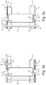
- Fig. 3a shows the attachment of the battery cell 11 at its positive electrical connection contact 33 by means of the connection element 15 and the electrical connection to the negative electrical connection contact 34 via a connection element 15 with the underlying connection structure 14. It can be clearly seen that the connection element 15 between the first Holding structure 12 and the underside of the upper connection structure 14 rests or the lower connection element 15 between the second support structure 13 and the lower connection structure 14 is arranged.
- a first possible attachment variant is shown on the left side of the cell 11.
- a fastening element 25 is provided which is fixed by two screws, which reach through the holding structure 12, 13, and thus fixes the holding structures 12, 13 with the battery cells 11 inserted therein.
- connection structures 14 can be fixed via through openings 49 in the connection structure 14 by means of second fastening elements 26, for example in the form of plastic screws 26, into threaded bores of the first and second support structures 12 and 13, respectively.
- second fastening elements 26 for example in the form of plastic screws 26, into threaded bores of the first and second support structures 12 and 13, respectively.
- plastic threaded bolt and rivets eg. Plastic rivets can be used with a press connection, thus defining the connection structures 14 to the corresponding support structures 12, 13.
- About the first fastener 25 can be a defined distance between the support structures 12, 13 set so that the battery cells 11 between the first and second support structure 12, 13 are securely fixed in the receiving openings 21 of the first and second support structure 12, 13 and are not exposed to mechanical stress ,
- Fig. 3b shows a sectional view through a battery pack with a fastener, which allows fastening of a plurality of battery packs 10 a, 10 b, 10 c together.
- Both the first and the second holding structure 12, 13 each have a passage opening 50, wherein corresponding thereto the connection structure 14 likewise has passage openings 49.
- the through holes 49 and 50 are aligned with each other and thus make it possible to pass a pressing rod 53 through these through holes 49 and 50.
- the pressure bar 53 preferably has an electrically insulating sheath 54, since it is passed through the electrically conductive connection structures 14, without touching them.
- the diameter of the passage opening 49 in the connection structures 14 is greater than the outer diameter of the casing 54, so that a clearance exists between the casing 54 and the connection structures 14, which in addition to avoid electrical contact between connection structures 14 and pressing rod 53 contributes. An electrical contact between Anpressstab 53 and terminal structures 14 is thus even in case of failure of the sheath 54, for example due to damage avoided.
- the diameter of the passage openings 50 in the support structures 12, 13 is less than the diameter of the passage opening 49 in the connection structures 14.
- the diameter of the passage openings 50 in the support structures 12, 13 is matched to the outer diameter of the shell 54 such that the pressure rod 53 can pass without play through the through holes 50. Due to such a dimensioning of the passage openings 50, in addition to the pressure of the pressing device, a centering is created which ensures that a mutual displacement of the connection structures 14 of respective battery packs, even with extremely high mechanical influences, is avoided. A reliable flow of current from one battery pack to the next battery pack is thus given even in extreme conditions, such as may occur in vehicles.
- Fig. 4 shows the structure of a battery pack 10a during assembly. It is shown that individual battery cells 11 are already inserted in the lower or second holding structure 13. Next, the support structure 13 has already been provided with the first fastening elements 25, which has a fastening with the in Fig. 4 allow not shown second support structure 12.
- Fig. 5 shows a connection structure according to the invention 14.
- a bottom 24 a of the connection structure 14 is shown, which, as shown in Fig. 3a or 3b shown, rests on the top of the respective support structure 12 or 13.
- the connection structure 14 has contact openings 16.
- As many contact openings 16 are provided as battery cells 11 are inserted into the respective support structures 12 and 13 respectively.
- In this contact openings 16 project accordingly connecting elements 15, which are preferably secured by friction welding to the underside 24a of the connection structure 14. The attachment of the connection elements 15 takes place before the connection structure 14 with the connection elements 15 is fastened to the electrical connection contacts 33, 34 of the battery cells 11.
- connection structure 14 also has further connections 48, which allow a connection to an operation management system.
- connection structure 14 according to Fig. 5 Through openings 49, which serve for the implementation of Anpressstäben 53 and for receiving first and second fastening elements 25, 26.
- the number of through holes 49 in Fig. 5 not limited to four.
- the various passage openings 49 for the first and second fastening elements 25, 26 or for the pressure bar 53 can have different diameters.
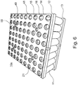
- Fig. 6 is a perspective view of a battery pack 10a according to the invention shown. Similar to in Fig. 1 It can be seen that the connection elements 15 are arranged between the connection structure 14 and the respective support structure 12 and protrude into the respective contact openings 16 or receiving openings 21 of the support structure 12 so as to be connected to the connection contacts 33, 34 of the battery cells 11, not shown here become.
- the battery pack 10a according to FIG Fig. 6 in that the connection structure 14 has passage openings 50 which have a larger diameter than the passage openings 49 of the underlying support structures 12, 13.
- the connections 48 for the BMS can be placed around an edge of the support structure 12, 13.
- FIG. 7 an assembly of a battery block 10 according to the invention is shown, in which representation so far only one battery pack 10 a is mounted.
- An inventive battery block 10 includes a pressure plate 43, the through holes 56 for receiving Anpressstäben 53, which are surrounded by an electrically insulating sheath 54.
- At the end of a Anpressstabes 53 are a screw head 59 and a nut 58 and a disc spring 57 to prevent slippage of the Anpressstabes 53 through the through hole 56.
- an electrically conductive contact plate 41 for example made of copper, is placed on the pressure bars 53 and brought to the pressure plate 43.
- the contact pressure rods 53 also penetrate through holes 55 of the contact plate 41.
- the contact plate 41 projects beyond the pressure plate 43 on at least one side in order to form an electrical connection region 45 of the battery block.
- a first battery pack 10a according to Fig. 6 placed on the pressure bars 53 and moved in the direction of the contact plate 41.
- the Anpressstäbe 53 penetrate the respective casing 54, the through holes 49 of the connection structure 14 and the through holes 50 of the support structure 12 and 13 respectively of the left and right sides of the battery pack 10 a according Fig. 7 ,
- Fig. 8 is another progress in the assembly of the battery pack 10 can be seen.
- There are already two battery packs 10a, 10b invention have been placed on the Anpressstäbe 53, with a third battery pack 10c is already placed on the Anpressstäbe 53 and is just brought to the two already mounted battery packs 10a, 10b.
- the battery packs 10a, 10b, 10c are electrically connected in series, that is to say that the battery cells 11 are arranged in the battery packs 10a, 10b, 10c in such a way that all electrically positive connection contacts 33 are aligned with a connection structure 14 and the electrically negative connection contacts 34 are aligned with the opposite connection structure 14.
- a third battery pack 10c is brought to a second battery pack 10b, the positive pole of the third battery pack 10c being brought to the corresponding negative pole of the second battery pack 10b, so that the connection structures 14 lie against each other over the entire area and thus the best possible and large-area contact between the two Battery packs 10b, 10c allow to use without additional cables or to require additional connection structures.
- This juxtaposition of battery packs according to the invention allows a very space-saving arrangement of battery cells.
- a large-area electrical connection is possible, which has a low heat development during the current flow, whereby an optimal temperature configuration of the battery pack 10 is ensured.
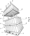
- a fully assembled battery pack 10 composed of five individual battery packs 10a, 10b, 10c, 10d and 10e.
- Each battery pack 10 a, 10 b, 10 c, 10 d and 10 e is bounded on its left or right side by a connection structure 14.
- the battery packs 10a to 10e are defined at the respective outer sides of the first and fifth battery packs 10a, 10e by a contact plate 41 and 42 which is bounded from the outside by a pressure plate 43 and 44, respectively.
- This battery block 10 is, as in the Fig. 7 and 8th represented by four pressure bars 53 with corresponding casing 54 pressed together.
- the Anpressstäbe 53 are provided at their end with a thread that allows the placement of a nut 58 and a clamping of the Anpressstäbe 53, so that a corresponding pressure on the battery packs 10a-10e is exercised and thus a secure electrical connection between the individual Terminal structures 14 is made possible.
- the terminal portions 45 and 46 of the contact plates 41, 42 project respectively beyond the outer dimensions of the battery pack 10a, 10e and the pressure plates 43, 44, or protrude upward.
- Fig. 10 is a sectional view represented by a battery block according to the invention.
- FIGS. 11 and 12 show alternative forms of support structures.
- Fig. 11 For example, a triangular shape of a support structure 13 is shown. How out Fig. 11 is apparent, it is possible to form such an arrangement with only one Anpressstab.
- the connection structures 14 preferably have a corresponding shape, which is slightly smaller in their outer dimensions, so that the connection structures 14 do not protrude beyond the outer edge of the support structure 13 and thus electrical contact of a connection structure 14 with others to prevent electrically conductive materials.
- This holding structure 13 includes 3 receiving openings 21 for receiving battery cells 11 and a through hole 50 for receiving a pressure bar.
- a circular support structure 13 is shown, which represents seven receiving openings 21 into which seven battery cells 11 can be inserted.
- a support structure 13 is held together by three pressure bars, the be passed through the three through holes 50.
- the terminal structures 14 would have a circular structure, which would be smaller in diameter than the diameter of the corresponding support structure thirteenth
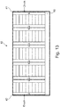
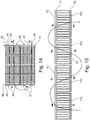
- Fig. 13 an alternative embodiment of a battery pack is shown.
- pressure bars 53 with their sheathing 54
- Fig. 14 a connection of two battery blocks 10 is shown. In each case four battery packs 10a-10d per battery block 10 are connected in series.
- a contact plate 42 makes it possible to place an upper battery block 10 on the lower battery block 10, in which case the negative pole of the lower battery block 10 is connected to the positive pole of the upper battery block via a common contact plate 42.
- On the right side of the upper battery block 10 is the negative terminal of the upper battery block 10.
- FIG Fig. 15 An alternative arrangement of battery packs 10a-10d is in FIG Fig. 15 shown.
- battery packs according to the invention 10a to 10d are arranged side by side, so that the connection structures 14 of adjacent battery packs 10a, 10b can be connected to a common contact plate 42 and thus to achieve the greatest possible contact area and to ensure optimum flow of current.
- a battery block which has a plurality of battery packs, wherein the electrically positive and electrically negative terminal contacts of the battery cells of a battery pack are disposed on opposite sides of the battery pack and on each of the two sides an electrically conductive connection structure is present, with the respective electrical connection contacts the battery cells of a battery pack is connected, wherein two adjacent battery packs are each arranged so that the electrical connection contacts of the cells of adjacent battery packs, which are aligned to one side, are electrically oppositely poled, wherein on one side of the battery pack, a common contact plate on the Terminal structures of the adjacent battery packs extends and the electrically oppositely poled terminal structures connected in series with each other.
- a battery pack in which the individual battery packs are arranged next to each other that is, in which the longitudinal axes of the battery cells 11 of adjacent battery packs 10a, 10b are parallel to each other, holding structures 12, 13, pressure plates 43, 44, pressing devices 53, etc.
- a particular advantage of the embodiment described above is that an optimal current flow is achieved by the large-area connection structures and contact plates, which is not affected by additional electrical connections or cross-sectional tapers.
Claims (13)
- Bloc-batterie (10) incluant :- au moins deux paquets de batteries (10a, 10b, 10c, 10d, 10e),- dans lequel chaque paquet de batteries inclut au moins deux cellules de batterie (11), qui sont réalisées chacune sous forme de cellules rondes,- dans lequel tous les contacts de connexion électrique positifs (33) des cellules de batterie (11) du paquet de batteries sont situés sur un premier côté et tous les contacts de connexion électrique négatifs (34) des cellules de batterie (11) sont agencés sur le côté opposé du paquet de batteries,- dans lequel une structure de connexion (14) est associée à chaque côté de connexion électrique d'un paquet de batteries,- dans lequel les structures de connexion (14) de polarité électrique opposée de deux paquets de batteries voisins (10a, 10b) sont appliquées l'une contre l'autre sur toute la surface, afin d'atteindre une liaison à grande surface entre les paquets de batteries (10a, 10b),caractérisé en ce que
les contacts de connexion électrique positifs (33) des cellules de batterie (11) sont reliés électriquement respectivement à un élément de connexion (15) sur une première structure de connexion (14) du paquet de batteries, et les contacts de connexion électrique négatifs (34) des cellules de batterie (11) sont reliés électriquement respectivement à un élément de connexion (15) sur une seconde structure de connexion (14),
dans lequel les éléments de connexion (15) sont fixés respectivement sur un côté des structures de connexion (14) qui est tourné vers les cellules de batterie (11),
dans lequel les éléments de connexion (15) sont réalisés en forme de ruban et sont fixés sur les contacts de connexion des cellules de batterie, et les éléments de connexion (15) sont fixés sur la structure de connexion (14) au moyen d'un processus d'assemblage. - Bloc-batterie selon la revendication 1, dans lequel les paquets de batteries (10a, 10b, 10c, 10d, 10e) sont branchés en série et des contacts de connexion électriquement opposés des cellules de batterie (11) sont agencés sur les côtés extérieurs opposés du bloc de batterie (10).
- Bloc-batterie selon la revendication 1 ou 2, dans lequel les paquets de batteries (10a, 10b, 10c, 10d, 10e) du bloc-batterie sont pressés les uns contre les autres en exerçant une pression sur les paquets de batteries (10a, 10b, 10c, 10d, 10e) extérieurs, et il est prévu au moins un dispositif de pressage destiné à presser les paquets de batteries (10a, 10b, 10c, 10d, 10e) les uns contre les autres.
- Bloc-batterie selon la revendication 3, dans lequel ledit au moins un dispositif de pressage est réalisé sous forme de barreau de pressage (53), et des moyens de fixation (57, 58, 59) destinés à la fixation sont agencés sur ledit au moins un barreau de pressage (53), au moyen desquels lesdits au moins deux paquets de batteries peuvent être pressés l'un contre l'autre.
- Bloc-batterie selon la revendication 4, dans lequel les structures de connexion (14) du paquet de batteries comprennent respectivement au moins une ouverture traversante (49) pour la réception dudit au moins un barreau de pressage (53).
- Bloc-batterie selon l'une des revendications précédentes, dans lequel une plaque de contact (41, 42) respective est associée à chacune des deux structures de connexion extérieures (14) des paquets de batteries appliqués l'un contre l'autre, lesdites plaques de contact comportent chacune une zone de connexion (45, 46) pour la connexion du bloc-batterie à un appareil de charge ou à un dispositif de consommation électrique.
- Bloc-batterie selon l'une des revendications précédentes, dans lequel une plaque de pression électriquement isolante (43, 44) est agencée respectivement sur les deux côtés extérieurs du paquet de batteries.
- Bloc-batterie selon l'une des revendications précédentes, dans lequel une première structure de maintien (12) est agencée sur le côté des contacts de connexion électrique positifs (33) des cellules de batterie (11) et une seconde structure de maintien (13) est agencée sur le côté des contacts de connexion électrique négatifs (34) des cellules de batterie (11) pour la réception desdites au moins deux cellules de batterie (11), ladite structure de maintien (12, 13) présentant une surface (24) sur laquelle s'applique la structure de connexion (14), et la structure de maintien (12, 13) présente des ouvertures de connexion (21) et au moins une ouverture traversante (50).
- Bloc-batterie selon la revendication 8, dans lequel l'ouverture traversante (50) dans la structure de maintien (12, 13) a un diamètre plus petit que l'ouverture traversante (49) des structures de connexion (14).
- Bloc-batterie selon l'une des revendications précédentes, dans lequel la structure de connexion (14) a une surface qui correspond au moins à la somme des sections transversales des cellules de batterie (11) contenues dans le paquet de batteries.
- Bloc-batterie selon l'une des revendications précédentes, dans lequel la longueur d'une structure de connexion (14), dans une direction longitudinale, est plus grande que la somme des diamètres individuels des cellules de batterie dans cette direction longitudinale.
- Bloc-batterie selon l'une des revendications précédentes, dans lequel la largeur d'une structure de connexion (14), dans une direction en largeur, est plus grande que la somme des largeurs individuelles ou des diamètres individuels des cellules de batterie (11) dans cette direction en largeur.
- Procédé pour la réalisation d'un bloc-batterie, incluant les étapes consistant à :- fournir au moins deux paquets de batteries (10a, 10b, 10c, 10d, 10e), dans lesquels chaque paquet de batteries inclut au moins deux cellules de batterie (11), lesquelles sont réalisées respectivement comme des cellules rondes, et tous les contacts de connexion électrique positifs (33) des cellules de batterie (11) du paquet de batteries sont situés sur un premier côté et tous les contacts de connexion électrique négatifs (34) des cellules de batterie (11) sont agencés sur le côté opposé du paquet de batteries, et une structure de connexion (14) est associée à chaque côté de connexion électrique d'un paquet de batteries, dans lequel les contacts de connexion électrique positifs (33) des cellules de batterie (11) sont reliés électriquement à un élément de connexion respectif (15) sur une première structure de connexion (14) du paquet de batteries, et les contacts de connexion électrique négatifs (34) des cellules de batterie (11) sont reliés électriquement à un élément de connexion respectif (15) au niveau d'une seconde structure de connexion (14), dans lequel les éléments de connexion (15) sont fixés respectivement sur un côté des structures de connexion (14) qui est tourné vers les cellules de batterie (11), et les éléments de connexion (15) sont réalisés sous forme de ruban et sont fixés sur les contacts de connexion des cellules de batterie, et les éléments de connexion (15) sont fixés sur la structure de connexion (14) au moyen d'une procédure d'assemblage ; et- presser les uns contre les autres des paquets de batteries voisins (10a, 10b), de telle sorte que les structures de connexion (14) de polarité électrique opposée des deux paquets de batteries voisins (10a, 10b) sont appliquées l'une contre l'autre sur une grande surface, afin d'obtenir une liaison à grande surface entre les paquets de batteries (10a, 10b).
Applications Claiming Priority (2)
| Application Number | Priority Date | Filing Date | Title |
|---|---|---|---|
| DE102015104741.1A DE102015104741A1 (de) | 2015-03-27 | 2015-03-27 | Batterieblock, und Verfahren zur Herstellung eines Batterieblocks |
| PCT/EP2015/069421 WO2016155846A1 (fr) | 2015-03-27 | 2015-08-25 | Bloc-batterie, et procédé de fabrication d'un bloc-batterie |
Publications (2)
| Publication Number | Publication Date |
|---|---|
| EP3275028A1 EP3275028A1 (fr) | 2018-01-31 |
| EP3275028B1 true EP3275028B1 (fr) | 2019-10-09 |
Family
ID=54065331
Family Applications (1)
| Application Number | Title | Priority Date | Filing Date |
|---|---|---|---|
| EP15760116.2A Active EP3275028B1 (fr) | 2015-03-27 | 2015-08-25 | Bloc-batterie, et procédé de fabrication d'un bloc-batterie |
Country Status (7)
| Country | Link |
|---|---|
| US (1) | US10586959B2 (fr) |
| EP (1) | EP3275028B1 (fr) |
| JP (1) | JP6653749B2 (fr) |
| KR (1) | KR102349223B1 (fr) |
| CN (1) | CN107646149A (fr) |
| DE (1) | DE102015104741A1 (fr) |
| WO (1) | WO2016155846A1 (fr) |
Families Citing this family (21)
| Publication number | Priority date | Publication date | Assignee | Title |
|---|---|---|---|---|
| EP3241254B1 (fr) * | 2015-04-16 | 2018-04-25 | Neuss, Wilhem | Module de batterie |
| US20170162839A1 (en) * | 2015-12-08 | 2017-06-08 | Bosch Battery Systems, Llc | Super Cells Formed of Cylindrical Electrochemical Cells |
| CN106876644A (zh) * | 2017-03-30 | 2017-06-20 | 深圳市沃特玛电池有限公司 | 一种电连接板 |
| KR102223809B1 (ko) * | 2017-11-09 | 2021-03-04 | 주식회사 엘지화학 | 2차 전지 셀 모듈 및 그 조립 방법 |
| AU2018382225A1 (en) * | 2017-12-15 | 2020-07-30 | Kevin Stephen Davies | Battery pack |
| KR102329342B1 (ko) * | 2018-01-24 | 2021-11-18 | 주식회사 엘지에너지솔루션 | 배터리 모듈, 이러한 배터리 모듈을 포함하는 배터리 팩 및 이러한 배터리 팩을 포함하는 자동차 |
| DE102018109889A1 (de) * | 2018-04-24 | 2019-10-24 | Webasto SE | Antriebsbatterie für ein Kraftfahrzeug |
| DE102018207153A1 (de) * | 2018-05-08 | 2019-11-14 | Bayerische Motoren Werke Aktiengesellschaft | Integriertes Kontaktierungs- und Abstandshalteelement für ein Batteriemodul einer Hochvoltbatterie eines Kraftfahrzeugs, Batteriemodul, Verfahren zum Herstellen eines Batteriemoduls sowie Hochvoltbatterie |
| EP3573127A1 (fr) * | 2018-05-25 | 2019-11-27 | E-Seven Systems Technology Management Ltd | Dispositif pour cellules destinée à stocker de l'énergie électrique doté de l'élément de contact à ressort |
| AT521526B1 (de) * | 2018-08-07 | 2021-09-15 | Voltlabor Gmbh | Batterie |
| US20200052259A1 (en) * | 2018-08-09 | 2020-02-13 | Tiveni MergeCo Inc. | Battery module with bottom plate on which positioning elements are arranged to position battery cells |
| KR102317265B1 (ko) * | 2018-11-02 | 2021-10-22 | 주식회사 엘지에너지솔루션 | 로봇 아암을 포함하는 로봇 |
| CN110137403B (zh) * | 2019-05-05 | 2024-04-16 | 中国科学院电工研究所 | 一种紧凑型集装箱储能系统集成结构 |
| DE102019113914A1 (de) * | 2019-05-24 | 2020-11-26 | Bayerische Motoren Werke Aktiengesellschaft | Deckelbaugruppe für ein Zellgehäuse einer prismatischen Batteriezelle mit Anschlusskontakten für eine Heizeinrichtung, Batteriezelle sowie Hochvoltbatterie |
| FR3099300B1 (fr) * | 2019-07-22 | 2021-12-31 | Tyva Energie | Batterie électrique et procédé de montage d’une telle batterie |
| EP4128429A1 (fr) * | 2020-04-01 | 2023-02-08 | TVS Motor Company Limited | Bloc-batterie |
| KR102477215B1 (ko) * | 2020-10-27 | 2022-12-13 | 조수희 | 배터리 팩 모듈 |
| EP4280351A4 (fr) * | 2021-12-15 | 2024-04-17 | Contemporary Amperex Technology Co Ltd | Batterie, dispositif électrique et procédé de fabrication de batterie |
| CN114374061B (zh) * | 2021-12-31 | 2023-10-31 | 广东电将军能源有限公司 | 一种具有绝缘防护装置的储能电源 |
| CN115189431A (zh) * | 2022-06-08 | 2022-10-14 | 云南电网有限责任公司楚雄供电局 | 一种变电站直流电池组装置及其自动保容系统 |
| CN115055849B (zh) * | 2022-07-27 | 2022-11-08 | 宜宾长盈精密技术有限公司 | 一种电池盖板极柱焊接工装 |
Family Cites Families (12)
| Publication number | Priority date | Publication date | Assignee | Title |
|---|---|---|---|---|
| US7671565B2 (en) * | 2006-02-13 | 2010-03-02 | Tesla Motors, Inc. | Battery pack and method for protecting batteries |
| JP5179580B2 (ja) * | 2007-07-16 | 2013-04-10 | エルジー・ケム・リミテッド | 機械的接続様式による二次バッテリーパック |
| JP2010282811A (ja) * | 2009-06-04 | 2010-12-16 | Sanyo Electric Co Ltd | パック電池 |
| EP2438640B1 (fr) * | 2009-06-05 | 2015-12-16 | K2 Energy Solutions, Inc. | Bloc de batteries au lithium-ion à refroidissement passif |
| DE102010013022A1 (de) | 2010-03-26 | 2011-09-29 | Daimler Ag | Fahrzeug mit einer Unterbodenverkleidung |
| DE102010013002A1 (de) * | 2010-03-26 | 2011-09-29 | Daimler Ag | Batterie mit einem Zellenstapel |
| US8679667B2 (en) | 2010-10-29 | 2014-03-25 | GM Global Technology Operations LLC | One piece compression resistant prismatic cell |
| US20130224532A1 (en) | 2010-11-05 | 2013-08-29 | Alelion Batteries Ab | Battery assembly |
| CN202423430U (zh) * | 2011-12-22 | 2012-09-05 | 深圳市沃特玛电池有限公司 | 一种电池组的软性电路连接结构 |
| AU2012373356B2 (en) * | 2012-03-12 | 2016-02-25 | Chung Peng Liew | Non-welded battery module |
| DE102013100545B4 (de) * | 2013-01-18 | 2022-12-01 | Cayago Tec Gmbh | Wasserfahrzeug mit einer Akkumulatoreinheit |
| US10651437B2 (en) | 2014-05-08 | 2020-05-12 | H-Tech Ag | Battery pack and method for assembling a battery pack |
-
2015
- 2015-03-27 DE DE102015104741.1A patent/DE102015104741A1/de not_active Withdrawn
- 2015-08-25 JP JP2018500849A patent/JP6653749B2/ja active Active
- 2015-08-25 US US15/561,320 patent/US10586959B2/en active Active
- 2015-08-25 KR KR1020177030918A patent/KR102349223B1/ko active IP Right Grant
- 2015-08-25 WO PCT/EP2015/069421 patent/WO2016155846A1/fr active Application Filing
- 2015-08-25 EP EP15760116.2A patent/EP3275028B1/fr active Active
- 2015-08-25 CN CN201580080309.9A patent/CN107646149A/zh active Pending
Non-Patent Citations (1)
| Title |
|---|
| None * |
Also Published As
| Publication number | Publication date |
|---|---|
| KR102349223B1 (ko) | 2022-01-10 |
| JP6653749B2 (ja) | 2020-02-26 |
| WO2016155846A1 (fr) | 2016-10-06 |
| CN107646149A (zh) | 2018-01-30 |
| US10586959B2 (en) | 2020-03-10 |
| DE102015104741A1 (de) | 2016-09-29 |
| JP2018512720A (ja) | 2018-05-17 |
| US20180102519A1 (en) | 2018-04-12 |
| EP3275028A1 (fr) | 2018-01-31 |
| KR20180011071A (ko) | 2018-01-31 |
Similar Documents
| Publication | Publication Date | Title |
|---|---|---|
| EP3275028B1 (fr) | Bloc-batterie, et procédé de fabrication d'un bloc-batterie | |
| EP3140874B1 (fr) | Batterie et procédé de montage d'un bloc de batteries | |
| EP2789029B1 (fr) | Batterie et bloc d'éléments d'une batterie | |
| WO2010037797A2 (fr) | Unité d'accumulation d'énergie | |
| EP2593982B1 (fr) | Module d'éléments de batterie, batterie et véhicule à moteur | |
| WO2010076055A1 (fr) | Module de batterie à couche isolante | |
| WO2010115559A1 (fr) | Cellule galvanique, empilement de cellules et dissipateur thermique | |
| WO2017102161A1 (fr) | Boîtier de logement d'un empilement de piles à combustible, de cellules ou de condensateurs | |
| WO2011054586A1 (fr) | Procédé pour relier un pôle de batterie au niveau d'un premier élément de batterie à un pôle de batterie au niveau d'un second élément de batterie, batterie constituée d'éléments de batterie reliés entre eux et système de batteries | |
| DE102016219459A1 (de) | Aufsteck-clip | |
| DE102013015749A1 (de) | Zellblock für eine Batterie | |
| DE112016004706T5 (de) | Vorrichtung umfassend batteriezellen und ein verfahren zum zusammenbauen | |
| WO2012062396A1 (fr) | Batterie comportant un ensemble de cellules | |
| EP2735039B1 (fr) | Système de mise en contact électrique des éléments d'un accumulateur d'énergie | |
| DE102009035461A1 (de) | Batterie mit einer Vielzahl von Batterieeinzelzellen | |
| DE102012219057A1 (de) | Energiespeichermodul und Verfahren zur Herstellung des Energiespeichermoduls | |
| DE102016205920A1 (de) | Batteriepack | |
| DE102016205124B3 (de) | Batteriepack | |
| EP3465797B1 (fr) | Batterie avec des sections de batterie et des éléments de contact à ces sections | |
| WO2013000617A1 (fr) | Élément de contact destiné à la mise en contact mécanique, thermique et électrique d'un accumulateur d'énergie | |
| DE102012219778A1 (de) | Batteriemodulanschluss bildende Stromschiene | |
| DE102014106414A1 (de) | Batteriepack und Verfahren zur Montage des Batteriepacks | |
| DE102012018088A1 (de) | Vorrichtung zum elektrischen Kontaktieren von prismatischen Batterieeinzelzellen | |
| EP3117472B1 (fr) | Arrengement de connecteur de liaison électrique avec les bornes de sortie d'une cellule électrochimique | |
| EP2347466B1 (fr) | Unité d'accumulation d'énergie |
Legal Events
| Date | Code | Title | Description |
|---|---|---|---|
| STAA | Information on the status of an ep patent application or granted ep patent |
Free format text: STATUS: THE INTERNATIONAL PUBLICATION HAS BEEN MADE |
|
| PUAI | Public reference made under article 153(3) epc to a published international application that has entered the european phase |
Free format text: ORIGINAL CODE: 0009012 |
|
| STAA | Information on the status of an ep patent application or granted ep patent |
Free format text: STATUS: REQUEST FOR EXAMINATION WAS MADE |
|
| 17P | Request for examination filed |
Effective date: 20171011 |
|
| AK | Designated contracting states |
Kind code of ref document: A1 Designated state(s): AL AT BE BG CH CY CZ DE DK EE ES FI FR GB GR HR HU IE IS IT LI LT LU LV MC MK MT NL NO PL PT RO RS SE SI SK SM TR |
|
| AX | Request for extension of the european patent |
Extension state: BA ME |
|
| DAV | Request for validation of the european patent (deleted) | ||
| DAX | Request for extension of the european patent (deleted) | ||
| STAA | Information on the status of an ep patent application or granted ep patent |
Free format text: STATUS: EXAMINATION IS IN PROGRESS |
|
| 17Q | First examination report despatched |
Effective date: 20190131 |
|
| GRAP | Despatch of communication of intention to grant a patent |
Free format text: ORIGINAL CODE: EPIDOSNIGR1 |
|
| STAA | Information on the status of an ep patent application or granted ep patent |
Free format text: STATUS: GRANT OF PATENT IS INTENDED |
|
| INTG | Intention to grant announced |
Effective date: 20190506 |
|
| GRAS | Grant fee paid |
Free format text: ORIGINAL CODE: EPIDOSNIGR3 |
|
| GRAA | (expected) grant |
Free format text: ORIGINAL CODE: 0009210 |
|
| STAA | Information on the status of an ep patent application or granted ep patent |
Free format text: STATUS: THE PATENT HAS BEEN GRANTED |
|
| AK | Designated contracting states |
Kind code of ref document: B1 Designated state(s): AL AT BE BG CH CY CZ DE DK EE ES FI FR GB GR HR HU IE IS IT LI LT LU LV MC MK MT NL NO PL PT RO RS SE SI SK SM TR |
|
| REG | Reference to a national code |
Ref country code: GB Ref legal event code: FG4D Free format text: NOT ENGLISH |
|
| REG | Reference to a national code |
Ref country code: CH Ref legal event code: EP |
|
| REG | Reference to a national code |
Ref country code: DE Ref legal event code: R096 Ref document number: 502015010618 Country of ref document: DE |
|
| REG | Reference to a national code |
Ref country code: IE Ref legal event code: FG4D Free format text: LANGUAGE OF EP DOCUMENT: GERMAN |
|
| REG | Reference to a national code |
Ref country code: AT Ref legal event code: REF Ref document number: 1189854 Country of ref document: AT Kind code of ref document: T Effective date: 20191115 Ref country code: CH Ref legal event code: NV Representative=s name: FELBER UND PARTNER AG, CH |
|
| REG | Reference to a national code |
Ref country code: SE Ref legal event code: TRGR |
|
| REG | Reference to a national code |
Ref country code: NL Ref legal event code: FP |
|
| REG | Reference to a national code |
Ref country code: NO Ref legal event code: T2 Effective date: 20191009 |
|
| REG | Reference to a national code |
Ref country code: LT Ref legal event code: MG4D |
|
| PG25 | Lapsed in a contracting state [announced via postgrant information from national office to epo] |
Ref country code: PT Free format text: LAPSE BECAUSE OF FAILURE TO SUBMIT A TRANSLATION OF THE DESCRIPTION OR TO PAY THE FEE WITHIN THE PRESCRIBED TIME-LIMIT Effective date: 20200210 Ref country code: ES Free format text: LAPSE BECAUSE OF FAILURE TO SUBMIT A TRANSLATION OF THE DESCRIPTION OR TO PAY THE FEE WITHIN THE PRESCRIBED TIME-LIMIT Effective date: 20191009 Ref country code: GR Free format text: LAPSE BECAUSE OF FAILURE TO SUBMIT A TRANSLATION OF THE DESCRIPTION OR TO PAY THE FEE WITHIN THE PRESCRIBED TIME-LIMIT Effective date: 20200110 Ref country code: LV Free format text: LAPSE BECAUSE OF FAILURE TO SUBMIT A TRANSLATION OF THE DESCRIPTION OR TO PAY THE FEE WITHIN THE PRESCRIBED TIME-LIMIT Effective date: 20191009 Ref country code: BG Free format text: LAPSE BECAUSE OF FAILURE TO SUBMIT A TRANSLATION OF THE DESCRIPTION OR TO PAY THE FEE WITHIN THE PRESCRIBED TIME-LIMIT Effective date: 20200109 Ref country code: PL Free format text: LAPSE BECAUSE OF FAILURE TO SUBMIT A TRANSLATION OF THE DESCRIPTION OR TO PAY THE FEE WITHIN THE PRESCRIBED TIME-LIMIT Effective date: 20191009 Ref country code: LT Free format text: LAPSE BECAUSE OF FAILURE TO SUBMIT A TRANSLATION OF THE DESCRIPTION OR TO PAY THE FEE WITHIN THE PRESCRIBED TIME-LIMIT Effective date: 20191009 |
|
| PG25 | Lapsed in a contracting state [announced via postgrant information from national office to epo] |
Ref country code: RS Free format text: LAPSE BECAUSE OF FAILURE TO SUBMIT A TRANSLATION OF THE DESCRIPTION OR TO PAY THE FEE WITHIN THE PRESCRIBED TIME-LIMIT Effective date: 20191009 Ref country code: IS Free format text: LAPSE BECAUSE OF FAILURE TO SUBMIT A TRANSLATION OF THE DESCRIPTION OR TO PAY THE FEE WITHIN THE PRESCRIBED TIME-LIMIT Effective date: 20200224 Ref country code: HR Free format text: LAPSE BECAUSE OF FAILURE TO SUBMIT A TRANSLATION OF THE DESCRIPTION OR TO PAY THE FEE WITHIN THE PRESCRIBED TIME-LIMIT Effective date: 20191009 |
|
| PG25 | Lapsed in a contracting state [announced via postgrant information from national office to epo] |
Ref country code: AL Free format text: LAPSE BECAUSE OF FAILURE TO SUBMIT A TRANSLATION OF THE DESCRIPTION OR TO PAY THE FEE WITHIN THE PRESCRIBED TIME-LIMIT Effective date: 20191009 |
|
| REG | Reference to a national code |
Ref country code: DE Ref legal event code: R097 Ref document number: 502015010618 Country of ref document: DE |
|
| PG2D | Information on lapse in contracting state deleted |
Ref country code: IS |
|
| PG25 | Lapsed in a contracting state [announced via postgrant information from national office to epo] |
Ref country code: IS Free format text: LAPSE BECAUSE OF FAILURE TO SUBMIT A TRANSLATION OF THE DESCRIPTION OR TO PAY THE FEE WITHIN THE PRESCRIBED TIME-LIMIT Effective date: 20200209 Ref country code: EE Free format text: LAPSE BECAUSE OF FAILURE TO SUBMIT A TRANSLATION OF THE DESCRIPTION OR TO PAY THE FEE WITHIN THE PRESCRIBED TIME-LIMIT Effective date: 20191009 Ref country code: DK Free format text: LAPSE BECAUSE OF FAILURE TO SUBMIT A TRANSLATION OF THE DESCRIPTION OR TO PAY THE FEE WITHIN THE PRESCRIBED TIME-LIMIT Effective date: 20191009 Ref country code: RO Free format text: LAPSE BECAUSE OF FAILURE TO SUBMIT A TRANSLATION OF THE DESCRIPTION OR TO PAY THE FEE WITHIN THE PRESCRIBED TIME-LIMIT Effective date: 20191009 Ref country code: CZ Free format text: LAPSE BECAUSE OF FAILURE TO SUBMIT A TRANSLATION OF THE DESCRIPTION OR TO PAY THE FEE WITHIN THE PRESCRIBED TIME-LIMIT Effective date: 20191009 |
|
| PLBE | No opposition filed within time limit |
Free format text: ORIGINAL CODE: 0009261 |
|
| STAA | Information on the status of an ep patent application or granted ep patent |
Free format text: STATUS: NO OPPOSITION FILED WITHIN TIME LIMIT |
|
| PG25 | Lapsed in a contracting state [announced via postgrant information from national office to epo] |
Ref country code: SK Free format text: LAPSE BECAUSE OF FAILURE TO SUBMIT A TRANSLATION OF THE DESCRIPTION OR TO PAY THE FEE WITHIN THE PRESCRIBED TIME-LIMIT Effective date: 20191009 Ref country code: SM Free format text: LAPSE BECAUSE OF FAILURE TO SUBMIT A TRANSLATION OF THE DESCRIPTION OR TO PAY THE FEE WITHIN THE PRESCRIBED TIME-LIMIT Effective date: 20191009 |
|
| 26N | No opposition filed |
Effective date: 20200710 |
|
| REG | Reference to a national code |
Ref country code: DE Ref legal event code: R079 Ref document number: 502015010618 Country of ref document: DE Free format text: PREVIOUS MAIN CLASS: H01M0002100000 Ipc: H01M0050200000 |
|
| PG25 | Lapsed in a contracting state [announced via postgrant information from national office to epo] |
Ref country code: SI Free format text: LAPSE BECAUSE OF FAILURE TO SUBMIT A TRANSLATION OF THE DESCRIPTION OR TO PAY THE FEE WITHIN THE PRESCRIBED TIME-LIMIT Effective date: 20191009 |
|
| PG25 | Lapsed in a contracting state [announced via postgrant information from national office to epo] |
Ref country code: MC Free format text: LAPSE BECAUSE OF FAILURE TO SUBMIT A TRANSLATION OF THE DESCRIPTION OR TO PAY THE FEE WITHIN THE PRESCRIBED TIME-LIMIT Effective date: 20191009 |
|
| PG25 | Lapsed in a contracting state [announced via postgrant information from national office to epo] |
Ref country code: LU Free format text: LAPSE BECAUSE OF NON-PAYMENT OF DUE FEES Effective date: 20200825 |
|
| REG | Reference to a national code |
Ref country code: BE Ref legal event code: MM Effective date: 20200831 |
|
| PG25 | Lapsed in a contracting state [announced via postgrant information from national office to epo] |
Ref country code: IE Free format text: LAPSE BECAUSE OF NON-PAYMENT OF DUE FEES Effective date: 20200825 Ref country code: BE Free format text: LAPSE BECAUSE OF NON-PAYMENT OF DUE FEES Effective date: 20200831 |
|
| PG25 | Lapsed in a contracting state [announced via postgrant information from national office to epo] |
Ref country code: TR Free format text: LAPSE BECAUSE OF FAILURE TO SUBMIT A TRANSLATION OF THE DESCRIPTION OR TO PAY THE FEE WITHIN THE PRESCRIBED TIME-LIMIT Effective date: 20191009 Ref country code: MT Free format text: LAPSE BECAUSE OF FAILURE TO SUBMIT A TRANSLATION OF THE DESCRIPTION OR TO PAY THE FEE WITHIN THE PRESCRIBED TIME-LIMIT Effective date: 20191009 Ref country code: CY Free format text: LAPSE BECAUSE OF FAILURE TO SUBMIT A TRANSLATION OF THE DESCRIPTION OR TO PAY THE FEE WITHIN THE PRESCRIBED TIME-LIMIT Effective date: 20191009 |
|
| PG25 | Lapsed in a contracting state [announced via postgrant information from national office to epo] |
Ref country code: MK Free format text: LAPSE BECAUSE OF FAILURE TO SUBMIT A TRANSLATION OF THE DESCRIPTION OR TO PAY THE FEE WITHIN THE PRESCRIBED TIME-LIMIT Effective date: 20191009 |
|
| PGFP | Annual fee paid to national office [announced via postgrant information from national office to epo] |
Ref country code: NL Payment date: 20230823 Year of fee payment: 9 |
|
| PGFP | Annual fee paid to national office [announced via postgrant information from national office to epo] |
Ref country code: NO Payment date: 20230822 Year of fee payment: 9 Ref country code: IT Payment date: 20230831 Year of fee payment: 9 Ref country code: GB Payment date: 20230824 Year of fee payment: 9 Ref country code: FI Payment date: 20230823 Year of fee payment: 9 Ref country code: CH Payment date: 20230902 Year of fee payment: 9 Ref country code: AT Payment date: 20230818 Year of fee payment: 9 |
|
| PGFP | Annual fee paid to national office [announced via postgrant information from national office to epo] |
Ref country code: SE Payment date: 20230823 Year of fee payment: 9 Ref country code: FR Payment date: 20230821 Year of fee payment: 9 Ref country code: DE Payment date: 20230830 Year of fee payment: 9 |
|
| REG | Reference to a national code |
Ref country code: DE Ref legal event code: R082 Ref document number: 502015010618 Country of ref document: DE Representative=s name: TER MEER STEINMEISTER & PARTNER PATENTANWAELTE, DE |