EP3274071B1 - Protecting an optical particle sensor from particulate deposits by thermophoresis - Google Patents
Protecting an optical particle sensor from particulate deposits by thermophoresis Download PDFInfo
- Publication number
- EP3274071B1 EP3274071B1 EP16713753.8A EP16713753A EP3274071B1 EP 3274071 B1 EP3274071 B1 EP 3274071B1 EP 16713753 A EP16713753 A EP 16713753A EP 3274071 B1 EP3274071 B1 EP 3274071B1
- Authority
- EP
- European Patent Office
- Prior art keywords
- region
- sensor
- particle
- channel
- flow channel
- Prior art date
- Legal status (The legal status is an assumption and is not a legal conclusion. Google has not performed a legal analysis and makes no representation as to the accuracy of the status listed.)
- Active
Links
- 239000002245 particle Substances 0.000 title claims description 144
- 230000003287 optical effect Effects 0.000 title claims description 19
- 238000001089 thermophoresis Methods 0.000 title description 12
- 238000010438 heat treatment Methods 0.000 claims description 68
- 238000001816 cooling Methods 0.000 claims description 17
- 238000000034 method Methods 0.000 claims description 17
- 230000008878 coupling Effects 0.000 claims description 5
- 238000010168 coupling process Methods 0.000 claims description 5
- 238000005859 coupling reaction Methods 0.000 claims description 5
- 230000001939 inductive effect Effects 0.000 claims description 4
- 239000012855 volatile organic compound Substances 0.000 claims description 4
- 230000003213 activating effect Effects 0.000 claims 1
- 230000000694 effects Effects 0.000 description 9
- 239000000463 material Substances 0.000 description 8
- 238000009792 diffusion process Methods 0.000 description 7
- 230000001965 increasing effect Effects 0.000 description 7
- 150000001875 compounds Chemical class 0.000 description 6
- 230000001419 dependent effect Effects 0.000 description 5
- 238000001914 filtration Methods 0.000 description 5
- 238000005259 measurement Methods 0.000 description 5
- 239000013618 particulate matter Substances 0.000 description 5
- 238000011045 prefiltration Methods 0.000 description 5
- 238000013459 approach Methods 0.000 description 4
- WSFSSNUMVMOOMR-UHFFFAOYSA-N Formaldehyde Chemical compound O=C WSFSSNUMVMOOMR-UHFFFAOYSA-N 0.000 description 3
- 230000001276 controlling effect Effects 0.000 description 3
- 230000008021 deposition Effects 0.000 description 3
- 238000001514 detection method Methods 0.000 description 3
- 230000005484 gravity Effects 0.000 description 3
- 230000008901 benefit Effects 0.000 description 2
- 230000008859 change Effects 0.000 description 2
- 238000011109 contamination Methods 0.000 description 2
- 230000003247 decreasing effect Effects 0.000 description 2
- 238000013461 design Methods 0.000 description 2
- 239000007788 liquid Substances 0.000 description 2
- 238000004806 packaging method and process Methods 0.000 description 2
- 239000004065 semiconductor Substances 0.000 description 2
- 239000007787 solid Substances 0.000 description 2
- 239000012780 transparent material Substances 0.000 description 2
- OKTJSMMVPCPJKN-UHFFFAOYSA-N Carbon Chemical compound [C] OKTJSMMVPCPJKN-UHFFFAOYSA-N 0.000 description 1
- 229920001609 Poly(3,4-ethylenedioxythiophene) Polymers 0.000 description 1
- 238000009825 accumulation Methods 0.000 description 1
- 239000000443 aerosol Substances 0.000 description 1
- 150000001298 alcohols Chemical class 0.000 description 1
- 239000000919 ceramic Substances 0.000 description 1
- 239000004927 clay Substances 0.000 description 1
- 239000012141 concentrate Substances 0.000 description 1
- 238000012937 correction Methods 0.000 description 1
- 239000013078 crystal Substances 0.000 description 1
- 239000003599 detergent Substances 0.000 description 1
- 230000003467 diminishing effect Effects 0.000 description 1
- 238000009826 distribution Methods 0.000 description 1
- 238000001900 extreme ultraviolet lithography Methods 0.000 description 1
- 239000012530 fluid Substances 0.000 description 1
- 239000002223 garnet Substances 0.000 description 1
- 238000004817 gas chromatography Methods 0.000 description 1
- 229910021389 graphene Inorganic materials 0.000 description 1
- 230000036541 health Effects 0.000 description 1
- 229910010272 inorganic material Inorganic materials 0.000 description 1
- 239000011147 inorganic material Substances 0.000 description 1
- 229910052500 inorganic mineral Inorganic materials 0.000 description 1
- 239000011810 insulating material Substances 0.000 description 1
- 238000009413 insulation Methods 0.000 description 1
- 230000002452 interceptive effect Effects 0.000 description 1
- 238000001459 lithography Methods 0.000 description 1
- 238000004519 manufacturing process Methods 0.000 description 1
- 238000000691 measurement method Methods 0.000 description 1
- 230000007246 mechanism Effects 0.000 description 1
- 239000002184 metal Substances 0.000 description 1
- 239000011707 mineral Substances 0.000 description 1
- 230000008520 organization Effects 0.000 description 1
- 238000001556 precipitation Methods 0.000 description 1
- 230000008569 process Effects 0.000 description 1
- 238000012545 processing Methods 0.000 description 1
- 230000001902 propagating effect Effects 0.000 description 1
- 238000003380 quartz crystal microbalance Methods 0.000 description 1
- 230000001105 regulatory effect Effects 0.000 description 1
- 230000004044 response Effects 0.000 description 1
- 238000005070 sampling Methods 0.000 description 1
- 229910052594 sapphire Inorganic materials 0.000 description 1
- 239000010980 sapphire Substances 0.000 description 1
- 238000000926 separation method Methods 0.000 description 1
- 238000004088 simulation Methods 0.000 description 1
- 230000006641 stabilisation Effects 0.000 description 1
- 238000011105 stabilization Methods 0.000 description 1
- 239000000126 substance Substances 0.000 description 1
- 238000005303 weighing Methods 0.000 description 1
Images
Classifications
-
- B—PERFORMING OPERATIONS; TRANSPORTING
- B01—PHYSICAL OR CHEMICAL PROCESSES OR APPARATUS IN GENERAL
- B01D—SEPARATION
- B01D49/00—Separating dispersed particles from gases, air or vapours by other methods
- B01D49/02—Separating dispersed particles from gases, air or vapours by other methods by thermal repulsion
-
- B—PERFORMING OPERATIONS; TRANSPORTING
- B01—PHYSICAL OR CHEMICAL PROCESSES OR APPARATUS IN GENERAL
- B01D—SEPARATION
- B01D51/00—Auxiliary pretreatment of gases or vapours to be cleaned
- B01D51/02—Amassing the particles, e.g. by flocculation
-
- G—PHYSICS
- G01—MEASURING; TESTING
- G01N—INVESTIGATING OR ANALYSING MATERIALS BY DETERMINING THEIR CHEMICAL OR PHYSICAL PROPERTIES
- G01N1/00—Sampling; Preparing specimens for investigation
- G01N1/02—Devices for withdrawing samples
- G01N1/22—Devices for withdrawing samples in the gaseous state
- G01N1/2247—Sampling from a flowing stream of gas
-
- G—PHYSICS
- G01—MEASURING; TESTING
- G01N—INVESTIGATING OR ANALYSING MATERIALS BY DETERMINING THEIR CHEMICAL OR PHYSICAL PROPERTIES
- G01N15/00—Investigating characteristics of particles; Investigating permeability, pore-volume, or surface-area of porous materials
- G01N15/02—Investigating particle size or size distribution
-
- G—PHYSICS
- G01—MEASURING; TESTING
- G01N—INVESTIGATING OR ANALYSING MATERIALS BY DETERMINING THEIR CHEMICAL OR PHYSICAL PROPERTIES
- G01N15/00—Investigating characteristics of particles; Investigating permeability, pore-volume, or surface-area of porous materials
- G01N15/06—Investigating concentration of particle suspensions
-
- G—PHYSICS
- G01—MEASURING; TESTING
- G01N—INVESTIGATING OR ANALYSING MATERIALS BY DETERMINING THEIR CHEMICAL OR PHYSICAL PROPERTIES
- G01N21/00—Investigating or analysing materials by the use of optical means, i.e. using sub-millimetre waves, infrared, visible or ultraviolet light
- G01N21/01—Arrangements or apparatus for facilitating the optical investigation
- G01N21/15—Preventing contamination of the components of the optical system or obstruction of the light path
-
- G—PHYSICS
- G01—MEASURING; TESTING
- G01N—INVESTIGATING OR ANALYSING MATERIALS BY DETERMINING THEIR CHEMICAL OR PHYSICAL PROPERTIES
- G01N21/00—Investigating or analysing materials by the use of optical means, i.e. using sub-millimetre waves, infrared, visible or ultraviolet light
- G01N21/17—Systems in which incident light is modified in accordance with the properties of the material investigated
- G01N21/47—Scattering, i.e. diffuse reflection
- G01N21/49—Scattering, i.e. diffuse reflection within a body or fluid
- G01N21/53—Scattering, i.e. diffuse reflection within a body or fluid within a flowing fluid, e.g. smoke
-
- G01N15/075—
-
- G—PHYSICS
- G01—MEASURING; TESTING
- G01N—INVESTIGATING OR ANALYSING MATERIALS BY DETERMINING THEIR CHEMICAL OR PHYSICAL PROPERTIES
- G01N15/00—Investigating characteristics of particles; Investigating permeability, pore-volume, or surface-area of porous materials
- G01N2015/0019—Means for transferring or separating particles prior to analysis, e.g. hoppers or particle conveyors
-
- G—PHYSICS
- G01—MEASURING; TESTING
- G01N—INVESTIGATING OR ANALYSING MATERIALS BY DETERMINING THEIR CHEMICAL OR PHYSICAL PROPERTIES
- G01N15/00—Investigating characteristics of particles; Investigating permeability, pore-volume, or surface-area of porous materials
- G01N2015/0042—Investigating dispersion of solids
- G01N2015/0046—Investigating dispersion of solids in gas, e.g. smoke
-
- G—PHYSICS
- G01—MEASURING; TESTING
- G01N—INVESTIGATING OR ANALYSING MATERIALS BY DETERMINING THEIR CHEMICAL OR PHYSICAL PROPERTIES
- G01N21/00—Investigating or analysing materials by the use of optical means, i.e. using sub-millimetre waves, infrared, visible or ultraviolet light
- G01N21/01—Arrangements or apparatus for facilitating the optical investigation
- G01N21/15—Preventing contamination of the components of the optical system or obstruction of the light path
- G01N2021/155—Monitoring cleanness of window, lens, or other parts
Definitions
- This invention relates to a sensor device and method for detecting targets within a gas flow, such as particulate matter.
- DE102008041809 discloses a method for operating a particle sensor.
- a heater is set to a temperature to avoid particle deposition at electrodes used for particle measurement. Avoiding particle deposition can, for example, be based on thermophoresis.
- Airborne particle pollution especially particle matter size less than 2.5 ⁇ m diameter range (named "PM2.5"), is a big concern for countries like China, where the speed of industrialization stretches the boundaries of regulatory requirements.
- Standard reference measurement methods are based on measuring the mass of deposited or captured particles per air sampling volume for example using a quartz crystal microbalance, a tapered resonator, an impactor, or weighing filters and sieves. There is also a desire to detect specific chemicals within the air, in addition to (or instead of) measuring particle concentrations.
- the operation principles result in a response to other compounds than the target compound, leading to incorrect readings when a target compound and an interfering compound are present simultaneously.
- a known solution is to put a physical filter in front of the sensor to block suspended solids and liquids, however, over time this filter will get blocked and reduce the air flow through the sensor.
- GB2319191A discloses a particulate matter concentrator for separating particles from a fluid comprising a surface on which the particles are deposited, and an element for heating the surface after deposition has taken place in order to evaporate the deposited particles.
- a sensor performs sensing of evaporated particles.
- US2009019918A1 discloses a procedure for operating a collecting particle sensor, which is provided with measuring phases, during which particles that are contained in an off-gas stream accumulate on a measuring route, and a device for implementing this procedure are submitted. Protection phases are provided, during which at least one measure for diminishing the accumulation of particles on the measuring route is adopted.
- DE102008041809A1 discloses a resistive particle sensor for detecting conductive particles in a gas stream, a method for its operation and a method for its production.
- the disclosure describes an electrode arrangement for sensing particles.
- US2006066834A1 discloses an apparatus for and method of handling a reticle in a lithography system, such as an extreme ultraviolet lithography system.
- a thermophoretic system for protecting such a reticle is disclosed.
- This pre-filtering function may also be used to selectively protect key components of the sensors.
- the invention is defined by the independent claims 1 and 12.
- the dependent claims define advantageous embodiments.
- a particle sensor comprising:
- This arrangement uses thermophoretic induced movement of entrained matter, in particular particles, to steer matter away from a particle sensor component. In this way it can be controlled which particles are sensed by the particle sensor component.
- the heating arrangement may comprise a Peltier heater. This provides an efficient and low cost implementation.
- the heating arrangement may comprise a thermal coupling between an existing heat-generating component of the system which is provided to perform a non-heating function.
- a light source generates heat in addition to its main function of generating light. This heat can be coupled to the component to be protected to drive particulate matter away.
- an active heat source may be provided on or adjacent the component. This may for example be a Joule heating wire grid.
- the device may further comprise a cooling arrangement which combines with the heating arrangement to induce the thermophoretic particle movement. This enables more active thermophoretic behavior.
- the cooling arrangement may also comprise a Peltier device, functioning as a cooler.
- the sensor may comprise an optical sensor, and the sensor component comprises a lens or lens cover.
- the sensor does not need to be in direct contact with the entrained matter since the optical detection can be remote.
- the heating arrangement may for example be integrated with the lens.
- a sensor component of the optical sensor comprises a lens cover
- the lens cover may be optically transparent and electrically conductive.
- the lens cover may be fabricated from a material that is optically transparent and electrically conductive.
- the device or the optical sensor may further comprise a means for applying a voltage to the lens cover such that the lens cover heats up during operation.
- a voltage supply unit adapted for delivering a applying a suitable voltage.
- the first region of the input flow channel couples to a first output flow region and the second region of the input flow channel couples to a second output flow region.
- the sensor component may then be located in the first output flow region.
- Coupled for example in the expression “A couples to B”, is used to mean that the B is positioned downstream of A when following the prevailing general flow direction. Thus, it does not imply any particular physical channels, but may be achieved only with suitable relative positioning of components.
- the sensor component is further downstream at a corresponding warmer part of the output flow region.
- the entrained matter is moved from the relatively warmer region to the relatively cooler region by the thermophoresis, and the sensor component is thus located at a region which has a lower concentration of the entrained matter.
- the input flow channel may then be divided into input sub-channels, each sub-channel having a respective heating arrangement thereby to generate respective first (warmer) and second (cooler) regions of the input sub-channel.
- the sub-channel first regions may then together couple to the first output flow region and the sub-channel second regions may then together couple to the second output flow region.
- a space is provided in between the first region and the sensor.
- the space is provided between the first region of the input flow channel, after the thermophoretic arrangement, and the first output flow region at which the sensor or sensor component is located. This space enables diffusion to take place before sensing. This diffusion is dependent on particle size, so particle filtering takes place before sensing.
- a means for changing a length of the space between the first region of the input flow channel and the sensor is present.
- the thermophoretic arrangement comprises a segmented heating arrangement for inducing the thermophoretic particle movement.
- the means for changing a length of the space is configured to activate one or more segments of the segmented heating arrangement thereby changing the length of the space. For example, by applying a voltage to one or more segments, the length of the space between the first region of the input flow channel and the sensor changes depending on how many segments are supplied with a voltage.
- the means for changing a length of the space may comprise de-multiplexing logic to activate appropriate segments.
- the de-multiplexing logic may be driven by a processor that can be programmed by the user.
- the senor and the thermophoretic arrangement are moveable relative to each other.
- the means for changing a length of the space allows increasing or decreasing the space by moving the thermophoretic arrangement and the sensor relative to each other.
- a mechanical structure may be provided which features the sensor and the thermophoretic arrangement and which allows the distance between the two elements to be changed.
- the device may for example be used for sensing a target in air, and the sensor may for example include a volatile organic compound (VOC) sensor in addition to a particle sensor.
- VOC volatile organic compound
- the "entrained matter” may be gaseous or particulate.
- a sensing method comprising:
- the sensing is based on the matter present downstream of the first region.
- the sensing may be based on matter present in or downstream of the second region, but there is nevertheless a sensor component in or downstream of the first region.
- the method may comprise cooling the gas flow in the input flow channel at a different location to the heating, wherein the heating and cooling combine to induce the thermophoretic particle movement.
- the method may be used for sensing VOCs in addition to a particulate matter in air.
- the invention provides a system comprising a particle sensing component, and a heating arrangement to induce thermophoretic particle movement away from the component.
- This mechanism may be used in a sensor device which comprises an input flow channel for receiving a gas flow with entrained matter to be sensed.
- the heating arrangement is used to induce thermophoretic particle movement from a first, warmer, region of the input flow channel to a second, cooler, region of the input flow channel.
- a sensor comprises the particle sensor component) downstream of the first region of the input flow channel. This way, filtering can be perfomed without the need for a physical filter.
- thermophoresis is used to move particles from the air path of sensors or key components of such sensors. In doing so, the sensor or specific components thereof can be protected without the need for a physical filter to block particles.
- thermophoresis The force which is induced during thermophoresis depends on the temperature gradient in the gas around the particles and also the temperature gradient within the particles themselves (which depends on the thermal conductivity of the particle).
- thermophoresis is a force that affects particles in air and is proportional to the thermal gradient in the air.
- the gas molecules on the hot side exert a force on the particles, pushing them to the cold side.
- thermophoretic force a heater can be used. Particles entrained within a gas flow will then be pushed away from the heated surface.
- a cooling element and/or a cold surface with a large thermal mass e.g. a heat sink
- Both heating and cooling can be implemented using thermally active components (e.g. Peltier elements).
- An alternative is to use an existing hot component of the sensor system.
- a pre-concentrator may generate heat which may be used, and the column section of a micro gas chromatography unit also generates usable heat.
- the hot components can also be used for facilitating a continuous convection air stream to the sensor compartment.
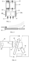
- Fig. 1 shows a schematic illustration of the approach of the invention for a sensor.
- It shows a sensor device comprising an input flow channel 10 for receiving a gas flow 12 with entrained matter to be sensed.
- the gas flow is for example an air flow.
- thermophoretic arrangement is used to induce thermophoretic particle movement from a first, warmer, region 16 of the input flow channel to a second, cooler, region 18 of the input flow channel 10.
- the thermophoretic arrangement comprises a heater 14a and a cooler 14b on opposite sides of the input flow channel 10.
- the first region 16 of the input flow channel couples to a first output flow region 20 and the second region of the input flow channel couples to a second output flow region 22.
- a sensor 24 has a particle sensor component in the first output flow region 20, namely downstream of the first region 16 of the input flow channel.
- Fig. 1 shows the whole sensor in the first output flow region 20, but parts of the sensor may be remote as will be clear from examples below.
- thermophoretic force acts only on a limited distance that depends on the thermal gradient.
- the distance between heater-cooler and the sensor entrance will be known for a particular implementation and impacts the gas density, which will change due to the temperature change. This can and needs to be corrected for in the processing of the sensor signals, as a changed density will lead to the indication of different sensor values.
- the air flow to the sensor entrance can be divided into a number of small sub-channels of the appropriate dimensions. Within each sub-channel the air flow can then be divided into two parts: one with particles that exit through a channel outside the sensor entrance and one with particles removed that enters the sensor. Within the sub-channels, thermophoresis can be used to push the particles to the exhaust channel. An example is given below.
- the inflow of particles into the device housing can be controlled by placing a heated grid at the air inlet.
- the mesh size of the grid may for example be of the order of 0.5 mm.
- Thermophoresis at the heated grid will then block a proportion of the particles from entering the housing or compartment, while allowing gas molecules to pass. This may for example be desired for gas sensors, where it is desired to prevent particles from entering the gas sensor at all.
- such grids might be used to control the portion of particles entering the sensor. For example, decreasing the temperature of the grid will allow a larger portion of particles to enter. Increasing the mesh size will have a similar result.
- the accuracy of certain particle sensors can be maintained through a wider range of particle concentrations, provided that changes in the resulting gas densities are known accurately.
- the heating element can be positioned close to the sensing element of the sensor and used to push the particles away to avoid direct contact with the sensing surface. There is no need to push the particles far from the surface, just enough to avoid direct contact.
- Fig. 2 shows a heater 30 having a heating surface which lies in the same plane as the sensing surface of a sensor 32.
- the sensor is downstream of the heater. The effect of the heating is to lift the gas flow away from the sensor surface, to reduce contamination of the sensor surface.
- Fig. 3 shows an example in which there is a gas flow 40 from an inlet 41 to an outlet 42 of the overall sensor device.
- An infrared LED 44 is used to illuminate the gas flow to enable optical detection of entrained particles based on optical measurements of scattering or reflection.
- the optical sensor 46 comprises a photodiode sensor 48 and a focusing lens 50.
- a heating element By placing a heating element before the lens 50 (in the direction of air flow) or by directly heating the lens, the particles can be prevented from directly touching the lens.
- the lens may be formed as a transparent material with high thermal conductivity such as sapphire and it may then be in direct contact with a heating element (e.g. a resistive heating element).
- a heating element e.g. a resistive heating element
- garnet lenses or lenses produced of other inorganic materials with cubic crystal structure may be used (these being minerals classes that can also be man-made). Such materials are used in view of their large refractive index, and they may also possess high thermal conductivity. These lenses can be made using a ceramic process, and it is possible to incorporate thin heating wires within such lens designs.
- the lens 50 of the optical sensor 46 is covered by a lens cover.
- the lens cover may be optically transparent and electrically conductive. By heating the lens cover, e.g. by applying a voltage to it, the temperature of the lens increases thereby reducing or preventing particle precipitation on the lens.
- the lens cover is fabricated from an optical transparent material that is electrically conductive.
- the lens cover may comprise fine conductive particles that do not disturb optical signals propagating through the lens cover.
- the material of the lens cover may comprise InO2, (In,Sn)O2; ZnO:Ga or ZnO:Ga, graphene or other materials like PEDOT.
- the material of the lens cover is adapted to absorb less than 50% of light originating from illuminated particles of interest.
- the material of the lens cover is adapted to absorb less than 30% of light originating from illuminated particles of interest. More preferably, the material of the lens cover is adapted to absorb less than 20% of light originating from illuminated particles of interest.
- the input flow channel 40 has a first, warmer, region 53 and a second, cooler, region 54.
- the sensor component in this example is the lens 50 which is located in the warmer region 53 of the input flow channel, rather than further downstream.
- the heating has an effect at least a short distance before the input flow channel reaches the sensor component, so that the thermophoretic effect can function.
- the sensor component is downstream of the part of the input flow channel at which heating is first effective, even if the heater is integrated into the sensor component itself. In particular, there will be a thermal gradient away from the heater which will be met by the incoming entrained matter before it reaches the component itself.
- Fig. 3 also shows a separate heater 52 for inducing convective flow through the sensor device.
- a resistive heater may be used to directly heat the lens material or a lens cover as mentioned above, but alternatives include near infra-red heating and ultrasonic heating.
- the heating method of course should not interfere with the operation of the sensor.
- Peltier elements can be electrically switched between heating and cooling, for example allowing the direction of particle movement to be reversed. They also enable simple implementation of heating and cooling on opposite sides of the input flow channel.
- Controlled switching between heating and cooling enables dynamic operation of the system, giving additional accuracy by mass estimation of the particles. This is discussed further below. Similar arguments hold for controlled heating steps.
- thermophoresis force is proportional to the temperature gradient and the inverse of the mean air temperature.
- the heat supplied must be sufficient to generate the force necessary to move the particles.
- Increased air temperature requires a larger temperature gradient to achieve the same effect, therefore the heat applied may be varied based on the ambient temperature.
- a fixed heating level may be selected to ensure the desired result within an expected or operating temperature range. The heating level will for example depend on the area and length of the heating element, which thus depend on the expected particle density and required distance to displace the particles.
- thermophoretic force (with a realistic temperature gradient) may not be able to displace the particles sufficiently far to remove them from the path of the sensor component to be protected.
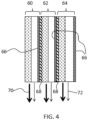
- Fig. 4 shows a grid of three separate sub-channels 60, 62, 64.
- Each sub-channel comprises its own heater 66, and there is thermal insulation 68 between the channels.
- the input flow channel is divided into input sub-channels, each sub-channel having a respective heating arrangement thereby to generate respective first and second regions of the input sub-channel.
- Fig. 4 shows a cross section in plain view, i.e. and the lengths of the sub-channels shown are in the general direction of the overall air flow.
- An end view, i.e. the front face as seen by the air flow, may then comprise a two dimensional or three dimensional array of grid openings, each one corresponding to one of the sub-channels.
- each input sub-channel causes a flow (shown by bold arrows 70) where there is a relatively high concentration of particles and a flow (shown by faint arrows 72) where there is a relatively low concentration of particles.
- the flow 70 will lead to an exhaust port, completely bypassing the sensor in the case of a gas sensor, or else it will lead to the particle detection area in the case of a particle sensor, but away from components of the sensor which are to be protected from contamination. These components are in the path of the flow 72.
- the sub-channel first regions together couple to the first output flow region and the sub-channel second regions together couple to the second output flow region.
- the required channel coupling arrangement is not shown in Fig. 4 .
- Sufficient insulating material 68 is used to separate the channels to avoid both sides of the surrounded channels (i.e. the middle channel and right in this example) becoming heated. If the sensor is used continuously, then over time the internal components will nevertheless reach thermal equilibrium. This can be prevented by using a pulsed or sequential operation, which is practical for a consumer solution, or by active cooling of the cold surface.
- a variation is to use a single narrow channel that is wide at the separation region of the input flow channel but narrow (or funnel like) at the entrance to the sensor.
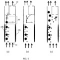
- Fig. 5 shows how the arrangement may be used to enable particle size selection.
- a space 80 is provided between the first region 16 of the input flow channel 10, after the heating / cooling arrangement 14a, 14b, and the first output flow region 20 where the sensor 24 is located. This space is used in this example to allow diffusion of particles.
- thermophoresis driven by the heating arrangement 14a, 14b. All particles are accelerated to a certain forward velocity by the air flow.
- thermophoretic force is no longer acting, but they keep their velocity in the forward (y axis) direction due to the air flow.
- concentration gradient then forces the particles in the transverse (x axis).
- D k ⁇ T ⁇ C c 3 ⁇ ⁇ ⁇ ⁇ ⁇ d p m 2 / s
- Fig. 5(a) shows the movement of larger particles in the inlaid graph
- Fig. 5(b) shows the movement of smaller particles in the inlaid graph.
- the space 80 can in this way be used as a low-pass filter, since it only allows particles below a certain size to enter the sensor.
- the threshold of this filter can be tuned, for example by changing the length of the space 80 or by controlling the air velocity.
- Fig. 5(c) shows the resulting particle distribution and shows how the larger particles are diverted away from the sensor.
- thermophoresis to create the desired particle movement has been assessed using modeling.
- clay particles are modeled in air through a 10 mm wide and 0.5 mm high channel (in cross section) and with 10 mm length. A gas flow of 10 ml/minute is used.
- thermophoretic effect is modeled with heating temperatures of 40 degrees, 60 degrees and 100 degrees on the heated side and 21 degrees at the opposite side.
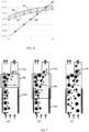
- Fig. 6 shows the results, as a plot of the force acting on the particles (y-axis) as a function of the particle size (x-axis).
- Plot 90 is for the 100 degree heating
- plot 92 is for the 60 degree heating
- plot 94 is for the 40 degree heating.
- Plot 96 shows the gravity force.
- the gravity force becomes dominant.
- the larger the temperature gradient the larger the particle sizes that can be moved using the thermophoretic effect.
- the gravity force overtakes the thermophoretic force at particle sizes of 3.0, 4.0 and 5.4 ⁇ m for the three temperature gradients.
- Figs. 5 and 6 show how the level of heating (or more particularly the thermal gradient) influences the way particles of different size (or mass) behave.
- the level of heating can thus be used as a control parameter.
- a series of sensor measurements can be processed to derive particle concentration information as a function of particle size.
- This particle size (or mass) dependent movement may be controlled by controlling a heating element, or by controlling cooperating heating and cooling elements. If a heating element is switchable between heating and cooling, as is the case for a Peltier heating element, the particle direction may be reversed. For example all particles may be progressively drawn from one side to the other, and in a different sequence they may all be progressively drawn from the other side to the one side. This provides further sensor information which may be used to increase the accuracy of particle sensing as a function of particle size.
- Fig. 7 is a variation of Fig. 5 and illustrates an embodiment where the thermophoretic arrangement 14a, 14b combined with the space 80 forms a prefilter for the sensor 24.
- the prefilter can be tuned by varying the length of the space 80 by partially switching on or off segments of the heater 14a.
- Fig. 7(a) the entire heater 14a is switched on, and only small particles reach the sensor 24.
- Fig. 7(b) only a lower part of the heater 14a is switched on, and as a result the space 80 becomes larger and also medium size particles reach the sensor 24.
- Fig. 7(c) no segment of the heater 14a is switched on, as a result the space 80 becomes even larger and also large particles reach the sensor 24.
- the entire heater 14a may be placed at a larger distance from the sensor 24 by moving the sensor 24 and/or the heater 14a, thereby increasing the length of the space 80.
- the pre-filter gives a user control over which particle sizes can reach the sensor. It is an advantage of the invention that the pre-filter does not get blocked. This extends the life-time of the particle filter.
- the heater 30 may be implemented by any intentional design features which increase the surface temperature.
- the optical component may be at the surface of the packaging of a system. If the system includes a component which gives out a significant amount of heat (such as light source or a high power semiconductor component), the device packaging may be designed to provide thermal coupling between the heat-generating component and the package surface. This also helps with thermal stabilization of the heat generating component (e.g. the light source) and also provides a heated surface for performing a thermophoresis function. The heat-generating component then has a main function (e.g. giving out light) which is a non-heating function.
- a main function e.g. giving out light
- an active heat source may be used for example a wire grid for Joule heating.
- a Peltier heating element is also possible, although this may increase the complexity more than is desired.
- the approach may for example be used in a TO-5 package to heat an optical output window forming a cap at the package surface.
- TO-5 is a designation for a standardized metal semiconductor package used for transistors and some integrated circuits.
- TO stands for "transistor outline" and refers to a series of technical drawings produced by JEDEC. Building a thermal link between the back end of the active component (inside the package) and the cap will help keep the optical window clean. In a similar fashion, active heating may be used.
- the invention can be applied to air purifiers with sensors or to standalone air sensors.
- the heating is to drive particles away from a component, and that component is thus on the heated side.
- this may be only one mode of operation of the device.
- the heating direction may be alternated.
- the device may have one mode where the component is on the hot side and one mode where the component in on the cold side.
- there may be a mode of operation in which the component is protected, and another mode of operation for a particular sensing function or sensing sequence.
Description
- This invention relates to a sensor device and method for detecting targets within a gas flow, such as particulate matter.
-
DE102008041809 discloses a method for operating a particle sensor. In a phase in which no measurements take place, a heater is set to a temperature to avoid particle deposition at electrodes used for particle measurement. Avoiding particle deposition can, for example, be based on thermophoresis. - Airborne particle pollution, especially particle matter size less than 2.5 µm diameter range (named "PM2.5"), is a big concern for countries like China, where the speed of industrialization stretches the boundaries of regulatory requirements.
- As a consequence of increasing consumer empowerment, the demand for information about the air quality of living spaces is increasing. Especially in China, excessive PM2.5 pollution has become a common problem in the last decade. This problem is also validated by continuous measurements in various Chinese cities. The data is publicly available and can be simultaneously monitored by mobile phone applications or through the web.
- Availability of this data as well as continuous national and international media attention has created strong consumer awareness about the problem.
- Official outdoor air quality standards define particle matter concentration as mass concentration per unit volume (e.g. µg/m3). The average PM2.5 pollution concentration in mainland China has been calculated based on satellite data, and it has been found that the majority of the country exceeds the World Health Organization limits of 10 µg/m3, with some regions reaching and even exceeding PM2.5 concentrations of 100 µg/m3.
- Standard reference measurement methods are based on measuring the mass of deposited or captured particles per air sampling volume for example using a quartz crystal microbalance, a tapered resonator, an impactor, or weighing filters and sieves. There is also a desire to detect specific chemicals within the air, in addition to (or instead of) measuring particle concentrations.
- For many sensors, the operation principles result in a response to other compounds than the target compound, leading to incorrect readings when a target compound and an interfering compound are present simultaneously.
- Taking an electrochemical formaldehyde sensor as example, compounds like alcohols and detergents can greatly influence the output, and these other compounds are commonly seen in real home conditions.
- A known solution is to put a physical filter in front of the sensor to block suspended solids and liquids, however, over time this filter will get blocked and reduce the air flow through the sensor.
-
GB2319191A -
US2009019918A1 discloses a procedure for operating a collecting particle sensor, which is provided with measuring phases, during which particles that are contained in an off-gas stream accumulate on a measuring route, and a device for implementing this procedure are submitted. Protection phases are provided, during which at least one measure for diminishing the accumulation of particles on the measuring route is adopted. -
DE102008041809A1 discloses a resistive particle sensor for detecting conductive particles in a gas stream, a method for its operation and a method for its production. The disclosure describes an electrode arrangement for sensing particles. -
US2006066834A1 discloses an apparatus for and method of handling a reticle in a lithography system, such as an extreme ultraviolet lithography system. In particular, a thermophoretic system for protecting such a reticle is disclosed. - It is an object of this invention to provide the benefit of pre-filtering (e.g. removal of most suspended solids/liquids) without the need for a physical filter that can become blocked. This pre-filtering function may also be used to selectively protect key components of the sensors. The invention is defined by the
independent claims 1 and 12. The dependent claims define advantageous embodiments. - According to the invention, there is provided a particle sensor, according to claim 1, comprising:
- an input flow channel for receiving a gas flow with entrained matter to be sensed;
- a heating arrangement to induce thermophoretic particle movement from a first, warmer, region of the input flow channel to a second, cooler, region of the input flow channel;
- a sensor comprising a particle sensor component downstream of the first region of the input flow channel.
- This arrangement uses thermophoretic induced movement of entrained matter, in particular particles, to steer matter away from a particle sensor component. In this way it can be controlled which particles are sensed by the particle sensor component.
- The heating arrangement may comprise a Peltier heater. This provides an efficient and low cost implementation. The heating arrangement may comprise a thermal coupling between an existing heat-generating component of the system which is provided to perform a non-heating function. For example, a light source generates heat in addition to its main function of generating light. This heat can be coupled to the component to be protected to drive particulate matter away. Alternatively, an active heat source may be provided on or adjacent the component. This may for example be a Joule heating wire grid.
- The device may further comprise a cooling arrangement which combines with the heating arrangement to induce the thermophoretic particle movement. This enables more active thermophoretic behavior. The cooling arrangement may also comprise a Peltier device, functioning as a cooler.
- The sensor may comprise an optical sensor, and the sensor component comprises a lens or lens cover. The sensor does not need to be in direct contact with the entrained matter since the optical detection can be remote. The heating arrangement may for example be integrated with the lens.
- If a sensor component of the optical sensor comprises a lens cover, the lens cover may be optically transparent and electrically conductive. For example, the lens cover may be fabricated from a material that is optically transparent and electrically conductive. The device or the optical sensor may further comprise a means for applying a voltage to the lens cover such that the lens cover heats up during operation. For example, a voltage supply unit adapted for delivering a applying a suitable voltage.
- The first region of the input flow channel couples to a first output flow region and the second region of the input flow channel couples to a second output flow region. The sensor component may then be located in the first output flow region.
- Note that the term "couples", for example in the expression "A couples to B", is used to mean that the B is positioned downstream of A when following the prevailing general flow direction. Thus, it does not imply any particular physical channels, but may be achieved only with suitable relative positioning of components.
- Thus, in accordance with the invention, the sensor component is further downstream at a corresponding warmer part of the output flow region.
- The entrained matter is moved from the relatively warmer region to the relatively cooler region by the thermophoresis, and the sensor component is thus located at a region which has a lower concentration of the entrained matter.
- If the input flow channel is large, the thermophoretic effect may be reduced. The input flow channel may then be divided into input sub-channels, each sub-channel having a respective heating arrangement thereby to generate respective first (warmer) and second (cooler) regions of the input sub-channel. The sub-channel first regions may then together couple to the first output flow region and the sub-channel second regions may then together couple to the second output flow region.
- This enables the entrained matter to be moved more effectively between the output flow regions.
- According to an embodiment of the invention, a space is provided in between the first region and the sensor. The space is provided between the first region of the input flow channel, after the thermophoretic arrangement, and the first output flow region at which the sensor or sensor component is located. This space enables diffusion to take place before sensing. This diffusion is dependent on particle size, so particle filtering takes place before sensing.
- According to an embodiment of the invention, a means for changing a length of the space between the first region of the input flow channel and the sensor is present.
- According to a particular embodiment of the invention, the thermophoretic arrangement comprises a segmented heating arrangement for inducing the thermophoretic particle movement. The means for changing a length of the space is configured to activate one or more segments of the segmented heating arrangement thereby changing the length of the space. For example, by applying a voltage to one or more segments, the length of the space between the first region of the input flow channel and the sensor changes depending on how many segments are supplied with a voltage. For example, the means for changing a length of the space may comprise de-multiplexing logic to activate appropriate segments. The de-multiplexing logic may be driven by a processor that can be programmed by the user.
- According to another particular embodiment of the invention, the sensor and the thermophoretic arrangement are moveable relative to each other. The means for changing a length of the space allows increasing or decreasing the space by moving the thermophoretic arrangement and the sensor relative to each other. For example, a mechanical structure may be provided which features the sensor and the thermophoretic arrangement and which allows the distance between the two elements to be changed.
- The device may for example be used for sensing a target in air, and the sensor may for example include a volatile organic compound (VOC) sensor in addition to a particle sensor. Thus the "entrained matter" may be gaseous or particulate.
- According to the invention, there is provided a sensing method, according to
claim 12, comprising: - receiving a gas flow with entrained matter to be sensed at an input flow channel;
- prefiltering the gas flow by inducing a thermophoretic particle movement from a first, warmer, region of the input flow channel to a second, cooler, region of the input flow channel; and
- performing sensing using a sensor which comprises a particle sensor component downstream of the first region of the input flow channel.
- The sensing is based on the matter present downstream of the first region. Alternatively, the sensing may be based on matter present in or downstream of the second region, but there is nevertheless a sensor component in or downstream of the first region.
- The method may comprise cooling the gas flow in the input flow channel at a different location to the heating, wherein the heating and cooling combine to induce the thermophoretic particle movement.
- The method may be used for sensing VOCs in addition to a particulate matter in air.
- These and other aspects of the invention will be apparent from and elucidated with reference to the embodiments described hereinafter.
- Examples of the invention will now be described in detail with reference to the accompanying drawings, in which:
-
Fig. 1 shows an example of a gas sensor; -
Fig. 2 shows how the thermophoretic effect may be used to lift a particulate flow away from a sensor surface; -
Fig. 3 shows an optical gas sensor; -
Fig. 4 shows how a flow can be divided into sub-channels; -
Fig. 5 shows how the thermophoretic effect may be used for a particle filtering approach; -
Fig. 6 shows results of modeling the electrophoretic force acting on particles of different sizes; and -
Fig. 7 shows how the prefiltering can be tuned. - The invention provides a system comprising a particle sensing component, and a heating arrangement to induce thermophoretic particle movement away from the component. This mechanism may be used in a sensor device which comprises an input flow channel for receiving a gas flow with entrained matter to be sensed. The heating arrangement is used to induce thermophoretic particle movement from a first, warmer, region of the input flow channel to a second, cooler, region of the input flow channel. A sensor comprises the particle sensor component) downstream of the first region of the input flow channel. This way, filtering can be perfomed without the need for a physical filter.
- In this sensor device, thermophoresis is used to move particles from the air path of sensors or key components of such sensors. In doing so, the sensor or specific components thereof can be protected without the need for a physical filter to block particles.
- The force which is induced during thermophoresis depends on the temperature gradient in the gas around the particles and also the temperature gradient within the particles themselves (which depends on the thermal conductivity of the particle). Generally, thermophoresis is a force that affects particles in air and is proportional to the thermal gradient in the air. The gas molecules on the hot side exert a force on the particles, pushing them to the cold side.
- To generate the thermophoretic force, a heater can be used. Particles entrained within a gas flow will then be pushed away from the heated surface. To increase the temperature gradient, a cooling element and/or a cold surface with a large thermal mass (e.g. a heat sink) may be placed opposite. Both heating and cooling can be implemented using thermally active components (e.g. Peltier elements).
- An alternative is to use an existing hot component of the sensor system. For example a pre-concentrator may generate heat which may be used, and the column section of a micro gas chromatography unit also generates usable heat. The hot components can also be used for facilitating a continuous convection air stream to the sensor compartment.
- Examples of the invention applied to sensor devices will first be described.
-
Fig. 1 shows a schematic illustration of the approach of the invention for a sensor. - It shows a sensor device comprising an
input flow channel 10 for receiving agas flow 12 with entrained matter to be sensed. The gas flow is for example an air flow. - A thermophoretic arrangement is used to induce thermophoretic particle movement from a first, warmer,
region 16 of the input flow channel to a second, cooler,region 18 of theinput flow channel 10. In the example shown, the thermophoretic arrangement comprises aheater 14a and a cooler 14b on opposite sides of theinput flow channel 10. - The
first region 16 of the input flow channel couples to a firstoutput flow region 20 and the second region of the input flow channel couples to a secondoutput flow region 22. - A
sensor 24 has a particle sensor component in the firstoutput flow region 20, namely downstream of thefirst region 16 of the input flow channel.Fig. 1 shows the whole sensor in the firstoutput flow region 20, but parts of the sensor may be remote as will be clear from examples below. - The particles in the gas flow are pushed away from the heating element and thus away from the sensor input. In practice, the thermophoretic force acts only on a limited distance that depends on the thermal gradient.
- The distance between heater-cooler and the sensor entrance will be known for a particular implementation and impacts the gas density, which will change due to the temperature change. This can and needs to be corrected for in the processing of the sensor signals, as a changed density will lead to the indication of different sensor values.
- For sensors with larger air flow entrances, the air flow to the sensor entrance can be divided into a number of small sub-channels of the appropriate dimensions. Within each sub-channel the air flow can then be divided into two parts: one with particles that exit through a channel outside the sensor entrance and one with particles removed that enters the sensor. Within the sub-channels, thermophoresis can be used to push the particles to the exhaust channel. An example is given below.
- The inflow of particles into the device housing (or into sub-compartments within a device) can be controlled by placing a heated grid at the air inlet. The mesh size of the grid may for example be of the order of 0.5 mm. Thermophoresis at the heated grid will then block a proportion of the particles from entering the housing or compartment, while allowing gas molecules to pass. This may for example be desired for gas sensors, where it is desired to prevent particles from entering the gas sensor at all.
- In other cases, such grids might be used to control the portion of particles entering the sensor. For example, decreasing the temperature of the grid will allow a larger portion of particles to enter. Increasing the mesh size will have a similar result.
- By reducing the portion of particles entering the housing, the accuracy of certain particle sensors can be maintained through a wider range of particle concentrations, provided that changes in the resulting gas densities are known accurately.
- In an alternative approach, the heating element can be positioned close to the sensing element of the sensor and used to push the particles away to avoid direct contact with the sensing surface. There is no need to push the particles far from the surface, just enough to avoid direct contact.
-
Fig. 2 shows aheater 30 having a heating surface which lies in the same plane as the sensing surface of asensor 32. The sensor is downstream of the heater. The effect of the heating is to lift the gas flow away from the sensor surface, to reduce contamination of the sensor surface. -
Fig. 3 shows an example in which there is agas flow 40 from aninlet 41 to anoutlet 42 of the overall sensor device. Aninfrared LED 44 is used to illuminate the gas flow to enable optical detection of entrained particles based on optical measurements of scattering or reflection. - The
optical sensor 46 comprises aphotodiode sensor 48 and a focusinglens 50. By placing a heating element before the lens 50 (in the direction of air flow) or by directly heating the lens, the particles can be prevented from directly touching the lens. - For example, the lens may be formed as a transparent material with high thermal conductivity such as sapphire and it may then be in direct contact with a heating element (e.g. a resistive heating element).
- So-called garnet lenses or lenses produced of other inorganic materials with cubic crystal structure may be used (these being minerals classes that can also be man-made). Such materials are used in view of their large refractive index, and they may also possess high thermal conductivity. These lenses can be made using a ceramic process, and it is possible to incorporate thin heating wires within such lens designs.
- According to an embodiment of the invention, the
lens 50 of theoptical sensor 46 is covered by a lens cover. The lens cover may be optically transparent and electrically conductive. By heating the lens cover, e.g. by applying a voltage to it, the temperature of the lens increases thereby reducing or preventing particle precipitation on the lens. According to a particular embodiment, the lens cover is fabricated from an optical transparent material that is electrically conductive. For example, the lens cover may comprise fine conductive particles that do not disturb optical signals propagating through the lens cover. The material of the lens cover may comprise InO2, (In,Sn)O2; ZnO:Ga or ZnO:Ga, graphene or other materials like PEDOT. According to an embodiment of the invention, the material of the lens cover is adapted to absorb less than 50% of light originating from illuminated particles of interest. Preferably, the material of the lens cover is adapted to absorb less than 30% of light originating from illuminated particles of interest. More preferably, the material of the lens cover is adapted to absorb less than 20% of light originating from illuminated particles of interest. - In this way, the
input flow channel 40 has a first, warmer,region 53 and a second, cooler,region 54. The sensor component in this example is thelens 50 which is located in thewarmer region 53 of the input flow channel, rather than further downstream. Preferably, the heating has an effect at least a short distance before the input flow channel reaches the sensor component, so that the thermophoretic effect can function. Thus, even in this case, the sensor component is downstream of the part of the input flow channel at which heating is first effective, even if the heater is integrated into the sensor component itself. In particular, there will be a thermal gradient away from the heater which will be met by the incoming entrained matter before it reaches the component itself. -
Fig. 3 also shows aseparate heater 52 for inducing convective flow through the sensor device. - In general, many methods can be used to heat the lens. A resistive heater may be used to directly heat the lens material or a lens cover as mentioned above, but alternatives include near infra-red heating and ultrasonic heating. The heating method of course should not interfere with the operation of the sensor.
- One example of a heating element is a Peltier heating element. Peltier elements can be electrically switched between heating and cooling, for example allowing the direction of particle movement to be reversed. They also enable simple implementation of heating and cooling on opposite sides of the input flow channel.
- Controlled switching between heating and cooling enables dynamic operation of the system, giving additional accuracy by mass estimation of the particles. This is discussed further below. Similar arguments hold for controlled heating steps.
- The thermophoresis force is proportional to the temperature gradient and the inverse of the mean air temperature. For a given configuration, the heat supplied must be sufficient to generate the force necessary to move the particles. Increased air temperature requires a larger temperature gradient to achieve the same effect, therefore the heat applied may be varied based on the ambient temperature. Alternatively, a fixed heating level may be selected to ensure the desired result within an expected or operating temperature range. The heating level will for example depend on the area and length of the heating element, which thus depend on the expected particle density and required distance to displace the particles.
- As explained above, if the sensor entrance is too large, the thermophoretic force (with a realistic temperature gradient) may not be able to displace the particles sufficiently far to remove them from the path of the sensor component to be protected.
-
Fig. 4 shows a grid of threeseparate sub-channels own heater 66, and there isthermal insulation 68 between the channels. In this way, the input flow channel is divided into input sub-channels, each sub-channel having a respective heating arrangement thereby to generate respective first and second regions of the input sub-channel. -
Fig. 4 shows a cross section in plain view, i.e. and the lengths of the sub-channels shown are in the general direction of the overall air flow. An end view, i.e. the front face as seen by the air flow, may then comprise a two dimensional or three dimensional array of grid openings, each one corresponding to one of the sub-channels. - In
Fig. 4 , each input sub-channel causes a flow (shown by bold arrows 70) where there is a relatively high concentration of particles and a flow (shown by faint arrows 72) where there is a relatively low concentration of particles. Theflow 70 will lead to an exhaust port, completely bypassing the sensor in the case of a gas sensor, or else it will lead to the particle detection area in the case of a particle sensor, but away from components of the sensor which are to be protected from contamination. These components are in the path of theflow 72. - The sub-channel first regions together couple to the first output flow region and the sub-channel second regions together couple to the second output flow region. The required channel coupling arrangement is not shown in
Fig. 4 . - Particles will move from the heated side to concentrate the particles in the exhaust streams. Sufficient insulating
material 68 is used to separate the channels to avoid both sides of the surrounded channels (i.e. the middle channel and right in this example) becoming heated. If the sensor is used continuously, then over time the internal components will nevertheless reach thermal equilibrium. This can be prevented by using a pulsed or sequential operation, which is practical for a consumer solution, or by active cooling of the cold surface. - A variation is to use a single narrow channel that is wide at the separation region of the input flow channel but narrow (or funnel like) at the entrance to the sensor.
-
Fig. 5 shows how the arrangement may be used to enable particle size selection. - In the arrangement of
Fig. 5 , aspace 80 is provided between thefirst region 16 of theinput flow channel 10, after the heating /cooling arrangement output flow region 20 where thesensor 24 is located. This space is used in this example to allow diffusion of particles. - As shown in
Fig. 5(a) , all particles are first concentrated at one side of theinput flow region 10 by thermophoresis driven by theheating arrangement - Once they leave the
input flow region 10 and enter thespace 80, the thermophoretic force is no longer acting, but they keep their velocity in the forward (y axis) direction due to the air flow. The concentration gradient then forces the particles in the transverse (x axis). - This diffusion is dependent on the particle size.
- In particular, the particle diffusion is dependent on the size and shape of the aerosol particles, resulting in slower diffusion of larger particles than smaller ones:

- D is the particle diffusion coefficient
- k is the Boltzman constant
- T is the temperature
- Cc is the Cunningham slip correction factor
- η is the gas viscosity
- dp is the particle diameter.
- As a result, smaller particles will experience a stronger deviation in the x-axis direction compared to larger ones.
Fig. 5(a) shows the movement of larger particles in the inlaid graph, andFig. 5(b) shows the movement of smaller particles in the inlaid graph. - The
space 80 can in this way be used as a low-pass filter, since it only allows particles below a certain size to enter the sensor. - The threshold of this filter can be tuned, for example by changing the length of the
space 80 or by controlling the air velocity. -
Fig. 5(c) shows the resulting particle distribution and shows how the larger particles are diverted away from the sensor. - The ability for thermophoresis to create the desired particle movement has been assessed using modeling. For this purpose, clay particles are modeled in air through a 10 mm wide and 0.5 mm high channel (in cross section) and with 10 mm length. A gas flow of 10 ml/minute is used.
- The thermophoretic effect is modeled with heating temperatures of 40 degrees, 60 degrees and 100 degrees on the heated side and 21 degrees at the opposite side.
-
Fig. 6 shows the results, as a plot of the force acting on the particles (y-axis) as a function of the particle size (x-axis).Plot 90 is for the 100 degree heating,plot 92 is for the 60 degree heating andplot 94 is for the 40 degree heating.Plot 96 shows the gravity force. - It can be seen that at a certain particle size, the gravity force becomes dominant. The larger the temperature gradient, the larger the particle sizes that can be moved using the thermophoretic effect. In this simulation, the gravity force overtakes the thermophoretic force at particle sizes of 3.0, 4.0 and 5.4 µm for the three temperature gradients.
-
Figs. 5 and6 show how the level of heating (or more particularly the thermal gradient) influences the way particles of different size (or mass) behave. The level of heating can thus be used as a control parameter. By progressively increasing the size range of particles drawn away from the particle sensor, a series of sensor measurements can be processed to derive particle concentration information as a function of particle size. - This particle size (or mass) dependent movement may be controlled by controlling a heating element, or by controlling cooperating heating and cooling elements. If a heating element is switchable between heating and cooling, as is the case for a Peltier heating element, the particle direction may be reversed. For example all particles may be progressively drawn from one side to the other, and in a different sequence they may all be progressively drawn from the other side to the one side. This provides further sensor information which may be used to increase the accuracy of particle sensing as a function of particle size.
-
Fig. 7 is a variation ofFig. 5 and illustrates an embodiment where thethermophoretic arrangement space 80 forms a prefilter for thesensor 24. The prefilter can be tuned by varying the length of thespace 80 by partially switching on or off segments of theheater 14a. InFig. 7(a) , theentire heater 14a is switched on, and only small particles reach thesensor 24. InFig. 7(b) , only a lower part of theheater 14a is switched on, and as a result thespace 80 becomes larger and also medium size particles reach thesensor 24. InFig. 7(c) , no segment of theheater 14a is switched on, as a result thespace 80 becomes even larger and also large particles reach thesensor 24. In an alternative prefilter tuning example, theentire heater 14a may be placed at a larger distance from thesensor 24 by moving thesensor 24 and/or theheater 14a, thereby increasing the length of thespace 80. The pre-filter gives a user control over which particle sizes can reach the sensor. It is an advantage of the invention that the pre-filter does not get blocked. This extends the life-time of the particle filter. - The detailed examples above all relate to sensor applications.
- The
heater 30 may be implemented by any intentional design features which increase the surface temperature. For example, the optical component may be at the surface of the packaging of a system. If the system includes a component which gives out a significant amount of heat (such as light source or a high power semiconductor component), the device packaging may be designed to provide thermal coupling between the heat-generating component and the package surface. This also helps with thermal stabilization of the heat generating component (e.g. the light source) and also provides a heated surface for performing a thermophoresis function. The heat-generating component then has a main function (e.g. giving out light) which is a non-heating function. - Alternatively, an active heat source may be used for example a wire grid for Joule heating. A Peltier heating element is also possible, although this may increase the complexity more than is desired. The approach may for example be used in a TO-5 package to heat an optical output window forming a cap at the package surface. In electronics, TO-5 is a designation for a standardized metal semiconductor package used for transistors and some integrated circuits. TO stands for "transistor outline" and refers to a series of technical drawings produced by JEDEC. Building a thermal link between the back end of the active component (inside the package) and the cap will help keep the optical window clean. In a similar fashion, active heating may be used.
- The invention can be applied to air purifiers with sensors or to standalone air sensors.
- In examples of the invention, the heating is to drive particles away from a component, and that component is thus on the heated side. However, this may be only one mode of operation of the device. As explained above, the heating direction may be alternated. In this case, the device may have one mode where the component is on the hot side and one mode where the component in on the cold side. Thus, there may be a mode of operation in which the component is protected, and another mode of operation for a particular sensing function or sensing sequence.
- Other variations to the disclosed embodiments can be understood and effected by those skilled in the art in practicing the claimed invention, from a study of the drawings, the disclosure, and the appended claims. In the claims, the word "comprising" does not exclude other elements or steps.
- Any reference signs in the claims should not be construed as limiting the scope.
Claims (14)
- A particle sensor comprising:an input flow channel (10) for receiving a gas flow with entrained matter to be sensed;a thermophoretic arrangement (14a, 14b) to induce a thermophoretic particle movement from a first region (16) of the input flow channel (10) to a second region (18) of the input flow channel (10), the first region (16) being warmer than the second region (18); andwherein the first region (16) of the input flow channel (10) couples to a first output flow region (20) and the second region (18) of the input flow channel (10) couples to a second output flow region (22); characterized in that the particle sensor further comprisesa sensor (24) comprising a particle sensor component which is located downstream of the first region (16) of the input flow channel (10) in the first output flow region (20).
- A particle sensor as claimed in claim 1, wherein the thermophoretic arrangement (14a, 14b) comprises a Peltier heater.
- A particle sensor as claimed in claim 1 or 2, wherein the thermophoretic arrangement (14a, 14b) comprises a cooling arrangement (14b) which combines with a heating arrangement (14a) to induce the thermophoretic particle movement, wherein the cooling arrangement (14b) comprises a Peltier cooler.
- A particle sensor as claimed in any one of claims 1 to 3, wherein the sensor (24) comprises an optical sensor (46), wherein a sensor component of the optical sensor (46) comprises a lens (50) or lens cover and wherein the thermophoretic arrangement (14a) is integrated with the lens (50) or lens cover.
- A particle sensor as claimed in any one of claims 1 to 3, wherein the sensor (24) comprises an optical sensor (46), wherein a sensor component of the optical sensor (56) comprises a lens (50), wherein the lens (50) is covered by a lens cover, and wherein the lens cover is optically transparent and electrically conductive.
- A particle sensor as claimed in claim 1, wherein the input flow channel (10) is divided into input sub-channels (60, 62, 64), each sub-channel (60, 62, 64) having a respective heating arrangement (66) thereby to generate respective first (16) and second (18) regions of the input sub-channel (60, 62, 64), wherein the sub-channel first regions together couple to the first output flow region (20) and the sub-channel second regions together couple to the second output flow region (22).
- A particle sensor device as claimed in any preceding claim, wherein a space (80) is provided between the first region (16) of the input flow channel (10), after the heating arrangement, and the first output flow region (20).
- A particle sensor as claimed in claim 7, comprising a means for changing a length of the space (80).
- A particle sensor as claimed in claim 8, wherein the thermophoretic arrangement (14a, 14b) comprises a segmented heating arrangement (14a), and wherein the means for changing a length of the space (80) is configured for activating one or more segments of the segmented heating arrangement (14a) thereby changing the length of the space (80).
- A particle sensor as claimed in claim 8, wherein the sensor (24) and the thermophoretic arrangement (14a, 14b) are moveable relative to each other, and wherein the means for changing a length of the space (80) allows changing the length of the space (80) by moving the thermophoretic arrangement (14a, 14b) and the sensor (24) relative to each other.
- A particle sensor as claimed in any one of claims 1 to 10, which is adapted to sense a volatile organic compound in addition to sensing particles.
- A particle sensing method comprising:receiving a gas flow with entrained matter to be sensed at an input flow channel (10);prefiltering the gas flow by inducing a thermophoretic particle movement from a first region (16) of the input flow channel (10) to a second region (18) of the input flow channel (10), the first region (16) being warmer than the second region (18), and wherein the first region (16) of the input flow channel (10) couples to a first output flow region (20) and the second region (18) of the input flow channel (10) couples to a second output flow region (22); characterized in that the particle sensing method further comprises:
performing sensing using a particle sensor component located downstream of the first region (16) of the input flow channel (10) in the first output flow region (20). - A method as claimed in claim 12, further comprising cooling the gas flow in the input flow channel (10) at a different location to heating the gas flow in the input flow channel (10), wherein the heating and cooling combine to induce the thermophoretic particle movement.
- A method as claimed in any one of claims 12 to 13, comprising heating separately within sub-channels (60, 62, 64) of the input flow channel (10) thereby to generate respective first (16) and second regions (18) with each sub-channel (60, 62, 64), and coupling together the sub-channel first regions to a first output flow region (20) and coupling together the sub-channel second regions to a second output flow region (22).
Applications Claiming Priority (3)
| Application Number | Priority Date | Filing Date | Title |
|---|---|---|---|
| CN2015075276 | 2015-03-27 | ||
| EP15166494 | 2015-05-06 | ||
| PCT/EP2016/055615 WO2016156035A1 (en) | 2015-03-27 | 2016-03-16 | Protecting an optical particle sensor from particulate deposits by thermophoresis |
Publications (2)
| Publication Number | Publication Date |
|---|---|
| EP3274071A1 EP3274071A1 (en) | 2018-01-31 |
| EP3274071B1 true EP3274071B1 (en) | 2023-05-24 |
Family
ID=55650387
Family Applications (1)
| Application Number | Title | Priority Date | Filing Date |
|---|---|---|---|
| EP16713753.8A Active EP3274071B1 (en) | 2015-03-27 | 2016-03-16 | Protecting an optical particle sensor from particulate deposits by thermophoresis |
Country Status (5)
| Country | Link |
|---|---|
| US (1) | US10363514B2 (en) |
| EP (1) | EP3274071B1 (en) |
| JP (1) | JP2018512563A (en) |
| CN (1) | CN107532996B (en) |
| WO (1) | WO2016156035A1 (en) |
Families Citing this family (14)
| Publication number | Priority date | Publication date | Assignee | Title |
|---|---|---|---|---|
| CN107478576B (en) * | 2016-06-07 | 2024-02-20 | 宁波方太厨具有限公司 | Protective structure of oil smoke sensor |
| US10215699B2 (en) * | 2017-01-03 | 2019-02-26 | Honeywell International Inc. | Utilizing updraft flow in a fan-less dust sensor |
| EP3444587A1 (en) * | 2017-08-14 | 2019-02-20 | Koninklijke Philips N.V. | Particle sensor and particle sensing method |
| EP3642587B1 (en) | 2017-06-21 | 2020-12-30 | Koninklijke Philips N.V. | Particle sensor and particle sensing method |
| GB201715014D0 (en) | 2017-09-18 | 2017-11-01 | Cambridge Entpr Ltd | Particulate matter detection |
| US11326991B2 (en) * | 2017-11-14 | 2022-05-10 | Aerodyne Microsystems Inc. | Airborne particle detection with selective thermophoretic particle deflection |
| DE102018219891A1 (en) * | 2018-11-20 | 2020-05-20 | Robert Bosch Gmbh | Method for operating a particle sensor |
| US11828210B2 (en) | 2020-08-20 | 2023-11-28 | Denso International America, Inc. | Diagnostic systems and methods of vehicles using olfaction |
| US11636870B2 (en) | 2020-08-20 | 2023-04-25 | Denso International America, Inc. | Smoking cessation systems and methods |
| US11760169B2 (en) | 2020-08-20 | 2023-09-19 | Denso International America, Inc. | Particulate control systems and methods for olfaction sensors |
| US11813926B2 (en) | 2020-08-20 | 2023-11-14 | Denso International America, Inc. | Binding agent and olfaction sensor |
| US11932080B2 (en) | 2020-08-20 | 2024-03-19 | Denso International America, Inc. | Diagnostic and recirculation control systems and methods |
| US11760170B2 (en) | 2020-08-20 | 2023-09-19 | Denso International America, Inc. | Olfaction sensor preservation systems and methods |
| US11881093B2 (en) | 2020-08-20 | 2024-01-23 | Denso International America, Inc. | Systems and methods for identifying smoking in vehicles |
Citations (2)
| Publication number | Priority date | Publication date | Assignee | Title |
|---|---|---|---|---|
| JPS57131036A (en) * | 1981-02-06 | 1982-08-13 | Rion Co Ltd | Light scattering type floating particle counting |
| US20130036793A1 (en) * | 2011-08-08 | 2013-02-14 | University Of California | Microfabricated particulate matter monitor |
Family Cites Families (29)
| Publication number | Priority date | Publication date | Assignee | Title |
|---|---|---|---|---|
| US4675031A (en) * | 1985-08-19 | 1987-06-23 | Sinnar Abbas M | Phoretic enhanced-gravity particulate removal system |
| US4896047A (en) * | 1988-04-11 | 1990-01-23 | Westinghouse Electric Corp. | Method and apparatus of periodically obtaining accurate opacity monitor readings of an exhaust gas stream |
| GB8818463D0 (en) * | 1988-08-03 | 1988-09-07 | Loughborough Consult Ltd | Apparatus & method for removing particulate matter from exhaust gases of i c engine |
| US5083865A (en) * | 1990-05-11 | 1992-01-28 | Applied Materials, Inc. | Particle monitor system and method |
| JPH0527654U (en) * | 1991-09-19 | 1993-04-09 | 神栄株式会社 | Air pollution detector |
| JPH0676333A (en) * | 1992-08-25 | 1994-03-18 | Mitsubishi Electric Corp | Dust guard for objective lens of optical disk |
| JP3052639B2 (en) * | 1993-02-22 | 2000-06-19 | 株式会社島津製作所 | Particle size distribution analyzer |
| US5463460A (en) * | 1993-07-08 | 1995-10-31 | Applied Materials, Inc. | Particle monitoring sensor |
| GB2319191B (en) * | 1996-11-15 | 2000-09-27 | Boris Zachar Gorbunov | A particulate matter concentrator |
| GB2339398B (en) * | 1998-07-10 | 2002-05-01 | Notetry Ltd | Apparatus and method for concentrating gasborne particles in a portion of a gas stream |
| US20020159215A1 (en) | 1999-12-06 | 2002-10-31 | Siess Harold Edward | Protecting transmissive surfaces |
| ATE428588T1 (en) * | 2004-08-11 | 2009-05-15 | Koninkl Philips Electronics Nv | AIR POLLUTION SENSOR SYSTEM |
| US7477358B2 (en) * | 2004-09-28 | 2009-01-13 | Nikon Corporation | EUV reticle handling system and method |
| US8177142B2 (en) | 2005-08-26 | 2012-05-15 | Ricciardi Jonathan J | Method and apparatus for an improved aerosol generator and associated uses and equipment |
| JP4849626B2 (en) * | 2007-01-16 | 2012-01-11 | 東京エレクトロン株式会社 | Particle monitor system and substrate processing apparatus |
| DE102007014761B4 (en) * | 2007-03-28 | 2022-05-12 | Robert Bosch Gmbh | Method for operating a collecting particle sensor and device for carrying out the method |
| EP2255178A1 (en) * | 2008-02-27 | 2010-12-01 | Volvo Technology Corporation | Method and arrangement for detecting particles |
| DE102008041809A1 (en) * | 2008-09-04 | 2010-03-11 | Robert Bosch Gmbh | Particle sensor, particularly resistive particle sensor for detection of conductive particles in gas stream, comprises two electrode systems with primary electrode and secondary electrode, and ceramic base body |
| DE102009000820A1 (en) | 2009-02-12 | 2010-08-19 | Robert Bosch Gmbh | Sensor element of a gas sensor and method for operating the same |
| WO2011135717A1 (en) * | 2010-04-30 | 2011-11-03 | トヨタ自動車株式会社 | Particulate matter quantity detection apparatus |
| JP2011256796A (en) * | 2010-06-09 | 2011-12-22 | Toyota Motor Corp | Pm quantity detection system |
| JP2012220263A (en) * | 2011-04-05 | 2012-11-12 | Shimadzu Corp | Particle size measuring device |
| US8973447B2 (en) * | 2011-05-24 | 2015-03-10 | Colorado State University Research Foundation | Thermophoretic sampler |
| US20130235357A1 (en) | 2012-03-12 | 2013-09-12 | Kla-Tencor Corporation | System and Method for Particle Control Near A Reticle |
| CN102692368A (en) * | 2012-05-23 | 2012-09-26 | 华北电力大学 | Visual narrow rectangular channel aerosol motion deposition system |
| KR20130134243A (en) * | 2012-05-30 | 2013-12-10 | 연세대학교 산학협력단 | Particle sampling cell and laser measurement system contains the same |
| US9389180B2 (en) * | 2013-02-15 | 2016-07-12 | Kla-Tencor Corporation | Methods and apparatus for use with extreme ultraviolet light having contamination protection |
| CN103349879B (en) * | 2013-07-04 | 2015-05-20 | 清华大学 | Thermophoretic air purifying device and method |
| GB201715014D0 (en) * | 2017-09-18 | 2017-11-01 | Cambridge Entpr Ltd | Particulate matter detection |
-
2016
- 2016-03-16 CN CN201680018709.1A patent/CN107532996B/en active Active
- 2016-03-16 JP JP2017538640A patent/JP2018512563A/en active Pending
- 2016-03-16 EP EP16713753.8A patent/EP3274071B1/en active Active
- 2016-03-16 US US15/557,492 patent/US10363514B2/en active Active
- 2016-03-16 WO PCT/EP2016/055615 patent/WO2016156035A1/en active Application Filing
Patent Citations (2)
| Publication number | Priority date | Publication date | Assignee | Title |
|---|---|---|---|---|
| JPS57131036A (en) * | 1981-02-06 | 1982-08-13 | Rion Co Ltd | Light scattering type floating particle counting |
| US20130036793A1 (en) * | 2011-08-08 | 2013-02-14 | University Of California | Microfabricated particulate matter monitor |
Also Published As
| Publication number | Publication date |
|---|---|
| JP2018512563A (en) | 2018-05-17 |
| EP3274071A1 (en) | 2018-01-31 |
| CN107532996A (en) | 2018-01-02 |
| US10363514B2 (en) | 2019-07-30 |
| CN107532996B (en) | 2020-09-01 |
| WO2016156035A1 (en) | 2016-10-06 |
| US20180056228A1 (en) | 2018-03-01 |
Similar Documents
| Publication | Publication Date | Title |
|---|---|---|
| EP3274071B1 (en) | Protecting an optical particle sensor from particulate deposits by thermophoresis | |
| JP4369965B2 (en) | Aerosol measurement system and method | |
| US8272279B2 (en) | Systems and methods for chemical sampling in particulate laden gaseous environments | |
| US9541488B2 (en) | Particle sampling and measurement in the ambient air | |
| US10520413B2 (en) | Particle sensor and particle sensing method having a series of sensor elements | |
| EP3642587B1 (en) | Particle sensor and particle sensing method | |
| US20150308940A1 (en) | Colloid size distribution measurement technology | |
| Dow et al. | A micromachined preconcentrator for ethylene monitoring system | |
| GB2319191A (en) | A particulate matter concentrator | |
| CN104697821A (en) | Air detection device, air sampling device and air sampling method | |
| Sun et al. | A miniature system for particulate matter (PM) measurement | |
| Gamba et al. | Flow-enhanced transient response in whispering gallery mode biosensors | |
| Middelburg et al. | Maintaining transparency of a heated MEMS membrane for enabling long-term optical measurements on soot-containing exhaust gas | |
| Petersen et al. | Numerical, wind-tunnel, and atmospheric evaluation of a turbulent ground-based inlet sampling system | |
| EP3444587A1 (en) | Particle sensor and particle sensing method | |
| Romay et al. | Water-based single-flow mixing condensation particle counter | |
| Zuck et al. | Detection of hazardous vapours in a dusty environment–development of a protective module for chemical sensor using a laboratory setup for systematically simulating realistic conditions | |
| Ito et al. | Water-based particle size magnifier for wet sampling of aerosol particles | |
| Saghafifar et al. | Characterization of a modified expansion condensation particle counter for detection of nanometer-sized particles | |
| Dow et al. | Design and fabrication of a micropreconcentrator focuser for sensitivity enhancement of chemical sensing systems | |
| Clement | Washing the air: enhanced condensation of water on aerosols to enable their removal | |
| Petersen | Experimental Study of Turbulent Flow Inlet System Performance | |
| Ghaderi et al. | Thermally Regenerable Optical Transparent MEMS Windows for exhaust Gas Analysis | |
| Cook et al. | Influence of scaling effects on designing for power efficiency of a micropreconcentrator | |
| Seshadri et al. | A circumferential slot in-line virtual impactor |
Legal Events
| Date | Code | Title | Description |
|---|---|---|---|
| STAA | Information on the status of an ep patent application or granted ep patent |
Free format text: STATUS: THE INTERNATIONAL PUBLICATION HAS BEEN MADE |
|
| PUAI | Public reference made under article 153(3) epc to a published international application that has entered the european phase |
Free format text: ORIGINAL CODE: 0009012 |
|
| STAA | Information on the status of an ep patent application or granted ep patent |
Free format text: STATUS: REQUEST FOR EXAMINATION WAS MADE |
|
| 17P | Request for examination filed |
Effective date: 20171027 |
|
| AK | Designated contracting states |
Kind code of ref document: A1 Designated state(s): AL AT BE BG CH CY CZ DE DK EE ES FI FR GB GR HR HU IE IS IT LI LT LU LV MC MK MT NL NO PL PT RO RS SE SI SK SM TR |
|
| AX | Request for extension of the european patent |
Extension state: BA ME |
|
| DAV | Request for validation of the european patent (deleted) | ||
| DAX | Request for extension of the european patent (deleted) | ||
| STAA | Information on the status of an ep patent application or granted ep patent |
Free format text: STATUS: EXAMINATION IS IN PROGRESS |
|
| 17Q | First examination report despatched |
Effective date: 20190125 |
|
| STAA | Information on the status of an ep patent application or granted ep patent |
Free format text: STATUS: EXAMINATION IS IN PROGRESS |
|
| RAP1 | Party data changed (applicant data changed or rights of an application transferred) |
Owner name: KONINKLIJKE PHILIPS N.V. |
|
| STAA | Information on the status of an ep patent application or granted ep patent |
Free format text: STATUS: EXAMINATION IS IN PROGRESS |
|
| GRAP | Despatch of communication of intention to grant a patent |
Free format text: ORIGINAL CODE: EPIDOSNIGR1 |
|
| STAA | Information on the status of an ep patent application or granted ep patent |
Free format text: STATUS: GRANT OF PATENT IS INTENDED |
|
| INTG | Intention to grant announced |
Effective date: 20221221 |
|
| GRAS | Grant fee paid |
Free format text: ORIGINAL CODE: EPIDOSNIGR3 |
|
| GRAA | (expected) grant |
Free format text: ORIGINAL CODE: 0009210 |
|
| STAA | Information on the status of an ep patent application or granted ep patent |
Free format text: STATUS: THE PATENT HAS BEEN GRANTED |
|
| AK | Designated contracting states |
Kind code of ref document: B1 Designated state(s): AL AT BE BG CH CY CZ DE DK EE ES FI FR GB GR HR HU IE IS IT LI LT LU LV MC MK MT NL NO PL PT RO RS SE SI SK SM TR |
|
| REG | Reference to a national code |
Ref country code: GB Ref legal event code: FG4D |
|
| REG | Reference to a national code |
Ref country code: CH Ref legal event code: EP |
|
| REG | Reference to a national code |
Ref country code: DE Ref legal event code: R096 Ref document number: 602016079562 Country of ref document: DE |
|
| REG | Reference to a national code |
Ref country code: AT Ref legal event code: REF Ref document number: 1569177 Country of ref document: AT Kind code of ref document: T Effective date: 20230615 |
|
| REG | Reference to a national code |
Ref country code: IE Ref legal event code: FG4D |
|
| REG | Reference to a national code |
Ref country code: LT Ref legal event code: MG9D |
|
| REG | Reference to a national code |
Ref country code: NL Ref legal event code: MP Effective date: 20230524 |
|
| REG | Reference to a national code |
Ref country code: AT Ref legal event code: MK05 Ref document number: 1569177 Country of ref document: AT Kind code of ref document: T Effective date: 20230524 |
|
| PG25 | Lapsed in a contracting state [announced via postgrant information from national office to epo] |
Ref country code: SE Free format text: LAPSE BECAUSE OF FAILURE TO SUBMIT A TRANSLATION OF THE DESCRIPTION OR TO PAY THE FEE WITHIN THE PRESCRIBED TIME-LIMIT Effective date: 20230524 Ref country code: PT Free format text: LAPSE BECAUSE OF FAILURE TO SUBMIT A TRANSLATION OF THE DESCRIPTION OR TO PAY THE FEE WITHIN THE PRESCRIBED TIME-LIMIT Effective date: 20230925 Ref country code: NO Free format text: LAPSE BECAUSE OF FAILURE TO SUBMIT A TRANSLATION OF THE DESCRIPTION OR TO PAY THE FEE WITHIN THE PRESCRIBED TIME-LIMIT Effective date: 20230824 Ref country code: NL Free format text: LAPSE BECAUSE OF FAILURE TO SUBMIT A TRANSLATION OF THE DESCRIPTION OR TO PAY THE FEE WITHIN THE PRESCRIBED TIME-LIMIT Effective date: 20230524 Ref country code: ES Free format text: LAPSE BECAUSE OF FAILURE TO SUBMIT A TRANSLATION OF THE DESCRIPTION OR TO PAY THE FEE WITHIN THE PRESCRIBED TIME-LIMIT Effective date: 20230524 Ref country code: AT Free format text: LAPSE BECAUSE OF FAILURE TO SUBMIT A TRANSLATION OF THE DESCRIPTION OR TO PAY THE FEE WITHIN THE PRESCRIBED TIME-LIMIT Effective date: 20230524 |
|
| PG25 | Lapsed in a contracting state [announced via postgrant information from national office to epo] |
Ref country code: RS Free format text: LAPSE BECAUSE OF FAILURE TO SUBMIT A TRANSLATION OF THE DESCRIPTION OR TO PAY THE FEE WITHIN THE PRESCRIBED TIME-LIMIT Effective date: 20230524 Ref country code: PL Free format text: LAPSE BECAUSE OF FAILURE TO SUBMIT A TRANSLATION OF THE DESCRIPTION OR TO PAY THE FEE WITHIN THE PRESCRIBED TIME-LIMIT Effective date: 20230524 Ref country code: LV Free format text: LAPSE BECAUSE OF FAILURE TO SUBMIT A TRANSLATION OF THE DESCRIPTION OR TO PAY THE FEE WITHIN THE PRESCRIBED TIME-LIMIT Effective date: 20230524 Ref country code: LT Free format text: LAPSE BECAUSE OF FAILURE TO SUBMIT A TRANSLATION OF THE DESCRIPTION OR TO PAY THE FEE WITHIN THE PRESCRIBED TIME-LIMIT Effective date: 20230524 Ref country code: IS Free format text: LAPSE BECAUSE OF FAILURE TO SUBMIT A TRANSLATION OF THE DESCRIPTION OR TO PAY THE FEE WITHIN THE PRESCRIBED TIME-LIMIT Effective date: 20230924 Ref country code: HR Free format text: LAPSE BECAUSE OF FAILURE TO SUBMIT A TRANSLATION OF THE DESCRIPTION OR TO PAY THE FEE WITHIN THE PRESCRIBED TIME-LIMIT Effective date: 20230524 Ref country code: GR Free format text: LAPSE BECAUSE OF FAILURE TO SUBMIT A TRANSLATION OF THE DESCRIPTION OR TO PAY THE FEE WITHIN THE PRESCRIBED TIME-LIMIT Effective date: 20230825 |
|
| PG25 | Lapsed in a contracting state [announced via postgrant information from national office to epo] |
Ref country code: FI Free format text: LAPSE BECAUSE OF FAILURE TO SUBMIT A TRANSLATION OF THE DESCRIPTION OR TO PAY THE FEE WITHIN THE PRESCRIBED TIME-LIMIT Effective date: 20230524 |
|
| PG25 | Lapsed in a contracting state [announced via postgrant information from national office to epo] |
Ref country code: SK Free format text: LAPSE BECAUSE OF FAILURE TO SUBMIT A TRANSLATION OF THE DESCRIPTION OR TO PAY THE FEE WITHIN THE PRESCRIBED TIME-LIMIT Effective date: 20230524 |
|
| PG25 | Lapsed in a contracting state [announced via postgrant information from national office to epo] |
Ref country code: SM Free format text: LAPSE BECAUSE OF FAILURE TO SUBMIT A TRANSLATION OF THE DESCRIPTION OR TO PAY THE FEE WITHIN THE PRESCRIBED TIME-LIMIT Effective date: 20230524 Ref country code: SK Free format text: LAPSE BECAUSE OF FAILURE TO SUBMIT A TRANSLATION OF THE DESCRIPTION OR TO PAY THE FEE WITHIN THE PRESCRIBED TIME-LIMIT Effective date: 20230524 Ref country code: RO Free format text: LAPSE BECAUSE OF FAILURE TO SUBMIT A TRANSLATION OF THE DESCRIPTION OR TO PAY THE FEE WITHIN THE PRESCRIBED TIME-LIMIT Effective date: 20230524 Ref country code: EE Free format text: LAPSE BECAUSE OF FAILURE TO SUBMIT A TRANSLATION OF THE DESCRIPTION OR TO PAY THE FEE WITHIN THE PRESCRIBED TIME-LIMIT Effective date: 20230524 Ref country code: DK Free format text: LAPSE BECAUSE OF FAILURE TO SUBMIT A TRANSLATION OF THE DESCRIPTION OR TO PAY THE FEE WITHIN THE PRESCRIBED TIME-LIMIT Effective date: 20230524 Ref country code: CZ Free format text: LAPSE BECAUSE OF FAILURE TO SUBMIT A TRANSLATION OF THE DESCRIPTION OR TO PAY THE FEE WITHIN THE PRESCRIBED TIME-LIMIT Effective date: 20230524 |
|
| REG | Reference to a national code |
Ref country code: DE Ref legal event code: R097 Ref document number: 602016079562 Country of ref document: DE |
|
| PLBE | No opposition filed within time limit |
Free format text: ORIGINAL CODE: 0009261 |
|
| STAA | Information on the status of an ep patent application or granted ep patent |
Free format text: STATUS: NO OPPOSITION FILED WITHIN TIME LIMIT |