JP2018512563A - Sensor device and method - Google Patents
Sensor device and method Download PDFInfo
- Publication number
- JP2018512563A JP2018512563A JP2017538640A JP2017538640A JP2018512563A JP 2018512563 A JP2018512563 A JP 2018512563A JP 2017538640 A JP2017538640 A JP 2017538640A JP 2017538640 A JP2017538640 A JP 2017538640A JP 2018512563 A JP2018512563 A JP 2018512563A
- Authority
- JP
- Japan
- Prior art keywords
- region
- sensor
- flow path
- particle
- input
- Prior art date
- Legal status (The legal status is an assumption and is not a legal conclusion. Google has not performed a legal analysis and makes no representation as to the accuracy of the status listed.)
- Pending
Links
- 238000000034 method Methods 0.000 title claims description 13
- 239000002245 particle Substances 0.000 claims abstract description 138
- 238000001089 thermophoresis Methods 0.000 claims abstract description 24
- 238000001914 filtration Methods 0.000 claims abstract description 10
- 239000000126 substance Substances 0.000 claims abstract description 10
- 230000005012 migration Effects 0.000 claims abstract description 7
- 238000013508 migration Methods 0.000 claims abstract description 7
- 238000010438 heat treatment Methods 0.000 claims description 70
- 238000001816 cooling Methods 0.000 claims description 17
- 230000003287 optical effect Effects 0.000 claims description 14
- 230000001939 inductive effect Effects 0.000 claims description 8
- 230000008859 change Effects 0.000 claims description 4
- 239000012855 volatile organic compound Substances 0.000 claims description 4
- 230000003213 activating effect Effects 0.000 claims description 2
- 230000008901 benefit Effects 0.000 abstract description 4
- 239000007788 liquid Substances 0.000 abstract description 3
- 239000007787 solid Substances 0.000 abstract description 3
- 239000000463 material Substances 0.000 description 15
- 230000006870 function Effects 0.000 description 11
- 230000000694 effects Effects 0.000 description 9
- 238000009792 diffusion process Methods 0.000 description 7
- 230000001965 increasing effect Effects 0.000 description 7
- 150000001875 compounds Chemical class 0.000 description 6
- 238000005259 measurement Methods 0.000 description 5
- 239000013618 particulate matter Substances 0.000 description 5
- 238000011045 prefiltration Methods 0.000 description 5
- 238000013459 approach Methods 0.000 description 4
- 238000011109 contamination Methods 0.000 description 4
- 230000001419 dependent effect Effects 0.000 description 4
- WSFSSNUMVMOOMR-UHFFFAOYSA-N Formaldehyde Chemical compound O=C WSFSSNUMVMOOMR-UHFFFAOYSA-N 0.000 description 3
- 230000001276 controlling effect Effects 0.000 description 3
- 230000008878 coupling Effects 0.000 description 3
- 238000010168 coupling process Methods 0.000 description 3
- 238000005859 coupling reaction Methods 0.000 description 3
- 238000001514 detection method Methods 0.000 description 3
- 230000005484 gravity Effects 0.000 description 3
- 239000012780 transparent material Substances 0.000 description 3
- 230000008021 deposition Effects 0.000 description 2
- 238000013461 design Methods 0.000 description 2
- 239000004065 semiconductor Substances 0.000 description 2
- OKTJSMMVPCPJKN-UHFFFAOYSA-N Carbon Chemical compound [C] OKTJSMMVPCPJKN-UHFFFAOYSA-N 0.000 description 1
- LFQSCWFLJHTTHZ-UHFFFAOYSA-N Ethanol Chemical compound CCO LFQSCWFLJHTTHZ-UHFFFAOYSA-N 0.000 description 1
- 229920001609 Poly(3,4-ethylenedioxythiophene) Polymers 0.000 description 1
- 239000000443 aerosol Substances 0.000 description 1
- 239000000919 ceramic Substances 0.000 description 1
- 239000004927 clay Substances 0.000 description 1
- 239000012141 concentrate Substances 0.000 description 1
- 239000004020 conductor Substances 0.000 description 1
- 238000012937 correction Methods 0.000 description 1
- 239000013078 crystal Substances 0.000 description 1
- 230000003247 decreasing effect Effects 0.000 description 1
- 239000003599 detergent Substances 0.000 description 1
- 238000010586 diagram Methods 0.000 description 1
- 239000002223 garnet Substances 0.000 description 1
- 238000004817 gas chromatography Methods 0.000 description 1
- 229910021389 graphene Inorganic materials 0.000 description 1
- 230000036541 health Effects 0.000 description 1
- 229910052738 indium Inorganic materials 0.000 description 1
- 229910010272 inorganic material Inorganic materials 0.000 description 1
- 239000011147 inorganic material Substances 0.000 description 1
- 229910052500 inorganic mineral Inorganic materials 0.000 description 1
- 239000011810 insulating material Substances 0.000 description 1
- 238000009413 insulation Methods 0.000 description 1
- 230000002452 interceptive effect Effects 0.000 description 1
- 238000000691 measurement method Methods 0.000 description 1
- 230000007246 mechanism Effects 0.000 description 1
- 239000002184 metal Substances 0.000 description 1
- 229910052751 metal Inorganic materials 0.000 description 1
- 239000011707 mineral Substances 0.000 description 1
- 238000012986 modification Methods 0.000 description 1
- 230000004048 modification Effects 0.000 description 1
- 230000008520 organization Effects 0.000 description 1
- 238000004806 packaging method and process Methods 0.000 description 1
- 238000001556 precipitation Methods 0.000 description 1
- 230000008569 process Effects 0.000 description 1
- 238000012545 processing Methods 0.000 description 1
- 230000001902 propagating effect Effects 0.000 description 1
- 238000003380 quartz crystal microbalance Methods 0.000 description 1
- 230000001105 regulatory effect Effects 0.000 description 1
- 238000005070 sampling Methods 0.000 description 1
- 229910052594 sapphire Inorganic materials 0.000 description 1
- 239000010980 sapphire Substances 0.000 description 1
- 238000000926 separation method Methods 0.000 description 1
- 238000004088 simulation Methods 0.000 description 1
- 229910052718 tin Inorganic materials 0.000 description 1
Images


Classifications
-
- B—PERFORMING OPERATIONS; TRANSPORTING
- B01—PHYSICAL OR CHEMICAL PROCESSES OR APPARATUS IN GENERAL
- B01D—SEPARATION
- B01D49/00—Separating dispersed particles from gases, air or vapours by other methods
- B01D49/02—Separating dispersed particles from gases, air or vapours by other methods by thermal repulsion
-
- B—PERFORMING OPERATIONS; TRANSPORTING
- B01—PHYSICAL OR CHEMICAL PROCESSES OR APPARATUS IN GENERAL
- B01D—SEPARATION
- B01D51/00—Auxiliary pretreatment of gases or vapours to be cleaned
- B01D51/02—Amassing the particles, e.g. by flocculation
-
- G—PHYSICS
- G01—MEASURING; TESTING
- G01N—INVESTIGATING OR ANALYSING MATERIALS BY DETERMINING THEIR CHEMICAL OR PHYSICAL PROPERTIES
- G01N1/00—Sampling; Preparing specimens for investigation
- G01N1/02—Devices for withdrawing samples
- G01N1/22—Devices for withdrawing samples in the gaseous state
- G01N1/2247—Sampling from a flowing stream of gas
-
- G—PHYSICS
- G01—MEASURING; TESTING
- G01N—INVESTIGATING OR ANALYSING MATERIALS BY DETERMINING THEIR CHEMICAL OR PHYSICAL PROPERTIES
- G01N15/00—Investigating characteristics of particles; Investigating permeability, pore-volume, or surface-area of porous materials
- G01N15/02—Investigating particle size or size distribution
-
- G—PHYSICS
- G01—MEASURING; TESTING
- G01N—INVESTIGATING OR ANALYSING MATERIALS BY DETERMINING THEIR CHEMICAL OR PHYSICAL PROPERTIES
- G01N15/00—Investigating characteristics of particles; Investigating permeability, pore-volume, or surface-area of porous materials
- G01N15/06—Investigating concentration of particle suspensions
-
- G—PHYSICS
- G01—MEASURING; TESTING
- G01N—INVESTIGATING OR ANALYSING MATERIALS BY DETERMINING THEIR CHEMICAL OR PHYSICAL PROPERTIES
- G01N21/00—Investigating or analysing materials by the use of optical means, i.e. using sub-millimetre waves, infrared, visible or ultraviolet light
- G01N21/01—Arrangements or apparatus for facilitating the optical investigation
- G01N21/15—Preventing contamination of the components of the optical system or obstruction of the light path
-
- G—PHYSICS
- G01—MEASURING; TESTING
- G01N—INVESTIGATING OR ANALYSING MATERIALS BY DETERMINING THEIR CHEMICAL OR PHYSICAL PROPERTIES
- G01N21/00—Investigating or analysing materials by the use of optical means, i.e. using sub-millimetre waves, infrared, visible or ultraviolet light
- G01N21/17—Systems in which incident light is modified in accordance with the properties of the material investigated
- G01N21/47—Scattering, i.e. diffuse reflection
- G01N21/49—Scattering, i.e. diffuse reflection within a body or fluid
- G01N21/53—Scattering, i.e. diffuse reflection within a body or fluid within a flowing fluid, e.g. smoke
-
- G01N15/075—
-
- G—PHYSICS
- G01—MEASURING; TESTING
- G01N—INVESTIGATING OR ANALYSING MATERIALS BY DETERMINING THEIR CHEMICAL OR PHYSICAL PROPERTIES
- G01N15/00—Investigating characteristics of particles; Investigating permeability, pore-volume, or surface-area of porous materials
- G01N2015/0019—Means for transferring or separating particles prior to analysis, e.g. hoppers or particle conveyors
-
- G—PHYSICS
- G01—MEASURING; TESTING
- G01N—INVESTIGATING OR ANALYSING MATERIALS BY DETERMINING THEIR CHEMICAL OR PHYSICAL PROPERTIES
- G01N15/00—Investigating characteristics of particles; Investigating permeability, pore-volume, or surface-area of porous materials
- G01N2015/0042—Investigating dispersion of solids
- G01N2015/0046—Investigating dispersion of solids in gas, e.g. smoke
-
- G—PHYSICS
- G01—MEASURING; TESTING
- G01N—INVESTIGATING OR ANALYSING MATERIALS BY DETERMINING THEIR CHEMICAL OR PHYSICAL PROPERTIES
- G01N21/00—Investigating or analysing materials by the use of optical means, i.e. using sub-millimetre waves, infrared, visible or ultraviolet light
- G01N21/01—Arrangements or apparatus for facilitating the optical investigation
- G01N21/15—Preventing contamination of the components of the optical system or obstruction of the light path
- G01N2021/155—Monitoring cleanness of window, lens, or other parts
Abstract
本発明は、感知される同伴物質を有する気体流を受けるための入力流路10を有するセンサデバイスを提供する。入力流路のより暖かい第1の領域16から入力流路10のより冷たい第2の領域18への熱泳動粒子移動を誘発するために熱泳動構成14a,14bが使用される。センサ24は、入力流路10の第1の領域16において、又は、入力流路10の第1の領域16の下流に、粒子センサコンポーネントを有する。本発明は、詰まる可能性のある物理的なフィルタを必要とすることなく、プレフィルタリング(例えば、ほとんどの浮遊固体/液体の除去)の利点を提供する。The present invention provides a sensor device having an input flow path 10 for receiving a gas stream having an entrained substance to be sensed. Thermophoresis configurations 14a, 14b are used to induce thermophoretic particle migration from the warmer first region 16 of the input channel to the cooler second region 18 of the input channel 10. The sensor 24 has a particle sensor component in the first region 16 of the input flow path 10 or downstream of the first region 16 of the input flow path 10. The present invention provides the benefits of pre-filtering (eg, removal of most suspended solids / liquids) without the need for physical filters that can become clogged.
Description
本発明は、粒子状物質などの気体流内の目標物を検出するためのセンサデバイス及び方法に関する。 The present invention relates to a sensor device and method for detecting a target in a gas flow, such as particulate matter.
独国特許出願公開第102008041809号明細書は、粒子センサを操作するための方法を開示している。測定が行なわれないフェーズでは、ヒータは、粒子測定に使用される電極での粒子堆積を回避するための温度に設定される。粒子堆積の回避は、例えば、熱泳動に基づくことができる。 German Offenlegungsschrift 102008041809 discloses a method for operating a particle sensor. In the phase where no measurement is performed, the heater is set to a temperature to avoid particle deposition at the electrode used for particle measurement. Avoidance of particle deposition can be based on thermophoresis, for example.
空中の粒子汚染、特に、2.5μmの直径範囲より小さいサイズの粒子状物質(いわゆる「PM2.5」)が、工業化の速度が規制上の要件を伸長している中国などの国で大きな関心を集めている。 Airborne particulate contamination, especially particulate matter of a size smaller than the 2.5 μm diameter range (so-called “PM2.5”), is of great interest in countries such as China where the rate of industrialization is growing regulatory requirements Collecting.
増加している消費者の権限の結果として、居住空間の空気品質についての情報に対する要求が増している。特に、中国では、この10年で、過度のPM2.5汚染が一般的な問題になっている。また、この問題は、様々な中国の都市における継続的な測定によって検証されている。データは、公的に利用可能であり、携帯電話アプリケーション又はウェブを通じて同時にモニタされることができる。 As a result of the increasing consumer rights, there is an increasing demand for information about the air quality of the living space. Particularly in China, excessive PM2.5 contamination has become a common problem in the last decade. The problem has also been verified by ongoing measurements in various Chinese cities. The data is publicly available and can be monitored simultaneously through a mobile phone application or the web.
このデータの利用可能性、並びに、継続的な国内的及び国際的メディアの関心が、この問題についての強い消費者の関心を引き起こしている。 The availability of this data, as well as ongoing national and international media concerns, has generated strong consumer interest in this issue.
公的な屋外空気品質基準は、単位体積当たりの質量濃度(例えば、μg/m3)として、粒子状物質濃度を規定している。中国本土における平均的なPM2.5汚染濃度は、衛星データに基づいて計算されており、国の大半で、世界保健機関(WHO)の限度である10μg/m3を超えており、いくつかの地域では、100μg/m3のPM2.5濃度さえ超えていることが分かっている。 Public outdoor air quality standards specify particulate matter concentration as mass concentration per unit volume (eg, μg / m 3 ). The average PM2.5 pollution concentration in mainland China has been calculated based on satellite data, exceeding the World Health Organization (WHO) limit of 10 μg / m 3 in most countries, In the region, it has been found that even a PM2.5 concentration of 100 μg / m 3 is exceeded.
標準的な基準測定方法は、例えば、水晶マイクロバランス、テーパ共振器、インパクタ、又は、計量フィルタ及び篩を使用して、空気サンプリング容積当たりの堆積粒子又は捕捉粒子の質量を測定することに基づいている。また、粒子濃度の測定に加えて(又は、その代わりに)、空気中の特定の化学物質を検出したいという要望もある。 Standard reference measurement methods are based on measuring the mass of deposited or trapped particles per air sampling volume using, for example, a quartz crystal microbalance, tapered resonator, impactor, or metering filter and sieve. Yes. There is also a desire to detect specific chemicals in the air in addition to (or instead of) measuring particle concentration.
多くのセンサでは、操作原理はターゲット化合物以外の化合物に応答し、ターゲット化合物と干渉化合物とが同時に存在する場合に誤った読み取りにつながる。 In many sensors, the operating principle is responsive to compounds other than the target compound, leading to false readings when the target compound and the interfering compound are present simultaneously.
電気化学的なホルムアルデヒドセンサを例にとると、アルコールや洗剤のような化合物は出力に大きく影響する可能性があり、これらの他の化合物は実際の家庭環境で一般に見られる。 Taking an electrochemical formaldehyde sensor as an example, compounds such as alcohol and detergents can greatly affect the output, and these other compounds are commonly found in real home environments.
既知の解決策は、浮遊固体及び液体をブロックするためにセンサの前に物理的なフィルタを置くことであるが、時間が経つにつれて、このフィルタは詰まり、センサを通過する空気の流れを減少させる。 A known solution is to place a physical filter in front of the sensor to block suspended solids and liquids, but over time this filter will clog and reduce the flow of air through the sensor. .
本発明の目的は、詰まる可能性のある物理的なフィルタを必要とすることなく、プレフィルタリング(例えば、ほとんどの浮遊固体/液体の除去)の利点を提供することである。このプレフィルタリング機能は、センサのキーコンポーネントを選択的に保護するためにも使用され得る。 The object of the present invention is to provide the benefits of pre-filtering (eg, removal of most suspended solids / liquids) without the need for physical filters that can become clogged. This pre-filtering function can also be used to selectively protect the key components of the sensor.
本発明は、独立請求項によって規定される。従属請求項は、好適な実施形態を規定する。 The invention is defined by the independent claims. The dependent claims define preferred embodiments.
本発明の或る態様に係る例によれば、
感知される同伴物質を有する気体流を受けるための入力流路と、
前記入力流路のより暖かい第1の領域から前記入力流路のより冷たい第2の領域への熱泳動粒子移動を誘発するための熱泳動構成と、
前記入力流路の前記第1の領域内に、又は、前記入力流路の前記第1の領域の下流に,
粒子センサコンポーネントを有するセンサと、
を有する、粒子センサが提供される。
According to an example according to an aspect of the invention,
An input flow path for receiving a gas stream having an entrained substance to be sensed;
A thermophoretic configuration for inducing thermophoretic particle migration from a warmer first region of the input flow path to a cooler second region of the input flow path;
In the first area of the input flow path, or downstream of the first area of the input flow path,
A sensor having a particle sensor component;
A particle sensor is provided.
この構成は、粒子センサコンポーネントから物質を遠ざけるように操るために、同伴物質、特に粒子の熱泳動誘導運動を利用する。このようにして、どの粒子が粒子センサコンポーネントによって感知されるかを制御することができる。 This configuration utilizes the thermophoretic induced motion of the entrained material, particularly particles, to manipulate the material away from the particle sensor component. In this way, it is possible to control which particles are sensed by the particle sensor component.
加熱構成は、ペルチェヒータを有していてもよい。これは、効率的且つ低コストの実装を提供する。加熱構成は、非加熱機能を実行するために設けられたシステムの既存の発熱コンポーネント間の熱的結合を有していてもよい。例えば、光源は、その主要な光生成機能に加えて熱を発生する。この熱は、保護すべきコンポーネントに結合され、粒子状物質を追い払うことができる。あるいは、コンポーネントの上又は近傍に能動熱源を設けることができる。これは、例えば、ジュール加熱ワイヤグリッドであってもよい。 The heating configuration may have a Peltier heater. This provides an efficient and low cost implementation. The heating arrangement may have a thermal coupling between the existing heating components of the system provided to perform the non-heating function. For example, a light source generates heat in addition to its primary light generation function. This heat is coupled to the components to be protected and can drive away particulate matter. Alternatively, an active heat source can be provided on or near the component. This may be, for example, a Joule heating wire grid.
デバイスは、熱泳動粒子移動を誘導するために加熱構成と結合する冷却構成をさらに備えていてもよい。これにより、より活発な熱泳動挙動が可能になる。冷却構成は、クーラーとして機能するペルチェデバイスを備えることもできる。 The device may further comprise a cooling arrangement coupled with the heating arrangement to induce thermophoretic particle movement. This allows for more active thermophoretic behavior. The cooling arrangement can also comprise a Peltier device that functions as a cooler.
センサは、光センサを有していてもよく、センサコンポーネントは、レンズ又はレンズカバーを有する。光学的検出が遠隔にできるので、センサは、同伴物質と直接接触する必要がない。加熱構成は、例えば、レンズと一体化されてもよい。 The sensor may comprise a light sensor and the sensor component comprises a lens or lens cover. Since optical detection can be done remotely, the sensor need not be in direct contact with the entrained material. The heating arrangement may be integrated with the lens, for example.
光センサのセンサコンポーネントがレンズカバーを有する場合、レンズカバーは光学的に透明で導電性であってもよい。例えば、レンズカバーは、光学的に透明で導電性の材料から製造することができる。デバイス又は光センサは、動作中にレンズカバーが加熱するようにレンズカバーに電圧を印加する手段をさらに有していてもよい。例えば、適切な電圧を印加するように構成された電圧供給ユニットである。 If the sensor component of the optical sensor has a lens cover, the lens cover may be optically transparent and conductive. For example, the lens cover can be manufactured from an optically transparent and conductive material. The device or light sensor may further comprise means for applying a voltage to the lens cover so that the lens cover heats during operation. For example, a voltage supply unit configured to apply an appropriate voltage.
或る構成では、入力流路の第1の領域は第1の出力フロー領域に結合し、入力流路の第2の領域は第2の出力フロー領域に結合する。次いで、センサコンポーネントは、第1の出力フロー領域に配置されてもよい。 In some configurations, the first region of the input flow path is coupled to the first output flow region and the second region of the input flow channel is coupled to the second output flow region. The sensor component may then be placed in the first output flow region.
例えば、「AがBに結合する」なる表現などの、「結合する」なる用語は、支配的な一般のフロー方向に従う場合にBがAの下流に位置することを意味するために使用される。従って、それは、特定の物理チャネルを意味するものではなく、コンポーネントの適切な相対的位置付けでのみ達成され得る。 For example, the term “join”, such as the expression “A binds to B”, is used to mean that B is located downstream of A when following the dominant general flow direction. . Thus, it does not imply a specific physical channel and can only be achieved with the proper relative positioning of the components.
従って、本発明によれば、センサコンポーネントは、入力流路のより暖かい部分内にあるか、又は、下流の出力フロー領域の対応するより暖かい部分にある。 Thus, according to the present invention, the sensor component is in the warmer part of the input flow path or in the corresponding warmer part of the downstream output flow region.
同伴物質は、熱泳動によって比較的暖かい領域から比較的冷たい領域に移動され、従って、センサコンポーネントは、同伴物質のより低い濃度を有する領域に配置される。 The entrained material is moved by thermophoresis from a relatively warm area to a relatively cool area, and thus the sensor component is placed in an area having a lower concentration of the entrained substance.
入力流路が大きい場合、熱泳動効果が減少することがある。また、入力流路は、複数の入力サブチャネルに分割されてもよく、各サブチャネルは、加熱構成をそれぞれ有し、これにより、入力サブチャネルの第1の(より暖かい)領域及び第2の(より冷たい)領域をそれぞれ生成する。さらに、サブチャネルの第1領域は、第1出力フロー領域に共に結合し、サブチャネルの第2領域は、第2出力フロー領域に共に結合することができる。 If the input channel is large, the thermophoresis effect may be reduced. The input flow path may also be divided into a plurality of input subchannels, each subchannel having a respective heating configuration, whereby the first (warmer) region of the input subchannel and the second Each (cooler) region is created. Further, the first region of the subchannel can be coupled together to the first output flow region, and the second region of the subchannel can be coupled together to the second output flow region.
これにより、同伴物質を出力フロー領域間でより効果的に移動させることができる。 Thereby, the accompanying substance can be moved more effectively between the output flow regions.
本発明の一実施形態によれば、第1の領域とセンサとの間に空間が設けられる。当該空間は、熱泳動構成後の入力流路の第1の領域と、センサ又はセンサコンポーネントが配置される第1の出力フロー領域との間に設けられる。この空間は、センシングの前に拡散が起こることを可能にする。この拡散は、粒子サイズに依存するため、粒子のフィルタリングがセンシングの前に行なわれる。 According to one embodiment of the present invention, a space is provided between the first region and the sensor. The space is provided between the first region of the input flow path after the thermophoresis configuration and the first output flow region where the sensor or sensor component is arranged. This space allows diffusion to occur before sensing. Since this diffusion depends on the particle size, particle filtering is performed before sensing.
本発明の一実施形態によれば、入力流路の第1の領域とセンサとの間の空間の長さを変化させる手段が存在する。 According to one embodiment of the present invention, there is means for changing the length of the space between the first region of the input flow path and the sensor.
本発明の特定の実施形態によれば、熱泳動構成は、熱泳動粒子移動を誘発するためのセグメント化された加熱構成を有する。上記空間の長さを変化させるための手段は、セグメント化された加熱構成の1又は複数のセグメントを活性化させることにより、上記空間の長さを変化させるように構成される。例えば、1又は複数のセグメントに電圧を印加することによって、入力流路の第1の領域とセンサとの間の空間の長さは、電圧を供給されたセグメントの数に依存して変化する。例えば、上記空間の長さを変化させるための手段は、適切なセグメントを活性化するために逆多重化論理回路(logic)を有していてもよい。逆多重化論理回路は、ユーザによりプログラムされることができるプロセッサによって駆動され得る。 According to certain embodiments of the invention, the thermophoretic configuration has a segmented heating configuration for inducing thermophoretic particle migration. The means for changing the length of the space is configured to change the length of the space by activating one or more segments of the segmented heating configuration. For example, by applying a voltage to one or more segments, the length of the space between the first region of the input flow path and the sensor varies depending on the number of segments supplied with the voltage. For example, the means for changing the length of the space may include demultiplexing logic to activate the appropriate segment. The demultiplexing logic can be driven by a processor that can be programmed by a user.
本発明の他の特定の実施形態によれば、センサ及び熱泳動構成は、互いに対して相対的に移動可能である。上記空間の長さを変化させるための手段は、熱泳動構成及びセンサを互いに相対的に移動させることによって、上記空間を増減可能にする。例えば、センサと熱泳動装置とを特徴とし、2つの要素間の距離の変化を可能にする機械的構造が提供されてもよい。 According to another particular embodiment of the invention, the sensor and the thermophoresis configuration are movable relative to each other. The means for changing the length of the space allows the space to be increased or decreased by moving the thermophoretic configuration and the sensor relative to each other. For example, a mechanical structure featuring a sensor and a thermophoresis device may be provided that allows a change in distance between two elements.
この装置は、例えば、空気中のターゲットを感知するために使用されてもよく、センサは、例えば、粒子センサに加えて揮発性有機化合物(VOC:volatile organic compound)センサを含んでもよい。従って、「同伴物質」は、気体状又は微粒子状であり得る。 The device may be used, for example, to sense a target in the air, and the sensor may include, for example, a volatile organic compound (VOC) sensor in addition to a particle sensor. Thus, the “entrained substance” can be gaseous or particulate.
本発明の他の態様に係る実施例によれば、
入力流路において、感知される同伴物質を有する気体流を受けるステップと、
入力流路の第1のより暖かい領域から入力流路の第2のより冷たい領域への熱泳動粒子移動を誘発することによって気体流をプレフィルタリングするステップと、
入力流路の第1の領域内に、又は、入力流路の第1の領域の下流に、粒子センサコンポーネントを有するセンサを用いてセンシングを実行するステップと、
を有する、センシング方法が提供される。
According to an embodiment according to another aspect of the invention,
Receiving a flow of gas having an entrained substance to be sensed in the input flow path;
Pre-filtering the gas flow by inducing thermophoretic particle migration from a first warmer region of the input channel to a second cooler region of the input channel;
Performing sensing within the first region of the input flow path or downstream of the first region of the input flow path using a sensor having a particle sensor component;
A sensing method is provided.
センシングは、第1の領域の中又は下流に存在する物質に基づくことができる。あるいは、センシングは、第2の領域の中又は下流に存在する物質に基づくことができるが、それにもかかわらず、第1の領域内又は下流のセンサコンポーネントが存在する。 Sensing can be based on materials present in or downstream of the first region. Alternatively, sensing can be based on materials present in or downstream of the second region, but nevertheless there are sensor components in or downstream of the first region.
この方法は、加熱とは異なる位置で入力流路内の気体流を冷却することを含み、加熱と冷却とが組み合わされて熱泳動粒子移動を誘導することを含む。 The method includes cooling the gas flow in the input flow path at a location different from heating, and includes combining heating and cooling to induce thermophoretic particle movement.
上記方法は、空気中の粒子状物質に加えてVOCを感知するために使用されてもよい。 The above method may be used to sense VOCs in addition to particulate matter in the air.
本発明のこれらの態様及び他の態様は、以下に記載される実施形態を参照して明らかになる。 These and other aspects of the invention will be apparent with reference to the embodiments described below.
以下、添付図面を参照して、本発明の実施例を詳細に説明する。
本発明は、粒子センシングコンポーネントと、コンポーネントから離れる方向に熱泳動粒子移動を誘発するための加熱構成と、を有するシステムを提供する。このメカニズムは、感知される同伴物質を有する気体流を受けるための入力流路を有するセンサデバイスにおいて使用され得る。加熱構成は、入力流路の第1のより暖かい領域から入力流路の第2のより冷たい領域への熱泳動粒子移動を誘発させるために使用される。センサは、入力流路の第1の領域において、又は、入力流路の第1の領域の下流において、粒子センサコンポーネントを有する。このようにして、フィルタリングが、物理的フィルタの必要とせずに実施され得る。 The present invention provides a system having a particle sensing component and a heating arrangement for inducing thermophoretic particle movement away from the component. This mechanism can be used in a sensor device having an input flow path for receiving a gas flow having an entrained substance to be sensed. The heating configuration is used to induce thermophoretic particle migration from a first warmer region of the input channel to a second cooler region of the input channel. The sensor has a particle sensor component in the first region of the input flow path or downstream of the first region of the input flow path. In this way, filtering can be performed without the need for a physical filter.
このセンサデバイスでは、熱泳動が、センサの空気経路又はそのようなセンサの主要コンポーネントから粒子を移動させるために使用される。そうすることで、粒子をブロックする物理的フィルタを必要とせずに、センサ又はその特定のコンポーネントが保護され得る。 In this sensor device, thermophoresis is used to move particles from the air path of the sensor or the major components of such a sensor. In doing so, the sensor or certain components thereof can be protected without the need for a physical filter to block the particles.
熱泳動中に誘発される力は、粒子周囲の気体中の温度勾配、及び、(粒子の熱伝導率に依存する)粒子自体内の温度勾配に依存する。一般に、熱泳動は、空気中の粒子に影響する力であり、空気中の熱勾配に比例する。高温側の気体分子は粒子に力を加え、それらを低温側に押し出す。 The force induced during thermophoresis depends on the temperature gradient in the gas surrounding the particle and the temperature gradient within the particle itself (which depends on the thermal conductivity of the particle). In general, thermophoresis is a force that affects particles in the air and is proportional to the thermal gradient in the air. The gas molecules on the hot side apply forces to the particles and push them out to the cold side.
熱泳動力を発生させるために、ヒータが使用され得る。気体流中に取り込まれた粒子は、加熱された表面から押し出される。温度勾配を増加させるために、大きな熱質量を有する冷却要素及び/又は低温表面(例えばヒートシンク)が対向して配置され得る。加熱及び冷却の両方は、熱活性成分(例えば、ペルチェ素子)を使用して実施され得る。 A heater can be used to generate the thermophoretic force. Particles entrained in the gas stream are pushed out of the heated surface. In order to increase the temperature gradient, a cooling element with a large thermal mass and / or a cold surface (eg a heat sink) can be arranged oppositely. Both heating and cooling can be performed using a thermally active component (eg, a Peltier element).
代替案は、センサシステムの既存のホットコンポーネントを使用することである。例えば、前濃縮器が使用できる熱を発生し、マイクロガスクロマトグラフィ装置のカラム部分も使用可能な熱を発生する。高温成分は、センサコンパートメントへの連続対流空気流を促進するためにも使用することができる。 An alternative is to use existing hot components of the sensor system. For example, the pre-concentrator generates heat that can be used, and the column portion of the micro gas chromatography device also generates usable heat. The hot component can also be used to facilitate continuous convection air flow to the sensor compartment.
センサデバイスに適用される本発明の実施例が、最初に説明される。 An embodiment of the present invention applied to a sensor device will first be described.
図1は、センサのための本発明のアプローチの概略的な図を示している。 FIG. 1 shows a schematic diagram of the inventive approach for a sensor.
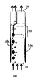
感知される同伴物質と共に気体流12を受けるための入力流路10を有するセンサデバイスが示されている。気体流は、例えば、空気流である。
A sensor device is shown having an
熱泳動構成は、入力流路の第1のより暖かい領域16から入力流路10の第2のより冷たい領域18への熱泳動粒子移動を誘発させるために使用される。図示の例では、熱泳動構成は、入力流路10の両側にヒータ14aと冷却器14bとを有している。
The thermophoretic configuration is used to induce thermophoretic particle migration from the first
この例では、入力流路の第1の領域16は、第1の出力フロー領域20に結合しており、入力流路の第2の領域は、第2の出力フロー領域22に結合している。
In this example, the
センサ24は、第1の出力フロー領域20、即ち、入力流路の第1の領域16の下流に粒子センサコンポーネントを持つ。図1は、第1の出力フロー領域20内のセンサ全体を示しているが、センサの一部は、以下の例から明らかなように遠隔であってもよい。
The
気体流中の粒子は加熱素子から離れて押し出され、センサ入力から離れる。実際には、熱勾配に依存する限られた距離でのみ熱泳動力が作用する。 Particles in the gas stream are pushed away from the heating element and away from the sensor input. In practice, the thermophoretic force acts only at a limited distance depending on the thermal gradient.
ヒータ−冷却器とセンサ入口との間の距離は、特定の実施態様では既知であり、温度変化によって変化する気体密度に影響を及ぼす。変化した密度は異なるセンサ値の表示につながるので、これはセンサ信号の処理において補正可能であり、補正される必要がある。 The distance between the heater-cooler and the sensor inlet is known in certain embodiments and affects the gas density which varies with temperature changes. Since the changed density leads to the display of different sensor values, this can be corrected in the processing of the sensor signal and needs to be corrected.
より大きな空気流入口を有するセンサの場合、センサ入口への空気流は、適切な寸法の多数の小さなサブチャネルに分割することができる。各サブチャネル内では、空気流を2つの部分に分割することができる。1つは、センサ入口の外側のチャネルを通って出てくる粒子を有する部分であり、1つは、センサに入る粒子が取り除かれた部分である。サブチャネル内では、粒子を排気チャネルに押しやるために熱泳動が使用され得る。一例が以下に与えられる。 For sensors with a larger air inlet, the air flow to the sensor inlet can be divided into a number of small sub-channels of appropriate dimensions. Within each subchannel, the air flow can be divided into two parts. One is the part with particles exiting through the channel outside the sensor inlet and the other is the part where the particles entering the sensor have been removed. Within the subchannel, thermophoresis can be used to force particles into the exhaust channel. An example is given below.
デバイスの筐体(又は、デバイス内のサブコンパートメント)への粒子の流入は、加熱されたグリッドを空気入口に配置することによって制御され得る。グリッドのメッシュサイズは、例えば、0.5mm程度であってもよい。加熱されたグリッドでの熱泳動は、気体分子を通過させながら、粒子の一部が筐体又はコンパートメントに入るのを阻止する。これは、例えば、粒子が気体センサに全く入ってこないようにすることが望ましいガスセンサの場合に望ましいことがある。 The inflow of particles into the device housing (or sub-compartment within the device) can be controlled by placing a heated grid at the air inlet. The mesh size of the grid may be about 0.5 mm, for example. Thermophoresis on a heated grid prevents some of the particles from entering the housing or compartment while allowing gas molecules to pass through. This may be desirable, for example, in the case of a gas sensor where it is desirable to prevent any particles from entering the gas sensor.
他の場合には、このようなグリッドを使用して、センサに入る粒子部分を制御することができる。例えば、グリッドの温度を下げると、粒子のより大きな部分が入ることが可能になる。メッシュサイズを大きくすると同様の結果になる。 In other cases, such a grid can be used to control the portion of particles entering the sensor. For example, lowering the temperature of the grid allows larger parts of the particles to enter. Increasing the mesh size gives similar results.
筐体に入る粒子の部分を減少させることによって、結果として得られる気体密度の変化が正確に分かっているならば、より広い範囲の粒子濃度によって特定の粒子センサの精度を維持することができる。 By reducing the portion of particles that enter the housing, the accuracy of a particular particle sensor can be maintained with a wider range of particle concentrations if the resulting change in gas density is known accurately.
代替的なアプローチでは、加熱素子をセンサの感知素子の近くに配置し、センシング表面との直接接触を避けるために、粒子を押し離すのに使用することができる。粒子を直接表面から遠くに押し出す必要はなく、直接接触しないようにするだけで十分である。 In an alternative approach, the heating element can be placed near the sensing element of the sensor and used to push the particles away to avoid direct contact with the sensing surface. It is not necessary to push the particles directly away from the surface, it is sufficient to avoid direct contact.
図2は、センサ32のセンシング表面と同じ平面にある加熱面を有するヒータ30を示している。センサは、ヒータの下流にある。加熱の効果は、センサ表面の汚染を低減するために、センサ表面から気体流を持ち上げることである。
FIG. 2 shows a
図3は、センサデバイス全体の入口41から出口42までの気体流40がある例を示す。赤外線LED44は、散乱又は反射の光学的測定に基づいて同伴粒子の光学的検出を可能にするために気体流を照射するために使用される。
FIG. 3 shows an example in which there is a
光センサ46は、フォトダイオードセンサ48と、焦点レンズ50と、を有する。(空気流の方向において)レンズ50の前に加熱素子を配置することによって、又は、レンズを直接的に加熱することによって、粒子が、レンズに直接触れることを防止することができる。
The
例えば、レンズは、サファイアなどの高い熱伝導率を有する透明な材料として形成されてもよく、その後、加熱素子(例えば、抵抗加熱素子)と直接接触してもよい。 For example, the lens may be formed as a transparent material having high thermal conductivity, such as sapphire, and may then be in direct contact with a heating element (eg, resistance heating element).
いわゆるガーネットレンズ又はキュービック結晶構造を有する他の無機材料で製造されたレンズ(これらは人工でもよいミネラルクラスである)を使用することができる。このような材料は、その大きな屈折率の観点から使用され、高い熱伝導率も有することができる。これらのレンズは、セラミックプロセスを用いて製造することができ、そのようなレンズ設計内に薄い電熱線を組み込むことが可能である。 So-called garnet lenses or lenses made of other inorganic materials with a cubic crystal structure (these are mineral classes which may be artificial) can be used. Such materials are used in view of their large refractive index and can also have high thermal conductivity. These lenses can be manufactured using a ceramic process, and it is possible to incorporate thin heating wires within such lens designs.
本発明の一実施形態によれば、光センサ46のレンズ50は、レンズカバーによって覆われている。レンズカバーは、光学的に透明であってもよく、導電性を有していてもよい。レンズカバーを加熱することにより、例えば、電圧を印加することにより、レンズの温度が上昇し、それにより、レンズ上の粒子の析出が低減又は防止される。特定の実施形態によれば、レンズカバーは、導電性である光学的透明材料から製造される。例えば、レンズカバーは、レンズカバーを通って伝播する光信号を妨げないような微細な導電性粒子を有していてもよい。レンズカバーの材料は、InO2、(In、Sn)O2、ZnO:Ga、又は、ZnO:Ga、グラフェン、又は、PEDOTなどの他の材料を有していてもよい。本発明の一実施形態によれば、レンズカバーの材料は、照明された関心のある粒子に由来する光の50%未満を吸収するように適合される。好ましくは、レンズカバーの材料は、照明された関心のある粒子に由来する光の30%未満を吸収するように適合される。より好ましくは、レンズカバーの材料は、照明された関心のある粒子に由来する光の20%未満を吸収するように適合される。
According to one embodiment of the present invention, the
このようにして、入力流路40は、第1のより暖かい領域53と、第2のより冷たい領域54と、を有する。この例におけるセンサコンポーネントは、更なる下流ではなく、入力流路のより暖かい領域53に配置されたレンズ50である。好ましくは、加熱は、入力流路がセンサコンポーネントに到達する前に少なくとも短い距離の影響を有し、その結果、熱泳動効果が機能し得る。従って、たとえこの場合であっても、ヒータがセンサコンポーネント自体に組み込まれていても、センサコンポーネントは、加熱が最初に有効である入力流路部分の下流にある。特に、ヒータから離れた温度勾配があり、それが、コンポーネント自体に到達する前に、取り込まれた同伴物質によって満たされることになる。
In this way, the
図3は、センサデバイスを通る対流を誘導するための別個のヒータ52も示している。
FIG. 3 also shows a
一般に、レンズを加熱するために多くの方法が使用され得る。上述したように、レンズ材料又はレンズカバーを直接加熱するために、抵抗ヒータが使用され得るが、代替案は、近赤外線加熱及び超音波加熱を含む。加熱方法は、もちろん、センサの動作を妨害すべきではない。 In general, many methods can be used to heat the lens. As mentioned above, resistive heaters can be used to directly heat the lens material or lens cover, but alternatives include near infrared heating and ultrasonic heating. The heating method should of course not interfere with the operation of the sensor.
加熱素子の一例は、ペルチェ加熱素子である。ペルチェ素子は、例えば、粒子の移動方向を逆転させることができるように、加熱と冷却との間で電気的に切り替えることができる。また、入力流路の両側で加熱と冷却とを簡単に実行できる。 An example of a heating element is a Peltier heating element. The Peltier element can be electrically switched between heating and cooling so that, for example, the direction of particle movement can be reversed. Further, heating and cooling can be easily performed on both sides of the input flow path.
加熱と冷却との間の制御された切り替えは、システムの動的な動作を可能にし、粒子の質量推定による更なる精度を与える。これについては以下でさらに説明する。制御された加熱ステップについても同様の議論が成立する。 Controlled switching between heating and cooling allows for dynamic operation of the system and provides further accuracy through particle mass estimation. This will be further described below. A similar argument holds for the controlled heating step.
熱泳動力は、温度勾配及び平均空気温度の逆数に比例する。所与の構成に対して、供給される熱は、粒子を動かすのに必要な力を発生させるのに十分でなければならない。増加した空気温度は、同じ効果を達成するために、より大きな温度勾配を必要とするため、適用される熱は、周囲温度に基づいて変化し得る。あるいは、予想される温度範囲又は動作温度範囲内で所望の結果を保証するように固定加熱レベルを選択することができる。加熱レベルは、例えば、加熱要素の面積及び長さに依存し、従って、予想される粒子密度及び粒子を置換するのに必要な距離に依存する。 The thermophoretic force is proportional to the temperature gradient and the inverse of the average air temperature. For a given configuration, the heat supplied must be sufficient to generate the force necessary to move the particles. Since increased air temperature requires a larger temperature gradient to achieve the same effect, the applied heat can vary based on ambient temperature. Alternatively, the fixed heating level can be selected to ensure the desired result within the expected or operating temperature range. The heating level depends, for example, on the area and length of the heating element and thus on the expected particle density and the distance required to replace the particles.
上述したように、センサ入口が大きすぎると、(現実的な温度勾配を有する)熱泳動力は、保護すべきセンサ構成要素の経路から粒子を取り除くのに十分に遠くに粒子を移動させることができない。 As mentioned above, if the sensor inlet is too large, the thermophoretic force (with a realistic temperature gradient) can move the particles far enough to remove the particles from the path of the sensor component to be protected. Can not.
図4は、3つの別々のサブチャネル60,62,64のグリッドを示している。各サブチャネルは、それ自体のヒータ66を有し、チャネル間には断熱材68がある。このようにして、入力流路は、入力サブチャネルに分割され、各サブチャネルはそれぞれの加熱構成を有し、それによって入力サブチャネルの第1及び第2の領域をそれぞれ生成する。
FIG. 4 shows a grid of three
図4は、平面図における断面図を示している。即ち、示されているサブチャネルの長さは、空気流全体の一般的な方向である。端面図、即ち、空気流によって見られる前面は、グリッド開口部の2次元又は3次元アレイを有していてもよく、それぞれがサブチャネルの1つに対応する。 FIG. 4 shows a cross-sectional view in a plan view. That is, the length of the subchannel shown is the general direction of the overall air flow. The end view, i.e. the front face seen by the air flow, may have a two-dimensional or three-dimensional array of grid openings, each corresponding to one of the subchannels.
図4において、各入力サブチャネルは、相対的に高濃度の粒子がある場合には(太い矢印70で示される)フローを生じ、粒子の濃度が比較的低い場合には(薄い矢印72で示される)フローを生じる。フロー70は、気体センサの場合にはセンサを完全にバイパスする排気口に導かれる一方、粒子センサの場合には粒子検出領域に導かれるが、汚染から保護されるセンサのコンポーネントから離れる方向に導かれる。これらのコンポーネントは、フロー72の経路にある。
In FIG. 4, each input subchannel produces a flow (indicated by a thick arrow 70) when there is a relatively high concentration of particles and a
サブチャネルの第1の領域は、一緒になって第1の出力フロー領域に結合し、サブチャネルの第2の領域は、共に第2の出力フロー領域に結合する。必要なチャネル結合配置は、図4には示されていない。 The first regions of the subchannel together couple to the first output flow region, and the second regions of the subchannel together couple to the second output flow region. The required channel coupling arrangement is not shown in FIG.
粒子は加熱された側から移動して粒子を排気流に集中させる。十分な絶縁材料68を使用してチャネルを分離し、囲まれたチャネルの両側(即ち、この例では真ん中チャネル及び右チャネル)が加熱されるのを回避する。センサが連続的に使用される場合、内部コンポーネントは時間の経過とともに熱平衡に達する。これは、消費者のソリューションには実用的なパルス式又はシーケンシャルな操作を使用することによって、あるいは、冷たい表面の能動的な冷却によって防ぐことができる。
The particles move from the heated side and concentrate the particles in the exhaust stream. Sufficient insulating
変形例は、入力流路の分離領域では幅が広いがセンサへの入口では狭い(又は、漏斗状の)単一の狭い流路を使用することである。 A variation is to use a single narrow channel that is wide in the separation region of the input channel but narrow (or funnel-shaped) at the inlet to the sensor.
図5は、粒子サイズ選択を可能にするために構成がどのように使用され得るかを示している。 FIG. 5 shows how the configuration can be used to allow particle size selection.
図5の構成では、加熱/冷却構成14a,14bの後の入力流路10の第1の領域16と、センサ24が配置された第1の出力フロー領域20との間に空間80が設けられている。この空間は、この例では、粒子の拡散を可能にするために使用される。
In the configuration of FIG. 5, a
図5(a)に示されるように、加熱構成14a,14bによって駆動される熱泳動によって全ての粒子が最初に入力流路10の一方の側で濃縮される。全ての粒子は、空気流によって一定の前進速度まで加速される。
As shown in FIG. 5 (a), all particles are first concentrated on one side of the
一旦それらが入力流路10を離れて空間80に入ると、熱泳動力はもはや作用しないが、空気流のためにそれらの速度を前方(y軸)方向に保つ。濃度勾配は、粒子を横方向(x軸)に押しやる。
Once they leave the
この拡散は、粒子サイズに依存している。 This diffusion is dependent on the particle size.
特に、粒子の拡散は、エアロゾル粒子のサイズ及び形状に依存し、小さな粒子よりも大きな粒子の拡散が遅くなる:

kは、ボルツマン定数であり、
Tは、温度であり、
CCは、カニンガムのすべり補正係数であり、
ηは、気体速度であり、
dpは、粒子の直径である。
In particular, the diffusion of particles depends on the size and shape of the aerosol particles, and the diffusion of large particles is slower than small particles:
k is the Boltzmann constant,
T is the temperature,
C C is a slip correction coefficient of Cunningham,
η is the gas velocity,
d p is the diameter of the particle.
結果として、より小さい粒子は、より大きい粒子と比較して、x軸方向においてより強い偏差を経験する。図5(a)は、象眼グラフにおけるより大きな粒子の動きを示しており、図5(b)は、象眼グラフにおけるより小さな粒子の動きを示している。 As a result, smaller particles experience a stronger deviation in the x-axis direction compared to larger particles. FIG. 5 (a) shows the movement of larger particles in the inlaid graph, and FIG. 5 (b) shows the movement of smaller particles in the inlaid graph.
空間80は、このようにしてローパスフィルタとして使用することができる。というのは、特定のサイズ以下の粒子のみがセンサに入ることができるからである。
The
このフィルタの閾値は、例えば、空間80の長さを変更することによって、又は、空気速度を制御することによって調整することができる。
This filter threshold can be adjusted, for example, by changing the length of the
図5(c)は、得られた粒子分布を示すとともに、大きな粒子がどのようにセンサから逸らされるかを示している。 FIG. 5 (c) shows the resulting particle distribution and how large particles are displaced from the sensor.
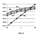
熱泳動が所望の粒子運動を生成する能力は、モデリングを用いて評価されている。この目的のために、粘土粒子が、幅10mm、高さ0.5mm(断面)、及び、長さ10mmの空気中でモデル化される。10ml/分の気体流が用いられる。 The ability of thermophoresis to produce the desired particle motion has been evaluated using modeling. For this purpose, clay particles are modeled in air having a width of 10 mm, a height of 0.5 mm (cross section) and a length of 10 mm. A gas flow of 10 ml / min is used.
熱泳動効果は、加熱側で40度、60度、及び、100度の加熱温度、並びに、反対側で21度の加熱温度でモデル化される。 The thermophoretic effect is modeled with heating temperatures of 40 degrees, 60 degrees and 100 degrees on the heating side and 21 degrees heating temperature on the opposite side.
図6は、粒子サイズ(x軸)の関数として粒子に作用する力(y軸)のプロットとしての結果を示している。プロット90は、100度の加熱用であり、プロット92は、60度の加熱用であり、プロット94は、40度の加熱用である。プロット96は、重力を示す。
FIG. 6 shows the results as a plot of the force acting on the particles (y-axis) as a function of particle size (x-axis). Plot 90 is for 100 degree heating, plot 92 is for 60 degree heating, and plot 94 is for 40 degree heating.
特定の粒子サイズでは、重力が支配的になることが分かる。温度勾配が大きければ大きいほど、熱泳動効果を用いて移動させることができる粒子サイズが大きくなる。このシミュレーションでは、3つの温度勾配について、3.0μm、4.0μm、及び、5.4μmの粒子サイズで重力が熱泳動力に打ち勝つ。 It can be seen that gravity is dominant at a particular particle size. The larger the temperature gradient, the larger the particle size that can be moved using the thermophoresis effect. In this simulation, gravity overcomes the thermophoretic force at particle sizes of 3.0 μm, 4.0 μm, and 5.4 μm for three temperature gradients.
図5及び図6は、加熱のレベル(又は、より具体的には熱勾配)が、異なるサイズ(又は、質量)の粒子にどのように影響を及ぼすかを示している。加熱のレベルは、このため、制御パラメータとして用いられることができる。粒子センサから引き出される粒子のサイズ範囲を漸進的に増加させることによって、一連のセンサ測定値を処理して粒子濃度情報を粒子サイズの関数として導出することができる。 Figures 5 and 6 show how the level of heating (or more specifically the thermal gradient) affects particles of different sizes (or mass). The level of heating can thus be used as a control parameter. By progressively increasing the size range of the particles drawn from the particle sensor, a series of sensor measurements can be processed to derive particle concentration information as a function of particle size.
この粒子サイズ(又は質量)に依存する動きは、加熱素子を制御することによって、又は、協働する加熱素子及び冷却素子を制御することによって制御され得る。ペルチェ加熱素子の場合のように、加熱素子が加熱と冷却との間で切り替え可能である場合、粒子の方向は逆転し得る。例えば、全ての粒子は、一方の側から他方の側へ漸進的に引き出されてもよく、異なる順序では、それらはすべて、他方の側から一方の側へ徐々に引き出されてもよい。これは、粒子サイズの関数としての粒子感知の精度を高めるために使用され得る他のセンサ情報を提供する。 This particle size (or mass) dependent movement can be controlled by controlling the heating element or by controlling the cooperating heating and cooling elements. If the heating element can be switched between heating and cooling, as in the case of a Peltier heating element, the direction of the particles can be reversed. For example, all particles may be drawn progressively from one side to the other, and in a different order they may all be drawn gradually from the other side to one side. This provides other sensor information that can be used to increase the accuracy of particle sensing as a function of particle size.
図7は、図5の変形例であり、空間80と組み合わされた熱泳動構成14a,14bがセンサ24のためのプレフィルタを形成する実施形態を図示している。プレフィルタは、ヒータ14aのセグメントを部分的にオン又はオフに切り替えて、空間80の長さを変えることによって、調整され得る。図7(a)では、ヒータ14a全体がスイッチオンされ、小さな粒子のみがセンサ24に到達する。図7(b)では、ヒータ14aの下部のみがオンされ、その結果、空間80が大きくなり、中程度の粒子もセンサ24に到達する。図7(c)では、ヒータ14aのセグメントはオンに切り替えられず、その結果、空間80はさらに大きくなり、大きな粒子もセンサ24に到達する。代替的なプレフィルタチューニングの例では、センサ24及び/又はヒータ14aを動かすことによって、ヒータ14a全体をセンサ24からより遠くに配置することができ、それによって空間80の長さを増加させることができる。プレフィルタは、どの粒子サイズがセンサに到達できるかをユーザが制御できるようにする。プレフィルタがブロックされないことは、本発明の利点である。これにより、粒子フィルタの寿命が延びる。
FIG. 7 is a variation of FIG. 5 and illustrates an embodiment in which the
上記の詳細な例は、全てセンサアプリケーションに関するものである。 The detailed examples above all relate to sensor applications.
ヒータ30は、表面温度を上昇させる任意の意図的な設計特徴によって実装され得る。例えば、光学部品は、システムのパッケージングの表面にあってもよい。システムがかなりの熱量を与えるコンポーネント(例えば、光源又は高出力半導体コンポーネント)を含む場合、デバイスパッケージは、発熱コンポーネントとパッケージ表面との間の熱結合を提供するように設計されてもよい。これは、発熱コンポーネント(例えば、光源)の熱安定化にも役立ち、また、熱泳動機能を実行するための加熱表面を提供する。発熱コンポーネントは、非加熱機能である主な機能(例えば、光を放出する)を有する。
The
あるいは、活性熱源、例えばジュール加熱用のワイヤグリッドが使用され得る。ペルチェ加熱素子も可能であるが、これにより、所望以上に複雑さが増す可能性がある。このアプローチは、例えばパッケージ表面でキャップを形成する光出力窓を加熱するためにTO−5パッケージで使用されてもよい。エレクトロニクスにおいて、TO−5は、トランジスタ及び幾つかの集積回路に用いられる標準化された金属半導体パッケージの名称である。TOは「トランジスタ・アウトライン」を表し、JEDECが製造した一連の技術図面を指す。能動部品の後端(パッケージ内)とキャップとの間の熱的なリンクを構築することは、光学窓をきれいに保つのに役立つ。同様の方法で、活性加熱を使用することができる。 Alternatively, an active heat source, such as a wire grid for Joule heating, can be used. Peltier heating elements are possible, but this can add more complexity than desired. This approach may be used with a TO-5 package, for example, to heat a light output window that forms a cap on the package surface. In electronics, TO-5 is the name for a standardized metal semiconductor package used for transistors and some integrated circuits. TO stands for “transistor outline” and refers to a series of technical drawings produced by JEDEC. Building a thermal link between the back end of the active component (in the package) and the cap helps keep the optical window clean. In the same way, active heating can be used.
本発明は、センサを備えた空気清浄機又は独立した空気センサに適用することができる。 The present invention can be applied to an air cleaner equipped with a sensor or an independent air sensor.
本発明の実施例では、加熱は粒子をコンポーネントから追い出すことであり、そのコンポーネントは加熱される側にある。しかしながら、これは、装置の1つの動作モードのみであってもよい。上述したように、加熱方向は交互であってもよい。この場合、デバイスは、コンポーネントが熱い側にあるモードと、コンポーネントが冷たい側にあるモードとを有することができる。従って、コンポーネントが保護される動作モードと、特定の感知機能又は感知シーケンスのための別の動作モードとがあり得る。 In an embodiment of the invention, heating is to expel particles from the component, which is on the heated side. However, this may only be one mode of operation of the device. As described above, the heating directions may be alternating. In this case, the device can have a mode in which the component is on the hot side and a mode in which the component is on the cold side. Thus, there can be an operational mode in which the component is protected and another operational mode for a particular sensing function or sensing sequence.
開示された実施形態に対する他の変更が、図面、開示、及び、添付の特許請求の範囲の研究から、クレームされた発明を実施する上で、当業者によって理解され、達成され得る。特許請求の範囲において、「有する」という単語は他の要素又はステップを排除するものではなく、単数表現は、複数の存在を除外しない。特定の手段が相互に異なる従属請求項に列挙されているという単なる事実は、これらの手段の組み合わせが有利に使用できないことを示すものではない。 Other modifications to the disclosed embodiments can be understood and attained by those skilled in the art in practicing the claimed invention, from a study of the drawings, the disclosure, and the appended claims. In the claims, the word “comprising” does not exclude other elements or steps, and the singular expression does not exclude the presence of the plural. The mere fact that certain measures are recited in mutually different dependent claims does not indicate that a combination of these measured cannot be used to advantage.
特許請求の範囲における参照符号は、その範囲を限定するものとして解釈されるべきではない。 Any reference signs in the claims should not be construed as limiting the scope.
Claims (15)
前記入力流路の第1の領域から前記入力流路の第2の領域への熱泳動粒子移動を誘発するための熱泳動構成であって、前記第1の領域は、前記第2の領域よりも暖かい前記熱泳動構成と、
前記入力流路の前記第1の領域内に、又は、前記入力流路の前記第1の領域の下流に配置される粒子センサコンポーネントを有するセンサと、
を有する、粒子センサ。 An input flow path for receiving a gas stream having an entrained substance to be sensed;
A thermophoresis configuration for inducing thermophoretic particle movement from a first area of the input flow path to a second area of the input flow path, wherein the first area is less than the second area. The warm thermophoresis configuration,
A sensor having a particle sensor component disposed within the first region of the input flow path or downstream of the first region of the input flow path;
A particle sensor.
前記入力流路の第1の領域から前記入力流路の第2の領域への熱泳動粒子移動を誘発することによって前記気体流をプレフィルタリングするステップであって、前記第1の領域は、前記第2の領域よりも暖かい前記プレフィルタリングするステップと、
前記入力流路の前記第1の領域内に、又は、前記入力流路の前記第1の領域の下流に配置される粒子センサコンポーネントを用いてセンシングを実行するステップと、
を有する、粒子センサ方法。 Receiving a flow of gas having an entrained substance to be sensed in the input flow path;
Pre-filtering the gas flow by inducing thermophoretic particle migration from a first region of the input channel to a second region of the input channel, the first region comprising: Said pre-filtering warmer than the second region;
Performing sensing using a particle sensor component disposed within the first region of the input flow path or downstream of the first region of the input flow path; and
A particle sensor method comprising:
Applications Claiming Priority (5)
| Application Number | Priority Date | Filing Date | Title |
|---|---|---|---|
| CN2015075276 | 2015-03-27 | ||
| CNPCT/CN2015/075276 | 2015-03-27 | ||
| EP15166494 | 2015-05-06 | ||
| EP15166494.3 | 2015-05-06 | ||
| PCT/EP2016/055615 WO2016156035A1 (en) | 2015-03-27 | 2016-03-16 | Protecting an optical particle sensor from particulate deposits by thermophoresis |
Publications (2)
| Publication Number | Publication Date |
|---|---|
| JP2018512563A true JP2018512563A (en) | 2018-05-17 |
| JP2018512563A5 JP2018512563A5 (en) | 2019-11-14 |
Family
ID=55650387
Family Applications (1)
| Application Number | Title | Priority Date | Filing Date |
|---|---|---|---|
| JP2017538640A Pending JP2018512563A (en) | 2015-03-27 | 2016-03-16 | Sensor device and method |
Country Status (5)
| Country | Link |
|---|---|
| US (1) | US10363514B2 (en) |
| EP (1) | EP3274071B1 (en) |
| JP (1) | JP2018512563A (en) |
| CN (1) | CN107532996B (en) |
| WO (1) | WO2016156035A1 (en) |
Families Citing this family (14)
| Publication number | Priority date | Publication date | Assignee | Title |
|---|---|---|---|---|
| CN107478576B (en) * | 2016-06-07 | 2024-02-20 | 宁波方太厨具有限公司 | Protective structure of oil smoke sensor |
| US10215699B2 (en) * | 2017-01-03 | 2019-02-26 | Honeywell International Inc. | Utilizing updraft flow in a fan-less dust sensor |
| EP3444587A1 (en) * | 2017-08-14 | 2019-02-20 | Koninklijke Philips N.V. | Particle sensor and particle sensing method |
| EP3642587B1 (en) | 2017-06-21 | 2020-12-30 | Koninklijke Philips N.V. | Particle sensor and particle sensing method |
| GB201715014D0 (en) | 2017-09-18 | 2017-11-01 | Cambridge Entpr Ltd | Particulate matter detection |
| US11326991B2 (en) * | 2017-11-14 | 2022-05-10 | Aerodyne Microsystems Inc. | Airborne particle detection with selective thermophoretic particle deflection |
| DE102018219891A1 (en) * | 2018-11-20 | 2020-05-20 | Robert Bosch Gmbh | Method for operating a particle sensor |
| US11828210B2 (en) | 2020-08-20 | 2023-11-28 | Denso International America, Inc. | Diagnostic systems and methods of vehicles using olfaction |
| US11636870B2 (en) | 2020-08-20 | 2023-04-25 | Denso International America, Inc. | Smoking cessation systems and methods |
| US11760169B2 (en) | 2020-08-20 | 2023-09-19 | Denso International America, Inc. | Particulate control systems and methods for olfaction sensors |
| US11813926B2 (en) | 2020-08-20 | 2023-11-14 | Denso International America, Inc. | Binding agent and olfaction sensor |
| US11932080B2 (en) | 2020-08-20 | 2024-03-19 | Denso International America, Inc. | Diagnostic and recirculation control systems and methods |
| US11760170B2 (en) | 2020-08-20 | 2023-09-19 | Denso International America, Inc. | Olfaction sensor preservation systems and methods |
| US11881093B2 (en) | 2020-08-20 | 2024-01-23 | Denso International America, Inc. | Systems and methods for identifying smoking in vehicles |
Citations (16)
| Publication number | Priority date | Publication date | Assignee | Title |
|---|---|---|---|---|
| JPS57131036A (en) * | 1981-02-06 | 1982-08-13 | Rion Co Ltd | Light scattering type floating particle counting |
| JPH01305341A (en) * | 1988-04-11 | 1989-12-08 | Westinghouse Electric Corp <We> | Method and apparatus for obtaining reading of non-transparency monitor periodically |
| JPH0527654U (en) * | 1991-09-19 | 1993-04-09 | 神栄株式会社 | Air pollution detector |
| JPH0676333A (en) * | 1992-08-25 | 1994-03-18 | Mitsubishi Electric Corp | Dust guard for objective lens of optical disk |
| JPH06120149A (en) * | 1990-05-11 | 1994-04-28 | Applied Materials Inc | System and method for monitoring of particles |
| JPH06241974A (en) * | 1993-02-22 | 1994-09-02 | Shimadzu Corp | Grain size distribution measuring device |
| JPH0755687A (en) * | 1993-07-08 | 1995-03-03 | Applied Materials Inc | Particulate monitor sensor |
| GB2319191A (en) * | 1996-11-15 | 1998-05-20 | Boris Gorbunov | A particulate matter concentrator |
| US20060066834A1 (en) * | 2004-09-28 | 2006-03-30 | Phillips Alton H | EUV reticle handling system and method |
| JP2008175590A (en) * | 2007-01-16 | 2008-07-31 | Tokyo Electron Ltd | Particle monitor system and substrate processing device |
| US20090019918A1 (en) * | 2007-03-28 | 2009-01-22 | Robert Bosch Gmbh | Procedure for operating a collecting particle sensor and device for implementing this procedure |
| DE102008041809A1 (en) * | 2008-09-04 | 2010-03-11 | Robert Bosch Gmbh | Particle sensor, particularly resistive particle sensor for detection of conductive particles in gas stream, comprises two electrode systems with primary electrode and secondary electrode, and ceramic base body |
| JP2011256796A (en) * | 2010-06-09 | 2011-12-22 | Toyota Motor Corp | Pm quantity detection system |
| JP2012154620A (en) * | 2004-08-11 | 2012-08-16 | Koninkl Philips Electronics Nv | Air pollution sensor system |
| JP2012220263A (en) * | 2011-04-05 | 2012-11-12 | Shimadzu Corp | Particle size measuring device |
| US20130133441A1 (en) * | 2011-05-24 | 2013-05-30 | Rj Lee Group | Thermophoretic sampler |
Family Cites Families (15)
| Publication number | Priority date | Publication date | Assignee | Title |
|---|---|---|---|---|
| US4675031A (en) * | 1985-08-19 | 1987-06-23 | Sinnar Abbas M | Phoretic enhanced-gravity particulate removal system |
| GB8818463D0 (en) * | 1988-08-03 | 1988-09-07 | Loughborough Consult Ltd | Apparatus & method for removing particulate matter from exhaust gases of i c engine |
| GB2339398B (en) * | 1998-07-10 | 2002-05-01 | Notetry Ltd | Apparatus and method for concentrating gasborne particles in a portion of a gas stream |
| US20020159215A1 (en) | 1999-12-06 | 2002-10-31 | Siess Harold Edward | Protecting transmissive surfaces |
| US8177142B2 (en) | 2005-08-26 | 2012-05-15 | Ricciardi Jonathan J | Method and apparatus for an improved aerosol generator and associated uses and equipment |
| EP2255178A1 (en) * | 2008-02-27 | 2010-12-01 | Volvo Technology Corporation | Method and arrangement for detecting particles |
| DE102009000820A1 (en) | 2009-02-12 | 2010-08-19 | Robert Bosch Gmbh | Sensor element of a gas sensor and method for operating the same |
| WO2011135717A1 (en) * | 2010-04-30 | 2011-11-03 | トヨタ自動車株式会社 | Particulate matter quantity detection apparatus |
| US8806915B2 (en) * | 2011-08-08 | 2014-08-19 | University Of California | Microfabricated particulate matter monitor |
| US20130235357A1 (en) | 2012-03-12 | 2013-09-12 | Kla-Tencor Corporation | System and Method for Particle Control Near A Reticle |
| CN102692368A (en) * | 2012-05-23 | 2012-09-26 | 华北电力大学 | Visual narrow rectangular channel aerosol motion deposition system |
| KR20130134243A (en) * | 2012-05-30 | 2013-12-10 | 연세대학교 산학협력단 | Particle sampling cell and laser measurement system contains the same |
| US9389180B2 (en) * | 2013-02-15 | 2016-07-12 | Kla-Tencor Corporation | Methods and apparatus for use with extreme ultraviolet light having contamination protection |
| CN103349879B (en) * | 2013-07-04 | 2015-05-20 | 清华大学 | Thermophoretic air purifying device and method |
| GB201715014D0 (en) * | 2017-09-18 | 2017-11-01 | Cambridge Entpr Ltd | Particulate matter detection |
-
2016
- 2016-03-16 CN CN201680018709.1A patent/CN107532996B/en active Active
- 2016-03-16 JP JP2017538640A patent/JP2018512563A/en active Pending
- 2016-03-16 EP EP16713753.8A patent/EP3274071B1/en active Active
- 2016-03-16 US US15/557,492 patent/US10363514B2/en active Active
- 2016-03-16 WO PCT/EP2016/055615 patent/WO2016156035A1/en active Application Filing
Patent Citations (16)
| Publication number | Priority date | Publication date | Assignee | Title |
|---|---|---|---|---|
| JPS57131036A (en) * | 1981-02-06 | 1982-08-13 | Rion Co Ltd | Light scattering type floating particle counting |
| JPH01305341A (en) * | 1988-04-11 | 1989-12-08 | Westinghouse Electric Corp <We> | Method and apparatus for obtaining reading of non-transparency monitor periodically |
| JPH06120149A (en) * | 1990-05-11 | 1994-04-28 | Applied Materials Inc | System and method for monitoring of particles |
| JPH0527654U (en) * | 1991-09-19 | 1993-04-09 | 神栄株式会社 | Air pollution detector |
| JPH0676333A (en) * | 1992-08-25 | 1994-03-18 | Mitsubishi Electric Corp | Dust guard for objective lens of optical disk |
| JPH06241974A (en) * | 1993-02-22 | 1994-09-02 | Shimadzu Corp | Grain size distribution measuring device |
| JPH0755687A (en) * | 1993-07-08 | 1995-03-03 | Applied Materials Inc | Particulate monitor sensor |
| GB2319191A (en) * | 1996-11-15 | 1998-05-20 | Boris Gorbunov | A particulate matter concentrator |
| JP2012154620A (en) * | 2004-08-11 | 2012-08-16 | Koninkl Philips Electronics Nv | Air pollution sensor system |
| US20060066834A1 (en) * | 2004-09-28 | 2006-03-30 | Phillips Alton H | EUV reticle handling system and method |
| JP2008175590A (en) * | 2007-01-16 | 2008-07-31 | Tokyo Electron Ltd | Particle monitor system and substrate processing device |
| US20090019918A1 (en) * | 2007-03-28 | 2009-01-22 | Robert Bosch Gmbh | Procedure for operating a collecting particle sensor and device for implementing this procedure |
| DE102008041809A1 (en) * | 2008-09-04 | 2010-03-11 | Robert Bosch Gmbh | Particle sensor, particularly resistive particle sensor for detection of conductive particles in gas stream, comprises two electrode systems with primary electrode and secondary electrode, and ceramic base body |
| JP2011256796A (en) * | 2010-06-09 | 2011-12-22 | Toyota Motor Corp | Pm quantity detection system |
| JP2012220263A (en) * | 2011-04-05 | 2012-11-12 | Shimadzu Corp | Particle size measuring device |
| US20130133441A1 (en) * | 2011-05-24 | 2013-05-30 | Rj Lee Group | Thermophoretic sampler |
Also Published As
| Publication number | Publication date |
|---|---|
| EP3274071A1 (en) | 2018-01-31 |
| CN107532996A (en) | 2018-01-02 |
| US10363514B2 (en) | 2019-07-30 |
| CN107532996B (en) | 2020-09-01 |
| EP3274071B1 (en) | 2023-05-24 |
| WO2016156035A1 (en) | 2016-10-06 |
| US20180056228A1 (en) | 2018-03-01 |
Similar Documents
| Publication | Publication Date | Title |
|---|---|---|
| JP2018512563A (en) | Sensor device and method | |
| CN110785645B (en) | Particle sensor and particle sensing method | |
| JP4369965B2 (en) | Aerosol measurement system and method | |
| EP2279402B1 (en) | A condensation apparatus | |
| JP2018512563A5 (en) | ||
| CN106461527A (en) | Aerosol sensor and sensing method | |
| US8272279B2 (en) | Systems and methods for chemical sampling in particulate laden gaseous environments | |
| KR200484692Y1 (en) | Apparatus and process for producing acknowledged air flow and the use of such apparatus in measuring particle concentration in acknowledged air flow | |
| Shou et al. | Filtration efficiency of non-uniform fibrous filters | |
| Tauber et al. | Counting efficiency determination from quantitative intercomparison between expansion and laminar flow type condensation particle counter | |
| JP7127247B2 (en) | Particle sensors and methods for measuring particle concentrations | |
| WO2020074732A1 (en) | Condensation particle counter | |
| JP5852834B2 (en) | Evaluation system for particle detector and evaluation method for particle detector | |
| CN104697821A (en) | Air detection device, air sampling device and air sampling method | |
| Sun et al. | A miniature system for particulate matter (PM) measurement | |
| Leung et al. | Gold nano-particle-based thermal sensors fabricated using microspotting and DEP techniques | |
| EP3444587A1 (en) | Particle sensor and particle sensing method | |
| Surib et al. | Shinyei based sensor with added roof enhanced detection of indoor particulate matter | |
| Kim et al. | The spatial resolution of dual-tracer fluorescence thermometry in volumetrically illuminated channels | |
| Romay et al. | Water-based single-flow mixing condensation particle counter | |
| Okuwaki et al. | Plastic Based Microfluidic Chip for Optical Diffusion Sensor Using Laser-Induced Dielectrophoresis | |
| Clement | Washing the air: enhanced condensation of water on aerosols to enable their removal | |
| RU145468U1 (en) | SENSITIVE ELEMENT OF A FLUID OR GAS FLOW SENSOR | |
| Mithran et al. | Shape and Size Effects of Glass Mini-Channels on Infrared Sensors in Air–Water Two-Phase Flow | |
| Huskey | Interferometric Measurement of the Index of Refraction of Liquids |
Legal Events
| Date | Code | Title | Description |
|---|---|---|---|
| A521 | Request for written amendment filed |
Free format text: JAPANESE INTERMEDIATE CODE: A523 Effective date: 20190110 |
|
| A621 | Written request for application examination |
Free format text: JAPANESE INTERMEDIATE CODE: A621 Effective date: 20190110 |
|
| RD02 | Notification of acceptance of power of attorney |
Free format text: JAPANESE INTERMEDIATE CODE: A7422 Effective date: 20190308 |
|
| A521 | Request for written amendment filed |
Free format text: JAPANESE INTERMEDIATE CODE: A523 Effective date: 20191001 |
|
| A871 | Explanation of circumstances concerning accelerated examination |
Free format text: JAPANESE INTERMEDIATE CODE: A871 Effective date: 20191001 |
|
| A977 | Report on retrieval |
Free format text: JAPANESE INTERMEDIATE CODE: A971007 Effective date: 20190930 |
|
| A975 | Report on accelerated examination |
Free format text: JAPANESE INTERMEDIATE CODE: A971005 Effective date: 20191010 |
|
| A131 | Notification of reasons for refusal |
Free format text: JAPANESE INTERMEDIATE CODE: A131 Effective date: 20191018 |
|
| A521 | Request for written amendment filed |
Free format text: JAPANESE INTERMEDIATE CODE: A523 Effective date: 20191219 |
|
| A131 | Notification of reasons for refusal |
Free format text: JAPANESE INTERMEDIATE CODE: A131 Effective date: 20200303 |
|
| A02 | Decision of refusal |
Free format text: JAPANESE INTERMEDIATE CODE: A02 Effective date: 20201006 |