EP3273341A1 - Electronic device and information update method - Google Patents
Electronic device and information update method Download PDFInfo
- Publication number
- EP3273341A1 EP3273341A1 EP17176959.9A EP17176959A EP3273341A1 EP 3273341 A1 EP3273341 A1 EP 3273341A1 EP 17176959 A EP17176959 A EP 17176959A EP 3273341 A1 EP3273341 A1 EP 3273341A1
- Authority
- EP
- European Patent Office
- Prior art keywords
- information
- setup
- control unit
- wireless tag
- communication
- Prior art date
- Legal status (The legal status is an assumption and is not a legal conclusion. Google has not performed a legal analysis and makes no representation as to the accuracy of the status listed.)
- Granted
Links
Images




Classifications
-
- G—PHYSICS
- G06—COMPUTING OR CALCULATING; COUNTING
- G06F—ELECTRIC DIGITAL DATA PROCESSING
- G06F3/00—Input arrangements for transferring data to be processed into a form capable of being handled by the computer; Output arrangements for transferring data from processing unit to output unit, e.g. interface arrangements
- G06F3/12—Digital output to print unit, e.g. line printer, chain printer
- G06F3/1201—Dedicated interfaces to print systems
- G06F3/1278—Dedicated interfaces to print systems specifically adapted to adopt a particular infrastructure
- G06F3/1292—Mobile client, e.g. wireless printing
-
- G—PHYSICS
- G06—COMPUTING OR CALCULATING; COUNTING
- G06F—ELECTRIC DIGITAL DATA PROCESSING
- G06F3/00—Input arrangements for transferring data to be processed into a form capable of being handled by the computer; Output arrangements for transferring data from processing unit to output unit, e.g. interface arrangements
- G06F3/12—Digital output to print unit, e.g. line printer, chain printer
- G06F3/1201—Dedicated interfaces to print systems
- G06F3/1202—Dedicated interfaces to print systems specifically adapted to achieve a particular effect
- G06F3/1203—Improving or facilitating administration, e.g. print management
- G06F3/1204—Improving or facilitating administration, e.g. print management resulting in reduced user or operator actions, e.g. presetting, automatic actions, using hardware token storing data
-
- G—PHYSICS
- G06—COMPUTING OR CALCULATING; COUNTING
- G06F—ELECTRIC DIGITAL DATA PROCESSING
- G06F3/00—Input arrangements for transferring data to be processed into a form capable of being handled by the computer; Output arrangements for transferring data from processing unit to output unit, e.g. interface arrangements
- G06F3/12—Digital output to print unit, e.g. line printer, chain printer
- G06F3/1201—Dedicated interfaces to print systems
- G06F3/1223—Dedicated interfaces to print systems specifically adapted to use a particular technique
- G06F3/1236—Connection management
-
- G—PHYSICS
- G06—COMPUTING OR CALCULATING; COUNTING
- G06F—ELECTRIC DIGITAL DATA PROCESSING
- G06F3/00—Input arrangements for transferring data to be processed into a form capable of being handled by the computer; Output arrangements for transferring data from processing unit to output unit, e.g. interface arrangements
- G06F3/12—Digital output to print unit, e.g. line printer, chain printer
- G06F3/1296—Printer job scheduling or printer resource handling
-
- H—ELECTRICITY
- H04—ELECTRIC COMMUNICATION TECHNIQUE
- H04B—TRANSMISSION
- H04B5/00—Near-field transmission systems, e.g. inductive or capacitive transmission systems
- H04B5/20—Near-field transmission systems, e.g. inductive or capacitive transmission systems characterised by the transmission technique; characterised by the transmission medium
-
- H—ELECTRICITY
- H04—ELECTRIC COMMUNICATION TECHNIQUE
- H04L—TRANSMISSION OF DIGITAL INFORMATION, e.g. TELEGRAPHIC COMMUNICATION
- H04L67/00—Network arrangements or protocols for supporting network services or applications
- H04L67/34—Network arrangements or protocols for supporting network services or applications involving the movement of software or configuration parameters
-
- H—ELECTRICITY
- H04—ELECTRIC COMMUNICATION TECHNIQUE
- H04W—WIRELESS COMMUNICATION NETWORKS
- H04W4/00—Services specially adapted for wireless communication networks; Facilities therefor
- H04W4/80—Services using short range communication, e.g. near-field communication [NFC], radio-frequency identification [RFID] or low energy communication
-
- G—PHYSICS
- G06—COMPUTING OR CALCULATING; COUNTING
- G06F—ELECTRIC DIGITAL DATA PROCESSING
- G06F3/00—Input arrangements for transferring data to be processed into a form capable of being handled by the computer; Output arrangements for transferring data from processing unit to output unit, e.g. interface arrangements
- G06F3/12—Digital output to print unit, e.g. line printer, chain printer
- G06F3/1201—Dedicated interfaces to print systems
- G06F3/1223—Dedicated interfaces to print systems specifically adapted to use a particular technique
- G06F3/1237—Print job management
-
- G—PHYSICS
- G06—COMPUTING OR CALCULATING; COUNTING
- G06F—ELECTRIC DIGITAL DATA PROCESSING
- G06F3/00—Input arrangements for transferring data to be processed into a form capable of being handled by the computer; Output arrangements for transferring data from processing unit to output unit, e.g. interface arrangements
- G06F3/12—Digital output to print unit, e.g. line printer, chain printer
- G06F3/1201—Dedicated interfaces to print systems
- G06F3/1278—Dedicated interfaces to print systems specifically adapted to adopt a particular infrastructure
- G06F3/1285—Remote printer device, e.g. being remote from client or server
Definitions
- the present disclosure relates to an electronic device and information update method that are suitable for writing information to a wireless tag such as a NFC (Near Field Communications) tag.
- a wireless tag such as a NFC (Near Field Communications) tag.
- a wireless tag may be mouned in an image-forming apparatus that is a MFP (Multifunctional Peripheral) such as a printer, multifunction printer, combination machine and the like.
- a wireless tag is a NFC tag or the like that stores wired or wireless connection information necessary for connecting to a network, machine information such as a machine name, and the like.
- the connection information and the machine information of the wireless tag is rewritten by the image-forming apparatus.
- the image-forming apparatus automatically updates the connection information of the wireless tag as the connection information is updated.
- a wireless tag reader/writer function that is installed in a portable terminal to read the connection information and the machine information of the wireless tag or to write user-specific information to a wireless tag for activating various kinds of application programs that are installed, for example, in the portable terminal.
- a printer on which an IC (Integrated Circuit) tag is mounted that stores information related to an output destination or the like.
- a portable terminal having an IC card reader reads the information on the IC tag that is related to the output destination, and notifies a client PC (Personal Computer) about the information related to the output destination, printing settings and the like.
- client PC Personal Computer
- There is a printing system that performs a printing process by having the client PC transmit spooled job information to a printer at the output destination.
- the electronic device includes a first communication-control unit and a first system-control unit.
- the first communication-control unit controls communication with a wireless tag that is capable of storing setup information that has status information indicating a setup state.
- the first system-control unit checks via the first communication-control unit whether or not the setup information is stored in the wireless tag, and when the setup information is stored, reads the setup information.
- the first system-control unit executes setup based on the setup information, and rewrites the status information to correspond to the setup state.
- the electronic device includes a second communication-control unit and a second system-control unit.
- the second communication-control unit controls communication with a wireless tag.
- the second system-control unit via the second communication-control unit, reads management information that manages the data write area of the wireless tag.
- the second system-control unit writes setup information that has status information indicating the setup state in the empty area.
- the information update method is an information update method that causes a computer that controls an electronic device to execute:a step for controlling communication with a wireless tag that is capable of storing setup information having status information that indicates a setup state; a step for checking whether or not the setup information is stored in the wireless tag, and when the setup information is stored, reading the setup information; and a step for executing setup based on the setup information, and rewriting the status information to correspond to the setup state.
- the information update method is an information update method that causes a computer that controls an electronic device to execute:a step of controlling communication with a wireless tag; a step of reading management information for managing a data write area of the wireless tag; and when there is an empty area in the management information, a step of writing setup information having status information that indicates a setup state in the empty area.
- an embodiment of an electronic device of the present disclosure will be explained with reference to FIG. 1 to FIG. 6 .
- an electronic device there is an MFP (Multifunctional Peripheral) that is a complex peripheral device equipped, for example, with a printing function, a copying function, a FAX function, a data transmission/reception function via a network, and the like, or a portable terminal such as a smartphone and the like.
- MFP Multifunctional Peripheral
- the portable terminal it is also possible to use a tablet terminal, laptop computer and the like.
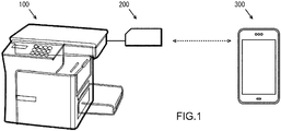
- an NFC (Near Field Communications) tag (hereafter, referred to as a wireless tag) 200 is connected to an MFP 100.
- the wireless tag 200 is connected to the MFP 100 by a wired connection (a serial bus such as a 12C bus and the like).
- the wireless tag 200 is wirelessly connected to a portable terminal 300.
- information that is stored in the wireless tag 200 can be rewritten by the MFP 100 and the portable terminal 300.
- user-specific information or setup information for activating various application programs that are installed in the portable terminal 300 can be written in the wireless tag 200 by the portable terminal 300.
- the MFP 100 includes a control unit 110 that controls a printer unit 101, an I/F (interface) 102, a panel unit 103, and an HDD 104.
- the MFP 100 may also include a scanner unit, a FAX unit and the like.
- the printer unit 101 is a device that prints images on paper based on printing data that is outputted from the control unit 110.
- the I/F 102 is in charge of communication with the wireless tag 200.
- the I/F 102 is in charge of communication with the portable terminal 300 via a network such as a LAN (Local Area Network).
- the I/F 102 may also be in charge of communication with a content server, a webserver and the like.
- the panel unit 103 is a device such as a touch panel for performing a display for the printing function, the copying function, the FAX function, the data transmission/reception function via a network, and for various settings of the MFP 100.
- the HDD 104 is a storage device for storing application programs and the like for providing the various functions of the MFP 100. Furthermore, the HDD 104 has, for example, user boxes that store printing jobs that are registered from user terminals.
- the control unit 110 is a processor that controls the overall operation of the MFP 100 by executing an image-forming program, control program and the like.
- the control unit 110 includes a printer-control unit 111, a communication-control unit 112, a RAM 113, a ROM 114, an image-processing unit 115, a panel-operation-control unit 116, an HDD-control unit 117 and a system-control unit 118. Moreover, these are connected to a database 119.
- the printer-control unit 111 controls the printing operation of the printer unit 101.
- the communication-control unit 112 controls transmission/reception with the wireless tag 200 and the like via the I/F 102.
- the RAM 113 is a work memory for executing programs. A control program for checking the operation of each unit and the like is stored in the ROM 114.
- the image-processing unit 115 performs image processing (rasterization) on a printing job that is registered in a user box of the HDD 104, for example.
- the system-control unit 118 causes printing data that has undergone image processing by the image-processing unit 115 to be stored temporarily in the RAM 113.
- the panel-operation-control unit 116 controls the display operation of the panel unit 103. Moreover, the panel-operation-control unit 116, via the panel unit 103, receives start settings and the like for printing, copying, FAX, data transmission/reception via a network and the like.
- the HDD-control unit 117 controls reading data from and writing data to the HDD 104.
- the system-control unit 118 controls the cooperative operation of each unit. Although described in detail later, the system-control unit 118 reads, for example, setup information or the like that is written in the wireless tag 200, and executes setup and the like.
- the wireless tag 200 includes a control unit 210 that controls the I/F 201.
- the I/F 201 is in charge of communication with the MFP 100.
- the control unit 210 has an antenna unit 211 and an IC chip 212.
- the antenna unit 211 performs communication with the portable terminal 300 using a specific frequency (for example, 13.56 MHz).
- the IC chip 212 has a non-volatile memory that stores NFC user data and the like that will be described later.
- the IC chip 212 writes information received via the I/F 201 or antenna unit 211 to the non-volatile memory, and transmits information in the non-volatile memory via the I/F 201 or antenna unit 211.
- the information in the non-volatile memory is written in a format that is defined according to the NFC standard.
- the portable terminal 300 includes a control unit 310 that controls an antenna 301 and a panel unit 302.
- the antenna 301 is in charge of communication with the wireless tag 200 and the like.
- the antenna 301 is in charge of communication with the MFP 100, a content server, a web server and the like via a network.
- the panel unit 302 is a device such as a touch panel for selecting the various functions of the portable terminal 300, inputting text, displaying information and the like.
- the control unit 310 is a processor that controls the overall operation of the portable terminal 300 by executing application programs and control programs.
- the control unit 310 includes a communication-control unit 311, a RAM 312, a ROM 313, a panel-operation-control unit 314 and a system-control unit 315. Moreover, these units are connected to a data bus 316.
- the communication-control unit 311 performs control of transmission and reception with the wireless tag 200, MFP 100 and the like via the antenna 301.
- the RAM 312 is a work memory for executing programs.
- a control program for checking the operation of each unit and the like is stored in the ROM 313.
- the panel-operation-control unit 314 controls the display operation and the like of the panel unit 302.
- the system-control unit 315 controls the cooperative operation and the like of each unit. Moreover, the system-control unit 315 has a wireless tag reader/writer function, and when there is an instruction via the panel unit 302 to read or write the information of the wireless tag 200, the system-control unit 315 transmits a radio wave to the communication-control unit 311 from the antenna 301.
- the wireless tag 200 has, for example, NFC information (1) that has an area 221 where NFC user data is written and an empty area 222, and NFC information (2) that has a system area 223.
- the NFC information (1) and the NFC information (2) are management information for managing areas where data is written and the like.
- NFC information (1) has, for example, the size of area 201 where NFC user data is written, and the size of the empty area 222.
- the NFC information (2) has, for example, the size of the system area 223.
- Device information of the MFP 100 is written in the area 221 where the NFC user data is written.
- the machine name, wired and wireless connection information for a network, and the like are written, for example, as device information.
- setup information (1), setup information (2) and the like can be written in the empty area 222 of the NFC information (1).
- the setup information (1) and setup information (2) each have different information contents related to setup.
- FIG. 3A to FIG. 3D are enlarged views of the empty area 222, and illustrate the state of the setup information (1) and the setup information (2) being written in the empty area 222. In this state, the empty area is an area that excludes the area where the setup information (1) and setup information (2) are stored.
- the setup information (1) has, for example, a header and data.
- the header includes, for example, start of tag information, data size, setup type, post-setup processing, and status information.
- the data includes setup data.
- the start of tag information indicates that starting position of the setup data.
- the data size indicates the effective size of the setup information.
- the setup type indicates what kind of setup is to be performed. Post-setup processing indicates how setup data will be handled after setup is complete (for example, deletion, storage in the HDD 104 or the like).
- the status information indicates whether setup is incomplete, complete or failed.
- the setup data indicates information required for setup. For example, the ID number and serial number of the mounted unit, adjustment information, connection information with an external server, and the like are written in the setup information (1). More specifically, the setup type, indicates, for example, performing settings of the mounted unit that corresponds to the ID number and serial number in the setup data to a default value based on adjustment information and the like, or performing connection settings based on connection information.
- reference number 410 indicates a reading device
- reference number 420 indicates a lower cassette
- reference number 430 indicates a database server
- reference number 440 indicates a network such as the Internet.
- the reading device 410 and the lower cassette 420 are prepared as options of the MFP 100.
- Options of the MFP 100 besides the reading device 410 and lower cassette 420, such as a finisher that is capable of sorting and stapling when printing plural copies may also be prepared, however, an explanation of other options will be omitted here.
- An external terminal constructs information 411 and 421 related to the assembly process of the reading device 410 and lower cassette 420.
- a unit serial number, adjustment setting values, firmware version and the like of the reading unit 410, for example, are included in the information 411.
- a unit serial number, adjustment setting values, firmware version and the like of the lower cassette 420, for example, are included in the information 421.
- barcodes 412 and 422 that indicate the respective unit serial numbers are prepared. These barcodes are adhered to the side surfaces of the reading device 410 and the lower cassette 420. Furthermore, these barcodes may be printed in or affixed to the instruction manuals of the reading device 410 and lower cassette 420.
- An external terminal via a network 440, registers the information 411, 421 related to the assembly processes of reading device 410 and lower cassette 420 in the database server 430.
- the portable terminal 300 reads each of the barcodes 412, 422, and obtains the respective unit serial numbers.
- the portable terminal 300 accesses the database server 430 based on the obtained unit serial numbers, and obtains the information 411, 421 related to the assembly processes of the reading device 410 and lower cassette 420.
- the portable terminal 300 writes the obtained information 411, 421 related to the assembly processes of the reading device 410 and lower cassette 420 to the wireless tag 200.
- the portable terminal 300 writes the information 411 related to the assembly process of the reading device 410 as the setup information (1) in FIG. 3B , for example.
- the portable terminal 300 writes the information 421 related to the assembly process of the lower cassette 420 as the setup information (2) in FIG. 3B , for example.
- the MFP 100 reads, for example, the setup information (1), (2) in FIG. 3B , and executes setup.
- the timing at which the MFP 100 reads the setup information (1), (2) may be when the power to the MFP 100 is turned ON, or may be when a read instruction from reading the setup information (1), (2) is given from the panel unit 103 or the portable terminal 300.
- step S105 the portable terminal 300 may write the respective unit serial numbers to the wireless tag 200, and in step S106, the MFP 100 may access the database server 430 and obtain the information 411, 412 related to the assembly processes of the reading device 410 and lower cassette 420.
- the system-control unit 315 reads the wireless tag 200.
- the system-control unit 315 via the communication-control unit 311, reads the wireless tag 200 by near field communication with the wireless tag 200.
- the system-control unit 315 determines whether or not there is an empty area 222 in the wireless tag 200.
- the system-control unit 315 by using near field communication with the wireless tag 200, reads the size of the empty area 222 of the NFC information (1) illustrated in FIG. 3 , for example, and when the system-control unit 315 determines that there is an empty area 222 (step S202: YES), proceeds to step S206.
- step S202 determines that there is no empty area 222 (step S202: NO)
- the system-control unit proceeds to step S203.
- the system-control unit 315 reads the status information of the wireless tag 200.
- the system-control unit 315 uses near field communication with the wireless tag 200 to read status information that is written in the header of the setup information (1) that is illustrated in FIG. 3 for example.
- the system-control unit 315 determines whether or not the status is "setup incomplete".
- step S204 determines that the status is not "setup incomplete” (step S204: NO), and proceeds to step S206.
- step S204 determines that the status is "setup incomplete" (step S204: YES), and proceeds to step S205.
- the system-control unit 315 displays that there is no empty area 222.
- the system-control unit 315 via the panel-operation-control unit 314, causes the panel unit 302 to display that there is no empty area 222.
- the system-control unit 315 cancels the writing password.
- the system-control unit 315 transmits a password that is inputted via the panel unit 302 to the wireless tag 200.
- the system-control unit 315 determines whether or not cancellation is successful.
- the system-control unit 315 by using near field communication with the wireless tag 200, determines that cancellation is successful when the password is cancelled (step S207: YES), and proceeds to step S209.
- step S207 determines that cancellation is not successful when the password is not cancelled (step S207: NO), and proceeds to step S208.
- the system-control unit 315 displays that authentication is failed.
- the system-control unit 315 via the panel-operation-control unit 314, causes the panel unit 302 to display that authentication is failed.
- the system-control unit 315 writes setup information.
- the system-control unit 315 by using near field communication with the wireless tag 200, writes setup information (1) for example in the empty area 222 of the wireless tag 200. Moreover, when there is no empty space in the wireless tag 200, the system-control unit 315, by using near field communication with the wireless tag 200, may delete setup information that is already written in the wireless tag 200, and then write the setup information (1).
- the contents of the setup information (1) may be, for example, the information 411, 421 related to the assembly processes of the reading device 410 and lower cassette 420 that were explained using FIG. 4 . Moreover, the status information of the setup information (1) is "incomplete".
- the information that is to be written in the empty area 222 of the wireless tag 200 is not particularly limited. For example, user-specific information or the like for activating various application programs that are stored in the portable terminal 300 may be written.
- the system-control unit 315 determines whether or not writing is successful.
- step S210 when the system-control unit 315, by using near field communication with the wireless tag 200, determines that writing is successful (step S210: YES), the system-control unit 315 proceeds to step S212.
- step S210 determines that writing is not successful (step S210: NO)
- the system-control unit 315 proceeds to step S211.
- the system-control unit 315 displays that writing is failed.
- the system-control unit 315 via the panel-operation-control unit 314, causes the panel unit 302 to display that writing is failed.
- the system-control unit 315 displays that writing is complete.
- the system-control unit 315 via the panel-operation-control unit 314, causes the panel unit 302 to display that writing is complete.
- processing on the MFP 100 side will be explained with reference to FIG. 6 .
- the processing described below is executed, for example when the power to the MFP 100 is turned ON.
- the system-control unit 118 read the wireless tag 200.
- the system-control unit 118 via the communication-control unit 112, reads the wireless tag 200 by communicating with the wireless tag 200 via a wired connection (serial bus such as a I2C bus).
- a wired connection serial bus such as a I2C bus.
- the system-control unit 118 determines whether or not there is setup information.
- the system-control unit 118 checks, for example, whether or not setup information (1) is written in the empty area 222 illustrated in FIG. 3 .
- setup information (1) is written, the system-control unit 118 determines that there is setup information (step S302: YES), and proceeds to step S303.
- step S302 determines that there is no setup information (step S302: NO), and ends processing.
- the system-control unit 118 reads the status information.
- the system-control unit 118 reads, for example, the status information that is written in the header of the setup information (1).
- the system-control unit 118 determines whether or not the status is "setup incomplete".
- step S304 determines that the status is "setup incomplete" (step S304: YES), and proceeds to step S305.
- step S304 determines that the status is not "setup incomplete” (step S304: NO), and ends processing.
- the system-control unit 118 executes setup.
- the system-control unit 118 executes setup, for example, based on the information 411, 421 that is related to the assembly processes of the reading device 410 and lower cassette 420 that is written by the portable terminal 300.
- the system-control unit 118 determines whether or not setup is successful.
- step S306 determines that setup is not successful (step S306: NO), and proceeds to step S309.
- step S306 determines that setup is successful (step S306: YES), and proceeds to step S307.
- the system-control unit 118 sets the status information to "complete”.
- the system-control unit 118 writes "complete" in the status information of the header of the setup information (1) illustrated in FIG. 3 , for example.
- the system-control unit 118 displays that setup is successful
- system-control unit 118 via the panel-operation-control unit 116, causes the panel unit 103 to display that setup is successful.
- the system-control unit 118 sets the status information to "failure".
- the system-control unit 118 writes "failure" in the status information of the header of the setup information (1) illustrated in FIG. 3 , for example.
- the system-control unit 118 displays that setup is failed.
- the system-control unit 118 via the panel-operation-control unit 116, causes the panel unit 103 to display that setup is failed.
- the system-control unit 118 (first system-control unit), via the communication-control unit 112 (first communication-control unit), checks whether or not setup information is stored in the wireless tag 200.
- the communication-control unit 112 controls communication with the wireless tag 200 that is capable of storing setup information that has status information that indicates the setup state.
- the system-control unit 118 reads the setup information, executes setup based on that setup information, and writes status information that corresponds to the setup state.
- the system-control unit 315 (second system-control unit), via the communication-control unit 311 (second communication-control unit), reads NFC information (management information).
- the communication-control unit 311 controls communication with the wireless tag 200.
- the NFC information (management information) manages the data write area of the wireless tag 200.
- the system-control unit 315 writes setup information that has status information indicating the setup state in the empty area 222.
- the portable terminal 300 writes setup information to the empty area 222 of the wireless tag 200, and the MFP 100 rewrites the status information of the setup information, so it is possible to effectively use the wireless tag 200.
- the MFP 100 executes setup based on the setup information that is written in the wireless tag 200, so it is possible to omit the adjustment setting or the network connection setting via the panel unit 103.
- the portable terminal 300 can also write arbitrary information other than setup information in the empty area 222 of the wireless tag 200.
- NFC Near Field Communication
- NFC Forum Near Field Communication
- NFC Forum Near Field Communication
- NFC Forum Near Field Communication
- the amount of data of NFC information is less than the storage area that is prepared as the NFC tag, a lot of empty area will be present and there is a problem in that effective use may not be possible.
- the electronic device of the present disclosure could also be applied to an information device such as a PC (Personal Computer), household appliance and the like.
- PC Personal Computer
Landscapes
- Engineering & Computer Science (AREA)
- Theoretical Computer Science (AREA)
- Computer Networks & Wireless Communication (AREA)
- Human Computer Interaction (AREA)
- Physics & Mathematics (AREA)
- General Engineering & Computer Science (AREA)
- General Physics & Mathematics (AREA)
- Signal Processing (AREA)
- Facsimiles In General (AREA)
- Accessory Devices And Overall Control Thereof (AREA)
- Mobile Radio Communication Systems (AREA)
- Control Or Security For Electrophotography (AREA)
Abstract
Description
- The present disclosure relates to an electronic device and information update method that are suitable for writing information to a wireless tag such as a NFC (Near Field Communications) tag.
- For example, in an image-forming apparatus that is a MFP (Multifunctional Peripheral) such as a printer, multifunction printer, combination machine and the like a wireless tag may be mouned. A wireless tag is a NFC tag or the like that stores wired or wireless connection information necessary for connecting to a network, machine information such as a machine name, and the like.
- By managing a wireless tag by an image-forming apparatus, the connection information and the machine information of the wireless tag is rewritten by the image-forming apparatus. Particularly, when an update setting for a wireless tag on the image-forming apparatus side is automatically set, the image-forming apparatus automatically updates the connection information of the wireless tag as the connection information is updated. Moreover, it is possible for a wireless tag reader/writer function that is installed in a portable terminal to read the connection information and the machine information of the wireless tag or to write user-specific information to a wireless tag for activating various kinds of application programs that are installed, for example, in the portable terminal.
- In typical technology, as a device that is equipped with this kind of wireless tag is a printer on which an IC (Integrated Circuit) tag is mounted that stores information related to an output destination or the like. A portable terminal having an IC card reader reads the information on the IC tag that is related to the output destination, and notifies a client PC (Personal Computer) about the information related to the output destination, printing settings and the like. There is a printing system that performs a printing process by having the client PC transmit spooled job information to a printer at the output destination.
- The electronic device according to the present disclosure includes a first communication-control unit and a first system-control unit. The first communication-control unit controls communication with a wireless tag that is capable of storing setup information that has status information indicating a setup state. The first system-control unit checks via the first communication-control unit whether or not the setup information is stored in the wireless tag, and when the setup information is stored, reads the setup information. The first system-control unit executes setup based on the setup information, and rewrites the status information to correspond to the setup state.
- The electronic device according to the present disclosure includes a second communication-control unit and a second system-control unit. The second communication-control unit controls communication with a wireless tag. The second system-control unit, via the second communication-control unit, reads management information that manages the data write area of the wireless tag. When there is empty area in the management information, the second system-control unit writes setup information that has status information indicating the setup state in the empty area.
- The information update method according to the present disclosure is an information update method that causes a computer that controls an electronic device to execute:a step for controlling communication with a wireless tag that is capable of storing setup information having status information that indicates a setup state; a step for checking whether or not the setup information is stored in the wireless tag, and when the setup information is stored, reading the setup information; and a step for executing setup based on the setup information, and rewriting the status information to correspond to the setup state.
- The information update method according to the present disclosure is an information update method that causes a computer that controls an electronic device to execute:a step of controlling communication with a wireless tag; a step of reading management information for managing a data write area of the wireless tag; and when there is an empty area in the management information, a step of writing setup information having status information that indicates a setup state in the empty area.
-
-
FIG. 1 illustrates an example of configuration when an electronic device of the present disclosure is applied to a MFP or portable terminal. -
FIG. 2 illustrates an example of configuration of the MFP, NFC tag and portable terminal inFIG. 1 -
FIG. 3A illustrates configuration of a storage area of the NFC tag inFIG. 1 ,FIG. 3B illustrates information that is written to the empty area inFIG. 3A, FIG. 3C illustrates the information inFIG. 3B in detail, andFIG. 3D illustrates the header and data inFIG. 3C in detail. -
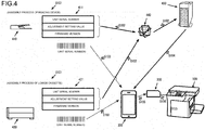
FIG. 4 illustrates an example of using the NFC tag inFIG. 1 . -
FIG. 5 illustrates steps of a writing process by which the portable terminal inFIG. 1 writes information to an NFC tag. -
FIG. 6 illustrates steps of a reading process by which the MFP side inFIG. 1 reads information of an NFC tag. - In the following, an embodiment of an electronic device of the present disclosure will be explained with reference to
FIG. 1 to FIG. 6 . In the following explanation, as an example of an electronic device, there is an MFP (Multifunctional Peripheral) that is a complex peripheral device equipped, for example, with a printing function, a copying function, a FAX function, a data transmission/reception function via a network, and the like, or a portable terminal such as a smartphone and the like. As the portable terminal, it is also possible to use a tablet terminal, laptop computer and the like. - First, as illustrated in
FIG. 1 , an NFC (Near Field Communications) tag (hereafter, referred to as a wireless tag) 200 is connected to anMFP 100. Thewireless tag 200 is connected to the MFP 100 by a wired connection (a serial bus such as a 12C bus and the like). Moreover, thewireless tag 200 is wirelessly connected to aportable terminal 300. - Although described in detail later, information that is stored in the
wireless tag 200 can be rewritten by theMFP 100 and theportable terminal 300. Furthermore, user-specific information or setup information for activating various application programs that are installed in theportable terminal 300, for example, can be written in thewireless tag 200 by theportable terminal 300. - Next, referring to
FIG. 2 , an example of the configuration of thewireless tag 200 and theportable terminal 300 will be explained. First, the MFP 100 includes acontrol unit 110 that controls aprinter unit 101, an I/F (interface) 102, apanel unit 103, and anHDD 104. The MFP 100 may also include a scanner unit, a FAX unit and the like. - The
printer unit 101 is a device that prints images on paper based on printing data that is outputted from thecontrol unit 110. The I/F 102 is in charge of communication with thewireless tag 200. The I/F 102 is in charge of communication with theportable terminal 300 via a network such as a LAN (Local Area Network). Moreover, the I/F 102 may also be in charge of communication with a content server, a webserver and the like. Thepanel unit 103 is a device such as a touch panel for performing a display for the printing function, the copying function, the FAX function, the data transmission/reception function via a network, and for various settings of theMFP 100. The HDD 104 is a storage device for storing application programs and the like for providing the various functions of theMFP 100. Furthermore, the HDD 104 has, for example, user boxes that store printing jobs that are registered from user terminals. - The
control unit 110 is a processor that controls the overall operation of the MFP 100 by executing an image-forming program, control program and the like. Thecontrol unit 110 includes a printer-control unit 111, a communication-control unit 112, aRAM 113, aROM 114, an image-processing unit 115, a panel-operation-control unit 116, an HDD-control unit 117 and a system-control unit 118. Moreover, these are connected to adatabase 119. - The printer-
control unit 111 controls the printing operation of theprinter unit 101. The communication-control unit 112 controls transmission/reception with thewireless tag 200 and the like via the I/F 102. TheRAM 113 is a work memory for executing programs. A control program for checking the operation of each unit and the like is stored in theROM 114. The image-processing unit 115 performs image processing (rasterization) on a printing job that is registered in a user box of theHDD 104, for example. The system-control unit 118 causes printing data that has undergone image processing by the image-processing unit 115 to be stored temporarily in theRAM 113. - The panel-operation-
control unit 116 controls the display operation of thepanel unit 103. Moreover, the panel-operation-control unit 116, via thepanel unit 103, receives start settings and the like for printing, copying, FAX, data transmission/reception via a network and the like. The HDD-control unit 117 controls reading data from and writing data to theHDD 104. - The system-
control unit 118 controls the cooperative operation of each unit. Although described in detail later, the system-control unit 118 reads, for example, setup information or the like that is written in thewireless tag 200, and executes setup and the like. - The
wireless tag 200 includes acontrol unit 210 that controls the I/F 201. The I/F 201 is in charge of communication with theMFP 100. Thecontrol unit 210 has anantenna unit 211 and anIC chip 212. Theantenna unit 211 performs communication with theportable terminal 300 using a specific frequency (for example, 13.56 MHz). TheIC chip 212 has a non-volatile memory that stores NFC user data and the like that will be described later. Moreover, theIC chip 212 writes information received via the I/F 201 orantenna unit 211 to the non-volatile memory, and transmits information in the non-volatile memory via the I/F 201 orantenna unit 211. The information in the non-volatile memory is written in a format that is defined according to the NFC standard. - The
portable terminal 300 includes acontrol unit 310 that controls anantenna 301 and apanel unit 302. Theantenna 301 is in charge of communication with thewireless tag 200 and the like. Theantenna 301 is in charge of communication with theMFP 100, a content server, a web server and the like via a network. Thepanel unit 302 is a device such as a touch panel for selecting the various functions of theportable terminal 300, inputting text, displaying information and the like. - The
control unit 310 is a processor that controls the overall operation of theportable terminal 300 by executing application programs and control programs. Thecontrol unit 310 includes a communication-control unit 311, aRAM 312, aROM 313, a panel-operation-control unit 314 and a system-control unit 315. Moreover, these units are connected to adata bus 316. - The communication-
control unit 311 performs control of transmission and reception with thewireless tag 200,MFP 100 and the like via theantenna 301. TheRAM 312 is a work memory for executing programs. A control program for checking the operation of each unit and the like is stored in theROM 313. The panel-operation-control unit 314 controls the display operation and the like of thepanel unit 302. - The system-
control unit 315 controls the cooperative operation and the like of each unit. Moreover, the system-control unit 315 has a wireless tag reader/writer function, and when there is an instruction via thepanel unit 302 to read or write the information of thewireless tag 200, the system-control unit 315 transmits a radio wave to the communication-control unit 311 from theantenna 301. - Next, the configuration of the
wireless tag 200 will be explained with reference toFIG. 3 . First, data is written to thewireless tag 200 in a format that is defined according to the NFC standard. Thewireless tag 200 has, for example, NFC information (1) that has anarea 221 where NFC user data is written and anempty area 222, and NFC information (2) that has asystem area 223. The NFC information (1) and the NFC information (2) are management information for managing areas where data is written and the like. In other words, NFC information (1) has, for example, the size ofarea 201 where NFC user data is written, and the size of theempty area 222. Moreover, the NFC information (2) has, for example, the size of thesystem area 223. Device information of theMFP 100 is written in thearea 221 where the NFC user data is written. The machine name, wired and wireless connection information for a network, and the like are written, for example, as device information. - As illustrated in
FIG. 3B , setup information (1), setup information (2) and the like can be written in theempty area 222 of the NFC information (1). The setup information (1) and setup information (2) each have different information contents related to setup.FIG. 3A to FIG. 3D are enlarged views of theempty area 222, and illustrate the state of the setup information (1) and the setup information (2) being written in theempty area 222. In this state, the empty area is an area that excludes the area where the setup information (1) and setup information (2) are stored. - Here, as illustrated in
FIG. 3C for example, the setup information (1) has, for example, a header and data. The header includes, for example, start of tag information, data size, setup type, post-setup processing, and status information. The data includes setup data. - Details of the header and data in
FIG. 3C are as illustrated inFIG. 3D . That is, the start of tag information indicates that starting position of the setup data. The data size indicates the effective size of the setup information. The setup type indicates what kind of setup is to be performed. Post-setup processing indicates how setup data will be handled after setup is complete (for example, deletion, storage in theHDD 104 or the like). The status information indicates whether setup is incomplete, complete or failed. The setup data indicates information required for setup. For example, the ID number and serial number of the mounted unit, adjustment information, connection information with an external server, and the like are written in the setup information (1). More specifically, the setup type, indicates, for example, performing settings of the mounted unit that corresponds to the ID number and serial number in the setup data to a default value based on adjustment information and the like, or performing connection settings based on connection information. - Next, an example of a method for using the
wireless tag 200 will be explained with reference toFIG. 4 . InFIG. 4 , reference number 410 indicates a reading device,reference number 420 indicates a lower cassette,reference number 430 indicates a database server, andreference number 440 indicates a network such as the Internet. Moreover, the reading device 410 and thelower cassette 420 are prepared as options of theMFP 100. Options of theMFP 100 besides the reading device 410 andlower cassette 420, such as a finisher that is capable of sorting and stapling when printing plural copies may also be prepared, however, an explanation of other options will be omitted here. - An external terminal constructs
information lower cassette 420. - A unit serial number, adjustment setting values, firmware version and the like of the reading unit 410, for example, are included in the
information 411. Moreover, a unit serial number, adjustment setting values, firmware version and the like of thelower cassette 420, for example, are included in theinformation 421. - When constructing the
information lower cassette 420. Furthermore, these barcodes may be printed in or affixed to the instruction manuals of the reading device 410 andlower cassette 420. - An external terminal, via a
network 440, registers theinformation lower cassette 420 in thedatabase server 430. - The
portable terminal 300 reads each of the barcodes 412, 422, and obtains the respective unit serial numbers. - The
portable terminal 300 accesses thedatabase server 430 based on the obtained unit serial numbers, and obtains theinformation lower cassette 420. - The
portable terminal 300 writes the obtainedinformation lower cassette 420 to thewireless tag 200. - In this case, the
portable terminal 300 writes theinformation 411 related to the assembly process of the reading device 410 as the setup information (1) inFIG. 3B , for example. - Moreover, the
portable terminal 300 writes theinformation 421 related to the assembly process of thelower cassette 420 as the setup information (2) inFIG. 3B , for example. - The
MFP 100 reads, for example, the setup information (1), (2) inFIG. 3B , and executes setup. - The timing at which the
MFP 100 reads the setup information (1), (2) may be when the power to theMFP 100 is turned ON, or may be when a read instruction from reading the setup information (1), (2) is given from thepanel unit 103 or theportable terminal 300. - In step S105, the
portable terminal 300 may write the respective unit serial numbers to thewireless tag 200, and in step S106, theMFP 100 may access thedatabase server 430 and obtain theinformation 411, 412 related to the assembly processes of the reading device 410 andlower cassette 420. - Next, processing on the
portable terminal 300 side will be explained with reference toFIG. 5 . In the following, the case of writing theinformation lower cassette 420 illustrated inFIG. 4 , for example, to theempty area 222 of thewireless tag 200 will be explained. - The system-
control unit 315 reads thewireless tag 200. - In this case, the system-
control unit 315, via the communication-control unit 311, reads thewireless tag 200 by near field communication with thewireless tag 200. - The system-
control unit 315 determines whether or not there is anempty area 222 in thewireless tag 200. - In this case, the system-
control unit 315, by using near field communication with thewireless tag 200, reads the size of theempty area 222 of the NFC information (1) illustrated inFIG. 3 , for example, and when the system-control unit 315 determines that there is an empty area 222 (step S202: YES), proceeds to step S206. - However, when the system-
control unit 315 determines that there is no empty area 222 (step S202: NO), the system-control unit proceeds to step S203. - The system-
control unit 315 reads the status information of thewireless tag 200. - In this case, the system-
control unit 315 uses near field communication with thewireless tag 200 to read status information that is written in the header of the setup information (1) that is illustrated inFIG. 3 for example. - The system-
control unit 315 determines whether or not the status is "setup incomplete". - In this case, when the status information indicates that setup is complete or that setup is failed, the system-
control unit 315 determines that the status is not "setup incomplete" (step S204: NO), and proceeds to step S206. - However, when the status information indicates that setup is incomplete, the
system control unit 315 determines that the status is "setup incomplete" (step S204: YES), and proceeds to step S205. - The system-
control unit 315 displays that there is noempty area 222. - In this case, the system-
control unit 315, via the panel-operation-control unit 314, causes thepanel unit 302 to display that there is noempty area 222. - The system-
control unit 315 cancels the writing password. - In this case, the system-
control unit 315 transmits a password that is inputted via thepanel unit 302 to thewireless tag 200. - The system-
control unit 315 determines whether or not cancellation is successful. - In this case, the system-
control unit 315, by using near field communication with thewireless tag 200, determines that cancellation is successful when the password is cancelled (step S207: YES), and proceeds to step S209. - However, the system-
control unit 315 determines that cancellation is not successful when the password is not cancelled (step S207: NO), and proceeds to step S208. - The system-
control unit 315 displays that authentication is failed. - In this case, the system-
control unit 315, via the panel-operation-control unit 314, causes thepanel unit 302 to display that authentication is failed. - The system-
control unit 315 writes setup information. - In this case, the system-
control unit 315, by using near field communication with thewireless tag 200, writes setup information (1) for example in theempty area 222 of thewireless tag 200. Moreover, when there is no empty space in thewireless tag 200, the system-control unit 315, by using near field communication with thewireless tag 200, may delete setup information that is already written in thewireless tag 200, and then write the setup information (1). - The contents of the setup information (1) may be, for example, the
information lower cassette 420 that were explained usingFIG. 4 . Moreover, the status information of the setup information (1) is "incomplete". - The information that is to be written in the
empty area 222 of thewireless tag 200 is not particularly limited. For example, user-specific information or the like for activating various application programs that are stored in theportable terminal 300 may be written. - The system-
control unit 315 determines whether or not writing is successful. - In this case, when the system-
control unit 315, by using near field communication with thewireless tag 200, determines that writing is successful (step S210: YES), the system-control unit 315 proceeds to step S212. - However, when the system-
control unit 315 determines that writing is not successful (step S210: NO), the system-control unit 315 proceeds to step S211. - The system-
control unit 315 displays that writing is failed. - In this case, the system-
control unit 315, via the panel-operation-control unit 314, causes thepanel unit 302 to display that writing is failed. - The system-
control unit 315 displays that writing is complete. - In this case, the system-
control unit 315, via the panel-operation-control unit 314, causes thepanel unit 302 to display that writing is complete. - Next, processing on the
MFP 100 side will be explained with reference toFIG. 6 . The processing described below is executed, for example when the power to theMFP 100 is turned ON. - The system-
control unit 118 read thewireless tag 200. - In this case, the system-
control unit 118, via the communication-control unit 112, reads thewireless tag 200 by communicating with thewireless tag 200 via a wired connection (serial bus such as a I2C bus). - The system-
control unit 118 determines whether or not there is setup information. - In this case, the system-
control unit 118 checks, for example, whether or not setup information (1) is written in theempty area 222 illustrated inFIG. 3 . When setup information (1) is written, the system-control unit 118 determines that there is setup information (step S302: YES), and proceeds to step S303. - However, when setup information (1) is not written, the system-
control unit 118 determines that there is no setup information (step S302: NO), and ends processing. - The system-
control unit 118 reads the status information. - In this case, the system-
control unit 118 reads, for example, the status information that is written in the header of the setup information (1). - The system-
control unit 118 determines whether or not the status is "setup incomplete". - In this case, when the status information that is written in the header of the setup information (1) indicates, for example, that setup is incomplete, the system-
control unit 118 determines that the status is "setup incomplete" (step S304: YES), and proceeds to step S305. - However, when the status indicates that setup is complete or the setup is failed, the system-
control unit 118 determines that the status is not "setup incomplete" (step S304: NO), and ends processing. - The system-
control unit 118 executes setup. - In this case, the system-
control unit 118 executes setup, for example, based on theinformation lower cassette 420 that is written by theportable terminal 300. - The system-
control unit 118 determines whether or not setup is successful. - In this case, when setting based on adjustment setting values and the like included in the
information control unit 118 determines that setup is not successful (step S306: NO), and proceeds to step S309. - However, when setting based on the adjustment setting values and the like included in the
information control unit 118 determines that setup is successful (step S306: YES), and proceeds to step S307. - The system-
control unit 118 sets the status information to "complete". - In this case, the system-
control unit 118 writes "complete" in the status information of the header of the setup information (1) illustrated inFIG. 3 , for example. - The system-
control unit 118 displays that setup is successful, - In this case, the system-
control unit 118, via the panel-operation-control unit 116, causes thepanel unit 103 to display that setup is successful. - The system-
control unit 118 sets the status information to "failure". - In this case, the system-
control unit 118 writes "failure" in the status information of the header of the setup information (1) illustrated inFIG. 3 , for example. - The system-
control unit 118 displays that setup is failed. - In this case, the system-
control unit 118, via the panel-operation-control unit 116, causes thepanel unit 103 to display that setup is failed. - In this way, in the present embodiment, when the electronic device is, for example, the
MFP 100, the system-control unit 118 (first system-control unit), via the communication-control unit 112 (first communication-control unit), checks whether or not setup information is stored in thewireless tag 200. The communication-control unit 112 controls communication with thewireless tag 200 that is capable of storing setup information that has status information that indicates the setup state. When setup information is stored, the system-control unit 118 reads the setup information, executes setup based on that setup information, and writes status information that corresponds to the setup state. - Moreover, when the electronic device is, for example, the
portable terminal 300, the system-control unit 315 (second system-control unit), via the communication-control unit 311 (second communication-control unit), reads NFC information (management information). The communication-control unit 311 controls communication with thewireless tag 200. The NFC information (management information) manages the data write area of thewireless tag 200. When there is anempty area 222 in the NFC information (management information), the system-control unit 315 writes setup information that has status information indicating the setup state in theempty area 222. - In this way, the
portable terminal 300 writes setup information to theempty area 222 of thewireless tag 200, and theMFP 100 rewrites the status information of the setup information, so it is possible to effectively use thewireless tag 200. - Furthermore, the
MFP 100 executes setup based on the setup information that is written in thewireless tag 200, so it is possible to omit the adjustment setting or the network connection setting via thepanel unit 103. - The
portable terminal 300 can also write arbitrary information other than setup information in theempty area 222 of thewireless tag 200. - In a typical printing system described above, by notifying a client PC that is spooling job information of information related to the output destination and printing settings that are read from an IC tag that is attached to a printer by a portable terminal, the printing process is executed by the printer, so giving printing instructions to the printer becomes easy.
- Incidentally, NFC (Near Field Communication) information is written in a format that is defined by NFC Forum in a data storage area of an NFC tag that is one standard of an IC tag that is attached to a printer, for example. Moreover, it is possible to read NFC information from a terminal that supports NFC. However, when the amount of data of NFC information is less than the storage area that is prepared as the NFC tag, a lot of empty area will be present and there is a problem in that effective use may not be possible.
- With the electronic device and information update method of the present disclosure, it is possible to write setup information in the empty area of a wireless tag, and rewrite status information of the setup information, so it is possible to effectively use the wireless tag.
- In the present embodiment, the case of applying the electronic device of the present disclosure to an
MFP 100 was explained, however, the electronic device could also be applied to an information device such as a PC (Personal Computer), household appliance and the like.
Claims (6)
- An electronic device (100), characterized in that:a first communication-control unit (112) that controls communication with a wireless tag (200) that is capable of storing setup information that has status information indicating a setup state; anda first system-control unit (118) that checks via the first communication-control unit (112) whether or not the setup information is stored in the wireless tag (200), and when the setup information is stored, reads the setup information; whereinthe first system-control unit (118) executes setup based on the setup information, and rewrites the status information to correspond to the setup state.
- The electronic device (100) according to Claim 1, characterized in that
when the setup is incomplete, complete or failed, the first system-control unit (118) sets the status information to setup incomplete, setup complete, or setup failure. - An electronic device (300) characterized in that:a second communication-control unit (311) that controls communication with a wireless tag (200); anda second system-control unit (315) that via the second communication-control unit (311) reads management information that manages the data write area of the wireless tag (200); whereinwhen there is empty area (222) in the management information, the second system-control unit (315) writes setup information that has status information indicating the setup state in the empty area (222).
- The electronic device (300) according to Claim 3, characterized in that
when there is no empty area (222) in the management information, the second system-control unit (315) writes new setup information in the setup information for setup complete or setup failed when rewriting the status information to either setup complete or setup failed. - An information update method that causes a computer that controls an electronic device (100) to execute:a step for controlling communication with a wireless tag (200) that is capable of storing setup information having status information that indicates a setup state;a step for checking whether or not the setup information is stored in the wireless tag (200), and when the setup information is stored, reading the setup information; anda step for executing setup based on the setup information, and rewriting the status information to correspond to the setup state.
- An information update method that causes a computer that controls an electronic device (300) to execute:a step of controlling communication with a wireless tag (200);a step of reading management information for managing a data write area of the wireless tag (200); andwhen there is an empty area (222) in the management information,a step of writing setup information having status information that indicates a setup state in the empty area (222).
Applications Claiming Priority (1)
| Application Number | Priority Date | Filing Date | Title |
|---|---|---|---|
| JP2016142963A JP2018013951A (en) | 2016-07-21 | 2016-07-21 | Electronic apparatus and information update program |
Publications (2)
| Publication Number | Publication Date |
|---|---|
| EP3273341A1 true EP3273341A1 (en) | 2018-01-24 |
| EP3273341B1 EP3273341B1 (en) | 2021-05-05 |
Family
ID=59101317
Family Applications (1)
| Application Number | Title | Priority Date | Filing Date |
|---|---|---|---|
| EP17176959.9A Active EP3273341B1 (en) | 2016-07-21 | 2017-06-20 | Electronic device and information update method |
Country Status (4)
| Country | Link |
|---|---|
| US (2) | US10120631B2 (en) |
| EP (1) | EP3273341B1 (en) |
| JP (1) | JP2018013951A (en) |
| CN (1) | CN107645320B (en) |
Families Citing this family (5)
| Publication number | Priority date | Publication date | Assignee | Title |
|---|---|---|---|---|
| EP3809331A4 (en) * | 2018-06-14 | 2022-03-02 | Kyocera Corporation | RFID TAG AND RFID TAG SYSTEM |
| JP7479992B2 (en) | 2020-08-14 | 2024-05-09 | 東芝テック株式会社 | Image forming device |
| JP7533111B2 (en) | 2020-10-20 | 2024-08-14 | 沖電気工業株式会社 | Information processing device |
| JP7251539B2 (en) | 2020-12-10 | 2023-04-04 | セイコーエプソン株式会社 | Projector control method, projector, and display system |
| JP2023030312A (en) | 2021-08-23 | 2023-03-08 | セイコーエプソン株式会社 | Display device and display device control method |
Citations (1)
| Publication number | Priority date | Publication date | Assignee | Title |
|---|---|---|---|---|
| US20130215467A1 (en) * | 2012-02-21 | 2013-08-22 | Zih Corp. | Method and apparatus for implementing near field communications with a printer |
Family Cites Families (20)
| Publication number | Priority date | Publication date | Assignee | Title |
|---|---|---|---|---|
| US3979726A (en) * | 1974-04-10 | 1976-09-07 | Honeywell Information Systems, Inc. | Apparatus for selectively clearing a cache store in a processor having segmentation and paging |
| JPH04307647A (en) * | 1991-04-04 | 1992-10-29 | Fuji Photo Film Co Ltd | Memory card storage control system |
| JP3471827B2 (en) * | 1992-09-08 | 2003-12-02 | 富士写真フイルム株式会社 | IC memory card control method and device |
| US7312441B2 (en) * | 2004-07-02 | 2007-12-25 | Thermo Finnigan Llc | Method and apparatus for controlling the ion population in a mass spectrometer |
| US20060169769A1 (en) * | 2005-02-02 | 2006-08-03 | Leap-Up Llc | Intelligent manager for automatically handling and managing media |
| JP4826107B2 (en) * | 2005-03-14 | 2011-11-30 | 富士ゼロックス株式会社 | Pallet reuse system, pallet reuse system management method, and pallet reuse system management program |
| JP4301301B2 (en) * | 2007-02-05 | 2009-07-22 | ソニー株式会社 | Nonvolatile semiconductor memory device and management method thereof |
| US8595413B2 (en) * | 2008-02-20 | 2013-11-26 | Sony Corporation | Memory control method and device, memory access control method, computer program, and recording medium |
| JP2009300544A (en) * | 2008-06-10 | 2009-12-24 | Konica Minolta Business Technologies Inc | Setting information imparting device, image processor and setting information imparting method |
| JP5955041B2 (en) | 2012-03-09 | 2016-07-20 | キヤノン株式会社 | Printing system and method |
| CN104704769B (en) * | 2012-10-15 | 2018-07-27 | 皇家飞利浦有限公司 | Wireless communication system |
| US20150038213A1 (en) * | 2013-07-30 | 2015-02-05 | Ainsworth Game Technology Limited | Electronic gaming machine and method |
| WO2015038104A1 (en) * | 2013-09-11 | 2015-03-19 | Hewlett-Packard Development Company, L.P. | Near field communication (nfc) data transfer |
| KR20150040669A (en) * | 2013-10-07 | 2015-04-15 | 삼성전자주식회사 | Method and Apparatus for customizing a configuration of printing application |
| JP6071949B2 (en) * | 2014-06-25 | 2017-02-01 | キヤノン株式会社 | Information processing apparatus, control method thereof, and program |
| CN104142979B (en) * | 2014-07-15 | 2017-07-25 | 武汉理工大学 | A kind of indexing means for realizing RFID tag storage management |
| JP6521618B2 (en) * | 2014-12-04 | 2019-05-29 | キヤノン株式会社 | Communication device control method and program |
| JPWO2016092702A1 (en) * | 2014-12-12 | 2017-09-21 | キヤノン株式会社 | COMMUNICATION DEVICE, COMMUNICATION DEVICE CONTROL METHOD, PROGRAM |
| JP6632239B2 (en) * | 2015-07-22 | 2020-01-22 | キヤノン株式会社 | Electronic device capable of wireless communication, control method thereof, and program |
| CN105631644B (en) * | 2015-12-31 | 2020-09-11 | 深圳市驰卡软件有限公司 | Method for equipment production control, NFC smart terminal |
-
2016
- 2016-07-21 JP JP2016142963A patent/JP2018013951A/en active Pending
-
2017
- 2017-06-02 CN CN201710407686.XA patent/CN107645320B/en not_active Expired - Fee Related
- 2017-06-20 EP EP17176959.9A patent/EP3273341B1/en active Active
- 2017-06-23 US US15/631,681 patent/US10120631B2/en active Active
-
2018
- 2018-09-10 US US16/125,766 patent/US10338870B2/en active Active
Patent Citations (1)
| Publication number | Priority date | Publication date | Assignee | Title |
|---|---|---|---|---|
| US20130215467A1 (en) * | 2012-02-21 | 2013-08-22 | Zih Corp. | Method and apparatus for implementing near field communications with a printer |
Non-Patent Citations (1)
| Title |
|---|
| ANONYMOUS: "android - Confused about NFC tag size - Stack Overflow", STACK OVERFLOW IS A QUESTION AND ANSWER SITE FOR PROGRAMMERS, 20 August 2013 (2013-08-20), XP055433580, Retrieved from the Internet <URL:https://web.archive.org/web/20130820123425/https://stackoverflow.com/questions/18334956/confused-about-nfc-tag-size> [retrieved on 20171208] * |
Also Published As
| Publication number | Publication date |
|---|---|
| US20190018633A1 (en) | 2019-01-17 |
| CN107645320A (en) | 2018-01-30 |
| US10338870B2 (en) | 2019-07-02 |
| US10120631B2 (en) | 2018-11-06 |
| EP3273341B1 (en) | 2021-05-05 |
| JP2018013951A (en) | 2018-01-25 |
| US20180024796A1 (en) | 2018-01-25 |
| CN107645320B (en) | 2021-04-13 |
Similar Documents
| Publication | Publication Date | Title |
|---|---|---|
| US10338870B2 (en) | Electronic device suitable for writing information to wireless tag | |
| EP3062499B1 (en) | Mobile device that ensures function extension of image forming apparatus, image forming system, and recording medium | |
| US10310844B2 (en) | Electronic apparatus, version checking system and recording medium | |
| EP3557403B1 (en) | Image forming system and image forming method | |
| EP3070595A1 (en) | Information processing apparatus, program, output system, and output method | |
| CN108696658A (en) | Image formation system, server, image forming apparatus and image forming method | |
| US10382302B2 (en) | Electronic apparatus and non-transitory computer readable recording medium suitable for acquiring status information | |
| US20130021646A1 (en) | Printing apparatus | |
| EP2570916A2 (en) | Information processing system, information processing apparatus, and information processing method | |
| EP2966847A1 (en) | Image forming apparatus and image forming method | |
| US20190187937A1 (en) | Printing computing device for operating a multi-function printing device | |
| JP6136703B2 (en) | Information processing program and information processing apparatus | |
| CN105391893A (en) | Print apparatus and print system | |
| EP3336683A1 (en) | Image processing apparatus and method to form image on sheet using page image data and object information | |
| EP3322205A1 (en) | Electronic apparatus and non-transitory computer-readable recording medium | |
| US9977933B2 (en) | Electronic device suitable for writing information to wireless tags and information update method | |
| US20190238707A1 (en) | Image forming system, server, and image forming apparatus for updating internal data of an external device directly connected to the image forming apparatus | |
| US10628091B2 (en) | Image forming apparatus having function to perform authentication printing with user terminal device that does not have dedicated print driver, control method of image forming apparatus, and non-transitory computer readable storage medium storing control program of image forming apparatus | |
| EP3644191A1 (en) | Memory system and electronic device | |
| EP3416044A1 (en) | Image forming apparatus and control method of image forming apparatus | |
| JP5076442B2 (en) | Image processing device | |
| JP6406233B2 (en) | Information processing system | |
| JP6003967B2 (en) | Service processing apparatus and service processing program | |
| EP2056197A1 (en) | Image forming device, image formation controlling method, and image formation controlling program | |
| EP3270612A1 (en) | Image forming apparatus, image forming method, and method by the same |
Legal Events
| Date | Code | Title | Description |
|---|---|---|---|
| PUAI | Public reference made under article 153(3) epc to a published international application that has entered the european phase |
Free format text: ORIGINAL CODE: 0009012 |
|
| STAA | Information on the status of an ep patent application or granted ep patent |
Free format text: STATUS: THE APPLICATION HAS BEEN PUBLISHED |
|
| AK | Designated contracting states |
Kind code of ref document: A1 Designated state(s): AL AT BE BG CH CY CZ DE DK EE ES FI FR GB GR HR HU IE IS IT LI LT LU LV MC MK MT NL NO PL PT RO RS SE SI SK SM TR |
|
| AX | Request for extension of the european patent |
Extension state: BA ME |
|
| STAA | Information on the status of an ep patent application or granted ep patent |
Free format text: STATUS: REQUEST FOR EXAMINATION WAS MADE |
|
| 17P | Request for examination filed |
Effective date: 20180315 |
|
| RBV | Designated contracting states (corrected) |
Designated state(s): AL AT BE BG CH CY CZ DE DK EE ES FI FR GB GR HR HU IE IS IT LI LT LU LV MC MK MT NL NO PL PT RO RS SE SI SK SM TR |
|
| STAA | Information on the status of an ep patent application or granted ep patent |
Free format text: STATUS: EXAMINATION IS IN PROGRESS |
|
| 17Q | First examination report despatched |
Effective date: 20190220 |
|
| GRAP | Despatch of communication of intention to grant a patent |
Free format text: ORIGINAL CODE: EPIDOSNIGR1 |
|
| STAA | Information on the status of an ep patent application or granted ep patent |
Free format text: STATUS: GRANT OF PATENT IS INTENDED |
|
| RIC1 | Information provided on ipc code assigned before grant |
Ipc: H04B 5/00 20060101ALI20201030BHEP Ipc: G06F 3/12 20060101AFI20201030BHEP Ipc: H04L 29/08 20060101ALI20201030BHEP Ipc: H04W 4/80 20180101ALI20201030BHEP Ipc: H04W 4/00 20180101ALI20201030BHEP Ipc: G06K 7/10 20060101ALI20201030BHEP |
|
| INTG | Intention to grant announced |
Effective date: 20201118 |
|
| GRAS | Grant fee paid |
Free format text: ORIGINAL CODE: EPIDOSNIGR3 |
|
| GRAA | (expected) grant |
Free format text: ORIGINAL CODE: 0009210 |
|
| STAA | Information on the status of an ep patent application or granted ep patent |
Free format text: STATUS: THE PATENT HAS BEEN GRANTED |
|
| AK | Designated contracting states |
Kind code of ref document: B1 Designated state(s): AL AT BE BG CH CY CZ DE DK EE ES FI FR GB GR HR HU IE IS IT LI LT LU LV MC MK MT NL NO PL PT RO RS SE SI SK SM TR |
|
| REG | Reference to a national code |
Ref country code: GB Ref legal event code: FG4D |
|
| REG | Reference to a national code |
Ref country code: CH Ref legal event code: EP |
|
| REG | Reference to a national code |
Ref country code: AT Ref legal event code: REF Ref document number: 1390647 Country of ref document: AT Kind code of ref document: T Effective date: 20210515 |
|
| REG | Reference to a national code |
Ref country code: IE Ref legal event code: FG4D |
|
| REG | Reference to a national code |
Ref country code: DE Ref legal event code: R096 Ref document number: 602017037934 Country of ref document: DE |
|
| REG | Reference to a national code |
Ref country code: LT Ref legal event code: MG9D |
|
| REG | Reference to a national code |
Ref country code: AT Ref legal event code: MK05 Ref document number: 1390647 Country of ref document: AT Kind code of ref document: T Effective date: 20210505 |
|
| PG25 | Lapsed in a contracting state [announced via postgrant information from national office to epo] |
Ref country code: HR Free format text: LAPSE BECAUSE OF FAILURE TO SUBMIT A TRANSLATION OF THE DESCRIPTION OR TO PAY THE FEE WITHIN THE PRESCRIBED TIME-LIMIT Effective date: 20210505 Ref country code: BG Free format text: LAPSE BECAUSE OF FAILURE TO SUBMIT A TRANSLATION OF THE DESCRIPTION OR TO PAY THE FEE WITHIN THE PRESCRIBED TIME-LIMIT Effective date: 20210805 Ref country code: AT Free format text: LAPSE BECAUSE OF FAILURE TO SUBMIT A TRANSLATION OF THE DESCRIPTION OR TO PAY THE FEE WITHIN THE PRESCRIBED TIME-LIMIT Effective date: 20210505 Ref country code: FI Free format text: LAPSE BECAUSE OF FAILURE TO SUBMIT A TRANSLATION OF THE DESCRIPTION OR TO PAY THE FEE WITHIN THE PRESCRIBED TIME-LIMIT Effective date: 20210505 Ref country code: LT Free format text: LAPSE BECAUSE OF FAILURE TO SUBMIT A TRANSLATION OF THE DESCRIPTION OR TO PAY THE FEE WITHIN THE PRESCRIBED TIME-LIMIT Effective date: 20210505 |
|
| PG25 | Lapsed in a contracting state [announced via postgrant information from national office to epo] |
Ref country code: PT Free format text: LAPSE BECAUSE OF FAILURE TO SUBMIT A TRANSLATION OF THE DESCRIPTION OR TO PAY THE FEE WITHIN THE PRESCRIBED TIME-LIMIT Effective date: 20210906 Ref country code: NO Free format text: LAPSE BECAUSE OF FAILURE TO SUBMIT A TRANSLATION OF THE DESCRIPTION OR TO PAY THE FEE WITHIN THE PRESCRIBED TIME-LIMIT Effective date: 20210805 Ref country code: PL Free format text: LAPSE BECAUSE OF FAILURE TO SUBMIT A TRANSLATION OF THE DESCRIPTION OR TO PAY THE FEE WITHIN THE PRESCRIBED TIME-LIMIT Effective date: 20210505 Ref country code: SE Free format text: LAPSE BECAUSE OF FAILURE TO SUBMIT A TRANSLATION OF THE DESCRIPTION OR TO PAY THE FEE WITHIN THE PRESCRIBED TIME-LIMIT Effective date: 20210505 Ref country code: RS Free format text: LAPSE BECAUSE OF FAILURE TO SUBMIT A TRANSLATION OF THE DESCRIPTION OR TO PAY THE FEE WITHIN THE PRESCRIBED TIME-LIMIT Effective date: 20210505 Ref country code: LV Free format text: LAPSE BECAUSE OF FAILURE TO SUBMIT A TRANSLATION OF THE DESCRIPTION OR TO PAY THE FEE WITHIN THE PRESCRIBED TIME-LIMIT Effective date: 20210505 Ref country code: IS Free format text: LAPSE BECAUSE OF FAILURE TO SUBMIT A TRANSLATION OF THE DESCRIPTION OR TO PAY THE FEE WITHIN THE PRESCRIBED TIME-LIMIT Effective date: 20210905 Ref country code: GR Free format text: LAPSE BECAUSE OF FAILURE TO SUBMIT A TRANSLATION OF THE DESCRIPTION OR TO PAY THE FEE WITHIN THE PRESCRIBED TIME-LIMIT Effective date: 20210806 |
|
| REG | Reference to a national code |
Ref country code: NL Ref legal event code: MP Effective date: 20210505 |
|
| PG25 | Lapsed in a contracting state [announced via postgrant information from national office to epo] |
Ref country code: NL Free format text: LAPSE BECAUSE OF FAILURE TO SUBMIT A TRANSLATION OF THE DESCRIPTION OR TO PAY THE FEE WITHIN THE PRESCRIBED TIME-LIMIT Effective date: 20210505 |
|
| PG25 | Lapsed in a contracting state [announced via postgrant information from national office to epo] |
Ref country code: SM Free format text: LAPSE BECAUSE OF FAILURE TO SUBMIT A TRANSLATION OF THE DESCRIPTION OR TO PAY THE FEE WITHIN THE PRESCRIBED TIME-LIMIT Effective date: 20210505 Ref country code: SK Free format text: LAPSE BECAUSE OF FAILURE TO SUBMIT A TRANSLATION OF THE DESCRIPTION OR TO PAY THE FEE WITHIN THE PRESCRIBED TIME-LIMIT Effective date: 20210505 Ref country code: DK Free format text: LAPSE BECAUSE OF FAILURE TO SUBMIT A TRANSLATION OF THE DESCRIPTION OR TO PAY THE FEE WITHIN THE PRESCRIBED TIME-LIMIT Effective date: 20210505 Ref country code: CZ Free format text: LAPSE BECAUSE OF FAILURE TO SUBMIT A TRANSLATION OF THE DESCRIPTION OR TO PAY THE FEE WITHIN THE PRESCRIBED TIME-LIMIT Effective date: 20210505 Ref country code: EE Free format text: LAPSE BECAUSE OF FAILURE TO SUBMIT A TRANSLATION OF THE DESCRIPTION OR TO PAY THE FEE WITHIN THE PRESCRIBED TIME-LIMIT Effective date: 20210505 Ref country code: RO Free format text: LAPSE BECAUSE OF FAILURE TO SUBMIT A TRANSLATION OF THE DESCRIPTION OR TO PAY THE FEE WITHIN THE PRESCRIBED TIME-LIMIT Effective date: 20210505 Ref country code: ES Free format text: LAPSE BECAUSE OF FAILURE TO SUBMIT A TRANSLATION OF THE DESCRIPTION OR TO PAY THE FEE WITHIN THE PRESCRIBED TIME-LIMIT Effective date: 20210505 |
|
| REG | Reference to a national code |
Ref country code: CH Ref legal event code: PL |
|
| REG | Reference to a national code |
Ref country code: DE Ref legal event code: R097 Ref document number: 602017037934 Country of ref document: DE |
|
| REG | Reference to a national code |
Ref country code: BE Ref legal event code: MM Effective date: 20210630 |
|
| PLBE | No opposition filed within time limit |
Free format text: ORIGINAL CODE: 0009261 |
|
| STAA | Information on the status of an ep patent application or granted ep patent |
Free format text: STATUS: NO OPPOSITION FILED WITHIN TIME LIMIT |
|
| PG25 | Lapsed in a contracting state [announced via postgrant information from national office to epo] |
Ref country code: MC Free format text: LAPSE BECAUSE OF FAILURE TO SUBMIT A TRANSLATION OF THE DESCRIPTION OR TO PAY THE FEE WITHIN THE PRESCRIBED TIME-LIMIT Effective date: 20210505 Ref country code: LU Free format text: LAPSE BECAUSE OF NON-PAYMENT OF DUE FEES Effective date: 20210620 |
|
| 26N | No opposition filed |
Effective date: 20220208 |
|
| GBPC | Gb: european patent ceased through non-payment of renewal fee |
Effective date: 20210805 |
|
| PG25 | Lapsed in a contracting state [announced via postgrant information from national office to epo] |
Ref country code: LI Free format text: LAPSE BECAUSE OF NON-PAYMENT OF DUE FEES Effective date: 20210630 Ref country code: IE Free format text: LAPSE BECAUSE OF NON-PAYMENT OF DUE FEES Effective date: 20210620 Ref country code: CH Free format text: LAPSE BECAUSE OF NON-PAYMENT OF DUE FEES Effective date: 20210630 |
|
| PG25 | Lapsed in a contracting state [announced via postgrant information from national office to epo] |
Ref country code: IS Free format text: LAPSE BECAUSE OF FAILURE TO SUBMIT A TRANSLATION OF THE DESCRIPTION OR TO PAY THE FEE WITHIN THE PRESCRIBED TIME-LIMIT Effective date: 20210905 Ref country code: FR Free format text: LAPSE BECAUSE OF NON-PAYMENT OF DUE FEES Effective date: 20210705 Ref country code: AL Free format text: LAPSE BECAUSE OF FAILURE TO SUBMIT A TRANSLATION OF THE DESCRIPTION OR TO PAY THE FEE WITHIN THE PRESCRIBED TIME-LIMIT Effective date: 20210505 |
|
| PG25 | Lapsed in a contracting state [announced via postgrant information from national office to epo] |
Ref country code: IT Free format text: LAPSE BECAUSE OF FAILURE TO SUBMIT A TRANSLATION OF THE DESCRIPTION OR TO PAY THE FEE WITHIN THE PRESCRIBED TIME-LIMIT Effective date: 20210505 Ref country code: GB Free format text: LAPSE BECAUSE OF NON-PAYMENT OF DUE FEES Effective date: 20210805 Ref country code: BE Free format text: LAPSE BECAUSE OF NON-PAYMENT OF DUE FEES Effective date: 20210630 |
|
| PGFP | Annual fee paid to national office [announced via postgrant information from national office to epo] |
Ref country code: DE Payment date: 20220505 Year of fee payment: 6 |
|
| PG25 | Lapsed in a contracting state [announced via postgrant information from national office to epo] |
Ref country code: HU Free format text: LAPSE BECAUSE OF FAILURE TO SUBMIT A TRANSLATION OF THE DESCRIPTION OR TO PAY THE FEE WITHIN THE PRESCRIBED TIME-LIMIT; INVALID AB INITIO Effective date: 20170620 |
|
| P01 | Opt-out of the competence of the unified patent court (upc) registered |
Effective date: 20230420 |
|
| PG25 | Lapsed in a contracting state [announced via postgrant information from national office to epo] |
Ref country code: CY Free format text: LAPSE BECAUSE OF FAILURE TO SUBMIT A TRANSLATION OF THE DESCRIPTION OR TO PAY THE FEE WITHIN THE PRESCRIBED TIME-LIMIT Effective date: 20210505 |
|
| REG | Reference to a national code |
Ref country code: DE Ref legal event code: R119 Ref document number: 602017037934 Country of ref document: DE |
|
| PG25 | Lapsed in a contracting state [announced via postgrant information from national office to epo] |
Ref country code: MK Free format text: LAPSE BECAUSE OF FAILURE TO SUBMIT A TRANSLATION OF THE DESCRIPTION OR TO PAY THE FEE WITHIN THE PRESCRIBED TIME-LIMIT Effective date: 20210505 Ref country code: DE Free format text: LAPSE BECAUSE OF NON-PAYMENT OF DUE FEES Effective date: 20240103 |
|
| PG25 | Lapsed in a contracting state [announced via postgrant information from national office to epo] |
Ref country code: MT Free format text: LAPSE BECAUSE OF FAILURE TO SUBMIT A TRANSLATION OF THE DESCRIPTION OR TO PAY THE FEE WITHIN THE PRESCRIBED TIME-LIMIT Effective date: 20210505 |
|
| PG25 | Lapsed in a contracting state [announced via postgrant information from national office to epo] |
Ref country code: TR Free format text: LAPSE BECAUSE OF FAILURE TO SUBMIT A TRANSLATION OF THE DESCRIPTION OR TO PAY THE FEE WITHIN THE PRESCRIBED TIME-LIMIT Effective date: 20210505 |