EP3644191A1 - Memory system and electronic device - Google Patents
Memory system and electronic device Download PDFInfo
- Publication number
- EP3644191A1 EP3644191A1 EP18820023.2A EP18820023A EP3644191A1 EP 3644191 A1 EP3644191 A1 EP 3644191A1 EP 18820023 A EP18820023 A EP 18820023A EP 3644191 A1 EP3644191 A1 EP 3644191A1
- Authority
- EP
- European Patent Office
- Prior art keywords
- volatile memory
- ram
- information
- control unit
- related information
- Prior art date
- Legal status (The legal status is an assumption and is not a legal conclusion. Google has not performed a legal analysis and makes no representation as to the accuracy of the status listed.)
- Withdrawn
Links
Images

Classifications
-
- G—PHYSICS
- G06—COMPUTING; CALCULATING OR COUNTING
- G06F—ELECTRIC DIGITAL DATA PROCESSING
- G06F3/00—Input arrangements for transferring data to be processed into a form capable of being handled by the computer; Output arrangements for transferring data from processing unit to output unit, e.g. interface arrangements
- G06F3/06—Digital input from, or digital output to, record carriers, e.g. RAID, emulated record carriers or networked record carriers
- G06F3/0601—Interfaces specially adapted for storage systems
- G06F3/0628—Interfaces specially adapted for storage systems making use of a particular technique
- G06F3/0655—Vertical data movement, i.e. input-output transfer; data movement between one or more hosts and one or more storage devices
- G06F3/0659—Command handling arrangements, e.g. command buffers, queues, command scheduling
-
- G—PHYSICS
- G06—COMPUTING; CALCULATING OR COUNTING
- G06F—ELECTRIC DIGITAL DATA PROCESSING
- G06F12/00—Accessing, addressing or allocating within memory systems or architectures
- G06F12/02—Addressing or allocation; Relocation
- G06F12/0223—User address space allocation, e.g. contiguous or non contiguous base addressing
- G06F12/023—Free address space management
- G06F12/0238—Memory management in non-volatile memory, e.g. resistive RAM or ferroelectric memory
- G06F12/0246—Memory management in non-volatile memory, e.g. resistive RAM or ferroelectric memory in block erasable memory, e.g. flash memory
-
- G—PHYSICS
- G06—COMPUTING; CALCULATING OR COUNTING
- G06F—ELECTRIC DIGITAL DATA PROCESSING
- G06F12/00—Accessing, addressing or allocating within memory systems or architectures
- G06F12/02—Addressing or allocation; Relocation
- G06F12/08—Addressing or allocation; Relocation in hierarchically structured memory systems, e.g. virtual memory systems
- G06F12/0802—Addressing of a memory level in which the access to the desired data or data block requires associative addressing means, e.g. caches
- G06F12/0866—Addressing of a memory level in which the access to the desired data or data block requires associative addressing means, e.g. caches for peripheral storage systems, e.g. disk cache
- G06F12/0868—Data transfer between cache memory and other subsystems, e.g. storage devices or host systems
-
- G—PHYSICS
- G06—COMPUTING; CALCULATING OR COUNTING
- G06F—ELECTRIC DIGITAL DATA PROCESSING
- G06F3/00—Input arrangements for transferring data to be processed into a form capable of being handled by the computer; Output arrangements for transferring data from processing unit to output unit, e.g. interface arrangements
- G06F3/06—Digital input from, or digital output to, record carriers, e.g. RAID, emulated record carriers or networked record carriers
- G06F3/0601—Interfaces specially adapted for storage systems
- G06F3/0602—Interfaces specially adapted for storage systems specifically adapted to achieve a particular effect
- G06F3/061—Improving I/O performance
- G06F3/0611—Improving I/O performance in relation to response time
-
- G—PHYSICS
- G06—COMPUTING; CALCULATING OR COUNTING
- G06F—ELECTRIC DIGITAL DATA PROCESSING
- G06F3/00—Input arrangements for transferring data to be processed into a form capable of being handled by the computer; Output arrangements for transferring data from processing unit to output unit, e.g. interface arrangements
- G06F3/06—Digital input from, or digital output to, record carriers, e.g. RAID, emulated record carriers or networked record carriers
- G06F3/0601—Interfaces specially adapted for storage systems
- G06F3/0602—Interfaces specially adapted for storage systems specifically adapted to achieve a particular effect
- G06F3/0614—Improving the reliability of storage systems
- G06F3/0616—Improving the reliability of storage systems in relation to life time, e.g. increasing Mean Time Between Failures [MTBF]
-
- G—PHYSICS
- G06—COMPUTING; CALCULATING OR COUNTING
- G06F—ELECTRIC DIGITAL DATA PROCESSING
- G06F3/00—Input arrangements for transferring data to be processed into a form capable of being handled by the computer; Output arrangements for transferring data from processing unit to output unit, e.g. interface arrangements
- G06F3/06—Digital input from, or digital output to, record carriers, e.g. RAID, emulated record carriers or networked record carriers
- G06F3/0601—Interfaces specially adapted for storage systems
- G06F3/0668—Interfaces specially adapted for storage systems adopting a particular infrastructure
- G06F3/0671—In-line storage system
- G06F3/0683—Plurality of storage devices
- G06F3/0685—Hybrid storage combining heterogeneous device types, e.g. hierarchical storage, hybrid arrays
-
- G—PHYSICS
- G06—COMPUTING; CALCULATING OR COUNTING
- G06F—ELECTRIC DIGITAL DATA PROCESSING
- G06F2212/00—Indexing scheme relating to accessing, addressing or allocation within memory systems or architectures
- G06F2212/10—Providing a specific technical effect
- G06F2212/1032—Reliability improvement, data loss prevention, degraded operation etc
-
- G—PHYSICS
- G06—COMPUTING; CALCULATING OR COUNTING
- G06F—ELECTRIC DIGITAL DATA PROCESSING
- G06F2212/00—Indexing scheme relating to accessing, addressing or allocation within memory systems or architectures
- G06F2212/72—Details relating to flash memory management
- G06F2212/7203—Temporary buffering, e.g. using volatile buffer or dedicated buffer blocks
-
- G—PHYSICS
- G06—COMPUTING; CALCULATING OR COUNTING
- G06F—ELECTRIC DIGITAL DATA PROCESSING
- G06F2212/00—Indexing scheme relating to accessing, addressing or allocation within memory systems or architectures
- G06F2212/72—Details relating to flash memory management
- G06F2212/7206—Reconfiguration of flash memory system
Definitions
- the present invention relates to a memory system and an electronic apparatus in which use of a non-volatile memory is suitable.
- an image forming apparatus such as an MFP (Multifunction Peripheral) and the like, which is one kind of electronic apparatus, is equipped with various consumable parts.
- a print function, a copy function, a FAX function, a data transmission/reception function via a network, and the like are installed, unit parts that execute these respective functions correspond as consumable parts.
- a rewritable non-volatile memory, a volatile memory used as a work memory for executing a program, and the like also correspond as consumable parts.
- counter information for determining the replacement time or the like of each unit part, setting information related to each function, and the like are stored.
- the above-described setting information, counter information, and the like stored in the non-volatile memory are read from the non-volatile memory and expanded in the volatile memory.
- the power-ON state when the above-described counter information is changed or the settings of the various functions are changed, the changed contents are stored in the volatile memory.
- the power of the image forming apparatus is turned OFF, the changed contents stored in the volatile memory are written to the non-volatile memory.
- the changed contents stored in the volatile memory are written to the non-volatile memory each time the image forming apparatus is switched from power ON to power OFF. Therefore, when the power to the image forming apparatus is frequently switched between ON and OFF, the number of times that the changed contents are written to the non-volatile memory is increased, and the life of the non-volatile memory is shortened.
- Patent Literature 1 proposes a control apparatus for automobiles that, when the key switch is turned OFF, only writes data to the non-volatile memory in a case where the contents of the volatile memory and the contents of the non-volatile memory are compared, and there is a difference between the data of both.
- Patent Literature 1 JP H11-141391 A
- the writing of data to the non-volatile memory is performed only when there is a difference between the contents of the volatile memory and the contents of the non-volatile memory, so the number of times that writing is performed may be reduced.
- the respective structures and the like are different, so the methods of reading and writing the respective data are different.
- the speed of reading and writing data in a non-volatile memory is slower than the speed of reading and writing data in a volatile memory.
- an object of the present invention is to provide a memory system and an electronic apparatus capable of solving the problems described above.
- the memory system includes: a non-volatile memory; a first volatile memory in which apparatus use related information stored in the non-volatile memory and that is related to use of an apparatus is written; a second volatile memory in which the apparatus use related information stored in the non-volatile memory is written; a memory management unit that manages a storage area for the apparatus use related information written in the first volatile memory so as to be updatable, and manages a storage area for the apparatus use related information written in the second volatile memory so as not to be updatable; and a system control unit that writes the apparatus use related information read from the non-volatile memory to the first volatile memory and the second volatile memory in accordance with turning power ON; wherein the system control unit, when a change in contents of the apparatus use related information occurs, rewrites the apparatus use related information in the first volatile memory according to the changed contents; and when the power is turned OFF, reads and compares the apparatus use related information in the first volatile memory with the apparatus use related information in the second volatile memory, and
- the electronic apparatus includes: a non-volatile memory; a first volatile memory in which apparatus use related information stored in the non-volatile memory and that is related to use of an apparatus is written; a second volatile memory in which the apparatus use related information stored in the non-volatile memory is written; a memory management unit that manages a storage area for the apparatus use related information written in the first volatile memory so as to be updatable, and manages a storage area for the apparatus use related information written in the second volatile memory so as not to be updatable; and a system control unit that writes the apparatus use related information read from the non-volatile memory to the first volatile memory and the second volatile memory in accordance with turning power ON; wherein the system control unit, when a change in contents of the apparatus use related information occurs, rewrites the apparatus use related information in the first volatile memory according to the changed contents; and when the power is turned OFF, reads and compares the apparatus use related information in the first volatile memory with the apparatus use related information in the second volatile memory, and
- the non-volatile memory stores apparatus use related information related to use of an apparatus
- the first volatile memory stores apparatus use related information
- the second volatile memory stores apparatus use related information
- the memory management unit manages a storage area in the first volatile memory for the apparatus use related information so as to be updatable and manages a storage area in the second volatile memory for the apparatus use related information so as not to be updatable
- the system control unit when the power is turned ON, writes the apparatus use related information read from the non-volatile memory to the first volatile memory and the second volatile memory.
- the system control unit when a change in the contents of the apparatus use related information occurs, rewrites the apparatus use related information in the first volatile memory in accordance to the changed contents, and when the power is turned OFF, reads and compares the apparatus use related information in the first volatile memory with the apparatus use related information in the second volatile memory, and writes only the different information to the non-volatile memory.
- the first volatile memory and the second volatile memory have shorter information read/write times than the non-volatile memory. Therefore, when the power is turned OFF, the system control unit may perform reading and comparison of the apparatus use related information in the first volatile memory and the apparatus use related information in the second volatile memory in a short time. In addition, when the power is turned OFF, the system control unit writes only the different information to the non-volatile memory, so the number of times of writing information to the non-volatile memory may be reduced, and the amount of information written to the non-volatile memory may be reduced.
- comparison of the apparatus use related information in the first volatile memory and the apparatus use related information in the second volatile memory by the system control unit may be performed in a short time, as well as the number of times of writing information to the non-volatile memory may be reduced and the amount of information written to the non-volatile memory may be reduced, so the life of the non-volatile memory may be extended without increasing the processing time due to turning the power ON/OFF.
- an embodiment of an electronic apparatus according to the present invention will be described with reference to FIGS. 1 to 3 .
- an MFP Multifunction Peripheral
- MFP Multifunction Peripheral
- a print function for example, with a print function, a copy function, a FAX function, a data transmission/reception function via a network, and the like.
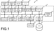
- the MFP 100 includes a control unit 110 that controls the operation of a scanner unit 101, a printer unit 102, a FAX unit 103, an I/F (interface) 104, a panel unit 105, and a HDD (Hard Disk Drive) 106.
- a control unit 110 that controls the operation of a scanner unit 101, a printer unit 102, a FAX unit 103, an I/F (interface) 104, a panel unit 105, and a HDD (Hard Disk Drive) 106.
- the HDD 106 may not be installed.
- the scanner unit 101 is a device that converts an image on a sheet of paper (not illustrated) that is read by an image sensor (not illustrated) into digital image data, and inputs the digital image data to the control unit 110.
- the printer unit 102 is a device that prints an image onto a sheet of paper (not illustrated) based on printing data outputted from the control unit 110.
- the FAX unit 103 is a device that transmits data outputted from the control unit 110 to a facsimile of another party via a telephone line and that receives data from a facsimile of another party and inputs the data to the control unit 110.
- the I/F 104 is in charge of communication with other MFPs 100, user terminals and the like via a network. Note that the I/F 104 may also be in charge of communication with a content server, a web server, or the like (not illustrated).
- the panel unit 105 is a device having a touch panel and hardware keys for performing, for example, a print function, a copy function, a FAX function, a data transmission/reception function via a network, and a display for various settings of the MFP 100.
- the HDD 106 is a storage device that stores application programs and the like for providing various functions of the MFP 100.
- the control unit 110 is a processor that executes an application program such as an authentication program or the like, an image forming program, a control program, and the like to control the overall operation of the MFP 100.
- the control unit 110 includes a scanner control unit 111, a printer control unit 112, a FAX (facsimile) control unit 113, a communication control unit 114, an EEPROM (electrically erasable and programmable read-only memory) 115, a first RAM (random access memory) 116, a second RAM 117, a memory management unit 118, an image processing unit 119, a panel operation control unit 120, an HDD control unit 121, and a system control unit 122. Moreover, these units are connected to a data bus 123. Note that the HDD control unit 121 may be omitted in a case where the MFP 100 is not equipped with the HDD 106.
- the scanner control unit 111 controls the reading operation of the scanner unit 101.
- the printer control unit 112 controls the printing operation of the printer unit 102.
- the FAX control unit 113 controls data transmission and reception operations of the FAX unit 103.
- the communication control unit 114 via the I/F 104, performs control of transmission and reception of data and the like via a network.
- the EEPROM 115 stores a control program or the like for performing an operation check or generating a startup sequence of each unit. In addition, the EEPROM 115 stores counter information and setting information.
- the counter information includes a counter value for determining a replacement time or the like of a unit part that executes a print function, a copy function, a FAX function, a data transmission/reception function via a network, and the like, a counter value such as the number of printed sheets and the like required for billing, or the like.
- the setting information includes various information that is set in the print function, the copy function, the FAX function, the data transmission/reception function via a network, and the like.
- the non-volatile memory is not limited to being an EEPROM 115, and a flash memory (registered trademark) may be used.
- the first RAM 116 (first volatile memory) and the second RAM 117 (second volatile memory) store the above-described counter information and setting information stored in the EEPROM 115 when the power to the MFP 100 is turned ON. Note that when the power to the MFP 100 is turned ON, the contents of the counter information and setting information stored in the first RAM 116 and the second RAM 117 are the same at the point in time before using the MFP 100. However, for example, the counter information and the setting information in the first RAM 116 are updated in accordance with a change in the counter value and a change in the setting contents that accompanies the use of the MFP 100. On the other hand, the counter information and setting information stored in the second RAM 117 are held without being updated.
- first RAM 116 and the second RAM 117 are work memory for executing programs.
- the work area may be increased by preferentially using the first RAM 116 as a work memory and using the second RAM 117 as a work memory when the area of the first RAM 116 becomes insufficient.
- first RAM 116 and the second RAM 117 store printing data that has undergone image processing by the image processing unit 119.
- the storage area for printing data may be increased.
- the memory management unit 118 Based on an instruction from the system control unit 122, the memory management unit 118, for example, manages the storage area in the first RAM 116 for the counter information and setting information in an updatable manner in accordance with changes in the counter value that accompanies the use of the MFP 100. In addition, the memory management unit 118 manages the storage area in the second RAM 117 for the counter information and setting information so as not to be updatable. Moreover, based on an instruction from the system control unit 122, the memory management unit 118, for example, manages the first RAM 116 so as to be preferentially usable as a work memory, and manages the second RAM 117 so as to be usable as a work memory when the area of the first RAM 116 becomes insufficient.
- the memory management unit 118 manages the first RAM 116 so as to be capable of preferentially storing printing data that has undergone image processing (rasterizing) by the image processing unit 119, and manages the second RAM 117 so as to be capable of storing printing data that has undergone image processing (rasterizing) by the image processing unit 119 when the area of the first RAM 116 becomes insufficient.
- the memory management unit 118 may reverse the management of the first RAM 116 and the second RAM 117.
- the memory management unit 118 may manage the storage area in the second RAM 117 for the counter information and the setting information so as to be updatable, and manage the storage area in the first RAM 116 for the counter information and the setting information so as not to be updatable.
- the memory management unit 118 may manage the second RAM 117 so as to be preferentially usable as a work memory, and manage the first RAM 116 so as to be usable as a work memory when the area of the second RAM 117 becomes insufficient.
- the memory management unit 118 may manage the second RAM 117 so as to be capable of preferentially storing printing data that has undergone image processing (rasterizing) by the image processing unit 119, and manage the first RAM 116 so as to be capable storing printing data that has undergone image processing (rasterizing) by the image processing unit 119 when the area of the second RAM 117 becomes insufficient.
- the image processing unit 119 performs image processing (rasterizing) on the image data read by the scanner unit 101. In addition, the image processing unit 119 performs image processing (rasterizing) on printing jobs registered in a user box of the HDD 106 or printing data in a page description language (PDL: Page Description Language). Note that the system control unit 122 temporarily stores printing data that has undergone image processing by the image processing unit 119 in the first RAM 116 or the second RAM 117.
- the panel operation control unit 120 controls the display operation of the panel unit 105.
- the panel operation control unit 120 via the panel unit 105, receives settings for printing, copying, faxing, data transmission/reception via a network, and the like.
- the panel operation control unit 120 via the panel unit 105, receives an operation for turning ON/OFF the power to the MFP 100.
- the panel operation control unit 120 may receive an operation for turning the power ON or OFF by a touch operation of either one of the buttons.
- the power-ON button and the power-OFF button displayed by the panel unit 105 may be one power button.
- the panel operation control unit 120 alternately receives power ON and power OFF each time the power button is touch-operated.
- turning ON the power means, for example, returning from the power-OFF mode to the power-ON mode.
- turning OFF the power means, for example, returning from the power-ON mode to the power-OFF mode.
- the process of returning from the power-OFF mode to the power-ON mode and the process of returning from the power-ON mode to the power-OFF mode are executed by the system control unit 122 controlling a power control unit (not illustrated).
- the HDD control unit 121 controls reading data from and writing data to the HDD 106 and the like.
- the system control unit 122 controls cooperative operation and the like of each unit.
- the system control unit 122 reads the counter information and setting information described above from the EEPROM 115 and writes the information in the first RAM 116 and the second RAM 117.
- the system control unit 122 may execute either of the two methods illustrated in FIGS. 2A and 2B .
- the system control unit 122 for example, may execute a method of simultaneously writing the counter information and the setting information read from the EEPROM 115 to the first RAM 116 and the second RAM 117 as illustrated in FIG. 2A .
- the system control unit 122 may directly write the counter information and the setting information read from the EEPROM 115 to the first RAM 116 and the second RAM 117.
- the counter information and setting information read from the EEPROM 115 may be written to the first RAM 116 and the second RAM 117 at one time, so the time until the startup of the MFP 100 is completed may be shortened.
- the first RAM 116 and the second RAM 117 have short data read/write times. Therefore, the system control unit 122 may execute writing of the counter information and the setting information to the first RAM 116 and the second RAM 117 in a short time.
- startup of the MFP 100 means that a program for initializing each functional unit is executed in accordance with the startup sequence.
- the system control unit 122 may execute a method of writing counter information and setting information read from the EEPROM 115 to the first RAM 116 beforehand, reading counter information and setting information from the first RAM 116, and writing that information to the second RAM 117.
- the system control unit 122 may directly write the counter information and the setting information read from the EEPROM 115 to the first RAM 116, and indirectly write the information to the second RAM 117.
- the writing process according to the methods illustrated in FIGS. 2A and 2B are executed in the startup sequence of the MFP 100 or in parallel with the startup sequence.
- the system control unit 122 enables use of the MFP 100.
- the system control unit 122 reads and compares the counter information and setting information stored in the first RAM 116 with the counter information and setting information stored in the second RAM 117, and only writes the different data to the EEPROM 115.
- the first RAM 116 and the second RAM 117 have short data read/write times. Therefore, since the read time of the counter information and the setting information from the first RAM 116 and the second RAM 117 executed when the system control unit 122 compares the counter information and the setting information is short, the comparison of the counter information and the setting information from both is also performed in a short time. Moreover, of the counter information and the setting information from both, the system control unit 122 writes only the different data to the EEPROM 115, so the transition time to the power-OFF mode when the power of the MFP 100 is turned OFF may be shortened.
- the system control unit 122 determines whether or not the power is turned ON.
- the system control unit 122 determines that the power is not turned ON unless there is a notification from the panel operation control unit 120 via the panel unit 105 indicating that the power-ON button has been touch-operated (step S101: NO).
- step S101 determines that the power is turned ON (step S101: YES), and the process moves to step S102.
- the system control unit 122 instructs transition to the power-ON mode.
- system control unit 122 instructs the power control unit (not illustrated) to transition to the power-ON mode.
- the system control unit 122 reads the counter information and the setting information.
- the system control unit 122 reads the counter information and the setting information from the EEPROM 115.
- the system control unit 122 writes the counter information and the setting information.
- the system control unit 122 writes the counter information and the setting information read from the EEPROM 115 to the first RAM 116 and the second RAM 117.
- the system control unit 122 instructs the memory management unit 118 to perform memory management.
- the memory management unit 118 manages the storage area in the first RAM 116 for the counter information and setting information so as to be updatable in accordance with changes in the counter value and changes in the setting contents that accompanies the use of the MFP 100.
- the memory management unit 118 manages the storage area in the second RAM 117 for the counter information and setting information so as not to be updatable.
- the memory management unit 118 for example, manages the first RAM 116 so as to be preferentially usable as a work memory, and manages the second RAM 117 so as to be usable as a work memory when the area of the first RAM 116 becomes insufficient.
- the memory management unit 118 manages the first RAM 116 so as to be capable of preferentially storing printing data that has undergone image processing (rasterizing) by the image processing unit 119, and manages the second RAM 117 so as to be capable of storing printing data that has undergone image processing (rasterizing) by the image processing unit 119 when the area of the first RAM 116 becomes insufficient.
- the system control unit 122 determines whether or not there is a change in the counter information.
- the system control unit 122 determines that there is no change in the counter information when the counter value corresponding to any one of the print function, the copy function, the FAX function, and the data transmission/reception function via a network does not change (step S106: NO), then processing moves to step S108.
- step S106 determines that there is change in the counter information when the counter value corresponding to any one of the print function, the copy function, the FAX function, and the data transmission/reception function via a network changes (step S106: YES), then processing moves to step S107.
- the system control unit 122 rewrites the counter information.
- the system control unit 122 confirms that the memory management unit 118 is managing the storage area in the first RAM 116 for the counter information so as to be updatable, and rewrites the counter information in the first RAM 116 based on the counter value corresponding to any one of the print function, the copy function, the FAX function, and the data transmission/reception function via a network.
- the system control unit 122 determines whether or not there is a change in the setting information.
- step S108 NO
- processing moves to step S110.
- step S108 the system control unit 122 determines that there is a change in the setting information when there is a notification from the panel operation control unit 120 via the panel unit 105 indicating that there is an operation to change the setting for any one of the print function, the copy function, the FAX function, and the data transmission/reception function via a network (step S108: YES), then processing moves to step S109.
- the system control unit 122 rewrites the setting information.
- the system control unit 122 confirms that the memory management unit 118 is managing the storage area in the first RAM 116 for the counter information so as to be updatable, and rewrites the setting information in the first RAM 116 based on the setting contents corresponding to any one of the print function, the copy function, the FAX function, and the data transmission/reception function via a network.
- the system control unit 122 determines whether or not the power is turned OFF.
- step S110 NO
- processing returns to step S106.
- step S110 determines that the power is turned OFF when there is a notification from the panel operation control unit 120 via the panel unit 105 indicating that the power-OFF button has been touch-operated (step S110: YES), then processing moves to step S111.
- the system control unit 122 reads the counter information and the setting information.
- the system control unit 122 reads the counter information and the setting information from the first RAM 116 and the second RAM 117.
- the system control unit 122 compares the counter information and the setting information.
- the system control unit 122 compares the counter information and setting information read from the first RAM 116 with the counter information and setting information read from the second RAM 117.
- the system control unit 122 determines whether or not there is data that is different.
- the counter information and setting information in the second RAM 117 are managed by the memory management unit 118 so as not to be updatable, so the contents are the same as the counter information and setting information stored in the EEPROM 115.
- the counter information and setting information in the first RAM 116 are managed by the memory management unit 118 so as to be updatable, so the contents are changed in accordance with changes in the counter value and changes in the setting contents.
- the system control unit 122 compares the counter information and setting information read from the first RAM 116 with the counter information and setting information read from the second RAM 117 for each storage unit (for example, for each 1 byte), and in a case where a difference in data cannot be confirmed, determines that there is no data that is different (step S113: NO), and the process moves to step S115.
- the system control unit 122 compares the counter information and setting information read from the first RAM 116 with the counter information and setting information read from the second RAM 117, and in a case where a difference in data can be confirmed, determines that there is data that is different (step S113: YES), and the process moves to step S114.
- the system control unit 122 writes the data that is different.
- the system control unit 122 writes only different data to the EEPROM 115. More specifically, the system control unit 122 writes the different data read from the first RAM 116 to the EEPROM 115 and does not write the same data to the EEPROM 115.
- the system control unit 122 instructs transition to the power-OFF mode.
- system control unit 122 instructs the power control unit (not illustrated) to transition to the power-OFF mode.
- the EEPROM 115 stores counter information and setting information (apparatus use related information) related to the use of MFP 100 (apparatus)
- the first RAM 116 (first volatile memory) stores counter information and setting information (apparatus use related information)
- the second RAM 117 (second volatile memory) stores counter information and setting information (apparatus use related information)
- the memory management unit 118 manages a storage area in the first RAM 116 (first volatile memory) for the counter information and setting information (apparatus use related information) so as to be updatable and manages a storage area in the second RAM 117 (second volatile memory) for the counter information and setting information (apparatus use related information) so as not to be updatable
- the system control unit 122 writes counter information and setting information (apparatus use related information) read from the EEPROM 115 (non-volatile memory) to the first RAM 116 (first volatile memory) and the second RAM 117 (second volatile memory) in accordance with turning the power ON
- the system control unit when there is a change in the contents of the counter information and setting information (apparatus use related information), the system control unit rewrites the counter information and setting information (apparatus use related information) in the first RAM 116 (first volatile memory) in accordance to the changed contents, and when the power is turned OFF, the system control unit reads and compares the counter information and setting information (apparatus use related information) in the first RAM 116 (first volatile memory) with the counter information and setting information (apparatus use related information) in the second RAM 116 (second volatile memory), and writes only the different information to the EEPROM 115 (non-volatile memory).
- the first RAM 116 (first volatile memory) and the second RAM 117 (second volatile memory) have shorter information read/write times than the EEPROM 115 (non-volatile memory). Therefore, when the power is turned OFF, the system control unit 122 may perform reading and comparison of the counter information and setting information (apparatus use related information) in the first RAM 116 (first volatile memory) and the counter information and setting information (apparatus use related information) in the second RAM 116 (second volatile memory) in a short time.
- the system control unit 122 writes only the different information to the EEPROM 115 (non-volatile memory), so the number of times of writing information to the EEPROM 115 (non-volatile memory) may be reduced, and the amount of information written to the EEPROM 115 (non-volatile memory) may be reduced.
- writing of the counter information and the setting information (apparatus use related information) to the first RAM 116 (first volatile memory) and the second RAM 117 (second volatile memory) and comparison of the counter information and the setting information (apparatus use related information) in the first RAM 116 (first volatile memory) with the counter information and the setting information (apparatus use related information) in the second RAM 117 (second volatile memory) by the system control unit 122 may be performed in a short time, and in addition, the number times of writing information to the EEPROM 115 (non-volatile memory) may be reduce, as well as the amount of information written to the EEPROM 115 (non-volatile memory) may be reduced, so the life of the non-volatile memory may be extended without increasing the processing time due to turning the power ON/OFF.
- the system control unit 122 may also execute a method of writing the counter information and the setting information read from the EEPROM 115 to the first RAM 116 beforehand, and then after startup of the MFP 100 is completed, reading the counter information and the setting information from the EEPROM 115 in a background process and writing the information in the second RAM 117.
- the counter information and setting information read from the EEPROM 115 may first be written to the first RAM 116, so the time until the startup of the MFP 100 is completed may be shortened.
- the system control unit 122 enables the use of the MFP 100.
- first RAM 116 and the second RAM 117 may each be a separate memory module.
- first RAM 116 and the second RAM 117 may be provided in one memory module as one or a plurality of memory chips.
- first RAM 116 and the second RAM 117 may each be one or a plurality of memory chips.
- the first RAM 116 and the second RAM 117 may be one or a plurality of memory chips in common, and the storage areas for the respective first RAM 116 and the second RAM 117 may be allocated to one or a plurality of memory chips.
- the apparatus use related information is not limited to the counter information and the setting information, and may be only the setting information.
- the MFP 100 is used as an example of an electronic apparatus, however the present invention may be applied to other electronic apparatuses such as a multi-function printer, a PC (Personal Computer), and the like.
Abstract
Description
- The present invention relates to a memory system and an electronic apparatus in which use of a non-volatile memory is suitable.
- For example, an image forming apparatus such as an MFP (Multifunction Peripheral) and the like, which is one kind of electronic apparatus, is equipped with various consumable parts. In a case where a print function, a copy function, a FAX function, a data transmission/reception function via a network, and the like are installed, unit parts that execute these respective functions correspond as consumable parts. Moreover, a rewritable non-volatile memory, a volatile memory used as a work memory for executing a program, and the like also correspond as consumable parts. Note that, in a non-volatile memory, counter information for determining the replacement time or the like of each unit part, setting information related to each function, and the like are stored.
- Incidentally, in an image forming apparatus, when the power is turned ON, the above-described setting information, counter information, and the like stored in the non-volatile memory are read from the non-volatile memory and expanded in the volatile memory. Moreover, in the power-ON state, when the above-described counter information is changed or the settings of the various functions are changed, the changed contents are stored in the volatile memory. Then, when the power of the image forming apparatus is turned OFF, the changed contents stored in the volatile memory are written to the non-volatile memory. As a result, when the power to the image forming apparatus is turned ON again, the previous counter information and setting information are taken over.
- As described above, the changed contents stored in the volatile memory are written to the non-volatile memory each time the image forming apparatus is switched from power ON to power OFF. Therefore, when the power to the image forming apparatus is frequently switched between ON and OFF, the number of times that the changed contents are written to the non-volatile memory is increased, and the life of the non-volatile memory is shortened.
- In order to solve such a problem, Patent Literature 1 proposes a control apparatus for automobiles that, when the key switch is turned OFF, only writes data to the non-volatile memory in a case where the contents of the volatile memory and the contents of the non-volatile memory are compared, and there is a difference between the data of both.
- Patent Literature 1:
JP H11-141391 A - In the control apparatus for an automobile of Patent Literature 1 described above, the writing of data to the non-volatile memory is performed only when there is a difference between the contents of the volatile memory and the contents of the non-volatile memory, so the number of times that writing is performed may be reduced.
- Incidentally, in the non-volatile memory and the volatile memory, the respective structures and the like are different, so the methods of reading and writing the respective data are different. Moreover, in general, the speed of reading and writing data in a non-volatile memory is slower than the speed of reading and writing data in a volatile memory.
- Therefore, when comparing the contents of non-volatile memory and the contents of volatile memory in accordance to turning OFF the key switch as in the control apparatus for an automobile of Patent Literature 1, reading of data from the non-volatile memory is slower than reading of data from the volatile memory, so there is a possibility that the time from the reading of the data to the completion of the writing of the different data to the non-volatile memory may become long.
- Taking into consideration such a situation, an object of the present invention is to provide a memory system and an electronic apparatus capable of solving the problems described above.
- The memory system according to the present invention includes: a non-volatile memory; a first volatile memory in which apparatus use related information stored in the non-volatile memory and that is related to use of an apparatus is written; a second volatile memory in which the apparatus use related information stored in the non-volatile memory is written; a memory management unit that manages a storage area for the apparatus use related information written in the first volatile memory so as to be updatable, and manages a storage area for the apparatus use related information written in the second volatile memory so as not to be updatable; and a system control unit that writes the apparatus use related information read from the non-volatile memory to the first volatile memory and the second volatile memory in accordance with turning power ON; wherein the system control unit, when a change in contents of the apparatus use related information occurs, rewrites the apparatus use related information in the first volatile memory according to the changed contents; and when the power is turned OFF, reads and compares the apparatus use related information in the first volatile memory with the apparatus use related information in the second volatile memory, and only writes different data to the non-volatile memory.
- The electronic apparatus according to the present invention includes: a non-volatile memory; a first volatile memory in which apparatus use related information stored in the non-volatile memory and that is related to use of an apparatus is written; a second volatile memory in which the apparatus use related information stored in the non-volatile memory is written; a memory management unit that manages a storage area for the apparatus use related information written in the first volatile memory so as to be updatable, and manages a storage area for the apparatus use related information written in the second volatile memory so as not to be updatable; and a system control unit that writes the apparatus use related information read from the non-volatile memory to the first volatile memory and the second volatile memory in accordance with turning power ON; wherein the system control unit, when a change in contents of the apparatus use related information occurs, rewrites the apparatus use related information in the first volatile memory according to the changed contents; and when the power is turned OFF, reads and compares the apparatus use related information in the first volatile memory with the apparatus use related information in the second volatile memory, and only writes different data to the non-volatile memory.
- In the memory system and electronic apparatus according to the present invention, the non-volatile memory stores apparatus use related information related to use of an apparatus, the first volatile memory stores apparatus use related information, the second volatile memory stores apparatus use related information, the memory management unit manages a storage area in the first volatile memory for the apparatus use related information so as to be updatable and manages a storage area in the second volatile memory for the apparatus use related information so as not to be updatable, and the system control unit, when the power is turned ON, writes the apparatus use related information read from the non-volatile memory to the first volatile memory and the second volatile memory. Moreover, the system control unit, when a change in the contents of the apparatus use related information occurs, rewrites the apparatus use related information in the first volatile memory in accordance to the changed contents, and when the power is turned OFF, reads and compares the apparatus use related information in the first volatile memory with the apparatus use related information in the second volatile memory, and writes only the different information to the non-volatile memory.
- Here, the first volatile memory and the second volatile memory have shorter information read/write times than the non-volatile memory. Therefore, when the power is turned OFF, the system control unit may perform reading and comparison of the apparatus use related information in the first volatile memory and the apparatus use related information in the second volatile memory in a short time. In addition, when the power is turned OFF, the system control unit writes only the different information to the non-volatile memory, so the number of times of writing information to the non-volatile memory may be reduced, and the amount of information written to the non-volatile memory may be reduced.
- With the memory system and the electronic apparatus according to the present invention, comparison of the apparatus use related information in the first volatile memory and the apparatus use related information in the second volatile memory by the system control unit may be performed in a short time, as well as the number of times of writing information to the non-volatile memory may be reduced and the amount of information written to the non-volatile memory may be reduced, so the life of the non-volatile memory may be extended without increasing the processing time due to turning the power ON/OFF.
-
-
FIG. 1 is a diagram for explaining an embodiment in a case where an electronic apparatus according to the present invention is applied to an MFP. -
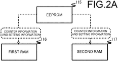
FIG. 2A is a diagram for describing a method of writing counter information and setting information of an EEPROM by the system control unit inFIG. 1 , and illustrates an example of a case of writing counter information and setting information simultaneously to a first RAM and a second RAM. -
FIG. 2B is a diagram for describing a method of writing counter information and setting information of an EEPROM by the system control unit inFIG. 1 , and illustrates an example of a case of writing counter information and setting information to a first RAM, and then writing the counter information and setting information written to the first RAM to asecond RAM 117. -
FIG. 3 is a flowchart for describing a process related to reading and writing of counter information and setting information to and from the EEPROM in accordance with turning the power ON/OFF to the MFP inFIG. 1 . - In the following, an embodiment of an electronic apparatus according to the present invention will be described with reference to
FIGS. 1 to 3 . Note that as an example of the electronic apparatus in the following description is an MFP (Multifunction Peripheral) which is a complex peripheral apparatus equipped, for example, with a print function, a copy function, a FAX function, a data transmission/reception function via a network, and the like. - First, as illustrated in
FIG. 1 , the MFP 100 includes acontrol unit 110 that controls the operation of ascanner unit 101, aprinter unit 102, aFAX unit 103, an I/F (interface) 104, apanel unit 105, and a HDD (Hard Disk Drive) 106. Note that although a case is presumed in which theMFP 100 according to this embodiment is installed with theHDD 106, theHDD 106 may not be installed. - The
scanner unit 101 is a device that converts an image on a sheet of paper (not illustrated) that is read by an image sensor (not illustrated) into digital image data, and inputs the digital image data to thecontrol unit 110. Theprinter unit 102 is a device that prints an image onto a sheet of paper (not illustrated) based on printing data outputted from thecontrol unit 110. TheFAX unit 103 is a device that transmits data outputted from thecontrol unit 110 to a facsimile of another party via a telephone line and that receives data from a facsimile of another party and inputs the data to thecontrol unit 110. - The I/F 104 is in charge of communication with
other MFPs 100, user terminals and the like via a network. Note that the I/F 104 may also be in charge of communication with a content server, a web server, or the like (not illustrated). Thepanel unit 105 is a device having a touch panel and hardware keys for performing, for example, a print function, a copy function, a FAX function, a data transmission/reception function via a network, and a display for various settings of theMFP 100. The HDD 106 is a storage device that stores application programs and the like for providing various functions of theMFP 100. - The
control unit 110 is a processor that executes an application program such as an authentication program or the like, an image forming program, a control program, and the like to control the overall operation of the MFP 100. Thecontrol unit 110 includes ascanner control unit 111, aprinter control unit 112, a FAX (facsimile)control unit 113, acommunication control unit 114, an EEPROM (electrically erasable and programmable read-only memory) 115, a first RAM (random access memory) 116, asecond RAM 117, amemory management unit 118, animage processing unit 119, a paneloperation control unit 120, anHDD control unit 121, and asystem control unit 122. Moreover, these units are connected to adata bus 123. Note that theHDD control unit 121 may be omitted in a case where the MFP 100 is not equipped with theHDD 106. - The
scanner control unit 111 controls the reading operation of thescanner unit 101. Theprinter control unit 112 controls the printing operation of theprinter unit 102. TheFAX control unit 113 controls data transmission and reception operations of theFAX unit 103. Thecommunication control unit 114, via the I/F 104, performs control of transmission and reception of data and the like via a network. The EEPROM 115 stores a control program or the like for performing an operation check or generating a startup sequence of each unit. In addition, the EEPROM 115 stores counter information and setting information. Here, the counter information includes a counter value for determining a replacement time or the like of a unit part that executes a print function, a copy function, a FAX function, a data transmission/reception function via a network, and the like, a counter value such as the number of printed sheets and the like required for billing, or the like. The setting information includes various information that is set in the print function, the copy function, the FAX function, the data transmission/reception function via a network, and the like. Incidentally, the non-volatile memory is not limited to being anEEPROM 115, and a flash memory (registered trademark) may be used. - The first RAM 116 (first volatile memory) and the second RAM 117 (second volatile memory) store the above-described counter information and setting information stored in the
EEPROM 115 when the power to theMFP 100 is turned ON. Note that when the power to theMFP 100 is turned ON, the contents of the counter information and setting information stored in thefirst RAM 116 and thesecond RAM 117 are the same at the point in time before using theMFP 100. However, for example, the counter information and the setting information in thefirst RAM 116 are updated in accordance with a change in the counter value and a change in the setting contents that accompanies the use of theMFP 100. On the other hand, the counter information and setting information stored in thesecond RAM 117 are held without being updated. - In addition, the
first RAM 116 and thesecond RAM 117 are work memory for executing programs. In this case, for example, the work area may be increased by preferentially using thefirst RAM 116 as a work memory and using thesecond RAM 117 as a work memory when the area of thefirst RAM 116 becomes insufficient. In addition thefirst RAM 116 and thesecond RAM 117 store printing data that has undergone image processing by theimage processing unit 119. In this case, for example, by preferentially using thefirst RAM 116 for storing printing data that has undergone image processing (rasterizing) by theimage processing unit 119, and using thesecond RAM 117 to store printing data that has undergone image processing (rasterizing) by theimage processing unit 119 when the area in thefirst RAM 116 becomes insufficient, the storage area for printing data may be increased. - Based on an instruction from the
system control unit 122, thememory management unit 118, for example, manages the storage area in thefirst RAM 116 for the counter information and setting information in an updatable manner in accordance with changes in the counter value that accompanies the use of theMFP 100. In addition, thememory management unit 118 manages the storage area in thesecond RAM 117 for the counter information and setting information so as not to be updatable. Moreover, based on an instruction from thesystem control unit 122, thememory management unit 118, for example, manages thefirst RAM 116 so as to be preferentially usable as a work memory, and manages thesecond RAM 117 so as to be usable as a work memory when the area of thefirst RAM 116 becomes insufficient. Furthermore, thememory management unit 118, for example, manages thefirst RAM 116 so as to be capable of preferentially storing printing data that has undergone image processing (rasterizing) by theimage processing unit 119, and manages thesecond RAM 117 so as to be capable of storing printing data that has undergone image processing (rasterizing) by theimage processing unit 119 when the area of thefirst RAM 116 becomes insufficient. - Incidentally, the
memory management unit 118 may reverse the management of thefirst RAM 116 and thesecond RAM 117. In other words, thememory management unit 118 may manage the storage area in thesecond RAM 117 for the counter information and the setting information so as to be updatable, and manage the storage area in thefirst RAM 116 for the counter information and the setting information so as not to be updatable. Moreover, thememory management unit 118 may manage thesecond RAM 117 so as to be preferentially usable as a work memory, and manage thefirst RAM 116 so as to be usable as a work memory when the area of thesecond RAM 117 becomes insufficient. Furthermore, thememory management unit 118 may manage thesecond RAM 117 so as to be capable of preferentially storing printing data that has undergone image processing (rasterizing) by theimage processing unit 119, and manage thefirst RAM 116 so as to be capable storing printing data that has undergone image processing (rasterizing) by theimage processing unit 119 when the area of thesecond RAM 117 becomes insufficient. - The
image processing unit 119 performs image processing (rasterizing) on the image data read by thescanner unit 101. In addition, theimage processing unit 119 performs image processing (rasterizing) on printing jobs registered in a user box of theHDD 106 or printing data in a page description language (PDL: Page Description Language). Note that thesystem control unit 122 temporarily stores printing data that has undergone image processing by theimage processing unit 119 in thefirst RAM 116 or thesecond RAM 117. - The panel
operation control unit 120 controls the display operation of thepanel unit 105. In addition, the paneloperation control unit 120, via thepanel unit 105, receives settings for printing, copying, faxing, data transmission/reception via a network, and the like. Moreover, the paneloperation control unit 120, via thepanel unit 105, receives an operation for turning ON/OFF the power to theMFP 100. In this case, by causing thepanel unit 105 to display a power-ON button and a power-OFF button, the paneloperation control unit 120 may receive an operation for turning the power ON or OFF by a touch operation of either one of the buttons. Here, the power-ON button and the power-OFF button displayed by thepanel unit 105 may be one power button. In this case, the paneloperation control unit 120 alternately receives power ON and power OFF each time the power button is touch-operated. Note that turning ON the power means, for example, returning from the power-OFF mode to the power-ON mode. Moreover, turning OFF the power means, for example, returning from the power-ON mode to the power-OFF mode. Furthermore, the process of returning from the power-OFF mode to the power-ON mode and the process of returning from the power-ON mode to the power-OFF mode are executed by thesystem control unit 122 controlling a power control unit (not illustrated). TheHDD control unit 121 controls reading data from and writing data to theHDD 106 and the like. - The
system control unit 122 controls cooperative operation and the like of each unit. In addition, when the power of theMFP 100 is turned ON, thesystem control unit 122 reads the counter information and setting information described above from theEEPROM 115 and writes the information in thefirst RAM 116 and thesecond RAM 117. Here, when writing the counter information and setting information read from theEEPROM 115 to thefirst RAM 116 and thesecond RAM 117, thesystem control unit 122 may execute either of the two methods illustrated inFIGS. 2A and2B . First, thesystem control unit 122, for example, may execute a method of simultaneously writing the counter information and the setting information read from theEEPROM 115 to thefirst RAM 116 and thesecond RAM 117 as illustrated inFIG. 2A . In other words, thesystem control unit 122 may directly write the counter information and the setting information read from theEEPROM 115 to thefirst RAM 116 and thesecond RAM 117. In this method, the counter information and setting information read from theEEPROM 115 may be written to thefirst RAM 116 and thesecond RAM 117 at one time, so the time until the startup of theMFP 100 is completed may be shortened. In other words, thefirst RAM 116 and thesecond RAM 117 have short data read/write times. Therefore, thesystem control unit 122 may execute writing of the counter information and the setting information to thefirst RAM 116 and thesecond RAM 117 in a short time. Incidentally, startup of theMFP 100 means that a program for initializing each functional unit is executed in accordance with the startup sequence. - Moreover, the
system control unit 122, for example, as illustrated inFIG. 2B , may execute a method of writing counter information and setting information read from theEEPROM 115 to thefirst RAM 116 beforehand, reading counter information and setting information from thefirst RAM 116, and writing that information to thesecond RAM 117. In other words, thesystem control unit 122 may directly write the counter information and the setting information read from theEEPROM 115 to thefirst RAM 116, and indirectly write the information to thesecond RAM 117. - Incidentally, the writing process according to the methods illustrated in
FIGS. 2A and2B are executed in the startup sequence of theMFP 100 or in parallel with the startup sequence. In addition, when the startup of theMFP 100 is completed and the writing of the counter information and the setting information to thefirst RAM 116 and thesecond RAM 117 is completed, thesystem control unit 122 enables use of theMFP 100. - Furthermore, when the power to the
MFP 100 is turned OFF, thesystem control unit 122 reads and compares the counter information and setting information stored in thefirst RAM 116 with the counter information and setting information stored in thesecond RAM 117, and only writes the different data to theEEPROM 115. Here, as described above, thefirst RAM 116 and thesecond RAM 117 have short data read/write times. Therefore, since the read time of the counter information and the setting information from thefirst RAM 116 and thesecond RAM 117 executed when thesystem control unit 122 compares the counter information and the setting information is short, the comparison of the counter information and the setting information from both is also performed in a short time. Moreover, of the counter information and the setting information from both, thesystem control unit 122 writes only the different data to theEEPROM 115, so the transition time to the power-OFF mode when the power of theMFP 100 is turned OFF may be shortened. - Next, a process related to reading and writing counter information and setting information to and from the
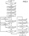
EEPROM 115 when the power of theMFP 100 is turned ON/OFF will be described with reference toFIG. 3 . Note that in the following, a case as illustrated inFIG. 2A for example in which thesystem control unit 122 simultaneously writes the counter information and the setting information read from theEEPROM 115 to thefirst RAM 116 and thesecond RAM 117 will be described. Moreover, turning the power to theMFP 100 ON/OFF as described below is performed via thepanel unit 105. - The
system control unit 122 determines whether or not the power is turned ON. - In this case, the
system control unit 122 determines that the power is not turned ON unless there is a notification from the paneloperation control unit 120 via thepanel unit 105 indicating that the power-ON button has been touch-operated (step S101: NO). - On the other hand, when there is a notification from panel
operation control unit 120 viapanel unit 105 indicating that the power-ON button is touch-operated, thesystem control unit 122 determines that the power is turned ON (step S101: YES), and the process moves to step S102. - The
system control unit 122 instructs transition to the power-ON mode. - In this case, the
system control unit 122 instructs the power control unit (not illustrated) to transition to the power-ON mode. - The
system control unit 122 reads the counter information and the setting information. - In this case, the
system control unit 122 reads the counter information and the setting information from theEEPROM 115. - The
system control unit 122 writes the counter information and the setting information. - In this case, the
system control unit 122 writes the counter information and the setting information read from theEEPROM 115 to thefirst RAM 116 and thesecond RAM 117. - The
system control unit 122 instructs thememory management unit 118 to perform memory management. - At this time, the
memory management unit 118, for example, manages the storage area in thefirst RAM 116 for the counter information and setting information so as to be updatable in accordance with changes in the counter value and changes in the setting contents that accompanies the use of theMFP 100. In addition, thememory management unit 118 manages the storage area in thesecond RAM 117 for the counter information and setting information so as not to be updatable. Moreover, thememory management unit 118, for example, manages thefirst RAM 116 so as to be preferentially usable as a work memory, and manages thesecond RAM 117 so as to be usable as a work memory when the area of thefirst RAM 116 becomes insufficient. Furthermore, thememory management unit 118, for example, manages thefirst RAM 116 so as to be capable of preferentially storing printing data that has undergone image processing (rasterizing) by theimage processing unit 119, and manages thesecond RAM 117 so as to be capable of storing printing data that has undergone image processing (rasterizing) by theimage processing unit 119 when the area of thefirst RAM 116 becomes insufficient. - The
system control unit 122 determines whether or not there is a change in the counter information. - In this case, the
system control unit 122, for example, determines that there is no change in the counter information when the counter value corresponding to any one of the print function, the copy function, the FAX function, and the data transmission/reception function via a network does not change (step S106: NO), then processing moves to step S108. - On the other hand, the
system control unit 122 determines that there is change in the counter information when the counter value corresponding to any one of the print function, the copy function, the FAX function, and the data transmission/reception function via a network changes (step S106: YES), then processing moves to step S107. - The
system control unit 122 rewrites the counter information. - In this case, the
system control unit 122 confirms that thememory management unit 118 is managing the storage area in thefirst RAM 116 for the counter information so as to be updatable, and rewrites the counter information in thefirst RAM 116 based on the counter value corresponding to any one of the print function, the copy function, the FAX function, and the data transmission/reception function via a network. - The
system control unit 122 determines whether or not there is a change in the setting information. - In this case, the
system control unit 122 determines that there is no change in the setting information when there is no notification from the paneloperation control unit 120 via thepanel unit 105 indicating that there is an operation to change the setting for any one of the print function, the copy function, the FAX function, and the data transmission/reception function via a network (step S108: NO), then processing moves to step S110. - On the other hand, the
system control unit 122 determines that there is a change in the setting information when there is a notification from the paneloperation control unit 120 via thepanel unit 105 indicating that there is an operation to change the setting for any one of the print function, the copy function, the FAX function, and the data transmission/reception function via a network (step S108: YES), then processing moves to step S109. - The
system control unit 122 rewrites the setting information. - In this case, the
system control unit 122 confirms that thememory management unit 118 is managing the storage area in thefirst RAM 116 for the counter information so as to be updatable, and rewrites the setting information in thefirst RAM 116 based on the setting contents corresponding to any one of the print function, the copy function, the FAX function, and the data transmission/reception function via a network. - The
system control unit 122 determines whether or not the power is turned OFF. - In this case, the
system control unit 122 determines that the power is not turned OFF unless there is a notification from the paneloperation control unit 120 via thepanel unit 105 indicating that the power-OFF button has been touch-operated (step S110: NO), then processing returns to step S106. - On the other hand, the
system control unit 122 determines that the power is turned OFF when there is a notification from the paneloperation control unit 120 via thepanel unit 105 indicating that the power-OFF button has been touch-operated (step S110: YES), then processing moves to step S111. - The
system control unit 122 reads the counter information and the setting information. - In this case, the
system control unit 122 reads the counter information and the setting information from thefirst RAM 116 and thesecond RAM 117. - The
system control unit 122 compares the counter information and the setting information. - In this case, the
system control unit 122 compares the counter information and setting information read from thefirst RAM 116 with the counter information and setting information read from thesecond RAM 117. - The
system control unit 122 determines whether or not there is data that is different. - Here, the counter information and setting information in the
second RAM 117 are managed by thememory management unit 118 so as not to be updatable, so the contents are the same as the counter information and setting information stored in theEEPROM 115. On the other hand, the counter information and setting information in thefirst RAM 116 are managed by thememory management unit 118 so as to be updatable, so the contents are changed in accordance with changes in the counter value and changes in the setting contents. - The
system control unit 122 compares the counter information and setting information read from thefirst RAM 116 with the counter information and setting information read from thesecond RAM 117 for each storage unit (for example, for each 1 byte), and in a case where a difference in data cannot be confirmed, determines that there is no data that is different (step S113: NO), and the process moves to step S115. - On the other hand, the
system control unit 122 compares the counter information and setting information read from thefirst RAM 116 with the counter information and setting information read from thesecond RAM 117, and in a case where a difference in data can be confirmed, determines that there is data that is different (step S113: YES), and the process moves to step S114. - The
system control unit 122 writes the data that is different. - In this case, the
system control unit 122 writes only different data to theEEPROM 115. More specifically, thesystem control unit 122 writes the different data read from thefirst RAM 116 to theEEPROM 115 and does not write the same data to theEEPROM 115. - The
system control unit 122 instructs transition to the power-OFF mode. - In this case, the
system control unit 122 instructs the power control unit (not illustrated) to transition to the power-OFF mode. - In this way, in this embodiment, the EEPROM 115 (non-volatile memory) stores counter information and setting information (apparatus use related information) related to the use of MFP 100 (apparatus), the first RAM 116 (first volatile memory) stores counter information and setting information (apparatus use related information), the second RAM 117 (second volatile memory) stores counter information and setting information (apparatus use related information), the
memory management unit 118 manages a storage area in the first RAM 116 (first volatile memory) for the counter information and setting information (apparatus use related information) so as to be updatable and manages a storage area in the second RAM 117 (second volatile memory) for the counter information and setting information (apparatus use related information) so as not to be updatable, and thesystem control unit 122 writes counter information and setting information (apparatus use related information) read from the EEPROM 115 (non-volatile memory) to the first RAM 116 (first volatile memory) and the second RAM 117 (second volatile memory) in accordance with turning the power ON. In addition, when there is a change in the contents of the counter information and setting information (apparatus use related information), the system control unit rewrites the counter information and setting information (apparatus use related information) in the first RAM 116 (first volatile memory) in accordance to the changed contents, and when the power is turned OFF, the system control unit reads and compares the counter information and setting information (apparatus use related information) in the first RAM 116 (first volatile memory) with the counter information and setting information (apparatus use related information) in the second RAM 116 (second volatile memory), and writes only the different information to the EEPROM 115 (non-volatile memory). - Here, the first RAM 116 (first volatile memory) and the second RAM 117 (second volatile memory) have shorter information read/write times than the EEPROM 115 (non-volatile memory). Therefore, when the power is turned OFF, the
system control unit 122 may perform reading and comparison of the counter information and setting information (apparatus use related information) in the first RAM 116 (first volatile memory) and the counter information and setting information (apparatus use related information) in the second RAM 116 (second volatile memory) in a short time. In addition, when the power is turned OFF, thesystem control unit 122 writes only the different information to the EEPROM 115 (non-volatile memory), so the number of times of writing information to the EEPROM 115 (non-volatile memory) may be reduced, and the amount of information written to the EEPROM 115 (non-volatile memory) may be reduced. - In this way, writing of the counter information and the setting information (apparatus use related information) to the first RAM 116 (first volatile memory) and the second RAM 117 (second volatile memory) and comparison of the counter information and the setting information (apparatus use related information) in the first RAM 116 (first volatile memory) with the counter information and the setting information (apparatus use related information) in the second RAM 117 (second volatile memory) by the
system control unit 122 may be performed in a short time, and in addition, the number times of writing information to the EEPROM 115 (non-volatile memory) may be reduce, as well as the amount of information written to the EEPROM 115 (non-volatile memory) may be reduced, so the life of the non-volatile memory may be extended without increasing the processing time due to turning the power ON/OFF. - Note that the
system control unit 122 may also execute a method of writing the counter information and the setting information read from theEEPROM 115 to thefirst RAM 116 beforehand, and then after startup of theMFP 100 is completed, reading the counter information and the setting information from theEEPROM 115 in a background process and writing the information in thesecond RAM 117. In this method, the counter information and setting information read from theEEPROM 115 may first be written to thefirst RAM 116, so the time until the startup of theMFP 100 is completed may be shortened. In this case, when the startup of theMFP 100 is completed and the writing of the counter information and the setting information to thefirst RAM 116 is completed, thesystem control unit 122 enables the use of theMFP 100. - In addition, the
first RAM 116 and thesecond RAM 117 may each be a separate memory module. Moreover, thefirst RAM 116 and thesecond RAM 117 may be provided in one memory module as one or a plurality of memory chips. In this case, thefirst RAM 116 and thesecond RAM 117 may each be one or a plurality of memory chips. Alternatively, thefirst RAM 116 and thesecond RAM 117 may be one or a plurality of memory chips in common, and the storage areas for the respectivefirst RAM 116 and thesecond RAM 117 may be allocated to one or a plurality of memory chips. - In addition, the apparatus use related information is not limited to the counter information and the setting information, and may be only the setting information.
- Furthermore, in the present embodiment, the
MFP 100 is used as an example of an electronic apparatus, however the present invention may be applied to other electronic apparatuses such as a multi-function printer, a PC (Personal Computer), and the like.
Claims (5)
- A memory system characterized in that includes:a non-volatile memory (115);a first volatile memory (116) in which apparatus use related information stored in the non-volatile memory and that is related to use of an apparatus is written;a second volatile memory (117) in which the apparatus use related information stored in the non-volatile memory is written;a memory management unit (118) that manages a storage area for the apparatus use related information written in the first volatile memory so as to be updatable, and manages a storage area for the apparatus use related information written in the second volatile memory so as not to be updatable; anda system control unit (122) that writes the apparatus use related information read from the non-volatile memory to the first volatile memory and the second volatile memory in accordance with turning power ON; whereinthe system control unit,when a change in contents of the apparatus use related information occurs, rewrites the apparatus use related information in the first volatile memory according to the changed contents; andwhen the power is turned OFF, reads and compares the apparatus use related information in the first volatile memory with the apparatus use related information in the second volatile memory, and only writes different data to the non-volatile memory.
- The memory system according to claim 1, characterized in that
the system control unit, after writing the apparatus use related information to the first volatile memory, reads the apparatus use related information from the first volatile memory, and writes to the second apparatus use related information. - The memory system according to claim 1, characterized in that
the system control unit, after writing the apparatus use related information to the first volatile memory, reads the apparatus use related information from the non-volatile memory in the background, and writes the apparatus use related information to the second volatile memory. - The memory system according to claim 1, characterized in that
the first volatile memory and the second volatile memory are provided in one memory module. - An electronic apparatus characterized in that includes:a non-volatile memory (115);a first volatile memory (116) in which apparatus use related information stored in the non-volatile memory and that is related to use of an apparatus is written;a second volatile memory (117) in which the apparatus use related information stored in the non-volatile memory is written;a memory management unit (118) that manages a storage area for the apparatus use related information written in the first volatile memory so as to be updatable, and manages a storage area for the apparatus use related information written in the second volatile memory so as not to be updatable; anda system control unit (112) that writes the apparatus use related information read from the non-volatile memory to the first volatile memory and the second volatile memory in accordance with turning power ON; whereinthe system control unit,when a change in contents of the apparatus use related information occurs, rewrites the apparatus use related information in the first volatile memory according to the changed contents; andwhen the power is turned OFF, reads and compares the apparatus use related information in the first volatile memory with the apparatus use related information in the second volatile memory, and only writes different data to the non-volatile memory.
Applications Claiming Priority (2)
| Application Number | Priority Date | Filing Date | Title |
|---|---|---|---|
| JP2017120175 | 2017-06-20 | ||
| PCT/JP2018/003501 WO2018235327A1 (en) | 2017-06-20 | 2018-02-02 | Memory system and electronic device |
Publications (2)
| Publication Number | Publication Date |
|---|---|
| EP3644191A1 true EP3644191A1 (en) | 2020-04-29 |
| EP3644191A4 EP3644191A4 (en) | 2021-03-24 |
Family
ID=64737753
Family Applications (1)
| Application Number | Title | Priority Date | Filing Date |
|---|---|---|---|
| EP18820023.2A Withdrawn EP3644191A4 (en) | 2017-06-20 | 2018-02-02 | Memory system and electronic device |
Country Status (5)
| Country | Link |
|---|---|
| US (1) | US10956090B2 (en) |
| EP (1) | EP3644191A4 (en) |
| JP (1) | JP6787490B2 (en) |
| CN (1) | CN110325971A (en) |
| WO (1) | WO2018235327A1 (en) |
Families Citing this family (1)
| Publication number | Priority date | Publication date | Assignee | Title |
|---|---|---|---|---|
| US10496034B2 (en) | 2016-11-01 | 2019-12-03 | Canon Kabushiki Kaisha | Image forming apparatus |
Family Cites Families (14)
| Publication number | Priority date | Publication date | Assignee | Title |
|---|---|---|---|---|
| GB2317722B (en) * | 1996-09-30 | 2001-07-18 | Nokia Mobile Phones Ltd | Memory device |
| JPH11141391A (en) | 1997-11-06 | 1999-05-25 | Hitachi Ltd | Controller for automobile |
| JP2001014840A (en) * | 1999-06-24 | 2001-01-19 | Nec Corp | Plural line buffer type memory lsi |
| JP2005275889A (en) * | 2004-03-25 | 2005-10-06 | Daihatsu Motor Co Ltd | Electronic controller and memory control method therefor |
| US20070247918A1 (en) * | 2004-08-30 | 2007-10-25 | Renesas Technology Corp. | Semiconductor Integrated Circuit |
| US9547589B2 (en) * | 2008-06-18 | 2017-01-17 | Super Talent Technology, Corp. | Endurance translation layer (ETL) and diversion of temp files for reduced flash wear of a super-endurance solid-state drive |
| US9280466B2 (en) * | 2008-09-09 | 2016-03-08 | Kabushiki Kaisha Toshiba | Information processing device including memory management device managing access from processor to memory and memory management method |
| JP5091940B2 (en) * | 2009-12-28 | 2012-12-05 | 京セラドキュメントソリューションズ株式会社 | Image forming apparatus and nonvolatile memory writing method |
| JP2012108627A (en) * | 2010-11-15 | 2012-06-07 | Toshiba Corp | Memory system |
| US9471485B2 (en) * | 2013-03-12 | 2016-10-18 | Macronix International Co., Ltd. | Difference L2P method |
| JP5963228B2 (en) * | 2013-05-30 | 2016-08-03 | 株式会社日立製作所 | Storage system and data backup method |
| CN104216837A (en) * | 2013-05-31 | 2014-12-17 | 华为技术有限公司 | Memory system, memory access request processing method and computer system |
| US9367247B2 (en) * | 2013-08-20 | 2016-06-14 | Seagate Technology Llc | Memory access requests in hybrid memory system |
| JP5982025B1 (en) * | 2015-02-27 | 2016-08-31 | 京セラドキュメントソリューションズ株式会社 | Information processing apparatus and memory management program |
-
2018
- 2018-02-02 WO PCT/JP2018/003501 patent/WO2018235327A1/en unknown
- 2018-02-02 EP EP18820023.2A patent/EP3644191A4/en not_active Withdrawn
- 2018-02-02 US US16/482,673 patent/US10956090B2/en active Active
- 2018-02-02 JP JP2019525063A patent/JP6787490B2/en active Active
- 2018-02-02 CN CN201880006176.4A patent/CN110325971A/en active Pending
Also Published As
| Publication number | Publication date |
|---|---|
| JPWO2018235327A1 (en) | 2019-12-12 |
| JP6787490B2 (en) | 2020-11-18 |
| EP3644191A4 (en) | 2021-03-24 |
| WO2018235327A1 (en) | 2018-12-27 |
| US10956090B2 (en) | 2021-03-23 |
| CN110325971A (en) | 2019-10-11 |
| US20200012455A1 (en) | 2020-01-09 |
Similar Documents
| Publication | Publication Date | Title |
|---|---|---|
| US9360912B2 (en) | Shutdown processing mode with forcible power off | |
| JP4736774B2 (en) | Image processing program, image processing method, image processing apparatus, and image processing system | |
| US10129426B2 (en) | Image forming apparatus having display screen with position configurable icons, information processing method, and computer-readable recording medium | |
| EP2624055A2 (en) | Image forming apparatus, method for controlling image forming apparatus, and storage medium | |
| JP6515799B2 (en) | Electronic equipment and memory life warning program | |
| US10956090B2 (en) | Memory system and electronic apparatus | |
| KR101623625B1 (en) | Information processing apparatus equipped with overwrite deletion function, method of controlling the same, and storage medium | |
| JP6641952B2 (en) | Printing system | |
| US11327769B2 (en) | Control device, image forming apparatus, and start-up method thereof | |
| JP6669101B2 (en) | Electronic device and startup sequence generation program | |
| JP2013152661A (en) | Electronic device, image processing apparatus, and life prediction method | |
| JP5076442B2 (en) | Image processing device | |
| JP6409762B2 (en) | Electronic device and memory life warning program | |
| JP5986132B2 (en) | Electronic device and memory management method | |
| JP6579087B2 (en) | Electronic device and startup sequence generation program | |
| JP6834549B2 (en) | Job processing device | |
| JP2020144565A (en) | Electronic device and activation sequence generation program | |
| US9977933B2 (en) | Electronic device suitable for writing information to wireless tags and information update method | |
| JP6733592B2 (en) | Image forming apparatus and image forming program | |
| JP2017111717A (en) | Electronic apparatus and memory life warning program | |
| US20200050392A1 (en) | Information processing device, information management method and computer readable medium storing information managing program for information processing device | |
| US9674381B2 (en) | Electronic device including a job information generating device and access managing device, information management method to enable the electronic device to function, and a non-transitory computer-readable storage medium to store a program for the information management method | |
| EP3689629A1 (en) | Electronic device | |
| JP2020057960A (en) | Electronic apparatus and memory management program | |
| JP6459570B2 (en) | Image forming apparatus, activation control method, and activation control program |
Legal Events
| Date | Code | Title | Description |
|---|---|---|---|
| STAA | Information on the status of an ep patent application or granted ep patent |
Free format text: STATUS: THE INTERNATIONAL PUBLICATION HAS BEEN MADE |
|
| PUAI | Public reference made under article 153(3) epc to a published international application that has entered the european phase |
Free format text: ORIGINAL CODE: 0009012 |
|
| STAA | Information on the status of an ep patent application or granted ep patent |
Free format text: STATUS: REQUEST FOR EXAMINATION WAS MADE |
|
| 17P | Request for examination filed |
Effective date: 20190708 |
|
| AK | Designated contracting states |
Kind code of ref document: A1 Designated state(s): AL AT BE BG CH CY CZ DE DK EE ES FI FR GB GR HR HU IE IS IT LI LT LU LV MC MK MT NL NO PL PT RO RS SE SI SK SM TR |
|
| AX | Request for extension of the european patent |
Extension state: BA ME |
|
| DAV | Request for validation of the european patent (deleted) | ||
| DAX | Request for extension of the european patent (deleted) | ||
| A4 | Supplementary search report drawn up and despatched |
Effective date: 20210218 |
|
| RIC1 | Information provided on ipc code assigned before grant |
Ipc: G06F 12/0868 20160101ALI20210212BHEP Ipc: G06F 12/16 20060101AFI20210212BHEP Ipc: G06F 12/02 20060101ALI20210212BHEP |
|
| STAA | Information on the status of an ep patent application or granted ep patent |
Free format text: STATUS: THE APPLICATION IS DEEMED TO BE WITHDRAWN |
|
| 18D | Application deemed to be withdrawn |
Effective date: 20210921 |