EP3273210A1 - Vibrationssensor und verfahren zur herstellung eines vibrationssensors - Google Patents
Vibrationssensor und verfahren zur herstellung eines vibrationssensors Download PDFInfo
- Publication number
- EP3273210A1 EP3273210A1 EP16179986.1A EP16179986A EP3273210A1 EP 3273210 A1 EP3273210 A1 EP 3273210A1 EP 16179986 A EP16179986 A EP 16179986A EP 3273210 A1 EP3273210 A1 EP 3273210A1
- Authority
- EP
- European Patent Office
- Prior art keywords
- vibration sensor
- support structure
- mechanical oscillator
- filling
- mechanical
- Prior art date
- Legal status (The legal status is an assumption and is not a legal conclusion. Google has not performed a legal analysis and makes no representation as to the accuracy of the status listed.)
- Granted
Links
Images


Classifications
-
- G—PHYSICS
- G01—MEASURING; TESTING
- G01H—MEASUREMENT OF MECHANICAL VIBRATIONS OR ULTRASONIC, SONIC OR INFRASONIC WAVES
- G01H3/00—Measuring characteristics of vibrations by using a detector in a fluid
- G01H3/04—Frequency
-
- G—PHYSICS
- G01—MEASURING; TESTING
- G01H—MEASUREMENT OF MECHANICAL VIBRATIONS OR ULTRASONIC, SONIC OR INFRASONIC WAVES
- G01H3/00—Measuring characteristics of vibrations by using a detector in a fluid
-
- G—PHYSICS
- G01—MEASURING; TESTING
- G01F—MEASURING VOLUME, VOLUME FLOW, MASS FLOW OR LIQUID LEVEL; METERING BY VOLUME
- G01F23/00—Indicating or measuring liquid level or level of fluent solid material, e.g. indicating in terms of volume or indicating by means of an alarm
- G01F23/22—Indicating or measuring liquid level or level of fluent solid material, e.g. indicating in terms of volume or indicating by means of an alarm by measuring physical variables, other than linear dimensions, pressure or weight, dependent on the level to be measured, e.g. by difference of heat transfer of steam or water
- G01F23/28—Indicating or measuring liquid level or level of fluent solid material, e.g. indicating in terms of volume or indicating by means of an alarm by measuring physical variables, other than linear dimensions, pressure or weight, dependent on the level to be measured, e.g. by difference of heat transfer of steam or water by measuring the variations of parameters of electromagnetic or acoustic waves applied directly to the liquid or fluent solid material
- G01F23/296—Acoustic waves
-
- G—PHYSICS
- G01—MEASURING; TESTING
- G01H—MEASUREMENT OF MECHANICAL VIBRATIONS OR ULTRASONIC, SONIC OR INFRASONIC WAVES
- G01H11/00—Measuring mechanical vibrations or ultrasonic, sonic or infrasonic waves by detecting changes in electric or magnetic properties
- G01H11/06—Measuring mechanical vibrations or ultrasonic, sonic or infrasonic waves by detecting changes in electric or magnetic properties by electric means
-
- G—PHYSICS
- G10—MUSICAL INSTRUMENTS; ACOUSTICS
- G10K—SOUND-PRODUCING DEVICES; METHODS OR DEVICES FOR PROTECTING AGAINST, OR FOR DAMPING, NOISE OR OTHER ACOUSTIC WAVES IN GENERAL; ACOUSTICS NOT OTHERWISE PROVIDED FOR
- G10K11/00—Methods or devices for transmitting, conducting or directing sound in general; Methods or devices for protecting against, or for damping, noise or other acoustic waves in general
- G10K11/002—Devices for damping, suppressing, obstructing or conducting sound in acoustic devices
-
- G—PHYSICS
- G10—MUSICAL INSTRUMENTS; ACOUSTICS
- G10K—SOUND-PRODUCING DEVICES; METHODS OR DEVICES FOR PROTECTING AGAINST, OR FOR DAMPING, NOISE OR OTHER ACOUSTIC WAVES IN GENERAL; ACOUSTICS NOT OTHERWISE PROVIDED FOR
- G10K11/00—Methods or devices for transmitting, conducting or directing sound in general; Methods or devices for protecting against, or for damping, noise or other acoustic waves in general
- G10K11/18—Methods or devices for transmitting, conducting or directing sound
- G10K11/24—Methods or devices for transmitting, conducting or directing sound for conducting sound through solid bodies, e.g. wires
-
- B—PERFORMING OPERATIONS; TRANSPORTING
- B06—GENERATING OR TRANSMITTING MECHANICAL VIBRATIONS IN GENERAL
- B06B—METHODS OR APPARATUS FOR GENERATING OR TRANSMITTING MECHANICAL VIBRATIONS OF INFRASONIC, SONIC, OR ULTRASONIC FREQUENCY, e.g. FOR PERFORMING MECHANICAL WORK IN GENERAL
- B06B1/00—Methods or apparatus for generating mechanical vibrations of infrasonic, sonic, or ultrasonic frequency
- B06B1/02—Methods or apparatus for generating mechanical vibrations of infrasonic, sonic, or ultrasonic frequency making use of electrical energy
-
- G—PHYSICS
- G01—MEASURING; TESTING
- G01H—MEASUREMENT OF MECHANICAL VIBRATIONS OR ULTRASONIC, SONIC OR INFRASONIC WAVES
- G01H17/00—Measuring mechanical vibrations or ultrasonic, sonic or infrasonic waves, not provided for in the other groups of this subclass
-
- G—PHYSICS
- G10—MUSICAL INSTRUMENTS; ACOUSTICS
- G10K—SOUND-PRODUCING DEVICES; METHODS OR DEVICES FOR PROTECTING AGAINST, OR FOR DAMPING, NOISE OR OTHER ACOUSTIC WAVES IN GENERAL; ACOUSTICS NOT OTHERWISE PROVIDED FOR
- G10K9/00—Devices in which sound is produced by vibrating a diaphragm or analogous element, e.g. fog horns, vehicle hooters or buzzers
- G10K9/18—Details, e.g. bulbs, pumps, pistons, switches or casings
- G10K9/22—Mountings; Casings
Definitions
- the present invention relates to a vibration sensor according to the preamble of patent claim 1 and a method for manufacturing a vibration sensor according to claim 9.
- vibration sensors which are used for example as a vibration limit switch, known, wherein the vibration sensor has a stimulable via a drive to a vibration membrane by means of which a membrane arranged on the mechanical oscillator can be excited to a vibration.
- the vibration sensor has a stimulable via a drive to a vibration membrane by means of which a membrane arranged on the mechanical oscillator can be excited to a vibration.
- a characteristic frequency which are detected by the vibration sensor and can be converted into a measurement signal.
- the mechanical oscillators of such vibration sensors are manufactured for example by metal injection molding, casting or vacuum casting and according to the prior art have a massive, d. H. completely filled shape in the area of the mechanical oscillator.
- the mechanical oscillator Depending on the mass and shape of the mechanical oscillator, it has a characteristic vibration behavior in air as well as in corresponding measuring media with respect to frequency and / or amplitude as well as with respect to a decay behavior after an excitation.
- a vibration sensor according to the present invention can be manufactured by the method of manufacturing a vibration sensor according to claim 9.
- a vibration sensor according to the invention with a diaphragm which can be excited to vibrate by means of a drive and a mechanical oscillator arranged on the diaphragm is characterized in that the mechanical oscillator has a casing with at least one closed interior.
- the mechanical vibrator according to the present invention is designed so hollow. This leads to a weight reduction in comparison to solid, ie filled mechanical oscillators, to an increased air frequency of the mechanical oscillator and to a larger frequency change when the mechanical oscillator is covered with a measuring medium. By a larger frequency change misdetections are prevented, so that an overall improved measurement result can be achieved.
- a filling in particular a filling with a reduced density in relation to the envelope, is arranged in the interior of the mechanical oscillator in one development of the invention.
- the filling can be designed to stabilize the mechanical oscillator, for example, as a support structure with a plurality of hollow chambers and webs arranged therebetween.
- a corresponding support structure for example, a regularly formed structure, which in a cross section z. B. honeycomb-like design, a significant increase in the stability and rigidity of the mechanical transducer is achieved, so that initiated via the membrane vibrations are reliably transmitted to the mechanical oscillator.
- the interior can also be filled with a foamed material, preferably a foamed metal.
- foamed materials in particular foamed metals also have a high rigidity with simultaneous weight reduction.
- the sheath and / or the support structure preferably has a wall thickness between 50 ⁇ m and 500 ⁇ m, preferably between 100 ⁇ m and 400 ⁇ m, more preferably 300 ⁇ m.
- a method for producing a mechanical vibrator of a vibration sensor according to the present application is characterized in that at least one shell of the mechanical vibrator is formed with at least one closed interior and produced by a generative manufacturing process.
- a hollow structure can be produced particularly easily by a generative production method, for example a 3-D printing method.
- the shell can be foamed, for example with a metal foam or it can be reprinted a metal foam structure with a shell in a 3-D printing process.
- the shell and a support structure disposed in the shell can be printed together in a 3-D printing process, wherein a 3-D screen printing method is particularly suitable for the formation of hollow structures, since in a 3-D screen printing process no residues of at 3-D printing process typically used powder material remain in the cavities.
- FIG. 1 shows a mechanical oscillator 7 of a vibration sensor 1, which is formed substantially as a arranged on a diaphragm 5 tuning fork.
- the mechanical oscillator 7 has two paddles 8 arranged parallel to one another, which are each arranged on the membrane 5 via an intermediate piece 4 and connected thereto.
- the paddles 8 are formed with a shell 9 and an inner space 11 filled with a filling 13 designed as a support structure.
- a filling 13 designed as a support structure.
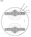
- the structure of the support structure 13 and its arrangement within the shell 9 is particularly good in the in FIG. 3 seen cross section through the paddle 8.
- a honeycomb-shaped support structure 13 is arranged within the shell 9, which has a thickness of _300_ ⁇ m in the present embodiment.
- the support structure 13 is substantially formed by the hollow chambers 15 limiting webs 17 define the running in the longitudinal direction L hexagonal capillary.
- the webs 17 have in present embodiment, a wall thickness of about 50_ ⁇ m on.
- the mechanical oscillator 7 is preferably produced by a generative production method, in particular by a 3-D printing method, in particular 3-D screen printing method. By such a 3-D printing method, the shell 9 and the support structure 13 can be manufactured together.
- cavities can be created by means of appropriate drilling technology. Drills today can have very small diameters up to 0.1 mm. Limiting, is only that break with long holes, the drill or no absolutely straight holes are possible. After such a drilling operation, the top could be closed again by means of a weld.
Landscapes
- Physics & Mathematics (AREA)
- General Physics & Mathematics (AREA)
- Acoustics & Sound (AREA)
- Engineering & Computer Science (AREA)
- Multimedia (AREA)
- Electromagnetism (AREA)
- Thermal Sciences (AREA)
- Fluid Mechanics (AREA)
- Measurement Of Mechanical Vibrations Or Ultrasonic Waves (AREA)
- Micromachines (AREA)
- Apparatuses For Generation Of Mechanical Vibrations (AREA)
Abstract
Description
- Die vorliegende Erfindung betrifft einen Vibrationssensor gemäß dem Oberbegriff des Patentanspruchs 1 sowie ein Verfahren zum Herstellen eines Vibrationssensors gemäß Patentanspruch 9.
- Nach dem Stand der Technik sind Vibrationssensoren, die beispielsweise als Vibrationsgrenzstandschalter verwendet werden, bekannt, wobei der Vibrationssensor eine über einen Antrieb zu einer Schwingung anregbare Membran aufweist, mittels der ein an der Membran angeordneter mechanischer Schwinger zu einer Schwingung anregbar ist. Abhängig von einem Bedeckungsstand des mechanischen Schwingers mit einem Füllgut sowie abhängig von der Viskosität und der Dichte dieses Füllgutes schwingt dieser mit einer charakteristischen Frequenz, die von dem Vibrationssensor detektiert werden und in ein Messsignal umgewandelt werden kann.
- Die mechanischen Schwinger solcher Vibrationssensoren werden beispielsweise durch Metallspritzguß, Guß oder Vakuumguß hergestellt und weisen gemäß dem Stand der Technik eine massive, d. h. vollständig ausgefüllte Form im Bereich des mechanischen Schwingers auf.
- Abhängig von der Masse und Formgebung des mechanischen Schwingers weist dieser ein charakteristisches Schwingungsverhalten in Luft sowie in entsprechenden Messmedien hinsichtlich Frequenz und/oder Amplitude sowie hinsichtlich eines Abklingverhaltens nach einer Anregung auf. In der Regel wird zur Ermittlung des Messsignals eine Frequenzänderung zwischen der Schwingungsfrequenz in der Luft, der sogenannten Luftfrequenz, und der Schwingungsfrequenz eingetaucht im Messmedium, der sogenannten Mediumsfrequenz, ermittelt.
- Aus dem Stand der Technik bekannten Vibrationssensoren wird es nachteilig empfunden, dass die Frequenzänderung von der Luftfrequenz zur Mediumsfrequenz teilweise nicht ausreichend groß ist um Fehldetektionen aufgrund von druckinduzierten und/oder temperaturinduzierten Frequenzschwankungen auszuschließen.
- Es ist die Aufgabe der vorliegenden Erfindung eine Frequenzänderung zwischen der Luftfrequenz und der Mediumsfrequenz zu optimieren, d. h. insbesondere möglichst groß zu gestalten.
- Diese Aufgabe wird durch einen Vibrationssensor mit den Merkmalen des Patentanspruchs 1 gelöst. Ein erfindungsgemäßer Vibrationssensor kann durch das Verfahren zur Herstellung eines Vibrationssensors gemäß Anspruch 9 hergestellt werden.
- Ein erfindungsgemäßer Vibrationssensor mit einer über einen Antrieb zu einer Schwingung anregbaren Membran und einem an der Membran angeordneten mechanischen Schwinger zeichnet sich dadurch aus, dass der mechanische Schwinger eine Hülle mit wenigstens einem geschlossenen Innenraum aufweist. In einer grundlegenden Ausgestaltung ist der mechanische Schwinger gemäß der vorliegenden Erfindung damit hohl ausgestaltet. Dies führt zu einer Gewichtsreduktion im Vergleich zu massiv, d. h. gefüllt ausgestalteten mechanischen Schwingern, zu einer erhöhten Luftfrequenz des mechanischen Schwingers sowie zu einer größeren Frequenzänderung bei Bedeckung des mechanischen Schwingers mit einem Messmedium. Durch eine größere Frequenzänderung werden Fehldetektionen verhindert, so dass insgesamt ein verbessertes Messeergebnis erreicht werden kann.
- Um eine Wandstärke des mechanischen Schwingers weiter zu reduzieren und dennoch eine hohe Stabilität des mechanischen Schwingers erreichen zu können, ist in dem Innenraum des mechanischen Schwingers in einer Weiterbildung der Erfindung eine Füllung, insbesondere eine Füllung mit einer gegenüber der Hülle reduzierten Dichte angeordnet.
- Durch Anordnung einer Füllung im Innenraum des mechanischen Schwingers wird verhindert, dass dieser bei mechanischen Belastungen sehr leicht beschädigt und die Hülle beispielsweis durchstoßen oder verformt wird.
- Die Füllung kann zur Stabilisierung des mechanischen Schwingers beispielsweise als Stützstruktur mit einer Mehrzahl von Hohlkammern und dazwischen angeordneten Stegen ausgebildet sein. Durch eine entsprechende Stützstruktur beispielsweise eine regelmäßig ausgebildete Struktur, die in einem Querschnitt z. B. wabenartig ausgebildet sein kann, wird eine deutliche Erhöhung der Stabilität und Steifigkeit des mechanischen Schwingers erreicht, so dass über die Membran eingeleitete Schwingungen zuverlässig auf den mechanischen Schwinger übertragen werden.
- Alternativ zu einer regelmäßig ausgebildeten Struktur kann der Innenraum auch mit einem geschäumten Material, vorzugsweise einem geschäumten Metall, ausgefüllt sein. Geschäumte Materialien, insbesondere geschäumte Metalle weisen ebenfalls eine hohe Steifigkeit bei gleichzeitiger Gewichtsreduktion auf.
- Die Hülle und/oder die Stützstruktur weist vorzugsweise eine Wandstärke zwischen 50 µm und 500 µm, vorzugsweise zwischen 100 µm und 400 µm weiter vorzugsweise 300 µm.
- Ein Verfahren zur Herstellung eines mechanischen Schwingers eines Vibrationssensors gemäß der vorliegenden Anmeldung zeichnet sich dadurch aus, dass wenigstens eine Hülle des mechanischen Schwingers mit wenigstens einem abgeschlossenen Innenraum ausgebildet und durch ein generatives Fertigungsverfahren hergestellt wird. Im Vergleich zu den bekannten Herstellungsverfahren ist eine hohle Struktur durch ein generatives Fertigungsverfahren, beispielsweise eine 3-D-Druckverfahren besonders einfach herstellbar. Die Hülle kann beispielsweise mit einem Metallschaum ausgeschäumt werden oder es kann eine Metallschaumstruktur mit einer Hülle in einem 3-D-Druckverfahren umdruckt werden.
- Alternativ können die Hülle sowie eine in der Hülle angeordnete Stützstruktur gemeinsam in einem 3-D-Druckverfahren gedruckt werden, wobei sich ein 3-D-Siebdruckverfahren besonders für die Ausbildung hohler Strukturen eignet, da bei einem 3-D-Siebdruckverfahren keine Rückstände des bei 3-D-Druckverfahren typischerweise verwendeten Pulvermaterials in den Hohlräumen zurückbleiben.
- Die vorliegende Erfindung wird nachfolgend anhand eines Ausführungsbeispiels und unter Bezugnahme auf die beigefügten Figuren eingehend erläutert. Es zeigen:
- Figur 1
- eine perspektivische Ansicht eines mechanischen Schwingers gemäß der vorliegenden Anmeldung,
- Figur 2
- die Stützstruktur des mechanischen Schwingers aus Figur 1 in perspektivischer Ansicht und
- Figur 3
- einen Querschnitt durch den mechanischen Schwinger aus
Figur 1 . -
Figur 1 zeigt einen mechanischen Schwinger 7 eines Vibrationssensors 1, der im Wesentlichen als eine an einer Membran 5 angeordnete Stimmgabel ausgebildet ist. Der mechanische Schwinger 7 weist im vorliegenden Ausführungsbeispiel zwei parallel zueinander angeordnete Paddel 8 auf, die über jeweils ein Zwischenstück 4 an der Membran 5 angeordnet und mit dieser verbunden sind. - Im vorliegenden Ausführungsbeispiel sind die Paddel 8 mit einer Hülle 9 sowie einem mit einer als Stützstruktur ausgebildeten Füllung 13 gefüllten Innenraum 11 ausgebildet. Durch das Anordnen der Stützstruktur 13 in der Hülle 9 wird die Verringerung der Stabilität des mechanischen Schwingers 7 minimiert, bei gleichzeitiger Massereduktion, im Vergleich zu einer massiv aufgebauten Variante. Der beispielhafte Aufbau der Füllung 13 sowie deren Ausgestaltung als Stützstruktur ist besonders gut in
Figur 2 zu erkennen. In dieser Darstellung wird besonders deutlich, dass die Füllung 13 mit einer Vielzahl in Längsrichtung der Paddel 8 verlaufenden Hohlkammern 15 versehen ist, die durch Stege 17 begrenzt werden. - Der Aufbau der Stützstruktur 13 sowie deren Anordnung innerhalb der Hülle 9 ist besonders gut in dem in
Figur 3 dargestellten Querschnitt durch die Paddel 8 zu erkennen. Innerhalb der Hülle 9, die im vorliegenden Ausführungsbeispiel eine Dicke von _300_µm aufweist ist eine wabenförmige Stützstruktur 13 angeordnet. Die Stützstruktur 13 ist im Wesentlichen durch die Hohlkammern 15 begrenzende Stege 17 die in Längsrichtung L verlaufende hexagonale Kapillare definieren gebildet. Durch eine derartige Struktur wird eine verwindungssteife und stabile Struktur der Paddel 8 gewährleistet, wobei gleichzeitig deren Gewicht deutlich reduziert wird. Die Stege 17 weisen im vorliegenden Ausführungsbeispiel eine Wandstärke von etwa 50_µm auf. - Durch eine Gewichtsreduktion des mechanischen Schwingers 7 weist dieser eine höhere Resonanzfrequenz in Luft sowie eine größere Frequenzänderung beim Eintauchen in ein Füllmedium im Vergleich zu massiv ausgebildeten mechanischen Schwingern auf, so dass auf diese Weise ein deutlich verbessertes Messverhalten erreicht werden kann. Auf diese Weise wird ein verbesserter Signal-Hub oder im übertragenen Sinne ein verbesserter Signal-Rausch-Abstand erreicht.
Der mechanische Schwinger 7 gemäß der vorliegenden Anmeldung wird vorzugsweise mit einem generativen Herstellungsverfahren, insbesondere mit einem 3-D-Druckverfahren, insbesondere 3-D-Siebdruckverfahren hergestellt. Durch ein solches 3-D-Druckverfahren können die Hülle 9 und die Stützstruktur 13 gemeinsam hergestellt werden. - Bei 3D-Siebdruck-Verfahren können Abstände von über 1mm überdruckt werden.
- Ferner können Hohlräume mittels entsprechender Bohrtechnik erstellt werden. Bohrer können heutzutage sehr kleine Durchmesser bis hin zu 0,1 mm haben. Begrenzend, ist lediglich, dass bei langen Bohrlöchern die Bohrer brechen oder keine absolut geraden Bohrungen mehr möglich sind. Nach einem solchen Bohrvorgang könnte die Oberseite wieder mittels einer Schweißung verschlossen werden.
-
- 1
- Vibrationssensor
- 3
- Antrieb
- 5
- Membran
- 6
- Kragen
- 7
- Mechanischer Schwinger
- 8
- Paddel
- 9
- Hülle
- 11
- Innenraum
- 13
- Füllung/Stützstruktur
- 15
- Hohlkammern
- 17
- Stege
- L
- Längsrichtung
Claims (15)
- Vibrationssensor (1) mit einer über einen Antrieb (3) zu einer Schwingung anregbaren Membran (5) und einem an der Membran (5) angeordneten mechanischen Schwinger (7),
dadurch gekennzeichnet, dass
der mechanisch Schwinger (7) eine Hülle (9) mit wenigstens einem geschlossenen Innenraum (11) aufweist. - Vibrationssensor (1) gemäß Anspruch 1,
dadurch gekennzeichnet, dass
in dem Innenraum (11) eine Füllung (13) angeordnet ist. - Vibrationssensor (1) gemäß Anspruch 2,
dadurch gekennzeichnet, dass
die Füllung (13) eine gegenüber der Hülle (9) reduzierte Dichte aufweist. - Vibrationssensor (1) gemäß Anspruch 2 oder 3,
dadurch gekennzeichnet, dass
die Füllung (13) als Stützstruktur (13) mit einer Mehrzahl von Hohlkammern (15) und dazwischen angeordneten Stegen (17) ausgebildet ist. - Vibrationssensor (1) gemäß einem der vorhergehenden Ansprüche,
dadurch gekennzeichnet, dass
die Stützstruktur (13) regelmäßig ausgebildet ist. - Vibrationssensor (1) gemäß Anspruch 4,
dadurch gekennzeichnet, dass
die Stützstruktur (13) in einem Querschnitt wabenartig ausgebildet ist. - Vibrationssensor (1) gemäß Anspruch 4,
dadurch gekennzeichnet, dass
die Stützstruktur (13) in einem Querschnitt rund ausgebildete Hohlkammern aufweist. - Vibrationssensor (1) gemäß Anspruch 4,
dadurch gekennzeichnet, dass
der Innenraum (11) mit einem geschäumten Material, vorzugsweise einem geschäumten Metall, ausgefüllt ist. - Vibrationssensor (1) gemäß einem der vorhergehenden Ansprüche,
dadurch gekennzeichnet, dass
die Hülle (9) und/oder die Stützstruktur (13) eine Wandstärke zwischen 50 µm und 500 µm, vorzugsweise 100 µm und 400 µm weiter vorzugsweise 300 µm aufweist. - Verfahren zur Herstellung eines mechanischen Schwingers (7) eines Vibrationssensors, wobei wenigstens eine Hülle (9) des mechanischen Schwingers (7) mit wenigstens einem abgeschlossenen Innenraum (9) durch ein generatives Fertigungsverfahren ausgebildet wird.
- Verfahren gemäß Anspruch 9,
dadurch gekennzeichnet, dass
das generative Fertigungsverfahren ein 3D-Druckverfahren ist. - Verfahren gemäß einem der Ansprüche 9 oder 10,
dadurch gekennzeichnet, dass
der Innenraum (13) mit einem Metallschaum ausgeschäumt wird. - Verfahren gemäß Anspruch 10,
dadurch gekennzeichnet, dass
ein Metallschaum mit der Hülle (9) in einem 3D-Druckverfahren umdruckt wird - Verfahren gemäß Anspruche 10,
dadurch gekennzeichnet, dass
die Hülle (9) sowie eine in der Hülle (9) angeordnete Stützstruktur (13) gemeinsam gedruckt werden. - Verfahren gemäß Anspruch 13,
dadurch gekennzeichnet, dass
die Hülle (9) und die Stützstruktur (13) mit einem 3D-Siebdruckverfahren gedruckt werden.
Priority Applications (3)
| Application Number | Priority Date | Filing Date | Title |
|---|---|---|---|
| EP16179986.1A EP3273210B1 (de) | 2016-07-18 | 2016-07-18 | Vibrationsgrenzstandsschalter und verfahren zur herstellung eines vibrationsgrenzstandsschalter |
| US15/628,736 US10845237B2 (en) | 2016-07-18 | 2017-06-21 | Structural implementations for optimizing acoustic resonance in a vibration sensor |
| CN201710560356.4A CN107631794B (zh) | 2016-07-18 | 2017-07-11 | 振动传感器和用于制造振动传感器的方法 |
Applications Claiming Priority (1)
| Application Number | Priority Date | Filing Date | Title |
|---|---|---|---|
| EP16179986.1A EP3273210B1 (de) | 2016-07-18 | 2016-07-18 | Vibrationsgrenzstandsschalter und verfahren zur herstellung eines vibrationsgrenzstandsschalter |
Publications (2)
| Publication Number | Publication Date |
|---|---|
| EP3273210A1 true EP3273210A1 (de) | 2018-01-24 |
| EP3273210B1 EP3273210B1 (de) | 2022-05-18 |
Family
ID=56801358
Family Applications (1)
| Application Number | Title | Priority Date | Filing Date |
|---|---|---|---|
| EP16179986.1A Active EP3273210B1 (de) | 2016-07-18 | 2016-07-18 | Vibrationsgrenzstandsschalter und verfahren zur herstellung eines vibrationsgrenzstandsschalter |
Country Status (3)
| Country | Link |
|---|---|
| US (1) | US10845237B2 (de) |
| EP (1) | EP3273210B1 (de) |
| CN (1) | CN107631794B (de) |
Families Citing this family (1)
| Publication number | Priority date | Publication date | Assignee | Title |
|---|---|---|---|---|
| US10372600B2 (en) * | 2017-03-01 | 2019-08-06 | Salesforce.Com, Inc. | Systems and methods for automated web performance testing for cloud apps in use-case scenarios |
Citations (3)
| Publication number | Priority date | Publication date | Assignee | Title |
|---|---|---|---|---|
| DE4203715A1 (de) * | 1992-02-08 | 1993-08-12 | Vega Grieshaber Gmbh & Co | Vorrichtung zur feststellung und/oder ueberwachung eines vorbestimmten fuellstands in einem behaelter |
| EP2148322A2 (de) * | 2008-07-15 | 2010-01-27 | Krohne AG | Ultraschallwandler |
| DE102014115589A1 (de) * | 2014-10-27 | 2016-04-28 | Endress + Hauser Flowtec Ag | Anordnung zum Aussenden und/oder Empfangen eines Ultraschall-Nutzsignals und Ultraschall-Durchflussmessgerät |
Family Cites Families (21)
| Publication number | Priority date | Publication date | Assignee | Title |
|---|---|---|---|---|
| US4817165A (en) * | 1987-01-27 | 1989-03-28 | Amalaha Leonard D | Acoustic speaker device with a diaphragm having a spider web type core |
| GB9704486D0 (en) * | 1997-03-04 | 1997-04-23 | New Transducers Ltd | Acoustic devices etc |
| US6282298B1 (en) * | 1996-09-03 | 2001-08-28 | New Transducers Limited | Acoustic device |
| DE10242970A1 (de) * | 2002-09-17 | 2004-04-01 | Vega Grieshaber Kg | Vibrations-Füllstandssensor |
| JP4529444B2 (ja) * | 2004-01-13 | 2010-08-25 | パナソニック株式会社 | 角速度センサ |
| DE102004009495B4 (de) * | 2004-02-27 | 2009-09-24 | Vega Grieshaber Kg | Abgleichkörper für eine Füllstandsmessvorrichtung |
| DE102006046251A1 (de) * | 2006-09-28 | 2008-04-03 | Vega Grieshaber Kg | Piezoelektrisch erregbare Schwingvorrichtung |
| US20080105049A1 (en) * | 2006-11-02 | 2008-05-08 | Vega Grieshaber Kg | Vibrating device with piezo-electrical excitation |
| US9293800B2 (en) * | 2010-12-10 | 2016-03-22 | Northrop Grumman Systems Corporation | RF transmission line disposed within a conductively plated cavity located in a low mass foam housing |
| DE102011075113A1 (de) * | 2011-05-03 | 2012-11-08 | Endress + Hauser Gmbh + Co. Kg | Vorrichtung und Verfahren zum Betreiben einer Vorrichtung zur Bestimmung und/oder Überwachung mindestens einer physikalischen Prozessgröße |
| HK1198350A1 (en) * | 2011-07-21 | 2015-04-02 | C-Eng Co., Ltd. | Self-resonating sound emitting speaker and method for installing self-resonating sound emitting speaker |
| DE102012100728A1 (de) * | 2012-01-30 | 2013-08-01 | Endress + Hauser Gmbh + Co. Kg | Vorrichtung zur Bestimmung und/oder Überwachung mindestens einer Prozessgröße |
| DE102012208059B4 (de) * | 2012-05-14 | 2022-05-12 | Robert Bosch Gmbh | Trägerelement mit integrierter Sensoreinheit |
| JP6175780B2 (ja) * | 2013-01-28 | 2017-08-09 | セイコーエプソン株式会社 | 超音波デバイス、超音波プローブ、電子機器および超音波画像装置 |
| JP5742868B2 (ja) * | 2013-04-11 | 2015-07-01 | 株式会社大真空 | 音叉型水晶振動片、及び水晶振動デバイス |
| EP2803954B1 (de) * | 2013-05-15 | 2019-01-02 | VEGA Grieshaber KG | Füllstandmessvorrichtung |
| JP6375611B2 (ja) * | 2013-11-16 | 2018-08-22 | セイコーエプソン株式会社 | 振動片、振動子、発振器、電子機器および移動体 |
| DE102014101372B4 (de) * | 2014-02-04 | 2015-10-08 | Vega Grieshaber Kg | Vibrationssensor mit geklebtem Antrieb |
| US20160117015A1 (en) * | 2014-10-28 | 2016-04-28 | Stmicroelectronics S.R.L. | Microelectromechanical vibration sensor |
| US10752999B2 (en) * | 2016-04-18 | 2020-08-25 | Rolls-Royce Corporation | High strength aerospace components |
| JP2019102826A (ja) * | 2017-11-28 | 2019-06-24 | 京セラ株式会社 | 音叉型水晶振動素子及び圧電デバイス |
-
2016
- 2016-07-18 EP EP16179986.1A patent/EP3273210B1/de active Active
-
2017
- 2017-06-21 US US15/628,736 patent/US10845237B2/en active Active
- 2017-07-11 CN CN201710560356.4A patent/CN107631794B/zh active Active
Patent Citations (3)
| Publication number | Priority date | Publication date | Assignee | Title |
|---|---|---|---|---|
| DE4203715A1 (de) * | 1992-02-08 | 1993-08-12 | Vega Grieshaber Gmbh & Co | Vorrichtung zur feststellung und/oder ueberwachung eines vorbestimmten fuellstands in einem behaelter |
| EP2148322A2 (de) * | 2008-07-15 | 2010-01-27 | Krohne AG | Ultraschallwandler |
| DE102014115589A1 (de) * | 2014-10-27 | 2016-04-28 | Endress + Hauser Flowtec Ag | Anordnung zum Aussenden und/oder Empfangen eines Ultraschall-Nutzsignals und Ultraschall-Durchflussmessgerät |
Also Published As
| Publication number | Publication date |
|---|---|
| CN107631794A (zh) | 2018-01-26 |
| US10845237B2 (en) | 2020-11-24 |
| EP3273210B1 (de) | 2022-05-18 |
| US20180017433A1 (en) | 2018-01-18 |
| CN107631794B (zh) | 2021-10-26 |
Similar Documents
| Publication | Publication Date | Title |
|---|---|---|
| EP2464951B1 (de) | Multivariabler sensor zur bestimmung und/oder überwachung des füllstands und der dichte und/oder der viskosität einer flüssigkeit im behälter | |
| DE3417858C2 (de) | ||
| EP3333552B1 (de) | Ultraschall-durchflussmessvorrichtung und ihr herstellungsverfahren | |
| DE3013185C2 (de) | ||
| EP3368867B1 (de) | Mems sensor zu messung mindestens einer messgrösse eines fluids | |
| DE1773815A1 (de) | Vorrichtung zur Feststellung des Fuellstands eines Behaelters | |
| EP3213041B1 (de) | Vibronischer sensor | |
| EP3338064B1 (de) | Ultraschallwandler mit einem hohlraum und verfahren zur herstellung eines ultraschallwandlers | |
| WO2007147786A1 (de) | Sensor in mikromechanischer bauweise zum messen des massendurchflusse nach dem coriolis-prinzip | |
| DE3215040A1 (de) | Resonanzstab | |
| WO2024126024A1 (de) | VORRICHTUNG ZUR BESTIMMUNG UND/ODER ÜBERWACHUNG ZUMINDEST EINER PROZESSGRÖßE EINES MEDIUMS | |
| WO2018149574A1 (de) | Verbesserte klebeverbindung durch mikrostrukturierung einer oberfläche mittels laser | |
| EP3246668A1 (de) | Messvorrichtung und verfahren zum bestimmen der strömungsgeschwindigkeit eines in einer leitung strömenden fluids | |
| AT524995B1 (de) | Verfahren und Vorrichtung zur Entfernung von Stützstrukturen aus einem Gegenstand, sowie Verfahren zur Herstellung eines Gegenstands durch additive Fertigung | |
| EP3273210B1 (de) | Vibrationsgrenzstandsschalter und verfahren zur herstellung eines vibrationsgrenzstandsschalter | |
| DE4213135A1 (de) | Beschleunigungssensor und Verfahren zu dessen Herstellung | |
| DE102015118347A1 (de) | Messaufnehmer mit einer zu Schwingungen anregbaren Messleitung | |
| EP1751507B1 (de) | Vorrichtung zur bestimmung und/oder überwachung einer prozessgrösse eines mediums | |
| DE102023118598A1 (de) | Vibrationssensor | |
| EP1914526A1 (de) | Meßaufnehmer vom Vibrationstyp | |
| EP0142560B1 (de) | Zylindrischer hohlkörper für messwandler zum messen des druckes eines fluids | |
| EP2545386B1 (de) | Beschleunigungssensor mit piezoresistivem wandler | |
| DE10153937A1 (de) | Vorrichtung zur Feststellung und/oder Überwachung eines vorbestimmten Füllstandes in einem Behälter | |
| DE19838284C1 (de) | Vorrichtung zur Bestimmung der Dichte einer Flüssigkeit | |
| DE102004023600A1 (de) | Sensor zur Bestimmung von Massendurchfluss und Dichte strömender Medien sowie Verfahren zur Betätigung des Sensors |
Legal Events
| Date | Code | Title | Description |
|---|---|---|---|
| PUAI | Public reference made under article 153(3) epc to a published international application that has entered the european phase |
Free format text: ORIGINAL CODE: 0009012 |
|
| STAA | Information on the status of an ep patent application or granted ep patent |
Free format text: STATUS: THE APPLICATION HAS BEEN PUBLISHED |
|
| AK | Designated contracting states |
Kind code of ref document: A1 Designated state(s): AL AT BE BG CH CY CZ DE DK EE ES FI FR GB GR HR HU IE IS IT LI LT LU LV MC MK MT NL NO PL PT RO RS SE SI SK SM TR |
|
| AX | Request for extension of the european patent |
Extension state: BA ME |
|
| STAA | Information on the status of an ep patent application or granted ep patent |
Free format text: STATUS: REQUEST FOR EXAMINATION WAS MADE |
|
| 17P | Request for examination filed |
Effective date: 20180530 |
|
| RBV | Designated contracting states (corrected) |
Designated state(s): AL AT BE BG CH CY CZ DE DK EE ES FI FR GB GR HR HU IE IS IT LI LT LU LV MC MK MT NL NO PL PT RO RS SE SI SK SM TR |
|
| STAA | Information on the status of an ep patent application or granted ep patent |
Free format text: STATUS: EXAMINATION IS IN PROGRESS |
|
| 17Q | First examination report despatched |
Effective date: 20210511 |
|
| GRAP | Despatch of communication of intention to grant a patent |
Free format text: ORIGINAL CODE: EPIDOSNIGR1 |
|
| STAA | Information on the status of an ep patent application or granted ep patent |
Free format text: STATUS: GRANT OF PATENT IS INTENDED |
|
| INTG | Intention to grant announced |
Effective date: 20211214 |
|
| GRAS | Grant fee paid |
Free format text: ORIGINAL CODE: EPIDOSNIGR3 |
|
| GRAA | (expected) grant |
Free format text: ORIGINAL CODE: 0009210 |
|
| STAA | Information on the status of an ep patent application or granted ep patent |
Free format text: STATUS: THE PATENT HAS BEEN GRANTED |
|
| AK | Designated contracting states |
Kind code of ref document: B1 Designated state(s): AL AT BE BG CH CY CZ DE DK EE ES FI FR GB GR HR HU IE IS IT LI LT LU LV MC MK MT NL NO PL PT RO RS SE SI SK SM TR |
|
| REG | Reference to a national code |
Ref country code: GB Ref legal event code: FG4D Free format text: NOT ENGLISH |
|
| RIN1 | Information on inventor provided before grant (corrected) |
Inventor name: FEHRENBACH, DOMINIK Inventor name: ALLGAIER, VOLKER |
|
| REG | Reference to a national code |
Ref country code: CH Ref legal event code: EP |
|
| REG | Reference to a national code |
Ref country code: IE Ref legal event code: FG4D Free format text: LANGUAGE OF EP DOCUMENT: GERMAN |
|
| REG | Reference to a national code |
Ref country code: DE Ref legal event code: R096 Ref document number: 502016014892 Country of ref document: DE |
|
| REG | Reference to a national code |
Ref country code: AT Ref legal event code: REF Ref document number: 1493416 Country of ref document: AT Kind code of ref document: T Effective date: 20220615 |
|
| REG | Reference to a national code |
Ref country code: LT Ref legal event code: MG9D |
|
| REG | Reference to a national code |
Ref country code: NL Ref legal event code: MP Effective date: 20220518 |
|
| PG25 | Lapsed in a contracting state [announced via postgrant information from national office to epo] |
Ref country code: SE Free format text: LAPSE BECAUSE OF FAILURE TO SUBMIT A TRANSLATION OF THE DESCRIPTION OR TO PAY THE FEE WITHIN THE PRESCRIBED TIME-LIMIT Effective date: 20220518 Ref country code: PT Free format text: LAPSE BECAUSE OF FAILURE TO SUBMIT A TRANSLATION OF THE DESCRIPTION OR TO PAY THE FEE WITHIN THE PRESCRIBED TIME-LIMIT Effective date: 20220919 Ref country code: NO Free format text: LAPSE BECAUSE OF FAILURE TO SUBMIT A TRANSLATION OF THE DESCRIPTION OR TO PAY THE FEE WITHIN THE PRESCRIBED TIME-LIMIT Effective date: 20220818 Ref country code: NL Free format text: LAPSE BECAUSE OF FAILURE TO SUBMIT A TRANSLATION OF THE DESCRIPTION OR TO PAY THE FEE WITHIN THE PRESCRIBED TIME-LIMIT Effective date: 20220518 Ref country code: LT Free format text: LAPSE BECAUSE OF FAILURE TO SUBMIT A TRANSLATION OF THE DESCRIPTION OR TO PAY THE FEE WITHIN THE PRESCRIBED TIME-LIMIT Effective date: 20220518 Ref country code: HR Free format text: LAPSE BECAUSE OF FAILURE TO SUBMIT A TRANSLATION OF THE DESCRIPTION OR TO PAY THE FEE WITHIN THE PRESCRIBED TIME-LIMIT Effective date: 20220518 Ref country code: GR Free format text: LAPSE BECAUSE OF FAILURE TO SUBMIT A TRANSLATION OF THE DESCRIPTION OR TO PAY THE FEE WITHIN THE PRESCRIBED TIME-LIMIT Effective date: 20220819 Ref country code: FI Free format text: LAPSE BECAUSE OF FAILURE TO SUBMIT A TRANSLATION OF THE DESCRIPTION OR TO PAY THE FEE WITHIN THE PRESCRIBED TIME-LIMIT Effective date: 20220518 Ref country code: ES Free format text: LAPSE BECAUSE OF FAILURE TO SUBMIT A TRANSLATION OF THE DESCRIPTION OR TO PAY THE FEE WITHIN THE PRESCRIBED TIME-LIMIT Effective date: 20220518 Ref country code: BG Free format text: LAPSE BECAUSE OF FAILURE TO SUBMIT A TRANSLATION OF THE DESCRIPTION OR TO PAY THE FEE WITHIN THE PRESCRIBED TIME-LIMIT Effective date: 20220818 |
|
| PG25 | Lapsed in a contracting state [announced via postgrant information from national office to epo] |
Ref country code: RS Free format text: LAPSE BECAUSE OF FAILURE TO SUBMIT A TRANSLATION OF THE DESCRIPTION OR TO PAY THE FEE WITHIN THE PRESCRIBED TIME-LIMIT Effective date: 20220518 Ref country code: PL Free format text: LAPSE BECAUSE OF FAILURE TO SUBMIT A TRANSLATION OF THE DESCRIPTION OR TO PAY THE FEE WITHIN THE PRESCRIBED TIME-LIMIT Effective date: 20220518 Ref country code: LV Free format text: LAPSE BECAUSE OF FAILURE TO SUBMIT A TRANSLATION OF THE DESCRIPTION OR TO PAY THE FEE WITHIN THE PRESCRIBED TIME-LIMIT Effective date: 20220518 Ref country code: IS Free format text: LAPSE BECAUSE OF FAILURE TO SUBMIT A TRANSLATION OF THE DESCRIPTION OR TO PAY THE FEE WITHIN THE PRESCRIBED TIME-LIMIT Effective date: 20220918 |
|
| PG25 | Lapsed in a contracting state [announced via postgrant information from national office to epo] |
Ref country code: SM Free format text: LAPSE BECAUSE OF FAILURE TO SUBMIT A TRANSLATION OF THE DESCRIPTION OR TO PAY THE FEE WITHIN THE PRESCRIBED TIME-LIMIT Effective date: 20220518 Ref country code: SK Free format text: LAPSE BECAUSE OF FAILURE TO SUBMIT A TRANSLATION OF THE DESCRIPTION OR TO PAY THE FEE WITHIN THE PRESCRIBED TIME-LIMIT Effective date: 20220518 Ref country code: RO Free format text: LAPSE BECAUSE OF FAILURE TO SUBMIT A TRANSLATION OF THE DESCRIPTION OR TO PAY THE FEE WITHIN THE PRESCRIBED TIME-LIMIT Effective date: 20220518 Ref country code: EE Free format text: LAPSE BECAUSE OF FAILURE TO SUBMIT A TRANSLATION OF THE DESCRIPTION OR TO PAY THE FEE WITHIN THE PRESCRIBED TIME-LIMIT Effective date: 20220518 Ref country code: DK Free format text: LAPSE BECAUSE OF FAILURE TO SUBMIT A TRANSLATION OF THE DESCRIPTION OR TO PAY THE FEE WITHIN THE PRESCRIBED TIME-LIMIT Effective date: 20220518 Ref country code: CZ Free format text: LAPSE BECAUSE OF FAILURE TO SUBMIT A TRANSLATION OF THE DESCRIPTION OR TO PAY THE FEE WITHIN THE PRESCRIBED TIME-LIMIT Effective date: 20220518 |
|
| REG | Reference to a national code |
Ref country code: DE Ref legal event code: R097 Ref document number: 502016014892 Country of ref document: DE |
|
| PG25 | Lapsed in a contracting state [announced via postgrant information from national office to epo] |
Ref country code: MC Free format text: LAPSE BECAUSE OF FAILURE TO SUBMIT A TRANSLATION OF THE DESCRIPTION OR TO PAY THE FEE WITHIN THE PRESCRIBED TIME-LIMIT Effective date: 20220518 |
|
| REG | Reference to a national code |
Ref country code: CH Ref legal event code: PL |
|
| PLBE | No opposition filed within time limit |
Free format text: ORIGINAL CODE: 0009261 |
|
| STAA | Information on the status of an ep patent application or granted ep patent |
Free format text: STATUS: NO OPPOSITION FILED WITHIN TIME LIMIT |
|
| REG | Reference to a national code |
Ref country code: BE Ref legal event code: MM Effective date: 20220731 |
|
| PG25 | Lapsed in a contracting state [announced via postgrant information from national office to epo] |
Ref country code: AL Free format text: LAPSE BECAUSE OF FAILURE TO SUBMIT A TRANSLATION OF THE DESCRIPTION OR TO PAY THE FEE WITHIN THE PRESCRIBED TIME-LIMIT Effective date: 20220518 |
|
| 26N | No opposition filed |
Effective date: 20230221 |
|
| PG25 | Lapsed in a contracting state [announced via postgrant information from national office to epo] |
Ref country code: LU Free format text: LAPSE BECAUSE OF NON-PAYMENT OF DUE FEES Effective date: 20220718 Ref country code: LI Free format text: LAPSE BECAUSE OF NON-PAYMENT OF DUE FEES Effective date: 20220731 Ref country code: FR Free format text: LAPSE BECAUSE OF NON-PAYMENT OF DUE FEES Effective date: 20220718 Ref country code: CH Free format text: LAPSE BECAUSE OF NON-PAYMENT OF DUE FEES Effective date: 20220731 |
|
| PG25 | Lapsed in a contracting state [announced via postgrant information from national office to epo] |
Ref country code: SI Free format text: LAPSE BECAUSE OF FAILURE TO SUBMIT A TRANSLATION OF THE DESCRIPTION OR TO PAY THE FEE WITHIN THE PRESCRIBED TIME-LIMIT Effective date: 20220518 Ref country code: BE Free format text: LAPSE BECAUSE OF NON-PAYMENT OF DUE FEES Effective date: 20220731 |
|
| PG25 | Lapsed in a contracting state [announced via postgrant information from national office to epo] |
Ref country code: IE Free format text: LAPSE BECAUSE OF NON-PAYMENT OF DUE FEES Effective date: 20220718 |
|
| P01 | Opt-out of the competence of the unified patent court (upc) registered |
Effective date: 20230626 |
|
| REG | Reference to a national code |
Ref country code: AT Ref legal event code: MM01 Ref document number: 1493416 Country of ref document: AT Kind code of ref document: T Effective date: 20220718 |
|
| PG25 | Lapsed in a contracting state [announced via postgrant information from national office to epo] |
Ref country code: AT Free format text: LAPSE BECAUSE OF NON-PAYMENT OF DUE FEES Effective date: 20220718 |
|
| PG25 | Lapsed in a contracting state [announced via postgrant information from national office to epo] |
Ref country code: IT Free format text: LAPSE BECAUSE OF FAILURE TO SUBMIT A TRANSLATION OF THE DESCRIPTION OR TO PAY THE FEE WITHIN THE PRESCRIBED TIME-LIMIT Effective date: 20220518 |
|
| PG25 | Lapsed in a contracting state [announced via postgrant information from national office to epo] |
Ref country code: HU Free format text: LAPSE BECAUSE OF FAILURE TO SUBMIT A TRANSLATION OF THE DESCRIPTION OR TO PAY THE FEE WITHIN THE PRESCRIBED TIME-LIMIT; INVALID AB INITIO Effective date: 20160718 |
|
| PG25 | Lapsed in a contracting state [announced via postgrant information from national office to epo] |
Ref country code: MK Free format text: LAPSE BECAUSE OF FAILURE TO SUBMIT A TRANSLATION OF THE DESCRIPTION OR TO PAY THE FEE WITHIN THE PRESCRIBED TIME-LIMIT Effective date: 20220511 Ref country code: CY Free format text: LAPSE BECAUSE OF FAILURE TO SUBMIT A TRANSLATION OF THE DESCRIPTION OR TO PAY THE FEE WITHIN THE PRESCRIBED TIME-LIMIT Effective date: 20220511 |
|
| PG25 | Lapsed in a contracting state [announced via postgrant information from national office to epo] |
Ref country code: MT Free format text: LAPSE BECAUSE OF FAILURE TO SUBMIT A TRANSLATION OF THE DESCRIPTION OR TO PAY THE FEE WITHIN THE PRESCRIBED TIME-LIMIT Effective date: 20220511 |
|
| PG25 | Lapsed in a contracting state [announced via postgrant information from national office to epo] |
Ref country code: BG Free format text: LAPSE BECAUSE OF FAILURE TO SUBMIT A TRANSLATION OF THE DESCRIPTION OR TO PAY THE FEE WITHIN THE PRESCRIBED TIME-LIMIT Effective date: 20220518 |
|
| PG25 | Lapsed in a contracting state [announced via postgrant information from national office to epo] |
Ref country code: BG Free format text: LAPSE BECAUSE OF FAILURE TO SUBMIT A TRANSLATION OF THE DESCRIPTION OR TO PAY THE FEE WITHIN THE PRESCRIBED TIME-LIMIT Effective date: 20220518 |
|
| PGFP | Annual fee paid to national office [announced via postgrant information from national office to epo] |
Ref country code: DE Payment date: 20250722 Year of fee payment: 10 |
|
| PGFP | Annual fee paid to national office [announced via postgrant information from national office to epo] |
Ref country code: GB Payment date: 20250724 Year of fee payment: 10 |
|
| PG25 | Lapsed in a contracting state [announced via postgrant information from national office to epo] |
Ref country code: TR Free format text: LAPSE BECAUSE OF FAILURE TO SUBMIT A TRANSLATION OF THE DESCRIPTION OR TO PAY THE FEE WITHIN THE PRESCRIBED TIME-LIMIT Effective date: 20220518 |