EP3273091B1 - Verfahren und produkt für konische feder mit veränderlicher steifheit und mit fähigkeit zur verhinderung von faltung und spaltung - Google Patents
Verfahren und produkt für konische feder mit veränderlicher steifheit und mit fähigkeit zur verhinderung von faltung und spaltung Download PDFInfo
- Publication number
- EP3273091B1 EP3273091B1 EP15885051.1A EP15885051A EP3273091B1 EP 3273091 B1 EP3273091 B1 EP 3273091B1 EP 15885051 A EP15885051 A EP 15885051A EP 3273091 B1 EP3273091 B1 EP 3273091B1
- Authority
- EP
- European Patent Office
- Prior art keywords
- rubber
- section
- rubber body
- conical
- stiffness
- Prior art date
- Legal status (The legal status is an assumption and is not a legal conclusion. Google has not performed a legal analysis and makes no representation as to the accuracy of the status listed.)
- Active
Links
Images



Classifications
-
- F—MECHANICAL ENGINEERING; LIGHTING; HEATING; WEAPONS; BLASTING
- F16—ENGINEERING ELEMENTS AND UNITS; GENERAL MEASURES FOR PRODUCING AND MAINTAINING EFFECTIVE FUNCTIONING OF MACHINES OR INSTALLATIONS; THERMAL INSULATION IN GENERAL
- F16F—SPRINGS; SHOCK-ABSORBERS; MEANS FOR DAMPING VIBRATION
- F16F1/00—Springs
- F16F1/36—Springs made of rubber or other material having high internal friction, e.g. thermoplastic elastomers
- F16F1/38—Springs made of rubber or other material having high internal friction, e.g. thermoplastic elastomers with a sleeve of elastic material between a rigid outer sleeve and a rigid inner sleeve or pin, i.e. bushing-type
- F16F1/393—Springs made of rubber or other material having high internal friction, e.g. thermoplastic elastomers with a sleeve of elastic material between a rigid outer sleeve and a rigid inner sleeve or pin, i.e. bushing-type with spherical or conical sleeves
- F16F1/3935—Conical sleeves
-
- F—MECHANICAL ENGINEERING; LIGHTING; HEATING; WEAPONS; BLASTING
- F16—ENGINEERING ELEMENTS AND UNITS; GENERAL MEASURES FOR PRODUCING AND MAINTAINING EFFECTIVE FUNCTIONING OF MACHINES OR INSTALLATIONS; THERMAL INSULATION IN GENERAL
- F16F—SPRINGS; SHOCK-ABSORBERS; MEANS FOR DAMPING VIBRATION
- F16F1/00—Springs
- F16F1/36—Springs made of rubber or other material having high internal friction, e.g. thermoplastic elastomers
- F16F1/38—Springs made of rubber or other material having high internal friction, e.g. thermoplastic elastomers with a sleeve of elastic material between a rigid outer sleeve and a rigid inner sleeve or pin, i.e. bushing-type
- F16F1/3828—End stop features or buffering
-
- F—MECHANICAL ENGINEERING; LIGHTING; HEATING; WEAPONS; BLASTING
- F16—ENGINEERING ELEMENTS AND UNITS; GENERAL MEASURES FOR PRODUCING AND MAINTAINING EFFECTIVE FUNCTIONING OF MACHINES OR INSTALLATIONS; THERMAL INSULATION IN GENERAL
- F16F—SPRINGS; SHOCK-ABSORBERS; MEANS FOR DAMPING VIBRATION
- F16F1/00—Springs
- F16F1/36—Springs made of rubber or other material having high internal friction, e.g. thermoplastic elastomers
- F16F1/38—Springs made of rubber or other material having high internal friction, e.g. thermoplastic elastomers with a sleeve of elastic material between a rigid outer sleeve and a rigid inner sleeve or pin, i.e. bushing-type
- F16F1/3863—Springs made of rubber or other material having high internal friction, e.g. thermoplastic elastomers with a sleeve of elastic material between a rigid outer sleeve and a rigid inner sleeve or pin, i.e. bushing-type characterised by the rigid sleeves or pin, e.g. of non-circular cross-section
Definitions
- a conical spring also called journal box spring, mainly refers to a spring with a shock absorption effect formed by combining metal with rubber on a locomotive.
- the conical spring is installed between a journal box and a frame of a rail locomotive to achieve the effects of support, shock absorption and noise reduction, is a frequently-used shock-absorption and noise-reduction element formed by combining rubber with metal, is installed on a locomotive body of single-stage suspension and two-stage suspension of the locomotive, and is mainly used for bearing the load of the locomotive body and the frame.
- the inverse S curve occurs to the vertical stiffness is because that a rubber body of the existing conical spring structure has no strong mutual extrusion and has no extrusion of contact between an externally protruded lug boss and rubber, the vertical changeable stiffness of the conical spring is too small under no load, when the locomotive is under load, especially under the maximum vertical load, when it is required that the rubber part of the conical spring should provide sufficiently large vertical stiffness, but the existing conical spring cannot provide large changeable stiffness, so that ideal changeable stiffness cannot be achieved, and thus the stiffness curve presents inverse "S".
- the conical spring having an inverse "S" curve has large stiffness under no load, so that the risk of derail of the locomotive may be caused.
- the conical spring has appropriate transverse changeable stiffness and longitudinal changeable stiffness, so that the locomotive more meets dynamics requirements, thereby having good effects of transverse and longitudinal shock absorption and noise reduction. Therefore, by appropriately increasing the number of transverse changeable stiffness and longitudinal changeable stiffness of the locomotive to achieve multiple changes of stiffness, the locomotive may be made to run more steady and smooth. Because the conical spring is a whole formed by vulcanizing metal and rubber, which cannot be disassembled and cannot be conveniently repaired locally, the conical spring is a lifelong maintenance-free product. With the development of technique of locomotives, the fatigue load thereof becomes harsh more and more, and the requirement for fatigue performance becomes strict more and more.
- the invention relates to a journal box spring for a bogie of an urban rail train.
- An outer ring of a spindle is provided with a spacer sleeve I, a spacer sleeve II and an outer sleeve in sequence from inside to outside.
- the spindle, the spacer sleeve I, the spacer sleeve II and the outer sleeve are all made of metal materials, and a rubber layer III, a rubber layer II and a rubber layer I are respectively arranged between two adjacent metal materials.
- the exposed metal surface of each of the spindle, the spacer sleeve I, the spacer sleeve II and the outer sleeve is coated with base paint and surface paint.
- the invention has the advantage that a journal box spring for a bogie of an urban rail train which has small vertical, transverse and longitudinal static stiffness when train wheels move and can improve the flexibility and quality when the train runs.
- the utility model comprises an outer sleeve, an inner sleeve, an inner core, a first rubber layer and a second rubber layer, and is characterized in that the first rubber layer and the second rubber layer are vulcanized into a whole together with the outer sleeve, the inner sleeve and the inner core, the outer sleeve is connected to the inner core through a copper conducting wire built in the surface of the first rubber layer and the second rubber layer, and the included angle between the side extension of the first rubber layer and the second rubber layer and the top of the plane journal box spring is 100-160°.
- the utility model mainly relates to a journal box spring used on a bogie of an overloaded railway wagon.
- the patent for utility models does not make the journal box spring implement multiple changeable stiffness structure, so that it is difficult to meet multiple changes of stiffness required by a locomotive in different states.
- JP 5069972 discloses a conical spring according to the preamble of claim 5 and a method of changing stiffness and preventing folding and cracking of a conical spring according to the preamble of claim 5.
- CN 201 461 844 U discloses a further conical spring assembly.
- the shape of each section is a straight line or arc shape, and every two sections are connected through arc section transition, to guarantee that in the process of downwards moving the upper end of the rubber body, the shape of the upper end of the rubber body is always kept as a smooth shape, so that no fold and crack may be generated.
- the shape of each section is a straight line or arc shape, every two sections are connected through arc section transition, to guarantee that in the process of downwards moving the rubber body, the shape of the lower end surface of the rubber body is always kept as a smooth shape, so that no fold and crack may be generated.
- a lug boss is externally protruded from the bottom of the inner conical body, and after the rubber body downwards moves to the lower end surface of the rubber body and comes into contact with the lug boss, substantial changeable stiffness is generated by the cooperation of double restriction of the lug boss externally protruded from the bottom of the inner conical body and the inner side of the outer conical body; under the action of vertical load, the lower end surface of the rubber body is simultaneously closely fitted with the inner side of the outer conical body and the externally protruded lug boss of the lower part of the inner conical body gradually in a rolling mode, to achieve substantial changeable stiffness.
- the upper surface of the lug boss is of a multi-section structure, every two sections adopt an arc section for transition, the extent of stiffness change and the position of stiffness change are adjusted by adjusting the shape, slope and length of each section of the lug boss and the opening angle of the inner side of the outer conical body, and the adjustment of multiple stiffness changes is achieved by controlling the number of multiple sections.
- a conical spring for carrying out the above method for changing stiffness and preventing folding and cracking of the conical spring which comprises an inner conical body, a rubber body and an outer conical body.
- the rubber body encircles the periphery of the inner conical body.
- the outer conical body encircles the periphery of the rubber body.
- the rubber body, the inner conical body and the outer conical body form a conical rubber metal spring together;
- the method of the invention has the characteristic that an upper rubber profile of the rubber body of the conical spring and a lower rubber profile of the rubber body adopt a multi-section structure form, wherein the upper rubber profile of the rubber body is of a multi-section downslope structure form, and the lower rubber profile of the rubber body is of a multi-section upslope structure.
- the shape of each section is a straight line or arc shape, every two sections adopt an arc section for transition, to guarantee that in the process of downwards moving the rubber body, the shape of the lower end surface of the rubber body is always kept as a smooth shape, so that no fold and crack may be generated.
- a lug boss is externally protruded from the bottom of the inner conical body, after the rubber body downwards moves to the lower end surface of the rubber body and comes into contact with the lug boss, substantial changeable stiffness is generated by the cooperation of double restriction of the lug boss externally protruded from the bottom of the inner conical body and the inner side of the outer conical body; under the action of vertical load, the lower end surface of the rubber body is simultaneously closely fitted with the inner side of the outer conical body and the externally protruded lug boss of the lower part of the inner conical body gradually in a rolling mode, to achieve substantial changeable stiffness.
- the upper surface of the lug boss is of a multi-section structure, every two sections adopt an arc section for transition, and the extent of stiffness change and the position of stiffness change are adjusted by adjusting the shape, slope and length of each section of the lug boss and the opening angle of the inner side of the outer conical body; and the adjustment of multiple stiffness changes is achieved by controlling the number of multiple sections.
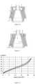
- a conical spring comprising an inner conical body 1, a rubber body 2 and an outer conical body 3, wherein the lower end of the inner conical body 1 extends to the outer side to form an annular inner conical body lug boss 11.
- the upper end surface of the rubber body 2 is of a multi-section downslope structure of three sections which are a first annular straight section 211, a second annular straight section 212 and a third annular straight section 213 respectively, and every two annular straight sections adopt the annular fillet section 22 for transition.
- any one of the first annular straight section 211 and the second annular straight section is inwards tilted rather than outwards tilted as in Figure 1 .
- the shape of the upper end of the rubber body 2 may present a fold similar to that at E in Figure 11 in the process of downwards moving the rubber body 2.
- the Table shows the included angle between each annular straight section of the rubber body 2 in this embodiment and the vertical direction and the length of each annular straight section.
- each conical spring is subjected to a vertical load of about 14KN-18KN, it can be seen from Figure 12 that 14KN-18KN is at the inverse S curve of the vertical stiffness of the conical spring.
- the inverse S curve has the characteristic that the distance of downward movement of the rubber body 2 is not large, but the stiffness thereof is increased quickly, and such stiffness increase mode is not beneficial to the shock absorption of the locomotive, which may cause the risk of derail of the locomotive.
Landscapes
- Engineering & Computer Science (AREA)
- General Engineering & Computer Science (AREA)
- Mechanical Engineering (AREA)
- Springs (AREA)
Claims (11)
- Verfahren zum Ändern der Steifigkeit und zum Vermeiden von Falten und Rissen in einer konischen Federwobei die konische Feder einen inneren konischen Körper (1), einen Gummikörper (2) und einen äußeren konischen Körper (3) aufweist, wobei der Gummikörper (2) den Umfang des inneren konischen Körpers (1) umgibt, der äußere konische Körper (3) den Umfang des Gummikörpers (2) umgibt, der Gummikörper (2), der innere konische Körper (1) und der äußere konische Körper (3) zusammen eine konische Gummimetallfeder bilden,wobei ein oberes Gummiprofil des Gummikörpers und ein unteres Gummiprofil des Gummikörpers (2) der konischen Feder eine mehrteilige Strukturform annehmen, wobei das obere Gummiprofil des Gummikörpers eine mehrteilige abfallende Struktur aufweist und das untere Gummiprofil des Gummikörpers (2) eine mehrteilige ansteigende Struktur aufweist, bei der konischen Feder das Ausmaß der Steifigkeitsänderung und die Position der Steifigkeitsänderung der konischen Feder durch Einstellen der Form, der Neigung und der Länge jedes Abschnitts in der mehrteiligen abfallenden Struktur des oberen Gummiprofils des Gummikörpers (2) und der mehrteiligen ansteigenden Struktur des unteren Gummiprofils des Gummikörpers eingestellt werden, und die Einstellung von mehrfachen Steifigkeitsänderungen durch Steuern der Anzahl von mehreren Abschnitten erreicht wird,wobei sich der innere konische Körper (1) zur Außenseite hin erstreckt, um einen ringförmigen inneren Flanschvorsprung (11) zu bilden, so dass, wenn sich der Gummikörper (2) unter großer vertikaler Last nach unten bewegt, in diesem Moment das untere Ende des Gummikörpers (2) mit dem inneren konischen Flanschvorsprung (11) angepasst wird,wobei das Verfahren dadurch gekennzeichnet ist, dass die obere Fläche des Flanschvorsprungs (11) eine mehrteilige Struktur aufweist, dass alle zwei Abschnitte einen Bogenabschnitt für den Übergang annehmen, dass das Ausmaß der Steifigkeitsänderung und die Position der Steifigkeitsänderung durch Einstellen der Form, der Neigung und der Länge jedes Abschnitts des Flanschvorsprungs (11) und des Öffnungswinkels der Innenseite des äußeren konischen Körpers (3) eingestellt werden, und dass die Einstellung von mehrfachen Steifigkeitsänderungen durch Steuern der Anzahl von mehreren Abschnitten erreicht wird.
- Verfahren zum Ändern der Steifigkeit und zum Vermeiden von Falten und Rissen einer konischen Feder nach Anspruch 1, dadurch gekennzeichnet, dass in der mehrteiligen abfallenden Struktur des oberen Gummiprofils des Gummikörpers (2) die Form jedes Abschnitts eine gerade Linie oder eine Bogenform ist, und dass alle zwei Abschnitte durch einen Bogenabschnittsübergang verbunden sind, um zu gewährleisten, dass in der Abwärtsbewegung des oberen Endes des Gummikörpers die Form des oberen Endes des Gummikörpers (2) immer als eine glatte Form beibehalten wird, so dass keine Falten und Risse erzeugt werden können.
- Verfahren zum Ändern der Steifigkeit und zum Vermeiden von Falten und Rissen einer konischen Feder nach Anspruch 1, dadurch gekennzeichnet, dass in der mehrteiligen ansteigenden Struktur des unteren Gummiprofils des Gummikörpers (2) die Form jedes Abschnitts eine gerade Linie oder eine Bogenform ist, wobei alle zwei Abschnitte durch einen Bogenabschnittsübergang verbunden sind, um zu gewährleisten, dass in dem Prozess der Abwärtsbewegung des Gummikörpers (2) die Form der unteren Endfläche des Gummikörpers (2) immer als eine glatte Form gehalten wird, so dass keine Falten und Risse erzeugt werden können.
- Verfahren zum Ändern der Steifigkeit und zum Vermeiden von Falten und Rissen einer konischen Feder nach Anspruch 2 oder 3, dadurch gekennzeichnet, dass der Flanschvorsprung (11) von der Unterseite des inneren konischen Körpers (1) nach außen vorsteht und sich nach dem Abwärtsbewegen des Gummikörpers (2) zur unteren Endfläche des Gummikörpers (2) bewegt und in Kontakt mit dem Flanschvorsprung (11) kommt, durch das Zusammenwirken der doppelten Verengung des Flanschvorsprungs (11), der von der Unterseite des inneren konischen Körpers (11) nach außen ragt, und der Innenseite des äußeren konischen Körpers (3) eine erhebliche veränderliche Steifigkeit erzeugt wird; unter der Einwirkung einer vertikalen Last wird die untere Endfläche des Gummikörpers gleichzeitig eng an die Innenseite des äußeren konischen Körpers (3) und den nach außen vorstehenden Flanschvorsprung (11) des unteren Teils des inneren konischen Körpers (11) allmählich in einem Rollmodus angepasst, um eine beträchtliche veränderliche Steifigkeit zu erreichen.
- Konusfeder zur Durchführung des obigen Verfahrens zum Ändern der Steifigkeit und zum Vermeiden von Falten und Rissen der Konusfeder nach Anspruch 1, die einen inneren konischen Körper (1), einen Gummikörper (2) und einen äußeren konischen Körper (3) aufweist, wobei der Gummikörper (2) den Umfang des inneren konischen Körpers (1) umgibt, der äußere konische Körper (3) den Umfang des Gummikörpers (2) umgibt, der Gummikörper (2), der innere konische Körper (1) und der äußere konische Körper (3) zusammen eine konische Gummimetallfeder bilden; und wobei ein oberes Gummiprofil des Gummikörpers (2) der konischen Feder und ein unteres Gummiprofil des Gummikörpers (2) eine mehrteilige Strukturform annehmen, wobei das obere Gummiprofil des Gummikörpers (2) eine mehrteilige abfallende Strukturform aufweist und das untere Gummiprofil des Gummikörpers (2) eine mehrteilige ansteigende Struktur aufweist, wobei sich der innere konische Körper (1) zur Außenseite hin erstreckt, um eine ringförmige innere konischen Flanschvorsprung (11) zu bilden, wobei die Flanschvorsprung (11) so angepasst ist, dass, wenn sich der Gummikörper (2) unter einer großen vertikalen Last nach unten bewegt, in diesem Moment das untere Ende des Gummikörpers (2) mit dem inneren konischen Flanschvorsprung (11) angepasst wird, dadurch gekennzeichnet, dass die obere Fläche des Flanschvorsprungs (11) eine mehrteilige Struktur aufweist, wobei alle zwei Abschnitte einen Bogenabschnitt für den Übergang annehmen und das Ausmaß der Steifigkeitsänderung und die Position der Steifigkeitsänderung durch Einstellen der Form, der Neigung und der Länge jedes Abschnitts des Flanschvorsprungs (11) und des Öffnungswinkels der Innenseite des äußeren konischen Körpers (3) eingestellt werden, und die Einstellung von mehrfachen Steifigkeitsänderungen durch Steuern der Anzahl von mehreren Abschnitten erreicht wird.
- Konusfeder nach Anspruch 5, dadurch gekennzeichnet, dass in der mehrteiligen abfallenden Struktur des oberen Gummiprofils des Gummikörpers (2) die Form jedes Abschnitts eine gerade Linie oder eine Bogenform ist, wobei alle zwei Abschnitte einen Bogenabschnitt für den Übergang annehmen, um zu gewährleisten, dass in dem Prozess der Abwärtsbewegung des oberen Endes des Gummikörpers (2) die Form des oberen Endes des Gummikörpers (2) immer als eine glatte Form beibehalten wird, so dass keine Falten und Risse erzeugt werden können.
- Konusfeder nach Anspruch 6, dadurch gekennzeichnet, dass der Querschnitt der mehrteiligen abfallenden Struktur durch zwei oder mehr gerade Linien verbunden ist und jede der beiden geraden Linien einen Bogen für den Übergang annimmt, wobei jede Linie eine unterschiedliche Neigung und Länge hat, um zu gewährleisten, dass bei der Abwärtsbewegung des oberen Endes des Gummikörpers (2) die Form des oberen Endes des Gummikörpers (2) immer als eine glatte Form beibehalten wird, so dass keine Faltung und kein Riss erzeugt werden können.
- Konusfeder nach Anspruch 6, dadurch gekennzeichnet, dass der Querschnitt der mehrteiligen abfallenden Struktur durch drei gerade Linien kombiniert ist, wobei die erste Linie 18-22 mm lang ist und der Winkel zwischen der ersten Linie und der Achse 14-17 Grad beträgt; die zweite Linie 44-47 mm lang ist und der Winkel zwischen der zweiten Linie und der Achse 20-23 Grad beträgt; die dritte Linie 14-16 mm lang ist und der Winkel zwischen der dritten Linie und der Achse 11-15 Grad beträgt.
- Konusfeder nach Anspruch 5, dadurch gekennzeichnet, dass in der mehrteiligen ansteigenden Struktur des unteren Gummiprofils des Gummikörpers (2) die Form jedes Abschnitts eine gerade Linie oder eine Bogenform ist, wobei alle zwei Abschnitte einen Bogenabschnitt für den Übergang annehmen, um zu gewährleisten, dass in dem Prozess der Abwärtsbewegung des Gummikörpers die Form der unteren Endfläche des Gummikörpers (2) immer als eine glatte Form gehalten wird, so dass keine Falten und Risse erzeugt werden können.
- Konusfeder nach Anspruch 9, dadurch gekennzeichnet, dass der Querschnitt der mehrteiligen Aufwärtsstruktur durch zwei gerade Linien verbunden ist, wobei die erste Linie 49-52 mm lang ist und der Winkel zwischen der ersten Linie und der Achse 9-11 Grad beträgt; die zweite Linie ist 5-8 mm lang und der Winkel zwischen der zweiten Linie und der Achse beträgt 86-88 Grad.
- Konusfeder nach Anspruch 8 oder 10, dadurch gekennzeichnet, dass der Flanschvorsprung (11) vom Boden des inneren konischen Körpers (1) nach außen vorsteht, nachdem sich der Gummikörper (2) nach unten zur unteren Endfläche des Gummikörpers (2) bewegt und mit dem Flanschvorsprung (11) in Berührung kommt, durch das Zusammenwirken der doppelten Verengung des Flanschvorsprungs (11), der vom Boden des inneren konischen Körpers (1) nach außen vorsteht, und der Innenseite des äußeren konischen Körpers (3) eine wesentliche veränderliche Steifigkeit erzeugt wird; unter der Einwirkung einer vertikalen Last die untere Endfläche des Gummikörpers (2) gleichzeitig eng an die Innenseite des äußeren konischen Körpers (3) und den nach außen vorstehenden Flanschvorsprung (11) des unteren Teils des inneren konischen Körpers (1) allmählich in einem Rollmodus angepasst wird, um eine wesentliche veränderbare Steifigkeit zu erreichen.
Applications Claiming Priority (2)
| Application Number | Priority Date | Filing Date | Title |
|---|---|---|---|
| CN201510115772.4A CN106032831B (zh) | 2015-03-17 | 2015-03-17 | 一种锥形弹簧变刚度及防止褶皱和开裂的方法及产品 |
| PCT/CN2015/075053 WO2016145668A1 (zh) | 2015-03-17 | 2015-03-25 | 一种锥形弹簧变刚度及防止褶皱和开裂的方法及产品 |
Publications (4)
| Publication Number | Publication Date |
|---|---|
| EP3273091A1 EP3273091A1 (de) | 2018-01-24 |
| EP3273091A4 EP3273091A4 (de) | 2018-05-02 |
| EP3273091C0 EP3273091C0 (de) | 2025-06-25 |
| EP3273091B1 true EP3273091B1 (de) | 2025-06-25 |
Family
ID=56918307
Family Applications (1)
| Application Number | Title | Priority Date | Filing Date |
|---|---|---|---|
| EP15885051.1A Active EP3273091B1 (de) | 2015-03-17 | 2015-03-25 | Verfahren und produkt für konische feder mit veränderlicher steifheit und mit fähigkeit zur verhinderung von faltung und spaltung |
Country Status (4)
| Country | Link |
|---|---|
| EP (1) | EP3273091B1 (de) |
| CN (1) | CN106032831B (de) |
| ES (1) | ES3041737T3 (de) |
| WO (1) | WO2016145668A1 (de) |
Families Citing this family (12)
| Publication number | Priority date | Publication date | Assignee | Title |
|---|---|---|---|---|
| JP6731841B2 (ja) * | 2016-12-21 | 2020-07-29 | Toyo Tire株式会社 | 軸ばね |
| IT201700083451A1 (it) * | 2017-07-21 | 2019-01-21 | Ari Automotive Res Innovation S A S Di Francesca Bianco & C | Organo di collegamento controllabile mediante un campo magnetico. |
| CN108999905A (zh) * | 2018-08-15 | 2018-12-14 | 株洲时代新材料科技股份有限公司 | 一种可调节偏转刚度的橡胶垫及刚度调节方法 |
| CN108930742A (zh) * | 2018-08-15 | 2018-12-04 | 株洲时代新材料科技股份有限公司 | 一种可调节轴向刚度的橡胶垫及刚度调节方法 |
| CN108930741A (zh) * | 2018-08-15 | 2018-12-04 | 株洲时代新材料科技股份有限公司 | 一种可调节刚度的橡胶垫及刚度调节方法 |
| CN110285173A (zh) * | 2019-07-11 | 2019-09-27 | 株洲时代新材料科技股份有限公司 | 一种锥形弹簧刚度调节的方法及结构 |
| CN113503309B (zh) * | 2021-07-13 | 2022-03-18 | 株洲时代新材料科技股份有限公司 | 一种降低多层杆端球铰偏扭转刚度的方法和多层杆端球铰 |
| CN113503310B (zh) * | 2021-07-13 | 2022-04-01 | 株洲时代新材料科技股份有限公司 | 一种提高杆端球铰的橡胶层抗拉伸性能的方法 |
| CN113530964B (zh) * | 2021-07-13 | 2022-03-18 | 株洲时代新材料科技股份有限公司 | 一种多层杆端球铰的整体设计方法 |
| CN113323958B (zh) * | 2021-07-13 | 2022-03-22 | 株洲时代新材料科技股份有限公司 | 一种抗压型杆端球铰的橡胶型面设计方法 |
| CN115929842A (zh) * | 2023-01-05 | 2023-04-07 | 株洲时代瑞唯减振装备有限公司 | 一种地铁车辆驱动电机减振方法及复合减振安装垫 |
| CN116476884B (zh) * | 2023-04-20 | 2025-05-06 | 株洲时代瑞唯减振装备有限公司 | 一种地铁车辆一系橡胶弹簧 |
Citations (1)
| Publication number | Priority date | Publication date | Assignee | Title |
|---|---|---|---|---|
| JP5069974B2 (ja) * | 2007-08-24 | 2012-11-07 | 東洋ゴム工業株式会社 | 車両用懸架装置 |
Family Cites Families (13)
| Publication number | Priority date | Publication date | Assignee | Title |
|---|---|---|---|---|
| DE1916404A1 (de) * | 1969-03-31 | 1970-10-08 | Linke Hofmann Busch | Federung fuer Drehgestelle von Schienenfahrzeugen |
| DE19702947C2 (de) * | 1997-01-28 | 1999-05-27 | Contitech Formteile Gmbh | Achsfederungsvorrichtung für ein Schienenfahrzeug |
| JP2002295584A (ja) * | 2001-03-29 | 2002-10-09 | Tokai Rubber Ind Ltd | 防振ゴム装置 |
| DE102005005915A1 (de) * | 2004-10-25 | 2006-04-27 | Gummi-Metall-Technik Gmbh | Primärfederanordnung, insbesondere für Wagendrehgestelle von Schienenfahrzeugen |
| CN201232725Y (zh) * | 2008-07-24 | 2009-05-06 | 株洲时代新材料科技股份有限公司 | 一种适用于大载荷工况的垂向变刚度一系橡胶金属层叠弹簧 |
| CN201461844U (zh) * | 2009-06-30 | 2010-05-12 | 武汉船舶设计研究所 | 一种金属橡胶隔振器 |
| CN102401084A (zh) * | 2010-09-15 | 2012-04-04 | 溧阳市振大铁路设备有限公司 | 城市轨道列车转向架的轴箱弹簧 |
| CN201934559U (zh) * | 2010-12-21 | 2011-08-17 | 宁波泛亚汽车部件有限公司 | 防震顶胶 |
| CN202326859U (zh) * | 2011-11-11 | 2012-07-11 | 上海骆氏减震件有限公司 | 悬置橡胶主簧 |
| CN203702951U (zh) * | 2014-02-27 | 2014-07-09 | 北京航材百慕合力高分子材料有限公司 | V型橡胶支承件 |
| CN204037583U (zh) * | 2014-08-19 | 2014-12-24 | 株洲名扬橡塑有限公司 | 一种铁道重载货车转向架用轴箱弹簧 |
| CN204077689U (zh) * | 2014-09-16 | 2015-01-07 | 株洲时代新材料科技股份有限公司 | 一种大轴重货车摆式转向架用轴箱橡胶弹簧 |
| CN204061675U (zh) * | 2014-09-16 | 2014-12-31 | 株洲时代新材料科技股份有限公司 | 一种耐腐锥形弹簧 |
-
2015
- 2015-03-17 CN CN201510115772.4A patent/CN106032831B/zh active Active
- 2015-03-25 ES ES15885051T patent/ES3041737T3/es active Active
- 2015-03-25 WO PCT/CN2015/075053 patent/WO2016145668A1/zh not_active Ceased
- 2015-03-25 EP EP15885051.1A patent/EP3273091B1/de active Active
Patent Citations (1)
| Publication number | Priority date | Publication date | Assignee | Title |
|---|---|---|---|---|
| JP5069974B2 (ja) * | 2007-08-24 | 2012-11-07 | 東洋ゴム工業株式会社 | 車両用懸架装置 |
Also Published As
| Publication number | Publication date |
|---|---|
| EP3273091C0 (de) | 2025-06-25 |
| ES3041737T3 (en) | 2025-11-14 |
| EP3273091A4 (de) | 2018-05-02 |
| WO2016145668A1 (zh) | 2016-09-22 |
| CN106032831A (zh) | 2016-10-19 |
| CN106032831B (zh) | 2018-07-17 |
| EP3273091A1 (de) | 2018-01-24 |
Similar Documents
| Publication | Publication Date | Title |
|---|---|---|
| EP3273091A1 (de) | Verfahren und produkt für konische feder mit veränderlicher steifheit und mit fähigkeit zur verhinderung von faltung und spaltung | |
| CN104675896B (zh) | 锥形弹簧橡胶体下端面及防止褶皱和开裂的方法 | |
| CN205652140U (zh) | 一种转向架及具有该转向架的轨道车辆 | |
| WO2022001463A1 (zh) | 一种带有嵌入式减振降噪装置的铰接转向架 | |
| CN107776602B (zh) | 通过调整橡胶层参数改变轴箱定位节点刚度的方法及结构 | |
| WO2015101094A1 (zh) | 两级刚度式弹性体组合装置 | |
| CN110285173A (zh) | 一种锥形弹簧刚度调节的方法及结构 | |
| CN205652139U (zh) | 轨道车辆转向架中央牵引装置及转向架 | |
| CN115507143B (zh) | 一种异形橡胶弹簧及其刚度调节方法 | |
| CN204716849U (zh) | 一种具有大承载变刚度能力的锥形弹簧 | |
| CN106627638A (zh) | 通过调整橡胶层厚度防止轴箱轴承磨损的方法及转臂节点 | |
| CN104864009B (zh) | 一种锥形弹簧大幅度变刚度的方法及产品 | |
| CN205652141U (zh) | 一种转向架及具有该转向架的轨道车辆 | |
| WO2015101095A1 (zh) | 铁路车辆转向架轴箱变刚度定位装置 | |
| CN111114575B (zh) | 一种内嵌主动调整纵向位移的对接式轴箱定位装置 | |
| CN104675895B (zh) | 锥形弹簧橡胶体上端面及防止褶皱和开裂的方法及产品 | |
| CN207345830U (zh) | 轴箱定位节点 | |
| CN110654411B (zh) | 一种铁路货车的弹性抗侧滚装置 | |
| EP3135553B1 (de) | Verfahren zur verhinderung des bruchs von stahlfedern | |
| CN204878483U (zh) | 一种能防止橡胶体下端面褶皱和开裂的锥形弹簧 | |
| CN204477145U (zh) | 一种能防止橡胶体上端面褶皱和开裂的锥形弹簧 | |
| CN209064101U (zh) | 一种面向新轮轨列车的自动对中双轴转向架系统 | |
| CN202320358U (zh) | 一种组合式的橡胶横向缓冲器 | |
| CN204821589U (zh) | 一种带凸台的弧形垂向止挡 | |
| CN109398400B (zh) | 一种面向新轮轨列车的自动对中双轴转向架系统 |
Legal Events
| Date | Code | Title | Description |
|---|---|---|---|
| STAA | Information on the status of an ep patent application or granted ep patent |
Free format text: STATUS: THE INTERNATIONAL PUBLICATION HAS BEEN MADE |
|
| PUAI | Public reference made under article 153(3) epc to a published international application that has entered the european phase |
Free format text: ORIGINAL CODE: 0009012 |
|
| STAA | Information on the status of an ep patent application or granted ep patent |
Free format text: STATUS: REQUEST FOR EXAMINATION WAS MADE |
|
| 17P | Request for examination filed |
Effective date: 20170906 |
|
| AK | Designated contracting states |
Kind code of ref document: A1 Designated state(s): AL AT BE BG CH CY CZ DE DK EE ES FI FR GB GR HR HU IE IS IT LI LT LU LV MC MK MT NL NO PL PT RO RS SE SI SK SM TR |
|
| AX | Request for extension of the european patent |
Extension state: BA ME |
|
| A4 | Supplementary search report drawn up and despatched |
Effective date: 20180406 |
|
| RIC1 | Information provided on ipc code assigned before grant |
Ipc: F16F 1/393 20060101AFI20180329BHEP |
|
| DAV | Request for validation of the european patent (deleted) | ||
| DAX | Request for extension of the european patent (deleted) | ||
| STAA | Information on the status of an ep patent application or granted ep patent |
Free format text: STATUS: EXAMINATION IS IN PROGRESS |
|
| 17Q | First examination report despatched |
Effective date: 20211104 |
|
| REG | Reference to a national code |
Ref country code: DE Ref legal event code: R079 Free format text: PREVIOUS MAIN CLASS: F16F0015080000 Ipc: F16F0001380000 Ref country code: DE Ref legal event code: R079 Ref document number: 602015091902 Country of ref document: DE Free format text: PREVIOUS MAIN CLASS: F16F0015080000 Ipc: F16F0001380000 |
|
| GRAP | Despatch of communication of intention to grant a patent |
Free format text: ORIGINAL CODE: EPIDOSNIGR1 |
|
| RIC1 | Information provided on ipc code assigned before grant |
Ipc: F16F 1/393 20060101ALI20241212BHEP Ipc: F16F 1/38 20060101AFI20241212BHEP |
|
| STAA | Information on the status of an ep patent application or granted ep patent |
Free format text: STATUS: GRANT OF PATENT IS INTENDED |
|
| INTG | Intention to grant announced |
Effective date: 20250116 |
|
| GRAS | Grant fee paid |
Free format text: ORIGINAL CODE: EPIDOSNIGR3 |
|
| GRAA | (expected) grant |
Free format text: ORIGINAL CODE: 0009210 |
|
| STAA | Information on the status of an ep patent application or granted ep patent |
Free format text: STATUS: THE PATENT HAS BEEN GRANTED |
|
| AK | Designated contracting states |
Kind code of ref document: B1 Designated state(s): AL AT BE BG CH CY CZ DE DK EE ES FI FR GB GR HR HU IE IS IT LI LT LU LV MC MK MT NL NO PL PT RO RS SE SI SK SM TR |
|
| REG | Reference to a national code |
Ref country code: GB Ref legal event code: FG4D |
|
| REG | Reference to a national code |
Ref country code: CH Ref legal event code: EP |
|
| REG | Reference to a national code |
Ref country code: CH Ref legal event code: EP |
|
| REG | Reference to a national code |
Ref country code: IE Ref legal event code: FG4D |
|
| REG | Reference to a national code |
Ref country code: DE Ref legal event code: R096 Ref document number: 602015091902 Country of ref document: DE |
|
| U01 | Request for unitary effect filed |
Effective date: 20250705 |
|
| U07 | Unitary effect registered |
Designated state(s): AT BE BG DE DK EE FI FR IT LT LU LV MT NL PT RO SE SI Effective date: 20250711 |
|
| PG25 | Lapsed in a contracting state [announced via postgrant information from national office to epo] |
Ref country code: GR Free format text: LAPSE BECAUSE OF FAILURE TO SUBMIT A TRANSLATION OF THE DESCRIPTION OR TO PAY THE FEE WITHIN THE PRESCRIBED TIME-LIMIT Effective date: 20250926 Ref country code: NO Free format text: LAPSE BECAUSE OF FAILURE TO SUBMIT A TRANSLATION OF THE DESCRIPTION OR TO PAY THE FEE WITHIN THE PRESCRIBED TIME-LIMIT Effective date: 20250925 |
|
| PG25 | Lapsed in a contracting state [announced via postgrant information from national office to epo] |
Ref country code: HR Free format text: LAPSE BECAUSE OF FAILURE TO SUBMIT A TRANSLATION OF THE DESCRIPTION OR TO PAY THE FEE WITHIN THE PRESCRIBED TIME-LIMIT Effective date: 20250625 |
|
| PG25 | Lapsed in a contracting state [announced via postgrant information from national office to epo] |
Ref country code: RS Free format text: LAPSE BECAUSE OF FAILURE TO SUBMIT A TRANSLATION OF THE DESCRIPTION OR TO PAY THE FEE WITHIN THE PRESCRIBED TIME-LIMIT Effective date: 20250925 |
|
| REG | Reference to a national code |
Ref country code: ES Ref legal event code: FG2A Ref document number: 3041737 Country of ref document: ES Kind code of ref document: T3 Effective date: 20251114 |
|
| PG25 | Lapsed in a contracting state [announced via postgrant information from national office to epo] |
Ref country code: IS Free format text: LAPSE BECAUSE OF FAILURE TO SUBMIT A TRANSLATION OF THE DESCRIPTION OR TO PAY THE FEE WITHIN THE PRESCRIBED TIME-LIMIT Effective date: 20251025 |
|
| PG25 | Lapsed in a contracting state [announced via postgrant information from national office to epo] |
Ref country code: SM Free format text: LAPSE BECAUSE OF FAILURE TO SUBMIT A TRANSLATION OF THE DESCRIPTION OR TO PAY THE FEE WITHIN THE PRESCRIBED TIME-LIMIT Effective date: 20250625 |
|
| PG25 | Lapsed in a contracting state [announced via postgrant information from national office to epo] |
Ref country code: CZ Free format text: LAPSE BECAUSE OF FAILURE TO SUBMIT A TRANSLATION OF THE DESCRIPTION OR TO PAY THE FEE WITHIN THE PRESCRIBED TIME-LIMIT Effective date: 20250625 |
|
| PG25 | Lapsed in a contracting state [announced via postgrant information from national office to epo] |
Ref country code: PL Free format text: LAPSE BECAUSE OF FAILURE TO SUBMIT A TRANSLATION OF THE DESCRIPTION OR TO PAY THE FEE WITHIN THE PRESCRIBED TIME-LIMIT Effective date: 20250625 |
|
| PG25 | Lapsed in a contracting state [announced via postgrant information from national office to epo] |
Ref country code: SK Free format text: LAPSE BECAUSE OF FAILURE TO SUBMIT A TRANSLATION OF THE DESCRIPTION OR TO PAY THE FEE WITHIN THE PRESCRIBED TIME-LIMIT Effective date: 20250625 |
|
| U20 | Renewal fee for the european patent with unitary effect paid |
Year of fee payment: 12 Effective date: 20260108 |
|
| PGFP | Annual fee paid to national office [announced via postgrant information from national office to epo] |
Ref country code: GB Payment date: 20260121 Year of fee payment: 12 |
|
| PLBE | No opposition filed within time limit |
Free format text: ORIGINAL CODE: 0009261 |
|
| STAA | Information on the status of an ep patent application or granted ep patent |
Free format text: STATUS: NO OPPOSITION FILED WITHIN TIME LIMIT |
|
| REG | Reference to a national code |
Ref country code: CH Ref legal event code: L10 Free format text: ST27 STATUS EVENT CODE: U-0-0-L10-L00 (AS PROVIDED BY THE NATIONAL OFFICE) Effective date: 20260507 |