EP3273057A1 - Verdrängereinheit sowie hydraulisches start-stopp-system mit einer solchen verdrängereinheit - Google Patents
Verdrängereinheit sowie hydraulisches start-stopp-system mit einer solchen verdrängereinheit Download PDFInfo
- Publication number
- EP3273057A1 EP3273057A1 EP17172414.9A EP17172414A EP3273057A1 EP 3273057 A1 EP3273057 A1 EP 3273057A1 EP 17172414 A EP17172414 A EP 17172414A EP 3273057 A1 EP3273057 A1 EP 3273057A1
- Authority
- EP
- European Patent Office
- Prior art keywords
- displacer unit
- engine
- fluid
- way valve
- unit
- Prior art date
- Legal status (The legal status is an assumption and is not a legal conclusion. Google has not performed a legal analysis and makes no representation as to the accuracy of the status listed.)
- Granted
Links
Images


Classifications
-
- F—MECHANICAL ENGINEERING; LIGHTING; HEATING; WEAPONS; BLASTING
- F04—POSITIVE - DISPLACEMENT MACHINES FOR LIQUIDS; PUMPS FOR LIQUIDS OR ELASTIC FLUIDS
- F04B—POSITIVE-DISPLACEMENT MACHINES FOR LIQUIDS; PUMPS
- F04B1/00—Multi-cylinder machines or pumps characterised by number or arrangement of cylinders
-
- F—MECHANICAL ENGINEERING; LIGHTING; HEATING; WEAPONS; BLASTING
- F02—COMBUSTION ENGINES; HOT-GAS OR COMBUSTION-PRODUCT ENGINE PLANTS
- F02N—STARTING OF COMBUSTION ENGINES; STARTING AIDS FOR SUCH ENGINES, NOT OTHERWISE PROVIDED FOR
- F02N7/00—Starting apparatus having fluid-driven auxiliary engines or apparatus
-
- F—MECHANICAL ENGINEERING; LIGHTING; HEATING; WEAPONS; BLASTING
- F02—COMBUSTION ENGINES; HOT-GAS OR COMBUSTION-PRODUCT ENGINE PLANTS
- F02N—STARTING OF COMBUSTION ENGINES; STARTING AIDS FOR SUCH ENGINES, NOT OTHERWISE PROVIDED FOR
- F02N7/00—Starting apparatus having fluid-driven auxiliary engines or apparatus
- F02N7/06—Starting apparatus having fluid-driven auxiliary engines or apparatus the engines being of reciprocating-piston type
-
- F—MECHANICAL ENGINEERING; LIGHTING; HEATING; WEAPONS; BLASTING
- F02—COMBUSTION ENGINES; HOT-GAS OR COMBUSTION-PRODUCT ENGINE PLANTS
- F02N—STARTING OF COMBUSTION ENGINES; STARTING AIDS FOR SUCH ENGINES, NOT OTHERWISE PROVIDED FOR
- F02N7/00—Starting apparatus having fluid-driven auxiliary engines or apparatus
- F02N7/08—Starting apparatus having fluid-driven auxiliary engines or apparatus the engines being of rotary type
-
- F—MECHANICAL ENGINEERING; LIGHTING; HEATING; WEAPONS; BLASTING
- F03—MACHINES OR ENGINES FOR LIQUIDS; WIND, SPRING, OR WEIGHT MOTORS; PRODUCING MECHANICAL POWER OR A REACTIVE PROPULSIVE THRUST, NOT OTHERWISE PROVIDED FOR
- F03C—POSITIVE-DISPLACEMENT ENGINES DRIVEN BY LIQUIDS
- F03C1/00—Reciprocating-piston liquid engines
-
- F—MECHANICAL ENGINEERING; LIGHTING; HEATING; WEAPONS; BLASTING
- F03—MACHINES OR ENGINES FOR LIQUIDS; WIND, SPRING, OR WEIGHT MOTORS; PRODUCING MECHANICAL POWER OR A REACTIVE PROPULSIVE THRUST, NOT OTHERWISE PROVIDED FOR
- F03C—POSITIVE-DISPLACEMENT ENGINES DRIVEN BY LIQUIDS
- F03C1/00—Reciprocating-piston liquid engines
- F03C1/02—Reciprocating-piston liquid engines with multiple-cylinders, characterised by the number or arrangement of cylinders
- F03C1/06—Reciprocating-piston liquid engines with multiple-cylinders, characterised by the number or arrangement of cylinders with cylinder axes generally coaxial with, or parallel or inclined to, main shaft axis
-
- F—MECHANICAL ENGINEERING; LIGHTING; HEATING; WEAPONS; BLASTING
- F04—POSITIVE - DISPLACEMENT MACHINES FOR LIQUIDS; PUMPS FOR LIQUIDS OR ELASTIC FLUIDS
- F04B—POSITIVE-DISPLACEMENT MACHINES FOR LIQUIDS; PUMPS
- F04B1/00—Multi-cylinder machines or pumps characterised by number or arrangement of cylinders
- F04B1/12—Multi-cylinder machines or pumps characterised by number or arrangement of cylinders having cylinder axes coaxial with, or parallel or inclined to, main shaft axis
- F04B1/20—Multi-cylinder machines or pumps characterised by number or arrangement of cylinders having cylinder axes coaxial with, or parallel or inclined to, main shaft axis having rotary cylinder block
- F04B1/22—Multi-cylinder machines or pumps characterised by number or arrangement of cylinders having cylinder axes coaxial with, or parallel or inclined to, main shaft axis having rotary cylinder block having two or more sets of cylinders or pistons
-
- F—MECHANICAL ENGINEERING; LIGHTING; HEATING; WEAPONS; BLASTING
- F04—POSITIVE - DISPLACEMENT MACHINES FOR LIQUIDS; PUMPS FOR LIQUIDS OR ELASTIC FLUIDS
- F04B—POSITIVE-DISPLACEMENT MACHINES FOR LIQUIDS; PUMPS
- F04B39/00—Component parts, details, or accessories, of pumps or pumping systems specially adapted for elastic fluids, not otherwise provided for in, or of interest apart from, groups F04B25/00 - F04B37/00
-
- F—MECHANICAL ENGINEERING; LIGHTING; HEATING; WEAPONS; BLASTING
- F04—POSITIVE - DISPLACEMENT MACHINES FOR LIQUIDS; PUMPS FOR LIQUIDS OR ELASTIC FLUIDS
- F04B—POSITIVE-DISPLACEMENT MACHINES FOR LIQUIDS; PUMPS
- F04B53/00—Component parts, details or accessories not provided for in, or of interest apart from, groups F04B1/00 - F04B23/00 or F04B39/00 - F04B47/00
- F04B53/10—Valves; Arrangement of valves
-
- F—MECHANICAL ENGINEERING; LIGHTING; HEATING; WEAPONS; BLASTING
- F04—POSITIVE - DISPLACEMENT MACHINES FOR LIQUIDS; PUMPS FOR LIQUIDS OR ELASTIC FLUIDS
- F04B—POSITIVE-DISPLACEMENT MACHINES FOR LIQUIDS; PUMPS
- F04B53/00—Component parts, details or accessories not provided for in, or of interest apart from, groups F04B1/00 - F04B23/00 or F04B39/00 - F04B47/00
- F04B53/10—Valves; Arrangement of valves
- F04B53/1037—Flap valves
-
- F—MECHANICAL ENGINEERING; LIGHTING; HEATING; WEAPONS; BLASTING
- F04—POSITIVE - DISPLACEMENT MACHINES FOR LIQUIDS; PUMPS FOR LIQUIDS OR ELASTIC FLUIDS
- F04B—POSITIVE-DISPLACEMENT MACHINES FOR LIQUIDS; PUMPS
- F04B53/00—Component parts, details or accessories not provided for in, or of interest apart from, groups F04B1/00 - F04B23/00 or F04B39/00 - F04B47/00
- F04B53/10—Valves; Arrangement of valves
- F04B53/1037—Flap valves
- F04B53/1047—Flap valves the valve being formed by one or more flexible elements
- F04B53/105—Flap valves the valve being formed by one or more flexible elements one flexible element oscillating around a fixed point
-
- F—MECHANICAL ENGINEERING; LIGHTING; HEATING; WEAPONS; BLASTING
- F04—POSITIVE - DISPLACEMENT MACHINES FOR LIQUIDS; PUMPS FOR LIQUIDS OR ELASTIC FLUIDS
- F04B—POSITIVE-DISPLACEMENT MACHINES FOR LIQUIDS; PUMPS
- F04B53/00—Component parts, details or accessories not provided for in, or of interest apart from, groups F04B1/00 - F04B23/00 or F04B39/00 - F04B47/00
- F04B53/10—Valves; Arrangement of valves
- F04B53/1002—Ball valves
- F04B53/1017—Semi-spherical ball valves
Definitions
- the present invention relates to a displacer unit and a hydraulic start-stop system with such a displacer unit.
- the hydraulic drive system comprises a preferably controllable in the flow volume or controllable hydraulic pump, which is typically mechanically coupled to a primary drive designed as an internal combustion engine.
- the internal combustion engine usually includes an electric starter for starting the internal combustion engine, which is powered by a battery. This battery is charged by a generator driven by the internal combustion engine.
- the prior art provides for this purpose a hydraulic start-stop system, in which a mechanically coupled to an internal combustion engine displacer unit is driven not only by the internal combustion engine in the "pump mode", but a tempering of the internal combustion engine by using the displacer unit in the "engine operation". If hydraulic power is required for the working hydraulics, the displacer unit is driven by means of the mechanical coupling to the internal combustion engine and sucks a fluid, typically an oil or the like, from a fluid reservoir and transfers this to the working hydraulics on the high pressure side. As a result, it is possible for the working hydraulics, for example, to move an excavator arm or lift the shield of a caterpillar.
- a stopped internal combustion engine is started by means of the displacer unit.
- a branching line which communicates at one of its ends with a fluid reservoir via a one-way valve in connection and with the another of their ends is connected via a switchable valve with a pressure accumulator. If the pressure accumulator has a sufficient amount of fluid under pressure, then this fluid can be used to start a stationary internal combustion engine.
- the lockable valve arranged in the path between the pressure accumulator and the engine of the displacer unit is opened in order to allow inflow of the pressurized fluid into the displacer unit.
- the displacer unit according to the invention which may in particular constitute an axial piston machine, comprises a housing, an engine for converting the rotary power into a hydraulic power and a suction port for supplying a fluid to the engine.
- the displacer unit is characterized by a one-way valve, which is arranged in the housing of the displacer unit.
- the arrangement of the one-way valve in the housing of the displacer unit leads to a reduction of the flow resistance between the hydraulic oil storage tank (also: fluid reservoir) and the pump operating engine of the displacer unit.
- a lower total flow resistance provides a higher suction limit speed, which characterizes an operating condition of a pump in which a filling stroke occurs due to a vacuum formation in a suction stroke, which can lead to a reduction of the flow rate of the pump and damage to the pump by cavitation erosion in the subsequent delivery stroke.
- For a high suction limit speed it is advantageous to keep the flow resistance as low as possible.
- the total flow resistance between the hydraulic oil storage tank (also: fluid reservoir) and the engine of the displacement unit from the supply line from the storage tank to the one-way valve and the supply line from the one-way valve results in the engine, the total flow resistance decreases when the portion of the highest flow resistance, the Area around the one-way valve, located near the engine.
- a geometrically smaller executed check valve is cheaper to implement and requires less installation space. Therefore, the check valves (also: one-way valves) arranged in the prior art typically outside the housing of the displacer unit can achieve the above-mentioned positive effects.
- the one-way valve is arranged in the flow path between the suction port and the engine.
- the one-way valve is integrated in the housing of the displacer unit.
- the one-way valve is arranged in an intake passage of a connection plate of the displacer unit or cooperates with the connection plate.
- the cross-section of the flow path decreases from the suction port toward the engine, preferably this reduction is continuous and the one-way valve is located at a position in the flow path where the cross-section of the flow channel is not maximal.
- the one-way valve is arranged in the flow path from the suction port spaced towards the engine.
- the one-way valve is designed to allow the fluid to flow only in the direction of the engine and to minimize or prevent a flow of the fluid in the opposite direction.
- the one-way valve is a check valve or a slide valve, preferably a high-pressure actuated slide valve.
- the displacer unit further comprises a second port for supplying a fluid to the engine, wherein the flow paths emanating from the first suction port and the second port combine to form a common flow path and the one-way valve in the region between the first suction port and the unified common flow path is arranged.
- the displacer unit is particularly suitable for use in a hydraulic start-stop system.
- the pump operation not the pump operation but the engine operation is used for starting an engine mechanically coupled to the displacer unit.
- a pressure accumulator under pressure fluid is supplied to the engine.
- the one-way valve is provided in order to prevent a flow of the pressurized fluid into the storage tank. The inflow of a fluid at the second port and the outflow from the first suction port is thus not possible.
- the one-way valve is flow-optimized and cooperates with a flow-optimized valve seat.
- a flow-optimized one-way valve and a flow-optimized valve seat minimize vortex formation during a fluid inflow along a fluid passage opening at the suction port.
- the flow path which can be closed by the one-way valve is preferably a Venturi contour, which can be closed by the one-way valve at the point of the smallest flow cross-section in the region of the valve.
- the venturi contour has an optimized curvature profile in order to minimize vortex formation of a fluid flowing through the one-way valve.
- the suction port is connectable to a flange plate which is designed as part of a Venturi contour formed with the flow path of the suction port.
- the invention further relates to a hydraulic start-stop system comprising a displacer unit according to one of the variants presented above.
- the hydraulic start-stop system further comprises an internal combustion engine mechanically coupled to the displacer unit and configured to drive the displacer unit and driven by the displacer unit and a pressure accumulator communicating with one outlet port of the displacer unit and with a second one Connection for supplying a fluid to the engine of the displacer unit is connected, wherein the first suction port is connected to a fluid reservoir.
- an internal combustion engine mechanically coupled to the displacer unit and configured to drive the displacer unit and driven by the displacer unit
- a pressure accumulator communicating with one outlet port of the displacer unit and with a second one Connection for supplying a fluid to the engine of the displacer unit is connected, wherein the first suction port is connected to a fluid reservoir.
- a pressurized fluid in the fluid reservoir is used to start an internal combustion engine in which a fluid flowing from the fluid reservoir drives the displacer unit and via the mechanical coupling between the displacer unit and internal combustion engine exerts a starting movement for the internal combustion engine, wherein preferably for directing the fluid, a first valve between the fluid reservoir and the second port and a second valve between the outlet port and a connection to the fluid reservoir are provided.
- the present invention also relates to a mobile work machine, in particular a wheeled excavator, a crawler excavator, a mobile crane, with a hydraulic start-stop system according to one of the variants described above.
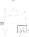
- Fig. 1 shows a schematic representation of a displacer unit according to the invention, for example an axial piston machine, in which the section around a suction port 4 of the displacer unit 1 is executed in detail.
- a check valve 3 is arranged in the housing 2 of the displacer unit 1.
- a fluid flows through the suction port 4 into the interior of the displacer unit 1, that is to say it is sucked in by the engine (not shown).
- the engine is driven by a mechanical coupling with an internal combustion engine, not shown. Due to the suction of the engine crazy check valve 3 in its open position and allows a flow connection between a reservoir and the engine.
- Fig. 2 shows an enlarged view of the displacer unit 1 in the region of the suction port 4.
- the housing 2 in this case has a suction port 4 and a second port 7, both of which are each designed to guide a fluid in the direction of the engine of the displacer unit 1.
- the inflow of a fluid into the second port 7 and an outflow from the suction port 4 is prevented by the check valve 3. Therefore, a fluid flowing into the second port 7 is supplied to the engine of the displacer unit 1.
- the flow path of the suction port 4 and the flow path of the second port 7 merge downstream to a common flow path 8, via which a flow connection to the engine is made.
- the check valve 3 is displaceably mounted in a recess, so that passes in a coming from the direction of the engine or the second port 7 pressure of the recoil in a closed position.
- a suction pressure is exerted on the check valve 3 due to the movement of the engine, it moves away from its closed position to its open position and a fluid can flow through the suction port 4 and the fluid flow holes 13 in the direction of the engine.
- a flange plate 6 is arranged on the housing 2 of the displacer unit, which has a suction channel 5. It can be seen that the intake passage 5 reduces its flow cross-section towards the position which can be closed by the check valve.
- the intake channel 5 is provided with a fluid reservoir or a storage tank connected to fluid.
- a flow from the storage tank through the check valve 3 in the direction of the engine then takes place during a pump operation of the displacer unit 1.
- a fluid under high pressure is at the second port 7 flows and used the displacer unit in engine operation.
- the check valve 3 is urged into its closing position to prevent flow of the fluid into the storage tank. Instead, it flows in the direction of the engine, where it causes a movement of the engine, which in turn converts the output shaft of the internal combustion engine, which is mechanically fixed to the engine, in a starting movement.
- Fig. 3 shows the flow-optimized check valve 3 on the tapered surface of the valve piston 16. This comes to the valve seat 9 so in contact with the wall of a flow path that a seal for the fluid takes place.
- the flow path is provided with an optimized Venturi contour shape, which causes a flow rate increase and reduction of vortex formation and thus the lowering of the flow resistance.
- This Venturi contour shape is interrupted only at the valve seat to obtain a satisfactory sealing effect in a closed state of the check valve 3.
- Another O-ring 14 is also circumferentially arranged in the flow path between the protruding into the housing 2 Venturi contour shape.
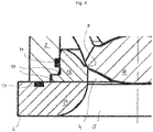
- Fig. 4 shows an enlarged section Fig. 3 In the region of a valve seat 9. This can be seen well the optimized, bevelled contour of the Venturi mold 17, 18, the sealing when placing the valve piston 16 on the valve seat 9 closes.
- the element represented by the reference numeral 19 corresponds to an undercut.
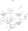
- Fig. 5 is a schematic representation of the hydraulic start-stop system 30.
- One recognizes an internal combustion engine 31, which is coupled via a mechanical coupling 35 with the engine 39 of the displacer unit 1.
- one recognizes the characteristic of the invention within the housing 2 of the displacer unit 1 arranged one-way valve 3, here a check valve.
- the displacer unit 1 is connected at its suction connection 4 to a fluid reservoir 34.
- This fluid reservoir 34 serves as a storage tank for the fluid.
- the displacer unit 1 has a second connection 7, which is designed to guide a fluid in the direction of the engine 39.
- the second connection 7 is connected via a first valve 36 to a pressure accumulator 32 in connection.
- the fluid reservoir 32 is configured to receive a fluid under a high pressure and store it in itself.
- the working hydraulics is in communication.
- a second valve 37 and a third valve 38 communicate with the outlet port 33.
- the third valve 38 may close or open a flow path between the outlet port 33 and the fluid reservoir 34.
- the second valve 37 may close or open a connection to the pressure accumulator 32.
- a first operating state the working hydraulics is supplied with fluid.
- the valves 38, 37 and 36 are in a closed state.
- the displacer unit 1 is driven by the diesel engine 31.
- the displacer unit 1 sucks in the working fluid, for example a hydraulic oil, via the check valve 3.
- the check valve 3 is designed so that this results along the passage direction as low as possible pressure drop.
- a certain suction pressure must not be exceeded. As a result of this results in a line limitation by the suction pressure.
- the displacer unit 1 conveys the fluid to the valve spool located in the working hydraulics.
- the displacer unit 1 is subjected to a load-sensing control, which ensures that the displacer unit 1 adapts the delivery volume flow in accordance with a volumetric flow demand. In an axial piston machine, this is done by adjusting the skew angle.
- FIG. 5 Another operating state of the in the FIG. 5 shown system loads the pressure accumulator 32.
- the valves 38 and 36 are closed.
- the valve 37 is in its open position.
- the conveyed by the displacer unit 1 fluid is conveyed into the pressure accumulator 32.
- the suction channel 7 of the displacer unit 1 is thus under pressure and the displacer unit 1 operates by motor.
- the powertrain is accelerated, thereby exceeding the starting engine speed, which immediately tows the engine started up to its operating speed. Since the valve 38 is opened, the fluid from the working port 33 of the displacer unit 1 returns to the collecting tank 34. During this starting operation, the working hydraulics can not be supplied with hydraulic power.
- the hydraulic start-stop system described above is particularly suitable for use in a mobile work machine. It is possible that the working machine in which, if necessary, drives one or more hydraulic displacement units on the internal combustion engine via a pump distributor gearbox. It is possible that the output power of the internal combustion engine is converted by means of adjustable displacement unit in hydraulic power. It should be noted that the at least one displacement unit is mechanically connected to the internal combustion engine at all times. Furthermore, it can be provided that the at least one displacement unit via a spool the working hydraulics of the mobile working machine, such as. a stem cylinder, a bucket cylinder, a boom cylinder and a drive supplied. Typical applications would be, for example, wheeled excavators, crawler excavators, mobile cranes, etc.
- the use of the hydraulic start-stop functionality is only to be used when the operating temperature of the drive system has been reached, i. H.
- a shutdown of the prime mover should take place only when the operating temperature, in particular that of the engine oil. In a mobile work machine, this not only concerns the operating temperature of the internal combustion engine, but also the hydraulic oil.
- a shutdown of the internal combustion engine is suppressed due to a not yet fully charged pressure accumulator, the shutdown of the engine should not take place until the pressure accumulator is already fully charged, but which are taken into account due to the rotating masses in the drive system (flywheel, gearwheels in the pump transfer case) and the removable energy portion are fed to the pressure accumulator, instead of continuing to load it under continuous fuel consumption.
- the remaining rotational energy is used at the flywheel of the internal combustion engine or a separate speed sensor.
- the present in the accumulator hydraulic oil temperature and the pressure present in the accumulator pressure are measured and taken into account.
- these three variables are read. From this, the time is determined at which, taking into account the losses, sufficient rotational energy for completely charging the pressure accumulator is present.
- the requested shutdown of the internal combustion engine is released. The calculation is based on a stored in the control unit map with the input variables: speed, oil temperature, pressure level in the memory. This results in the energy that can be supplied to the memory to the standstill of the drive. The characteristic is defined for each drive configuration by the results of functional tests.
- hydraulic start-stop system can assist the electric starting operation.
- a torque application of the drive train with the aid of the displacer unit is particularly advantageous when - based on the design of the internal combustion engine as a diesel engine at least accelerated to its starting speed and advantageously to its working speed in the range of 1200 min -1 to 2200 min -1 , preferably 1400 min -1 to 1900 min -1, more preferably 1500 min -1 to 1800 min -1 .
- a torque application of the drive train with the aid of the displacer unit of an internal combustion engine operated in downspeeding mode at least to its starting rotational speed can likewise be undertaken.
- a working speed in the range of 1200 min -1 to 1500 min -1 is preferred. If the speed were to be lowered further, the hydraulic pumps needed to convert mechanical to hydraulic power would have a correspondingly large design. That would be uneconomical.
- the output torque is almost proportional to the swivel angle of the swashplate of an axial piston machine, with the quasi-constant high pressure.
- a hydraulic accumulator in particular a bladder accumulator or a piston accumulator can be used.
- the maximum pressure level in the pressure accumulator is between 100 and 450 bar, preferably 150 to 300 bar and especially at 200 bar.
- the pressure accumulator can be loaded directly via a displacement unit coupled to the internal combustion engine at the power take-off with a fixed ratio.
- the pressure accumulator charging displacer unit can also be located on the primary side of the pump distributor gearbox.
- the pressure accumulator charging displacer unit can also be located on the secondary side of the pump distributor gearbox.
- the pressure accumulator charging displacer unit can be provided exclusively for charging the pressure accumulator.
- the pressure accumulator charging displacer unit can be provided for charging the pressure accumulator and for the operation of at least one secondary consumer. In this case, it is possible that the relevant displacement unit in a certain time interval a) only charges the accumulator, b) is used only for operating the at least one secondary consumer or c) supplies the pressure accumulator and simultaneously at least one secondary consumer.
- the pressure accumulator charging displacer unit may be provided for charging the pressure accumulator and for the operation of at least one main consumer, eg. B. the traction drive.
- the displacer unit in question in a certain time interval a) only charges the accumulator, b) is used only for operating the at least one main consumer or c) supplies the pressure accumulator and simultaneously at least one main consumer.
- the displacer unit charging the pressure accumulator may be identical to the displacer unit that tows up to start the internal combustion engine.
- the pressure accumulator charging displacer unit may be other than the one displacer unit which takes over the same when starting the internal combustion engine.
- Warp-free starting of the internal combustion engine immediately after a torque request or a work request by the driver requires a high torque to accelerate the drive train in a short time.
- a hydraulic starting operation of the proposed system or the availability of a working function of the mobile work machine is faster than in today's electrical starting systems.
- the primary function is the translational movement of the mobile working machine and the operation of the working hydraulics.
- the secondary functions such as (for example, the operation of the air conditioning system, the lighting should preferably be fed from the conventional electrical system during stop operation by secondary consumers to be satisfied.
- the invention enables an increase in comfort and safety due to temporary lower noise pollution at the place of use during the shutdown of the internal combustion engine.
- the loading of the accumulator is also by Rekuperations aber z. B. possible during braking.
- the loading of the memory is also possible by a load point increase.
- the target output power of the internal combustion engine is deliberately chosen to be higher than the required drive power. With the "excess" power, the pressure accumulator is charged.
- the invention also allows an active boost for a short-term power increase provided to the drive. Also, it can be a protection against the stalling of the internal combustion engine obtained.
Landscapes
- Engineering & Computer Science (AREA)
- Mechanical Engineering (AREA)
- General Engineering & Computer Science (AREA)
- Chemical & Material Sciences (AREA)
- Combustion & Propulsion (AREA)
- Fluid-Pressure Circuits (AREA)
- Valve Device For Special Equipments (AREA)
Abstract
Description
- Die vorliegende Erfindung betrifft eine Verdrängereinheit sowie ein hydraulisches Start-Stopp-System mit einer solchen Verdrängereinheit.
- Es ist bekannt, dass mobile Arbeitsmaschinen hydraulische Vorrichtungen aufweisen und diese zum Ausführen einer Arbeitstätigkeit genutzt werden können. Dabei umfasst das hydraulische Antriebssystem eine vorzugsweise im Fördervolumen steuerbare bzw. regelbare Hydraulikpumpe, die typischerweise mit einem als Brennkraftmaschine ausgebildeten Primärantrieb mechanisch gekoppelt ist. Die Brennkraftmaschine umfasst dabei in der Regel einen Elektrostarter zum Starten der Brennkraftmaschine, der durch eine Batterie gespeist wird. Diese Batterie wird dabei durch einen von der Brennkraftmaschine angetriebenen Generator geladen.
- Im Stand der Technik ist es bekannt, eine Brennkraftmaschine, insbesondere einen Dieselmotor, durch elektrische Starteranlagen, durch elektrische Startergeneratoren, die eine Vereinigung von Starteranlage und Generator in einem Bauteil darstellen, und durch hydraulische Start-Stopp-Systeme anzulassen. Bei einem Anlassvorgang einer Brennkraftmaschine ist es erforderlich, deren Ausgangswelle rotieren zu lassen, um die Arbeitstakte eines in der Brennkraftmaschine angeordneten Kolbens auszuführen.
- Der Stand der Technik sieht hierzu ein hydraulisches Start-Stopp-System vor, bei dem eine mechanisch mit einer Brennkraftmaschine gekoppelte Verdrängereinheit nicht nur durch die Brennkraftmaschine im "Pumpenbetrieb" angesteuert wird, sondern ein Anlassen der Brennkraftmaschine durch Nutzung der Verdrängereinheit im "Motorenbetrieb". Wird für die Arbeitshydraulik hydraulische Leistung benötigt, wird die Verdrängereinheit mit Hilfe der mechanischen Kopplung zu der Brennkraftmaschine angetrieben und saugt aus einem Fluidreservoir ein Fluid, typischerweise ein Öl oder dergleichen, an und gibt dies auf der Hochdruckseite an die Arbeitshydraulik weiter. Dadurch ist es der Arbeitshydraulik beispielsweise möglich, einen Baggerarm zu verfahren oder das Schild einer Raupe anzuheben.
- Im "Motorbetrieb" ist vorgesehen, dass eine gestoppte Brennkraftmaschine mit Hilfe der Verdrängereinheit angelassen wird. Dazu wird an die Einlassöffnung der Verdrängereinheit, die ein Fluid in Richtung ihres Triebwerks, das eine hydraulische Leistung in eine rotatorische Leistung wandeln kann, eine sich aufzweigende Leitung angeschlossen, die an einem ihrer Enden mit einem Fluidreservoir über ein Einwegventil in Verbindung steht und mit dem anderen ihrer Enden über ein schaltbares Ventil mit einem Druckspeicher in Verbindung steht. Weist der Druckspeicher eine ausreichende Menge an unter Druck stehendem Fluid auf, so kann dieses Fluid dazu genutzt werden, eine stillstehende Brennkraftmaschine anzulassen. Dazu wird das im Pfad zwischen dem Druckspeicher und dem Triebwerk der Verdrängereinheit angeordnete absperrbare Ventil geöffnet, um ein Einströmen des unter Druck stehenden Fluids in die Verdrängereinheit zu ermöglichen.
- Erreicht das unter Druck stehende Fluid das Triebwerk, führt dies zu einer Rotation der mit der Verdrängereinheit gekoppelten Ausgangswelle der Brennkraftmaschine. Diese beim Anlassen einer Brennkraftmaschine notwendige Rotation der Ausgangswelle ersetzt dabei die typische Tätigkeit einer elektrischen Starter-Anlage.
- Es ist das Ziel der vorliegenden Erfindung eine für das hydraulische Start-Stopp-System geeignete Verdrängereinheit in vorteilhafter Weise weiterzubilden.
- Die erfindungemäße Verdrängereinheit, die insbesondere eine Axialkolbenmaschine darstellen kann, umfasst ein Gehäuse, ein Triebwerk zum Wandeln der rotatorischen Leistung in eine hydraulische Leistung und einen Sauganschluss zum Zuführen eines Fluids an das Triebwerk. Die Verdrängereinheit ist durch ein Einwegventil gekennzeichnet, das im Gehäuse der Verdrängereinheit angeordnet ist.
- Die Anordnung des Einwegventils in dem Gehäuse der Verdrängereinheit führt zu einer Verringerung des Strömungswiderstands zwischen dem Hydrauliköl-Vorratstank (auch: Fluidreservoir) und dem im Pumpenbetrieb arbeitenden Triebwerk der Verdrängereinheit. Ein niedrigerer Gesamtströmungswiderstand sorgt für eine höhere Sauggrenzdrehzahl, die einen Betriebszustand einer Pumpe charakterisiert, bei dem in einem Saughub aufgrund einer Vakuumbildung ein Füllungsmangel auftritt, der zu einer Verminderung des Förderstroms der Pumpe und zu einer Schädigung der Pumpe durch Kavitationserosion im anschließenden Förderhub führen kann. Für eine hohe Sauggrenzdrehzahl ist es von Vorteil, den Strömungswiderstand möglichst gering zu halten.
- Da sich der Gesamtströmungswiderstand zwischen dem Hydrauliköl-Vorratstank (auch: Fluidreservoir) und dem Triebwerk der Verdrängereinheit aus der Zuleitung vom Vorratstank bis zum Einwegventil und der Zuleitung vom Einwegventil bis zum Triebwerk ergibt, sinkt der Gesamtströmungswiderstand, wenn sich der Abschnitt des höchsten Strömungswiderstands, der Bereich um das Einwegventil, in der Nähe des Triebwerks angeordnet ist. Dies ist darin begründet, da sich der Querschnitt des Ansaugkanals vom Sauganschluss der Verdrängereinheit zum Triebwerk hin typischerweise verkleinert. Es kann dann bei gleichbleibendem Druckabfall (bzw. Strömungswiderstand) der Durchlassquerschnitt des Rückschlagventils umso kleiner ausgeführt werden, je näher sich dieses am Triebwerk befindet. Zudem ist ein geometrisch kleiner ausgeführtes Rückschlagventil kostengünstiger zu realisieren und erfordert weniger Einbauraum. Daher lassen sich zu dem im Stand der Technik typischerweise außerhalb des Gehäuses der Verdrängereinheit angeordneten Rückschlagventile (auch: Einwegventile) die vorstehend aufgeführten positiven Effekte erreichen.
- Darüber hinaus liegt bei einer motorischen Nutzung der Verdrängereinheit zwischen dem Triebwerk und dem zum Einwegventil ein Hochdruckniveau des Fluids vor. Hieraus folgt, dass die Ölverbindung zwischen diesen beiden Bauteilen hochdruckdicht sein muss. Wäre das Einwegventil außerhalb des Gehäuses der Verdrängereinheit angeordnet, müsste der entsprechende Hydraulikschlauch die Hochdruckbelastung aushalten. Nach der erfindungsgemäßen Verdrängereinheit, bei der das Einwegventil im Gehäuse selbst angeordnet ist, muss ein an den Sauganschluss der Verdrängereinheit geführter Hydraulikschlauch lediglich den Niederdruck aushalten können.
- Nach einer optionalen Modifikation der Erfindung ist das Einwegventil im Strömungspfad zwischen Sauganschluss und Triebwerk angeordnet.
- Vorzugsweise ist das Einwegventil im Gehäuse der Verdrängereinheit integriert.
- Nach einer weiteren Modifikation der Erfindung ist es möglich, dass das Einwegventil in einem Ansaugkanal einer Anschlussplatte der Verdrängereinheit angeordnet ist oder mit der Anschlussplatte zusammenwirkt.
- Nach einer bevorzugten Variation der Erfindung verkleinert sich der Querschnitt des Strömungspfads vom Sauganschluss in Richtung Triebwerk, vorzugsweise erfolgt diese Verkleinerung kontinuierlich und das Einwegventil ist an einer Position in dem Strömungspfad angeordnet, an dem der Querschnitt des Strömungskanals nicht maximal ist.
- Vorzugsweise ist das Einwegventil im Strömungspfad vom Sauganschluss beabstandet in Richtung Triebwerk angeordnet.
- Nach einer optionalen Modifikation der Erfindung ist das Einwegventil dazu ausgelegt, das Fluid nur in Richtung Triebwerk strömen zu lassen und eine Strömung des Fluids in entgegengesetzte Richtung zu minimieren oder zu unterbinden.
- Nach einer Fortbildung der Erfindung ist das Einwegventil ein Rückschlagventil oder ein Schieberventil, vorzugsweise ein hochdruckbetätigbares Schieberventil.
- Nach einer Fortbildung der Erfindung umfasst die Verdrängereinheit ferner einen zweiten Anschluss zum Zuführen eines Fluids an das Triebwerk, wobei die vom ersten Sauganschluss und vom zweiten Anschluss ausgehenden Strömungspfade sich zu einem gemeinsamen Strömungspfad vereinigen und das Einwegventil im Bereich zwischen erstem Sauganschluss und dem vereinigten gemeinsamen Strömungspfad angeordnet ist.
- Durch das Vorsehen des zweiten Anschlusses zum Zuführen eines Fluids an das Triebwerk eignet sich die Verdrängereinheit besonders für den Einsatz in einem hydraulischen Start-Stopp-System. Wie bereits im einleitenden Teil der Beschreibung erläutert, wird für ein Anlassen einer mit der Verdrängereinheit mechanisch gekoppelten Brennkraftmaschine nicht der Pumpenbetrieb sondern der Motorbertrieb verwendet. Dafür wird ein in einem Druckspeicher unter Druck gespeichertes Fluid dem Triebwerk zugeführt. Um ein Strömen des unter Druck stehenden Fluids in den Vorratstank zu unterbinden ist das Einwegventil vorgesehen. Das Einströmen eines Fluids an dem zweiten Anschluss und das Ausströmen aus dem ersten Sauganschluss ist damit nicht möglich.
- Nach einer bevorzugten Ausführungsform der Erfindung ist das Einwegventil strömungsoptimiert und wirkt mit einem strömungsoptimierten Ventilsitz zusammen. Ein strömungsoptimiertes Einwegventil sowie ein strömungsoptimierter Ventilsitz minimieren die Wirbelbildung bei einer Fluideinströmung entlang einer Fluiddurchtrittsöffnung an dem Sauganschluss.
- Vorzugsweise ist der durch das Einwegventil verschließbare Strömungspfad eine Venturi-Kontur, die durch das Einwegventil im Punkt eines geringsten Strömungsquerschnitts im Bereich des Ventils verschließbar ist.
- Beim Einströmen des Fluids, z.B. einem Hydrauliköl, in die im Pumpenbetrieb arbeitende Verdrängereinheit erreicht man an dem Punkt des geringsten Strömungsquerschnitts die maximale Strömungsgeschwindigkeit, was einen für den Pumpenbetrieb unterstützenden Saugeffekt hervorruft.
- Nach einer weiteren Fortbildung der Erfindung weist die Venturi-Kontur einen optimierten Krümmungsverlauf auf, um eine Wirbelbildung eines durch das Einwegventil strömenden Fluids zu minimieren.
- Vorzugsweise ist der Sauganschluss mit einer Flanschplatte verbindbar, die als ein Teil einer mit dem Strömungspfad des Sauganschlusses gebildeten Venturi-Kontur ausgeführt ist.
- Die Erfindung betrifft ferner ein hydraulisches Start-Stopp-System, das eine Verdrängereinheit nach einer der vorhergehend dargestellten Varianten umfasst.
- Vorzugsweise umfasst das hydraulische Start-Stopp-System ferner eine Brennkraftmaschine, die mit der Verdrängereinheit mechanisch gekoppelt ist und dazu ausgelegt ist, die Verdrängereinheit anzutreiben und von der Verdrängereinheit angetrieben zu werden, und einen Druckspeicher, der mit einem Auslassanschluss der Verdrängereinheit und mit einem zweiten Anschluss zum Zuführen eines Fluids an das Triebwerk der Verdrängereinheit verbunden ist, wobei der erste Sauganschluss mit einem Fluidreservoir verbunden ist.
- Nach einer optionalen Modifikation des hydraulischen Start-Stopp-Systems wird ein unter Druck stehendes Fluid in dem Fluidspeicher dazu genutzt, eine Brennkraftmaschine zu starten, in dem ein aus dem Fluidspeicher strömendes Fluid die Verdrängereinheit antreibt und über die mechanische Kopplung zwischen Verdrängereinheit und Brennkraftmaschine eine Anlassbewegung für die Brennkraftmaschine ausübt, wobei vorzugsweise zum Leiten des Fluids ein erstes Ventil zwischen Fluidspeicher und zweitem Anschluss und ein zweites Ventil zwischen dem Auslassanschluss und einer Verbindung zu dem Fluidreservoir vorgesehen sind.
- Ferner betrifft die vorliegende Erfindung auch eine Mobile Arbeitsmaschine, insbesondere einen Mobilbagger, einen Raupenbagger, einen Mobilkran, mit einem hydraulischen Start-Stopp-System nach einer der vorstehend beschriebenen Varianten.
- Weitere Merkmale, Einzelheiten und Vorteile der Erfindung werden anhand der detaillierten Diskussion der nachfolgenden Figuren ersichtlich.
- Dabei zeigen:
- Fig. 1:
- eine schematische Darstellung einer erfindungsgemäßen Verdrängereinheit mit einem integrierten Rückschlagventil,
- Fig. 2:
- eine schematische Darstellung eines Teils der erfindungsgemäßen Verdrängereinheit,
- Fig. 3:
- eine schematische Darstellung der erfindungsgemäßen Verdrängereinheit nach einer weiteren Ausführungsform,
- Fig. 4:
- eine vergrößerte Detailsansicht der weiteren Ausführungsform, und
- Fig. 5:
- einen Schaltplan für ein hydraulisches Start-Stopp-System nach der Erfindung.
-
Fig. 1 zeigt eine schematische Darstellung einer erfindungsgemäßen Verdrängereinheit, beispielsweise eine Axialkolbenmaschine, bei der der Abschnitt um einen Sauganschluss 4 der Verdrängereinheit 1 detailliert ausgeführt ist. Man erkennt, dass ein Rückschlagventil 3 im Gehäuse 2 der Verdrängereinheit 1 angeordnet ist. Im regulären Pumpenbetrieb der Verdrängereinheit 1 strömt ein Fluid durch den Sauganschluss 4 in das Innere der Verdrängereinheit 1, wird also von dem Triebwerk (nicht dargestellt) angesaugt. Das Triebwerk wird über eine mechanische Kopplung mit einer nicht dargestellten Brennkraftmaschine angetrieben. Durch die Saugwirkung des Triebwerks verrückt das Rückschlagventil 3 in seine Offenstellung und ermöglicht eine Strömungsverbindung zwischen einem Vorratsreservoir und dem Triebwerk. -
Fig. 2 zeigt eine vergrößerte Darstellung der Verdrängereinheit 1 im Bereich des Sauganschlusses 4. Das Gehäuse 2 weist dabei einen Sauganschluss 4 und einen zweiten Anschluss 7 auf, die beide jeweils dazu ausgelegt sind, ein Fluid in Richtung des Triebwerks der Verdrängereinheit 1 zu führen. Das Einströmen eines Fluids in den zweiten Anschluss 7 und ein Herausströmen aus dem Sauganschluss 4 wird durch das Rückschlagventil 3 unterbunden. Daher wird ein in den zweiten Anschluss 7 strömendes Fluid dem Triebwerk der Verdrängereinheit 1 zugeführt. Der Strömungspfad des Sauganschlusses 4 und der Strömungspfad des zweiten Anschlusses 7 vereinigen sich stromabwärts zu einem gemeinsamen Strömungspfad 8, über den eine Strömungsverbindung zu dem Triebwerk hergestellt wird. - Das Rückschlagventil 3 ist dabei verschieblich in einer Ausnehmung gelagert, sodass bei einem aus Richtung des Triebwerks oder des zweiten Anschlusses 7 stammenden Drucks des Rückschlags in eine geschlossene Position übergeht. Wird jedoch aufgrund der Bewegung des Triebwerks ein Saugdruck auf das Rückschlagventil 3 ausgeübt, so bewegt es sich weg von seiner Schließstellung in seine Offenstellung und ein Fluid kann durch den Sauganschluss 4 und die Fluiddurchflussbohrungen 13 in Richtung des Triebwerks strömen. Ferner erkennt man, dass eine Flanschplatte 6 an dem Gehäuse 2 der Verdrängereinheit angeordnet ist, die einen Ansaugkanal 5 aufweist. Man erkennt, dass der Ansaugkanal 5 seinen Strömungsquerschnitt hin zu der Position, die durch das Rückschlagventil verschließbar ist, verkleinert. Verwendet man die so ausgebildete Verdrängereinheit 1 in einem hydraulischen Start-Stopp-System, so ist der Ansaugkanal 5 mit einem Fluidreservoir bzw. einem Vorratstank an Fluid verbunden. Eine Strömung von dem Vorratstank durch das Rückschlagventil 3 in Richtung des Triebwerks erfolgt dann bei einem Pumpenbetrieb der Verdrängereinheit 1. Wird die Verdrängereinheit 1 jedoch dazu genutzt, eine Brennkraftmaschine anzulassen oder bei einem Anlassvorgang zu unterstützen, wird ein unter einem großen Druck stehendes Fluid an dem zweiten Anschluss 7 angeströmt und die Verdrängereinheit im Motorbetrieb genutzt. Durch das an dem zweiten Anschluss 7 einströmende Fluid wird das Rückschlagventil 3 in seine schließende Position gedrängt, um ein Strömen des Fluids in den Vorratstank zu unterbinden. Stattdessen strömt es in Richtung des Triebwerks, wo es eine Bewegung des Triebwerks hervorruft, die wiederum die Ausgangswelle der Brennkraftmaschine, die mechanisch fest mit dem Triebwerk gekoppelt ist, in eine Anlassbewegung überführt.
-
Fig. 3 zeigt eine strömungsoptimierte Darstellung des Rückschlagventils 3 sowie einen Strömungsoptimierten Ventilsitz 9. Man erkennt das strömungsoptimierte Rückschlagventil 3 an der abgeschrägten Fläche des Ventilkolbens 16. Dieser kommt an den Ventilsitz 9 derart mit der Wandung eines Strömungspfads in Kontakt, dass eine Abdichtung für das Fluid erfolgt. Dabei ist der Strömungspfad mit einer optimierten Venturi-Konturform versehen, die eine Strömungsgeschwindigkeitserhöhung sowie Verminderung von Wirbelbildungen und damit das Absenken des Strömungswiderstands erwirkt. Diese Venturi-Konturform ist lediglich am Ventilsitz unterbrochen, um eine zufriedenstellende Dichtwirkung in einem geschlossenen Zustand des Rückschlagventils 3 zu erhalten. Zudem erkennt man, dass es im Übergangsbereich der Flanschplatte 6 zu dem Gehäuse 2 einen O-Ring 14 gibt, um Dichtheit zu erlangen. Ein weiterer O-Ring 14 ist auch umfangseitig in dem Strömungspfad zwischen der in das Gehäuse 2 hineinragenden Venturi-Konturform angeordnet. -
Fig. 4 zeigt einen vergrößerten Ausschnitt ausFig. 3 im Bereich eines Ventilsitzes 9. Hieran erkennt man gut die optimierte, abgeschrägte Kontur der Venturi-Form 17, 18, die beim Aufsetzen des Ventilkolbens 16 auf dem Ventilsitz 9 dichtend schließt. Das mit dem Bezugszeichen 19 dargestellte Element entspricht dabei einem Freistich. -
Fig. 5 ist eine schematische Darstellung des hydraulischen Start-Stopp-Systems 30. Man erkennt eine Brennkraftmaschine 31, die über eine mechanische Kopplung 35 mit dem Triebwerk 39 der Verdrängereinheit 1 gekoppelt ist. Zudem erkennt man das für die Erfindung charakteristisch innerhalb des Gehäuses 2 der Verdrängereinheit 1 angeordnete Einwegventil 3, hier ein Rückschlagventil. Ferner ist die Verdrängereinheit 1 an ihrem Sauganschluss 4 mit einem Fluidreservoir 34 verbunden. Dieses Fluidreservoir 34 dient als Vorratstank für das Fluid. - Darüber hinaus weist die Verdrängereinheit 1 einen zweiten Anschluss 7 auf, der dazu ausgelegt ist, ein Fluid in Richtung des Triebwerks 39 zu führen. Der zweite Anschluss 7 ist dabei über ein erstes Ventil 36 mit einem Druckspeicher 32 in Verbindung. Der Fluidspeicher 32 ist dazu ausgelegt, ein Fluid unter einem hohen Druck aufzunehmen und dieses in sich zu speichern. Am Auslassanschluss 33 der Verdrängereinheit 1 steht die Arbeitshydraulik in Verbindung. Ferner steht mit dem Auslassanschluss 33 ein zweites Ventil 37 und ein drittes Ventil 38 in Verbindung. Das dritte Ventil 38 kann einen Strömungspfad zwischen dem Auslassanschluss 33 und dem Fluidreservoir 34 schließen oder öffnen. Das zweite Ventil 37 kann eine Verbindung zu dem Druckspeicher 32 schließen oder öffnen.
- Das in
Fig. 5 dargestellte System wird anhand der verschiedenen Betriebszustände, die das System einnehmen kann, erläutert. In einem ersten Betriebszustand wird die Arbeitshydraulik mit Fluid versorgt. Dies entspricht einem Normalbetrieb. Hierin sind die Ventile 38, 37 und 36 in einem geschlossenen Zustand. Im Normalbetrieb wird die Verdrängereinheit 1 vom Dieselmotor 31 angetrieben. Dabei saugt die Verdrängereinheit 1 das Arbeitsfluid, beispielsweise ein Hydrauliköl, über das Rückschlagventil 3 an. Das Rückschlagventil 3 ist dabei so ausgeführt, dass sich hierüber entlang der Durchlassrichtung ein möglichst geringer Druckabfall ergibt. Je nach Volumenstrom, d.h. Drehzahl und Verdrängervolumen der Verdrängereinheit 1 darf ein bestimmter Ansaugdruck nicht unterschritten werden. Als Folge hieraus ergibt sich eine Leitungsbegrenzung durch den Ansaugdruck. Aus dem Auslassanschluss 33 (auch: Arbeitsanschluss) fördert die Verdrängereinheit 1 das Fluid an dem sich in der Arbeitshydraulik befindenden Ventilschieber. Die Verdrängereinheit 1 ist dabei einer Load-Sensing-Regelung unterzogen, die dafür sorgt, dass die Verdrängereinheit 1 entsprechend einer Volumenstromanforderung den Fördervolumenstrom anpasst. Bei einer Axialkolbenmaschine geschieht dies durch Anpassen des Schrägwinkels. - Ein weiterer Betriebszustand des in der
Figur 5 dargestellten Systems lädt den Druckspeicher 32. In diesem Zustand sind die Ventile 38 und 36 geschlossen. Das Ventil 37 ist in seiner offenen Position. Zum Laden des Druckspeichers 32, der auch als Hydrospeicher ausgeführt sein kann, wird das von der Verdrängereinheit 1 geförderte Fluid in den Druckspeicher 32 gefördert. - Als weiteren Betriebszustand kann man das Starten des Dieselmotors ansehen. Um den Dieselmotor starten zu können, muss dieser in einem gestoppten Zustand sein. Dann sind alle Ventile 36, 37 und 38 zu schließen. Ferner muss der hydraulische Druckspeicher 32 bei abgeschalteten Dieselmotor 31 ausreichend geladen sein, um eine Startanforderung erfüllen zu können. Zur Einleitung des Startvorgangs werden die Ventile 36 und 38 geöffnet, wohingegen das Ventil 37 geschlossen bleibt. Das unter Druck stehende Fluid gelangt vom Druckspeicher 32 über den zweiten Anschluss 7 an den Saugkanal der Verdrängereinheit 1. Dabei schließt das Rückschlagventil 3 entsprechend dem dort anliegendem Druckverhältnis die Verbindung zwischen dem Druckspeicher 32 und dem Sammeltank 34 des Fluids. Der Ansaugkanal 7 der Verdrängereinheit 1 steht somit unter Druck und die Verdrängereinheit 1 arbeitet motorisch. Der Antriebsstrang wird beschleunigt, wodurch die Startdrehzahl des Motors überschritten wird, wodurch unmittelbar nachfolgend der gestartete Motor auf seine Betriebsdrehzahl hochgeschleppt wird. Da das Ventil 38 geöffnet ist, gelangt das Fluid vom Arbeitsanschluss 33 der Verdrängereinheit 1 zurück in den Sammeltank 34. Während dieses Startvorgangs kann die Arbeitshydraulik nicht mit hydraulischer Leistung versorgt werden.
- Das vorstehend beschriebene hydraulische Start-Stopp-System eignet sich besonders für den Einsatz in einer Mobilen Arbeitsmaschine. Dabei ist es möglich, dass die Arbeitsmaschine, bei der an der Brennkraftmaschine gegebenenfalls über ein Pumpenverteilergetriebe ein oder mehrere hydraulische Verdrängereinheiten antreibt. Dabei ist es möglich, dass die abgegebene Leistung der Brennkraftmaschine mittels verstellbarer Verdrängereinheit in hydraulische Leistung umgesetzt wird. Es ist zu beachten, dass die mindestens eine Verdrängereinheit jederzeit mechanisch mit der Brennkraftmaschineverbunden ist. Ferner kann vorgesehen sein, dass die mindestens eine Verdrängereinheit über einen Steuerschieber die Arbeitshydraulik der Mobilen Arbeitsmaschine, wie z.B. einen Stielzylinder, einen Löffelzylinder, einen Auslegerzylinder und einen Fahrantrieb versorgt. Typische Anwendungen wären beispielsweise Mobilbagger, Raupenbagger, Mobilkräne etc.
- Vorzugsweise ist die Nutzung der hydraulischen Start-Stopp-Funktionalität erst bei der Erreichung der Betriebstemperatur des Antriebssystems einzusetzen, d. h. wie bei PKW-Start-Stopp-Systemen bekannt, soll eine Abschaltung des Primärantriebs erst bei Erreichung der Betriebstemperatur insbesondere der des Motorenöls erfolgen. In einer Mobilen Arbeitsmaschine betrifft das nicht nur die Betriebstemperatur der Brennkraftmaschine, sondern auch das Hydrauliköl.
- Das zum Starten notwendige Hochschleppen der Brennkraftmaschine soll sowohl bei einem Kaltstart als auch bei einem Warmstart bevorzugt immer mit dem hydraulischen System erfolgen. Damit Letzteres möglich ist, soll eine Abschaltung der Brennkraftmaschine nur dann erfolgen und ggf. solange verzögert werden bis der hydraulische Druckspeicher voll aufgeladen ist. Dabei gibt es zwei Ausnahmen, wobei die erste das Detektieren eines Not-Aus ist und die zweite das Detektieren einer Undichtheit des Druckspeichers und der nur für den Speicherbetrieb vorhandenen Hydraulikleitung.
- Wird ein Abschalten der Brennkraftmaschine aufgrund eines noch nicht voll aufgeladenen Druckspeichers unterdrückt, soll die Abschaltung der Brennkraftmaschine nicht erst dann erfolgen, wenn der Druckspeicher bereits voll aufgeladen ist, sondern die aufgrund der im Antriebssystem rotierenden Massen (Schwungrad, Zahnräder im Pumpenverteilergetriebe) berücksichtigt werden und der daraus entnehmbare Energieanteil dem Druckspeicher zugeführt werden, anstatt diesen weiterhin unter fortdauerndem Kraftstoffverbrauch zu laden.
- Zur Bestimmung der noch vorhandenen Rotationsenergie dient der am Schwungrad der Brennkraftmaschine vorhandene oder ein separater Drehzahlsensor. Zur Berücksichtigung des Anteils der Rotationsenergie, die dem Druckspeicher zugeführt werden kann, werden die im Druckspeicher vorliegende Hydrauliköltemperatur und der im Druckspeicher vorliegende Druck gemessen und berücksichtigt. In einem Steuergerät werden diese drei Grössen eingelesen. Daraus wird der Zeitpunkt bestimmt an dem unter Berücksichtigung der Verluste genügend Rotationsenergie zur vollständigen Aufladung des Druckspeichers vorliegt. Zu diesem Zeitpunkt wird die angeforderte Abschaltung der Brennkraftmaschine freigegeben. Die Berechnung erfolgt anhand einem im Steuergerät hinterlegten Kennfeld mit den Eingangsgrössen: Drehzahl, Öltemperatur, Druckniveau im Speicher. Hieraus ergibt sich die Energie, die dem Speicher bis zum Stillstand des Antriebs zugeführt werden kann. Die Kennlinie wird für jede Antriebskonfiguration durch die Ergebnisse von Funktionsversuchen definiert.
- Zudem ist denkbar, dass konventionelle Starteinrichtung nach wie vor als Back-Up für Warmstarts und für "Kaltstarts" zur Verfügung stehen.
- Weiter kann das hydraulische Start-Stopp-System den elektrischen Startvorgang unterstützen.
- Eine Drehmomentbeaufschlagung des Antriebstranges mit Hilfe der Verdrängereinheit ist besonders vorteilhaft, wenn man - bezogen auf die Ausführung der Brennkraftmaschine als Dieselmotor mindestens auf seine Startdrehzahl beschleunigt und vorteilhafterweise auf seine Arbeitsdrehzahl im Bereich von 1200 min-1 bis 2200 min-1, bevorzugt von 1400 min-1 bis 1900 min-1 besonders bevorzugt auf 1500 min-1 bis 1800 min-1.
- Eine Drehmomentbeaufschlagung des Antriebstranges mit Hilfe der Verdrängereinheit einer im Downspeeding-Modus betriebenen Brennkraftmaschine mindestens auf ihre Startdrehzahl kann ebenfalls vorgenommen werden. Bezogen auf die Ausführung der Brennkraftmaschine als Dieselmotor ist eine Arbeitsdrehzahl im Bereich von 1200 min-1 bis 1500 min-1 bevorzugt. Bei einer weiteren Absenkung der Drehzahl hätten die zur Umwandlung von mechanischer in hydraulische Leistung benötigten Hydraulikpumpen eine entsprechend grosse Bauform. Das wäre unwirtschaftlich.
- Auch könnte man eine Drehmomentbeaufschlagung des bereits unter Last stehenden Antriebstranges mit Hilfe der Verdrängereinheit vornehmen, um eine Brennkraftmaschine mindestens auf ihre Startdrehzahl zu beschleunigen.
- Bei der zum Hochschleppen der Brennkraftmaschine verwendeten Verdrängereinheit ist bei quasi konstantem Hochdruck das Abtriebsdrehmoment nahezu proportional zum Schwenkwinkel der Schrägscheibe einer Axialkolbenmaschine.
- Als Druckspeicher kann ein Hydrospeicher, insbesondere ein Blasenspeicher oder ein Kolbenspeicher eingesetzt werden.
- Das maximale Druckniveau im Druckspeicher liegt zwischen 100 und 450 bar, bevorzugt 150 bis 300 bar und besonders bei 200 bar.
- Der Druckspeicher kann direkt über eine am Nebenabtrieb mit fester Übersetzung an die Brennkraftmaschine gekoppelten Verdrängereinheit geladen werden. Die den Druckspeicher aufladende Verdrängereinheit kann sich auch auf der Primärseite des Pumpenverteilergetriebes befinden. Die den Druckspeicher aufladende Verdrängereinheit kann sich auch auf der Sekundärseite des Pumpenverteilergetriebes befinden.
- Die den Druckspeicher aufladende Verdrängereinheit kann ausschliesslich zur Aufladung des Druckspeichers vorgesehen sein. Die den Druckspeicher aufladende Verdrängereinheit kann zur Aufladung des Druckspeichers und für den Betrieb mindestens eines Nebenverbrauchers vorgesehen sein. In diesem Fall ist es möglich, dass die betreffende Verdrängereinheit in einem bestimmten Zeitintervall a) nur den Druckspeicher auflädt, b) nur zum Betrieb des mindestens einen Nebenverbrauchers eingesetzt wird oder c) den Druckspeicher und simultan mindestens einen Nebenverbraucher versorgt.
- Die den Druckspeicher aufladende Verdrängereinheit kann zur Aufladung des Druckspeichers vorgesehen sein und für den Betrieb mindestens eines Hauptverbrauchers, z. B. dem Fahrantrieb. In diesem Fall ist es möglich, dass die betreffende Verdrängereinheit in einem bestimmten Zeitintervall a) nur den Druckspeicher auflädt, b) nur zum Betrieb des mindestens einen Hauptverbrauchers eingesetzt wird oder c) den Druckspeicher und simultan mindestens einen Hauptverbraucher versorgt.
- Die den Druckspeicher aufladende Verdrängereinheit kann identisch mit der zum Starten der Brennkraftmaschine hochschleppenden Verdrängereinheit sein. Die den Druckspeicher aufladende Verdrängereinheit kann eine andere sein als diejenige Verdrängereinheit, die beim Starten der Brennkraftmaschine das Hochschleppen desselben übernimmt.
- Verzugsfreies Starten der Brennkraftmaschine unmittelbar nach einer Drehmomentanforderung bzw. einem Arbeitswunsch durch den Fahrer bedingt ein hohes Drehmoment, um den Antriebstrang in kurzer Zeit zu beschleunigen. Als Folge davon ist ein hydraulischer Startvorgang des vorgesehenen Systems bzw. die Verfügbarkeit einer Arbeitsfunktion der Mobilen Arbeitsmaschine schneller als bei den heutigen elektrischen Startsystemen.
- Es lässt sich zudem eine Kraftstoffeinsparung durch Abschalten der Brennkraftmaschineerzielen, wenn keine Leistungsabgabe zur Nutzung der Primärfunktionen erforderlich ist. Als Primärfunktion werden die translatorische Bewegung der Mobilen Arbeitsmaschine und die Betätigung der Arbeitshydraulik bezeichnet. Die im Bedarfsfall während des Stopp-Betriebs weiterhin durch Nebenverbraucher zu erfüllenden Sekundärfunktionen wie (z. B. der Betrieb der Klimaanlage, die Beleuchtung sollen bevorzugt aus dem konventionellen Bordnetz gespeist werden.
- Die Erfindung ermöglicht eine Erhöhung des Komforts und der Sicherheit durch temporäre geringere Lärmbelastung am Einsatzort während der Abschaltung der Brennkraftmaschine.
- Das Laden des Druckspeichers ist auch durch Rekuperationsleistung z. B. bei Bremsvorgängen möglich.
- Das Laden des Speichers ist auch durch eine Lastpunktanhebung möglich. Dabei wird die Sollabgabeleistung der Brennkraftmaschine bewusst höher gewählt als die benötigte Antriebsleistung. Mit der "überschüssigen" Leistung wird der Druckspeicher aufgeladen.
- Auch ist eine Lastpunktabsenkung denkbar. Die Leistungsabgabe der Brennkraftmaschine wird dann kurzzeitig reduziert. Das zur Versorgung der Verbraucher benötigte "Leistungsdefizit" wird aus dem Druckspeicher entnommen.
- Die Erfindung ermöglicht zudem einen Aktiv Boost für eine kurzzeitige dem Antrieb zur Verfügung gestellte Leistungserhöhung. Auch kann damit ein Schutz vor dem Abwürgen der Brennkraftmaschineerhalten werden.
Claims (15)
- Verdrängereinheit (1), insbesondere eine Axialkolbenmaschine, umfassend:ein Gehäuse (2),ein Triebwerk zum Wandeln der rotatorischen Leistung in hydraulische Leistung, undeinen Sauganschluss (4) zum Zuführen eines Fluids an das Triebwerk,gekennzeichnet durchein Einwegventil (3), das im Gehäuse (2) der Verdrängereinheit (1) angeordnet ist.
- Verdrängereinheit (1) nach Anspruch 1, wobei das Einwegventil (3) im Strömungspfad zwischen Sauganschluss (4) und Triebwerk angeordnet ist.
- Verdrängereinheit (1) nach einem der vorhergehenden Ansprüche, wobei das Einwegventil (3) im Gehäuse (2) der Verdrängereinheit (1) integriert ist.
- Verdrängereinheit (1) nach einem der vorhergehenden Ansprüche, wobei das Einwegventil (3) in einem Ansaugkanal (5) einer Anschlussplatte (6) der Verdrängereinheit (1) angeordnet ist.
- Verdrängereinheit (1) nach einem der vorhergehenden Ansprüche, wobei sich der Querschnitt des Strömungspfads vom Sauganschluss (4) in Richtung Triebwerk verkleinert, vorzugsweise kontinuierlich verkleinert, und das Einwegventil (3) an einer Position in dem Strömungspfad angeordnet ist, an dem der Querschnitt des Strömungskanals nicht maximal ist.
- Verdrängereinheit (1) nach einem der vorhergehenden Ansprüche, wobei das Einwegventil (3) im Strömungspfad vom Sauganschluss (4) beabstandet in Richtung Triebwerk angeordnet ist.
- Verdrängereinheit (1) nach einem der vorhergehenden Ansprüche, wobei das Einwegventil (3) dazu ausgelegt ist, das Fluid nur in Richtung Triebwerk strömen zu lassen und eine Strömung des Fluids in entgegengesetzte Richtung zu minimieren oder zu unterbinden.
- Verdrängereinheit (1) nach einem der vorhergehenden Ansprüche, wobei das Einwegventil (3) ein Rückschlagventil oder ein Schieberventil, vorzugsweise ein hochdruckbetätigbares Rückschlagventil ist.
- Verdrängereinheit (1) nach einem der vorhergehenden Ansprüche, ferner umfassend einen zweiten Anschluss (7) zum Zuführen eines Fluids an das Triebwerk, wobei die vom ersten Sauganschluss (4) und vom zweiten Anschluss (7) ausgehenden Strömungspfade sich zu einem gemeinsamen Strömungspfad (8) vereinigen und das Einwegventil (3) im Bereich zwischen ersten Sauganschluss (4) und dem vereinigten gemeinsamen Strömungspfad (8) angeordnet ist.
- Verdrängereinheit (1) nach einem der vorhergehenden Ansprüche, wobei das Einwegventil (3) strömungsoptimiert ist und mit einem strömungsoptimierten Ventilsitz (9) zusammenwirkt.
- Verdrängereinheit (1) nach einem der vorhergehenden Ansprüche, wobei der durch das Einwegventil (3) verschließbare Strömungspfad eine Venturi-Kontur ist und/oder das Einwegventil (3) dazu ausgelegt ist, den Strömungspfad im Punkt eines geringsten Strömungsquerschnitts zu verschließen.
- Verdrängereinheit (1) nach einem der Ansprüche 10 oder 11, wobei die Venturi-Kontur einen optimierten Krümmungsverlauf aufweist, um eine Wirbelbildung eines durch das Einwegventil (3) strömenden Fluids zu minimieren.
- Verdrängereinheit (1) nach einem der Ansprüche 10 bis 12, wobei der Sauganschluss (4) mit einer Flanschplatte (6) verbindbar ist, die als ein Teil einer mit dem Strömungspfad des Sauganschlusses (4) gebildeten Venturi-Kontur ausgeführt ist.
- Hydraulisches Start-Stopp-System (30), umfassend:eine Verdrängereinheit (1) nach einem der vorhergehenden Ansprüche,eine Brennkraftmaschine (31), die mit der Verdrängereinheit (1) mechanisch gekoppelt ist und dazu ausgelegt ist, die Verdrängereinheit (1) anzutreiben und von der Verdrängereinheit (1) angetrieben zu werden, undeinen Druckspeicher (32), der mit einem Auslassanschluss (33) der Verdrängereinheit (1) und mit einen zweiten Anschluss (7) zum Zuführen eines Fluids an das Triebwerk der Verdrängereinheit (1) verbunden ist, wobei der erste Sauganschluss (4) der Verdrängereinheit (1) mit einem Fluidreservoir (34) verbunden ist.
- Hydraulisches Start-Stopp-System (30) nach Anspruch 14, wobei ein unter Druck stehendes Fluid in dem Fluidspeicher (32) dazu genutzt wird, eine Brennkraftmaschine (31) zu starten, indem ein aus dem Druckspeicher (32) strömendes Fluid die Verdrängereinheit (1) antreibt und über die mechanische Kopplung (35) eine Anlassbewegung für die Brennkraftmaschine (31) ausübt, wobei vorzugsweise zum Leiten des Fluids ein erstes Ventil (36) zwischen Fluidspeicher (32) und zweitem Anschluss (7) und ein zweites Ventil (38) zwischen dem Auslassanschluss (33) und einer Verbindung zu dem Fluidreservoir (34) vorgesehen sind.
Applications Claiming Priority (1)
| Application Number | Priority Date | Filing Date | Title |
|---|---|---|---|
| CH00919/16A CH712781A1 (de) | 2016-07-18 | 2016-07-18 | Verdrängereinheit sowie hydraulisches Start-Stopp-System mit einer solchen Verdrängereinheit. |
Publications (2)
| Publication Number | Publication Date |
|---|---|
| EP3273057A1 true EP3273057A1 (de) | 2018-01-24 |
| EP3273057B1 EP3273057B1 (de) | 2020-12-30 |
Family
ID=58772432
Family Applications (1)
| Application Number | Title | Priority Date | Filing Date |
|---|---|---|---|
| EP17172414.9A Not-in-force EP3273057B1 (de) | 2016-07-18 | 2017-05-23 | Verdrängereinheit sowie hydraulisches start-stopp-system mit einer solchen verdrängereinheit |
Country Status (2)
| Country | Link |
|---|---|
| EP (1) | EP3273057B1 (de) |
| CH (1) | CH712781A1 (de) |
Citations (5)
| Publication number | Priority date | Publication date | Assignee | Title |
|---|---|---|---|---|
| US3849032A (en) * | 1973-07-02 | 1974-11-19 | Perfect Pump Co | High pressure reciprocating pump |
| JPH10252642A (ja) * | 1997-03-11 | 1998-09-22 | Hitachi Constr Mach Co Ltd | アキシャルピストン型油圧ポンプ |
| DE20306851U1 (de) * | 2003-04-24 | 2003-08-14 | Pickel, Peter, Prof. Dr.-Ing., 06116 Halle | Schnellstarteinrichtung |
| US20050175490A1 (en) * | 2003-10-21 | 2005-08-11 | Takeshi Seto | Check valve and pump including check valve |
| JP2007056810A (ja) * | 2005-08-25 | 2007-03-08 | Komatsu Ltd | 斜板式アキシャルピストンポンプ・モータ |
Family Cites Families (3)
| Publication number | Priority date | Publication date | Assignee | Title |
|---|---|---|---|---|
| JP4064016B2 (ja) * | 1999-09-13 | 2008-03-19 | 本田技研工業株式会社 | 内燃機関の始動制御装置 |
| FR2975731B1 (fr) * | 2011-05-27 | 2015-12-11 | Poclain Hydraulics Ind | Dispositif de transmission hydraulique pouvant constituer un demarreur hydraulique compact |
| DE102012111296A1 (de) * | 2012-11-22 | 2014-05-22 | Linde Hydraulics Gmbh & Co. Kg | Antriebsstrang eines Fahrzeugs, insbesondere einer mobilen Arbeitsmaschine |
-
2016
- 2016-07-18 CH CH00919/16A patent/CH712781A1/de not_active Application Discontinuation
-
2017
- 2017-05-23 EP EP17172414.9A patent/EP3273057B1/de not_active Not-in-force
Patent Citations (5)
| Publication number | Priority date | Publication date | Assignee | Title |
|---|---|---|---|---|
| US3849032A (en) * | 1973-07-02 | 1974-11-19 | Perfect Pump Co | High pressure reciprocating pump |
| JPH10252642A (ja) * | 1997-03-11 | 1998-09-22 | Hitachi Constr Mach Co Ltd | アキシャルピストン型油圧ポンプ |
| DE20306851U1 (de) * | 2003-04-24 | 2003-08-14 | Pickel, Peter, Prof. Dr.-Ing., 06116 Halle | Schnellstarteinrichtung |
| US20050175490A1 (en) * | 2003-10-21 | 2005-08-11 | Takeshi Seto | Check valve and pump including check valve |
| JP2007056810A (ja) * | 2005-08-25 | 2007-03-08 | Komatsu Ltd | 斜板式アキシャルピストンポンプ・モータ |
Also Published As
| Publication number | Publication date |
|---|---|
| CH712781A1 (de) | 2018-01-31 |
| EP3273057B1 (de) | 2020-12-30 |
Similar Documents
| Publication | Publication Date | Title |
|---|---|---|
| EP2735657B1 (de) | Antriebsstrang eines Fahrzeugs, inbesondere einer mobilen Arbeitsmaschine | |
| EP2267317B1 (de) | Hydrauliksystem | |
| DE102011104919A1 (de) | Antriebsstrang eines Fahrzeugs, insbesondere einer mobilen Arbeitsmaschine | |
| DE112011103974T5 (de) | Hydraulikventilatorkreislauf mit Energiewiedergewinnung | |
| DE102010012975A1 (de) | Hydrostatisches Hybrid-Antriebssystem | |
| DE202007011783U1 (de) | Hydraulikantrieb insbesondere eines Baggers insbesondere für ein Drehwerk | |
| DE102014215567A1 (de) | Hydrostatischer Antrieb | |
| DE102016123612A1 (de) | System mit kombinierbaren Getriebe- und Werkzeugkreisen | |
| DE202007014676U1 (de) | Hydraulisches Antriebssystem | |
| DE102012111295A1 (de) | Antriebsstrang eines Fahrzeugs | |
| WO2013149618A1 (de) | Geschlossener hydraulischer kreislauf | |
| DE102013110239A1 (de) | Hydrostatisches Triebwerk | |
| DE102014107118A1 (de) | Hydrostatische Hybridantriebseinrichtung für einen hybriden Antriebsstrang | |
| WO2021223799A1 (de) | Verfahren zur verbesserung einer dichtheit eines ventils in einem hydraulik-kreislauf eines kupplungsbetätigungssystems | |
| DE102011105006A1 (de) | Antriebsstrang eines Fahrzeugs | |
| WO2015144155A1 (de) | Antriebskoppelbarer aktor mit verstellpumpe | |
| DE112019003034T5 (de) | Hydraulikkreis | |
| DE102008002384A1 (de) | Verfahren zur Grenzlastregelung eines hydrostatischen Antriebs | |
| DE102017209905A1 (de) | Verfahren zum Betreiben eines Hydrauliksystems für ein Automatikgetriebe | |
| EP3273057B1 (de) | Verdrängereinheit sowie hydraulisches start-stopp-system mit einer solchen verdrängereinheit | |
| DE102011104921A1 (de) | Antriebsstrang einer mobilen Arbeitsmaschine | |
| DE102014001369B4 (de) | Mobile hydraulische Baumaschine | |
| DE102013101868A1 (de) | Rückschlagventileinrichtung in der Saugseite eines bei gleicher Drehrichtung als Pumpe und Motor betreibbaren hydrostatischen Triebwerks | |
| DE102023200376B3 (de) | Vorrichtung zum Steuern einer Kupplung eines Getriebes | |
| DE102016221724A1 (de) | Hydraulische Steueranordnung und Baumaschine mit einer hydraulischen Steueranordnung |
Legal Events
| Date | Code | Title | Description |
|---|---|---|---|
| PUAI | Public reference made under article 153(3) epc to a published international application that has entered the european phase |
Free format text: ORIGINAL CODE: 0009012 |
|
| STAA | Information on the status of an ep patent application or granted ep patent |
Free format text: STATUS: THE APPLICATION HAS BEEN PUBLISHED |
|
| AK | Designated contracting states |
Kind code of ref document: A1 Designated state(s): AL AT BE BG CH CY CZ DE DK EE ES FI FR GB GR HR HU IE IS IT LI LT LU LV MC MK MT NL NO PL PT RO RS SE SI SK SM TR |
|
| AX | Request for extension of the european patent |
Extension state: BA ME |
|
| STAA | Information on the status of an ep patent application or granted ep patent |
Free format text: STATUS: REQUEST FOR EXAMINATION WAS MADE |
|
| 17P | Request for examination filed |
Effective date: 20180704 |
|
| GRAP | Despatch of communication of intention to grant a patent |
Free format text: ORIGINAL CODE: EPIDOSNIGR1 |
|
| STAA | Information on the status of an ep patent application or granted ep patent |
Free format text: STATUS: GRANT OF PATENT IS INTENDED |
|
| RIC1 | Information provided on ipc code assigned before grant |
Ipc: F04B 53/10 20060101ALI20200625BHEP Ipc: F03C 1/06 20060101ALI20200625BHEP Ipc: F04B 39/00 20060101ALI20200625BHEP Ipc: F03C 1/00 20060101ALI20200625BHEP Ipc: F04B 1/00 20200101AFI20200625BHEP Ipc: F02N 7/08 20060101ALI20200625BHEP Ipc: F02N 7/00 20060101ALI20200625BHEP Ipc: F04B 1/22 20060101ALI20200625BHEP |
|
| INTG | Intention to grant announced |
Effective date: 20200717 |
|
| GRAS | Grant fee paid |
Free format text: ORIGINAL CODE: EPIDOSNIGR3 |
|
| GRAA | (expected) grant |
Free format text: ORIGINAL CODE: 0009210 |
|
| STAA | Information on the status of an ep patent application or granted ep patent |
Free format text: STATUS: THE PATENT HAS BEEN GRANTED |
|
| AK | Designated contracting states |
Kind code of ref document: B1 Designated state(s): AL AT BE BG CH CY CZ DE DK EE ES FI FR GB GR HR HU IE IS IT LI LT LU LV MC MK MT NL NO PL PT RO RS SE SI SK SM TR |
|
| RAP1 | Party data changed (applicant data changed or rights of an application transferred) |
Owner name: LIEBHERR MACHINES BULLE SA |
|
| REG | Reference to a national code |
Ref country code: GB Ref legal event code: FG4D Free format text: NOT ENGLISH |
|
| REG | Reference to a national code |
Ref country code: DE Ref legal event code: R096 Ref document number: 502017008808 Country of ref document: DE |
|
| REG | Reference to a national code |
Ref country code: AT Ref legal event code: REF Ref document number: 1350184 Country of ref document: AT Kind code of ref document: T Effective date: 20210115 |
|
| REG | Reference to a national code |
Ref country code: IE Ref legal event code: FG4D Free format text: LANGUAGE OF EP DOCUMENT: GERMAN |
|
| PG25 | Lapsed in a contracting state [announced via postgrant information from national office to epo] |
Ref country code: RS Free format text: LAPSE BECAUSE OF FAILURE TO SUBMIT A TRANSLATION OF THE DESCRIPTION OR TO PAY THE FEE WITHIN THE PRESCRIBED TIME-LIMIT Effective date: 20201230 Ref country code: NO Free format text: LAPSE BECAUSE OF FAILURE TO SUBMIT A TRANSLATION OF THE DESCRIPTION OR TO PAY THE FEE WITHIN THE PRESCRIBED TIME-LIMIT Effective date: 20210330 Ref country code: FI Free format text: LAPSE BECAUSE OF FAILURE TO SUBMIT A TRANSLATION OF THE DESCRIPTION OR TO PAY THE FEE WITHIN THE PRESCRIBED TIME-LIMIT Effective date: 20201230 Ref country code: GR Free format text: LAPSE BECAUSE OF FAILURE TO SUBMIT A TRANSLATION OF THE DESCRIPTION OR TO PAY THE FEE WITHIN THE PRESCRIBED TIME-LIMIT Effective date: 20210331 |
|
| PG25 | Lapsed in a contracting state [announced via postgrant information from national office to epo] |
Ref country code: SE Free format text: LAPSE BECAUSE OF FAILURE TO SUBMIT A TRANSLATION OF THE DESCRIPTION OR TO PAY THE FEE WITHIN THE PRESCRIBED TIME-LIMIT Effective date: 20201230 Ref country code: BG Free format text: LAPSE BECAUSE OF FAILURE TO SUBMIT A TRANSLATION OF THE DESCRIPTION OR TO PAY THE FEE WITHIN THE PRESCRIBED TIME-LIMIT Effective date: 20210330 Ref country code: LV Free format text: LAPSE BECAUSE OF FAILURE TO SUBMIT A TRANSLATION OF THE DESCRIPTION OR TO PAY THE FEE WITHIN THE PRESCRIBED TIME-LIMIT Effective date: 20201230 |
|
| REG | Reference to a national code |
Ref country code: NL Ref legal event code: MP Effective date: 20201230 |
|
| PG25 | Lapsed in a contracting state [announced via postgrant information from national office to epo] |
Ref country code: HR Free format text: LAPSE BECAUSE OF FAILURE TO SUBMIT A TRANSLATION OF THE DESCRIPTION OR TO PAY THE FEE WITHIN THE PRESCRIBED TIME-LIMIT Effective date: 20201230 |
|
| REG | Reference to a national code |
Ref country code: LT Ref legal event code: MG9D |
|
| PG25 | Lapsed in a contracting state [announced via postgrant information from national office to epo] |
Ref country code: LT Free format text: LAPSE BECAUSE OF FAILURE TO SUBMIT A TRANSLATION OF THE DESCRIPTION OR TO PAY THE FEE WITHIN THE PRESCRIBED TIME-LIMIT Effective date: 20201230 Ref country code: CZ Free format text: LAPSE BECAUSE OF FAILURE TO SUBMIT A TRANSLATION OF THE DESCRIPTION OR TO PAY THE FEE WITHIN THE PRESCRIBED TIME-LIMIT Effective date: 20201230 Ref country code: EE Free format text: LAPSE BECAUSE OF FAILURE TO SUBMIT A TRANSLATION OF THE DESCRIPTION OR TO PAY THE FEE WITHIN THE PRESCRIBED TIME-LIMIT Effective date: 20201230 Ref country code: RO Free format text: LAPSE BECAUSE OF FAILURE TO SUBMIT A TRANSLATION OF THE DESCRIPTION OR TO PAY THE FEE WITHIN THE PRESCRIBED TIME-LIMIT Effective date: 20201230 Ref country code: PT Free format text: LAPSE BECAUSE OF FAILURE TO SUBMIT A TRANSLATION OF THE DESCRIPTION OR TO PAY THE FEE WITHIN THE PRESCRIBED TIME-LIMIT Effective date: 20210430 Ref country code: SK Free format text: LAPSE BECAUSE OF FAILURE TO SUBMIT A TRANSLATION OF THE DESCRIPTION OR TO PAY THE FEE WITHIN THE PRESCRIBED TIME-LIMIT Effective date: 20201230 |
|
| PG25 | Lapsed in a contracting state [announced via postgrant information from national office to epo] |
Ref country code: PL Free format text: LAPSE BECAUSE OF FAILURE TO SUBMIT A TRANSLATION OF THE DESCRIPTION OR TO PAY THE FEE WITHIN THE PRESCRIBED TIME-LIMIT Effective date: 20201230 |
|
| PG25 | Lapsed in a contracting state [announced via postgrant information from national office to epo] |
Ref country code: IS Free format text: LAPSE BECAUSE OF FAILURE TO SUBMIT A TRANSLATION OF THE DESCRIPTION OR TO PAY THE FEE WITHIN THE PRESCRIBED TIME-LIMIT Effective date: 20210430 |
|
| REG | Reference to a national code |
Ref country code: DE Ref legal event code: R097 Ref document number: 502017008808 Country of ref document: DE |
|
| PG25 | Lapsed in a contracting state [announced via postgrant information from national office to epo] |
Ref country code: AL Free format text: LAPSE BECAUSE OF FAILURE TO SUBMIT A TRANSLATION OF THE DESCRIPTION OR TO PAY THE FEE WITHIN THE PRESCRIBED TIME-LIMIT Effective date: 20201230 Ref country code: IT Free format text: LAPSE BECAUSE OF FAILURE TO SUBMIT A TRANSLATION OF THE DESCRIPTION OR TO PAY THE FEE WITHIN THE PRESCRIBED TIME-LIMIT Effective date: 20201230 |
|
| PLBE | No opposition filed within time limit |
Free format text: ORIGINAL CODE: 0009261 |
|
| STAA | Information on the status of an ep patent application or granted ep patent |
Free format text: STATUS: NO OPPOSITION FILED WITHIN TIME LIMIT |
|
| PG25 | Lapsed in a contracting state [announced via postgrant information from national office to epo] |
Ref country code: DK Free format text: LAPSE BECAUSE OF FAILURE TO SUBMIT A TRANSLATION OF THE DESCRIPTION OR TO PAY THE FEE WITHIN THE PRESCRIBED TIME-LIMIT Effective date: 20201230 |
|
| 26N | No opposition filed |
Effective date: 20211001 |
|
| REG | Reference to a national code |
Ref country code: CH Ref legal event code: PL |
|
| GBPC | Gb: european patent ceased through non-payment of renewal fee |
Effective date: 20210523 |
|
| PG25 | Lapsed in a contracting state [announced via postgrant information from national office to epo] |
Ref country code: CH Free format text: LAPSE BECAUSE OF NON-PAYMENT OF DUE FEES Effective date: 20210531 Ref country code: LI Free format text: LAPSE BECAUSE OF NON-PAYMENT OF DUE FEES Effective date: 20210531 Ref country code: LU Free format text: LAPSE BECAUSE OF NON-PAYMENT OF DUE FEES Effective date: 20210523 Ref country code: MC Free format text: LAPSE BECAUSE OF FAILURE TO SUBMIT A TRANSLATION OF THE DESCRIPTION OR TO PAY THE FEE WITHIN THE PRESCRIBED TIME-LIMIT Effective date: 20201230 Ref country code: ES Free format text: LAPSE BECAUSE OF FAILURE TO SUBMIT A TRANSLATION OF THE DESCRIPTION OR TO PAY THE FEE WITHIN THE PRESCRIBED TIME-LIMIT Effective date: 20201230 |
|
| REG | Reference to a national code |
Ref country code: BE Ref legal event code: MM Effective date: 20210531 |
|
| PG25 | Lapsed in a contracting state [announced via postgrant information from national office to epo] |
Ref country code: SI Free format text: LAPSE BECAUSE OF FAILURE TO SUBMIT A TRANSLATION OF THE DESCRIPTION OR TO PAY THE FEE WITHIN THE PRESCRIBED TIME-LIMIT Effective date: 20201230 |
|
| PG25 | Lapsed in a contracting state [announced via postgrant information from national office to epo] |
Ref country code: IE Free format text: LAPSE BECAUSE OF NON-PAYMENT OF DUE FEES Effective date: 20210523 Ref country code: GB Free format text: LAPSE BECAUSE OF NON-PAYMENT OF DUE FEES Effective date: 20210523 |
|
| PG25 | Lapsed in a contracting state [announced via postgrant information from national office to epo] |
Ref country code: IS Free format text: LAPSE BECAUSE OF FAILURE TO SUBMIT A TRANSLATION OF THE DESCRIPTION OR TO PAY THE FEE WITHIN THE PRESCRIBED TIME-LIMIT Effective date: 20210430 Ref country code: FR Free format text: LAPSE BECAUSE OF NON-PAYMENT OF DUE FEES Effective date: 20210531 |
|
| PG25 | Lapsed in a contracting state [announced via postgrant information from national office to epo] |
Ref country code: BE Free format text: LAPSE BECAUSE OF NON-PAYMENT OF DUE FEES Effective date: 20210531 |
|
| PG25 | Lapsed in a contracting state [announced via postgrant information from national office to epo] |
Ref country code: HU Free format text: LAPSE BECAUSE OF FAILURE TO SUBMIT A TRANSLATION OF THE DESCRIPTION OR TO PAY THE FEE WITHIN THE PRESCRIBED TIME-LIMIT; INVALID AB INITIO Effective date: 20170523 |
|
| PG25 | Lapsed in a contracting state [announced via postgrant information from national office to epo] |
Ref country code: NL Free format text: LAPSE BECAUSE OF NON-PAYMENT OF DUE FEES Effective date: 20201230 Ref country code: CY Free format text: LAPSE BECAUSE OF FAILURE TO SUBMIT A TRANSLATION OF THE DESCRIPTION OR TO PAY THE FEE WITHIN THE PRESCRIBED TIME-LIMIT Effective date: 20201230 |
|
| REG | Reference to a national code |
Ref country code: AT Ref legal event code: MM01 Ref document number: 1350184 Country of ref document: AT Kind code of ref document: T Effective date: 20220523 |
|
| PG25 | Lapsed in a contracting state [announced via postgrant information from national office to epo] |
Ref country code: SM Free format text: LAPSE BECAUSE OF FAILURE TO SUBMIT A TRANSLATION OF THE DESCRIPTION OR TO PAY THE FEE WITHIN THE PRESCRIBED TIME-LIMIT Effective date: 20201230 Ref country code: AT Free format text: LAPSE BECAUSE OF NON-PAYMENT OF DUE FEES Effective date: 20220523 |
|
| PG25 | Lapsed in a contracting state [announced via postgrant information from national office to epo] |
Ref country code: MK Free format text: LAPSE BECAUSE OF FAILURE TO SUBMIT A TRANSLATION OF THE DESCRIPTION OR TO PAY THE FEE WITHIN THE PRESCRIBED TIME-LIMIT Effective date: 20201230 |
|
| PG25 | Lapsed in a contracting state [announced via postgrant information from national office to epo] |
Ref country code: TR Free format text: LAPSE BECAUSE OF FAILURE TO SUBMIT A TRANSLATION OF THE DESCRIPTION OR TO PAY THE FEE WITHIN THE PRESCRIBED TIME-LIMIT Effective date: 20201230 |
|
| PGFP | Annual fee paid to national office [announced via postgrant information from national office to epo] |
Ref country code: DE Payment date: 20240523 Year of fee payment: 8 |
|
| PG25 | Lapsed in a contracting state [announced via postgrant information from national office to epo] |
Ref country code: MT Free format text: LAPSE BECAUSE OF FAILURE TO SUBMIT A TRANSLATION OF THE DESCRIPTION OR TO PAY THE FEE WITHIN THE PRESCRIBED TIME-LIMIT Effective date: 20201230 |
|
| REG | Reference to a national code |
Ref country code: DE Ref legal event code: R119 Ref document number: 502017008808 Country of ref document: DE |
|
| PG25 | Lapsed in a contracting state [announced via postgrant information from national office to epo] |
Ref country code: DE Free format text: LAPSE BECAUSE OF NON-PAYMENT OF DUE FEES Effective date: 20251202 |