EP3272683B1 - Paper sheet transporting device - Google Patents
Paper sheet transporting device Download PDFInfo
- Publication number
- EP3272683B1 EP3272683B1 EP16764668.6A EP16764668A EP3272683B1 EP 3272683 B1 EP3272683 B1 EP 3272683B1 EP 16764668 A EP16764668 A EP 16764668A EP 3272683 B1 EP3272683 B1 EP 3272683B1
- Authority
- EP
- European Patent Office
- Prior art keywords
- unit
- transport path
- banknote
- width direction
- slide unit
- Prior art date
- Legal status (The legal status is an assumption and is not a legal conclusion. Google has not performed a legal analysis and makes no representation as to the accuracy of the status listed.)
- Active
Links
Images


Classifications
-
- B—PERFORMING OPERATIONS; TRANSPORTING
- B65—CONVEYING; PACKING; STORING; HANDLING THIN OR FILAMENTARY MATERIAL
- B65H—HANDLING THIN OR FILAMENTARY MATERIAL, e.g. SHEETS, WEBS, CABLES
- B65H29/00—Delivering or advancing articles from machines; Advancing articles to or into piles
- B65H29/12—Delivering or advancing articles from machines; Advancing articles to or into piles by means of the nip between two, or between two sets of, moving tapes or bands or rollers
- B65H29/125—Delivering or advancing articles from machines; Advancing articles to or into piles by means of the nip between two, or between two sets of, moving tapes or bands or rollers between two sets of rollers
-
- B—PERFORMING OPERATIONS; TRANSPORTING
- B65—CONVEYING; PACKING; STORING; HANDLING THIN OR FILAMENTARY MATERIAL
- B65H—HANDLING THIN OR FILAMENTARY MATERIAL, e.g. SHEETS, WEBS, CABLES
- B65H29/00—Delivering or advancing articles from machines; Advancing articles to or into piles
- B65H29/12—Delivering or advancing articles from machines; Advancing articles to or into piles by means of the nip between two, or between two sets of, moving tapes or bands or rollers
- B65H29/14—Delivering or advancing articles from machines; Advancing articles to or into piles by means of the nip between two, or between two sets of, moving tapes or bands or rollers and introducing into a pile
-
- B—PERFORMING OPERATIONS; TRANSPORTING
- B65—CONVEYING; PACKING; STORING; HANDLING THIN OR FILAMENTARY MATERIAL
- B65H—HANDLING THIN OR FILAMENTARY MATERIAL, e.g. SHEETS, WEBS, CABLES
- B65H5/00—Feeding articles separated from piles; Feeding articles to machines
- B65H5/06—Feeding articles separated from piles; Feeding articles to machines by rollers or balls, e.g. between rollers
- B65H5/062—Feeding articles separated from piles; Feeding articles to machines by rollers or balls, e.g. between rollers between rollers or balls
-
- B—PERFORMING OPERATIONS; TRANSPORTING
- B65—CONVEYING; PACKING; STORING; HANDLING THIN OR FILAMENTARY MATERIAL
- B65H—HANDLING THIN OR FILAMENTARY MATERIAL, e.g. SHEETS, WEBS, CABLES
- B65H9/00—Registering, e.g. orientating, articles; Devices therefor
- B65H9/10—Pusher and like movable registers; Pusher or gripper devices which move articles into registered position
- B65H9/103—Pusher and like movable registers; Pusher or gripper devices which move articles into registered position acting by friction or suction on the article for pushing or pulling it into registered position, e.g. against a stop
-
- B—PERFORMING OPERATIONS; TRANSPORTING
- B65—CONVEYING; PACKING; STORING; HANDLING THIN OR FILAMENTARY MATERIAL
- B65H—HANDLING THIN OR FILAMENTARY MATERIAL, e.g. SHEETS, WEBS, CABLES
- B65H2301/00—Handling processes for sheets or webs
- B65H2301/30—Orientation, displacement, position of the handled material
- B65H2301/36—Positioning; Changing position
- B65H2301/361—Positioning; Changing position during displacement
- B65H2301/3611—Positioning; Changing position during displacement centering, positioning material symmetrically relatively to a given axis of displacement
-
- B—PERFORMING OPERATIONS; TRANSPORTING
- B65—CONVEYING; PACKING; STORING; HANDLING THIN OR FILAMENTARY MATERIAL
- B65H—HANDLING THIN OR FILAMENTARY MATERIAL, e.g. SHEETS, WEBS, CABLES
- B65H2301/00—Handling processes for sheets or webs
- B65H2301/30—Orientation, displacement, position of the handled material
- B65H2301/36—Positioning; Changing position
- B65H2301/361—Positioning; Changing position during displacement
- B65H2301/3613—Lateral positioning
-
- B—PERFORMING OPERATIONS; TRANSPORTING
- B65—CONVEYING; PACKING; STORING; HANDLING THIN OR FILAMENTARY MATERIAL
- B65H—HANDLING THIN OR FILAMENTARY MATERIAL, e.g. SHEETS, WEBS, CABLES
- B65H2404/00—Parts for transporting or guiding the handled material
- B65H2404/10—Rollers
- B65H2404/14—Roller pairs
- B65H2404/142—Roller pairs arranged on movable frame
- B65H2404/1422—Roller pairs arranged on movable frame reciprocating
-
- B—PERFORMING OPERATIONS; TRANSPORTING
- B65—CONVEYING; PACKING; STORING; HANDLING THIN OR FILAMENTARY MATERIAL
- B65H—HANDLING THIN OR FILAMENTARY MATERIAL, e.g. SHEETS, WEBS, CABLES
- B65H2404/00—Parts for transporting or guiding the handled material
- B65H2404/10—Rollers
- B65H2404/14—Roller pairs
- B65H2404/142—Roller pairs arranged on movable frame
- B65H2404/1424—Roller pairs arranged on movable frame moving in parallel to their axis
-
- B—PERFORMING OPERATIONS; TRANSPORTING
- B65—CONVEYING; PACKING; STORING; HANDLING THIN OR FILAMENTARY MATERIAL
- B65H—HANDLING THIN OR FILAMENTARY MATERIAL, e.g. SHEETS, WEBS, CABLES
- B65H2404/00—Parts for transporting or guiding the handled material
- B65H2404/10—Rollers
- B65H2404/14—Roller pairs
- B65H2404/144—Roller pairs with relative movement of the rollers to / from each other
-
- B—PERFORMING OPERATIONS; TRANSPORTING
- B65—CONVEYING; PACKING; STORING; HANDLING THIN OR FILAMENTARY MATERIAL
- B65H—HANDLING THIN OR FILAMENTARY MATERIAL, e.g. SHEETS, WEBS, CABLES
- B65H2404/00—Parts for transporting or guiding the handled material
- B65H2404/10—Rollers
- B65H2404/15—Roller assembly, particular roller arrangement
- B65H2404/152—Arrangement of roller on a movable frame
- B65H2404/1521—Arrangement of roller on a movable frame rotating, pivoting or oscillating around an axis, e.g. parallel to the roller axis
- B65H2404/15212—Arrangement of roller on a movable frame rotating, pivoting or oscillating around an axis, e.g. parallel to the roller axis rotating, pivoting or oscillating around an axis perpendicular to the roller axis
-
- B—PERFORMING OPERATIONS; TRANSPORTING
- B65—CONVEYING; PACKING; STORING; HANDLING THIN OR FILAMENTARY MATERIAL
- B65H—HANDLING THIN OR FILAMENTARY MATERIAL, e.g. SHEETS, WEBS, CABLES
- B65H2404/00—Parts for transporting or guiding the handled material
- B65H2404/10—Rollers
- B65H2404/15—Roller assembly, particular roller arrangement
- B65H2404/152—Arrangement of roller on a movable frame
- B65H2404/1523—Arrangement of roller on a movable frame moving in parallel to its axis
-
- B—PERFORMING OPERATIONS; TRANSPORTING
- B65—CONVEYING; PACKING; STORING; HANDLING THIN OR FILAMENTARY MATERIAL
- B65H—HANDLING THIN OR FILAMENTARY MATERIAL, e.g. SHEETS, WEBS, CABLES
- B65H2511/00—Dimensions; Position; Numbers; Identification; Occurrences
- B65H2511/10—Size; Dimensions
- B65H2511/12—Width
-
- B—PERFORMING OPERATIONS; TRANSPORTING
- B65—CONVEYING; PACKING; STORING; HANDLING THIN OR FILAMENTARY MATERIAL
- B65H—HANDLING THIN OR FILAMENTARY MATERIAL, e.g. SHEETS, WEBS, CABLES
- B65H2511/00—Dimensions; Position; Numbers; Identification; Occurrences
- B65H2511/20—Location in space
-
- B—PERFORMING OPERATIONS; TRANSPORTING
- B65—CONVEYING; PACKING; STORING; HANDLING THIN OR FILAMENTARY MATERIAL
- B65H—HANDLING THIN OR FILAMENTARY MATERIAL, e.g. SHEETS, WEBS, CABLES
- B65H2511/00—Dimensions; Position; Numbers; Identification; Occurrences
- B65H2511/20—Location in space
- B65H2511/24—Irregularities, e.g. in orientation or skewness
-
- B—PERFORMING OPERATIONS; TRANSPORTING
- B65—CONVEYING; PACKING; STORING; HANDLING THIN OR FILAMENTARY MATERIAL
- B65H—HANDLING THIN OR FILAMENTARY MATERIAL, e.g. SHEETS, WEBS, CABLES
- B65H2601/00—Problem to be solved or advantage achieved
- B65H2601/10—Ensuring correct operation
- B65H2601/11—Clearing faulty handling, e.g. jams
-
- B—PERFORMING OPERATIONS; TRANSPORTING
- B65—CONVEYING; PACKING; STORING; HANDLING THIN OR FILAMENTARY MATERIAL
- B65H—HANDLING THIN OR FILAMENTARY MATERIAL, e.g. SHEETS, WEBS, CABLES
- B65H2601/00—Problem to be solved or advantage achieved
- B65H2601/30—Facilitating or easing
- B65H2601/32—Facilitating or easing entities relating to handling machine
- B65H2601/321—Access
-
- B—PERFORMING OPERATIONS; TRANSPORTING
- B65—CONVEYING; PACKING; STORING; HANDLING THIN OR FILAMENTARY MATERIAL
- B65H—HANDLING THIN OR FILAMENTARY MATERIAL, e.g. SHEETS, WEBS, CABLES
- B65H2701/00—Handled material; Storage means
- B65H2701/10—Handled articles or webs
- B65H2701/19—Specific article or web
- B65H2701/1912—Banknotes, bills and cheques or the like
Definitions
- the present invention relates to a paper sheet transporting device for transporting a paper sheet such as a banknote and the like, and more particularly to a paper sheet transporting device for shifting a paper sheet being transported to a predetermined position such as a center position in a width direction of a transport path.
- a banknote transporting device for transporting the banknote is installed in a housing.
- the banknote transported by the banknote transport device is stored in a storage cassette.
- a width of a transport path of the banknote in the banknote transporting device is larger than a width of an opening of the storage cassette, it is necessary the banknote transported in the banknote transporting device is shifted to a predetermined position such as a center position and the like in a width direction of the transport path. More specifically, there are multiple types of the banknote, and the size of the banknote differs depending on the issuing country and denomination.
- JP2006-111446A discloses a banknote shifting device in which a plurality of skewing execution rollers having a surface formed of a rubber member are disposed and the banknote is forcibly shifted along the width direction of the transport path by skewing the banknote by these skewing execution rollers.
- a banknote transporting device in which a plurality of transport units, each of which is slidable along the width direction of the transport path, are arranged along a transport direction of the banknote.
- each transport unit slides along the width direction of the transport path and sequentially transfers the banknote from the upstream side to the downstream side in each transport unit. This makes it possible to move the banknote along the width direction of the transport path and shift it to the predetermined position.
- a pair of upper and lower transporting units are used, and the banknote is transported along the transport path formed between these upper and lower transporting units.
- the upper transporting unit and the lower transporting unit respectively include transporting rollers, and each transporting roller of the upper transporting unit and each transporting roller of the lower transporting unit are in contact with each other, and in this state the banknote is sent between these transporting rollers, whereby the banknote is transported.
- the banknote transporting device a plurality of upper transporting units are respectively provided movably on an upper cover unit, and a plurality of lower transporting units are respectively provided movably on a lower cover unit.
- JP 2002-187667 A relates to a recording material post-processing device.
- the recording material post-processing device is configured so that a pair of transporting members for pinching the recording material and transporting are arranged in the direction across the width perpendicularly intersecting the transporting direction of the recording material and that the discharging position of the recording material relative to an exhaust tray is changed by moving the transporting members across the width using a shifting means, wherein the shifting amount is reduced from the case in which shifting is made in one direction by displacing the transporting members to the two sides in the width direction by the shifting means while the reference position where the transporting members receive the recording material is used as the boundary.
- US 2008/0061499 A1 relates to a pre-registration apparatus.
- a stalled roll registration system and method includes a mechanism that allows for pivoting deskew action in a pre-registration nip in the form of a segmented pre-registration drive roll assembly mounted on a releasable low friction lateral translation carriage.
- Outer pre-registration idler nips are provided that open to allow a sheet to pivot and close for transport the sheet.
- the pre-registration idlers are engaged and the drive roll assembly remains locked in the lateral position for initial paper transport up to the stalled registration roll. After the sheet arrives at the stalled registration roll and starts to form a buckle for deskew, the outer pre-registration idlers and carriage are released.
- a paper sheet conveyor provided with conveying members (for example, drive rollers and driven rollers) that are capable of sliding along the width direction of a conveying route and that convey a paper sheet along the conveying route, and a paper sheet detection unit (inlet-side paper sheet detection sensor) for detecting the position of the paper sheet in the width direction of the conveying route, the paper sheet detection unit being provided upstream of the conveying members in the direction in which the paper sheet is conveyed along the conveying route.
- a control unit calculates the movement rate of the conveying members on the basis of the position of the paper sheet in the width direction of the conveying route as detected by the paper sheet detection unit, and a designated preset position of the paper sheet in the width direction of the conveying route.
- the present invention has been made in view of the above banknote transport matter, and an object of the present invention is to provide a paper sheet transporting device in which when closing a second supporting unit and forming a transport path between a first slide unit and a second slide unit, the first slide unit and the second slide unit can be aligned in the width direction of the transport path, so it is possible to transport the paper sheet properly between the first slide unit and the second slide unit.
- a paper sheet transporting device of the present invention for transporting a paper sheet along a transport path includes: a first slide unit that is slidable along a width direction of the transport path and is in contact with one side of the paper sheet transported along the transport path; a second slide unit that is slidable along the width direction of the transport path and is in contact with another side of the paper sheet transported along the transport path; a first supporting unit that supports the first slide unit; a second supporting unit that supports the second slide unit and is movable relative to the first supporting unit to move between a first position in which the first slide unit and the second slide unit face each other to form the transport path between the first slide unit and the second slide unit and a second position in which the second slide unit is separated from the first slide unit to open the transport path; a positioning unit for positioning the first slide unit and the second slide unit such that a relative position of the second slide unit with respect to the first slide unit in the width direction of the transport path becomes a predetermined position when the second supporting unit moves to the first position.
- the positioning unit may inlcude a guiding member provided on at least one of the first slide unit and the second slide unit and the guiding member may align the first slide unit and the second slide unit in the width direction of the transport path when the second supporting unit moves to the first position.
- the guiding member may include a first guiding member provided on the first slide unit and a second guiding member provided on the second slide unit so as to face the first guiding member
- the first guiding member or the second guiding member may include a first inclined surface inclined with respect to the width direction of the transport path, and at least one of the first guiding member and the second guiding member may be guided along the first inclined surface to move along the width direction of the transport path so that the first slide unit and the second slide unit are aligned, when the second supporting unit moves to the first position.
- the positioning unit may include a position fixing member that fixes the position of at least one of the first slide unit and the second slide unit in the width direction of the transport path when the second supporting unit moves to the second position.
- the positioning unit may further include a release member that releases a position fixed state of at least one of the first slide unit and the second slide unit by the position fixing member when the second supporting unit moves to the first position.
- the release member may include a contacting member provided on the position fixing member and contacting the first supporting unit when the second supporting unit moves to the first position, and the position fixed state of at least one of the first slide unit and the second slide unit by the position fixing member may be released as the contacting member provided on the position fixing member is brought into contact with the first supporting unit and pushed, and then a distance between the second slide unit and the position fixing member increases, when the second supporting unit moves to the first position.
- a cover unit may be provided outside the second supporting unit
- the position fixing member may include a lever rotatable about an axis provided on the second supporting unit and provided with the contacting member, and an elastic member provided between the lever and the cover unit and biasing the lever in a direction toward the second slide unit while leaving the lever away from the cover unit, and the position fixed state of at least one of the first slide unit and the second slide unit by the position fixing member may be released as the elastic member deforms by the contacting member provided on the lever contacting the first supporting unit and being pushed, and then the distance between the second slide unit and the lever of the position fixing member increases, when the second supporting unit moves to the first position.
- the position fixing member may guide and fix at least one of the first slide unit and the second slide unit to a predetermined position in the width direction of the transport path, when the second supporting unit moves to the second position.
- the position fixing member may include a third guiding member provided on the second slide unit and including a second inclined surface inclined with respect to the width direction of the transport path and a fourth guiding member that contacts the third guiding member when the second supporting unit moves to the second position, and the fourth guiding member may come in contact with the third guiding member provided on the second slide unit and relatively move along the second inclined surface so that the second slide unit moves along the width direction of the transport path and is fixed to the predetermined position in the width direction of the transport path, when the second supporting unit moves to the second position.
- a cover unit may be provided outside the second supporting unit
- the position fixing member may include a lever rotatable about an axis provided on the second supporting unit and provided with the fourth guiding member, and an elastic member provided between the lever and the cover unit and biasing the lever in a direction toward the second slide unit while leaving the lever away from the cover unit, and the fourth guiding member may come in contact with the third guiding member by the elastic member biasing the lever toward the second slide unit, and the fourth guiding member may relatively move along the second inclined surface so that the second slide unit moves along the width direction of the transport path and is fixed to the predetermined position in the width direction of the transport path, when the second supporting unit moves to the second position.
- the position fixing member may include a regulating member that restricts movement of at least one of the first slide unit and the second slide unit in the width direction of the transport path when the second supporting unit is positioned at the second position.
- the position fixing member may include a drive motor that slides at least one of the first supporting unit and the second supporting unit along the width direction of the transport path, and the positioning unit may fix the position of the supporting unit to be driven by the drive motor among the first supporting unit and the second supporting unit in the width direction of the transport path, when the second supporting unit moves to the second position.
- each of the first slide unit and the second slide unit may include a roller that contacts the paper sheet for transporting the paper sheet, the paper sheet is transported between the roller of the first slide unit and the roller of the second slide unit when the second supporting unit is in the first position, and the positioning unit may position the first slide unit and the second slide unit such that the position of the roller of the first slide unit and the position of the roller of the second slide unit substantially coincide in the width direction of the transport path, when the second supporting unit moves to the first position.
- a plurality of combinations of the first slide unit and the second slide unit may be provided so as to line up along the transport direction of the paper sheet in the transport path, and a plurality of positioning units may be provided so as to correspond to each of the plurality of combinations.
- a plurality of combinations of the first slide unit and the second slide unit may be provided so as to line up in the transport direction of the paper sheet in the transport path
- the position fixing member of the positioning unit may be provided to extend over a plurality of combinations
- the position fixing member may simultaneously fix the position of at least one of the first slide unit and the second slide unit in each of the plurality of combinations in the width direction of the transport path, when the second supporting unit moves to the second position.
- FIGS. 1A to 17 are diagrams showing a banknote shifting device (banknote transporting device) according to the present embodiment and a banknote handling machine including the banknote shifting device.
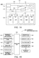
- FIG. 1A is a schematic configuration diagram showing an internal configuration of the banknote handling machine including the banknote shifting device according to the present embodiment
- FIG. 1B is a functional block diagram showing a configuration of a control system in the banknote handling machine shown in FIG. 1A
- FIG. 2 is a configuration diagram showing a schematic configuration when the banknote shifting device in the banknote handling machine shown in FIG. 1A is viewed from above
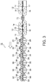
- FIG. 3 is a side view of the banknote shifting device shown in FIG.
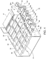
- FIG. 4 is a perspective view of the banknote shifting device shown in FIGS. 2 and 3 .
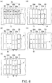
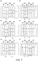
- FIGS. 6 and 7 are explanatory diagrams showing one example of the banknote transporting method by the banknote shifting device shown in FIG. 2 and the like
- FIG. 8 is an explanatory diagram showing another example of the banknote transporting method by the banknote shifting device shown in FIG. 2 and the like.
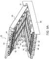
- FIG. 9A is a perspective view showing a state in which an upper cover unit of the banknote shifting device shown in FIG. 2 is opened upward
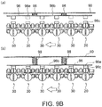
- FIG. 9B is a side view showing a configuration of a position fixing member and an elastic member provided in the banknote shifting device shown in FIG. 2 .
- FIGS. 10 (a) to (e) are explanatory diagrams sequentially showing such an operation that an alignment of a lower guiding unit and an upper guiding unit in each slide type transporting mechanism is performed automatically when closing the upper cover after opening the upper cover unit upward from the lower cover unit to the state as shown in FIG. 9A , in the banknote shifting device shown in FIG. 2 and the like.
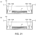
- FIGS. 11 (a) and (b) are diagrams showing such an operation that a position of the upper guiding unit in a width direction of a transport path is automatically fixed to a predetermined position (more specifically, a center position in the width direction of the transport path) when the upper cover unit is opened upward from the lower cover unit to the state as shown in FIG. 9A in the banknote shifting device shown in FIG. 2 and the like.
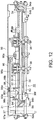
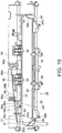
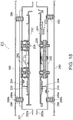
- FIGS. 12 to 17 are longitudinal sectional views showing a configuration of the lower guiding unit, the upper guiding unit, and the like of each slide type transporting mechanism in the banknote shifting device shown in FIG. 2 and the like, respectively.
- a banknote handling machine 100 can perform various processes such as a depositing process and a dispensing process of the banknotes.
- the banknote handling machine 100 is composed of two assemblies including an upper assembly 102 and a lower assembly 104.
- the banknote handling machine 100 includes a substantially rectangular parallelepiped housing 101, an inlet unit 110 for inserting the banknotes into the housing 101 from the outside, and an ejecting unit 112 for ejecting the banknotes from the inside of the housing 101 to the outside.
- a left side surface of the housing 101 in FIG. 1A is a front side of the housing 101, and a right direction in FIG. 1A is a depth direction of the housing 101. Therefore, the inlet unit 110 and the ejecting unit 112 are disposed on the front side of the housing 101.
- a transporting unit 114 for transporting the banknotes one by one is provided.
- the multiple banknotes are placed in a stacked manner in the inlet unit 110 from the outside of the housing 101 by the operator.
- a banknote feeding mechanism 111 is provided in the inlet unit 110.
- the banknote feeding mechanism 111 is configured to feed out the banknotes placed in the inlet unit 110 one by one to the inside of the housing 101 so that the banknotes are sent to the transporting unit 114.
- the banknotes placed on the inlet unit 110 are fed one by one into the housing 101 by the banknote feeding mechanism 111 and are sent to the transporting unit 114, and then are transported one by one in the housing 101 by the transporting unit 114.
- the banknotes are inserted in a stacked state in the inlet unit 110 along the short-edge direction thereof, and the transporting unit 114 transports the banknotes along the short-edge direction thereof.
- a recognition unit 116 is provided in the transporting unit 114, and the recognition unit 116 recognizes a denomination, authenticity, front/back, correctness, new/old, transport status, and the like of the banknote being transported by the transporting unit 114.
- the recognition unit 116 includes an image sensor, and an image of the banknote is taken by this image sensor. Furthermore, in the recognition unit 116, information related to a serial number of the banknote is obtained based on the image of the banknote taken by the image sensor.
- An escrow unit 118 is connected to the transporting unit 114. The banknote recognized by the recognition unit 116 is sent to the escrow unit 118 by the transporting unit 114, and then escrowed in the escrow unit 118.
- a banknote shifting device 10 is provided in the transporting unit 114.
- the banknote shifting device 10 shifts a position of the banknote transported by the transporting unit 114 along a direction perpendicular to a transport direction of the banknote by the transporting unit 114 (that is, along a width direction of the banknote transported by the transporting unit 114).
- the banknote shifting device 10 it is possible to shift the banknote transported by the transporting unit 114, for example, to a center position in the width direction of the transport path of the transporting unit 114. Details of the configuration of the banknote shifting device 10 will be described later.
- the inlet unit 110, the ejecting unit 112, the recognition unit 116, the escrow unit 118 and the banknote shifting device 10 are provided in the upper assembly 102.
- each banknote storage unit 120 is connected to the transporting unit 114, respectively.
- Each banknote storage unit 120 is arranged such that the banknotes sent from the transporting unit 114 are stored in a stacked state and the banknotes stored in the banknote storage unit 120 can be fed out to the transporting unit 114 one by one by a banknote feeding mechanism 122 provided in each banknote storage unit 120.
- the banknotes are stored for each denomination.
- the banknote escrowed in the escrow unit 118 is fed out from the escrow unit 118 to the transporting unit 114, and the fed banknote is sent to each banknote storage unit 120 for each denomination via the banknote shifting device 10 by the transporting unit 114.
- the banknote handling machine 100 of the present embodiment is provided with a controlling unit 150 for controlling each constituent member of the banknote handling machine 100. More specifically, the banknote feeding mechanism 111 provided on the inlet unit 110, the transporting unit 114, the recognition unit 116, the banknote shifting device 10, the escrow unit 118, each banknote feeding mechanism 122 provided on each banknote storage unit 120 are communicably connected to the controlling unit 150, respectively. A signal related to the recognition result of the banknote by the recognition unit 116 is sent to the controlling unit 150 and the controlling unit 150 controls the operation of these constituent members by sending a command signal to each constituent member of the banknote handling machine 100.
- an operation/display unit 152 is communicably connected to the controlling unit 150, respectively.
- the operation/display unit 152 is composed of a touch panel and the like provided on an upper surface of the housing 101, for example.
- Information on a process status such as the depositing process and the dispensing process of the banknotes in the banknote handling machine 100, information on an amount-of-money data of the banknotes stored in each banknote storage unit 120 and the like are displayed on the operation/display unit 152.
- the operator can give various instructions to the controlling unit 150.
- the memory unit 154 stores a process history such as the depositing process and the dispensing process of the banknotes in the banknote handling machine 100, information on the amount-of-money data of the banknotes stored in each banknote storage unit 120 and the like.
- the printing unit 156 is composed of, for example, a printer and the like provided on the upper surface of the housing 101. Information on the process status such as the depositing process and the dispensing process of the banknotes in the banknote handling machine 100, information on the amount-of-money data of the banknotes stored in each banknote storage unit 120 and the like are printed on a receipt and the like by the printing unit 156.
- the controlling unit 150 can transmit and receive signals to and from an external device (specifically, for example, an upper terminal) provided separately from the banknote handling machine 100 according to the present embodiment via the communication interface unit 158.
- the banknote shifting device 10 includes a first fixed transporting unit 20 whose position is fixed and transports the banknotes along a transport path 11, a plurality (for example, four) of slide type transporting mechanisms 30, and a second fixed transporting unit 50 whose position is fixed and transports the banknotes delivered from the slide type transporting mechanisms 30 along the transport path 11.
- Each of the slide type transporting mechanisms 30 is slidable along the width direction of the transport path 11 (up and down direction in FIG. 2 ), and transports the banknotes delivered from the first fixed transporting unit 20, respectively.
- An upstream side transporting unit 12 is provided upstream of the first fixed transporting unit 20 in the transport direction of the banknote.
- the banknote shifting device 10 transports the banknotes one by one from the right side to the left side along the transport path 11 extending in the left-right direction in FIG. 2 . At this time, the banknotes are transported along the short-edge direction thereof.
- the upstream side transporting unit 12 is composed of an upper transporting belt 14 stretched by a plurality of upper rollers 15 and a lower transporting belt 16 stretched by a plurality of lower rollers 17.
- FIG. 2 shows the configuration of the lower transporting belt 16 when the upper transporting belt 14 and the upper rollers 15 are removed from the banknote shifting device 10.
- a drive motor is attached to one lower roller 17 among the plurality of lower rollers 17, and as the lower roller 17 is rotated by this drive motor, the lower transporting belt 16 circulates in the counterclockwise direction in FIG. 3 .
- the upper transporting belt 14 also circulates with the lower transporting belt 16. When the lower transporting belt 16 is circulated in the counterclockwise direction in FIG.
- the upper transporting belt 14 is also circulated in the clockwise direction in FIG. 3 .
- the banknotes are transported from the right side to the left side in FIGS. 2 and 3 in a state of being sandwiched between the upper transporting belt 14 and the lower transporting belt 16.
- the lower transporting belts 16 are arranged to be a pair of left and right along the width direction (up and down direction in FIG. 2 ) of the transport path 11.
- the upper transporting belts 14 provided so as to correspond to the lower transporting belts 16 are also arranged to be a pair of left and right along the width direction of the transport path 11 although not shown.
- the first fixed transporting unit 20 is composed of an upper guiding unit 22 and a lower guiding unit 24 arranged so as to be apart from each other with a small distance therebetween in the vertical direction. Between the upper guiding unit 22 and the lower guiding unit 24, the transport path 11 of the banknote is formed. As shown in FIG. 2 , the lower guiding unit 24 is provided with a pair of left and right drive rollers 26 along the width direction of the transport path 11, and the upper guiding unit 22 is provided with a pair of left and right driven rollers 28 along the width direction of the transport path 11 such that each driven roller 28 faces each drive roller 26.
- FIG. 2 shows the configuration of the lower guiding unit 24 and the drive rollers 26 when the upper guiding unit 22 and the driven rollers 28 are removed from the first fixed transporting unit 20.
- a high friction member such as a rubber is disposed on an outer peripheral surface of each of the drive rollers 26.
- Each of the drive rollers 26 is rotated in the counterclockwise direction in FIG. 3 by a roller driving unit 60 (to be described later) via a drive shaft 29.
- a metal member is disposed on an outer peripheral surface of each of the driven rollers 28.
- Each of the driven rollers 28 is provided on the upper guiding unit 22 so as to come into contact with each drive roller 26 and rotate together with each drive roller 26.
- the banknote is sent to a nip formed between each drive roller 26 and each driven roller 28, the banknote is transported in the left direction in FIGS. 2 and 3 along the transport path 11.
- the second fixed transporting unit 50 is composed of an upper guiding unit 52 and a lower guiding unit 54 arranged so as to be apart from each other with a small distance therebetween in the vertical direction. Between the upper guiding unit 52 and the lower guiding unit 54, the transport path 11 of the banknote is formed. As shown in FIG. 2 , the lower guiding unit 54 is provided with a pair of left and right drive rollers 56 along the width direction of the transport path 11, and the upper guiding unit 52 is provided with a pair of left and right driven rollers 58 along the width direction of the transport path 11 such that each driven roller 58 faces each drive roller 56.
- FIG. 2 shows the configuration of the lower guiding unit 54 and the drive rollers 56 when the upper guiding unit 52 and the driven rollers 58 are removed from the second fixed transporting unit 50.
- a high friction member such as a rubber is disposed on an outer peripheral surface of each of the drive rollers 56.
- Each of the drive rollers 56 is rotated in the counterclockwise direction in FIG. 3 by the roller driving unit 60 (to be described later) via a drive shaft 59.
- a metal member is disposed on an outer peripheral surface of each of the driven rollers 58.
- Each of the driven rollers 58 is provided on the upper guiding unit 52 so as to come into contact with each drive roller 56 and rotate together with each drive roller 56.
- the banknote is sent to a nip formed between each drive roller 56 and each driven roller 58, the banknote is transported in the left direction in FIGS. 2 and 3 along the transport path 11.
- a plurality (for example, four) of slide type transporting mechanisms 30 are arranged in series along the transport direction of the banknotes.
- Each slide type transporting mechanism 30 is slidable along the width direction (up and down direction in FIG. 2 ) of the transport path 11 independently of the other slide type transporting mechanism 30.
- each slide type transporting mechanism 30 can move the banknote along the width direction of the transport path 11. Therefore, the position of the banknote sent from each slide type transporting mechanism 30 to the second fixed transporting unit 50 in the width direction of the transport path 11 is shifted to the predetermined position (for example, the center position).
- each slide type transporting mechanism 30 is composed of an upper guiding unit 32 and a lower guiding unit 34 arranged so as to be spaced apart from each other with a small distance therebetween in the vertical direction. Between the upper guiding unit 32 and the lower guiding unit 34, the transport path 11 of the banknote is formed. As shown in FIG. 2 , the lower guiding unit 34 is provided with a pair of left and right drive rollers 36 along the width direction of the transport path 11, and the upper guiding unit 32 is provided with a pair of left and right driven rollers 38 along the width direction of the transport path 11 such that each driven roller 38 faces each drive roller 36.
- FIG. 2 shows the configuration of the lower guiding unit 34 and the drive rollers 36 when the upper guiding unit 32 and the driven rollers 38 are removed from each slide type transporting unit 30.
- each slide type transporting unit 30 a high friction member such as a rubber is disposed on an outer peripheral surface of each of the drive rollers 36.
- Each of the drive rollers 36 is rotated in the counterclockwise direction in FIG. 3 by the roller driving unit 60 (to be described later) via a drive shaft 39.
- a metal member is disposed on an outer peripheral surface of each of the driven rollers 38.
- Each of the driven rollers 38 is provided on the upper guiding unit 32 so as to come into contact with each drive roller 36 and rotate together with each drive roller 36.
- the banknote is sent to a nip formed between each drive roller 36 and each driven roller 38, the banknote is transported in the left direction in FIGS. 2 and 3 along the transport path 11.
- the upper guiding unit 32 and the lower guiding unit 34 can slide integrally along the width direction of the transport path 11 by the frictional force acting between each driven roller 38 and each drive roller 36.
- the first fixed transporting unit 20, the second fixed transporting unit 50, and each slide type transporting mechanism 30 are provided between a lower cover unit 80 and an upper cover unit 90.
- the upper cover unit 90 is freely rotatable with respect to the lower cover unit 80 about an axis 81. More specifically, the upper guiding unit 22 and the driven rollers 28 of the first fixed transporting unit 20, the upper guiding unit 52 and the driven rollers 58 of the second fixed transporting unit 50, and the upper guiding unit 32 and the driven rollers 38 of each slide type transporting mechanism 30 are provided on the upper cover unit 90.
- the lower guiding unit 24 and the drive rollers 26 of the first fixed transporting unit 20, the lower guiding unit 54 and the drive rollers 56 of the second fixed transporting unit 50, and the lower guiding unit 34 and the drive rollers 36 of each slide type transporting mechanism 30 are provided on the lower cover unit 80. If a trouble such as a jamming of the banknote occurs when the banknote is transported in the first fixed transporting unit 20, each slide type transporting mechanism 30, the second fixed transporting unit 50, and the like, the upper cover unit 90 is opened upward from the lower cover unit 80 as shown in FIG. 9A . This makes it possible to remove the banknote sandwiched between the upper guiding units 22, 32, 52 and the lower guiding units 24, 34, 54 in the first fixed transporting unit 20, each slide type transporting mechanism 30, the second fixed transporting unit 50, and the like.
- the transport path of the banknote is formed between the upper guiding units 22, 32, 52 and the lower guiding units 24, 34, 54 in the first fixed transporting unit 20, each slide type transporting mechanism 30, and the second fixed transporting unit 50.
- a positioning unit 31 see FIGS. 10 to 17 ) such that a relative position of the upper guiding unit 32 with respect to the lower guiding unit 34 in the width direction of the transport path becomes a predetermined position.
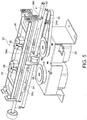
- each slide type transporting mechanism 30 a mechanism for integrally sliding the upper guiding unit 32 and the lower guiding unit 34 along the width direction of the transport path 11 will be described with reference to FIG. 5 .
- two guide rails 40, 41 extending in parallel along the width direction of the transport path 11 are provided below the lower guiding unit 34.
- a first lower member 34a is attached to a center position of the lower guiding unit 34 in a lower portion, and a second lower member 34b and a third lower member 34c are attached to both end positions of the lower guiding unit 34 in the lower portion.
- the first lower member 34a is provided with a tubular member, and the guide rail 40 passes through the tubular member, so that the first lower member 34a is guided along the guide rail 40 in the horizontal direction.
- the second lower member 34b and the third lower member 34c are also provided with tubular members respectively. As the guide rail 41 passes through these tubular members, the second lower member 34b and the third lower member 34c are guided along the guide rail 41 in the horizontal direction.
- an endless drive belt 42 is arranged below the guide rails 40, 41 along the horizontal direction.
- the drive belt 42 is stretched around a plurality of pulleys including a drive pulley 44 (the pulleys other than the drive pulley 44 are not shown in FIG. 5 ).
- a drive motor 46 such as a stepping motor for rotating the drive pulley 44 in both forward and reverse directions is disposed.
- the second lower member 34b attached to the lower part of the lower guiding unit 34 is provided with a belt mounting unit 34d and this belt mounting unit 34d is attached to the drive belt 42.
- the drive belt 42 stretched around the drive pulley 44 circulates.
- the belt mounting unit 34d moves in the horizontal direction
- the second lower member 34b and the third lower member 34c move along the guide rail 41.
- the first lower member 34a also moves along the guide rail 40, and the upper guiding unit 32 and the lower guiding unit 34 integrally slide along the width direction of the transport path 11.
- the drive rollers 26 of the first fixed transporting unit 20, the drive rollers 36 of each slide type transporting mechanism 30, and the drive rollers 56 of the second fixed transporting unit 50 are driven by the roller driving unit 60 which is a single drive system. Details of a configuration of the roller driving unit 60 will be described with reference to FIGS. 2 and 4 .
- the drive shaft 29 of the drive rollers 26 of the first fixed transporting unit 20, the drive shaft 39 of the drive rollers 36 of each slide type transporting mechanism 30, and the drive shaft 59 of the drive rollers 56 of the second fixed transporting unit 50 are provided with gear wheels 29a, 39a and 59a, respectively.
- each drive gear 64 is disposed between the gear wheels 29a, 39a and 59a, respectively.
- a gear wheel 29a provided at the tip portion of the drive shaft 29 of the drive rollers 26 of the first fixed transporting unit 20 is arranged so that the gear wheel 29a and a drive gear 62 mesh with each other.
- the drive gear 62 is arranged so that the drive gear 62 and a drive gear 61 meshes with each other.
- the drive gear 61 is rotated by a drive motor (not shown) such as a stepping motor and the like, so that the gear wheel 29a is rotated via the drive gear 62, and then this rotational driving force is transmitted to each gear wheel 39a and gear wheel 59a via each drive gear 64.
- a drive motor not shown
- each drive roller 26, 36, 56 also rotates integrally.
- each drive gear 64 extends along the width direction of the transport path 11 (that is, the longitudinal direction of each drive shaft 39). Therefore, even when the upper guiding unit 32 and the lower guiding unit 34 of each slide type transporting mechanism 30 slide along the width direction of the transport path 11 and the drive shaft 39 of each drive roller 36 also moves along the width direction of the transport path 11, the coupling between each gear wheel 39a and each drive gear 64 is not disengaged. As a result, even when the drive shaft 39 of each drive roller 36 moves along the width direction of the transport path 11, each drive roller 26, 36, 56 can be integrally rotated by the roller driving unit 60.
- an inlet side banknote detecting sensor 70 is installed upstream of the first fixed transporting unit 20 in the transport direction of the banknote.
- the inlet side banknote detecting sensor 70 detects the length of the banknote in the width direction thereof, the position of the banknote in the width direction of the transport path 11, the skew angle (skew amount) of the banknote, and the like, regarding the banknote transported by the upstream side transporting unit 12 along the transport path 11. Detection information on the banknote detected by the inlet side banknote detecting sensor 70 is sent to the controlling unit 150.
- An inlet side transport timing detecting sensor 74 is installed upstream of the first fixed transporting unit 20 and downstream of the inlet side banknote detecting sensor 70 in the transport direction of the banknote.
- the inlet side transport timing detecting sensor 74 detects the timing of the banknote just before being sent to the first fixed transporting unit 20.
- the detection information on the banknote by the inlet side transport timing detecting sensor 74 is sent to the controlling unit 150.
- the banknote shifting device 10 (specifically, an operation of shifting the banknote along the width direction thereof by the banknote shifting device 10) will be described.
- the operation of the banknote shifting device 10 as described below is performed by the controlling unit 150 controlling each constituent member of the banknote shifting device 10.
- the controlling unit 150 places the upper guiding unit 32 and the lower guiding unit 34 of each slide type transporting mechanism 30 at the center position in the width direction of the transport path 11. Then, when the banknote transported by the transporting unit 114 is sent to the banknote shifting device 10, the controlling unit 150 calculates a movement amount of each slide type transporting mechanism 30 based on a position of the banknote in the width direction of the transport path 11, before being sent to each slide type transporting mechanism 30, detected by the inlet side banknote detecting sensor 70 and the predetermined position of the banknote in the width direction of the transport path 11 (for example, the center position).
- the controlling unit 150 calculates that the movement amount of each slide type transporting mechanism 30 is 10 mm.
- the movement amount of each slide type transporting mechanism 30 is the same as the movement amount of the transporting member composed of the drive rollers 36 and the driven rollers 38.
- the controlling unit 150 controls each slide type transporting mechanism 30 so as to slide each slide type transporting mechanism 30 along the width direction of the transport path 11 by the calculated movement amount.
- the controlling unit 150 slides each slide type transporting mechanism 30 along the width direction of the transport path 11 such that the sum of the movement amounts of the banknote in the width direction of the transport path 11 by each slide type transporting mechanism 30 becomes the calculated movement amount.
- FIGS. 6 (a) to (e) and FIGS. 7 (a) to (f) are explanatory diagrams showing an example of the banknote transporting method by the banknote shifting device 10. The operation as shown in FIGS.
- FIGS. 6 and 7 As the four slide type transporting mechanisms 30, a first slide type transporting mechanism 30a, a second slide type transporting mechanism 30b, a third slide type transporting mechanism 30c, and a fourth slide type transporting mechanism 30d are provided.
- the banknote sequentially transported by the first to fourth slide type transporting mechanisms 30a to 30d are denoted by reference symbol P.
- Such movement of the first slide type transporting mechanism 30a and the second slide type transporting mechanism 30b is performed until the banknote is sent to the nip between each drive roller 36 and each driven roller 38 of the first slide type transporting mechanism 30a. Then, as shown in FIG. 6 (c) , after the first slide type transporting mechanism 30a and the second slide type transporting mechanism 30b are stopped, the banknote is sent to the nip between each drive roller 36 and each driven roller 38 of the first slide type transporting mechanism 30a.
- the third slide type transporting mechanism 30c and the fourth slide type transporting mechanism 30d start to move, as shown in FIG. 7 (a) , in the direction approaching the banknote (that is, downward in FIG. 7 (a) ), in order to shift this banknote to the predetermined position (for example, the center position) in the width direction of the transport path 11.
- Such movement of the third slide type transporting mechanism 30c and the fourth slide type transporting mechanism 30d is performed until the banknote is sent to the nip portion between each drive roller 36 and each driven roller 38 of the third slide type transporting mechanism 30c.
- FIG. 7 (b) after the third slide type transporting mechanism 30c and the fourth slide type transporting mechanism 30d are stopped, the banknote is sent to the nip between each drive roller 36 and each driven roller 38 of the third slide type transporting mechanism 30c.
- the controlling unit 150 moves the former slide type transporting mechanism (specifically, the first slide type transporting mechanism 30a and the second slide type transporting mechanism 30b) to a position where the following banknote is received.
- the banknote shifting device 10 can cope with the banknotes continuously sent.
- each of the first to fourth slide type transporting mechanisms 30a to 30d slides along the width direction of the transport path 11 independently of the other slide type transporting mechanisms 30a to 30d, after the banknote is transferred from the first slide type transporting mechanism 30a to the second slide type transporting mechanism 30b, for example, by moving the first slide type transporting mechanism 30a to the position to receive the following banknote, it is possible to cope with the banknotes continuously sent.
- the controlling unit 150 slides each slide type transporting mechanism 30a to 30d along the width direction of the transport path 11 such that the sum of the movement amounts of the banknote by the first to fourth slide type transporting mechanisms 30a to 30d is the same as the movement amount calculated when the banknote is detected by the inlet side banknote detecting sensor 70 (that is, the distance between the position of the banknote in the width direction of the transport path 11 before being sent to each slide type transporting mechanism 30 and the predetermined position (for example, the center position) of the banknote in the width direction of the transport path 11 set in advance).
- the movement amount calculated by the controlling unit 150 when the banknote is detected by the inlet side banknote detecting sensor 70 is, for example, 18 mm and the maximum movement amount of each of the slide type transporting mechanisms 30a to 30d is, for example, 10 mm
- the slide amount of the banknote when the banknote is slid along the width direction of the transport path 11 by the first slide type transporting mechanism 30a and the second slide type transporting mechanism 30b is, for example, 10 mm
- the slide amount of the banknote when the banknote is slid along the width direction of the transport path 11 by the third slide type transporting mechanism 30c and the fourth slide type transporting mechanism 30d is, for example, 8 mm.
- the controlling unit 150 slides only some slide type transporting mechanism or mechanisms along the width direction of the transport path 11 among multiple (specifically, four) slide type transporting mechanisms 30a to 30d.
- the movement amount calculated by the controlling unit 150 when the banknote is detected by the inlet side banknote detecting sensor 70 is, for example, 8 mm and the maximum movement amount of each of the slide type transporting mechanisms 30a to 30d is, for example, 10 mm
- the banknote is slid by 8 mm along the width direction of the transport path 11 by the first slide type transporting mechanism 30a and the second slide type transporting mechanism 30b, and the third slide type transporting mechanism 30c and the fourth slide type transporting mechanism 30d do not slide along the width direction of the transport path 11. This makes it possible to reduce the number of the slide type transporting mechanisms 30 that slide along the width direction of the transport path 11.
- the timing of starting to move each slide type transporting mechanism 30a to 30d will be described below.
- the period of the time from the detection of the banknote by the inlet side banknote detecting sensor 70 or the inlet side transport timing detecting sensor 74 to the start of sliding of each slide type transporting mechanism 30a to 30d is set for each slide type transporting mechanism 30a to 30d, respectively, in the controlling unit 150.
- the controlling unit 150 starts to slide each slide type transporting mechanism 30a to 30d along the width direction of the transport path 11.
- the first slide type transporting mechanism 30a and the second slide type transporting mechanism 30b integrally slide along the width direction of the transport path 11 and the third slide type transporting mechanism 30c and the fourth slide type transporting mechanism 30d integrally slide along the width direction of the transport path 11; however, it is not limited to such an aspect.
- Each of the first to fourth slide type transporting mechanisms 30a to 30d may slide along the width direction of the transport path 11 independently of the other slide type transporting mechanisms 30a to 30d.
- the controlling unit 150 After transporting the banknote by each of the slide type transporting mechanisms 30a to 30d, the controlling unit 150 returns the slide type transporting mechanisms 30a to 30d to the predetermined position (for example, the center position) in the width direction of the transport path 11; however, it is not limited to such an aspect. After transporting the banknote by each of the slide type transporting mechanisms 30a to 30d, the controlling unit 150 may slide each of the slide type transporting mechanisms 30a to 30d to a position to receive the following banknote.
- the predetermined position for example, the center position
- the banknote transporting method by the banknote shifting device 10 shown in FIG. 2 and the like is not limited to the example shown in FIGS. 6 and 7 .
- Another example of the banknote transporting method by the banknote shifting device 10 shown in FIG. 2 and the like will be described with reference to FIGS. 8 (a) to (f) .
- FIG. 8 similar to FIGS. 6 and 7 , as the four slide type transporting mechanisms 30, the first slide type transporting mechanism 30a, the second slide type transporting mechanism 30b, the third slide type transporting mechanism 30c, and the fourth slide type transporting mechanism 30d are provided.
- the banknote sequentially transported by the first to fourth slide type transporting mechanisms 30a to 30d are denoted by reference symbol P.
- FIG. 8 (a) when the banknote is transferred from the upstream side transporting unit 12 to the first fixed transporting unit 20, if the position of this banknote in the width direction of the transport path 11 deviates from the predetermined position (for example, the center position), the first slide type transporting mechanism 30a and the second slide type transporting mechanism 30b start to move, as shown in FIG. 8 (b) , in the direction approaching the banknote (that is, downward in FIG. 8 (b) ), in order to shift this banknote to the predetermined position in the width direction of the transport path 11.
- the predetermined position for example, the center position
- the first slide type transporting mechanism 30a and the second slide type transporting mechanism 30b are moved from the center position downward in FIG. 8 (b) by, for example, 5 mm.
- Such movement of the first slide type transporting mechanism 30a and the second slide type transporting mechanism 30b is performed until the banknote is sent to the nip between each drive roller 36 and each driven roller 38 of the first slide type transporting mechanism 30a.
- FIG. 8 compared to the example shown in FIGS.
- the movement amount of the first slide type transporting mechanism 30a and the second slide type transporting mechanism 30b from the predetermined position is halved.
- the first slide type transporting mechanism 30a and the second slide type transporting mechanism 30b are moved upward to shift the banknote close to the predetermined position (for example, center position) in the width direction of the transport path 11.
- the first slide type transporting mechanism 30a and the second slide type transporting mechanism 30b are moved to a position in the upward direction in FIG.
- the first slide type transporting mechanism 30a and the second slide type transporting mechanism 30b are moved from the center position to, for example, 5 mm in the upward direction in FIG. 8 (c) .
- the amount of the deviation of the banknote from the center position in the width direction of the transport path 11 is reduced to 10 mm.
- the third slide type transporting mechanism 30c and the fourth slide type transporting mechanism 30d start to move, as shown in FIG. 8 (c) , in the direction approaching the banknote (that is, downward in FIG. 8 (c) ). Specifically, the third slide type transporting mechanism 30c and the fourth slide type transporting mechanism 30d are moved from the center position downward in FIG. 8 (c) by, for example, 5 mm. Such movement of the third slide type transporting mechanism 30c and the fourth slide type transporting mechanism 30d is performed until the banknote is sent to the nip between each drive roller 36 and each driven roller 38 of the third slide type transporting mechanism 30c. In the example shown in FIG. 8 , compared to the example shown in FIGS.
- the movement amount of the third slide type transporting mechanism 30c and the fourth slide type transporting mechanism 30d from the predetermined position is halved.
- the predetermined position for example, the center position
- FIG. 8 (d) when the rear end portion of the banknote in the transport direction comes out of the nip between each drive roller 36 and each driven roller 38 of the second slide type transporting mechanism 30b, the first slide type transporting mechanism 30a and the second slide type transporting mechanism 30b return to the predetermined position (specifically, the center position).
- the predetermined position for example, the center position
- the third slide type transporting mechanism 30c and the fourth slide type transporting mechanism 30d are moved upward to further shift the banknote close to the predetermined position (for example, center position) in the width direction of the transport path 11.
- the third slide type transporting mechanism 30c and the fourth slide type transporting mechanism 30d are moved to a position in the upward direction in FIG. 8 (e) rather than the predetermined position.
- the third slide type transporting mechanism 30c and the fourth slide type transporting mechanism 30d are moved from the center position to, for example, 5 mm in the upward direction in FIG. 8 (e) .
- the banknote is transferred from the fourth slide type transporting mechanism 30d to the second fixed transporting unit 50, and the banknote is sent further downstream from the second fixed transporting unit 50.
- the third slide type transporting mechanism 30c and the fourth slide type transporting mechanism 30d return to the predetermined position (specifically, the center position).
- each of the slide type transporting mechanisms 30a to 30d is moved to both sides (specifically, the upper side and the lower side in FIG.
- the banknote shifting device 10 of the present embodiment by opening the upper cover unit 90 upward from the lower cover unit 80, the banknote causing the trouble such as the jamming is removed, and then the upper cover unit 90 is closed, whereby, the transport path of the banknote is formed between the upper guiding units 22, 32, 52 and the lower guiding units 24, 34, 54 in the first fixed transporting unit 20, each slide type transporting mechanism 30, and the second fixed transporting unit 50.
- the positioning unit 31 is provided in each slide type transporting mechanism 30 to position the lower guiding unit 34 and the upper guiding unit 32 when the upper cover unit 90 is closed such that the relative position of the upper guiding unit 32 with respect to the lower guiding unit 34 in the width direction of the transport path becomes the predetermined position. Details of the configuration of the positioning unit 31 will be described later.
- the positioning unit 31 is provided corresponding to each slide type transporting mechanism 30.
- a first supporting unit 82 for supporting the lower guiding unit 34 is provided in the lower cover unit 80 (not shown in FIGS. 12 to 17 ).
- the upper cover unit 90 is provided with a second supporting unit 92 for supporting the upper guiding unit 32.
- FIG. 9A when the upper cover unit 90 is opened upward from the lower cover unit 80, the second supporting unit 92 also moves integrally with the upper cover unit 90, and the second supporting unit 92 moves away from the first supporting unit 82. That is, the second supporting unit 92 is movable between a first position (see FIGS.
- positioning of the lower guiding unit 34 and the upper guiding unit 32 is performed by the positioning unit 31 such that the relative position of the upper guiding unit 32 with respect to the lower guiding unit 34 in the width direction of the transport path (that is, the left-right direction in FIGS. 12 to 17 ) is the predetermined position.
- first guiding members 84 are provided at both ends of the lower guiding unit 34 in each slide type transporting mechanism 30 and each first guiding member 84 includes a first inclined surface 84a inclined with respect to the width direction of the transport path (that is, the left-right direction in FIGS. 12 to 17 ).
- the first inclined surfaces 84a of the pair of left and right first guiding members 84 face the upper guiding unit 32 side supported by the second supporting unit 92.
- Second guiding members 94 are provided at both ends of the upper guiding unit 32 in each slide type transporting mechanism 30 so as to face the respective first guiding members 84.
- the pair of left and right second guiding members 94 are shaped so as to protrude downward from the upper guiding unit 32.
- the lower guiding unit 34 and the upper guiding unit 32 move towards each other, the lower end portion of either one of the pair of left and right second guiding members 94 contacts the first inclined surface 84a of the first guiding member 84. Then, as the lower end portion of the second guiding member 94 moves along the first inclined surface 84a of the first guiding member 84, the second guiding member 94 and the first guiding member 84 guide each other. Therefore, the lower guiding unit 34 moves relative to the upper guiding unit 32 along the width direction of the transport path.
- each of the pair of left and right first guiding members 84 has a recess 84b for accommodating the lower end portion of each second guiding member 94 when the second supporting unit 92 supporting the upper guiding unit 32 moves to the first position as shown in FIGS. 12 and 17 .
- the lower guiding unit 34 can not move in the width direction of the transport path with respect to the upper guiding unit 32. As a result, the positioning of the lower guiding unit 34 and the upper guiding unit 32 in the width direction of the transport path is performed.
- a position fixing member 96 is provided in the second supporting unit 92.
- the position fixing member 96 fixes the position of the upper guiding unit 32 in the width direction of the transport path to the predetermined position (more specifically, the center position in the width direction of the transport path), when the second supporting unit 92 moves from the first position as shown in FIGS. 12 and 17 to the second position as shown in FIGS. 15 and 16 .
- the position fixing member 96 includes a lever 96b that is rotatable around an axis 96a provided on the second supporting unit 92. As shown in FIGS.
- FIG. 9B (a) is a view showing the state when the second supporting unit 92 is located at the first position as shown in FIGS. 12 and 17
- FIG. 9B (b) is a view showing the state when the second supporting unit 92 is located at the second position as shown in FIGS. 15 and 16 .
- a third guiding member 96c is provided on the surface of the upper guiding unit 32 on the side opposite to the lower guiding unit 34 (that is, the upper surface of the upper guiding unit 32 in FIGS. 12 to 17 ).
- the third guiding member 96c includes a second inclined surface 96d inclined with respect to the width direction of the transport path.
- a fourth guiding member 96e facing the third guiding member 96c provided on the upper guiding unit 32.
- the fourth guiding member 96e has a shape protruding downward from the lever 96b.
- a lower end portion of the fourth guiding member 96e contacts the second inclined surface 96d of the third guiding member 96c, and then the lower end portion of the fourth guiding member 96e relatively moves along the second inclined surface 96d of the third guiding member 96c.
- the upper guiding unit 32 moves relative to the second supporting unit 92 along the width direction of the transport path.
- a plurality of (specifically, six) fourth guiding members 96e are provided in one lever 96b so as to correspond to the plurality of third guiding members 96c provided in each of the first fixed transporting unit 20, each slide type transporting mechanism 30 and the second fixed transporting unit 50.
- the third guiding member 96c includes a recess 96f for accommodating the lower end portion of the fourth guiding member 96e when the second supporting unit 92 supporting the upper guiding unit 32 moves to the second position as shown in FIGS. 15 and 16 .
- the upper guiding unit 32 can not move in the width direction of the transport path with respect to the second supporting unit 92. As a result, positioning of the second supporting unit 92 and the upper guiding unit 32 in the width direction of the transport path is performed.
- the upper guiding unit 32 is positioned at the center position of the second supporting unit 92 in the width direction of the transport path. As a result, the upper guiding unit 32 is fixed to the center position in the width direction of the transport path.
- an elastic member 98 is provided between the lever 96b of the position fixing member 96 provided on the second supporting unit 92 and the upper cover unit 90.
- the elastic member 98 urges the lever 96b away from the upper cover unit 90 toward the upper guiding unit 32.
- the elastic member 98 includes a spring 98a disposed between the lever 96b of the position fixing member 96 and the upper cover unit 90.
- the spring 98a is wound around a rod member 98b provided so as to extend downward from the lower surface of the upper cover unit 90.
- the elastic member 98 including the spring 98a urges the lever 96b away from the upper cover unit 90 toward the upper guiding unit 32.
- the second supporting unit 92 moves from the first position as shown in FIGS. 12 and 17 to the second position as shown in FIGS. 15 and 16 , as the elastic member 98 including the spring 98a urges the lever 96b toward the upper guiding unit 32 (that is, as the force to rotate the lever 96b in the counterclockwise direction in FIG. 12 and the like about the axis 96a is given to the lever 96b by the elastic member 98), the fourth guiding member 96e contacts the third guiding member 96c and relatively moves along the second inclined surface 96d.
- the upper guiding unit 32 moves along the width direction of the transport path, and the upper guiding unit 32 is guided to the predetermined position in the width direction of the transport path (more specifically, the center position in the width direction of the transport path).
- the lever 96b, the third guiding member 96c, the fourth guiding member 96e, the elastic member 98 and the like constitute the position fixing member 96 for fixing the position of the upper guiding unit 32 in the width direction of the transport path to the predetermined position (more specifically, the center position in the width direction of the transport path) when the second supporting unit 92 moves to the second position as shown in FIGS. 15 and 16 .
- the second supporting unit 92 is provided with a release member 97 for releasing the position fixed state of the upper guiding unit 32 by the position fixing member 96 when the second supporting unit 92 moves from the second position as shown in FIGS. 15 and 16 to the first position as shown in FIGS. 12 and 17 .
- a rod member 82a extending upward from the first supporting unit 82 is provided.
- a contacting member 97a facing the rod member 82a provided on the first supporting unit 82.
- the contacting member 97a contacts the upper end portion of the rod member 82a provided in the first supporting unit 82.
- the contacting member 97a provided on the lever 96b is pushed upward in FIGS. 12 to 17 by the upper end portion of the rod member 82a provided on the first supporting unit 82, and the lever 96b rotates in the clockwise direction about the axis 96a, when the second supporting unit 92 moves from the second position as shown in FIGS. 15 and 16 to the first position as shown in FIGS. 12 and 17 .
- the fourth guiding member 96e provided on the lever 96b moves in a direction away from the third guiding member 96c, and the distance between the fourth guiding member 96e and the third guiding member 96c increases.
- the fourth guiding member 96e comes out upward from the recess 96f of the third guiding member 96c, so that the position fixed state of the upper guiding unit 32 by the position fixing member 96 is released.
- the second supporting unit 92 moves to the second position as shown in FIGS. 15 and 16
- the contacting member 97a separates upward from the upper end portion of the rod member 82a provided on the first supporting unit 82.
- the elastic member 98 including the spring 98a is provided between the lever 96b and the upper cover unit 90 and the force to rotate the lever 96b in the counterclockwise direction about the axis 96a is always given to the lever 96b by the elastic member 98.
- the contacting member 97a provided on the lever 96b comes into contact with the upper end portion of the rod member 82a provided on the first supporting unit 82 and is pushed upward.
- the spring 98a of the elastic member 98 deforms so as to contract vertically. In this way, by increasing the distance between the upper guiding unit 32 and the lever 96b of the position fixing member 96, the position fixed state of the upper guiding unit 32 by the position fixing member 96 is released.
- FIG. 10 an explanation will be given of an operation in which the alignment of the lower guiding unit 34 and the upper guiding unit 32 in each slide type transporting mechanism 30 is performed automatically when the upper cover unit 90 is closed after opening the upper cover unit 90 upward from the lower cover unit 80 to the state as shown in FIG. 9A .
- FIG. 11 an operation in which the position of the upper guiding unit 32 in the width direction of the transport path is automatically fixed to the predetermined position (more specifically, the center position in the width direction of the transport path), when the upper cover unit 90 is opened upward from the lower cover unit 80 to the state as shown in FIG. 9A , will be described.
- FIGS. 12 and 17 show a state in which the upper cover unit 90 is closed and the second supporting unit 92 provided on the upper cover unit 90 is located at the first position as shown in FIGS. 12 and 17 .
- the position of each driven roller 38 provided on the upper guiding unit 32 and the position of each drive roller 36 provided on the lower guiding unit 34 in the width direction of the transport path substantially coincide with each other and then the outer circumferential surface of each driven roller 38 and the outer circumferential surface of each drive roller 36 are in contact with each other.
- the upper cover unit 90 is opened upward from the lower cover unit 80 as shown in FIG. 9A .
- the upper guiding unit 32 separates upward from the lower guiding unit 34, as shown in FIG. 10 (b) and FIG. 11 (b) , and then it becomes possible to remove the banknote sandwiched between the upper guiding unit 32 and the lower guiding unit 34.
- the second supporting unit 92 provided on the upper cover unit 90 moves upward away from the first supporting unit 82 provided on the lower cover unit 80.
- the lower end portion of the fourth guiding member 96e enters the recess 96f of the third guiding member 96c.
- the position of the upper guiding unit 32 in the width direction of the transport path is automatically fixed to the predetermined position (more specifically, the center position in the width direction of the transport path). As shown in FIG.
- the lever 96b is disposed so as to extend over the first fixed transporting unit 20, each slide type transporting mechanism 30, and the second fixed transporting unit 50 above these first fixed transporting unit 20, each slide type transporting mechanism 30 and second fixed transporting unit 50, and a plurality of fourth guiding members 96e are provided in one lever 96b so as to correspond to the plurality of third guiding members 96c provided on each of the first fixed transporting unit 20, each slide type transporting mechanism 30 and the second fixed transporting unit 50.
- the fourth guiding member 96e of each slide type transporting mechanism 30 simultaneously contacts the third guiding member 96c and relatively moves along the second inclined surface 96d, when the second supporting unit 92 moves to the second position and the lever 96b is pushed in the direction approaching the upper guiding unit 32 by the elastic member 98 such as the spring 98a, as shown in FIG. 9B (b) . Therefore, the position of the upper guiding unit 32 of each slide type transporting mechanism 30 is simultaneously fixed to the predetermined position (specifically, the center position in the width direction of the transport path).
- the second supporting unit 92 supporting the upper guiding unit 32 (second slide unit) is movable relative to the first supporting unit 82 to move between the first position (see FIGS. 12 and 17 ) in which the lower guiding unit 34 (first slide unit) and the upper guiding unit 32 face each other to form the transport path of the banknote between the lower guiding unit 34 and the upper guiding unit 32 and the second position in which the upper guiding unit 32 is separated from the lower guiding unit 34 to open the transport path of the banknote.
- the lower guiding unit 34 and the upper guiding unit 32 are positioned by the positioning unit 31 such that the relative position of the upper guiding unit 32 with respect to lower guiding unit 34 in the width direction of the transport path becomes the predetermined position when the second supporting unit 92 moves to the first position.
- This makes it possible to align the positions of the lower guiding unit 34 and the upper guiding unit 32 in the width direction of the transport path when closing the second supporting unit 92 and forming the transport path of the banknote between the lower guiding unit 34 and the upper guiding unit 32. Therefore, it is possible to properly transport the banknote between the lower guiding unit 34 and the upper guiding unit 32.
- the positioning unit 31 is not provided, when the lower guiding unit 34 slides along the width direction of the transport path in a certain slide type transporting mechanism 30 when the upper cover unit 90 is opened upward, as the upper cover unit 90 is closed with the positions of the lower guiding unit 34 and the upper guiding unit 32 being displaced, the position of each drive roller 36 provided on the lower guiding unit 34 and each driven roller 38 provided on the upper guiding unit 32 do not match. At this time, there was a problem that the banknote can not be transported.
- the positioning unit 31 aligns the lower guiding unit 34 and the upper guiding unit 32 in the width direction of the transport path. This makes it possible to align each drive roller 36 provided on the lower guiding unit 34 and each driven roller 38 provided on the upper guiding unit 32 so that it is possible to transport the banknote appropriately between each drive roller 36 and each driven roller 38.
- the positioning unit 31 for positioning the lower guiding unit 34 and the upper guiding unit 32 such that the relative position of the upper guiding unit 32 with respect to lower guiding unit 34 in the width direction of the transport path becomes the predetermined position when the second supporting unit 92 moves to the first position inlcudes the guiding member provided on at least one of the lower guiding unit 34 and the upper guiding unit 32 and the guiding member aligns the lower guiding unit 34 and the upper guiding unit 32 in the width direction of the transport path when the second supporting unit 92 moves to the first position as shown in FIGS. 12 and 17 .
- the guiding member includes the first guiding member 84 provided on the lower guiding unit 34 and the second guiding member 94 provided on the upper guiding unit 32 so as to face the first guiding member 84.
- the first guiding member 84 includes the first inclined surface 84a inclined with respect to the width direction of the transport path.
- the first inclined surface may be formed in the second guiding member 94 provided on the upper guiding unit 32 rather than the first guiding member 84 provided on the lower guiding unit 34 and the first guiding member 84 may protrude upward from the lower guiding unit 34.
- the second supporting unit 92 moves to the first position
- the upper end portion of first guiding member 84 is guided along the first inclined surface of the second guiding member 94 and then the second guiding member 94 and the first guiding member 84 guide each other so that the lower guiding unit 34 and the upper guiding unit 32 are aligned.
- the above described guiding member may be provided only in one of the lower guiding unit 34 and the upper guiding unit 32.
- the positioning unit 31 includes the position fixing member 96 that fixes the position of the upper guiding unit 32 in the width direction of the transport path when the second supporting unit 92 moves to the second position as shown in FIGS. 15 and 16 .
- the positioning unit 31 further includes the release member 97 that releases the position fixed state of the upper guiding unit 32 by the position fixing member 96 when the second supporting unit 92 moves to the first position as shown in FIGS. 12 and 17 .
- the position fixing member 96 may be configured to fix the position of the lower guiding unit 34 instead of the upper guiding unit 32 in the width direction of the transport path, when the second supporting unit 92 moves to the second position as shown in FIGS. 15 and 16 .
- the position fixing member 96 may be configured to fix the positions of both the lower guiding unit 34 and the upper guiding unit 32 in the width direction of the transport path. Details of such a modified example will be described later.
- the release member 97 includes the contacting member 97a provided on the position fixing member 96 and contacting the first supporting unit 82 (specifically, the upper end portion of the rod member 82a provided on the first supporting unit 82) when the second supporting unit 92 moves to the first position.
- the position fixed state of the upper guiding unit 32 by the position fixing member 96 is released as the contacting member 97a provided on the position fixing member 96 is brought into contact with the first supporting unit 82 and pushed, and then the distance between the upper guiding unit 32 and the position fixing member 96 increases, when the second supporting unit 92 moves to the first position.
- the position fixed state of the upper guiding unit 32 by the position fixing member 96 is released as the contacting member 97a provided on the position fixing member 96 is brought into contact with the first supporting unit 82 and is pushed so that the elastic member 98 provided between the lever 96b of the position fixing member 96 and the upper cover unit 90 is deformed in the vertical direction, and then the distance between the upper guiding unit 32 and the lever 96b of the position fixing member 96 increases, when the second supporting unit 92 moves to the first position.
- the position fixing member 96 guides and fixes the upper guiding unit 32 to the predetermined position in the width direction of the transport path (more specifically, the center position in the width direction of the transport path) when the second supporting unit 92 moves to the second position.
- the position fixing member 96 includes the third guiding member 96c provided on the upper guiding unit 32 and including the second inclined surface 96d inclined with respect to the width direction of the transport path and the fourth guiding member 96e that contacts the third guiding member 96c when the second supporting unit 92 moves to the second position.
- the fourth guiding member 96e comes in contact with the third guiding member 96c provided on the upper guiding unit 32 and relatively moves along the second inclined surface 96d so that the upper guiding unit 32 moves along the width direction of the transport path and is fixed to the predetermined position in the width direction of the transport path, when the second supporting unit 92 moves to the second position.
- the position fixing member 96 includes the lever 96b rotatable about the axis 96a provided on the second supporting unit 92 and provided with the fourth guiding member 96e, and the elastic member 98 provided between the lever 96b and the upper cover unit 90 and biasing the lever 96b in the direction toward the upper guiding unit 32 while leaving the lever 96b away from the upper cover unit 90.
- the fourth guiding member 96e contacts the third guiding member 96c by the elastic member 98 biasing the lever 96b toward the upper guiding unit 32, and the fourth guiding member 96e relatively moves along the second inclined surface 96d so that the upper guiding unit 32 moves along the width direction of the transport path and is fixed to the predetermined position in the width direction of the transport path, when the second supporting unit 92 moves to the second position.
- a plurality of combinations that is, a plurality of slide type transporting mechanisms 30
- a plurality of positioning units 31 are provided so as to correspond to each of a plurality of combinations (that is, a plurality of slide type transporting mechanisms 30).
- the position fixing member 96 of the positioning unit 31 is provided to extend over a plurality of combinations. The position fixing member 96 simultaneously fixes the position of the upper guiding unit 32 in each of the plurality of combinations in the width direction of the transport path when the second supporting unit 92 moves to the second position.
- the lever 96b of the position fixing member 96 is disposed so as to extend over the first fixed transporting unit 20, each slide type transporting mechanism 30, and the second fixed transporting unit 50 above these first fixed transporting unit 20, each slide type transporting mechanism 30 and second fixed transporting unit 50.
- a plurality of fourth guiding members 96e are provided on one lever 96b so as to correspond to the plurality of third guiding members 96c provided on each of the first fixed transporting unit 20, each slide type transporting mechanism 30 and the second fixed transporting unit 50.
- the fourth guiding member 96e of each slide type transporting mechanism 30 simultaneously contacts the third guiding member 96c and relatively moves along the second inclined surface 96d, when the second supporting unit 92 moves to the second position and the lever 96b is pushed in the direction approaching the upper guiding unit 32 by the elastic member 98 such as the spring 98a, as shown in FIG. 9B (b) . Therefore, the position of the upper guiding unit 32 of each slide type transporting mechanism 30 is simultaneously fixed to the predetermined position (specifically, the center position in the width direction of the transport path).
- banknote shifting device 10 according to the present embodiment and the banknote handling machine 100 including the banknote shifting device 10 are not limited to the above-described aspects, and various modifications can be made.
- the position fixing member 96 for fixing the position of the upper guiding unit 32 in the width direction of the transport path when the second supporting unit 92 moves to the second position can be omitted. Also, it is possible to omit the release member 97 for releasing the position fixed state of the upper guiding unit 32 by the position fixing member 96.
- the banknote shifting device when the second supporting unit 92 moves to the second position, the upper guiding unit 32 and the lower guiding unit 34 are movable in the width direction of the transport path.
- the second supporting unit 92 moves from the second position to the first position, the positioning of the lower guiding unit 34 and the upper guiding unit 32 in the width direction of the transport path is performed by the first guiding member 84 and the second guiding member 94. Therefore, the relative position of the upper guiding unit 32 with respect to the lower guiding unit 34 in the width direction of the transport path becomes the predetermined position. That is, when the second supporting unit 92 moves to the first position, the position of each drive roller 36 provided on the lower guiding unit 34 and the position of each driven roller 38 provided on the upper guiding unit 32 in the width direction of the transport path are substantially aligned.
- the position fixing member 96 and the release member 97 are omitted, when the second supporting unit 92 moves to the second position, there is a possibility that the lower guiding unit 34 moves to the leftmost side in the width direction of the transport path and the upper guiding unit 32 moves to the rightmost side in the width direction of the transport path, for example.
- the length of the first guiding member 84 in the width direction of the transport path is made larger than the aspect shown in FIGS. 12 to 17 (specifically, it is doubled in size).
- the position fixing member 96 and the release member 97 are installed, when the second supporting unit 92 moves to the second position, the upper guiding unit 32 is fixed to the center position in the width direction of the transport path, for example. Therefore, as compared with the case where the upper guiding unit 32 and the lower guiding unit 34 are respectively movable in the width direction of the transport path, the maximum distance between the lower guiding unit 34 and the upper guiding unit 32 in the width direction of the transport path is halved. Therefore, the length of the first guiding member 84 in the width direction of the transport path (specifically, the length of the first inclined surface 84a in the width direction of the transport path) can also be halved.
- a position fixing member that fixes the position of the lower guiding unit 34 in the width direction of the transport path to the predetermined position (for example, the center position in the width direction of the transport path) when the second supporting unit 92 moves to the second position, and a release member that releases the position fixed state of the lower guiding unit 34 by the position fixing member may be provided, instead of providing the first guiding member 84 and the second guiding member 94.
- the position fixing member that fixes the position of the lower guiding unit 34 in the width direction of the transport path to the predetermined position when the second supporting unit 92 moves to the second position has substantially the same configuration as the position fixing member 96 that fixes the position of the upper guiding unit 32 to the predetermined position as described above.
- the release member that releases the position fixed state of the lower guiding unit 34 by the position fixing member has substantially the same configuration as the release member 97 that releases the position fixed state of the upper guiding unit 32 by the position fixing member 96 as described above.
- the positions of the lower guiding unit 34 and the upper guiding unit 32 in the width direction of the transport path are respectively fixed to the predetermined positions (for example, the center positions in the width direction of the transport path) when the upper cover unit 90 is opened upward from the lower cover unit 80. Therefore, it is prevented that the relative positions of the lower guiding unit 34 and the upper guiding unit 32 in the width direction of the transport path deviate. As a result, even when the upper cover unit 90 is closed, the relative position of the upper guiding unit 32 with respect to the lower guiding unit 34 in the width direction of the transport path becomes the predetermined position. That is, when the second supporting unit 92 moves to the first position, the position of each drive roller 36 provided on the lower guiding unit 34 and the position of each driven roller 38 provided on the upper guiding unit 32 in the width direction of the transport path are substantially aligned.
- the lower guiding unit 34 is slid along the width direction of the transport path by the drive motor 46 such as the stepping motor and the like.
- the drive motor 46 such as the stepping motor and the like.
- the torque of the drive motor 46 is large, when the upper cover unit 90 is opened upward from the lower cover unit 80 and the second supporting unit 92 is moved to the second position as shown in FIGS. 15 and 16 , the lower guiding unit 34 is less likely to move in the width direction of the transport path by the torque of the drive motor 46 when trying to move the lower guiding unit 34 in the width direction of the transport path.
- the drive motor 46 such as the stepping motor that slides the lower guiding unit 34 along the width direction of the transport path functions as the position fixing member for fixing the position of the lower guiding unit 34 in the width direction of the transport path when the second supporting unit 92 moves to the second position.
- the installation of the position fixing member 96 for fixing the position of the upper guiding unit 32 in the width direction of the transport path when the second supporting unit 92 moves to the second position and the release member 97 for releasing the position fixed state of the upper guiding unit 32 by the position fixing member 96 can be omitted. If the installation of the position fixing member 96 and the release member 97 is omitted, when the second supporting unit 92 moves to the first position, as the load is applied to the lower guiding unit 34 by the drive motor 46, the lower guiding unit 34 does not move in the width direction of the transport path and the upper guiding unit 32 moves along the width direction of the transport path, when the second guiding member 94 relatively moves along the first inclined surface 84a of the first guiding member 84. As a result, the upper guiding unit 32 is aligned with respect to the lower guiding unit 34.
- a slide type transporting mechanism 210 as shown in FIG. 18 includes an upper guiding unit 232 and a lower guiding unit 234 arranged so as to be spaced apart from each other by a small distance. Between these upper guiding unit 232 and lower guiding unit 234, a transport path of the banknote is formed. As shown in FIG. 18 , the lower guiding unit 234 is provided with a pair of left and right drive rollers 236 along the width direction of the transport path.
- the upper guiding unit 232 is provided with a pair of left and right driven rollers 238 along the width direction of the transport path such that each driven roller 238 faces each drive roller 236.
- the upper guiding unit 232 and the lower guiding unit 234 can slide integrally in the width direction of the transport path (that is, in the left-right direction in FIG. 18 ) by the frictional force acting between each driven roller 238 and each drive roller 236.
- each slide type transporting mechanism 210 is provided between a lower cover unit 280 and a upper cover unit 290, and the upper cover unit 290 can be opened upward from the lower cover unit 280. Accordingly, if a trouble such as a jamming of the banknote occurs when the banknote is being transported in the slide type transporting mechanism 210 and the like, by opening the upper cover unit 290 upward from the lower cover unit 280, it is possible to remove the banknote sandwiched between the upper guiding unit 232 and the lower guiding unit 234 in the slide type transporting mechanism 210.
- the lower cover unit 280 is provided with a first supporting unit 282 for supporting the lower guiding unit 234, and the upper cover unit 290 is provided with a second supporting unit 292 for supporting the upper guiding unit 232.
- the second supporting unit 292 When the upper cover unit 290 is opened upward from the lower cover unit 280, the second supporting unit 292 also moves integrally with the upper cover unit 290, and then the second supporting unit 292 moves away from the first supporting unit 282.
- the second supporting unit 292 is movable between a first position in which the lower guiding unit 234 and the upper guiding unit 232 face each other to form the transport path of the banknote between the lower guiding unit 234 and the upper guiding unit 232 and a second position in which the upper guiding unit 232 is separated from lower guiding unit 234 to release the transport path of the banknote.
- FIG. 18 a state when the second supporting unit 292 is located at the second position is shown.
- the operator can take out the banknote between the lower guiding unit 234 and the upper guiding unit 233 to the outside of the slide type transporting mechanism 210.
- each driven roller 238 provided on the upper guiding unit 232 and each drive roller 236 provided on the lower guiding unit 234 come into contact with each other.
- positioning of the lower guiding unit 234 and the upper guiding unit 232 is performed by a positioning unit 231 such that the relative position of the upper guiding unit 232 with respect to the lower guiding unit 234 in the width direction of the transport path (that is, the left-right direction in FIG. 18 ) becomes the predetermined position. Details of a configuration of the positioning unit 231 will be described below.
- each contacting member 282a provided at both ends of the first supporting unit 282 and each contacting member 292a provided at both ends of the second supporting unit 292 face each other.
- each contacting member 292a provided at the both ends of the second supporting unit 292 is separated upward from each contacting member 282a provided at both ends of the first supporting unit 282.
- each contacting member 292a provided at both ends of the second supporting unit 292 and each contacting member 282a provided at the both ends of the first supporting unit 282 come into contact with each other. Then, each contacting member 292a and each contacting member 282a push each other in the vertical direction in FIG. 18 .
- each elastic member 286 includes a spring 286a disposed between the lower cover unit 280 and the first supporting unit 282.
- Each spring 286a is wound around a rod member 286b provided so as to extend upward from an upper surface of the lower cover unit 280.
- a pair of elastic members 296 that biase the second supporting unit 292 downward away from the upper cover unit 290 toward the upper guiding unit 232.
- each elastic member 296 includes a spring 296a disposed between the upper cover unit 290 and the second supporting unit 292. Each spring 296a is wound around a rod member 296b provided so as to extend downward from a lower surface of the upper cover unit 290.
- a regulating member 284 is attached to the first supporting unit 282.
- the regulating member 284 regulates the movement of the lower guiding unit 234 in the width direction of the transport path (that is, the left-right direction in FIG. 18 ).
- the regulating member 284 projects upward from an upper surface of the first supporting unit 282.
- a serrated engaged member 235 is provided at a position opposing the regulating member 284 in the lower guiding unit 234.
- the upper end portion of the regulating member 284 enters a recess of the serrated engaged member 235, whereby the movement of the lower guiding unit 234 in the width direction of the transport path is restricted, when the second supporting unit 292 moves to the second position as shown in FIG. 18 .
- a regulating member 294 is attached to the second supporting unit 292.
- the regulating member 294 regulates the movement of the upper guiding unit 232 in the width direction of the transport path (that is, the left-right direction in FIG. 18 ).
- the regulating member 294 projects downward from a lower surface of the second supporting unit 292.
- a serrated engaged member 233 is provided at a position opposing the regulating member 294 in the upper guiding unit 232.
- the lower end portion of the regulating member 294 enters a recess of the serrated engaged member 233, whereby the movement of the upper guiding unit 232 in the width direction of the transport path is restricted, when the second supporting unit 292 moves to the second position as shown in FIG. 18 .
- each contacting member 292a and each contacting member 282a come into contact with each other. Then, as each contacting member 292a and each contacting member 282a push each other in the vertical direction in FIG. 18 , each elastic member 286 such as the spring 286a is deformed so as to contract in the vertical direction in FIG. 18 . This causes the first supporting unit 282 to move downward in FIG. 18 away from the lower guiding unit 234 and each regulating member 284 separates downward from each engaged member 235. In addition, as each contacting member 292a and each contacting member 282a push each other in the vertical direction in FIG.
- each elastic member 296 such as the spring 296a is deformed so as to contract in the vertical direction in FIG. 18 .
- the lower guiding unit 234 and the upper guiding unit 232 can integrally move along the width direction of the transport path.
- each regulating member 284, 294 regulates the movement of each of the lower guiding unit 234 and the upper guiding unit 232 in the width direction of the transport path, when the second supporting unit 292 moves to the second position.
- each regulating member 284, 294 functions as the position fixing member for fixing the positions of the lower guiding unit 234 and the upper guiding unit 232 in the width direction of the transport path when the second supporting unit 292 moves to the second position.
- the positioning unit 231 for positioning the lower guiding unit 234 and the upper guiding unit 232 is constituted by such a position fixing member. That is, in the slide type transporting mechanism 210 as shown in FIG.
- a loop-shaped transport path may be provided in the transporting unit 114 of the banknote handling machine 100 shown in FIG. 1A , and the banknote shifting device 10 may be located on this loop-shaped transport path.
- the banknote sent from the transporting unit 114 to the banknote shifting device 10 is not shifted to the predetermined position in the width direction of the transport path (for example, the center position) by the banknote shifting device 10, the banknote discharged from the banknote shifting device 10 circulates around the loop-shaped transport path and is sent to the banknote shifting device 10 again. Such an operation will be described below.
- the banknote handling machine 100 shown in FIG. 1A When the banknote handling machine 100 shown in FIG. 1A performs the depositing process of the banknotes, the banknotes inserted into inlet unit 110 are fed out one by one into housing 101 by the banknote feeding mechanism 111, and transported by the transporting unit 114.
- the recognition unit 116 recognizes the banknote being transported by the transporting unit 114
- the banknote recognized by the recognition unit 116 as a normal banknote is sent to the escrow unit 118 by the transporting unit 114, and escrowed in the escrow unit 118.
- the banknote that can not be recognized by the recognition unit 116 or the banknote recognized by the recognition unit 116 as not a normal banknote is sent to the ejecting unit 112 by the transporting unit 114 as a reject banknote.
- the banknotes inserted into the inlet unit 110 are fed out into the housing 101 and sent to the escrow unit 118 or the ejecting unit 112
- the banknotes are fed out one by one from the escrow unit 118 to the transporting unit 114.
- the fed banknote is sent to the banknote shifting device 10 by the transporting unit 114, and shifted to the predetermined position (for example, the center position) in the width direction of the transport path by the banknote shifting device 10, and then transferred to each banknote storage unit 120 for each denomination.
- the banknote fed out from the escrow unit 118 and then sent to the banknote shifting device 10 by the transporting unit 114 is not shifted to the predetermined position in the width direction of the transport path by the banknote shifting device 10, the banknote discharged from the banknote shifting device 10 circulates around the loop-shaped transport path and is sent to the banknote shifting device 10 again. Then, this banknote is again shifted along the width direction of the transport path by the banknote shifting device 10.
- the loop-shaped transport path in the transporting unit 114 is provided with a banknote detecting sensor 114a for detecting the position of the banknote in the width direction of the transport path.
- the banknote is circulated around the loop-shaped transport path.
- the feeding operation of the banknote from the escrow unit 118 to the transporting unit 114 is temporarily stopped.
- the banknote detecting sensor 114a When it is detected by the banknote detecting sensor 114a that the position of the banknote in the width direction of the transport path has been brought to the predetermined position, the banknote is diverted from the loop-shaped transport path and is sent to each banknote storage unit 120 and the like. Thereafter, the feeding operation of the banknote from the escrow unit 118 to the transporting unit 114 is restarted.
- the banknote detecting sensor 114a When it is detected by the banknote detecting sensor 114a that the position of the banknote in the width direction of the transport path is not shifted to the predetermined position and then the banknote is circulated around the loop-shaped transport path, the amount of deviation of the banknote from the predetermined position in the width direction of the transport path may be detected by the recognition unit 116. In this case, based on the deviation amount of the banknote recognized by the recognition unit 116, the shifting operation of the banknote to the predetermined position in the width direction of the transport path is performed by the banknote shifting device 10.
- the banknote shifting device 10 When such operation is performed in the banknote shifting device 10 according to the present embodiment, even if some of the slide type transporting mechanisms 30 among a plurality of slide type transporting mechanisms 30 in the banknote shifting device 10 fails and then the banknote shifting device 10 can not shift the banknote to the predetermined position in a single pass, for example, it is possible to bring the position of the banknote transported by the transporting unit 114 to the predetermined position in the width direction as the banknote passes through the banknote shifting device 10 multiple times. As a result, the banknotes can be appropriately stored in each banknote storage unit 120.
- the banknote feeding mechanism 122 can smoothly feed out the banknotes stored in each banknote storage unit 120 to the transporting unit 114, and occurrence of the trouble such as the jamming of the banknote can be suppressed as much as possible.
- a photo-interrupter 66 for detecting the position of the lower guiding unit 34 and the upper guiding unit 32 in the width direction of the transport path, is disposed in the middle of the movable area (indicated by a dotted line in FIG. 19 ) of the lower guiding unit 34 and the upper guiding unit 32 in the width direction of the transport path.
- a light shielding member 68 is provided in one of the lower guiding unit 34 and the upper guiding unit 32. The light shielding member 68 extends from the center position of the lower guiding unit 34 and the upper guiding unit 32 in the width direction of the transport path to either the left or the right (in the example shown in FIG.
- the light shielding member 68 extends to the right side from the center position of the lower guiding unit 34 and the upper guiding unit 32 in the width direction of the transport path).
- the photo-interrupter 66 includes a light emitting element and a light receiving element.
- the banknote shifting device 10 when an error occurs in a certain slide type transporting mechanism 30 among a plurality of slide type transporting mechanisms 30, the upper guiding unit 32 and the lower guiding unit 34 of this slide type transporting mechanism 30 can not be slid along the width direction of the transport path.
- a degraded operation of the slide type transporting mechanisms 30 may be performed such that the slide type transporting mechanisms 30 other than the slide type transporting mechanism 30 in which the error occurred shifts the banknote to the predetermined position in the width direction of the transport path (for example, the center position in the width direction of the transport path).
- the banknote shifting device 10 may not be able to shift the banknote to the predetermined position in the width direction of the transport path.
- the banknote shifting device 10 shifts the banknote to the center position in the width direction of the transport path, if the degraded operation of the slide type transporting mechanisms 30 is performed, when the banknote before being sent to the banknote shifting device 10 is located in the vicinity of the end in the width direction of the transport path, there is a case this banknote can not be shifted to the center position in the width direction of the transport path by the banknote shifting device 10.
- the banknote shifting device 10 when the degraded operation of the slide type transporting mechanisms 30 is performed in the banknote shifting device 10, if the amount of the deviation of the banknote before being sent to the banknote shifting device 10 in the width direction of the transport path from the predetermined position is larger than the amount by which the banknote shifting device 10 can shift the banknote along the width direction of the transport path is determined based on the recognition result by the recognition unit 116, for example, the banknote is not sent to the banknote shifting device 10 but is sent to the ejecting unit 112, a reject unit (not shown) and the like as the reject banknote.
- a plurality of lamps 110a, 110b such as LEDs may be provided in the inlet unit 110 of the banknote handling machine 100 so as to indicate the position at which the banknotes can be inserted in the width direction of the inlet unit 110.
- the pair of outer left and right lamps 110a among the plurality of lamps 110a and 110b shown in FIG. 21 are turned on (see FIG. 21 (a) ).
- the banknote shifting device 10 can shift the banknote to the predetermined position in the width direction of the transport path (for example, the center position in the width direction of the transport path).
- the paper sheet transporting device is not limited to the banknote shifting device for transporting the banknote.
- the paper sheet transporting device one transporting the paper sheet other than the banknote (more specifically, a check or a gift certificate) may be used.
Description
- The present invention relates to a paper sheet transporting device for transporting a paper sheet such as a banknote and the like, and more particularly to a paper sheet transporting device for shifting a paper sheet being transported to a predetermined position such as a center position in a width direction of a transport path.
- In a banknote depositing and dispensing machine for depositing and dispensing banknotes such as ATM installed in a financial institution such as a bank, a banknote transporting device for transporting the banknote is installed in a housing. The banknote transported by the banknote transport device is stored in a storage cassette. However, if a width of a transport path of the banknote in the banknote transporting device is larger than a width of an opening of the storage cassette, it is necessary the banknote transported in the banknote transporting device is shifted to a predetermined position such as a center position and the like in a width direction of the transport path. More specifically, there are multiple types of the banknote, and the size of the banknote differs depending on the issuing country and denomination. Therefore, if the various types of the banknotes are processed, when trying to put the banknote in the storage cassette suitable for the size of the banknote for each type, in order to ensure that the banknotes are stored in the various kinds of the storage cassettes, it is necessary to adjust the position of the banknote in the width direction of the transport path to the predetermined position since the size of the opening of the storage cassette varies depending on the type of banknote.
- In adjusting the position of the banknote in the width direction of the transport path, Japanese Patent Laid-Open No.
2006-111446 JP2006-111446A - However, in the conventional banknote shifting device disclosed in Japanese Patent Laid-Open No.
2006-111446 - In contrast, it is conceivable to use a banknote transporting device in which a plurality of transport units, each of which is slidable along the width direction of the transport path, are arranged along a transport direction of the banknote. In the banknote transporting device like that, each transport unit slides along the width direction of the transport path and sequentially transfers the banknote from the upstream side to the downstream side in each transport unit. This makes it possible to move the banknote along the width direction of the transport path and shift it to the predetermined position. Specifically, a pair of upper and lower transporting units are used, and the banknote is transported along the transport path formed between these upper and lower transporting units. In more detail, the upper transporting unit and the lower transporting unit respectively include transporting rollers, and each transporting roller of the upper transporting unit and each transporting roller of the lower transporting unit are in contact with each other, and in this state the banknote is sent between these transporting rollers, whereby the banknote is transported. In the banknote transporting device, a plurality of upper transporting units are respectively provided movably on an upper cover unit, and a plurality of lower transporting units are respectively provided movably on a lower cover unit. When a trouble such as a jamming of the banknote occurs between the upper transporting unit and the lower transporting unit, by opening the upper cover unit upward from the lower cover unit and separating the upper transporting unit and the lower transporting unit from each other, it is possible to remove the banknote sandwiched between the upper transporting unit and the lower transporting unit.
- However, in such a banknote transporting device, when the upper cover unit is opened upward, the upper transporting unit and the lower transporting unit can slide independently of each other along the width direction of the transport path. Therefore, when the upper cover unit is closed in a state in which the positions of the upper transporting unit and the lower transporting unit are misaligned, since each transporting roller of the upper transporting unit and each transporting roller of the lower transporting unit do not match each other, the banknote can not be transported.
JP 2002-187667 A
US 2008/0061499 A1 relates to a pre-registration apparatus. A stalled roll registration system and method includes a mechanism that allows for pivoting deskew action in a pre-registration nip in the form of a segmented pre-registration drive roll assembly mounted on a releasable low friction lateral translation carriage. Outer pre-registration idler nips are provided that open to allow a sheet to pivot and close for transport the sheet. The pre-registration idlers are engaged and the drive roll assembly remains locked in the lateral position for initial paper transport up to the stalled registration roll. After the sheet arrives at the stalled registration roll and starts to form a buckle for deskew, the outer pre-registration idlers and carriage are released. The body of the sheet is then free to pivot about the center drive nip and translate in the lateral direction to self align itself with the registration roll.
WO 2014/208657 A1 relates to a paper sheet conveyor and paper sheet conveyance method. A paper sheet conveyor provided with conveying members (for example, drive rollers and driven rollers) that are capable of sliding along the width direction of a conveying route and that convey a paper sheet along the conveying route, and a paper sheet detection unit (inlet-side paper sheet detection sensor) for detecting the position of the paper sheet in the width direction of the conveying route, the paper sheet detection unit being provided upstream of the conveying members in the direction in which the paper sheet is conveyed along the conveying route. A control unit calculates the movement rate of the conveying members on the basis of the position of the paper sheet in the width direction of the conveying route as detected by the paper sheet detection unit, and a designated preset position of the paper sheet in the width direction of the conveying route. - The present invention has been made in view of the above banknote transport matter, and an object of the present invention is to provide a paper sheet transporting device in which when closing a second supporting unit and forming a transport path between a first slide unit and a second slide unit, the first slide unit and the second slide unit can be aligned in the width direction of the transport path, so it is possible to transport the paper sheet properly between the first slide unit and the second slide unit.
- The scope of the present invention is defined by a paper sheet transporting device according to
claim 1. Particular embodiments of the present invention are defined by the dependent claims. - A paper sheet transporting device of the present invention for transporting a paper sheet along a transport path includes: a first slide unit that is slidable along a width direction of the transport path and is in contact with one side of the paper sheet transported along the transport path; a second slide unit that is slidable along the width direction of the transport path and is in contact with another side of the paper sheet transported along the transport path; a first supporting unit that supports the first slide unit; a second supporting unit that supports the second slide unit and is movable relative to the first supporting unit to move between a first position in which the first slide unit and the second slide unit face each other to form the transport path between the first slide unit and the second slide unit and a second position in which the second slide unit is separated from the first slide unit to open the transport path; a positioning unit for positioning the first slide unit and the second slide unit such that a relative position of the second slide unit with respect to the first slide unit in the width direction of the transport path becomes a predetermined position when the second supporting unit moves to the first position.
- In the paper sheet transporting device of the present invention, the positioning unit may inlcude a guiding member provided on at least one of the first slide unit and the second slide unit and the guiding member may align the first slide unit and the second slide unit in the width direction of the transport path when the second supporting unit moves to the first position.
- In this case, the guiding member may include a first guiding member provided on the first slide unit and a second guiding member provided on the second slide unit so as to face the first guiding member, the first guiding member or the second guiding member may include a first inclined surface inclined with respect to the width direction of the transport path, and at least one of the first guiding member and the second guiding member may be guided along the first inclined surface to move along the width direction of the transport path so that the first slide unit and the second slide unit are aligned, when the second supporting unit moves to the first position.
- In the paper sheet transporting device of the present invention, the positioning unit may include a position fixing member that fixes the position of at least one of the first slide unit and the second slide unit in the width direction of the transport path when the second supporting unit moves to the second position.
- In this case, the positioning unit may further include a release member that releases a position fixed state of at least one of the first slide unit and the second slide unit by the position fixing member when the second supporting unit moves to the first position.
- Furthermore, the release member may include a contacting member provided on the position fixing member and contacting the first supporting unit when the second supporting unit moves to the first position, and the position fixed state of at least one of the first slide unit and the second slide unit by the position fixing member may be released as the contacting member provided on the position fixing member is brought into contact with the first supporting unit and pushed, and then a distance between the second slide unit and the position fixing member increases, when the second supporting unit moves to the first position.
- In addition, a cover unit may be provided outside the second supporting unit, the position fixing member may include a lever rotatable about an axis provided on the second supporting unit and provided with the contacting member, and an elastic member provided between the lever and the cover unit and biasing the lever in a direction toward the second slide unit while leaving the lever away from the cover unit, and the position fixed state of at least one of the first slide unit and the second slide unit by the position fixing member may be released as the elastic member deforms by the contacting member provided on the lever contacting the first supporting unit and being pushed, and then the distance between the second slide unit and the lever of the position fixing member increases, when the second supporting unit moves to the first position.
- In the paper sheet transporting device of the present invention, the position fixing member may guide and fix at least one of the first slide unit and the second slide unit to a predetermined position in the width direction of the transport path, when the second supporting unit moves to the second position.
- In this case, the position fixing member may include a third guiding member provided on the second slide unit and including a second inclined surface inclined with respect to the width direction of the transport path and a fourth guiding member that contacts the third guiding member when the second supporting unit moves to the second position, and the fourth guiding member may come in contact with the third guiding member provided on the second slide unit and relatively move along the second inclined surface so that the second slide unit moves along the width direction of the transport path and is fixed to the predetermined position in the width direction of the transport path, when the second supporting unit moves to the second position.
- Furthermore, a cover unit may be provided outside the second supporting unit, the position fixing member may include a lever rotatable about an axis provided on the second supporting unit and provided with the fourth guiding member, and an elastic member provided between the lever and the cover unit and biasing the lever in a direction toward the second slide unit while leaving the lever away from the cover unit, and the fourth guiding member may come in contact with the third guiding member by the elastic member biasing the lever toward the second slide unit, and the fourth guiding member may relatively move along the second inclined surface so that the second slide unit moves along the width direction of the transport path and is fixed to the predetermined position in the width direction of the transport path, when the second supporting unit moves to the second position.
- In the paper sheet transporting device of the present invention, the position fixing member may include a regulating member that restricts movement of at least one of the first slide unit and the second slide unit in the width direction of the transport path when the second supporting unit is positioned at the second position.
- Alternatively, the position fixing member may include a drive motor that slides at least one of the first supporting unit and the second supporting unit along the width direction of the transport path, and the positioning unit may fix the position of the supporting unit to be driven by the drive motor among the first supporting unit and the second supporting unit in the width direction of the transport path, when the second supporting unit moves to the second position.
- In the paper sheet transporting device of the present invention, each of the first slide unit and the second slide unit may include a roller that contacts the paper sheet for transporting the paper sheet, the paper sheet is transported between the roller of the first slide unit and the roller of the second slide unit when the second supporting unit is in the first position, and the positioning unit may position the first slide unit and the second slide unit such that the position of the roller of the first slide unit and the position of the roller of the second slide unit substantially coincide in the width direction of the transport path, when the second supporting unit moves to the first position.
- In the paper sheet transporting device of the present invention, a plurality of combinations of the first slide unit and the second slide unit may be provided so as to line up along the transport direction of the paper sheet in the transport path, and a plurality of positioning units may be provided so as to correspond to each of the plurality of combinations.
- In the paper sheet transporting device of the present invention, a plurality of combinations of the first slide unit and the second slide unit may be provided so as to line up in the transport direction of the paper sheet in the transport path, the position fixing member of the positioning unit may be provided to extend over a plurality of combinations, and the position fixing member may simultaneously fix the position of at least one of the first slide unit and the second slide unit in each of the plurality of combinations in the width direction of the transport path, when the second supporting unit moves to the second position.
-
-
FIG. 1A is a schematic configuration diagram showing an internal configuration of a banknote handling machine including a banknote shifting device according to an embodiment of the present invention. -
FIG. 1B is a functional block diagram showing a configuration of a control system in the banknote handling machine shown inFIG. 1A . -
FIG. 2 is a configuration diagram showing a schematic configuration when the banknote shifting device in the banknote handling machine shown inFIG. 1A is viewed from above. -
FIG. 3 is a side view of the banknote shifting device shown inFIG. 2 . -
FIG. 4 is a perspective view of the banknote shifting device shown inFIGS. 2 and3 . -
FIG. 5 is a perspective view showing details of a configuration of a slide type transporting mechanism in the banknote shifting device shown inFIG. 2 and the like. -
FIGS. 6 (a) to (e) are explanatory diagrams showing an example of a banknote transporting method by the banknote shifting device shown inFIG. 2 and the like. -
FIGS. 7 (a) to (f) are explanatory diagrams showing the example of the banknote transporting method by the banknote shifting device shown inFIG. 2 and the like subsequent toFIG. 6 (e) . -
FIGS. 8 (a) to (f) are explanatory diagrams showing another example of a banknote transporting method by the banknote shifting device shown inFIG. 2 and the like. -
FIG. 9A is a perspective view showing a state in which an upper cover unit of the banknote shifting device shown inFIG. 2 is opened upward. -
FIG. 9B is a side view showing a configuration of a position fixing member and an elastic member provided in the banknote shifting device shown inFIG. 2 , where (a) shows a state in which a second supporting unit of the banknote shifting device is located at a first position and (b) shows a state in which the second supporting unit of the banknote shifting device is located at a second position. -
FIGS. 10 (a) to (e) are explanatory diagrams sequentially showing such an operation that an alignment of a lower guiding unit and an upper guiding unit in each slide type transporting mechanism is performed automatically when closing the upper cover unit after opening the upper cover unit upward from the lower cover unit to the state as shown inFIG. 9A , in the banknote shifting device shown inFIG. 2 and the like. -
FIGS. 11 (a) and (b) are diagrams showing such an operation that a position of the upper guiding unit in a width direction of a transport path is automatically fixed to a predetermined position (more specifically, a center position in the width direction of the transport path) when the upper cover unit is opened upward from the lower cover unit to the state as shown inFIG. 9A in the banknote shifting device shown inFIG. 2 and the like. -
FIG. 12 is a longitudinal sectional view showing a configuration of the lower guiding unit, the upper guiding unit, and the like of each slide type transporting mechanism in the banknote shifting device shown inFIG. 2 and the like. -
FIG. 13 is a longitudinal sectional view showing the configuration of the lower guiding unit, the upper guiding unit, and the like of each slide type transporting mechanism in the banknote shifting device shown inFIG. 2 and the like. -
FIG. 14 is a longitudinal sectional view showing the configuration of the lower guiding unit, the upper guiding unit, and the like of each slide type transporting mechanism in the banknote shifting device shown inFIG. 2 and the like. -
FIG. 15 is a longitudinal sectional view showing the configuration of the lower guiding unit, the upper guiding unit, and the like of each slide type transporting mechanism in the banknote shifting device shown inFIG. 2 and the like. -
FIG. 16 is a longitudinal sectional view showing the configuration of the lower guiding unit, the upper guiding unit, and the like of each slide type transporting mechanism in the banknote shifting device shown inFIG. 2 and the like. -
FIG. 17 is a longitudinal sectional view showing the configuration of the lower guiding unit, the upper guiding unit, and the like of each slide type transporting mechanism in the banknote shifting device shown inFIG. 2 and the like. -
FIG. 18 is a longitudinal sectional view showing the configuration of the lower guiding unit, the upper guiding unit, and the like of each slide type transporting mechanism in the banknote shifting device according to a modified example. -
FIG. 19 is a configuration diagram showing a photo-interrupter and the like for detecting the positions of the lower guiding unit and the upper guiding unit of each slide type transporting mechanism in the banknote shifting device shown inFIG. 2 and the like. -
FIG. 20 is a timing chart showing a relationship between an operation of the lower guiding unit and the upper guiding unit and a state of the photo-interrupter in the case where the photo-interrupter is arranged as shown inFIG. 19 . -
FIGS. 21 (a) and (b) are configuration diagrams showing a configuration when an inlet unit of a banknote handling machine according to a modified example is viewed from a front side. - Hereinafter, embodiments of the present invention will be described with reference to the drawings.
FIGS. 1A to 17 are diagrams showing a banknote shifting device (banknote transporting device) according to the present embodiment and a banknote handling machine including the banknote shifting device. Among these diagrams,FIG. 1A is a schematic configuration diagram showing an internal configuration of the banknote handling machine including the banknote shifting device according to the present embodiment, andFIG. 1B is a functional block diagram showing a configuration of a control system in the banknote handling machine shown inFIG. 1A .FIG. 2 is a configuration diagram showing a schematic configuration when the banknote shifting device in the banknote handling machine shown inFIG. 1A is viewed from above,FIG. 3 is a side view of the banknote shifting device shown inFIG. 2 , andFIG. 4 is a perspective view of the banknote shifting device shown inFIGS. 2 and3 .FIGS. 6 and7 are explanatory diagrams showing one example of the banknote transporting method by the banknote shifting device shown inFIG. 2 and the like, andFIG. 8 is an explanatory diagram showing another example of the banknote transporting method by the banknote shifting device shown inFIG. 2 and the like.FIG. 9A is a perspective view showing a state in which an upper cover unit of the banknote shifting device shown inFIG. 2 is opened upward, andFIG. 9B is a side view showing a configuration of a position fixing member and an elastic member provided in the banknote shifting device shown inFIG. 2 .FIGS. 10 (a) to (e) are explanatory diagrams sequentially showing such an operation that an alignment of a lower guiding unit and an upper guiding unit in each slide type transporting mechanism is performed automatically when closing the upper cover after opening the upper cover unit upward from the lower cover unit to the state as shown inFIG. 9A , in the banknote shifting device shown inFIG. 2 and the like.FIGS. 11 (a) and (b) are diagrams showing such an operation that a position of the upper guiding unit in a width direction of a transport path is automatically fixed to a predetermined position (more specifically, a center position in the width direction of the transport path) when the upper cover unit is opened upward from the lower cover unit to the state as shown inFIG. 9A in the banknote shifting device shown inFIG. 2 and the like.FIGS. 12 to 17 are longitudinal sectional views showing a configuration of the lower guiding unit, the upper guiding unit, and the like of each slide type transporting mechanism in the banknote shifting device shown inFIG. 2 and the like, respectively. - A
banknote handling machine 100 according to the present embodiment can perform various processes such as a depositing process and a dispensing process of the banknotes. As shown inFIG. 1A , thebanknote handling machine 100 according to the present embodiment is composed of two assemblies including anupper assembly 102 and alower assembly 104. Thebanknote handling machine 100 includes a substantially rectangularparallelepiped housing 101, aninlet unit 110 for inserting the banknotes into thehousing 101 from the outside, and anejecting unit 112 for ejecting the banknotes from the inside of thehousing 101 to the outside. A left side surface of thehousing 101 inFIG. 1A is a front side of thehousing 101, and a right direction inFIG. 1A is a depth direction of thehousing 101. Therefore, theinlet unit 110 and theejecting unit 112 are disposed on the front side of thehousing 101. Furthermore, in thehousing 101 of thebanknote handling machine 100, a transportingunit 114 for transporting the banknotes one by one is provided. - The multiple banknotes are placed in a stacked manner in the
inlet unit 110 from the outside of thehousing 101 by the operator. Abanknote feeding mechanism 111 is provided in theinlet unit 110. Thebanknote feeding mechanism 111 is configured to feed out the banknotes placed in theinlet unit 110 one by one to the inside of thehousing 101 so that the banknotes are sent to the transportingunit 114. With such a configuration, the banknotes placed on theinlet unit 110 are fed one by one into thehousing 101 by thebanknote feeding mechanism 111 and are sent to the transportingunit 114, and then are transported one by one in thehousing 101 by the transportingunit 114. In the present embodiment, the banknotes are inserted in a stacked state in theinlet unit 110 along the short-edge direction thereof, and the transportingunit 114 transports the banknotes along the short-edge direction thereof. Arecognition unit 116 is provided in the transportingunit 114, and therecognition unit 116 recognizes a denomination, authenticity, front/back, correctness, new/old, transport status, and the like of the banknote being transported by the transportingunit 114. Therecognition unit 116 includes an image sensor, and an image of the banknote is taken by this image sensor. Furthermore, in therecognition unit 116, information related to a serial number of the banknote is obtained based on the image of the banknote taken by the image sensor. Anescrow unit 118 is connected to the transportingunit 114. The banknote recognized by therecognition unit 116 is sent to theescrow unit 118 by the transportingunit 114, and then escrowed in theescrow unit 118. - In the
banknote handling machine 100 according to the present embodiment, abanknote shifting device 10 is provided in the transportingunit 114. Thebanknote shifting device 10 shifts a position of the banknote transported by the transportingunit 114 along a direction perpendicular to a transport direction of the banknote by the transporting unit 114 (that is, along a width direction of the banknote transported by the transporting unit 114). With thebanknote shifting device 10, it is possible to shift the banknote transported by the transportingunit 114, for example, to a center position in the width direction of the transport path of the transportingunit 114. Details of the configuration of thebanknote shifting device 10 will be described later. - In the present embodiment, the
inlet unit 110, the ejectingunit 112, therecognition unit 116, theescrow unit 118 and thebanknote shifting device 10 are provided in theupper assembly 102. - As shown in
FIG. 1A , in thelower assembly 104 of thebanknote handling machine 100, a plurality ofbanknote storage units 120 are provided in parallel, and eachbanknote storage unit 120 is connected to the transportingunit 114, respectively. Eachbanknote storage unit 120 is arranged such that the banknotes sent from the transportingunit 114 are stored in a stacked state and the banknotes stored in thebanknote storage unit 120 can be fed out to the transportingunit 114 one by one by abanknote feeding mechanism 122 provided in eachbanknote storage unit 120. In eachbanknote storage unit 120, the banknotes are stored for each denomination. With such a configuration, based on the recognition result of the banknote by therecognition unit 116, the banknote escrowed in theescrow unit 118 is fed out from theescrow unit 118 to the transportingunit 114, and the fed banknote is sent to eachbanknote storage unit 120 for each denomination via thebanknote shifting device 10 by the transportingunit 114. - Next, the configuration of the control system in the
banknote handling machine 100 will be described with reference toFIG. 1B . As shown inFIG. 1B , thebanknote handling machine 100 of the present embodiment is provided with a controllingunit 150 for controlling each constituent member of thebanknote handling machine 100. More specifically, thebanknote feeding mechanism 111 provided on theinlet unit 110, the transportingunit 114, therecognition unit 116, thebanknote shifting device 10, theescrow unit 118, eachbanknote feeding mechanism 122 provided on eachbanknote storage unit 120 are communicably connected to the controllingunit 150, respectively. A signal related to the recognition result of the banknote by therecognition unit 116 is sent to the controllingunit 150 and the controllingunit 150 controls the operation of these constituent members by sending a command signal to each constituent member of thebanknote handling machine 100. - Furthermore, as shown in
FIG. 1B , an operation/display unit 152, amemory unit 154, aprinting unit 156, and acommunication interface unit 158 are communicably connected to the controllingunit 150, respectively. The operation/display unit 152 is composed of a touch panel and the like provided on an upper surface of thehousing 101, for example. Information on a process status such as the depositing process and the dispensing process of the banknotes in thebanknote handling machine 100, information on an amount-of-money data of the banknotes stored in eachbanknote storage unit 120 and the like are displayed on the operation/display unit 152. In addition, by operating the operation/display unit 152, the operator can give various instructions to the controllingunit 150. - The
memory unit 154 stores a process history such as the depositing process and the dispensing process of the banknotes in thebanknote handling machine 100, information on the amount-of-money data of the banknotes stored in eachbanknote storage unit 120 and the like. Theprinting unit 156 is composed of, for example, a printer and the like provided on the upper surface of thehousing 101. Information on the process status such as the depositing process and the dispensing process of the banknotes in thebanknote handling machine 100, information on the amount-of-money data of the banknotes stored in eachbanknote storage unit 120 and the like are printed on a receipt and the like by theprinting unit 156. The controllingunit 150 can transmit and receive signals to and from an external device (specifically, for example, an upper terminal) provided separately from thebanknote handling machine 100 according to the present embodiment via thecommunication interface unit 158. - Next, a configuration of the
banknote shifting device 10 in thebanknote handling machine 100 will be described in detail with reference toFIGS. 2 to 5 . - As shown in
FIG. 2 and the like, thebanknote shifting device 10 according to the present embodiment includes a first fixed transportingunit 20 whose position is fixed and transports the banknotes along atransport path 11, a plurality (for example, four) of slidetype transporting mechanisms 30, and a second fixed transportingunit 50 whose position is fixed and transports the banknotes delivered from the slidetype transporting mechanisms 30 along thetransport path 11. Each of the slidetype transporting mechanisms 30 is slidable along the width direction of the transport path 11 (up and down direction inFIG. 2 ), and transports the banknotes delivered from the first fixed transportingunit 20, respectively. An upstreamside transporting unit 12 is provided upstream of the first fixed transportingunit 20 in the transport direction of the banknote. InFIG. 2 , thebanknote shifting device 10 transports the banknotes one by one from the right side to the left side along thetransport path 11 extending in the left-right direction inFIG. 2 . At this time, the banknotes are transported along the short-edge direction thereof. - Details of each constituent element of the
banknote shifting device 10 will be described below. - As shown in
FIGS. 2 and3 , the upstreamside transporting unit 12 is composed of an upper transportingbelt 14 stretched by a plurality ofupper rollers 15 and a lower transportingbelt 16 stretched by a plurality oflower rollers 17.FIG. 2 shows the configuration of the lower transportingbelt 16 when the upper transportingbelt 14 and theupper rollers 15 are removed from thebanknote shifting device 10. A drive motor is attached to onelower roller 17 among the plurality oflower rollers 17, and as thelower roller 17 is rotated by this drive motor, the lower transportingbelt 16 circulates in the counterclockwise direction inFIG. 3 . The upper transportingbelt 14 also circulates with the lower transportingbelt 16. When the lower transportingbelt 16 is circulated in the counterclockwise direction inFIG. 3 , the upper transportingbelt 14 is also circulated in the clockwise direction inFIG. 3 . In the upstreamside transporting unit 12, the banknotes are transported from the right side to the left side inFIGS. 2 and3 in a state of being sandwiched between the upper transportingbelt 14 and the lower transportingbelt 16. As shown inFIG. 2 , the lower transportingbelts 16 are arranged to be a pair of left and right along the width direction (up and down direction inFIG. 2 ) of thetransport path 11. The upper transportingbelts 14 provided so as to correspond to the lower transportingbelts 16 are also arranged to be a pair of left and right along the width direction of thetransport path 11 although not shown. - As shown in
FIGS. 2 and3 , the first fixed transportingunit 20 is composed of anupper guiding unit 22 and alower guiding unit 24 arranged so as to be apart from each other with a small distance therebetween in the vertical direction. Between theupper guiding unit 22 and thelower guiding unit 24, thetransport path 11 of the banknote is formed. As shown inFIG. 2 , thelower guiding unit 24 is provided with a pair of left andright drive rollers 26 along the width direction of thetransport path 11, and theupper guiding unit 22 is provided with a pair of left and right drivenrollers 28 along the width direction of thetransport path 11 such that each drivenroller 28 faces eachdrive roller 26.FIG. 2 shows the configuration of thelower guiding unit 24 and thedrive rollers 26 when theupper guiding unit 22 and the drivenrollers 28 are removed from the first fixed transportingunit 20. - In the first fixed transporting
unit 20, a high friction member such as a rubber is disposed on an outer peripheral surface of each of thedrive rollers 26. Each of thedrive rollers 26 is rotated in the counterclockwise direction inFIG. 3 by a roller driving unit 60 (to be described later) via adrive shaft 29. A metal member is disposed on an outer peripheral surface of each of the drivenrollers 28. Each of the drivenrollers 28 is provided on theupper guiding unit 22 so as to come into contact with eachdrive roller 26 and rotate together with eachdrive roller 26. As the banknote is sent to a nip formed between eachdrive roller 26 and each drivenroller 28, the banknote is transported in the left direction inFIGS. 2 and3 along thetransport path 11. - Like the first fixed transporting
unit 20, the second fixed transportingunit 50 is composed of anupper guiding unit 52 and alower guiding unit 54 arranged so as to be apart from each other with a small distance therebetween in the vertical direction. Between theupper guiding unit 52 and thelower guiding unit 54, thetransport path 11 of the banknote is formed. As shown inFIG. 2 , thelower guiding unit 54 is provided with a pair of left andright drive rollers 56 along the width direction of thetransport path 11, and theupper guiding unit 52 is provided with a pair of left and right drivenrollers 58 along the width direction of thetransport path 11 such that each drivenroller 58 faces eachdrive roller 56.FIG. 2 shows the configuration of thelower guiding unit 54 and thedrive rollers 56 when theupper guiding unit 52 and the drivenrollers 58 are removed from the second fixed transportingunit 50. - In the second fixed transporting
unit 50, a high friction member such as a rubber is disposed on an outer peripheral surface of each of thedrive rollers 56. Each of thedrive rollers 56 is rotated in the counterclockwise direction inFIG. 3 by the roller driving unit 60 (to be described later) via adrive shaft 59. A metal member is disposed on an outer peripheral surface of each of the drivenrollers 58. Each of the drivenrollers 58 is provided on theupper guiding unit 52 so as to come into contact with eachdrive roller 56 and rotate together with eachdrive roller 56. As the banknote is sent to a nip formed between eachdrive roller 56 and each drivenroller 58, the banknote is transported in the left direction inFIGS. 2 and3 along thetransport path 11. - Between the first fixed transporting
unit 20 and the second fixed transportingunit 50, a plurality (for example, four) of slidetype transporting mechanisms 30 are arranged in series along the transport direction of the banknotes. Each slidetype transporting mechanism 30 is slidable along the width direction (up and down direction inFIG. 2 ) of thetransport path 11 independently of the other slidetype transporting mechanism 30. As a result, regardless of the position of the banknote in the width direction of thetransport path 11 in the first fixed transportingunit 20 upstream of each slidetype transporting mechanism 30, each slidetype transporting mechanism 30 can move the banknote along the width direction of thetransport path 11. Therefore, the position of the banknote sent from each slidetype transporting mechanism 30 to the second fixed transportingunit 50 in the width direction of thetransport path 11 is shifted to the predetermined position (for example, the center position). - As shown in
FIGS. 2 and3 , each slidetype transporting mechanism 30 is composed of anupper guiding unit 32 and alower guiding unit 34 arranged so as to be spaced apart from each other with a small distance therebetween in the vertical direction. Between theupper guiding unit 32 and thelower guiding unit 34, thetransport path 11 of the banknote is formed. As shown inFIG. 2 , thelower guiding unit 34 is provided with a pair of left andright drive rollers 36 along the width direction of thetransport path 11, and theupper guiding unit 32 is provided with a pair of left and right drivenrollers 38 along the width direction of thetransport path 11 such that each drivenroller 38 faces eachdrive roller 36.FIG. 2 shows the configuration of thelower guiding unit 34 and thedrive rollers 36 when theupper guiding unit 32 and the drivenrollers 38 are removed from each slidetype transporting unit 30. - In each slide
type transporting unit 30, a high friction member such as a rubber is disposed on an outer peripheral surface of each of thedrive rollers 36. Each of thedrive rollers 36 is rotated in the counterclockwise direction inFIG. 3 by the roller driving unit 60 (to be described later) via adrive shaft 39. A metal member is disposed on an outer peripheral surface of each of the drivenrollers 38. Each of the drivenrollers 38 is provided on theupper guiding unit 32 so as to come into contact with eachdrive roller 36 and rotate together with eachdrive roller 36. As the banknote is sent to a nip formed between eachdrive roller 36 and each drivenroller 38, the banknote is transported in the left direction inFIGS. 2 and3 along thetransport path 11. As each drivenroller 38 provided in theupper guiding unit 32 and each driveroller 36 provided in thelower guiding unit 34 come into contact with each other, theupper guiding unit 32 and thelower guiding unit 34 can slide integrally along the width direction of thetransport path 11 by the frictional force acting between each drivenroller 38 and each driveroller 36. - In the
banknote shifting device 10 of the present embodiment, as shown inFIG. 9A , the first fixed transportingunit 20, the second fixed transportingunit 50, and each slidetype transporting mechanism 30 are provided between alower cover unit 80 and anupper cover unit 90. Theupper cover unit 90 is freely rotatable with respect to thelower cover unit 80 about anaxis 81. More specifically, theupper guiding unit 22 and the drivenrollers 28 of the first fixed transportingunit 20, theupper guiding unit 52 and the drivenrollers 58 of the second fixed transportingunit 50, and theupper guiding unit 32 and the drivenrollers 38 of each slidetype transporting mechanism 30 are provided on theupper cover unit 90. In addition, thelower guiding unit 24 and thedrive rollers 26 of the first fixed transportingunit 20, thelower guiding unit 54 and thedrive rollers 56 of the second fixed transportingunit 50, and thelower guiding unit 34 and thedrive rollers 36 of each slidetype transporting mechanism 30 are provided on thelower cover unit 80. If a trouble such as a jamming of the banknote occurs when the banknote is transported in the first fixed transportingunit 20, each slidetype transporting mechanism 30, the second fixed transportingunit 50, and the like, theupper cover unit 90 is opened upward from thelower cover unit 80 as shown inFIG. 9A . This makes it possible to remove the banknote sandwiched between theupper guiding units lower guiding units unit 20, each slidetype transporting mechanism 30, the second fixed transportingunit 50, and the like. - In the present embodiment, by opening the
upper cover unit 90 upward from thelower cover unit 80, the banknote causing the trouble such as the jamming is removed, and then theupper cover unit 90 is closed, whereby, the transport path of the banknote is formed between theupper guiding units lower guiding units unit 20, each slidetype transporting mechanism 30, and the second fixed transportingunit 50. At this time, in each slidetype transporting mechanism 30, it is possible to position thelower guiding unit 34 and theupper guiding unit 32 by a positioning unit 31 (seeFIGS. 10 to 17 ) such that a relative position of theupper guiding unit 32 with respect to thelower guiding unit 34 in the width direction of the transport path becomes a predetermined position. In this case, it is possible to align the position of theupper guiding unit 32 with respect to thelower guiding unit 34 in the width direction of the transport path, so that the banknote can be appropriately transported between thelower guiding unit 34 and theupper guiding unit 32. Details of the configuration of thepositioning unit 31 will be described later. - Next, in each slide
type transporting mechanism 30, a mechanism for integrally sliding theupper guiding unit 32 and thelower guiding unit 34 along the width direction of thetransport path 11 will be described with reference toFIG. 5 . As shown inFIG. 5 , twoguide rails transport path 11 are provided below thelower guiding unit 34. In addition, a firstlower member 34a is attached to a center position of thelower guiding unit 34 in a lower portion, and a secondlower member 34b and a third lower member 34c are attached to both end positions of thelower guiding unit 34 in the lower portion. The firstlower member 34a is provided with a tubular member, and theguide rail 40 passes through the tubular member, so that the firstlower member 34a is guided along theguide rail 40 in the horizontal direction. The secondlower member 34b and the third lower member 34c are also provided with tubular members respectively. As theguide rail 41 passes through these tubular members, the secondlower member 34b and the third lower member 34c are guided along theguide rail 41 in the horizontal direction. - In each slide
type transporting mechanism 30, anendless drive belt 42 is arranged below the guide rails 40, 41 along the horizontal direction. Thedrive belt 42 is stretched around a plurality of pulleys including a drive pulley 44 (the pulleys other than thedrive pulley 44 are not shown inFIG. 5 ). In each slidetype transporting mechanism 30, adrive motor 46 such as a stepping motor for rotating thedrive pulley 44 in both forward and reverse directions is disposed. The secondlower member 34b attached to the lower part of thelower guiding unit 34 is provided with abelt mounting unit 34d and thisbelt mounting unit 34d is attached to thedrive belt 42. According to such a configuration, when thedrive motor 46 rotates thedrive pulley 44, thedrive belt 42 stretched around thedrive pulley 44 circulates. As this causes thebelt mounting unit 34d to move in the horizontal direction, the secondlower member 34b and the third lower member 34c move along theguide rail 41. In this case, the firstlower member 34a also moves along theguide rail 40, and theupper guiding unit 32 and thelower guiding unit 34 integrally slide along the width direction of thetransport path 11. - In the present embodiment, the
drive rollers 26 of the first fixed transportingunit 20, thedrive rollers 36 of each slidetype transporting mechanism 30, and thedrive rollers 56 of the second fixed transportingunit 50 are driven by theroller driving unit 60 which is a single drive system. Details of a configuration of theroller driving unit 60 will be described with reference toFIGS. 2 and4 . As shown inFIGS. 2 and4 , thedrive shaft 29 of thedrive rollers 26 of the first fixed transportingunit 20, thedrive shaft 39 of thedrive rollers 36 of each slidetype transporting mechanism 30, and thedrive shaft 59 of thedrive rollers 56 of the second fixed transportingunit 50 are provided withgear wheels drive gear 64 is disposed between thegear wheels gear wheel 29a provided at the tip portion of thedrive shaft 29 of thedrive rollers 26 of the first fixed transportingunit 20 is arranged so that thegear wheel 29a and adrive gear 62 mesh with each other. In addition, thedrive gear 62 is arranged so that thedrive gear 62 and adrive gear 61 meshes with each other. Thedrive gear 61 is rotated by a drive motor (not shown) such as a stepping motor and the like, so that thegear wheel 29a is rotated via thedrive gear 62, and then this rotational driving force is transmitted to eachgear wheel 39a andgear wheel 59a via eachdrive gear 64. In this way, each driveshaft roller - As shown in
FIGS. 2 and4 , eachdrive gear 64 extends along the width direction of the transport path 11 (that is, the longitudinal direction of each drive shaft 39). Therefore, even when theupper guiding unit 32 and thelower guiding unit 34 of each slidetype transporting mechanism 30 slide along the width direction of thetransport path 11 and thedrive shaft 39 of eachdrive roller 36 also moves along the width direction of thetransport path 11, the coupling between eachgear wheel 39a and eachdrive gear 64 is not disengaged. As a result, even when thedrive shaft 39 of eachdrive roller 36 moves along the width direction of thetransport path 11, each driveroller roller driving unit 60. - As shown in
FIG. 2 , in thebanknote shifting device 10, an inlet sidebanknote detecting sensor 70 is installed upstream of the first fixed transportingunit 20 in the transport direction of the banknote. The inlet sidebanknote detecting sensor 70 detects the length of the banknote in the width direction thereof, the position of the banknote in the width direction of thetransport path 11, the skew angle (skew amount) of the banknote, and the like, regarding the banknote transported by the upstreamside transporting unit 12 along thetransport path 11. Detection information on the banknote detected by the inlet sidebanknote detecting sensor 70 is sent to the controllingunit 150. An inlet side transporttiming detecting sensor 74 is installed upstream of the first fixed transportingunit 20 and downstream of the inlet sidebanknote detecting sensor 70 in the transport direction of the banknote. The inlet side transporttiming detecting sensor 74 detects the timing of the banknote just before being sent to the first fixed transportingunit 20. The detection information on the banknote by the inlet side transporttiming detecting sensor 74 is sent to the controllingunit 150. - Next, an operation of the banknote shifting device 10 (specifically, an operation of shifting the banknote along the width direction thereof by the banknote shifting device 10) will be described. The operation of the
banknote shifting device 10 as described below is performed by the controllingunit 150 controlling each constituent member of thebanknote shifting device 10. - In a standby state of the
banknote shifting device 10, the controllingunit 150 places theupper guiding unit 32 and thelower guiding unit 34 of each slidetype transporting mechanism 30 at the center position in the width direction of thetransport path 11. Then, when the banknote transported by the transportingunit 114 is sent to thebanknote shifting device 10, the controllingunit 150 calculates a movement amount of each slidetype transporting mechanism 30 based on a position of the banknote in the width direction of thetransport path 11, before being sent to each slidetype transporting mechanism 30, detected by the inlet sidebanknote detecting sensor 70 and the predetermined position of the banknote in the width direction of the transport path 11 (for example, the center position). Specifically, for example, when the position of the banknote in the width direction of thetransport path 11, before being sent to each slidetype transporting mechanism 30, detected by the inlet sidebanknote detecting sensor 70 is deviated by 10 mm from the predetermined position (for example, the center position) of the banknote in the width direction of thetransport path 11, the controllingunit 150 calculates that the movement amount of each slidetype transporting mechanism 30 is 10 mm. In the present embodiment, the movement amount of each slidetype transporting mechanism 30 is the same as the movement amount of the transporting member composed of thedrive rollers 36 and the drivenrollers 38. - When the banknote is transported by each slide
type transporting mechanism 30, the controllingunit 150 controls each slidetype transporting mechanism 30 so as to slide each slidetype transporting mechanism 30 along the width direction of thetransport path 11 by the calculated movement amount. In more detail, when the banknote is sequentially transported by each slidetype transporting mechanism 30, the controllingunit 150 slides each slidetype transporting mechanism 30 along the width direction of thetransport path 11 such that the sum of the movement amounts of the banknote in the width direction of thetransport path 11 by each slidetype transporting mechanism 30 becomes the calculated movement amount. Therefore, regardless of the position of the banknote in the width direction of thetransport path 11 in the first fixed transportingunit 20 on the upstream side, the banknote is moved along the width direction of thetransport path 11 by each slidetype transporting mechanism 30, and then the position of the banknote sent from each slidetype transporting mechanism 30 to the second fixed transportingunit 50 in the width direction of thetransport path 11 is shifted to the predetermined position (for example, the center position). Details of the operation will be described with reference toFIGS. 6 and7 .FIGS. 6 (a) to (e) andFIGS. 7 (a) to (f) are explanatory diagrams showing an example of the banknote transporting method by thebanknote shifting device 10. The operation as shown inFIGS. 7 (a) to (f) is subsequently performed after the operation as shown inFIGS. 6 (a) to (e) . InFIGS. 6 and7 , as the four slidetype transporting mechanisms 30, a first slidetype transporting mechanism 30a, a second slidetype transporting mechanism 30b, a third slidetype transporting mechanism 30c, and a fourth slidetype transporting mechanism 30d are provided. InFIGS. 6 and7 , the banknote sequentially transported by the first to fourth slidetype transporting mechanisms 30a to 30d are denoted by reference symbol P. - As shown in
FIG. 6 (a) , when the banknote is transferred from the upstreamside transporting unit 12 to the first fixed transportingunit 20, if the position of this banknote in the width direction of thetransport path 11 deviates from the predetermined position (for example, the center position), the first slidetype transporting mechanism 30a and the second slidetype transporting mechanism 30b start to move, as shown inFIG. 6 (b) , in a direction approaching the banknote (that is, downward inFIG. 6 (b) ), in order to shift this banknote to the predetermined position in the width direction of thetransport path 11. Such movement of the first slidetype transporting mechanism 30a and the second slidetype transporting mechanism 30b is performed until the banknote is sent to the nip between eachdrive roller 36 and each drivenroller 38 of the first slidetype transporting mechanism 30a. Then, as shown inFIG. 6 (c) , after the first slidetype transporting mechanism 30a and the second slidetype transporting mechanism 30b are stopped, the banknote is sent to the nip between eachdrive roller 36 and each drivenroller 38 of the first slidetype transporting mechanism 30a. - Thereafter, as shown in
FIG. 6 (d) , when the rear end portion of the banknote in the transport direction comes out of the nip between eachdrive roller 26 and each drivenroller 28 of the first fixed transportingunit 20, the first slidetype transporting mechanism 30a and the second slidetype transporting mechanism 30b are moved toward the predetermined position (for example, the center position) in the width direction of thetransport path 11. In this way, as shown inFIG. 6 (e) , while the banknote is gripped between eachdrive roller 36 and each drivenroller 38 in the first slidetype transporting mechanism 30a and the second slidetype transporting mechanism 30b, the banknote is moved so as to approach the predetermined position along the width direction of thetransport path 11. - Thereafter, while transporting the banknote by the first slide
type transporting mechanism 30a and the second slidetype transporting mechanism 30b, the third slidetype transporting mechanism 30c and the fourth slidetype transporting mechanism 30d start to move, as shown inFIG. 7 (a) , in the direction approaching the banknote (that is, downward inFIG. 7 (a) ), in order to shift this banknote to the predetermined position (for example, the center position) in the width direction of thetransport path 11. Such movement of the third slidetype transporting mechanism 30c and the fourth slidetype transporting mechanism 30d is performed until the banknote is sent to the nip portion between eachdrive roller 36 and each drivenroller 38 of the third slidetype transporting mechanism 30c. Then, as shown inFIG. 7 (b) , after the third slidetype transporting mechanism 30c and the fourth slidetype transporting mechanism 30d are stopped, the banknote is sent to the nip between eachdrive roller 36 and each drivenroller 38 of the third slidetype transporting mechanism 30c. - Thereafter, as shown in
FIG. 7 (c) , when the rear end portion of the banknote in the transport direction comes out of the nip between eachdrive roller 36 and each drivenroller 38 of the second slidetype transporting mechanism 30b, the third slidetype transporting mechanism 30c and the fourth slidetype transporting mechanism 30d are moved toward the predetermined position (for example, the center position) in the width direction of thetransport path 11. In this way, as shown inFIG. 7 (e) , while the banknote is gripped between eachdrive roller 36 and each drivenroller 38 in the first slidetype transporting mechanism 30a and the second slidetype transporting mechanism 30b, the banknote is moved so as to approach the predetermined position along the width direction of thetransport path 11, and then the banknote is positioned at the predetermined position in the width direction of thetransport path 11. Thereafter, as shown inFIG. 7 (f) , the banknote is transferred from the fourth slidetype transporting mechanism 30d to the second fixed transportingunit 50, and the banknote is sent further downstream from the second fixed transportingunit 50. - At this time, when the following banknote (indicated by reference sign P' in
FIGS. 7 (d) to (f) ) is transferred from the upstreamside transporting unit 12 to the first fixed transportingunit 20, if the position of the following banknote in the width direction of thetransport path 11 deviates from the predetermined position (for example, the center position), the first slidetype transporting mechanism 30a and the second slidetype transporting mechanism 30b start to move, as shown inFIG. 7 (f) , in the direction approaching the banknote (that is, downward inFIG. 7 (f) ), in order to shift the following banknote to the predetermined position in the width direction of thetransport path 11. As described above, in the present embodiment, when the banknote is transferred from some slide type transporting mechanism (for example, the first slidetype transporting mechanism 30a and the second slidetype transporting mechanism 30b) to another slide type transporting mechanism (for example, the third slidetype transporting mechanism 30c and the fourth slidetype transporting mechanism 30d) positioned downstream of the former slide type transporting mechanism, the controllingunit 150 moves the former slide type transporting mechanism (specifically, the first slidetype transporting mechanism 30a and the second slidetype transporting mechanism 30b) to a position where the following banknote is received. - As described above, after the banknote is transferred from the first slide
type transporting mechanism 30a and the second slidetype transporting mechanism 30b to the third slidetype transporting mechanism 30c and the fourth slidetype transporting mechanism 30d, by moving the first slidetype transporting mechanism 30a and the second slidetype transporting mechanism 30b to the position to receive the following banknote, thebanknote shifting device 10 according to the present embodiment can cope with the banknotes continuously sent. In the case where each of the first to fourth slidetype transporting mechanisms 30a to 30d slides along the width direction of thetransport path 11 independently of the other slidetype transporting mechanisms 30a to 30d, after the banknote is transferred from the first slidetype transporting mechanism 30a to the second slidetype transporting mechanism 30b, for example, by moving the first slidetype transporting mechanism 30a to the position to receive the following banknote, it is possible to cope with the banknotes continuously sent. - In the banknote transporting method by the first to fourth slide
type transporting mechanisms 30a to 30d as shown inFIGS. 6 and7 , the controllingunit 150 slides each slidetype transporting mechanism 30a to 30d along the width direction of thetransport path 11 such that the sum of the movement amounts of the banknote by the first to fourth slidetype transporting mechanisms 30a to 30d is the same as the movement amount calculated when the banknote is detected by the inlet side banknote detecting sensor 70 (that is, the distance between the position of the banknote in the width direction of thetransport path 11 before being sent to each slidetype transporting mechanism 30 and the predetermined position (for example, the center position) of the banknote in the width direction of thetransport path 11 set in advance). More specifically, if the movement amount calculated by the controllingunit 150 when the banknote is detected by the inlet sidebanknote detecting sensor 70 is, for example, 18 mm and the maximum movement amount of each of the slidetype transporting mechanisms 30a to 30d is, for example, 10 mm, the slide amount of the banknote when the banknote is slid along the width direction of thetransport path 11 by the first slidetype transporting mechanism 30a and the second slidetype transporting mechanism 30b is, for example, 10 mm, and the slide amount of the banknote when the banknote is slid along the width direction of thetransport path 11 by the third slidetype transporting mechanism 30c and the fourth slidetype transporting mechanism 30d is, for example, 8 mm. - If the movement amount calculated when the banknote is detected by the inlet side
banknote detecting sensor 70 is smaller than the maximum movement amount of each of the slidetype transporting mechanisms 30a to 30d, the controllingunit 150 slides only some slide type transporting mechanism or mechanisms along the width direction of thetransport path 11 among multiple (specifically, four) slidetype transporting mechanisms 30a to 30d. More specifically, if the movement amount calculated by the controllingunit 150 when the banknote is detected by the inlet sidebanknote detecting sensor 70 is, for example, 8 mm and the maximum movement amount of each of the slidetype transporting mechanisms 30a to 30d is, for example, 10 mm, the banknote is slid by 8 mm along the width direction of thetransport path 11 by the first slidetype transporting mechanism 30a and the second slidetype transporting mechanism 30b, and the third slidetype transporting mechanism 30c and the fourth slidetype transporting mechanism 30d do not slide along the width direction of thetransport path 11. This makes it possible to reduce the number of the slidetype transporting mechanisms 30 that slide along the width direction of thetransport path 11. - In the banknote transporting method by the first to fourth slide
type transporting mechanisms 30a to 30d as shown inFIGS. 6 and7 , the timing of starting to move each slidetype transporting mechanism 30a to 30d will be described below. In this embodiment, the period of the time from the detection of the banknote by the inlet sidebanknote detecting sensor 70 or the inlet side transporttiming detecting sensor 74 to the start of sliding of each slidetype transporting mechanism 30a to 30d is set for each slidetype transporting mechanism 30a to 30d, respectively, in the controllingunit 150. Then, when the preset time elapses for each of the slidetype transporting mechanisms 30a to 30d after the banknote is detected by the inlet sidebanknote detecting sensor 70 or the inlet side transporttiming detecting sensor 74, the controllingunit 150 starts to slide each slidetype transporting mechanism 30a to 30d along the width direction of thetransport path 11. - In the banknote transporting method using the first to fourth slide
type transporting mechanisms 30a to 30d as shown inFIGS. 6 and7 , the first slidetype transporting mechanism 30a and the second slidetype transporting mechanism 30b integrally slide along the width direction of thetransport path 11 and the third slidetype transporting mechanism 30c and the fourth slidetype transporting mechanism 30d integrally slide along the width direction of thetransport path 11; however, it is not limited to such an aspect. Each of the first to fourth slidetype transporting mechanisms 30a to 30d may slide along the width direction of thetransport path 11 independently of the other slidetype transporting mechanisms 30a to 30d. In addition, after transporting the banknote by each of the slidetype transporting mechanisms 30a to 30d, the controllingunit 150 returns the slidetype transporting mechanisms 30a to 30d to the predetermined position (for example, the center position) in the width direction of thetransport path 11; however, it is not limited to such an aspect. After transporting the banknote by each of the slidetype transporting mechanisms 30a to 30d, the controllingunit 150 may slide each of the slidetype transporting mechanisms 30a to 30d to a position to receive the following banknote. - The banknote transporting method by the
banknote shifting device 10 shown inFIG. 2 and the like is not limited to the example shown inFIGS. 6 and7 . Another example of the banknote transporting method by thebanknote shifting device 10 shown inFIG. 2 and the like will be described with reference toFIGS. 8 (a) to (f) . InFIG. 8 , similar toFIGS. 6 and7 , as the four slidetype transporting mechanisms 30, the first slidetype transporting mechanism 30a, the second slidetype transporting mechanism 30b, the third slidetype transporting mechanism 30c, and the fourth slidetype transporting mechanism 30d are provided. InFIG. 8 , the banknote sequentially transported by the first to fourth slidetype transporting mechanisms 30a to 30d are denoted by reference symbol P. - As shown in
FIG. 8 (a) , when the banknote is transferred from the upstreamside transporting unit 12 to the first fixed transportingunit 20, if the position of this banknote in the width direction of thetransport path 11 deviates from the predetermined position (for example, the center position), the first slidetype transporting mechanism 30a and the second slidetype transporting mechanism 30b start to move, as shown inFIG. 8 (b) , in the direction approaching the banknote (that is, downward inFIG. 8 (b) ), in order to shift this banknote to the predetermined position in the width direction of thetransport path 11. For example, in the case where the position of the banknote delivered from the upstreamside transporting unit 12 to the first fixed transportingunit 20 in the width direction of thetransport path 11 is deviated by, for example, 20 mm from the center position, the first slidetype transporting mechanism 30a and the second slidetype transporting mechanism 30b are moved from the center position downward inFIG. 8 (b) by, for example, 5 mm. Such movement of the first slidetype transporting mechanism 30a and the second slidetype transporting mechanism 30b is performed until the banknote is sent to the nip between eachdrive roller 36 and each drivenroller 38 of the first slidetype transporting mechanism 30a. In the example shown inFIG. 8 , compared to the example shown inFIGS. 6 and7 , the movement amount of the first slidetype transporting mechanism 30a and the second slidetype transporting mechanism 30b from the predetermined position (for example, the center position) is halved. Thereafter, as shown inFIG. 8 (c) , when the rear end portion of the banknote in the transport direction comes out of the nip between eachdrive roller 26 and each drivenroller 28 of the first fixed transportingunit 20, the first slidetype transporting mechanism 30a and the second slidetype transporting mechanism 30b are moved upward to shift the banknote close to the predetermined position (for example, center position) in the width direction of thetransport path 11. At this time, the first slidetype transporting mechanism 30a and the second slidetype transporting mechanism 30b are moved to a position in the upward direction inFIG. 8 (c) rather than the predetermined position. Specifically, the first slidetype transporting mechanism 30a and the second slidetype transporting mechanism 30b are moved from the center position to, for example, 5 mm in the upward direction inFIG. 8 (c) . As a result, the amount of the deviation of the banknote from the center position in the width direction of thetransport path 11 is reduced to 10 mm. - In addition, the third slide
type transporting mechanism 30c and the fourth slidetype transporting mechanism 30d start to move, as shown inFIG. 8 (c) , in the direction approaching the banknote (that is, downward inFIG. 8 (c) ). Specifically, the third slidetype transporting mechanism 30c and the fourth slidetype transporting mechanism 30d are moved from the center position downward inFIG. 8 (c) by, for example, 5 mm. Such movement of the third slidetype transporting mechanism 30c and the fourth slidetype transporting mechanism 30d is performed until the banknote is sent to the nip between eachdrive roller 36 and each drivenroller 38 of the third slidetype transporting mechanism 30c. In the example shown inFIG. 8 , compared to the example shown inFIGS. 6 and7 , the movement amount of the third slidetype transporting mechanism 30c and the fourth slidetype transporting mechanism 30d from the predetermined position (for example, the center position) is halved. Thereafter, as shown inFIG. 8 (d) , when the rear end portion of the banknote in the transport direction comes out of the nip between eachdrive roller 36 and each drivenroller 38 of the second slidetype transporting mechanism 30b, the first slidetype transporting mechanism 30a and the second slidetype transporting mechanism 30b return to the predetermined position (specifically, the center position). At the same time, as shown inFIG. 8 (e) , the third slidetype transporting mechanism 30c and the fourth slidetype transporting mechanism 30d are moved upward to further shift the banknote close to the predetermined position (for example, center position) in the width direction of thetransport path 11. At this time, the third slidetype transporting mechanism 30c and the fourth slidetype transporting mechanism 30d are moved to a position in the upward direction inFIG. 8 (e) rather than the predetermined position. Specifically, the third slidetype transporting mechanism 30c and the fourth slidetype transporting mechanism 30d are moved from the center position to, for example, 5 mm in the upward direction inFIG. 8 (e) . As a result, the amount of the deviation of the banknote from the center position in the width direction of thetransport path 11 becomes 0 mm and then the banknote is shifted to the predetermined position in the width direction of thetransport path 11. Thereafter, as shown inFIG. 8 (f) , the banknote is transferred from the fourth slidetype transporting mechanism 30d to the second fixed transportingunit 50, and the banknote is sent further downstream from the second fixed transportingunit 50. In addition, the third slidetype transporting mechanism 30c and the fourth slidetype transporting mechanism 30d return to the predetermined position (specifically, the center position). - As described above, even in the banknote transporting method as shown in
FIG. 8 , when the banknote is transported by a plurality of slidetype transporting mechanisms 30a to 30d, the banknote is reliably moved along the width direction of thetransport path 11 and shifted to the predetermined position by sliding each slidetype transporting mechanism 30a to 30d along the width direction of thetransport path 11 based on the amount of deviation between the preset predetermined position in the width direction of thetransport path 11 and the actual banknote position in the width direction of thetransport path 11. Further, in the banknote transporting method as shown inFIG. 8 , each of the slidetype transporting mechanisms 30a to 30d is moved to both sides (specifically, the upper side and the lower side inFIG. 8 ) of the predetermined position (for example, the center position) in the width direction of thetransport path 11. As a result, the size of the moving range of each slidetype transporting mechanism 30a to 30d with respect to the predetermined position in the width direction of the transport path 11 (for example, the center position) is halved compared with the example shown inFIGS. 6 and7 . This makes it possible to reduce the size of thetransport path 11 in the width direction itself, so that thebanknote shifting device 10 can be made more compact. - In the
banknote shifting device 10 of the present embodiment, by opening theupper cover unit 90 upward from thelower cover unit 80, the banknote causing the trouble such as the jamming is removed, and then theupper cover unit 90 is closed, whereby, the transport path of the banknote is formed between theupper guiding units lower guiding units unit 20, each slidetype transporting mechanism 30, and the second fixed transportingunit 50. Thepositioning unit 31 is provided in each slidetype transporting mechanism 30 to position thelower guiding unit 34 and theupper guiding unit 32 when theupper cover unit 90 is closed such that the relative position of theupper guiding unit 32 with respect to thelower guiding unit 34 in the width direction of the transport path becomes the predetermined position. Details of the configuration of thepositioning unit 31 will be described later. In thebanknote shifting device 10 of the present embodiment, thepositioning unit 31 is provided corresponding to each slidetype transporting mechanism 30. - As shown in
FIGS. 12 to 17 , in each slidetype transporting mechanism 30, a first supportingunit 82 for supporting thelower guiding unit 34 is provided in the lower cover unit 80 (not shown inFIGS. 12 to 17 ). In addition, theupper cover unit 90 is provided with a second supportingunit 92 for supporting theupper guiding unit 32. As shown inFIG. 9A , when theupper cover unit 90 is opened upward from thelower cover unit 80, the second supportingunit 92 also moves integrally with theupper cover unit 90, and the second supportingunit 92 moves away from the first supportingunit 82. That is, the second supportingunit 92 is movable between a first position (seeFIGS. 12 and17 ) in which thelower guiding unit 34 and theupper guiding unit 32 are opposed to each other to form the transport path of the banknote between thelower guiding unit 34 and theupper guiding unit 32 and a second position (seeFIGS. 15 and16 ) in which theupper guiding unit 32 moves away from thelower guiding unit 34 and the transport path of the banknote is released. When the second supportingunit 92 is located at the second position as shown inFIGS. 15 and16 , the operator can take out the banknote between thelower guiding unit 34 and theupper guiding unit 32 to the outside of the slidetype transporting mechanism 30. In the present embodiment, when the second supportingunit 92 is moved from the second position as shown inFIGS. 15 and16 to the first position as shown inFIGS. 12 and17 , positioning of thelower guiding unit 34 and theupper guiding unit 32 is performed by thepositioning unit 31 such that the relative position of theupper guiding unit 32 with respect to thelower guiding unit 34 in the width direction of the transport path (that is, the left-right direction inFIGS. 12 to 17 ) is the predetermined position. - As shown in
FIGS. 12 to 17 , first guidingmembers 84 are provided at both ends of thelower guiding unit 34 in each slidetype transporting mechanism 30 and each first guidingmember 84 includes a firstinclined surface 84a inclined with respect to the width direction of the transport path (that is, the left-right direction inFIGS. 12 to 17 ). The firstinclined surfaces 84a of the pair of left and right first guidingmembers 84 face theupper guiding unit 32 side supported by the second supportingunit 92. Second guidingmembers 94 are provided at both ends of theupper guiding unit 32 in each slidetype transporting mechanism 30 so as to face the respective first guidingmembers 84. The pair of left and right second guidingmembers 94 are shaped so as to protrude downward from theupper guiding unit 32. When thelower guiding unit 34 and theupper guiding unit 32 move towards each other, the lower end portion of either one of the pair of left and right second guidingmembers 94 contacts the firstinclined surface 84a of the first guidingmember 84. Then, as the lower end portion of the second guidingmember 94 moves along the firstinclined surface 84a of the first guidingmember 84, the second guidingmember 94 and the first guidingmember 84 guide each other. Therefore, thelower guiding unit 34 moves relative to theupper guiding unit 32 along the width direction of the transport path. - As shown in
FIGS. 12 to 17 , each of the pair of left and right first guidingmembers 84 has arecess 84b for accommodating the lower end portion of each second guidingmember 94 when the second supportingunit 92 supporting theupper guiding unit 32 moves to the first position as shown inFIGS. 12 and17 . When the lower end portion of each second guidingmember 94 is accommodated in therecess 84b of each first guidingmember 84, thelower guiding unit 34 can not move in the width direction of the transport path with respect to theupper guiding unit 32. As a result, the positioning of thelower guiding unit 34 and theupper guiding unit 32 in the width direction of the transport path is performed. - As shown in
FIGS. 12 to 17 , aposition fixing member 96 is provided in the second supportingunit 92. Theposition fixing member 96 fixes the position of theupper guiding unit 32 in the width direction of the transport path to the predetermined position (more specifically, the center position in the width direction of the transport path), when the second supportingunit 92 moves from the first position as shown inFIGS. 12 and17 to the second position as shown inFIGS. 15 and16 . More specifically, theposition fixing member 96 includes alever 96b that is rotatable around anaxis 96a provided on the second supportingunit 92. As shown inFIGS. 9B (a) and (b) , thelever 96b is a plate-like member disposed so as to extend over the first fixed transportingunit 20, each slidetype transporting mechanism 30, and the second fixed transportingunit 50 above these first fixed transportingunit 20, each slidetype transporting mechanism 30 and second fixed transportingunit 50.FIG. 9B (a) is a view showing the state when the second supportingunit 92 is located at the first position as shown inFIGS. 12 and17 , andFIG. 9B (b) is a view showing the state when the second supportingunit 92 is located at the second position as shown inFIGS. 15 and16 . - A third guiding
member 96c is provided on the surface of theupper guiding unit 32 on the side opposite to the lower guiding unit 34 (that is, the upper surface of theupper guiding unit 32 inFIGS. 12 to 17 ). Thethird guiding member 96c includes a secondinclined surface 96d inclined with respect to the width direction of the transport path. In thelever 96b, there is provided a fourth guidingmember 96e facing the third guidingmember 96c provided on theupper guiding unit 32. Thefourth guiding member 96e has a shape protruding downward from thelever 96b. When theupper guiding unit 32 moves upward away from thelower guiding unit 34, a lower end portion of the fourth guidingmember 96e contacts the secondinclined surface 96d of the third guidingmember 96c, and then the lower end portion of the fourth guidingmember 96e relatively moves along the secondinclined surface 96d of the third guidingmember 96c. As a result, theupper guiding unit 32 moves relative to the second supportingunit 92 along the width direction of the transport path. As shown inFIG. 9B , a plurality of (specifically, six)fourth guiding members 96e are provided in onelever 96b so as to correspond to the plurality ofthird guiding members 96c provided in each of the first fixed transportingunit 20, each slidetype transporting mechanism 30 and the second fixed transportingunit 50. - As shown in
FIGS. 12 to 17 , the third guidingmember 96c includes arecess 96f for accommodating the lower end portion of the fourth guidingmember 96e when the second supportingunit 92 supporting theupper guiding unit 32 moves to the second position as shown inFIGS. 15 and16 . When the lower end portion of the fourth guidingmember 96e is accommodated in therecess 96f of the third guidingmember 96c, theupper guiding unit 32 can not move in the width direction of the transport path with respect to the second supportingunit 92. As a result, positioning of the second supportingunit 92 and theupper guiding unit 32 in the width direction of the transport path is performed. More specifically, when the lower end portion of the fourth guidingmember 96e is accommodated in therecess 96f of the third guidingmember 96c, theupper guiding unit 32 is positioned at the center position of the second supportingunit 92 in the width direction of the transport path. As a result, theupper guiding unit 32 is fixed to the center position in the width direction of the transport path. - As shown in
FIGS. 12 to 17 , anelastic member 98 is provided between thelever 96b of theposition fixing member 96 provided on the second supportingunit 92 and theupper cover unit 90. Theelastic member 98 urges thelever 96b away from theupper cover unit 90 toward theupper guiding unit 32. Specifically, theelastic member 98 includes aspring 98a disposed between thelever 96b of theposition fixing member 96 and theupper cover unit 90. Thespring 98a is wound around arod member 98b provided so as to extend downward from the lower surface of theupper cover unit 90. With theelastic member 98 including thespring 98a, thelever 96b is constantly urged by a force to rotate thelever 96b in the counterclockwise direction inFIG. 12 and the like about theaxis 96a. That is, theelastic member 98 including thespring 98a urges thelever 96b away from theupper cover unit 90 toward theupper guiding unit 32. When the second supportingunit 92 moves from the first position as shown inFIGS. 12 and17 to the second position as shown inFIGS. 15 and16 , as theelastic member 98 including thespring 98a urges thelever 96b toward the upper guiding unit 32 (that is, as the force to rotate thelever 96b in the counterclockwise direction inFIG. 12 and the like about theaxis 96a is given to thelever 96b by the elastic member 98), the fourth guidingmember 96e contacts the third guidingmember 96c and relatively moves along the secondinclined surface 96d. As a result, theupper guiding unit 32 moves along the width direction of the transport path, and theupper guiding unit 32 is guided to the predetermined position in the width direction of the transport path (more specifically, the center position in the width direction of the transport path). - In the present embodiment, the
lever 96b, the third guidingmember 96c, the fourth guidingmember 96e, theelastic member 98 and the like constitute theposition fixing member 96 for fixing the position of theupper guiding unit 32 in the width direction of the transport path to the predetermined position (more specifically, the center position in the width direction of the transport path) when the second supportingunit 92 moves to the second position as shown inFIGS. 15 and16 . - As shown in
FIGS. 12 to 17 , the second supportingunit 92 is provided with arelease member 97 for releasing the position fixed state of theupper guiding unit 32 by theposition fixing member 96 when the second supportingunit 92 moves from the second position as shown inFIGS. 15 and16 to the first position as shown inFIGS. 12 and17 . More specifically, at the end of the first supportingunit 82, arod member 82a extending upward from the first supportingunit 82 is provided. At the end of thelever 96b of theposition fixing member 96, there is provided a contactingmember 97a facing therod member 82a provided on the first supportingunit 82. When the second supportingunit 92 moves to the first position as shown inFIGS. 12 and17 , the contactingmember 97a contacts the upper end portion of therod member 82a provided in the first supportingunit 82. As a result, the contactingmember 97a provided on thelever 96b is pushed upward inFIGS. 12 to 17 by the upper end portion of therod member 82a provided on the first supportingunit 82, and thelever 96b rotates in the clockwise direction about theaxis 96a, when the second supportingunit 92 moves from the second position as shown inFIGS. 15 and16 to the first position as shown inFIGS. 12 and17 . In this way, the fourth guidingmember 96e provided on thelever 96b moves in a direction away from the third guidingmember 96c, and the distance between the fourth guidingmember 96e and the third guidingmember 96c increases. As a result, as indicated by the two-dot chain line inFIG. 17 , the fourth guidingmember 96e comes out upward from therecess 96f of the third guidingmember 96c, so that the position fixed state of theupper guiding unit 32 by theposition fixing member 96 is released. When the second supportingunit 92 moves to the second position as shown inFIGS. 15 and16 , the contactingmember 97a separates upward from the upper end portion of therod member 82a provided on the first supportingunit 82. - As described above, the
elastic member 98 including thespring 98a is provided between thelever 96b and theupper cover unit 90 and the force to rotate thelever 96b in the counterclockwise direction about theaxis 96a is always given to thelever 96b by theelastic member 98. When the second supportingunit 92 moves to the first position as shown inFIGS. 12 and17 , the contactingmember 97a provided on thelever 96b comes into contact with the upper end portion of therod member 82a provided on the first supportingunit 82 and is pushed upward. As a result, thespring 98a of theelastic member 98 deforms so as to contract vertically. In this way, by increasing the distance between theupper guiding unit 32 and thelever 96b of theposition fixing member 96, the position fixed state of theupper guiding unit 32 by theposition fixing member 96 is released. - Next, with reference to
FIG. 10 , an explanation will be given of an operation in which the alignment of thelower guiding unit 34 and theupper guiding unit 32 in each slidetype transporting mechanism 30 is performed automatically when theupper cover unit 90 is closed after opening theupper cover unit 90 upward from thelower cover unit 80 to the state as shown inFIG. 9A . In addition, with reference toFIG. 11 , an operation in which the position of theupper guiding unit 32 in the width direction of the transport path is automatically fixed to the predetermined position (more specifically, the center position in the width direction of the transport path), when theupper cover unit 90 is opened upward from thelower cover unit 80 to the state as shown inFIG. 9A , will be described.FIGS. 10(a) and11 (a) show a state in which theupper cover unit 90 is closed and the second supportingunit 92 provided on theupper cover unit 90 is located at the first position as shown inFIGS. 12 and17 . At this time, as shown inFIG. 12 and the like, the position of each drivenroller 38 provided on theupper guiding unit 32 and the position of eachdrive roller 36 provided on thelower guiding unit 34 in the width direction of the transport path substantially coincide with each other and then the outer circumferential surface of each drivenroller 38 and the outer circumferential surface of eachdrive roller 36 are in contact with each other. - When the problem such as the jamming of the banknote occurs when the banknote is being transported in the
banknote shifting device 10, theupper cover unit 90 is opened upward from thelower cover unit 80 as shown inFIG. 9A . As a result, in each slidetype transporting mechanism 30, theupper guiding unit 32 separates upward from thelower guiding unit 34, as shown inFIG. 10 (b) andFIG. 11 (b) , and then it becomes possible to remove the banknote sandwiched between theupper guiding unit 32 and thelower guiding unit 34. At this time, as shown inFIGS. 13 to 15 sequentially, the second supportingunit 92 provided on theupper cover unit 90 moves upward away from the first supportingunit 82 provided on thelower cover unit 80. When the second supportingunit 92 moves upward away from the first supportingunit 82, as shown inFIG. 11 (b) andFIG. 15 , the contactingmember 97a of therelease member 97 provided at the end of thelever 96b of theposition fixing member 96 separates upward from the upper end portion of therod member 82a provided on the supportingunit 82. Also, due to theelastic member 98 such as thespring 98a, thelever 96b is given the force to rotate thelever 96b in the counterclockwise direction inFIG. 12 and the like about theaxis 96a. As a result, the fourth guidingmember 96e provided on thelever 96b contacts the third guidingmember 96c and relatively moves along the secondinclined surface 96d. Therefore, the lower end portion of the fourth guidingmember 96e enters therecess 96f of the third guidingmember 96c. By this way, the position of theupper guiding unit 32 in the width direction of the transport path is automatically fixed to the predetermined position (more specifically, the center position in the width direction of the transport path). As shown inFIG. 9B , thelever 96b is disposed so as to extend over the first fixed transportingunit 20, each slidetype transporting mechanism 30, and the second fixed transportingunit 50 above these first fixed transportingunit 20, each slidetype transporting mechanism 30 and second fixed transportingunit 50, and a plurality offourth guiding members 96e are provided in onelever 96b so as to correspond to the plurality ofthird guiding members 96c provided on each of the first fixed transportingunit 20, each slidetype transporting mechanism 30 and the second fixed transportingunit 50. Therefore, the fourth guidingmember 96e of each slidetype transporting mechanism 30 simultaneously contacts the third guidingmember 96c and relatively moves along the secondinclined surface 96d, when the second supportingunit 92 moves to the second position and thelever 96b is pushed in the direction approaching theupper guiding unit 32 by theelastic member 98 such as thespring 98a, as shown inFIG. 9B (b) . Therefore, the position of theupper guiding unit 32 of each slidetype transporting mechanism 30 is simultaneously fixed to the predetermined position (specifically, the center position in the width direction of the transport path). - After the
upper cover unit 90 is opened upward from thelower cover unit 80, when thelower guiding unit 34 moves along the width direction of the transport path as shown inFIG. 10 (c) , the position of thelower guiding unit 34 and the position of theupper guiding unit 32 in the width direction of the transport path may not match. In this embodiment, even when theupper cover unit 90 is closed in such a case, the lower end portion of the second guidingmember 94 relatively moves along the firstinclined surface 84a of the first guidingmember 84 as shown inFIG. 10 (d) , and the second guidingmember 94 and the first guidingmember 84 guide each other. As a result, as shown inFIG. 10 (e) , the alignment of thelower guiding unit 34 and theupper guiding unit 32 is automatically performed. Specifically, if thelower guiding unit 34 is deviated to the right with respect to theupper guiding unit 32 in the width direction of the transport path as shown inFIG. 15 , when thelower guiding unit 34 and theupper guiding unit 32 move towards each other, the lower end portion of the second guidingmember 94 on the left side of the pair of left and right second guidingmembers 94 contacts the firstinclined surface 84a of the first guidingmember 84 on the left side. Then, as the lower end portion of the second guidingmember 94 relatively moves along the firstinclined surface 84a of the first guidingmember 84, thelower guiding unit 34 moves to the left inFIG. 15 . As shown inFIG. 17 , when the lower end portion of the second guidingmember 94 is accommodated in therecess 84b of the first guidingmember 84, the positions of thelower guiding unit 34 and theupper guiding unit 32 in the width direction of the transport path match. In contrast, if thelower guiding unit 34 is deviated to the left with respect to theupper guiding unit 32 in the width direction of the transport path as shown inFIG. 16 , when thelower guiding unit 34 and theupper guiding unit 32 move towards each other, the lower end portion of the second guidingmember 94 on the right side of the pair of left and right second guidingmembers 94 contacts the firstinclined surface 84a of the first guidingmember 84 on the right side. Then, as the lower end portion of the second guidingmember 94 relatively moves along the firstinclined surface 84a of the first guidingmember 84, thelower guiding unit 34 moves to the right inFIG. 16 . As shown inFIG. 17 , when the lower end portion of the second guidingmember 94 is accommodated in therecess 84b of the first guidingmember 84, the positions of thelower guiding unit 34 and theupper guiding unit 32 in the width direction of the transport path match. In this way, when the lower end portion of each second guidingmember 94 is accommodated in therecess 84b of each first guidingmember 84, theupper guiding unit 32 can not move in the width direction of the transport path with respect to thelower guiding unit 34. As a result, the positioning of thelower guiding unit 34 and theupper guiding unit 32 in the width direction of the transport path is performed. - According to the banknote shifting device 10 (banknote transporting device) of the present embodiment having the above configuration, the second supporting
unit 92 supporting the upper guiding unit 32 (second slide unit) is movable relative to the first supportingunit 82 to move between the first position (seeFIGS. 12 and17 ) in which the lower guiding unit 34 (first slide unit) and theupper guiding unit 32 face each other to form the transport path of the banknote between thelower guiding unit 34 and theupper guiding unit 32 and the second position in which theupper guiding unit 32 is separated from thelower guiding unit 34 to open the transport path of the banknote. In addition, thelower guiding unit 34 and theupper guiding unit 32 are positioned by thepositioning unit 31 such that the relative position of theupper guiding unit 32 with respect to lower guidingunit 34 in the width direction of the transport path becomes the predetermined position when the second supportingunit 92 moves to the first position. This makes it possible to align the positions of thelower guiding unit 34 and theupper guiding unit 32 in the width direction of the transport path when closing the second supportingunit 92 and forming the transport path of the banknote between thelower guiding unit 34 and theupper guiding unit 32. Therefore, it is possible to properly transport the banknote between thelower guiding unit 34 and theupper guiding unit 32. If thepositioning unit 31 is not provided, when thelower guiding unit 34 slides along the width direction of the transport path in a certain slidetype transporting mechanism 30 when theupper cover unit 90 is opened upward, as theupper cover unit 90 is closed with the positions of thelower guiding unit 34 and theupper guiding unit 32 being displaced, the position of eachdrive roller 36 provided on thelower guiding unit 34 and each drivenroller 38 provided on theupper guiding unit 32 do not match. At this time, there was a problem that the banknote can not be transported. In contrast, in thebanknote shifting device 10 of the present embodiment, even if thelower guiding unit 34 slides along the width direction of the transport path in a certain slidetype transporting mechanism 30 when theupper cover unit 90 is opened upward, when forming the transport path of the banknote between thelower guiding unit 34 and theupper guiding unit 32 by closing the second supportingunit 92, thepositioning unit 31 aligns thelower guiding unit 34 and theupper guiding unit 32 in the width direction of the transport path. This makes it possible to align eachdrive roller 36 provided on thelower guiding unit 34 and each drivenroller 38 provided on theupper guiding unit 32 so that it is possible to transport the banknote appropriately between eachdrive roller 36 and each drivenroller 38. - In the
banknote shifting device 10 of the present embodiment, thepositioning unit 31 for positioning thelower guiding unit 34 and theupper guiding unit 32 such that the relative position of theupper guiding unit 32 with respect to lower guidingunit 34 in the width direction of the transport path becomes the predetermined position when the second supportingunit 92 moves to the first position inlcudes the guiding member provided on at least one of thelower guiding unit 34 and theupper guiding unit 32 and the guiding member aligns thelower guiding unit 34 and theupper guiding unit 32 in the width direction of the transport path when the second supportingunit 92 moves to the first position as shown inFIGS. 12 and17 . Specifically, the guiding member includes the first guidingmember 84 provided on thelower guiding unit 34 and the second guidingmember 94 provided on theupper guiding unit 32 so as to face the first guidingmember 84. The first guidingmember 84 includes the firstinclined surface 84a inclined with respect to the width direction of the transport path. When the second supportingunit 92 moves to the first position, the second guidingmember 94 is guided along the firstinclined surface 84a of the first guidingmember 84 and then the second guidingmember 94 and the first guidingmember 84 guide each other so that thelower guiding unit 34 and theupper guiding unit 32 are aligned. In the present embodiment, the first inclined surface may be formed in the second guidingmember 94 provided on theupper guiding unit 32 rather than the first guidingmember 84 provided on thelower guiding unit 34 and the first guidingmember 84 may protrude upward from thelower guiding unit 34. In this case, when the second supportingunit 92 moves to the first position, the upper end portion of first guidingmember 84 is guided along the first inclined surface of the second guidingmember 94 and then the second guidingmember 94 and the first guidingmember 84 guide each other so that thelower guiding unit 34 and theupper guiding unit 32 are aligned. In addition, the above described guiding member may be provided only in one of thelower guiding unit 34 and theupper guiding unit 32. - In the
banknote shifting device 10 of the present embodiment, as described above, thepositioning unit 31 includes theposition fixing member 96 that fixes the position of theupper guiding unit 32 in the width direction of the transport path when the second supportingunit 92 moves to the second position as shown inFIGS. 15 and16 . Thus, when theupper cover unit 90 is opened upward from thelower cover unit 80, the position of theupper guiding unit 32 in the width direction of the transport path can be fixed. Furthermore, in thebanknote shifting device 10 of the present embodiment, as described above, thepositioning unit 31 further includes therelease member 97 that releases the position fixed state of theupper guiding unit 32 by theposition fixing member 96 when the second supportingunit 92 moves to the first position as shown inFIGS. 12 and17 . Thus, after closing theupper cover unit 90, the movement of theupper guiding unit 32 in the width direction of the transport path can be made to follow the movement of thelower guiding unit 34. Therefore, thelower guiding unit 34 and theupper guiding unit 32 can be integrally moved in the width direction of the transport path. Theposition fixing member 96 may be configured to fix the position of thelower guiding unit 34 instead of theupper guiding unit 32 in the width direction of the transport path, when the second supportingunit 92 moves to the second position as shown inFIGS. 15 and16 . Alternatively, theposition fixing member 96 may be configured to fix the positions of both thelower guiding unit 34 and theupper guiding unit 32 in the width direction of the transport path. Details of such a modified example will be described later. - The
release member 97 includes the contactingmember 97a provided on theposition fixing member 96 and contacting the first supporting unit 82 (specifically, the upper end portion of therod member 82a provided on the first supporting unit 82) when the second supportingunit 92 moves to the first position. The position fixed state of theupper guiding unit 32 by theposition fixing member 96 is released as the contactingmember 97a provided on theposition fixing member 96 is brought into contact with the first supportingunit 82 and pushed, and then the distance between theupper guiding unit 32 and theposition fixing member 96 increases, when the second supportingunit 92 moves to the first position. Furthermore, the position fixed state of theupper guiding unit 32 by theposition fixing member 96 is released as the contactingmember 97a provided on theposition fixing member 96 is brought into contact with the first supportingunit 82 and is pushed so that theelastic member 98 provided between thelever 96b of theposition fixing member 96 and theupper cover unit 90 is deformed in the vertical direction, and then the distance between theupper guiding unit 32 and thelever 96b of theposition fixing member 96 increases, when the second supportingunit 92 moves to the first position. - The
position fixing member 96 guides and fixes theupper guiding unit 32 to the predetermined position in the width direction of the transport path (more specifically, the center position in the width direction of the transport path) when the second supportingunit 92 moves to the second position. In addition, theposition fixing member 96 includes the third guidingmember 96c provided on theupper guiding unit 32 and including the secondinclined surface 96d inclined with respect to the width direction of the transport path and the fourth guidingmember 96e that contacts the third guidingmember 96c when the second supportingunit 92 moves to the second position. Thefourth guiding member 96e comes in contact with the third guidingmember 96c provided on theupper guiding unit 32 and relatively moves along the secondinclined surface 96d so that theupper guiding unit 32 moves along the width direction of the transport path and is fixed to the predetermined position in the width direction of the transport path, when the second supportingunit 92 moves to the second position. Furthermore, theposition fixing member 96 includes thelever 96b rotatable about theaxis 96a provided on the second supportingunit 92 and provided with the fourth guidingmember 96e, and theelastic member 98 provided between thelever 96b and theupper cover unit 90 and biasing thelever 96b in the direction toward theupper guiding unit 32 while leaving thelever 96b away from theupper cover unit 90. Thefourth guiding member 96e contacts the third guidingmember 96c by theelastic member 98 biasing thelever 96b toward theupper guiding unit 32, and the fourth guidingmember 96e relatively moves along the secondinclined surface 96d so that theupper guiding unit 32 moves along the width direction of the transport path and is fixed to the predetermined position in the width direction of the transport path, when the second supportingunit 92 moves to the second position. - In the
banknote shifting device 10 of the present embodiment, as described above, a plurality of combinations (that is, a plurality of slide type transporting mechanisms 30) composed of thelower guiding unit 34 and theupper guiding unit 32 are provided so as to line up along the transport direction of the banknote in the transport path. A plurality ofpositioning units 31 are provided so as to correspond to each of a plurality of combinations (that is, a plurality of slide type transporting mechanisms 30). In thebanknote shifting device 10 of the present embodiment, theposition fixing member 96 of thepositioning unit 31 is provided to extend over a plurality of combinations. Theposition fixing member 96 simultaneously fixes the position of theupper guiding unit 32 in each of the plurality of combinations in the width direction of the transport path when the second supportingunit 92 moves to the second position. Specifically, as shown inFIG. 9B , thelever 96b of theposition fixing member 96 is disposed so as to extend over the first fixed transportingunit 20, each slidetype transporting mechanism 30, and the second fixed transportingunit 50 above these first fixed transportingunit 20, each slidetype transporting mechanism 30 and second fixed transportingunit 50. In addition, a plurality offourth guiding members 96e are provided on onelever 96b so as to correspond to the plurality ofthird guiding members 96c provided on each of the first fixed transportingunit 20, each slidetype transporting mechanism 30 and the second fixed transportingunit 50. Therefore, the fourth guidingmember 96e of each slidetype transporting mechanism 30 simultaneously contacts the third guidingmember 96c and relatively moves along the secondinclined surface 96d, when the second supportingunit 92 moves to the second position and thelever 96b is pushed in the direction approaching theupper guiding unit 32 by theelastic member 98 such as thespring 98a, as shown inFIG. 9B (b) . Therefore, the position of theupper guiding unit 32 of each slidetype transporting mechanism 30 is simultaneously fixed to the predetermined position (specifically, the center position in the width direction of the transport path). - Note that the
banknote shifting device 10 according to the present embodiment and thebanknote handling machine 100 including thebanknote shifting device 10 are not limited to the above-described aspects, and various modifications can be made. - For example, in the present embodiment, in the
banknote shifting device 10 as shown inFIGS. 2 to 17 , theposition fixing member 96 for fixing the position of theupper guiding unit 32 in the width direction of the transport path when the second supportingunit 92 moves to the second position can be omitted. Also, it is possible to omit therelease member 97 for releasing the position fixed state of theupper guiding unit 32 by theposition fixing member 96. In the banknote shifting device according to such a modified example, when the second supportingunit 92 moves to the second position, theupper guiding unit 32 and thelower guiding unit 34 are movable in the width direction of the transport path. However, when closing theupper cover unit 90, as the second supportingunit 92 moves from the second position to the first position, the positioning of thelower guiding unit 34 and theupper guiding unit 32 in the width direction of the transport path is performed by the first guidingmember 84 and the second guidingmember 94. Therefore, the relative position of theupper guiding unit 32 with respect to thelower guiding unit 34 in the width direction of the transport path becomes the predetermined position. That is, when the second supportingunit 92 moves to the first position, the position of eachdrive roller 36 provided on thelower guiding unit 34 and the position of each drivenroller 38 provided on theupper guiding unit 32 in the width direction of the transport path are substantially aligned. However, if theposition fixing member 96 and therelease member 97 are omitted, when the second supportingunit 92 moves to the second position, there is a possibility that thelower guiding unit 34 moves to the leftmost side in the width direction of the transport path and theupper guiding unit 32 moves to the rightmost side in the width direction of the transport path, for example. In order to cope with such a case, it is necessary that the length of the first guidingmember 84 in the width direction of the transport path is made larger than the aspect shown inFIGS. 12 to 17 (specifically, it is doubled in size). On the other hand, if theposition fixing member 96 and therelease member 97 are installed, when the second supportingunit 92 moves to the second position, theupper guiding unit 32 is fixed to the center position in the width direction of the transport path, for example. Therefore, as compared with the case where theupper guiding unit 32 and thelower guiding unit 34 are respectively movable in the width direction of the transport path, the maximum distance between thelower guiding unit 34 and theupper guiding unit 32 in the width direction of the transport path is halved. Therefore, the length of the first guidingmember 84 in the width direction of the transport path (specifically, the length of the firstinclined surface 84a in the width direction of the transport path) can also be halved. - As a banknote shifting device according to still another modified example, in the
banknote shifting device 10 as shown inFIGS. 2 to 17 , a position fixing member that fixes the position of thelower guiding unit 34 in the width direction of the transport path to the predetermined position (for example, the center position in the width direction of the transport path) when the second supportingunit 92 moves to the second position, and a release member that releases the position fixed state of thelower guiding unit 34 by the position fixing member may be provided, instead of providing the first guidingmember 84 and the second guidingmember 94. In the banknote shifting device according to such a modified example, the position fixing member that fixes the position of thelower guiding unit 34 in the width direction of the transport path to the predetermined position when the second supportingunit 92 moves to the second position has substantially the same configuration as theposition fixing member 96 that fixes the position of theupper guiding unit 32 to the predetermined position as described above. In addition, the release member that releases the position fixed state of thelower guiding unit 34 by the position fixing member has substantially the same configuration as therelease member 97 that releases the position fixed state of theupper guiding unit 32 by theposition fixing member 96 as described above. In other words, theposition fixing member 96, therelease member 97, theelastic member 98 and the like as shown inFIGS. 12 to 17 are provided not only on theupper guiding unit 32 side but also on thelower guiding unit 34 side. In the banknote shifting device according to such a modified example, the positions of thelower guiding unit 34 and theupper guiding unit 32 in the width direction of the transport path are respectively fixed to the predetermined positions (for example, the center positions in the width direction of the transport path) when theupper cover unit 90 is opened upward from thelower cover unit 80. Therefore, it is prevented that the relative positions of thelower guiding unit 34 and theupper guiding unit 32 in the width direction of the transport path deviate. As a result, even when theupper cover unit 90 is closed, the relative position of theupper guiding unit 32 with respect to thelower guiding unit 34 in the width direction of the transport path becomes the predetermined position. That is, when the second supportingunit 92 moves to the first position, the position of eachdrive roller 36 provided on thelower guiding unit 34 and the position of each drivenroller 38 provided on theupper guiding unit 32 in the width direction of the transport path are substantially aligned. - in the
banknote shifting device 10 of the present embodiment, as described above, thelower guiding unit 34 is slid along the width direction of the transport path by thedrive motor 46 such as the stepping motor and the like. However, if the torque of thedrive motor 46 is large, when theupper cover unit 90 is opened upward from thelower cover unit 80 and the second supportingunit 92 is moved to the second position as shown inFIGS. 15 and16 , thelower guiding unit 34 is less likely to move in the width direction of the transport path by the torque of thedrive motor 46 when trying to move thelower guiding unit 34 in the width direction of the transport path. That is, if the force applied to thelower guiding unit 34 is smaller than the torque of thedrive motor 46 when trying to move thelower guiding unit 34 in the width direction of the transport path after the second supportingunit 92 moves to the second position, thedrive belt 42 does not circulate due to the fact that thedrive motor 46 does not idle. Therefore, thelower guiding unit 34 does not move in the width direction of the transport path. In this manner, thedrive motor 46 such as the stepping motor that slides thelower guiding unit 34 along the width direction of the transport path functions as the position fixing member for fixing the position of thelower guiding unit 34 in the width direction of the transport path when the second supportingunit 92 moves to the second position. In this case, the installation of theposition fixing member 96 for fixing the position of theupper guiding unit 32 in the width direction of the transport path when the second supportingunit 92 moves to the second position and therelease member 97 for releasing the position fixed state of theupper guiding unit 32 by theposition fixing member 96 can be omitted. If the installation of theposition fixing member 96 and therelease member 97 is omitted, when the second supportingunit 92 moves to the first position, as the load is applied to thelower guiding unit 34 by thedrive motor 46, thelower guiding unit 34 does not move in the width direction of the transport path and theupper guiding unit 32 moves along the width direction of the transport path, when the second guidingmember 94 relatively moves along the firstinclined surface 84a of the first guidingmember 84. As a result, theupper guiding unit 32 is aligned with respect to thelower guiding unit 34. - As a slide type transporting mechanism of the
banknote shifting device 10, a slide type transporting mechanism having a configuration as shown inFIG. 18 may be used instead of using the configuration as shown inFIGS. 2 to 17 . A slidetype transporting mechanism 210 as shown inFIG. 18 includes anupper guiding unit 232 and alower guiding unit 234 arranged so as to be spaced apart from each other by a small distance. Between theseupper guiding unit 232 andlower guiding unit 234, a transport path of the banknote is formed. As shown inFIG. 18 , thelower guiding unit 234 is provided with a pair of left andright drive rollers 236 along the width direction of the transport path. Theupper guiding unit 232 is provided with a pair of left and right drivenrollers 238 along the width direction of the transport path such that each drivenroller 238 faces eachdrive roller 236. As each drivenroller 238 provided on theupper guiding unit 232 and each driveroller 236 provided on thelower guiding unit 234 come into contact with each other, theupper guiding unit 232 and thelower guiding unit 234 can slide integrally in the width direction of the transport path (that is, in the left-right direction inFIG. 18 ) by the frictional force acting between each drivenroller 238 and each driveroller 236. - In the
banknote shifting device 10 having a plurality of slidetype transporting mechanisms 210 shown inFIG. 18 , each slidetype transporting mechanism 210 is provided between alower cover unit 280 and aupper cover unit 290, and theupper cover unit 290 can be opened upward from thelower cover unit 280. Accordingly, if a trouble such as a jamming of the banknote occurs when the banknote is being transported in the slidetype transporting mechanism 210 and the like, by opening theupper cover unit 290 upward from thelower cover unit 280, it is possible to remove the banknote sandwiched between theupper guiding unit 232 and thelower guiding unit 234 in the slidetype transporting mechanism 210. - As shown in
FIG. 18 , thelower cover unit 280 is provided with a first supportingunit 282 for supporting thelower guiding unit 234, and theupper cover unit 290 is provided with a second supportingunit 292 for supporting theupper guiding unit 232. When theupper cover unit 290 is opened upward from thelower cover unit 280, the second supportingunit 292 also moves integrally with theupper cover unit 290, and then the second supportingunit 292 moves away from the first supportingunit 282. That is, the second supportingunit 292 is movable between a first position in which thelower guiding unit 234 and theupper guiding unit 232 face each other to form the transport path of the banknote between thelower guiding unit 234 and theupper guiding unit 232 and a second position in which theupper guiding unit 232 is separated fromlower guiding unit 234 to release the transport path of the banknote. InFIG. 18 , a state when the second supportingunit 292 is located at the second position is shown. As shown inFIG. 18 , when the second supportingunit 292 is located at the second position, the operator can take out the banknote between thelower guiding unit 234 and theupper guiding unit 233 to the outside of the slidetype transporting mechanism 210. When the second supportingunit 292 moves from the second position to the first position, each drivenroller 238 provided on theupper guiding unit 232 and each driveroller 236 provided on thelower guiding unit 234 come into contact with each other. - In the present embodiment, when the second supporting
unit 292 moves from the second position as shown inFIG. 18 to the first position, positioning of thelower guiding unit 234 and theupper guiding unit 232 is performed by apositioning unit 231 such that the relative position of theupper guiding unit 232 with respect to thelower guiding unit 234 in the width direction of the transport path (that is, the left-right direction inFIG. 18 ) becomes the predetermined position. Details of a configuration of thepositioning unit 231 will be described below. - As shown in
FIG. 18 , each contactingmember 282a provided at both ends of the first supportingunit 282 and each contactingmember 292a provided at both ends of the second supportingunit 292 face each other. When the second supportingunit 292 is located at the second position, each contactingmember 292a provided at the both ends of the second supportingunit 292 is separated upward from each contactingmember 282a provided at both ends of the first supportingunit 282. In contrast, when the second supportingunit 292 moves from the second position to the first position, each contactingmember 292a provided at both ends of the second supportingunit 292 and each contactingmember 282a provided at the both ends of the first supportingunit 282 come into contact with each other. Then, each contactingmember 292a and each contactingmember 282a push each other in the vertical direction inFIG. 18 . - As shown in
FIG. 18 , between thelower cover unit 280 and the first supportingunit 282, there is provided a pair ofelastic members 286 that biase the first supportingunit 282 upward away from thelower cover unit 280 toward thelower guiding unit 234. Specifically, eachelastic member 286 includes aspring 286a disposed between thelower cover unit 280 and the first supportingunit 282. Eachspring 286a is wound around arod member 286b provided so as to extend upward from an upper surface of thelower cover unit 280. Between theupper cover unit 290 and the second supportingunit 292, there is provided a pair ofelastic members 296 that biase the second supportingunit 292 downward away from theupper cover unit 290 toward theupper guiding unit 232. Specifically, eachelastic member 296 includes aspring 296a disposed between theupper cover unit 290 and the second supportingunit 292. Eachspring 296a is wound around arod member 296b provided so as to extend downward from a lower surface of theupper cover unit 290. - As shown in
FIG. 18 , a regulatingmember 284 is attached to the first supportingunit 282. When the second supportingunit 292 moves to the second position as shown inFIG. 18 , the regulatingmember 284 regulates the movement of thelower guiding unit 234 in the width direction of the transport path (that is, the left-right direction inFIG. 18 ). The regulatingmember 284 projects upward from an upper surface of the first supportingunit 282. A serrated engagedmember 235 is provided at a position opposing the regulatingmember 284 in thelower guiding unit 234. The upper end portion of the regulatingmember 284 enters a recess of the serrated engagedmember 235, whereby the movement of thelower guiding unit 234 in the width direction of the transport path is restricted, when the second supportingunit 292 moves to the second position as shown inFIG. 18 . In addition, a regulatingmember 294 is attached to the second supportingunit 292. When the second supportingunit 292 moves to the second position as shown inFIG. 18 , the regulatingmember 294 regulates the movement of theupper guiding unit 232 in the width direction of the transport path (that is, the left-right direction inFIG. 18 ). The regulatingmember 294 projects downward from a lower surface of the second supportingunit 292. A serrated engagedmember 233 is provided at a position opposing the regulatingmember 294 in theupper guiding unit 232. The lower end portion of the regulatingmember 294 enters a recess of the serrated engagedmember 233, whereby the movement of theupper guiding unit 232 in the width direction of the transport path is restricted, when the second supportingunit 292 moves to the second position as shown inFIG. 18 . - When the second supporting
unit 292 moves from the state shown inFIG. 18 to the first position, each contactingmember 292a and each contactingmember 282a come into contact with each other. Then, as each contactingmember 292a and each contactingmember 282a push each other in the vertical direction inFIG. 18 , eachelastic member 286 such as thespring 286a is deformed so as to contract in the vertical direction inFIG. 18 . This causes the first supportingunit 282 to move downward inFIG. 18 away from thelower guiding unit 234 and each regulatingmember 284 separates downward from each engagedmember 235. In addition, as each contactingmember 292a and each contactingmember 282a push each other in the vertical direction inFIG. 18 , eachelastic member 296 such as thespring 296a is deformed so as to contract in the vertical direction inFIG. 18 . This causes the second supportingunit 292 to move upward inFIG. 18 away from theupper guiding unit 232 and each regulatingmember 294 separates upward from each engagedmember 233. As a result, thelower guiding unit 234 and theupper guiding unit 232 can integrally move along the width direction of the transport path. - In the slide
type transporting mechanism 210 as shown inFIG. 18 , each regulatingmember lower guiding unit 234 and theupper guiding unit 232 in the width direction of the transport path, when the second supportingunit 292 moves to the second position. In this way, each regulatingmember lower guiding unit 234 and theupper guiding unit 232 in the width direction of the transport path when the second supportingunit 292 moves to the second position. Thepositioning unit 231 for positioning thelower guiding unit 234 and theupper guiding unit 232 is constituted by such a position fixing member. That is, in the slidetype transporting mechanism 210 as shown inFIG. 18 , when theupper cover unit 290 is opened upward from thelower cover unit 280, the movement of each of thelower guiding unit 234 and theupper guiding unit 232 in the width direction of the transport path is regulated by the regulatingmembers lower guiding unit 234 and theupper guiding unit 232 in the width direction of the transport path are prevented from being displaced relative to each other. As a result, when theupper cover unit 290 is closed, the relative position of theupper guiding unit 232 with respect to thelower guiding unit 234 in the width direction of the transport path becomes the predetermined position. That is, when the second supportingunit 292 moves to the first position, the position of eachdrive roller 236 provided on thelower guiding unit 234 and the position of each drivenroller 238 provided on theupper guiding unit 232 in the width direction of the transport path substantially coincide. - A loop-shaped transport path may be provided in the transporting
unit 114 of thebanknote handling machine 100 shown inFIG. 1A , and thebanknote shifting device 10 may be located on this loop-shaped transport path. In this case, when the banknote sent from the transportingunit 114 to thebanknote shifting device 10 is not shifted to the predetermined position in the width direction of the transport path (for example, the center position) by thebanknote shifting device 10, the banknote discharged from thebanknote shifting device 10 circulates around the loop-shaped transport path and is sent to thebanknote shifting device 10 again. Such an operation will be described below. - When the
banknote handling machine 100 shown inFIG. 1A performs the depositing process of the banknotes, the banknotes inserted intoinlet unit 110 are fed out one by one intohousing 101 by thebanknote feeding mechanism 111, and transported by the transportingunit 114. After therecognition unit 116 recognizes the banknote being transported by the transportingunit 114, the banknote recognized by therecognition unit 116 as a normal banknote is sent to theescrow unit 118 by the transportingunit 114, and escrowed in theescrow unit 118. The banknote that can not be recognized by therecognition unit 116 or the banknote recognized by therecognition unit 116 as not a normal banknote is sent to theejecting unit 112 by the transportingunit 114 as a reject banknote. After all the banknotes inserted into theinlet unit 110 are fed out into thehousing 101 and sent to theescrow unit 118 or theejecting unit 112, when the operator inputs a deposit confirmation command to the controllingunit 150 by the operation/display unit 152, the banknotes are fed out one by one from theescrow unit 118 to the transportingunit 114. Then, the fed banknote is sent to thebanknote shifting device 10 by the transportingunit 114, and shifted to the predetermined position (for example, the center position) in the width direction of the transport path by thebanknote shifting device 10, and then transferred to eachbanknote storage unit 120 for each denomination. If the banknote fed out from theescrow unit 118 and then sent to thebanknote shifting device 10 by the transportingunit 114 is not shifted to the predetermined position in the width direction of the transport path by thebanknote shifting device 10, the banknote discharged from thebanknote shifting device 10 circulates around the loop-shaped transport path and is sent to thebanknote shifting device 10 again. Then, this banknote is again shifted along the width direction of the transport path by thebanknote shifting device 10. - More specifically, as shown in
FIG. 1A , the loop-shaped transport path in the transportingunit 114 is provided with abanknote detecting sensor 114a for detecting the position of the banknote in the width direction of the transport path. When it is detected by thebanknote detecting sensor 114a that the position of the banknote in the width direction of the transport path is not shifted to the predetermined position, the banknote is circulated around the loop-shaped transport path. When the banknote discharged from thebanknote shifting device 10 is circulated around the loop-shaped transport path, the feeding operation of the banknote from theescrow unit 118 to the transportingunit 114 is temporarily stopped. When it is detected by thebanknote detecting sensor 114a that the position of the banknote in the width direction of the transport path has been brought to the predetermined position, the banknote is diverted from the loop-shaped transport path and is sent to eachbanknote storage unit 120 and the like. Thereafter, the feeding operation of the banknote from theescrow unit 118 to the transportingunit 114 is restarted. - When it is detected by the
banknote detecting sensor 114a that the position of the banknote in the width direction of the transport path is not shifted to the predetermined position and then the banknote is circulated around the loop-shaped transport path, the amount of deviation of the banknote from the predetermined position in the width direction of the transport path may be detected by therecognition unit 116. In this case, based on the deviation amount of the banknote recognized by therecognition unit 116, the shifting operation of the banknote to the predetermined position in the width direction of the transport path is performed by thebanknote shifting device 10. - When such operation is performed in the
banknote shifting device 10 according to the present embodiment, even if some of the slidetype transporting mechanisms 30 among a plurality of slidetype transporting mechanisms 30 in thebanknote shifting device 10 fails and then thebanknote shifting device 10 can not shift the banknote to the predetermined position in a single pass, for example, it is possible to bring the position of the banknote transported by the transportingunit 114 to the predetermined position in the width direction as the banknote passes through thebanknote shifting device 10 multiple times. As a result, the banknotes can be appropriately stored in eachbanknote storage unit 120. Therefore, when thebanknote shifting device 10 performs the dispensing process of the banknotes, thebanknote feeding mechanism 122 can smoothly feed out the banknotes stored in eachbanknote storage unit 120 to the transportingunit 114, and occurrence of the trouble such as the jamming of the banknote can be suppressed as much as possible. - In each slide
type transporting mechanism 30 of the present embodiment, as shown inFIG. 19 , a photo-interrupter 66, for detecting the position of thelower guiding unit 34 and theupper guiding unit 32 in the width direction of the transport path, is disposed in the middle of the movable area (indicated by a dotted line inFIG. 19 ) of thelower guiding unit 34 and theupper guiding unit 32 in the width direction of the transport path. In addition, alight shielding member 68 is provided in one of thelower guiding unit 34 and theupper guiding unit 32. Thelight shielding member 68 extends from the center position of thelower guiding unit 34 and theupper guiding unit 32 in the width direction of the transport path to either the left or the right (in the example shown inFIG. 19 , thelight shielding member 68 extends to the right side from the center position of thelower guiding unit 34 and theupper guiding unit 32 in the width direction of the transport path). The photo-interrupter 66 includes a light emitting element and a light receiving element. When thelower guiding unit 34 and theupper guiding unit 32 slide from the position shown inFIG. 19 (center position) to the right side inFIG. 19 , the light path between the light emitting element and the light receiving element is not obstructed by thelight shielding member 68 and the photo-interrupter 66 is in a light transmitting state. In contrast, when thelower guiding unit 34 and theupper guiding unit 32 are located at the position shown inFIG. 19 (center position) or when thelower guiding unit 34 and theupper guiding unit 32 are moved to the left side from this center position, the optical path between the light emitting element and the light receiving element is shielded by thelight shielding member 68, and the photo-interrupter 66 is brought into a light shielded state. - The relationship between the operation of the
lower guiding unit 34 and theupper guiding unit 32 and the state of the photo-interrupter 66 when the photo-interrupter 66 is arranged as shown inFIG. 19 will be described with reference to the timing chart shown inFIG. 20 . As shown inFIG. 20 , each time the left end portion of thelight shielding member 68 provided in one of thelower guiding unit 34 and theupper guiding unit 32 passes the optical path between the light emitting element and the light receiving element in the photo-interrupter 66, the light transmitting state and the light shielded state in the photo-interrupter 66 are switched. Thus, it is detected that thelower guiding unit 34 and theupper guiding unit 32 have reached the center position in the width direction of the transport path. In this way, it can be confirmed whether or not thelower guiding unit 34 and theupper guiding unit 32 are positioned at the center position as the fixed position for each banknote, when each slidetype transporting mechanism 30 performs a centering operation of the banknote (that is, the operation of shifting the banknote to the center position in the width direction of the transport path). Further, when the photo-interrupter 66 is arranged as shown inFIG. 19 , it can be confirmed whether or not thelower guiding unit 34 and theupper guiding unit 32 are located at the center position as the fixed position by one photo-interrupter 66. That is, in the past, since photo-interrupters were respectively installed near both ends of thelower guiding unit 34 and theupper guiding unit 32 in the width direction of the transport path, it was necessary to install two photo-interrupters for one slidetype transporting mechanism 30. In contrast, when the photo-interrupter 66 is arranged as shown inFIG. 19 , the number of photo-interrupter 66 can be set to one for one slidetype transporting mechanism 30. - In the
banknote shifting device 10 according to the present embodiment, when an error occurs in a certain slidetype transporting mechanism 30 among a plurality of slidetype transporting mechanisms 30, theupper guiding unit 32 and thelower guiding unit 34 of this slidetype transporting mechanism 30 can not be slid along the width direction of the transport path. In this case, a degraded operation of the slidetype transporting mechanisms 30 may be performed such that the slidetype transporting mechanisms 30 other than the slidetype transporting mechanism 30 in which the error occurred shifts the banknote to the predetermined position in the width direction of the transport path (for example, the center position in the width direction of the transport path). When such a degraded operation of the slidetype transporting mechanisms 30 is performed, the amount by which the banknote can be shifted along the width direction of the transport path by thebanknote shifting device 10 is reduced. Therefore, depending on the position of the banknote in the width direction of the transport path before being sent to thebanknote shifting device 10, thebanknote shifting device 10 may not be able to shift the banknote to the predetermined position in the width direction of the transport path. Specifically, when thebanknote shifting device 10 shifts the banknote to the center position in the width direction of the transport path, if the degraded operation of the slidetype transporting mechanisms 30 is performed, when the banknote before being sent to thebanknote shifting device 10 is located in the vicinity of the end in the width direction of the transport path, there is a case this banknote can not be shifted to the center position in the width direction of the transport path by thebanknote shifting device 10. Therefore, when the degraded operation of the slidetype transporting mechanisms 30 is performed in thebanknote shifting device 10, if the amount of the deviation of the banknote before being sent to thebanknote shifting device 10 in the width direction of the transport path from the predetermined position is larger than the amount by which thebanknote shifting device 10 can shift the banknote along the width direction of the transport path is determined based on the recognition result by therecognition unit 116, for example, the banknote is not sent to thebanknote shifting device 10 but is sent to theejecting unit 112, a reject unit (not shown) and the like as the reject banknote. As a result, even when the amount by which the banknote can be shifted along the width direction of the transport path becomes small by performing the degraded operation of the slidetype transporting mechanisms 30 in thebanknote shifting device 10, it is possible to certainly shift the banknote sent to thebanknote shifting device 10 to the predetermined position in the width direction of the transport path. Therefore, it is possible to prevent occurrence of the trouble such as the jamming of the banknote when the banknote passing through thebanknote shifting device 10 is stored in thebanknote storage unit 120 and the like. - If the above described degraded operation of the slide
type transporting mechanisms 30 can be performed in thebanknote shifting device 10, as shown inFIG. 21 , a plurality oflamps inlet unit 110 of thebanknote handling machine 100 so as to indicate the position at which the banknotes can be inserted in the width direction of theinlet unit 110. In this case, when the degraded operation of the slidetype transporting mechanisms 30 is not performed in thebanknote shifting device 10, the pair of outer left andright lamps 110a among the plurality oflamps FIG. 21 are turned on (seeFIG. 21 (a) ). When the degraded operation of the slidetype transporting mechanisms 30 is not performed in thebanknote shifting device 10, since all slidetype transporting mechanisms 30 can shift the banknote along the width direction of the transport path, the amount by which the banknote can be shifted along the width direction of the transport path increases. Therefore, even if the banknotes are inserted into the position in the vicinity of the end in the width direction of theinlet unit 110, when the banknotes are fed out to the inside of thehousing 101, thebanknote shifting device 10 can shift the banknote to the predetermined position in the width direction of the transport path (for example, the center position in the width direction of the transport path). - In contrast, when the degraded operation of the slide
type transporting mechanisms 30 is performed in thebanknote shifting device 10, the pair of inner left andright lamps 110b among the plurality oflamps FIG. 21 are turned on (seeFIG. 21(b) ). When the degraded operation of the slidetype transporting mechanisms 30 is performed in thebanknote shifting device 10, since some slidetype transporting mechanism 30 can not shift the banknote along the width direction of the transport path, the amount by which the banknote can be shifted along the width direction of the transport path decreases. Therefore, the position in the width direction of the transport path of the banknote before being sent to thebanknote shifting device 10 is restricted. In this way, when the degraded operation of the slidetype transporting mechanisms 30 is performed in thebanknote shifting device 10, by turning on the pair of inner left andright lamps 110b as shown inFIG. 21 (b) , the position of the banknote in the width direction of the transport path before being sent to thebanknote shifting device 10 can be brought close to the predetermined position. Therefore, it is possible to prevent the banknote before being sent to thebanknote shifting device 10 from being rejected. - The paper sheet transporting device according to the present invention is not limited to the banknote shifting device for transporting the banknote. As the paper sheet transporting device according to the present invention, one transporting the paper sheet other than the banknote (more specifically, a check or a gift certificate) may be used.
Claims (15)
- A paper sheet transporting device (10) for transporting a paper sheet along a transport path (11) comprising:a first slide unit (34) that is slidable along a width direction of the transport path (11) and is in contact with one side of the paper sheet transported along the transport path (11);a second slide unit (32) that is slidable along the width direction of the transport path (11) and is in contact with another side of the paper sheet transported along the transport path (11);a first supporting unit (82) that supports the first slide unit (34);a second supporting unit (92) that supports the second slide unit (32), characterized in that the second supporting unit (92) is movable relative to the first supporting unit (82) to move between a first position in which the first slide unit (34) and the second slide unit (32) face each other to form the transport path (11) between the first slide unit (34) and the second slide unit (32) and a second position in which the second slide unit (32) is separated from the first slide unit (34) to open the transport path (11); and in that the paper sheet transporting device (10) further comprises:
a positioning unit (31) for positioning the first slide unit (34) and the second slide unit (32) such that a relative position of the second slide unit (32) with respect to the first slide unit (34) in the width direction of the transport path (11) becomes a predetermined position when the second supporting unit (92) moves to the first position. - The paper sheet transporting device (10) as claimed in claim 1, characterized in that the positioning unit (31) includes a guiding member (84, 94) provided on at least one of the first slide unit (34) and the second slide unit (32) and the guiding member aligns the first slide unit (34) and the second slide unit (32) in the width direction of the transport path (11) when the second supporting unit (92) moves to the first position.
- The paper sheet transporting device (10) as claimed in claim 2, characterized in that the guiding member includes a first guiding member (84) provided on the first slide unit (34) and a second guiding member (94) provided on the second slide unit (32) so as to face the first guiding member (84),
the first guiding member (84) or the second guiding member (94) includes a first inclined surface (84a) inclined with respect to the width direction of the transport path (11), and
at least one of the first guiding member (84) and the second guiding member (94) is guided along the first inclined surface (84a) to move along the width direction of the transport path (11) so that the first slide unit (34) and the second slide unit (32) are aligned, when the second supporting unit (92) moves to the first position. - The paper sheet transporting device (10) as claimed in any one of claims 1 to 3, characterized in that the positioning unit (31) includes a position fixing member (96) that fixes the position of at least one of the first slide unit (34) and the second slide unit (32) in the width direction of the transport path (11) when the second supporting unit (92) moves to the second position.
- The paper sheet transporting device (10) as claimed in claim 4, characterized in that the positioning unit (31) further includes a release member (97) that releases a position fixed state of at least one of the first slide unit (34) and the second slide unit (32) by the position fixing member (96) when the second supporting unit (92) moves to the first position.
- The paper sheet transporting device (10) as claimed in claim 5, characterized in that the release member (97) includes a contacting member (97a) provided on the position fixing member (96) and contacting the first supporting unit (82) when the second supporting unit (92) moves to the first position, and
the position fixed state of at least one of the first slide unit (34) and the second slide unit (32) by the position fixing member (96) is released as the contacting member (97a) provided on the position fixing member (96) is brought into contact with the first supporting unit (82) and pushed, and then a distance between the second slide unit (32) and the position fixing member (96) increases, when the second supporting unit (92) moves to the first position. - The paper sheet transporting device (10) as claimed in claim 6, characterized in that a cover unit (90) is provided outside the second supporting unit (92),
the position fixing member (96) includes a lever (96b) rotatable about an axis (96a) provided on the second supporting unit (92) and provided with the contacting member (97a), and an elastic member (98) provided between the lever (96b) and the cover unit (90) and biasing the lever (96b) in a direction toward the second slide unit (32) while leaving the lever (96b) away from the cover unit (90), and
the position fixed state of at least one of the first slide unit (34) and the second slide unit (32) by the position fixing member (96) is released as the elastic member (98) deforms by the contacting member provided on the lever (96b) contacting the first supporting unit (82) and being pushed, and then the distance between the second slide unit (32) and the lever (96b) of the position fixing member (96) increases, when the second supporting unit (92) moves to the first position. - The paper sheet transporting device (10) as claimed in any one of claims 4 to 6, characterized in that the position fixing member (96) guides and fixes at least one of the first slide unit (34) and the second slide unit (32) to a predetermined position in the width direction of the transport path (11), when the second supporting unit (92) moves to the second position.
- The paper sheet transporting device (10) as claimed in claim 8, characterized in that the position fixing member (96) includes a third guiding member (96c) provided on the second slide unit (32) and including a second inclined surface (96d) inclined with respect to the width direction of the transport path (11) and a fourth guiding member (96e) that contacts the third guiding member (96c) when the second supporting unit (92) moves to the second position, and
the fourth guiding member (96e) comes in contact with the third guiding member (96c) provided on the second slide unit (32) and relatively moves along the second inclined surface (96d) so that the second slide unit (32) moves along the width direction of the transport path (11) and is fixed to the predetermined position in the width direction of the transport path (11), when the second supporting unit (92) moves to the second position. - The paper sheet transporting device (10) as claimed in claim 9, characterized in that a cover unit (90) is provided outside the second supporting unit (92),
the position fixing member (96) includes a lever (96b) rotatable about an axis (96a) provided on the second supporting unit (92) and provided with the fourth guiding member (96e), and an elastic member (98) provided between the lever (96b) and the cover unit (90) and biasing the lever (96b) in a direction toward the second slide unit (32) while leaving the lever (96b) away from the cover unit (90), and
the fourth guiding member (96e) comes in contact with the third guiding member (96c) by the elastic member (98) biasing the lever (96b) toward the second slide unit (32), and the fourth guiding member (96e) relatively moves along the second inclined surface (96d) so that the second slide unit (32) moves along the width direction of the transport path (11) and is fixed to the predetermined position in the width direction of the transport path (11), when the second supporting unit (92) moves to the second position. - The paper sheet transporting device (10) as claimed in any one of claims 4 to 7, characterized in that the position fixing member (96) includes a regulating member that restricts movement of at least one of the first slide unit (34) and the second slide unit (32) in the width direction of the transport path (11) when the second supporting unit (92) is positioned at the second position.
- The paper sheet transporting device (10) as claimed in any one of claims 4 to 7, characterized in that the position fixing member (96) includes a drive motor (46) that slides at least one of the first supporting unit (82) and the second supporting unit (92) along the width direction of the transport path (11), and
the positioning unit (31) fixes the position of the supporting unit (82, 92) to be driven by the drive motor (46) among the first supporting unit (82) and the second supporting unit (92) in the width direction of the transport path (11), when the second supporting unit (92) moves to the second position. - The paper sheet transporting device (10) as claimed in any one of claims 1 to 12, characterized in that each of the first slide unit (34) and the second slide unit (32) includes a roller (36, 38) that contacts the sheet for transporting the sheet, the sheet is transported between the roller (36) of the first slide unit (34) and the roller (38) of the second slide unit (32) when the second supporting unit (92) is in the first position, and
the positioning unit (31) positions the first slide unit (34) and the second slide unit (32) such that the position of the roller (36) of the first slide unit (34) and the position of the roller (38) of the second slide unit (32) substantially coincide in the width direction of the transport path (11), when the second supporting unit (92) moves to the first position. - The paper sheet transporting device (10) as claimed in any one of claims 1 to 13, characterized in that a plurality of combinations of the first slide unit (34) and the second slide unit (32) are provided so as to line up along the transport direction of the sheet in the transport path (11), and
a plurality of positioning units (31) are provided so as to correspond to each of the plurality of combinations. - The paper sheet transporting device (10) as claimed in any one of claims 4 to 11, characterized in that a plurality of combinations of the first slide unit (34) and the second slide unit (32) are provided so as to line up in the transport direction of the sheet in the transport path (11),
the position fixing member (96) of the positioning unit (31) is provided to extend over a plurality of combinations, and
the position fixing member (96) simultaneously fixes the position of at least one of the first slide unit (34) and the second slide unit (32) in each of the plurality of combinations in the width direction of the transport path (11), when the second supporting unit (92) moves to the second position.
Applications Claiming Priority (2)
| Application Number | Priority Date | Filing Date | Title |
|---|---|---|---|
| JP2015053365A JP2016172619A (en) | 2015-03-17 | 2015-03-17 | Paper sheet carrying device |
| PCT/JP2016/055798 WO2016147838A1 (en) | 2015-03-17 | 2016-02-26 | Paper sheet transporting device |
Publications (3)
| Publication Number | Publication Date |
|---|---|
| EP3272683A1 EP3272683A1 (en) | 2018-01-24 |
| EP3272683A4 EP3272683A4 (en) | 2018-12-19 |
| EP3272683B1 true EP3272683B1 (en) | 2019-12-25 |
Family
ID=56918951
Family Applications (1)
| Application Number | Title | Priority Date | Filing Date |
|---|---|---|---|
| EP16764668.6A Active EP3272683B1 (en) | 2015-03-17 | 2016-02-26 | Paper sheet transporting device |
Country Status (3)
| Country | Link |
|---|---|
| EP (1) | EP3272683B1 (en) |
| JP (1) | JP2016172619A (en) |
| WO (1) | WO2016147838A1 (en) |
Cited By (3)
| Publication number | Priority date | Publication date | Assignee | Title |
|---|---|---|---|---|
| DE102022125016A1 (en) | 2022-09-28 | 2024-03-28 | Koenig & Bauer Ag | Method for the axial adjustment of transport sections of at least one alignment section |
| WO2024068151A1 (en) | 2022-09-28 | 2024-04-04 | Koenig & Bauer Ag | Method for controlling at least one alignment line of a processing machine |
| WO2024068150A1 (en) | 2022-09-28 | 2024-04-04 | Koenig & Bauer Ag | Processing machine, and method for controlling at least one alignment line of a processing machine |
Families Citing this family (2)
| Publication number | Priority date | Publication date | Assignee | Title |
|---|---|---|---|---|
| JP2018144947A (en) * | 2017-03-06 | 2018-09-20 | グローリー株式会社 | Paper sheet processing unit |
| KR20200019713A (en) | 2017-07-21 | 2020-02-24 | 후지츠 프론테크 가부시키가이샤 | Paper sheet conveying device, paper sheet handling device and paper sheet conveying method |
Family Cites Families (5)
| Publication number | Priority date | Publication date | Assignee | Title |
|---|---|---|---|---|
| JPS61248845A (en) * | 1985-04-25 | 1986-11-06 | Canon Inc | Side slip correcting device for sheet material |
| JP2002187667A (en) * | 2000-10-10 | 2002-07-02 | Ricoh Co Ltd | Recording material post-processing device |
| US7527263B2 (en) * | 2006-09-13 | 2009-05-05 | Xerox Corporation | Pre-registration apparatus |
| JP2013230890A (en) * | 2012-04-27 | 2013-11-14 | Canon Inc | Sheet conveying apparatus and image forming apparatus |
| JP6220261B2 (en) * | 2013-06-28 | 2017-10-25 | グローリー株式会社 | Paper sheet transport device |
-
2015
- 2015-03-17 JP JP2015053365A patent/JP2016172619A/en active Pending
-
2016
- 2016-02-26 EP EP16764668.6A patent/EP3272683B1/en active Active
- 2016-02-26 WO PCT/JP2016/055798 patent/WO2016147838A1/en active Application Filing
Non-Patent Citations (1)
| Title |
|---|
| None * |
Cited By (3)
| Publication number | Priority date | Publication date | Assignee | Title |
|---|---|---|---|---|
| DE102022125016A1 (en) | 2022-09-28 | 2024-03-28 | Koenig & Bauer Ag | Method for the axial adjustment of transport sections of at least one alignment section |
| WO2024068151A1 (en) | 2022-09-28 | 2024-04-04 | Koenig & Bauer Ag | Method for controlling at least one alignment line of a processing machine |
| WO2024068150A1 (en) | 2022-09-28 | 2024-04-04 | Koenig & Bauer Ag | Processing machine, and method for controlling at least one alignment line of a processing machine |
Also Published As
| Publication number | Publication date |
|---|---|
| WO2016147838A1 (en) | 2016-09-22 |
| EP3272683A4 (en) | 2018-12-19 |
| JP2016172619A (en) | 2016-09-29 |
| EP3272683A1 (en) | 2018-01-24 |
Similar Documents
| Publication | Publication Date | Title |
|---|---|---|
| EP3272683B1 (en) | Paper sheet transporting device | |
| US10112792B2 (en) | Banknote handling apparatus | |
| JP5388265B2 (en) | Paper sheet processing equipment | |
| US7891651B2 (en) | Post-processing apparatus and image forming system | |
| JP5024949B2 (en) | Paper sheet processing equipment | |
| JPWO2018003325A1 (en) | Front and back reversing device, sheet processing machine and front and back reversing method | |
| US20120104684A1 (en) | Sheet Media Feeding Device, Sheet Media Separation Method, and Sheet Media Processing Device | |
| JP6603702B2 (en) | Paper sheet processing machine and paper sheet processing method | |
| KR101414754B1 (en) | Paper sheet feeding device and paper sheet processing apparatus | |
| KR100961575B1 (en) | Apparatus for transferring paper media and automatic teller machine having the same | |
| JP5209977B2 (en) | Paper sheet processing equipment | |
| JP4694321B2 (en) | Bill alignment mechanism | |
| US9472041B2 (en) | Clamping of media items | |
| JP4306589B2 (en) | Banknote handling equipment | |
| JP5011753B2 (en) | Banknote transfer device | |
| WO2017175445A1 (en) | Medium conveying device and automatic transaction device | |
| JP2023031462A (en) | Bill alignment mechanism, and bill identification device including the same | |
| JP4862431B2 (en) | Banknote transfer device | |
| JP2006127239A (en) | Bill handling device | |
| JP2008201502A (en) | Medium delivery device and medium separating method | |
| JP2008201503A (en) | Medium delivery device |
Legal Events
| Date | Code | Title | Description |
|---|---|---|---|
| STAA | Information on the status of an ep patent application or granted ep patent |
Free format text: STATUS: THE INTERNATIONAL PUBLICATION HAS BEEN MADE |
|
| PUAI | Public reference made under article 153(3) epc to a published international application that has entered the european phase |
Free format text: ORIGINAL CODE: 0009012 |
|
| STAA | Information on the status of an ep patent application or granted ep patent |
Free format text: STATUS: REQUEST FOR EXAMINATION WAS MADE |
|
| 17P | Request for examination filed |
Effective date: 20171017 |
|
| AK | Designated contracting states |
Kind code of ref document: A1 Designated state(s): AL AT BE BG CH CY CZ DE DK EE ES FI FR GB GR HR HU IE IS IT LI LT LU LV MC MK MT NL NO PL PT RO RS SE SI SK SM TR |
|
| AX | Request for extension of the european patent |
Extension state: BA ME |
|
| DAV | Request for validation of the european patent (deleted) | ||
| DAX | Request for extension of the european patent (deleted) | ||
| A4 | Supplementary search report drawn up and despatched |
Effective date: 20181120 |
|
| RIC1 | Information provided on ipc code assigned before grant |
Ipc: B65H 29/12 20060101ALI20181114BHEP Ipc: B65H 5/06 20060101ALI20181114BHEP Ipc: B65H 9/00 20060101AFI20181114BHEP Ipc: B65H 29/14 20060101ALI20181114BHEP Ipc: B65H 9/10 20060101ALI20181114BHEP |
|
| GRAP | Despatch of communication of intention to grant a patent |
Free format text: ORIGINAL CODE: EPIDOSNIGR1 |
|
| STAA | Information on the status of an ep patent application or granted ep patent |
Free format text: STATUS: GRANT OF PATENT IS INTENDED |
|
| INTG | Intention to grant announced |
Effective date: 20190618 |
|
| GRAJ | Information related to disapproval of communication of intention to grant by the applicant or resumption of examination proceedings by the epo deleted |
Free format text: ORIGINAL CODE: EPIDOSDIGR1 |
|
| STAA | Information on the status of an ep patent application or granted ep patent |
Free format text: STATUS: REQUEST FOR EXAMINATION WAS MADE |
|
| GRAP | Despatch of communication of intention to grant a patent |
Free format text: ORIGINAL CODE: EPIDOSNIGR1 |
|
| STAA | Information on the status of an ep patent application or granted ep patent |
Free format text: STATUS: GRANT OF PATENT IS INTENDED |
|
| INTC | Intention to grant announced (deleted) | ||
| INTG | Intention to grant announced |
Effective date: 20190920 |
|
| GRAS | Grant fee paid |
Free format text: ORIGINAL CODE: EPIDOSNIGR3 |
|
| GRAA | (expected) grant |
Free format text: ORIGINAL CODE: 0009210 |
|
| STAA | Information on the status of an ep patent application or granted ep patent |
Free format text: STATUS: THE PATENT HAS BEEN GRANTED |
|
| AK | Designated contracting states |
Kind code of ref document: B1 Designated state(s): AL AT BE BG CH CY CZ DE DK EE ES FI FR GB GR HR HU IE IS IT LI LT LU LV MC MK MT NL NO PL PT RO RS SE SI SK SM TR |
|
| REG | Reference to a national code |
Ref country code: GB Ref legal event code: FG4D |
|
| REG | Reference to a national code |
Ref country code: CH Ref legal event code: EP |
|
| REG | Reference to a national code |
Ref country code: AT Ref legal event code: REF Ref document number: 1216888 Country of ref document: AT Kind code of ref document: T Effective date: 20200115 |
|
| REG | Reference to a national code |
Ref country code: DE Ref legal event code: R096 Ref document number: 602016026908 Country of ref document: DE |
|
| REG | Reference to a national code |
Ref country code: IE Ref legal event code: FG4D |
|
| REG | Reference to a national code |
Ref country code: NL Ref legal event code: MP Effective date: 20191225 |
|
| PG25 | Lapsed in a contracting state [announced via postgrant information from national office to epo] |
Ref country code: SE Free format text: LAPSE BECAUSE OF FAILURE TO SUBMIT A TRANSLATION OF THE DESCRIPTION OR TO PAY THE FEE WITHIN THE PRESCRIBED TIME-LIMIT Effective date: 20191225 Ref country code: LV Free format text: LAPSE BECAUSE OF FAILURE TO SUBMIT A TRANSLATION OF THE DESCRIPTION OR TO PAY THE FEE WITHIN THE PRESCRIBED TIME-LIMIT Effective date: 20191225 Ref country code: NO Free format text: LAPSE BECAUSE OF FAILURE TO SUBMIT A TRANSLATION OF THE DESCRIPTION OR TO PAY THE FEE WITHIN THE PRESCRIBED TIME-LIMIT Effective date: 20200325 Ref country code: LT Free format text: LAPSE BECAUSE OF FAILURE TO SUBMIT A TRANSLATION OF THE DESCRIPTION OR TO PAY THE FEE WITHIN THE PRESCRIBED TIME-LIMIT Effective date: 20191225 Ref country code: GR Free format text: LAPSE BECAUSE OF FAILURE TO SUBMIT A TRANSLATION OF THE DESCRIPTION OR TO PAY THE FEE WITHIN THE PRESCRIBED TIME-LIMIT Effective date: 20200326 Ref country code: FI Free format text: LAPSE BECAUSE OF FAILURE TO SUBMIT A TRANSLATION OF THE DESCRIPTION OR TO PAY THE FEE WITHIN THE PRESCRIBED TIME-LIMIT Effective date: 20191225 Ref country code: BG Free format text: LAPSE BECAUSE OF FAILURE TO SUBMIT A TRANSLATION OF THE DESCRIPTION OR TO PAY THE FEE WITHIN THE PRESCRIBED TIME-LIMIT Effective date: 20200325 |
|
| REG | Reference to a national code |
Ref country code: LT Ref legal event code: MG4D |
|
| PG25 | Lapsed in a contracting state [announced via postgrant information from national office to epo] |
Ref country code: HR Free format text: LAPSE BECAUSE OF FAILURE TO SUBMIT A TRANSLATION OF THE DESCRIPTION OR TO PAY THE FEE WITHIN THE PRESCRIBED TIME-LIMIT Effective date: 20191225 Ref country code: RS Free format text: LAPSE BECAUSE OF FAILURE TO SUBMIT A TRANSLATION OF THE DESCRIPTION OR TO PAY THE FEE WITHIN THE PRESCRIBED TIME-LIMIT Effective date: 20191225 |
|
| PG25 | Lapsed in a contracting state [announced via postgrant information from national office to epo] |
Ref country code: AL Free format text: LAPSE BECAUSE OF FAILURE TO SUBMIT A TRANSLATION OF THE DESCRIPTION OR TO PAY THE FEE WITHIN THE PRESCRIBED TIME-LIMIT Effective date: 20191225 |
|
| PG25 | Lapsed in a contracting state [announced via postgrant information from national office to epo] |
Ref country code: CZ Free format text: LAPSE BECAUSE OF FAILURE TO SUBMIT A TRANSLATION OF THE DESCRIPTION OR TO PAY THE FEE WITHIN THE PRESCRIBED TIME-LIMIT Effective date: 20191225 Ref country code: RO Free format text: LAPSE BECAUSE OF FAILURE TO SUBMIT A TRANSLATION OF THE DESCRIPTION OR TO PAY THE FEE WITHIN THE PRESCRIBED TIME-LIMIT Effective date: 20191225 Ref country code: NL Free format text: LAPSE BECAUSE OF FAILURE TO SUBMIT A TRANSLATION OF THE DESCRIPTION OR TO PAY THE FEE WITHIN THE PRESCRIBED TIME-LIMIT Effective date: 20191225 Ref country code: EE Free format text: LAPSE BECAUSE OF FAILURE TO SUBMIT A TRANSLATION OF THE DESCRIPTION OR TO PAY THE FEE WITHIN THE PRESCRIBED TIME-LIMIT Effective date: 20191225 Ref country code: PT Free format text: LAPSE BECAUSE OF FAILURE TO SUBMIT A TRANSLATION OF THE DESCRIPTION OR TO PAY THE FEE WITHIN THE PRESCRIBED TIME-LIMIT Effective date: 20200520 |
|
| PG25 | Lapsed in a contracting state [announced via postgrant information from national office to epo] |
Ref country code: IS Free format text: LAPSE BECAUSE OF FAILURE TO SUBMIT A TRANSLATION OF THE DESCRIPTION OR TO PAY THE FEE WITHIN THE PRESCRIBED TIME-LIMIT Effective date: 20200425 Ref country code: SK Free format text: LAPSE BECAUSE OF FAILURE TO SUBMIT A TRANSLATION OF THE DESCRIPTION OR TO PAY THE FEE WITHIN THE PRESCRIBED TIME-LIMIT Effective date: 20191225 Ref country code: SM Free format text: LAPSE BECAUSE OF FAILURE TO SUBMIT A TRANSLATION OF THE DESCRIPTION OR TO PAY THE FEE WITHIN THE PRESCRIBED TIME-LIMIT Effective date: 20191225 |
|
| REG | Reference to a national code |
Ref country code: DE Ref legal event code: R097 Ref document number: 602016026908 Country of ref document: DE |
|
| REG | Reference to a national code |
Ref country code: CH Ref legal event code: PL |
|
| REG | Reference to a national code |
Ref country code: BE Ref legal event code: MM Effective date: 20200229 |
|
| PG25 | Lapsed in a contracting state [announced via postgrant information from national office to epo] |
Ref country code: LU Free format text: LAPSE BECAUSE OF NON-PAYMENT OF DUE FEES Effective date: 20200226 Ref country code: ES Free format text: LAPSE BECAUSE OF FAILURE TO SUBMIT A TRANSLATION OF THE DESCRIPTION OR TO PAY THE FEE WITHIN THE PRESCRIBED TIME-LIMIT Effective date: 20191225 Ref country code: DK Free format text: LAPSE BECAUSE OF FAILURE TO SUBMIT A TRANSLATION OF THE DESCRIPTION OR TO PAY THE FEE WITHIN THE PRESCRIBED TIME-LIMIT Effective date: 20191225 Ref country code: MC Free format text: LAPSE BECAUSE OF FAILURE TO SUBMIT A TRANSLATION OF THE DESCRIPTION OR TO PAY THE FEE WITHIN THE PRESCRIBED TIME-LIMIT Effective date: 20191225 |
|
| PLBE | No opposition filed within time limit |
Free format text: ORIGINAL CODE: 0009261 |
|
| STAA | Information on the status of an ep patent application or granted ep patent |
Free format text: STATUS: NO OPPOSITION FILED WITHIN TIME LIMIT |
|
| REG | Reference to a national code |
Ref country code: AT Ref legal event code: MK05 Ref document number: 1216888 Country of ref document: AT Kind code of ref document: T Effective date: 20191225 |
|
| PG25 | Lapsed in a contracting state [announced via postgrant information from national office to epo] |
Ref country code: LI Free format text: LAPSE BECAUSE OF NON-PAYMENT OF DUE FEES Effective date: 20200229 Ref country code: CH Free format text: LAPSE BECAUSE OF NON-PAYMENT OF DUE FEES Effective date: 20200229 Ref country code: SI Free format text: LAPSE BECAUSE OF FAILURE TO SUBMIT A TRANSLATION OF THE DESCRIPTION OR TO PAY THE FEE WITHIN THE PRESCRIBED TIME-LIMIT Effective date: 20191225 |
|
| 26N | No opposition filed |
Effective date: 20200928 |
|
| PG25 | Lapsed in a contracting state [announced via postgrant information from national office to epo] |
Ref country code: IT Free format text: LAPSE BECAUSE OF FAILURE TO SUBMIT A TRANSLATION OF THE DESCRIPTION OR TO PAY THE FEE WITHIN THE PRESCRIBED TIME-LIMIT Effective date: 20191225 Ref country code: FR Free format text: LAPSE BECAUSE OF NON-PAYMENT OF DUE FEES Effective date: 20200229 Ref country code: AT Free format text: LAPSE BECAUSE OF FAILURE TO SUBMIT A TRANSLATION OF THE DESCRIPTION OR TO PAY THE FEE WITHIN THE PRESCRIBED TIME-LIMIT Effective date: 20191225 Ref country code: IE Free format text: LAPSE BECAUSE OF NON-PAYMENT OF DUE FEES Effective date: 20200226 |
|
| PG25 | Lapsed in a contracting state [announced via postgrant information from national office to epo] |
Ref country code: PL Free format text: LAPSE BECAUSE OF FAILURE TO SUBMIT A TRANSLATION OF THE DESCRIPTION OR TO PAY THE FEE WITHIN THE PRESCRIBED TIME-LIMIT Effective date: 20191225 Ref country code: BE Free format text: LAPSE BECAUSE OF NON-PAYMENT OF DUE FEES Effective date: 20200229 |
|
| GBPC | Gb: european patent ceased through non-payment of renewal fee |
Effective date: 20200325 |
|
| PG25 | Lapsed in a contracting state [announced via postgrant information from national office to epo] |
Ref country code: GB Free format text: LAPSE BECAUSE OF NON-PAYMENT OF DUE FEES Effective date: 20200325 |
|
| PG25 | Lapsed in a contracting state [announced via postgrant information from national office to epo] |
Ref country code: TR Free format text: LAPSE BECAUSE OF FAILURE TO SUBMIT A TRANSLATION OF THE DESCRIPTION OR TO PAY THE FEE WITHIN THE PRESCRIBED TIME-LIMIT Effective date: 20191225 Ref country code: MT Free format text: LAPSE BECAUSE OF FAILURE TO SUBMIT A TRANSLATION OF THE DESCRIPTION OR TO PAY THE FEE WITHIN THE PRESCRIBED TIME-LIMIT Effective date: 20191225 Ref country code: CY Free format text: LAPSE BECAUSE OF FAILURE TO SUBMIT A TRANSLATION OF THE DESCRIPTION OR TO PAY THE FEE WITHIN THE PRESCRIBED TIME-LIMIT Effective date: 20191225 |
|
| PG25 | Lapsed in a contracting state [announced via postgrant information from national office to epo] |
Ref country code: MK Free format text: LAPSE BECAUSE OF FAILURE TO SUBMIT A TRANSLATION OF THE DESCRIPTION OR TO PAY THE FEE WITHIN THE PRESCRIBED TIME-LIMIT Effective date: 20191225 |
|
| PGFP | Annual fee paid to national office [announced via postgrant information from national office to epo] |
Ref country code: DE Payment date: 20220620 Year of fee payment: 8 |
|
| P01 | Opt-out of the competence of the unified patent court (upc) registered |
Effective date: 20230531 |