EP3272306B1 - Unité à façonner, et procédé de fabrication de celle-ci - Google Patents
Unité à façonner, et procédé de fabrication de celle-ci Download PDFInfo
- Publication number
- EP3272306B1 EP3272306B1 EP16765116.5A EP16765116A EP3272306B1 EP 3272306 B1 EP3272306 B1 EP 3272306B1 EP 16765116 A EP16765116 A EP 16765116A EP 3272306 B1 EP3272306 B1 EP 3272306B1
- Authority
- EP
- European Patent Office
- Prior art keywords
- workpiece
- holding member
- workpiece body
- face
- exemplary embodiment
- Prior art date
- Legal status (The legal status is an assumption and is not a legal conclusion. Google has not performed a legal analysis and makes no representation as to the accuracy of the status listed.)
- Active
Links
- 238000004519 manufacturing process Methods 0.000 title description 12
- MCMNRKCIXSYSNV-UHFFFAOYSA-N Zirconium dioxide Chemical compound O=[Zr]=O MCMNRKCIXSYSNV-UHFFFAOYSA-N 0.000 claims description 36
- 238000000034 method Methods 0.000 claims description 25
- 239000000853 adhesive Substances 0.000 claims description 21
- 230000001070 adhesive effect Effects 0.000 claims description 21
- 239000011347 resin Substances 0.000 claims description 12
- 229920005989 resin Polymers 0.000 claims description 12
- 239000000919 ceramic Substances 0.000 claims description 6
- 239000013078 crystal Substances 0.000 claims description 6
- 229910052751 metal Inorganic materials 0.000 claims description 6
- 239000002184 metal Substances 0.000 claims description 6
- 238000010438 heat treatment Methods 0.000 claims description 5
- 229920006351 engineering plastic Polymers 0.000 claims description 4
- 238000001816 cooling Methods 0.000 claims description 3
- 239000004033 plastic Substances 0.000 claims description 2
- 229920003023 plastic Polymers 0.000 claims description 2
- 239000000203 mixture Substances 0.000 description 68
- 238000009472 formulation Methods 0.000 description 51
- 239000000463 material Substances 0.000 description 25
- 239000003381 stabilizer Substances 0.000 description 12
- 230000000694 effects Effects 0.000 description 9
- 239000012071 phase Substances 0.000 description 7
- 238000005520 cutting process Methods 0.000 description 5
- 229940023487 dental product Drugs 0.000 description 5
- 238000003754 machining Methods 0.000 description 5
- 239000002245 particle Substances 0.000 description 5
- XECAHXYUAAWDEL-UHFFFAOYSA-N acrylonitrile butadiene styrene Chemical compound C=CC=C.C=CC#N.C=CC1=CC=CC=C1 XECAHXYUAAWDEL-UHFFFAOYSA-N 0.000 description 4
- 229920000122 acrylonitrile butadiene styrene Polymers 0.000 description 4
- 239000004676 acrylonitrile butadiene styrene Substances 0.000 description 4
- -1 polypropylene Polymers 0.000 description 4
- 230000007704 transition Effects 0.000 description 4
- RKTYLMNFRDHKIL-UHFFFAOYSA-N copper;5,10,15,20-tetraphenylporphyrin-22,24-diide Chemical compound [Cu+2].C1=CC(C(=C2C=CC([N-]2)=C(C=2C=CC=CC=2)C=2C=CC(N=2)=C(C=2C=CC=CC=2)C2=CC=C3[N-]2)C=2C=CC=CC=2)=NC1=C3C1=CC=CC=C1 RKTYLMNFRDHKIL-UHFFFAOYSA-N 0.000 description 3
- 229910002077 partially stabilized zirconia Inorganic materials 0.000 description 3
- 238000005192 partition Methods 0.000 description 3
- 238000005245 sintering Methods 0.000 description 3
- 239000002699 waste material Substances 0.000 description 3
- RUDFQVOCFDJEEF-UHFFFAOYSA-N yttrium(III) oxide Inorganic materials [O-2].[O-2].[O-2].[Y+3].[Y+3] RUDFQVOCFDJEEF-UHFFFAOYSA-N 0.000 description 3
- 239000004743 Polypropylene Substances 0.000 description 2
- 239000004793 Polystyrene Substances 0.000 description 2
- 239000004809 Teflon Substances 0.000 description 2
- 229920006362 Teflon® Polymers 0.000 description 2
- 239000000654 additive Substances 0.000 description 2
- 230000000996 additive effect Effects 0.000 description 2
- 238000005452 bending Methods 0.000 description 2
- 230000003139 buffering effect Effects 0.000 description 2
- 229910000420 cerium oxide Inorganic materials 0.000 description 2
- 238000009694 cold isostatic pressing Methods 0.000 description 2
- 239000002131 composite material Substances 0.000 description 2
- 239000000805 composite resin Substances 0.000 description 2
- 230000008602 contraction Effects 0.000 description 2
- 239000004053 dental implant Substances 0.000 description 2
- 238000010304 firing Methods 0.000 description 2
- 238000000227 grinding Methods 0.000 description 2
- 239000011256 inorganic filler Substances 0.000 description 2
- 229910003475 inorganic filler Inorganic materials 0.000 description 2
- 239000000395 magnesium oxide Substances 0.000 description 2
- CPLXHLVBOLITMK-UHFFFAOYSA-N magnesium oxide Inorganic materials [Mg]=O CPLXHLVBOLITMK-UHFFFAOYSA-N 0.000 description 2
- AXZKOIWUVFPNLO-UHFFFAOYSA-N magnesium;oxygen(2-) Chemical compound [O-2].[Mg+2] AXZKOIWUVFPNLO-UHFFFAOYSA-N 0.000 description 2
- 238000002156 mixing Methods 0.000 description 2
- BMMGVYCKOGBVEV-UHFFFAOYSA-N oxo(oxoceriooxy)cerium Chemical compound [Ce]=O.O=[Ce]=O BMMGVYCKOGBVEV-UHFFFAOYSA-N 0.000 description 2
- SIWVEOZUMHYXCS-UHFFFAOYSA-N oxo(oxoyttriooxy)yttrium Chemical compound O=[Y]O[Y]=O SIWVEOZUMHYXCS-UHFFFAOYSA-N 0.000 description 2
- 229920001643 poly(ether ketone) Polymers 0.000 description 2
- 229920000515 polycarbonate Polymers 0.000 description 2
- 239000004417 polycarbonate Substances 0.000 description 2
- 229920000728 polyester Polymers 0.000 description 2
- 229920001155 polypropylene Polymers 0.000 description 2
- 229920002223 polystyrene Polymers 0.000 description 2
- 239000000843 powder Substances 0.000 description 2
- 239000004925 Acrylic resin Substances 0.000 description 1
- 229920000178 Acrylic resin Polymers 0.000 description 1
- ODINCKMPIJJUCX-UHFFFAOYSA-N Calcium oxide Chemical compound [Ca]=O ODINCKMPIJJUCX-UHFFFAOYSA-N 0.000 description 1
- 229910001069 Ti alloy Inorganic materials 0.000 description 1
- RTAQQCXQSZGOHL-UHFFFAOYSA-N Titanium Chemical compound [Ti] RTAQQCXQSZGOHL-UHFFFAOYSA-N 0.000 description 1
- 238000002441 X-ray diffraction Methods 0.000 description 1
- 230000002411 adverse Effects 0.000 description 1
- 150000004703 alkoxides Chemical class 0.000 description 1
- PNEYBMLMFCGWSK-UHFFFAOYSA-N aluminium oxide Inorganic materials [O-2].[O-2].[O-2].[Al+3].[Al+3] PNEYBMLMFCGWSK-UHFFFAOYSA-N 0.000 description 1
- 238000004458 analytical method Methods 0.000 description 1
- 230000005540 biological transmission Effects 0.000 description 1
- 230000015572 biosynthetic process Effects 0.000 description 1
- 238000000975 co-precipitation Methods 0.000 description 1
- 239000003086 colorant Substances 0.000 description 1
- 238000004040 coloring Methods 0.000 description 1
- 238000011161 development Methods 0.000 description 1
- 230000018109 developmental process Effects 0.000 description 1
- 238000009826 distribution Methods 0.000 description 1
- 238000004993 emission spectroscopy Methods 0.000 description 1
- 238000001125 extrusion Methods 0.000 description 1
- 238000005755 formation reaction Methods 0.000 description 1
- 239000011521 glass Substances 0.000 description 1
- 230000007062 hydrolysis Effects 0.000 description 1
- 238000006460 hydrolysis reaction Methods 0.000 description 1
- 238000009616 inductively coupled plasma Methods 0.000 description 1
- 238000001746 injection moulding Methods 0.000 description 1
- 230000001788 irregular Effects 0.000 description 1
- 238000005304 joining Methods 0.000 description 1
- 239000000113 methacrylic resin Substances 0.000 description 1
- 238000012986 modification Methods 0.000 description 1
- 230000004048 modification Effects 0.000 description 1
- 230000003472 neutralizing effect Effects 0.000 description 1
- 229920001343 polytetrafluoroethylene Polymers 0.000 description 1
- 239000004810 polytetrafluoroethylene Substances 0.000 description 1
- 238000007639 printing Methods 0.000 description 1
- 230000008569 process Effects 0.000 description 1
- 238000010532 solid phase synthesis reaction Methods 0.000 description 1
- 230000006641 stabilisation Effects 0.000 description 1
- 238000011105 stabilization Methods 0.000 description 1
- 230000000087 stabilizing effect Effects 0.000 description 1
- 238000005728 strengthening Methods 0.000 description 1
- 229910052719 titanium Inorganic materials 0.000 description 1
- 239000010936 titanium Substances 0.000 description 1
- 210000000332 tooth crown Anatomy 0.000 description 1
- 239000002023 wood Substances 0.000 description 1
Images


Classifications
-
- A—HUMAN NECESSITIES
- A61—MEDICAL OR VETERINARY SCIENCE; HYGIENE
- A61C—DENTISTRY; APPARATUS OR METHODS FOR ORAL OR DENTAL HYGIENE
- A61C13/00—Dental prostheses; Making same
- A61C13/08—Artificial teeth; Making same
- A61C13/083—Porcelain or ceramic teeth
-
- A—HUMAN NECESSITIES
- A61—MEDICAL OR VETERINARY SCIENCE; HYGIENE
- A61C—DENTISTRY; APPARATUS OR METHODS FOR ORAL OR DENTAL HYGIENE
- A61C13/00—Dental prostheses; Making same
- A61C13/0003—Making bridge-work, inlays, implants or the like
-
- A—HUMAN NECESSITIES
- A61—MEDICAL OR VETERINARY SCIENCE; HYGIENE
- A61C—DENTISTRY; APPARATUS OR METHODS FOR ORAL OR DENTAL HYGIENE
- A61C13/00—Dental prostheses; Making same
- A61C13/0003—Making bridge-work, inlays, implants or the like
- A61C13/0022—Blanks or green, unfinished dental restoration parts
-
- A—HUMAN NECESSITIES
- A61—MEDICAL OR VETERINARY SCIENCE; HYGIENE
- A61C—DENTISTRY; APPARATUS OR METHODS FOR ORAL OR DENTAL HYGIENE
- A61C5/00—Filling or capping teeth
- A61C5/70—Tooth crowns; Making thereof
- A61C5/77—Methods or devices for making crowns
-
- A—HUMAN NECESSITIES
- A61—MEDICAL OR VETERINARY SCIENCE; HYGIENE
- A61C—DENTISTRY; APPARATUS OR METHODS FOR ORAL OR DENTAL HYGIENE
- A61C7/00—Orthodontics, i.e. obtaining or maintaining the desired position of teeth, e.g. by straightening, evening, regulating, separating, or by correcting malocclusions
- A61C7/12—Brackets; Arch wires; Combinations thereof; Accessories therefor
- A61C7/14—Brackets; Fixing brackets to teeth
-
- A—HUMAN NECESSITIES
- A61—MEDICAL OR VETERINARY SCIENCE; HYGIENE
- A61C—DENTISTRY; APPARATUS OR METHODS FOR ORAL OR DENTAL HYGIENE
- A61C8/00—Means to be fixed to the jaw-bone for consolidating natural teeth or for fixing dental prostheses thereon; Dental implants; Implanting tools
-
- B—PERFORMING OPERATIONS; TRANSPORTING
- B23—MACHINE TOOLS; METAL-WORKING NOT OTHERWISE PROVIDED FOR
- B23P—METAL-WORKING NOT OTHERWISE PROVIDED FOR; COMBINED OPERATIONS; UNIVERSAL MACHINE TOOLS
- B23P11/00—Connecting or disconnecting metal parts or objects by metal-working techniques not otherwise provided for
- B23P11/02—Connecting or disconnecting metal parts or objects by metal-working techniques not otherwise provided for by first expanding and then shrinking or vice versa, e.g. by using pressure fluids; by making force fits
-
- B—PERFORMING OPERATIONS; TRANSPORTING
- B23—MACHINE TOOLS; METAL-WORKING NOT OTHERWISE PROVIDED FOR
- B23Q—DETAILS, COMPONENTS, OR ACCESSORIES FOR MACHINE TOOLS, e.g. ARRANGEMENTS FOR COPYING OR CONTROLLING; MACHINE TOOLS IN GENERAL CHARACTERISED BY THE CONSTRUCTION OF PARTICULAR DETAILS OR COMPONENTS; COMBINATIONS OR ASSOCIATIONS OF METAL-WORKING MACHINES, NOT DIRECTED TO A PARTICULAR RESULT
- B23Q3/00—Devices holding, supporting, or positioning work or tools, of a kind normally removable from the machine
- B23Q3/02—Devices holding, supporting, or positioning work or tools, of a kind normally removable from the machine for mounting on a work-table, tool-slide, or analogous part
- B23Q3/10—Auxiliary devices, e.g. bolsters, extension members
-
- B—PERFORMING OPERATIONS; TRANSPORTING
- B24—GRINDING; POLISHING
- B24B—MACHINES, DEVICES, OR PROCESSES FOR GRINDING OR POLISHING; DRESSING OR CONDITIONING OF ABRADING SURFACES; FEEDING OF GRINDING, POLISHING, OR LAPPING AGENTS
- B24B41/00—Component parts such as frames, beds, carriages, headstocks
- B24B41/06—Work supports, e.g. adjustable steadies
Definitions
- the present invention relates to a workpiece unit comprising a workpiece body for performing machining process, and a method of producing same.
- a workpiece unit is machined in such a state that its end portion is held.
- This workpiece body is referred to also as "blank”.
- prosthesis is formed by machining zirconia of a disc shape as a workpiece body in such a state that the outer edge region of the disc is held by means of a working apparatus.
- a blank is fixed to a working apparatus in such a manner that a ring is attached at the outer edge of the blank by means of an adhesive and the ring is fixed at a chuck of the working apparatus.
- Workpiece units are known, for example, from DE102007013675 A1 and DE202010001125 U1 .
- a workpiece body In working a workpiece body (blank) of a disc shape as disclosed in PTL1, a workpiece body is machined in such a manner that its outer edge portion is left in a frame shape, as a result of which a worked item of interest is formed in such a state that it is connected to the outer edge portion.
- the workpiece body In order to use a workpiece body without any waste, the workpiece body is worked close up to its outer edge. That is, the outer edge portion of a workpiece body left after working is thin and weak in strength.
- a holding member is attached at a workpiece body via an adhesive. In general, holding members are greater than workpiece bodies in thermal expansion coefficient.
- a holding member is attached to a workpiece body without using any adhesive.
- a workpiece unit (workpiece assembly) is defined according to claim 1.
- a method of producing a workpiece unit is defined according to claim 11.
- a holding member is arranged continuously along an outer circumferential portion.
- a holding member has a ring-shape.
- a holding member is smaller in thickness than a workpiece body.
- a holding member is arranged centrally in the direction of the thickness of a workpiece body.
- a holding member is made up of two or more components.
- each of individual components of a holding member has a concave or convex portion.
- the individual components are so arranged that the concave portion and the convex portion are fitted with (engaged with) one another.
- a workpiece body is ceramic, metal or resin.
- a workpiece body is a pre-sintered body in which zirconia crystal grains have not completely been sintered.
- a holding member is plastic.
- a workpiece body has at least one worked item which is formed by working a workpiece body and is connected with an outer edge portion of the workpiece body.
- a holding member is heated to 60°C to 150°C.
- a holding member comprises engineering plastic.
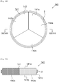
- FIG.1 shows a workpiece unit in a schematic plan view.
- Fig.2 shows the workpiece unit in a schematic cross-sectional view taken along line II-II of Fig.1 .
- Fig.3 shows an area of a holding member in a schematic partial cross-sectional view.
- a workpiece unit (or assembly) 10 has a workpiece body 1, and a holding member 2 arranged at least a part of a side wall of the workpiece body 1.
- a workpiece body 1 is worked for example by a working apparatus.
- a dental product is produced from a workpiece body 1.
- prosthesis such as a ceramic frame, a full-contour crown etc. can be enumerated.
- a dental prosthesis has a tooth crown shape.
- a product for orthodontia e.g., a bracket for orthodontia
- a product for dental implant e.g., an abutment for dental implant
- a holding member 2 assists holding or fixing a workpiece unit 10 in a working apparatus.
- at least a holding member 2 in the workpiece unit 10 is held by the working apparatus.
- a workpiece body 1 has a first face 1a which serves as a face to be worked (to-be-worked face), a second face 1b opposite to the first face 1a, and an outer circumferential portion 1c arranged between the first face 1a and the second face 1b.
- a first face 1a and a second face 1b are parallel or approximately parallel to each other.
- a workpiece body 1 has a plane shape.
- the workpiece unit 10 and the workpiece body 1 have a circular plane shape but are not restricted to a circular one, and rather may have an elliptic, polygonal etc. plane shape.
- a holding member 2 is arranged at least a part of the outer circumferential portion 1c which corresponds to the side face of a workpiece body 1.
- a holding member 2 can cover at least a part of the outer circumferential portion 1c of a workpiece body 1 without interposition of an adhesive (material).
- An inner circumferential portion 2c of a holding member 2 and the outer circumferential portion 1c of a workpiece body 1 are directly contacted with each other at least partly.
- a holding member 2 is arranged continuously along an outer circumferential portion 1c.
- a holding member 2 has a shape corresponding to a plane shape of a workpiece body 1.
- a holding member 2 can have e.g. an annular, toroidal, tubular or ring shape.
- a holding member 2 is arranged over the entire circumference of the side wall of a workpiece body 1.
- a gap (or space) may exist between a holding member 2 and a workpiece body 1.
- a holding member 2 can have a first face 2a which is directed in the same direction as a first face 1a of a workpiece body 1 does, a second face 2b which is directed in the same direction as a second face 1b of the workpiece body 1 does, and an inner circumferential portion 2c which is arranged between the first face 2a and the second face 2b and faces in the direction of the outer circumferential portion 1c of the workpiece body 1.
- a first face 2a of a holding member 2 and a first face 1a of a workpiece body 1 are parallel or approximately parallel to each other.
- a first face 2a of a holding member 2 can exist at a position on a side closer to a second face 1b of a workpiece body 1 than a first face 1a of a workpiece body 1 can.
- a second face 2b of a holding member 2 can exist at a position on a side closer to a first face 1a of a workpiece body 1 than a second face 1b of a workpiece body 1 can. That is, it is preferable that a first face 1a of a workpiece body 1 and a first face 2a of a holding member 2 form a level difference (or a step).
- a second face 1b of a workpiece body 1 and a second face 2b of a holding member 2 form a level difference.
- the thickness t2 of a holding member is thinner than the thickness t1 of a whole workpiece body 1.
- alignment is facilitated when a workpiece unit 10 is fixed to a working apparatus.
- a holding member 2 is arranged centrally at a workpiece body 1 in the thickness direction of the workpiece body 1. That is, it is preferable that the center of a holding member 2 in its thickness direction and the center of a workpiece body 1 in its thickness direction overlap each other. Hereby, alignment is facilitated when a workpiece unit 10 is set in a working apparatus.
- a workpiece unit 10 is symmetrical with respect to the extending direction of a first face 1a and a second face 1b of a workpiece body 1.
- a workpiece unit can be set in a working apparatus such that either one of a first face 1a and a second face 1b of a workpiece body 1 are (independently) directed toward a working tool (in general, toward the upper side).
- the thickness t2 (height in Fig.2 ) of a holding member 2 may be any arbitrary thickness unless the thickness prevents working of a workpiece body 1.
- the thickness t2 of a holding member 2 is thinner than the thickness t1 of a workpiece body 1. This is adopted to facilitate holding a workpiece unit 10 in a working apparatus.
- the thickness t2 of a holding member 2 is preferably 1mm or greater, more preferably 2mm or greater, and even more preferably 4mm or greater. This is adopted to keep the strength for supporting the unit by a working apparatus.
- the width w1 (radial thickness or length) of a holding member 2 may be such a width that allows a workpiece unit 10 to be supported in a working apparatus.
- a material for a workpiece body 1 for example, ceramic, metal, resin etc. can be used.
- the ceramic a material containing at least one of zirconia, alumina and crystallized glass can be enumerated.
- the metal titanium, titanium alloy etc. can be enumerated.
- acrylic resin, methacrylic resin, ABS (acrylonitrile butadiene styrene) resin, polycarbonate, polypropylene, polystyrene, polyester, polyether ketone, Teflon (registered trade mark of polytetrafluoroethylene) etc. can be enumerated.
- a composite material (a composite resin) made from (one of) these resins filled with an inorganic filler(s) can be enumerated as an example of the resin.
- the workpiece body 1 may be a zirconia pre-sintered body fired to such a state that the zirconia crystal grains therein have not completely been sintered.
- the zirconia pre-sintered body contains zirconia and a stabilizing agent which suppresses phase transition of zirconia crystal phase.
- a stabilizing agent when becoming a sintered body, suppresses phase transition of the crystal phase of the sintered body from tetragonal to monoclinic phase.
- oxides such as calcium oxide (CaO), magnesium oxide (MgO), yttrium oxide (Y 2 O 3 ), cerium oxide (CeO 2 ) etc.
- a stabilizing agent is added in such an amount as to enable partial stabilization of tetragonal zirconia grains.
- a stabilizing agent is preferably 2mol% to 8mol%, more preferably 2.5mol% to 6.5mol%, with respect to the total molar number of zirconia and yttria. If a content of a stabilizing agent is excessively increased, phase transition can be suppressed but bending strength and fracture toughness are lowered. In contrast, a too low content of a stabilizing agent can suppress lowering of bending strength and fracture toughness but insufficiently suppresses progression of phase transition.
- zirconia stabilized partially by addition of a stabilizing agent is called a partially stabilized zirconia.
- the content of a stabilizing agent in a zirconia sintered body can be measured by, e.g., inductively coupled plasma (ICP) emission spectrometry, fluorescence X-ray analysis etc.
- ICP inductively coupled plasma
- the size d1 of a whole workpiece body 1 and the thickness t1 of the workpiece body 1 can be determined discretionally in accordance with purposes.
- a material of a holding member 2 is such a material that is not greatly deformed by pressure generated at the time of being fixed to a working apparatus. Further, it is preferable that a material of a holding member 2 is such a material that can be mounted on a workpiece body 1 by a method as explained below.
- a material of a holding member 2 for example, engineering plastic, polypropylene, polystyrene, acryl resin, ABS (acrylonitrile butadiene styrene) resin, polycarbonate, polyester, polyether ketone, Teflon (registered trademark), metal, wood etc. can be used.
- the above examples of the resin can also include a composite material (a composite resin) made from resin filled with an inorganic filler(s).
- a holding member 2 can be provided with information.
- a holding member 2 can be provided at a visible position with information in the form of symbols such as letters, barcodes etc. by means of printing, engraving, a seal etc.
- the information includes, for example, lot number, color tone (shade), contraction factor (shrinkage factor), distinction between upper and lower sides etc.
- a workpiece body 1 is made.
- Partially stabilized zirconia powder which is zirconia particles containing a stabilizing agent is prepared.
- the type and concentration of the stabilizing agent can be selected discretionally.
- a suitable particle size and particle size distribution of zirconia crystal particles are selected discretionally.
- a suitable method can be discretionally selected such as a hydrolysis method, a neutralizing coprecipitation method, an alkoxide method, a solid phase method etc.
- an additive is added to the prepared partially stabilized zirconia powder followed by mixing. Where wet mixing is used, a resulting composition (or formulation) is dried.
- the composition is pressure-formed to a predetermined shape.
- the composition is pressure-formed to the shape of the workpiece body 1.
- the applied pressure may be, for example, 20MPa or more.
- the composition for sintering may be further subjected to CIP (Cold Isostatic Pressing), e.g., under a pressure of 150MPa or more.
- CIP Cold Isostatic Pressing
- the formed body may be worked to a desired shape by cutting, grinding etc.
- the formed body is fired at a temperature which does not sinter the zirconia grains, thereby forming a pre-sintered body.
- a condition for pre-sintering may be, for example, 800 °C to 1200 °C as a pre-sintering temperature and 1 hour to 12 hours as a resident time for keeping the temperature.
- the pre-sintered body may be worked to a desired shape by cutting, grinding etc. For example, instead of (the composition) being formed to the shape of a workpiece body 1 at the time of forming, it may be performed that after completion of a pre-sintered body the pre-sintered body is formed to the shape of a workpiece body 1 (forming of a protrusion portion). Hereby, a workpiece body 1 is manufactured.
- a holding member 2 is prepared.
- a method of making a holding member 2 is not restricted to a specific one.
- a holding member 2 can be made by injection molding, extrusion molding, cutting (machining) etc.
- the holding member of a ring shape 2 is expanded by heating, for example.
- a heating temperature of a holding member 2 can be discretionally determined according to a material of the holding member 2.
- the heating temperature of the holding member 2 is preferably 60°C or greater, more preferably 80°C or greater.
- the heating temperature of a holding member 2 is preferably 150°C or lower, and may be, for example, not higher than 120°C or not higher than 100°C.
- the workpiece body 1 is inserted into the holding member 2 under such a state that the holding member 2 is expanded. Then, the holding member 2 and the workpiece body 1 are aligned, followed by cooling the holding member 2. The holding member 2 is contracted by cooling. Hereby, the holding member 2 is mounted on the workpiece body 1 (a so-called shrinkage-fit operation). According to this method, a holding member 2 is mounted on (or attached to) a workpiece body 1 without using an adhesive.
- Fig.4 and Fig.5 show in a schematic cross-sectional view of a workpiece unit an example of a workpiece unit after a workpiece body 1 is worked.
- Fig.4 is a schematic partial cross-sectional view in an area of a holding member.
- a workpiece unit 10 is set to a working apparatus, and a workpiece body 1 is worked by cutting etc. to form a worked item (or worked article) 4.
- the worked item 4 can be machined under such a state that an outer edge portion 1e of the workpiece body 1 remains in the shape of a frame, and the worked item 4 is connected to the outer edge (or periphery) portion 1e.
- the worked item 4 is, for example, a dental product as described above.
- a cut portion 5 which has been subjected to cutting is formed in the workpiece body 1.
- the outer edge portion 1e is formed along the outer circumferential portion 1c by forming the worked item 4 and the cut portion 5.
- the outer edge portion 1e is a working margin and functions as a frame for the worked item 4.
- the worked item 4 is connected to the outer edge portion 1e via a connection portion 4a.
- the shape of a first positioning portion as described below is preferably of such a shape that does not provide an adverse effect such as falling of the worked item 4 after working.
- a holding member 2 is mounted on a workpiece body 1 without using an adhesive.
- the force generated by the heat expansion of a holding member 2 is not transmitted to the workpiece body 1 via the adhesive, and thus it is possible to suppress occurrence of a problem (e.g., fracture of a workpiece body 1 or a worked item) which results from a difference between thermal expansion coefficients of a workpiece body 1 and a holding member 2.
- the holding member can be easily removed from the workpiece body 1.
- a mold for making the workpiece body 1 can be downsized by the width of the holding member 2, as a result of which an amount of row material used for making the workpiece body 1 can be reduced. If a cost of the workpiece body 1 is higher than that of the holding member 2, production costs of the workpiece unit 10 and the worked item 4 can be reduced.
- FIG.6 shows in a schematic partial cross-sectional view a workpiece unit according to the second exemplary embodiment.
- Fig.7 shows in a schematic exploded cross-sectional view a workpiece body and a holding member.
- a workpiece body 21 has at least one first positioning portion 21d at an area of its outer circumferential portion 1c [sic. 21c] which area faces a holding member 22.
- the holding member 22 has at least one second positioning portion 22d at an area of its inner circumferential portion 22c which area faces a workpiece body 21.
- a first positioning portion 21d and a second positioning portion 22d are portions for determining the position of a holding member 22 with respect to the workpiece body 21.
- the first positioning portion 21d and the second positioning portion 22d can suppress occurrence of positioning deviation of the holding member 22 with respect to the workpiece body 21.
- the first positioning portion 21d and the second positioning portion 22d can be arranged at positions where they correspond to each other.
- the first positioning portion 21d and the second positioning portion 22d can have shapes corresponding to each other.
- the first positioning portion 21d is formed as a concave portion.
- the second positioning portion 22d is formed as a convex portion which fits into the concave portion of the first positioning portion 21d.
- Positions of the first positioning portion 21d and the second positioning portion 22d may be any portions where the outer circumferential portion 21c of the workpiece body 21 and an inner circumferential portion 22c of a holding member 22 face each other.
- a convex portion is such that at least a part thereof can be inserted into a concave portion.
- a convex portion has such a shape and a size that allows it to contact with the opening and/or the inner wall of a concave portion when it is inserted into the concave portion.
- the width e.g., the size in the direction (the vertical direction in the figure) connecting the first face 21a and the second face 21b of the workpiece body 21
- the width e.g., the size in the direction (the vertical direction in the figure) connecting the first face 21a and the second face 21b of the workpiece body 21
- Fig.8 to Fig.11 show in schematic plan views examples of a first positioning portion 21d and a second positioning portion 22d.
- Fig.8 to Fig.11 show (merely) plan views of first positioning portions 21d
- second positioning portions 22d have plane shapes corresponding to the shapes of the first positioning portions 21d.
- illustration and explanation of second positioning portions 22d will be omitted.
- the first positioning portion 21d can be formed as a continuous groove portion as shown for example in Fig.8 and Fig.9 .
- a first positioning portion 21d may be a linear groove portion as shown in Fig.8 , or a zigzag or meander groove portion as shown in Fig.9 .
- a first positioning portion 21d can be formed as a concave portion (e.g.
- a dotted line formed (connecting) of the first positioning portions 21d may be linear as shown in Fig.10 or a zigzag- or meander-fashion as shown in Fig.11 .
- Fig.8 to Fig.11 show first positioning portions 21d having a regular shape, but the first positioning portion 21d may have an irregular shape.
- the first positioning portion 21d and the second positioning portion 22d have one triangular cross section, but the first positioning portion 21d and the second positioning portion 22d can have other cross-sectional shapes.
- Fig.12 to Fig.15 show in schematic partial cross-sectional views examples of the first positioning portion 21d and the second positioning portion 22d.
- the first positioning portion 21d and the second positioning portion 22d can have a polygonal (such as tetragonal etc.) cross section as shown in Fig.12 .
- the first positioning portion 21d can have a semicircular, semielliptical etc. cross-sectional shape (a hemispherical shape).
- the second positioning portion 22d may have a semicircular, semielliptical etc. cross-sectional shape (a hemispherical shape) as the first positioning portion 21d does, or a shape different (a triangular shape in Fig.13 ) from that of the first positioning portion 21d as shown in Fig.13 .
- a part(s) of the second positioning portion 22d may be engaged with the first positioning portion 21d.
- the width w22 of the second positioning portion 22d is greater than the width w21 of the first positioning portion 21d.
- a part of the second positioning portion 22d is inserted into the first positioning portion 21d and the first positioning portion 21d and the second positioning portion 22d are contacted with each other partially at the upper and lower ends (edges) of the first positioning portion 21d.
- an outer circumferential portion 21c of the workpiece body 21 and an inner circumferential portion 22c of the holding member 22 may not be contacted with each other.
- the holding member 22 may be deformed by its contraction and partially contact with an outer circumferential portion 21c of the workpiece body 21 at the upper and lower ends of the inner circumferential portion 22c, for example.
- the first positioning portion 21d and the second positioning portion 22d can have a plurality of concave or convex portions in one cross section.
- the first positioning portion 21d and/or the second positioning portion 22d has such a depth and/or a height that allows the first positioning portion 21d and the second positioning portion 22d to engage with each other.
- the depth and/or the height of the first positioning portion 21d and the second positioning portion 22d can be, for example, 0.5mm or more.
- a method of producing a workpiece unit 20 can be the same as the production method according to the first exemplary embodiment.
- the second exemplary embodiment can have the same or similar effect as the first exemplary embodiment.
- the holding member 22 can be mounted on (or attached to) the workpiece body 21 at a suitable position by joining the first positioning portion 21d and the second positioning portion 22d. Further, also after the holding member 22 is mounted on the workpiece body 21, the first positioning portion 21d and the second positioning portion 22d act as a slip stopper, as a result of which positioning deviation of the holding member 22 with respect to the workpiece body 21 can be suppressed.
- FIG.16 shows in a schematic partial cross-sectional view a workpiece unit according to the third exemplary embodiment.
- the first positioning portion of the workpiece body is a concave portion and the second positioning portion of the holding member is a convex portion.
- the concave portion and the convex portion are arranged at the workpiece body 21 and the holding member 22 in a reverse relationship. That is, a first positioning portion 21f arranged at an outer circumferential portion 21c of a workpiece body 21 is a convex portion.
- a second positioning portion 22f arranged at an inner circumferential portion 22c of a holding member 22 is a concave portion corresponding to the first positioning portion 21f.
- a method of producing a workpiece unit 30 can be the same as the production method according to the first exemplary embodiment.
- the third exemplary embodiment can have the same effect as the first and second exemplary embodiments.
- FIG.17 shows a workpiece unit in a schematic plan view.
- Fig.18 shows in a schematic cross-sectional view the workpiece unit taken along line XVII-XVII of Fig.17 .
- Fig.19 shows in a schematic partial cross-sectional view the workpiece unit at an area of a holding member.
- a workpiece body 41 further has a protrusion portion 41c in addition to the structure of the first exemplary embodiment.
- a holding member 2 is arranged at least a part of the protrusion portion 41c.
- a workpiece body 41 has a first face 41a used as a to-be-worked face, and a second face 41b opposite to the first face 41a.
- a first face 41a and a second face 41b are parallel or approximately parallel to each other.
- the workpiece body 41 has a plane shape.
- the workpiece unit 40 and the workpiece body 41 have circular plane shapes, but are not restricted to a circular shape and may have an elliptic, polygonal etc. plane shape.
- the workpiece body 41 has a protrusion portion 41c along at least a part of the side wall, i.e. at the outer edges of a first face 41a and a second face 41b or an outer circumferential portion 41g between the first face 41a and the second face 41b.
- a protrusion portion 41c is a portion for holding or supporting a workpiece unit 40 in a working apparatus.
- the protrusion portion 41c exists in a region where working is not performed by a working apparatus.
- the protrusion portion 41c is disposed continuously along the entire circumference of an outer circumferential portion 41g of the workpiece body 41. That is, it is preferable that the protrusion portion 41c has a ring or toroidal shape.
- the protrusion portion 41c can have such a formulation as to protrude from the side face of the workpiece body 41.
- a protrusion portion 41c protrudes from between a first face 41a and a second face 41b of a workpiece body 41 in a direction approximately perpendicular to the first face 41a and the second face 41b.
- a protrusion portion 41c exists at an outer circumferential portion 41g of a workpiece body 41 and has such a formulation that the end portion of the workpiece body 41 is thinner than the other portion(s) thereof.
- a protrusion portion 41c can have a third face 41d which is directed in the same direction as the first face 41a does, and a fourth face 41e which is directed in the same direction as the second face 41b does.
- the protrusion portion 41c can have a fifth face 41f which connects the third face 41d and the fourth face 41e.
- the third face 41d and the fourth face 41e are parallel or approximately parallel to each other.
- the third face 41d and the first face 41a are parallel or approximately parallel to each other.
- the fourth face 41e and the second face 41b are parallel or approximately parallel to each other.
- the third face 41d and the fifth face 41f are perpendicular or approximately perpendicular to each other.
- the fourth face 41e and the fifth face 41f are perpendicular or approximately perpendicular to each other.
- the first face 41a and the second face 41b are perpendicular or approximately perpendicular to the fifth face 41f.
- the thickness t12 of the protrusion portion 41c is smaller than the thickness t11 of a whole workpiece body 41. That is, it is preferable that the first face 41a and the third face 41d form a level difference (or a step).
- the second face 41b and the fourth face 41e form a level difference.
- the first face 41a and the third face 41d may be formed in the same plane.
- the second face 41b and the fourth face 41e may be formed in the same plane.
- the thickness t12 of the protrusion portion 41c is preferably 1mm or greater, more preferably 2mm or greater, and still more preferably 4mm or greater. This is adopted to hold (or support) a workpiece unit 40 at the time of working and strengthen (reinforce) the workpiece body 41 after working.
- the width w11 of the protrusion portion 41c is preferably 2mm or smaller, more preferably 1.7mm or smaller, and still more preferably 1.5mm or smaller. The reason is that if the width w11 of a protrusion portion 41c is too great, waste part of a workpiece body 41 is increased. Further, the width w11 of the protrusion portion 41c is preferably 0.3mm or greater, more preferably 0.4mm or greater, still more preferably 0.6mm or greater, and even still more preferably 0.8mm or greater. The reason is that the protrusion portion 41c has a function of strengthening the workpiece body 41 after working, and thus the protrusion portion 41c needs a certain width in order to strengthen the workpiece body 41 after working.
- a protrusion portion 41c is disposed centrally at the workpiece body 41 in the thickness direction of the workpiece body 41. That is, it is preferable that the center of the protrusion portion 41c in its thickness direction overlaps with the center of the workpiece body 41 in its thickness direction.
- alignment is facilitated when a workpiece unit 40 is set to a working apparatus.
- the size d12 of the whole workpiece body 41, and the size d13 of the first face 41a and the second face 41b of the workpiece body 41 used as a to-be-worked face can be discretionally determined according to purposes.
- a holding member 2 is arranged at least a part of the outer side of a protrusion portion 41c.
- the holding member 2 is arranged at least in the protrusion direction of a protrusion portion 41c.
- a holding member 2 is arranged continuously along the fifth face 41f which serves as a side face of a protrusion portion 41c. That is, a holding member 2 can cover at least a part of the fifth face 41f of the protrusion portion 41c.
- the fifth face 41f of the protrusion portion 41c and an inner circumferential portion 2c of a holding member 2 face each other.
- the fifth face 41f of the protrusion portion 41c and the inner circumferential portion 2c of the holding member 2 are in direct contact with each other at least partly.
- the first face 2a of the holding member 2 and the third face 41d of the workpiece body 41 are parallel or approximately parallel to each other.
- the second face 2b of the holding member 2 and the fourth face 41e of the workpiece body 41 are parallel or approximately parallel to each other.
- a third face 41d of the protrusion portion 41c and a first face 2a of the holding member 2 can be formed in the same plane.
- the fourth face 41e of the protrusion portion 41c and a second face 2b of the holding member 2 can be formed in the same plane.
- the thickness t13 of the holding member 2 is identical to the thickness t12 of the protrusion portion 41c.
- the first face 2a of the holding member 2 can exist at a position closer to the first face 41a of the workpiece body 41 than the third face 41d of a protrusion portion 41c can.
- the second face 2b of the holding member 2 can exist at a position closer to the second face 41b of the workpiece body 41 than the fourth face 41e of the protrusion portion 41c can. The reason is that it is facilitated to hold (or support) the workpiece unit 40 in a working apparatus.
- the thickness t13 of the holding member 2 is greater than the thickness t12 of the protrusion portion 41c.
- the thickness t13 of the holding member 2 may be any arbitrary thickness unless the thickness prevents working of the workpiece body 41.
- the thickness t13 of the holding member 2 is preferably smaller than the thickness t1 of the workpiece body 41, and more preferably substantially equivalent to the thickness t12 of the protrusion portion 41c. The reason is that it is facilitated to hold (or support) the workpiece unit in a working apparatus.
- the thickness t13 of the holding member 2 is preferably 1mm or greater, more preferably 2mm or greater, and still more preferably 4mm or greater. The reason is that the strength of holding (or supporting) by the working apparatus is kept.
- the width w12 of the holding member 2 has such a size that a total size of the width w12 and the width w11 of a protrusion portion 41c in the abutted state allows holding (or supporting) in a working apparatus.
- a method of producing the workpiece unit 40 can be the same as the production method according to the first exemplary embodiment.
- Fig.17 to Fig.19 As the formulations of the protrusion portion and the holding member, formulations different from those shown in Fig.17 to Fig.19 can be adopted.
- Fig.20 to Fig.23 show other examples of a protrusion portion and a holding member.
- a holding member 52 is arranged so as to cover not only the fifth face 41f of the protrusion portion 41c, but also at least a part of a third face 41d and a fourth face 41e. That is, the holding member 52 can have on a side directed to the workpiece body 41 a groove portion for accommodating the protrusion portion 41c. The holding member 52 can be arranged so as to fit the protrusion portion 41c into the groove portion.
- the width w14 of the protrusion portion 41c is the same as the width w11 shown in Fig.18 .
- the width (w14+w15) of a holding member 52 is the same as the width (w11+w12) shown in Fig.18 .
- the thickness t14 of the protrusion portion 41c is 1mm or greater in order to secure the strength.
- the thickness t15 of the holding member 52 is equal to or smaller than the thickness of the workpiece body 41 in order to perform holding (or supporting) in a working apparatus.
- a holding member 62 can be arranged so as to cover the fifth face 41f of a protrusion portion 41c and either of the third face 41d and the fourth face 41e thereof.
- the holding member 62 is arranged so as to cover the third face 41d and the fifth face 41f of the protrusion portion 41c.
- the holding member 62 has a first face 62a which is directed in the same direction as the second face 41b of the workpiece body 41 and the fourth face 41e do.
- the holding member 62 is arranged such that the first face 62a is formed in the same plane as the fourth face 41e of the protrusion portion 41c, or exists at a position closer to the second face 41b than the fourth face 41e of the protrusion portion 41c. This aims at stabilizing attachment of the workpiece unit 60 to a working apparatus.
- the holding member 62 is arranged at the workpiece body 41 centrally in its thickness direction. In this case, the position of the protrusion portion 41c can be shifted from the central position of the workpiece body 41 in its thickness direction.
- the width w16 of the protrusion portion 41c is the same as the width w11 shown in Fig.18 .
- the width (w16+w17) of the holding member 62 is the same as the width (w1 [sic.w11] +w2 [sic.w12]) shown in Fig.18 .
- the thickness t16 of a protrusion portion 41c is 1mm or greater in order to secure the strength.
- the thickness t17 of the holding member 62 is equal to or smaller than the thickness of the workpiece body 41 in order to perform holding (or supporting) in a working apparatus.
- a holding member 72 is made up of two or more components.
- Fig.23 is a plan view observed from the side face of the holding member 72.
- the holding member 72 has a first portion 72a which covers a third face 41d of a protrusion portion 41c and a second portion 72b which covers a fourth face 41e of the protrusion portion 41c.
- a fifth face 41f of the protrusion portion 41c is covered (enclosed) with the first portion 72a and the second portion 72b.
- the first portion 72a and the second portion 72b each have at least one engagement portion on the side facing the fifth face 41f of the protrusion portion 41c.
- the first portion 72a and the second portion 72b are arranged such that a concave portion and a convex portion are fitted with each other on the side of the fifth face 41f of the protrusion portion 41c.
- the demarcation line between the first portion 72a and the second portion 72b extends in a meander fashion.
- the first portion 72a and the second portion 72b are such that their regions where the concave portions and the convex portions are formed have the same shape.
- a whole first portion 72a and a whole second portion 72b have the same shape.
- the first portion 72a and the second portion 72b are of the same component. This can simplify production and management of the holding member 72.
- an engagement portion(s) is(are) provided at each portion of the holding member 72, as a result of which positioning deviation of each portion can be prevented.
- the holding member 72 is made up of a plurality of components, as a result of which mounting the holding member 72 on a workpiece body 41 (attaching the holding member 72 to a workpiece body 41) can be made easy.
- the protrusion portion is provided.
- the holding member 2 can be made up of two or more components.
- the fourth exemplary embodiment can have the same effect as the first exemplary embodiment.
- a workpiece body 41 after working is the same as that shown in Fig.4 and Fig.5 .
- a workpiece body 41 after working further has protrusion portion 41c at an outer edge portion 1e.
- a worked item 4 is connected to at least one of an outer edge portion 1e and a protrusion portion 41c.
- the thickness of an outer edge portion of a workpiece body 41 can be partly secured by a protrusion portion 41c. This can suppress fracture of a workpiece body 41 even if, after working, an impact is given to the workpiece body 41. Further, provision of a protrusion portion 41c can enlarge an allowable range of positioning deviation in attachment of a workpiece unit 40 to a working apparatus.
- FIG.24 to Fig.27 show in schematic partial cross-sectional views workpiece units according to the fifth exemplary embodiment.
- Fig.24 to Fig.27 each show an example of the fifth exemplary embodiment.
- first positioning portion and the second positioning portion presented by the second and third exemplary embodiments are applied to the formulation shown in Fig.19 according to the fourth exemplary embodiment.
- a first positioning portion 41h of a workpiece body 41 can be arranged on a fifth face 41f of a protrusion portion 41c.
- a second positioning portion 22d of a holding member 22 can be arranged at a position corresponding to a first positioning portion 41h. Formulations of the first positioning portion 41h and the second positioning portion 22d can be the same as those of the second and third exemplary embodiments.
- first positioning portion and the second positioning portion presented by the second and third exemplary embodiments are applied to the formulation shown in Fig.20 according to the fourth exemplary embodiment.
- a first positioning portion 41h of a workpiece body 41 can be arranged on a fifth face 41f of a protrusion portion 41c.
- a second positioning portion 52a of a holding member 52 can be arranged at a position corresponding to the first positioning portion 41h. Formulations of the first positioning portion 41h and the second positioning portion 52a can be the same as those of the second and third exemplary embodiments.
- first positioning portion and the second positioning portion presented by the second and third exemplary embodiments are applied to the formulation shown in Fig.21 according to the fourth exemplary embodiment.
- a first positioning portion 41h of a workpiece body 41 can be arranged on a fifth face 41f of a protrusion portion 41c.
- a second positioning portion 62b of a holding member 62 can be arranged at a position corresponding to a first positioning portion 41h. Formulations of the first positioning portion 41h and the second positioning portion 62b can be the same as those of the second and third exemplary embodiments.
- first positioning portion and the second positioning portion presented by the second and third exemplary embodiments are applied to the formulation shown in Fig.22 according to the fourth exemplary embodiment.
- a first positioning portion 41h of a workpiece body 41 can be arranged on a fifth face 41f of a protrusion portion 41c.
- a second positioning portion 72c of a holding member 72 can be arranged at a position corresponding to the first positioning portion 41h. Formulations of the first positioning portion 41h and the second positioning portion 72c can be the same as those of the second and third exemplary embodiments.
- the concave portion and the convex portion can be arranged at the workpiece body and the holding member in a reverse relationship, as is the case of the third exemplary embodiment. That is, the first positioning portion arranged at the protrusion portion of the workpiece body can have a convex portion, and the second positioning portion arranged at the inner circumferential portion of the holding member can have a concave portion (whose illustrations are omitted).
- the first positioning portion of the workpiece body exists at the fifth face of the protrusion portion.
- the first positioning portion can be arranged at least one of the third and fourth faces of the protrusion portion.
- the second positioning portion can be arranged at a position corresponding to the first positioning portion.
- a method of producing a workpiece unit according to the fifth exemplary embodiment can be the same as the production method according to the first exemplary embodiment.
- the fifth exemplary embodiment can have the same effect as the first to fourth exemplary embodiments.
- a workpiece body has a plurality of components.
- Fig.28 shows in a schematic plan view a workpiece unit according to the sixth exemplary embodiment.
- Fig.29 shows in a schematic cross-sectional view the workpiece unit taken along line XXVIII-XXVIII of Fig.28 .
- a workpiece body 141 is physically divided into a plurality of sections 142.
- One workpiece body 141 is configured in combination of a plurality of sections 142.
- at least two sections 142 may differ in composition.
- individual sections 142 can contain coloring materials different from one another.
- At least two sections 142 of a plurality of sections 142 can be identical in composition, and all sections 142 may have the same composition.
- Main materials of individual sections 142 may be identical to or different from one another.
- one section 142 is smaller than such a size that it can be held or fixed in a working apparatus.
- At least one of a plurality of sections 142 can be a part which is worked by a working apparatus. At least one of a plurality of sections 142 can be a part which is not worked by a working apparatus. At least one of a plurality of sections 142 can be a dummy workpiece body for compensating for a size (or shape) of a workpiece body 141 thereby making the workpiece body 141 have such a size that it can be held in a working apparatus.
- a workpiece body 141 is divided by individual sections 142 so as to divide a first face 141a and a second face 141b of the workpiece body 141.
- the number of sections 142 in a workpiece body 141 can be determined discretionally.
- a size of one section 142 can be discretionally adjusted according to demand etc. such as an individual composition etc.
- a plurality of sections 142 may differ in size or have the same size.
- At least one section 142 can have at least a part of a protrusion portion 141c of a workpiece body 141.
- the formulation of a protrusion portion 141c can be the same as those of the above exemplary embodiments.
- a protrusion portion 141c can be connected by combining a plurality of sections 142.
- a shape of each section 142 may be an any arbitrary one.
- a plurality of sections 142 may differ in shape or have the same shape.
- the workpiece body 141 is so divided that (boundary of) a section(s) 142 pass(es) through the center of the circle.
- a section(s) 142 can have a fan-like plane shape(s).
- the radiuses of the fan shapes are identical to each other.
- a workpiece body 141 having a circular or elliptic shape can be formed by combining (or assembling) a plurality of sections 142 in a radial manner such that the individual arcs thereof are connected in a consecutive manner.
- the total of the central angles of a plurality of sections 142 is 360°.
- Each fan-shape may have an arbitrary central angle, which can be, for example, 45°, 60°, 90°, 120°, 180° (i.e. a semi-circle, semi-ellipse etc.), 240°, 270°, 300°, 315° etc.
- a plurality of sections 142 have the same thickness.
- both a first face 141a and a second face 141b can be formed as a plane. Further, this facilitates alignment in the thickness direction when a workpiece unit 140 is fixed in a working apparatus.
- a workpiece body 141 has a first section 142a, a second section 142b, and a third section 142c.
- the first section 142a, the second section 142b and the third section 142c have the same shape.
- the first section 142a, the second section 142b and the third section 142c have the same size.
- the first section 142a, the second section 142b and the third section 142c have a plane shape both faces of which are of a fan shape.
- the central angle of the fan shape is 120°.
- Fig.30 to Fig.33 show in schematic plan views workpiece bodies presenting examples of plane shapes of sections.
- Fig.30 to Fig.33 show states in which sections from which one workpiece body is assembled are separated from each other.
- sections 142a, 142b, 142c have a fan-like plane shape having a central angle of 120°.
- sections 142a, 142b have a semi-circular plane shape.
- a section 142a has a semi-circular plane shape whereas sections 142b, 142c have a fan-like plane shape having a central angle of 90°.
- the radiuses of the individual sections are of the same size.
- sections 142a-f do not have a fan-like plane shape but are formed so as to make up a circular shape in the assembled state.
- Fig.34 shows in a schematic plan view a workpiece body presenting another formulation of a workpiece body.
- the sections 142 may be in direct contact with each other.
- a workpiece body 141 may further have a buffer (or a buffering material) 143 in at least a part between the adjacent sections 142.
- a buffer 143 is such a material that is able to absorb irregularities at the end face of sections 142.
- a buffer 143 may be an adhesive which joins sections 142.
- a resin sheet for example, may be used.
- a buffer 143 provided totally between sections 142 is shown.
- a buffer 143 may be provided partially between sections 142. Use of a buffer 143 makes it possible to suppress poor alignment caused by irregularities at the end faces of sections 142 when they are combined (or assembled). Further, use of an adhesive as a buffer 143 makes it possible to increase the strength for junction of sections 142.
- Fig.35 shows in a schematic side view a workpiece body presenting another formulation of a workpiece body.
- a section 142 can have an engagement portion which engages with an adjacent section 142 at the end face which faces the adjacent section 142.
- an engagement portion can be formed for example as a concave portion 142g which is formed at the end face of a section 142a, and a convex portion 142h which is formed at the end face of a section 142b and engages with the concave portion 142g.
- a workpiece body 141 may further have a buffer 143 as shown in Fig.34 in addition to engagement portions. Provision of engagement portions makes it possible to increase the strength for junction of sections 142.
- a section 142 is a section which is not worked (a dummy workpiece body)
- any arbitrary material of such strength that allows a workpiece unit 140 to be held in a working apparatus and permits a section 142 for working to be worked can be used in addition to the above mentioned materials, as a material of the section 142 which is not worked.
- the sixth exemplary embodiment can have the same effect as the first to fifth exemplary embodiments.
- a workpiece body can have a plurality of sections which differ in composition. Each section can be adjusted as to its size and shape according to needs. This makes it possible to increase an efficiency of use of a workpiece body and reduce waste portions of a workpiece body. Further, a workpiece body can be produced and sold on a section basis. Moreover, a worked item having different compositions can be produced by using a working apparatus in a single operation.
- FIG.36 shows in a schematic plan view a workpiece unit in the seventh exemplary embodiment.
- Fig.37 shows in a schematic plan view a section unit in the seventh exemplary embodiment.
- one holding member is applied to the sections whereas in the seventh exemplary embodiment a part of a holding member is arranged for each section.
- a workpiece unit 150 according to the seventh exemplary embodiment has a plurality of section units 151.
- Each section unit 151 has a section 142 and a covering member 152 which is arranged at least the side face of the section 142.
- a section 142 can be the same as that of the sixth exemplary embodiment.
- a size of one section unit 151 can be smaller than a size which allows it to be held in a working apparatus.
- a covering member 152 encloses an outer circumferential portion (a side face) of a section 142.
- the covering member 152 can be the same as the holding member in the first to sixth exemplary embodiments except that it encloses one section.
- the covering members 152 form a holding member which is held by a working apparatus.
- a part of one covering member 152 forms a part of the holding member.
- the parts of the covering members 152 are connected to form a holding member which encloses the combination of the sections 142.
- a portion of the covering member 152 which is arranged at the arc portion of the section 142 constitutes a holding member.
- a portion of the covering member 152 which does not constitute a holding member can function as a buffer portion which makes junction between adjacent sections smooth.
- Section units 151 can be joined to each other with an adhesive (not shown).
- engagement portions which engage covering members 152 with each other may be provided at an area where the covering members 152 face each other.
- Fig.38 shows in a schematic plan view a section unit of a formulation different from the formulation shown in Fig.37 .
- a covering member is arranged over the entire periphery of a section.
- a covering member 154 is arranged merely at a part of the side face of a section 142.
- Section units 153 can make up a workpiece unit as shown in Fig.28 by being assembled in the same manner as shown in Fig.36 .
- a covering member 154 is arranged at a portion where it acts as a holding member by assembling section units.
- the covering member 154 is arranged along the arc portion of the section 142. A portion of the side face of the section 142 which portion faces the adjacent section 142 in assembly of the section units 153 is not provided with a covering member 154.
- the section unit 153 shown in Fig.38 has the same formulation of the section unit shown in Fig.37 , except that the position where the covering member 154 is arranged is different.
- Section units 153 can be jointed to each other with an adhesive (not shown).
- engagement portions which engage sections 142 with each other may be provided at an area where the sections 142 face each other.
- the seventh exemplary embodiment can have the same effect as the first to sixth exemplary embodiments. Because the section units can be produced or sold independently, a user can produce or buy a section unit according to the needs to arbitrarily determine a combination of compositions in a workpiece unit.
- FIG.39 shows in a schematic plan view a workpiece unit in the eighth exemplary embodiment.
- Fig.40 shows in a schematic plan view a dummy workpiece body in the eighth exemplary embodiment.
- the workpiece unit is composed by assembling a plurality of section units.
- a workpiece unit 160 is composed using one section unit.
- a workpiece unit 160 has a section unit 151 and a dummy workpiece body 161.
- a section unit 151 is the same as the section unit 151 according to the seventh exemplary embodiment.
- a dummy workpiece body 161 compensates for a size (or shape) of the section unit 151 and allows the section unit 151 to be held in a working apparatus.
- a dummy workpiece body 161 can have a holding portion 161a for being held in a working apparatus.
- the holding portion 161a has the same function as a holding member.
- the holding portion 161a may be formed integrally as a part of a dummy workpiece body 161 or as a separate member thereof.
- the dummy workpiece body 161 has such a plane shape that three section units 151 are assembled.
- the dummy workpiece body 161 has such a plane shape as to form a circle by being assembled with the section unit 151.
- a shape and a size of a dummy workpiece body 161 can be designed according to a shape and size of a section unit 151.
- a dummy workpiece unit 161 has such a thickness that it can be held in a working apparatus.
- Material of a dummy workpiece body 161 may be any arbitrary material which allows a section to be held and worked in a working apparatus. As the material of a dummy workpiece body 161, the same material as that of a holding member can be used, for example.
- a dummy workpiece body 161 and a section unit 151 can be jointed to each other with an adhesive (not shown).
- engagement portions which engage a dummy workpiece body 161 and a section unit 151 with each other may be provided at an area where the dummy workpiece body 161 and the section unit 151 face each other.
- the dummy workpiece body 161 can be used repeatedly.
- the section unit 151 is attachable to and removable from a dummy workpiece body 161.
- Fig.41 shows in a schematic plan view a workpiece unit of a formulation different from the formulation shown in Fig.39 .
- a workpiece unit 163 has a section (a workpiece body) 144, a dummy workpiece body 164 to hold the section 144, and an adhesive 145 to join the section 144 and the dummy workpiece body 164.
- the dummy workpiece body 164 has a toroidal or tubular structure which has an opening formed (cut out) in a size of the section 144.
- the dummy workpiece body 164 can have a holding portion 164a for holding in a working apparatus.
- a size (e.g. a radius) of a section 144 can be 80% or smaller, 60% or smaller, 50% or smaller, or 40% or smaller of a size which allows it to be held in a working apparatus.
- the dummy workpiece body 164 has such a strength that allows it not to be deformed when being worked by a working apparatus.
- the eighth exemplary embodiment can have the same effect as the first to seventh exemplary embodiments. In is unnecessary to size the workpiece body up to such an extent that it can be held (or supported) in a working apparatus. Hereby, even a composition having a low demand can be worked with no need of a workpiece body(s) of other composition(s).
- a workpiece unit (or assembly) according to a ninth exemplary embodiment of the present disclosure will be explained.
- the sections are physically separated from each other.
- at least two sections in a workpiece body cannot be physically separated and formed integrally.
- a schematic plan view and a schematic cross-sectional view of a workpiece unit in the ninth exemplary embodiment can be the same as those of Fig.28 and Fig.29 .
- adjacent sections 142 are connected with each other. Accordingly, it is preferable that materials of adjacent sections 142 are those which can be connected (or bound) to each other by firing, and are identical in main material.
- adjacent sections 142 can be zirconia which are different from each other in type and/or content of an additive such as a coloring agent etc.
- a method of producing a workpiece body according to the ninth exemplary embodiment is the same as the production method according to the above exemplary embodiment(s) except that a plurality of sections are formed integrally.
- a workpiece body is formed as follows. First, removable partition(s) is(are) provided in a mold, thereby forming a mold for sections of a desired shape(s). The partition(s) is(are) located on the boundary(boundaries) between the sections. Next, a composition (or formulation) is provided in the area of each section, followed by removing the partition(s). Then, the compositions (or formulations) are formed under pressure, as a result of which a formed body made from the integrated plural compositions can be formed.
- a method performed after the firing of the formed body is the same as in the above exemplary embodiment.
- the ninth exemplary embodiment can have the same effect as the first to eighth exemplary embodiments. Further, a member for holding a plurality of sections such as a holding member, an adhesive etc. is not necessary.
- the workpiece unit and the production method according to the present invention are described based on the above-described exemplary embodiments but not restricted thereto. Rather, it is possible for the workpiece unit and the production method to include various types of variations, modifications or improvements of a wide variety of the disclosed elements (including the individual elements of the individual claims, the individual elements of the individual exemplary embodiments or examples, the individual elements of the individual figures etc.) within the whole disclosure of the present invention (including the Claims and the Drawings) and based on the basic technical concept of the present invention.
- the present disclosure is applicable to, e.g., production of dental prosthesis.
Landscapes
- Health & Medical Sciences (AREA)
- Veterinary Medicine (AREA)
- Animal Behavior & Ethology (AREA)
- Epidemiology (AREA)
- Life Sciences & Earth Sciences (AREA)
- Oral & Maxillofacial Surgery (AREA)
- General Health & Medical Sciences (AREA)
- Dentistry (AREA)
- Public Health (AREA)
- Engineering & Computer Science (AREA)
- Mechanical Engineering (AREA)
- Chemical & Material Sciences (AREA)
- Ceramic Engineering (AREA)
- Orthopedic Medicine & Surgery (AREA)
- Dental Prosthetics (AREA)
- Finish Polishing, Edge Sharpening, And Grinding By Specific Grinding Devices (AREA)
- Jigs For Machine Tools (AREA)
Claims (13)
- Unité de pièce à usiner (10), comprenant :un corps de pièce à usiner (1), et un organe de retenue (2) de forme annulaire qui est disposé sur au moins une partie d'une portion circonférentielle extérieure (2c) du corps de pièce à usiner et qui vient en contact direct avec au moins une partie de la portion circonférentielle extérieure (2c),caractérisée en ce que :l'organe de retenue est attaché au corps de pièce à usiner sans adhésif, etl'organe de retenue est disposé centralement dans la direction de l'épaisseur (t1) du corps de pièce à usiner.
- Unité de pièce à usiner selon la revendication 1, dans laquelle l'organe de retenue est disposé en continu le long de la portion circonférentielle extérieure.
- Unité de pièce à usiner selon la revendication 1 ou 2, dans laquelle l'organe de retenue a une forme annulaire.
- Unité de pièce à usiner selon l'une des revendications 1 à 3, dans laquelle l'organe de retenue à une plus petite épaisseur que le corps de pièce à usiner.
- Unité de pièce à usiner selon l'une des revendications 1 à 4, dans laquelle l'organe de retenue est constitué de deux ou plus de deux composants.
- Unité de pièce à usiner selon la revendication 5, dans laquelle chacun des composants individuels de l'organe de retenue présente une portion concave ou convexe, et
les composants individuels sont disposés de telle sorte que la portion concave et la portion convexe soient ajustées l'une à l'autre. - Unité de pièce à usiner selon l'une des revendications 1 à 6, dans laquelle le corps de pièce à usiner est en céramique, en métal ou en résine.
- Unité de pièce à usiner selon l'une des revendications 1 à 7, dans laquelle le corps de pièce à usiner est un corps pré-fritté dans lequel des grains de cristaux de zircone n'ont pas été complètement frittés.
- Unité de pièce à usiner selon l'une des revendications 1 à 8, dans laquelle l'organe de retenue est en plastique.
- Unité de pièce à usiner selon l'une des revendications 1 à 9, dans laquelle le corps de pièce à usiner a au moins un article usiné qui est formé en usinant le corps de pièce à usiner et qui est connecté à une portion de bord extérieur du corps de pièce à usiner.
- Procédé de production d'une unité de pièce à usiner selon la revendication 1, comprenant les étapes suivantes :préparer un corps de pièce à usiner (1),préparer un organe de retenue (2) de forme annulaire,caractérisé en ce que le procédé comprend en outre les étapes suivantes :dilater l'organe de retenue (2) par chauffage,insérer le corps de pièce à usiner (1) dans l'anneau de l'organe de retenue (2), et monter l'organe de retenue (2) au niveau de la portion circonférentielle extérieure du corps de pièce à usiner (1) en contractant le corps de retenue par refroidissement.
- Procédé de production d'une unité de pièce à usiner selon la revendication 11, dans lequel à l'étape de dilatation de l'organe de retenue, l'organe de retenue est chauffé entre 60°C et 150°C.
- Procédé de production d'une unité de pièce à usiner selon la revendication 11 ou 12, dans lequel l'organe de retenue comprend du plastique d'ingénierie.
Applications Claiming Priority (2)
| Application Number | Priority Date | Filing Date | Title |
|---|---|---|---|
| JP2015056570 | 2015-03-19 | ||
| PCT/JP2016/058765 WO2016148287A1 (fr) | 2015-03-19 | 2016-03-18 | Unité à façonner, et procédé de fabrication de celle-ci |
Publications (3)
| Publication Number | Publication Date |
|---|---|
| EP3272306A1 EP3272306A1 (fr) | 2018-01-24 |
| EP3272306A4 EP3272306A4 (fr) | 2018-10-10 |
| EP3272306B1 true EP3272306B1 (fr) | 2020-06-10 |
Family
ID=56918928
Family Applications (1)
| Application Number | Title | Priority Date | Filing Date |
|---|---|---|---|
| EP16765116.5A Active EP3272306B1 (fr) | 2015-03-19 | 2016-03-18 | Unité à façonner, et procédé de fabrication de celle-ci |
Country Status (4)
| Country | Link |
|---|---|
| US (2) | US11109948B2 (fr) |
| EP (1) | EP3272306B1 (fr) |
| JP (2) | JP7075756B2 (fr) |
| WO (1) | WO2016148287A1 (fr) |
Families Citing this family (5)
| Publication number | Priority date | Publication date | Assignee | Title |
|---|---|---|---|---|
| WO2016148287A1 (fr) * | 2015-03-19 | 2016-09-22 | クラレノリタケデンタル株式会社 | Unité à façonner, et procédé de fabrication de celle-ci |
| FR3088536B1 (fr) * | 2018-11-15 | 2022-05-27 | Lyra France | Ebauche pour la fabrication sur mesure d'au moins deux elements prothetiques dentaires |
| JP7485328B2 (ja) * | 2019-12-03 | 2024-05-16 | 株式会社DentalBank | 歯科用被切削体 |
| JP7403153B2 (ja) | 2020-01-27 | 2023-12-22 | 株式会社トクヤマデンタル | 加工用ブロック |
| KR102432438B1 (ko) * | 2020-08-21 | 2022-08-16 | 주식회사 하스 | 치과용 블랭크 |
Family Cites Families (22)
| Publication number | Priority date | Publication date | Assignee | Title |
|---|---|---|---|---|
| JPS61146404A (ja) | 1984-12-21 | 1986-07-04 | Fujitsu Ltd | 旋盤用チヤツク機構 |
| JP2501809Y2 (ja) * | 1989-08-16 | 1996-06-19 | ソニー株式会社 | ウエハ―保持装置 |
| EP0759728B1 (fr) | 1994-05-05 | 1997-10-08 | Joseph Hintersehr | Procede et dispositif de fabrication d'une prothese dentaire |
| EP1292241B1 (fr) | 2000-06-22 | 2008-06-25 | 3M Espe AG | Dispositif de fabrication de pieces dentaires |
| ES2327028T3 (es) * | 2000-12-07 | 2009-10-23 | Eidgenossische Technische Hochschule Zurich Nichtmetallische Werkstoffe | Dispositivo de retencion para una pieza bruta ceramica. |
| ES2360797T3 (es) | 2003-04-04 | 2011-06-09 | Xawex Ag | Pieza bruta para la fabricación de reconstrucciones dentales y procedimiento para su fabricación. |
| DE20316004U1 (de) * | 2003-10-14 | 2004-03-04 | Stührenberg, Birgit | Rohling für die Herstellung von Zahnersatz |
| DE102007013675B4 (de) | 2007-03-19 | 2011-01-13 | Doceram Gmbh | Halterung für keramische Rohlinge |
| DE102007043837B4 (de) * | 2007-09-14 | 2014-02-13 | Ivoclar Vivadent Ag | Rohlinganordnung |
| DE202010001125U1 (de) | 2010-01-22 | 2010-04-08 | Heimatec Gmbh | Vorrichtung zum Halten von zur Herstellung von Zahnersatzteilen dienenden Rohlingen |
| DE102010035669A1 (de) * | 2010-08-27 | 2012-03-01 | Datron Ag | Werkzeugmaschine |
| JP5887119B2 (ja) | 2011-12-06 | 2016-03-16 | 株式会社パイロットコーポレーション | 切削焼結用セラミックス仮焼材料およびその製造方法 |
| DE102012201744A1 (de) * | 2012-02-06 | 2013-08-08 | Wieland Dental + Technik Gmbh & Co. Kg | Werkstücksystem |
| JP6352593B2 (ja) * | 2013-05-02 | 2018-07-04 | クラレノリタケデンタル株式会社 | ジルコニア焼結体、ジルコニア組成物及びジルコニア仮焼体、並びに歯科用補綴物 |
| CN107417274B (zh) | 2013-05-10 | 2021-06-18 | 可乐丽则武齿科株式会社 | 氧化锆烧结体、氧化锆组合物和氧化锆煅烧体和它们的制造方法、以及牙科用修复物 |
| DE202013103515U1 (de) * | 2013-08-05 | 2013-09-12 | Ivoclar Vivadent Ag | Rohlingaufnahme sowie Dental-Fräsmaschine |
| DE102015100666A1 (de) | 2015-01-19 | 2016-07-21 | Dentsply International Inc. | Halterung für einen Rohling |
| WO2016148287A1 (fr) * | 2015-03-19 | 2016-09-22 | クラレノリタケデンタル株式会社 | Unité à façonner, et procédé de fabrication de celle-ci |
| KR102460766B1 (ko) * | 2015-03-19 | 2022-10-28 | 쿠라레 노리타케 덴탈 가부시키가이샤 | 피가공 유닛 |
| EP3272308A4 (fr) * | 2015-03-19 | 2018-10-17 | Kuraray Noritake Dental Inc. | Unité à façonner, et procédé de fabrication de celle-ci |
| US20180064515A1 (en) * | 2015-03-19 | 2018-03-08 | Kuraray Noritake Dental Inc. | Workpiece unit and producing method thereof |
| DE202016007641U1 (de) * | 2016-12-19 | 2018-03-20 | Isel Facility GmbH | Blank-Halter einer Dentalfräsmaschine |
-
2016
- 2016-03-18 WO PCT/JP2016/058765 patent/WO2016148287A1/fr active Application Filing
- 2016-03-18 US US15/559,335 patent/US11109948B2/en active Active
- 2016-03-18 JP JP2017506222A patent/JP7075756B2/ja active Active
- 2016-03-18 EP EP16765116.5A patent/EP3272306B1/fr active Active
-
2020
- 2020-07-21 JP JP2020124678A patent/JP7136850B2/ja active Active
-
2021
- 2021-03-11 US US17/199,382 patent/US20210298880A1/en active Pending
Non-Patent Citations (1)
| Title |
|---|
| None * |
Also Published As
| Publication number | Publication date |
|---|---|
| EP3272306A4 (fr) | 2018-10-10 |
| US11109948B2 (en) | 2021-09-07 |
| EP3272306A1 (fr) | 2018-01-24 |
| JPWO2016148287A1 (ja) | 2018-01-18 |
| JP7136850B2 (ja) | 2022-09-13 |
| JP2020179225A (ja) | 2020-11-05 |
| US20210298880A1 (en) | 2021-09-30 |
| WO2016148287A1 (fr) | 2016-09-22 |
| JP7075756B2 (ja) | 2022-05-26 |
| US20180110598A1 (en) | 2018-04-26 |
Similar Documents
| Publication | Publication Date | Title |
|---|---|---|
| EP3272306B1 (fr) | Unité à façonner, et procédé de fabrication de celle-ci | |
| EP3272307B1 (fr) | Unité à façonner, et procédé de fabrication de celle-ci | |
| JP7101731B2 (ja) | 被加工ユニット | |
| JP7146856B2 (ja) | 被加工ユニット及びその製造方法 |
Legal Events
| Date | Code | Title | Description |
|---|---|---|---|
| STAA | Information on the status of an ep patent application or granted ep patent |
Free format text: STATUS: THE INTERNATIONAL PUBLICATION HAS BEEN MADE |
|
| PUAI | Public reference made under article 153(3) epc to a published international application that has entered the european phase |
Free format text: ORIGINAL CODE: 0009012 |
|
| STAA | Information on the status of an ep patent application or granted ep patent |
Free format text: STATUS: REQUEST FOR EXAMINATION WAS MADE |
|
| 17P | Request for examination filed |
Effective date: 20171019 |
|
| AK | Designated contracting states |
Kind code of ref document: A1 Designated state(s): AL AT BE BG CH CY CZ DE DK EE ES FI FR GB GR HR HU IE IS IT LI LT LU LV MC MK MT NL NO PL PT RO RS SE SI SK SM TR |
|
| AX | Request for extension of the european patent |
Extension state: BA ME |
|
| DAV | Request for validation of the european patent (deleted) | ||
| DAX | Request for extension of the european patent (deleted) | ||
| A4 | Supplementary search report drawn up and despatched |
Effective date: 20180912 |
|
| RIC1 | Information provided on ipc code assigned before grant |
Ipc: B24B 41/06 20120101ALI20180906BHEP Ipc: A61C 13/00 20060101ALI20180906BHEP Ipc: A61C 13/083 20060101ALI20180906BHEP Ipc: B23P 11/02 20060101ALI20180906BHEP Ipc: A61C 7/14 20060101ALI20180906BHEP Ipc: A61C 8/00 20060101ALI20180906BHEP Ipc: B23Q 3/10 20060101ALI20180906BHEP Ipc: A61C 13/003 20060101AFI20180906BHEP Ipc: A61C 5/77 20170101ALI20180906BHEP |
|
| RIC1 | Information provided on ipc code assigned before grant |
Ipc: B24B 41/06 20120101ALI20180906BHEP Ipc: A61C 8/00 20060101ALI20180906BHEP Ipc: A61C 7/14 20060101ALI20180906BHEP Ipc: A61C 5/77 20170101ALI20180906BHEP Ipc: B23P 11/02 20060101ALI20180906BHEP Ipc: A61C 13/083 20060101ALI20180906BHEP Ipc: A61C 13/003 20060101AFI20180906BHEP Ipc: A61C 13/00 20060101ALI20180906BHEP Ipc: B23Q 3/10 20060101ALI20180906BHEP |
|
| GRAP | Despatch of communication of intention to grant a patent |
Free format text: ORIGINAL CODE: EPIDOSNIGR1 |
|
| STAA | Information on the status of an ep patent application or granted ep patent |
Free format text: STATUS: GRANT OF PATENT IS INTENDED |
|
| INTG | Intention to grant announced |
Effective date: 20200103 |
|
| GRAS | Grant fee paid |
Free format text: ORIGINAL CODE: EPIDOSNIGR3 |
|
| GRAA | (expected) grant |
Free format text: ORIGINAL CODE: 0009210 |
|
| STAA | Information on the status of an ep patent application or granted ep patent |
Free format text: STATUS: THE PATENT HAS BEEN GRANTED |
|
| AK | Designated contracting states |
Kind code of ref document: B1 Designated state(s): AL AT BE BG CH CY CZ DE DK EE ES FI FR GB GR HR HU IE IS IT LI LT LU LV MC MK MT NL NO PL PT RO RS SE SI SK SM TR |
|
| REG | Reference to a national code |
Ref country code: GB Ref legal event code: FG4D |
|
| REG | Reference to a national code |
Ref country code: CH Ref legal event code: EP Ref country code: AT Ref legal event code: REF Ref document number: 1278623 Country of ref document: AT Kind code of ref document: T Effective date: 20200615 |
|
| REG | Reference to a national code |
Ref country code: DE Ref legal event code: R096 Ref document number: 602016037914 Country of ref document: DE |
|
| REG | Reference to a national code |
Ref country code: IE Ref legal event code: FG4D |
|
| REG | Reference to a national code |
Ref country code: NL Ref legal event code: FP |
|
| REG | Reference to a national code |
Ref country code: LT Ref legal event code: MG4D |
|
| PG25 | Lapsed in a contracting state [announced via postgrant information from national office to epo] |
Ref country code: GR Free format text: LAPSE BECAUSE OF FAILURE TO SUBMIT A TRANSLATION OF THE DESCRIPTION OR TO PAY THE FEE WITHIN THE PRESCRIBED TIME-LIMIT Effective date: 20200911 Ref country code: FI Free format text: LAPSE BECAUSE OF FAILURE TO SUBMIT A TRANSLATION OF THE DESCRIPTION OR TO PAY THE FEE WITHIN THE PRESCRIBED TIME-LIMIT Effective date: 20200610 Ref country code: SE Free format text: LAPSE BECAUSE OF FAILURE TO SUBMIT A TRANSLATION OF THE DESCRIPTION OR TO PAY THE FEE WITHIN THE PRESCRIBED TIME-LIMIT Effective date: 20200610 Ref country code: NO Free format text: LAPSE BECAUSE OF FAILURE TO SUBMIT A TRANSLATION OF THE DESCRIPTION OR TO PAY THE FEE WITHIN THE PRESCRIBED TIME-LIMIT Effective date: 20200910 Ref country code: LT Free format text: LAPSE BECAUSE OF FAILURE TO SUBMIT A TRANSLATION OF THE DESCRIPTION OR TO PAY THE FEE WITHIN THE PRESCRIBED TIME-LIMIT Effective date: 20200610 |
|
| PG25 | Lapsed in a contracting state [announced via postgrant information from national office to epo] |
Ref country code: BG Free format text: LAPSE BECAUSE OF FAILURE TO SUBMIT A TRANSLATION OF THE DESCRIPTION OR TO PAY THE FEE WITHIN THE PRESCRIBED TIME-LIMIT Effective date: 20200910 Ref country code: HR Free format text: LAPSE BECAUSE OF FAILURE TO SUBMIT A TRANSLATION OF THE DESCRIPTION OR TO PAY THE FEE WITHIN THE PRESCRIBED TIME-LIMIT Effective date: 20200610 Ref country code: LV Free format text: LAPSE BECAUSE OF FAILURE TO SUBMIT A TRANSLATION OF THE DESCRIPTION OR TO PAY THE FEE WITHIN THE PRESCRIBED TIME-LIMIT Effective date: 20200610 Ref country code: RS Free format text: LAPSE BECAUSE OF FAILURE TO SUBMIT A TRANSLATION OF THE DESCRIPTION OR TO PAY THE FEE WITHIN THE PRESCRIBED TIME-LIMIT Effective date: 20200610 |
|
| REG | Reference to a national code |
Ref country code: AT Ref legal event code: MK05 Ref document number: 1278623 Country of ref document: AT Kind code of ref document: T Effective date: 20200610 |
|
| PG25 | Lapsed in a contracting state [announced via postgrant information from national office to epo] |
Ref country code: AL Free format text: LAPSE BECAUSE OF FAILURE TO SUBMIT A TRANSLATION OF THE DESCRIPTION OR TO PAY THE FEE WITHIN THE PRESCRIBED TIME-LIMIT Effective date: 20200610 |
|
| PG25 | Lapsed in a contracting state [announced via postgrant information from national office to epo] |
Ref country code: AT Free format text: LAPSE BECAUSE OF FAILURE TO SUBMIT A TRANSLATION OF THE DESCRIPTION OR TO PAY THE FEE WITHIN THE PRESCRIBED TIME-LIMIT Effective date: 20200610 Ref country code: EE Free format text: LAPSE BECAUSE OF FAILURE TO SUBMIT A TRANSLATION OF THE DESCRIPTION OR TO PAY THE FEE WITHIN THE PRESCRIBED TIME-LIMIT Effective date: 20200610 Ref country code: SM Free format text: LAPSE BECAUSE OF FAILURE TO SUBMIT A TRANSLATION OF THE DESCRIPTION OR TO PAY THE FEE WITHIN THE PRESCRIBED TIME-LIMIT Effective date: 20200610 Ref country code: PT Free format text: LAPSE BECAUSE OF FAILURE TO SUBMIT A TRANSLATION OF THE DESCRIPTION OR TO PAY THE FEE WITHIN THE PRESCRIBED TIME-LIMIT Effective date: 20201012 Ref country code: CZ Free format text: LAPSE BECAUSE OF FAILURE TO SUBMIT A TRANSLATION OF THE DESCRIPTION OR TO PAY THE FEE WITHIN THE PRESCRIBED TIME-LIMIT Effective date: 20200610 Ref country code: ES Free format text: LAPSE BECAUSE OF FAILURE TO SUBMIT A TRANSLATION OF THE DESCRIPTION OR TO PAY THE FEE WITHIN THE PRESCRIBED TIME-LIMIT Effective date: 20200610 Ref country code: RO Free format text: LAPSE BECAUSE OF FAILURE TO SUBMIT A TRANSLATION OF THE DESCRIPTION OR TO PAY THE FEE WITHIN THE PRESCRIBED TIME-LIMIT Effective date: 20200610 |
|
| PG25 | Lapsed in a contracting state [announced via postgrant information from national office to epo] |
Ref country code: PL Free format text: LAPSE BECAUSE OF FAILURE TO SUBMIT A TRANSLATION OF THE DESCRIPTION OR TO PAY THE FEE WITHIN THE PRESCRIBED TIME-LIMIT Effective date: 20200610 Ref country code: SK Free format text: LAPSE BECAUSE OF FAILURE TO SUBMIT A TRANSLATION OF THE DESCRIPTION OR TO PAY THE FEE WITHIN THE PRESCRIBED TIME-LIMIT Effective date: 20200610 Ref country code: IS Free format text: LAPSE BECAUSE OF FAILURE TO SUBMIT A TRANSLATION OF THE DESCRIPTION OR TO PAY THE FEE WITHIN THE PRESCRIBED TIME-LIMIT Effective date: 20201010 |
|
| REG | Reference to a national code |
Ref country code: DE Ref legal event code: R097 Ref document number: 602016037914 Country of ref document: DE |
|
| PLBE | No opposition filed within time limit |
Free format text: ORIGINAL CODE: 0009261 |
|
| STAA | Information on the status of an ep patent application or granted ep patent |
Free format text: STATUS: NO OPPOSITION FILED WITHIN TIME LIMIT |
|
| PG25 | Lapsed in a contracting state [announced via postgrant information from national office to epo] |
Ref country code: DK Free format text: LAPSE BECAUSE OF FAILURE TO SUBMIT A TRANSLATION OF THE DESCRIPTION OR TO PAY THE FEE WITHIN THE PRESCRIBED TIME-LIMIT Effective date: 20200610 |
|
| 26N | No opposition filed |
Effective date: 20210311 |
|
| PG25 | Lapsed in a contracting state [announced via postgrant information from national office to epo] |
Ref country code: SI Free format text: LAPSE BECAUSE OF FAILURE TO SUBMIT A TRANSLATION OF THE DESCRIPTION OR TO PAY THE FEE WITHIN THE PRESCRIBED TIME-LIMIT Effective date: 20200610 |
|
| PG25 | Lapsed in a contracting state [announced via postgrant information from national office to epo] |
Ref country code: MC Free format text: LAPSE BECAUSE OF FAILURE TO SUBMIT A TRANSLATION OF THE DESCRIPTION OR TO PAY THE FEE WITHIN THE PRESCRIBED TIME-LIMIT Effective date: 20200610 |
|
| PG25 | Lapsed in a contracting state [announced via postgrant information from national office to epo] |
Ref country code: LU Free format text: LAPSE BECAUSE OF NON-PAYMENT OF DUE FEES Effective date: 20210318 Ref country code: IE Free format text: LAPSE BECAUSE OF NON-PAYMENT OF DUE FEES Effective date: 20210318 |
|
| PG25 | Lapsed in a contracting state [announced via postgrant information from national office to epo] |
Ref country code: CY Free format text: LAPSE BECAUSE OF FAILURE TO SUBMIT A TRANSLATION OF THE DESCRIPTION OR TO PAY THE FEE WITHIN THE PRESCRIBED TIME-LIMIT Effective date: 20200610 |
|
| P01 | Opt-out of the competence of the unified patent court (upc) registered |
Effective date: 20230529 |
|
| PG25 | Lapsed in a contracting state [announced via postgrant information from national office to epo] |
Ref country code: HU Free format text: LAPSE BECAUSE OF FAILURE TO SUBMIT A TRANSLATION OF THE DESCRIPTION OR TO PAY THE FEE WITHIN THE PRESCRIBED TIME-LIMIT; INVALID AB INITIO Effective date: 20160318 |
|
| PGFP | Annual fee paid to national office [announced via postgrant information from national office to epo] |
Ref country code: CH Payment date: 20230401 Year of fee payment: 8 |
|
| PGFP | Annual fee paid to national office [announced via postgrant information from national office to epo] |
Ref country code: FR Payment date: 20231229 Year of fee payment: 9 |
|
| PGFP | Annual fee paid to national office [announced via postgrant information from national office to epo] |
Ref country code: NL Payment date: 20240108 Year of fee payment: 9 |
|
| PG25 | Lapsed in a contracting state [announced via postgrant information from national office to epo] |
Ref country code: MK Free format text: LAPSE BECAUSE OF FAILURE TO SUBMIT A TRANSLATION OF THE DESCRIPTION OR TO PAY THE FEE WITHIN THE PRESCRIBED TIME-LIMIT Effective date: 20200610 |
|
| PGFP | Annual fee paid to national office [announced via postgrant information from national office to epo] |
Ref country code: DE Payment date: 20231229 Year of fee payment: 9 Ref country code: GB Payment date: 20240108 Year of fee payment: 9 |
|
| PGFP | Annual fee paid to national office [announced via postgrant information from national office to epo] |
Ref country code: TR Payment date: 20240219 Year of fee payment: 9 Ref country code: IT Payment date: 20240212 Year of fee payment: 9 Ref country code: BE Payment date: 20240105 Year of fee payment: 9 |