EP3271955B1 - Transportation means and arrangement for linking an electrochemical energy store to an onboard power supply of an electrically drivable transportation means - Google Patents
Transportation means and arrangement for linking an electrochemical energy store to an onboard power supply of an electrically drivable transportation means Download PDFInfo
- Publication number
- EP3271955B1 EP3271955B1 EP15794194.9A EP15794194A EP3271955B1 EP 3271955 B1 EP3271955 B1 EP 3271955B1 EP 15794194 A EP15794194 A EP 15794194A EP 3271955 B1 EP3271955 B1 EP 3271955B1
- Authority
- EP
- European Patent Office
- Prior art keywords
- torsion bar
- busbar
- lever element
- sleeve
- arrangement according
- Prior art date
- Legal status (The legal status is an assumption and is not a legal conclusion. Google has not performed a legal analysis and makes no representation as to the accuracy of the status listed.)
- Active
Links
- 230000033001 locomotion Effects 0.000 claims description 10
- 238000004873 anchoring Methods 0.000 claims description 2
- 238000012983 electrochemical energy storage Methods 0.000 description 12
- 210000004027 cell Anatomy 0.000 description 9
- 230000005540 biological transmission Effects 0.000 description 4
- 239000004020 conductor Substances 0.000 description 3
- 239000004677 Nylon Substances 0.000 description 2
- 229920001778 nylon Polymers 0.000 description 2
- 239000004033 plastic Substances 0.000 description 2
- 210000000352 storage cell Anatomy 0.000 description 2
- 238000003466 welding Methods 0.000 description 2
- 238000013459 approach Methods 0.000 description 1
- 239000002131 composite material Substances 0.000 description 1
- 230000001419 dependent effect Effects 0.000 description 1
- 238000013461 design Methods 0.000 description 1
- 238000011161 development Methods 0.000 description 1
- 230000018109 developmental process Effects 0.000 description 1
- 238000006073 displacement reaction Methods 0.000 description 1
- 238000005553 drilling Methods 0.000 description 1
- 239000012777 electrically insulating material Substances 0.000 description 1
- 238000004146 energy storage Methods 0.000 description 1
- 239000012530 fluid Substances 0.000 description 1
- 239000000446 fuel Substances 0.000 description 1
- 230000006870 function Effects 0.000 description 1
- 238000003780 insertion Methods 0.000 description 1
- 230000037431 insertion Effects 0.000 description 1
- 239000011810 insulating material Substances 0.000 description 1
- 238000005304 joining Methods 0.000 description 1
- 238000003475 lamination Methods 0.000 description 1
- 238000004519 manufacturing process Methods 0.000 description 1
- 238000012986 modification Methods 0.000 description 1
- 230000004048 modification Effects 0.000 description 1
- 230000002250 progressing effect Effects 0.000 description 1
- 238000012546 transfer Methods 0.000 description 1
Images

Classifications
-
- B—PERFORMING OPERATIONS; TRANSPORTING
- B60—VEHICLES IN GENERAL
- B60L—PROPULSION OF ELECTRICALLY-PROPELLED VEHICLES; SUPPLYING ELECTRIC POWER FOR AUXILIARY EQUIPMENT OF ELECTRICALLY-PROPELLED VEHICLES; ELECTRODYNAMIC BRAKE SYSTEMS FOR VEHICLES IN GENERAL; MAGNETIC SUSPENSION OR LEVITATION FOR VEHICLES; MONITORING OPERATING VARIABLES OF ELECTRICALLY-PROPELLED VEHICLES; ELECTRIC SAFETY DEVICES FOR ELECTRICALLY-PROPELLED VEHICLES
- B60L50/00—Electric propulsion with power supplied within the vehicle
- B60L50/50—Electric propulsion with power supplied within the vehicle using propulsion power supplied by batteries or fuel cells
- B60L50/60—Electric propulsion with power supplied within the vehicle using propulsion power supplied by batteries or fuel cells using power supplied by batteries
- B60L50/64—Constructional details of batteries specially adapted for electric vehicles
-
- B—PERFORMING OPERATIONS; TRANSPORTING
- B60—VEHICLES IN GENERAL
- B60K—ARRANGEMENT OR MOUNTING OF PROPULSION UNITS OR OF TRANSMISSIONS IN VEHICLES; ARRANGEMENT OR MOUNTING OF PLURAL DIVERSE PRIME-MOVERS IN VEHICLES; AUXILIARY DRIVES FOR VEHICLES; INSTRUMENTATION OR DASHBOARDS FOR VEHICLES; ARRANGEMENTS IN CONNECTION WITH COOLING, AIR INTAKE, GAS EXHAUST OR FUEL SUPPLY OF PROPULSION UNITS IN VEHICLES
- B60K1/00—Arrangement or mounting of electrical propulsion units
- B60K1/04—Arrangement or mounting of electrical propulsion units of the electric storage means for propulsion
-
- B—PERFORMING OPERATIONS; TRANSPORTING
- B60—VEHICLES IN GENERAL
- B60L—PROPULSION OF ELECTRICALLY-PROPELLED VEHICLES; SUPPLYING ELECTRIC POWER FOR AUXILIARY EQUIPMENT OF ELECTRICALLY-PROPELLED VEHICLES; ELECTRODYNAMIC BRAKE SYSTEMS FOR VEHICLES IN GENERAL; MAGNETIC SUSPENSION OR LEVITATION FOR VEHICLES; MONITORING OPERATING VARIABLES OF ELECTRICALLY-PROPELLED VEHICLES; ELECTRIC SAFETY DEVICES FOR ELECTRICALLY-PROPELLED VEHICLES
- B60L50/00—Electric propulsion with power supplied within the vehicle
- B60L50/50—Electric propulsion with power supplied within the vehicle using propulsion power supplied by batteries or fuel cells
- B60L50/60—Electric propulsion with power supplied within the vehicle using propulsion power supplied by batteries or fuel cells using power supplied by batteries
- B60L50/66—Arrangements of batteries
-
- H—ELECTRICITY
- H01—ELECTRIC ELEMENTS
- H01M—PROCESSES OR MEANS, e.g. BATTERIES, FOR THE DIRECT CONVERSION OF CHEMICAL ENERGY INTO ELECTRICAL ENERGY
- H01M50/00—Constructional details or processes of manufacture of the non-active parts of electrochemical cells other than fuel cells, e.g. hybrid cells
- H01M50/20—Mountings; Secondary casings or frames; Racks, modules or packs; Suspension devices; Shock absorbers; Transport or carrying devices; Holders
- H01M50/249—Mountings; Secondary casings or frames; Racks, modules or packs; Suspension devices; Shock absorbers; Transport or carrying devices; Holders specially adapted for aircraft or vehicles, e.g. cars or trains
-
- H—ELECTRICITY
- H01—ELECTRIC ELEMENTS
- H01M—PROCESSES OR MEANS, e.g. BATTERIES, FOR THE DIRECT CONVERSION OF CHEMICAL ENERGY INTO ELECTRICAL ENERGY
- H01M50/00—Constructional details or processes of manufacture of the non-active parts of electrochemical cells other than fuel cells, e.g. hybrid cells
- H01M50/50—Current conducting connections for cells or batteries
- H01M50/502—Interconnectors for connecting terminals of adjacent batteries; Interconnectors for connecting cells outside a battery casing
- H01M50/505—Interconnectors for connecting terminals of adjacent batteries; Interconnectors for connecting cells outside a battery casing comprising a single busbar
-
- H—ELECTRICITY
- H01—ELECTRIC ELEMENTS
- H01M—PROCESSES OR MEANS, e.g. BATTERIES, FOR THE DIRECT CONVERSION OF CHEMICAL ENERGY INTO ELECTRICAL ENERGY
- H01M50/00—Constructional details or processes of manufacture of the non-active parts of electrochemical cells other than fuel cells, e.g. hybrid cells
- H01M50/50—Current conducting connections for cells or batteries
- H01M50/502—Interconnectors for connecting terminals of adjacent batteries; Interconnectors for connecting cells outside a battery casing
- H01M50/514—Methods for interconnecting adjacent batteries or cells
- H01M50/517—Methods for interconnecting adjacent batteries or cells by fixing means, e.g. screws, rivets or bolts
-
- B—PERFORMING OPERATIONS; TRANSPORTING
- B60—VEHICLES IN GENERAL
- B60L—PROPULSION OF ELECTRICALLY-PROPELLED VEHICLES; SUPPLYING ELECTRIC POWER FOR AUXILIARY EQUIPMENT OF ELECTRICALLY-PROPELLED VEHICLES; ELECTRODYNAMIC BRAKE SYSTEMS FOR VEHICLES IN GENERAL; MAGNETIC SUSPENSION OR LEVITATION FOR VEHICLES; MONITORING OPERATING VARIABLES OF ELECTRICALLY-PROPELLED VEHICLES; ELECTRIC SAFETY DEVICES FOR ELECTRICALLY-PROPELLED VEHICLES
- B60L2200/00—Type of vehicles
- B60L2200/10—Air crafts
-
- B—PERFORMING OPERATIONS; TRANSPORTING
- B60—VEHICLES IN GENERAL
- B60L—PROPULSION OF ELECTRICALLY-PROPELLED VEHICLES; SUPPLYING ELECTRIC POWER FOR AUXILIARY EQUIPMENT OF ELECTRICALLY-PROPELLED VEHICLES; ELECTRODYNAMIC BRAKE SYSTEMS FOR VEHICLES IN GENERAL; MAGNETIC SUSPENSION OR LEVITATION FOR VEHICLES; MONITORING OPERATING VARIABLES OF ELECTRICALLY-PROPELLED VEHICLES; ELECTRIC SAFETY DEVICES FOR ELECTRICALLY-PROPELLED VEHICLES
- B60L2200/00—Type of vehicles
- B60L2200/12—Bikes
-
- B—PERFORMING OPERATIONS; TRANSPORTING
- B60—VEHICLES IN GENERAL
- B60L—PROPULSION OF ELECTRICALLY-PROPELLED VEHICLES; SUPPLYING ELECTRIC POWER FOR AUXILIARY EQUIPMENT OF ELECTRICALLY-PROPELLED VEHICLES; ELECTRODYNAMIC BRAKE SYSTEMS FOR VEHICLES IN GENERAL; MAGNETIC SUSPENSION OR LEVITATION FOR VEHICLES; MONITORING OPERATING VARIABLES OF ELECTRICALLY-PROPELLED VEHICLES; ELECTRIC SAFETY DEVICES FOR ELECTRICALLY-PROPELLED VEHICLES
- B60L2200/00—Type of vehicles
- B60L2200/32—Waterborne vessels
-
- B—PERFORMING OPERATIONS; TRANSPORTING
- B60—VEHICLES IN GENERAL
- B60L—PROPULSION OF ELECTRICALLY-PROPELLED VEHICLES; SUPPLYING ELECTRIC POWER FOR AUXILIARY EQUIPMENT OF ELECTRICALLY-PROPELLED VEHICLES; ELECTRODYNAMIC BRAKE SYSTEMS FOR VEHICLES IN GENERAL; MAGNETIC SUSPENSION OR LEVITATION FOR VEHICLES; MONITORING OPERATING VARIABLES OF ELECTRICALLY-PROPELLED VEHICLES; ELECTRIC SAFETY DEVICES FOR ELECTRICALLY-PROPELLED VEHICLES
- B60L2200/00—Type of vehicles
- B60L2200/36—Vehicles designed to transport cargo, e.g. trucks
-
- H—ELECTRICITY
- H01—ELECTRIC ELEMENTS
- H01M—PROCESSES OR MEANS, e.g. BATTERIES, FOR THE DIRECT CONVERSION OF CHEMICAL ENERGY INTO ELECTRICAL ENERGY
- H01M2220/00—Batteries for particular applications
- H01M2220/20—Batteries in motive systems, e.g. vehicle, ship, plane
-
- H—ELECTRICITY
- H01—ELECTRIC ELEMENTS
- H01M—PROCESSES OR MEANS, e.g. BATTERIES, FOR THE DIRECT CONVERSION OF CHEMICAL ENERGY INTO ELECTRICAL ENERGY
- H01M50/00—Constructional details or processes of manufacture of the non-active parts of electrochemical cells other than fuel cells, e.g. hybrid cells
- H01M50/20—Mountings; Secondary casings or frames; Racks, modules or packs; Suspension devices; Shock absorbers; Transport or carrying devices; Holders
- H01M50/204—Racks, modules or packs for multiple batteries or multiple cells
-
- Y—GENERAL TAGGING OF NEW TECHNOLOGICAL DEVELOPMENTS; GENERAL TAGGING OF CROSS-SECTIONAL TECHNOLOGIES SPANNING OVER SEVERAL SECTIONS OF THE IPC; TECHNICAL SUBJECTS COVERED BY FORMER USPC CROSS-REFERENCE ART COLLECTIONS [XRACs] AND DIGESTS
- Y02—TECHNOLOGIES OR APPLICATIONS FOR MITIGATION OR ADAPTATION AGAINST CLIMATE CHANGE
- Y02E—REDUCTION OF GREENHOUSE GAS [GHG] EMISSIONS, RELATED TO ENERGY GENERATION, TRANSMISSION OR DISTRIBUTION
- Y02E60/00—Enabling technologies; Technologies with a potential or indirect contribution to GHG emissions mitigation
- Y02E60/10—Energy storage using batteries
-
- Y—GENERAL TAGGING OF NEW TECHNOLOGICAL DEVELOPMENTS; GENERAL TAGGING OF CROSS-SECTIONAL TECHNOLOGIES SPANNING OVER SEVERAL SECTIONS OF THE IPC; TECHNICAL SUBJECTS COVERED BY FORMER USPC CROSS-REFERENCE ART COLLECTIONS [XRACs] AND DIGESTS
- Y02—TECHNOLOGIES OR APPLICATIONS FOR MITIGATION OR ADAPTATION AGAINST CLIMATE CHANGE
- Y02T—CLIMATE CHANGE MITIGATION TECHNOLOGIES RELATED TO TRANSPORTATION
- Y02T10/00—Road transport of goods or passengers
- Y02T10/60—Other road transportation technologies with climate change mitigation effect
- Y02T10/70—Energy storage systems for electromobility, e.g. batteries
Definitions
- US 2013/0017436 A1 discloses different geometries for the design of electrical connections of electrochemical storage cells to the electrical system of a means of transportation.
- DE 10 2013 004 349 A1 discloses a pole connector having laminated laminations to make an angled conduit section particularly compliant.
- wire meshes for mechanically flexible guidance of high currents are known in the prior art, but their individual strands break out of the overall composite in comparatively high numbers and, in conjunction with electrochemical energy cells, can cause dangerous short circuits between unlike poles or control units.
- the above-identified object is achieved by an arrangement for connecting an electrochemical energy storage device to an electrical system of an electrically driven means of transport.
- the electrochemical energy store may, for example, be a fuel cell or a traction battery (also called an "accumulator").
- the connection comprises a busbar for conducting electrical traction energy in the electrical system, which, for example, may be an integral part of the means of locomotion.
- a busbar is sometimes referred to as "high-voltage (HV) connector” and is characterized by comparatively high conductor cross-sections with low electrical resistance.
- HV high-voltage
- the busbar has a longitudinal extent which is many times larger than one of its transverse extensions.
- a torsion bar which has a longitudinal extent which is oriented in the direction of the vector of such torsional moments for which the torsion bar is provided and designed.
- the busbar, the torsion bar and the lever element are designed to carry the electrical energy of the energy storage electrically conductive and electrically connected in series.
- the longitudinal extension of the busbar is oriented substantially perpendicular, with an angle between 80 ° and 100 °, to the longitudinal extent of the torsion bar.
- the lever element provides an offset, which exists between the longitudinal extent of the busbar and the longitudinal extent of the torsion bar. Now moves the busbar in its longitudinal direction, it deflects the lever element, which twists the torsion bar of the inventive arrangement.
- the torsion bar can compensate over its length, the relative movement between the busbar and the electrochemical energy storage.
- the torsion bar can, for example.
- the arrangement may preferably have a sleeve which is provided for guiding a rotation of the torsion bar.
- the sleeve can enclose the torsion bar in a section adjacent to the lever element and define its position at this location while allowing rotation of the torsion bar at this position.
- the sleeve can surround the torsion bar approximately over its entire length, guide it and fix it in a rotationally fixed manner on the end opposite the lever element.
- a joining connection eg a friction-welded connection
- a bush between the sleeve and the torsion bar can be arranged, which, for example, from a friction minimizing, electrically insulating material (plastic, especially nylon) can be made.
- a contact point between the torsion bar and the sleeve is avoided in this area, which could result in operation at high currents to heat and at worst to the failure of the function of the arrangement.
- the sleeve and the torsion bar can be electrically conductively connected to each other.
- the sleeve for large-scale transmission of electrical energy can be used in the electrochemical energy storage, whereby the contact resistance is reduced and the efficiency of the arrangement is improved.
- the sleeve may have a structure for anchoring in the electrochemical energy store.
- the structure may favor a transmission of the torsional moments introduced into the sleeve and therefore itself represent a mechanical lever between the sleeve and the electrochemical energy store.
- the structure may be designed in the manner of a tab.
- the structure may have a bore oriented parallel to the longitudinal extent of the torsion bar. The bore can be used for rotationally fixed positioning of the sleeve within the electrochemical energy store. The positioning of the sleeve should be done in an insulated component, or the surface of the sleeve must be protected with insulating material, since the sleeve is involved in the power line.
- the torsion bar at its end facing the lever element have a thread for screwing the lever element.
- This facilitates in particular the manufacturing process during friction welding of the torsion bar in the sleeve.
- Proximal the thread can be completed with a flange against which the lever element is pressed by means of the screw. This results in a particularly rotationally fixed connection between the lever element and the torsion bar, which can be further promoted by positive, corresponding structures in the lever element and the torsion bar.
- the lever element may have a threaded bolt, which serves for screwing to the busbar.
- the threaded bolt can, for example, be welded to the lever element, so that the busbar is pressed by the screwing onto the lever element.
- the connection between the lever element and the busbar can be made rotatable.
- roller bearings, in particular thrust bearings support the rotation of the lever element relative to the busbar. Transmission of electrical energy can be ensured by application of conductivity-promoting surfaces and fluid aids.
- a means of transportation which is designed in particular as a car, as a transporter, as a truck, as a motorcycle, as an aircraft and / or watercraft can be.
- the means of locomotion comprises an electric machine, which may be configured in particular as a traction drive.
- An inventive arrangement according to the first-mentioned aspect of the invention ensures an electrical and mechanical connection of the means of locomotion to an internal electrochemical energy storage and avoids damage to the busbar and the electrochemical energy storage.
- FIG. 1 shows an electrically driven car 10 as a means of transport, the traction machine 26 is connected via a wire mesh comprehensive ground connection 25 with the vehicle mass.
- a first bus bar 23 connects the traction machine 26 to a first pole 21 of an electrochemical energy store 20.
- a second pole 22 of the electrochemical energy store 20 is connected via a second bus bar 24 to the vehicle ground.
- a dashed bordered area 1 is used in conjunction with the Figures 2 and 3 presented and explained in detail.
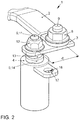
- FIG. 2 shows a perspective view of the arrangement 1, in which an insulated busbar 2 is screwed by means of a nut 8 and a threaded bolt 9 to a lever member 3.
- Die Federelement 2 ist in dem Gezzause 1 für undertake Feder 6 beprofit.
- the busbar 2 is not insulated in order to ensure transmission of electrical traction energy.
- the lever member 3 is oriented substantially perpendicular to the longitudinal extent of the busbar 2 and has at its other end a bore through which the bolt 11 of a torsion bar 5 projects and is screwed by a nut 12 rotatably.
- the mechanically effective length d of the lever element 3 overcomes an offset of the busbar 2 with respect to an axis of the torsion bar 5, which has a flange 13 below the threaded bolt 11, against which the nut 12 presses the lever element 3.
- the flange 13 rests on a flange 14 of a bushing 6, preferably made of plastic, in particular nylon, which guides the torsion bar 5 in a metallic sleeve 4.
- the bushing 6 provides a reduced frictional force between the torsion bar 5 and the sleeve 4.
- the bush 6 also serves to prevent welding at high currents between the torsion bar 5 and the sleeve 4.
- the sleeve 4 can be used as part of an electrochemical energy store be understood and provides a metallic surface for electrical connection of the cells of the electrochemical energy storage to the torsion bar 5 ready.
- the sleeve 4 has a substantially parallel, parallel or with an angle of less than 10 °, oriented to the busbar, for example.
- Laschenförmig formed structure 17 for mechanical connection in which a parallel to the longitudinal extent of the torsion bar oriented bore 18th allows a connection with the electrochemical energy storage.
- the structure 17 is arranged to stabilize the connection to the socket 6 equipped with the first end of the sleeve 4.
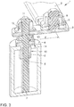
- FIG. 3 shows a sectional view of the in FIG. 2 shown arrangement 1, from which the geometry of the screw of the lever member 3 and the mounting of the torsion bar 5 within the sleeve 4 can be seen.
- a shaft 15 of the sleeve 6 has at the narrowest point between the sleeve 4 and the torsion bar 5, a taper of its outer diameter, whereby it is secured after insertion of the torsion bar 5 against displacement in the axial direction.
Landscapes
- Engineering & Computer Science (AREA)
- Chemical & Material Sciences (AREA)
- General Chemical & Material Sciences (AREA)
- Electrochemistry (AREA)
- Chemical Kinetics & Catalysis (AREA)
- Mechanical Engineering (AREA)
- Transportation (AREA)
- Life Sciences & Earth Sciences (AREA)
- Power Engineering (AREA)
- Sustainable Energy (AREA)
- Sustainable Development (AREA)
- Aviation & Aerospace Engineering (AREA)
- Combustion & Propulsion (AREA)
- Connection Of Batteries Or Terminals (AREA)
- Current-Collector Devices For Electrically Propelled Vehicles (AREA)
Description
Die Elektrifizierung des Personenindividualverkehrs schreitet derzeit rasch voran. Einer der intensiv verfolgten Ansätze besteht darin, elektrische Energie in Form elektrochemischer Zellen in den Fahrzeugen vorzuhalten. Die hohen Massen der elektrochemischen Zellen bedingen insbesondere dann hohe Kräfte an den elektrischen Polen der Zellen, wenn diese über steife Stromschienen an das Bordnetz oder an weiteren Zellen des Fortbewegungsmittels angekoppelt sind, Vibrationen und andere Kräfte können die Zellen daher erheblich beschädigen. Im Stand der Technik werden Stromschienenabschnitte mit vergleichsweise geringen Flächenträgheitsmomenten und zueinander winklig verlaufenden Leitungsabschnitten vorgeschlagen.The electrification of passenger transport is currently progressing rapidly. One of the intensively pursued approaches is to provide electrical energy in the form of electrochemical cells in the vehicles. The high masses of the electrochemical cells require particularly high forces at the electrical poles of the cells when they are coupled via rigid busbars to the electrical system or to other cells of the means of transport, vibrations and other forces can therefore damage the cells considerably. In the prior art busbar sections are proposed with comparatively small area moments of inertia and each other at an angle extending line sections.
Überdies sind im Stand der Technik Drahtgeflechte zur mechanisch flexiblen Führung hoher Ströme bekannt, deren einzelne Litzen jedoch in vergleichsweise hoher Zahl aus dem Gesamtverbund herausbrechen und in Verbindung mit elektrochemischen Energiezellen gefährliche Kurzschlüsse zwischen ungleichnamigen Polen oder an Steuergeräten hervorrufen können.Moreover, wire meshes for mechanically flexible guidance of high currents are known in the prior art, but their individual strands break out of the overall composite in comparatively high numbers and, in conjunction with electrochemical energy cells, can cause dangerous short circuits between unlike poles or control units.
Es ist daher eine Aufgabe der vorliegenden Erfindung, eine platzsparende und mit einem geringen elektrischen Widerstand behaftete Anbindung zwischen einer elektrochemischen Speicherzelle und einem Bordnetz eines Fortbewegungsmittels zu ermöglichen, welche Relativbewegungen ohne Gefahr für die Speicherzelle zulässt.It is therefore an object of the present invention, a space-saving and with a low electrical resistance afflicted connection between an electrochemical storage cell and a vehicle electrical system of a means of transport to allow which relative movements without danger to the memory cell allows.
Die vorstehend identifizierte Aufgabe wird erfindungsgemäß durch eine Anordnung zur Anbindung eines elektrochemischen Energiespeichers an ein Bordnetz eines elektrisch antreibbaren Fortbewegungsmittels gelöst. Der elektrochemische Energiespeicher kann bspw. eine Brennstoffzelle oder eine Traktionsbatterie (auch "Akkumulator") sein. Die Anbindung umfasst eine Stromschiene zur Leitung elektrischer Traktionsenergie in das Bordnetz, welche bspw. integraler Bestandteil des Fortbewegungsmittels sein kann. Eine solche Stromschiene wird mitunter auch als "Hochvolt (HV)-Verbinder" bezeichnet und ist durch vergleichsweise hohe Leiterquerschnitte mit geringem elektrischem Widerstand gekennzeichnet. Die Stromschiene weist eine Längserstreckung auf, welche um ein Vielfaches größer als eine ihrer Quererstreckungen ist. Auf diese Weise kann eine besonders platzsparende, direkte und mit geringstmöglichem elektrischem Widerstand behaftete Übertragung elektrischer Energie von dem elektrochemischen Energiespeicher an einen Traktionsantrieb des Fortbewegungsmittels oder innerhalb der Batterie erfolgen. Erfindungsgemäß ist ein Torsionsstab vorgesehen, welcher eine Längserstreckung aufweist, welche in Richtung des Vektors solcher Torsionsmomente orientiert ist, für welche der Torsionsstab vorgesehen und ausgelegt ist. Die Stromschiene, der Torsionsstab und das Hebelelement sind zum Transport der elektrischen Energie des Energiespeichers elektrisch leitfähig ausgestaltet und elektrisch leitfähig in Reihe miteinander verbunden. Um eine gewisse Toleranz für Relativbewegungen zwischen dem elektrochemischen Energiespeicher und dem Fortbewegungsmittel zu erzeugen, ist die Längserstreckung der Stromschiene im Wesentlichen senkrecht, mit einem Winkel zwischen 80° und 100°, zu der Längserstreckung des Torsionsstabes orientiert. Beispielsweise kann ein im Wesentlichen rechter Winkel zwischen den vorgenannten Längserstreckungen liegen. Das Hebelelement vermittelt einen Versatz, welcher zwischen der Längserstreckung der Stromschiene und der Längserstreckung des Torsionsstabes besteht. Bewegt sich nun die Stromschiene in ihrer Längsrichtung, lenkt sie das Hebelelement aus, welches den Torsionsstab der erfindungsgemäßen Anordnung tordiert. Der Torsionsstab kann über seine Länge die Relativbewegung zwischen der Stromschiene und dem elektrochemischen Energiespeicher ausgleichen. Der Torsionsstab kann bspw.The above-identified object is achieved by an arrangement for connecting an electrochemical energy storage device to an electrical system of an electrically driven means of transport. The electrochemical energy store may, for example, be a fuel cell or a traction battery (also called an "accumulator"). The connection comprises a busbar for conducting electrical traction energy in the electrical system, which, for example, may be an integral part of the means of locomotion. Such a busbar is sometimes referred to as "high-voltage (HV) connector" and is characterized by comparatively high conductor cross-sections with low electrical resistance. The busbar has a longitudinal extent which is many times larger than one of its transverse extensions. In this way, a particularly space-saving, direct and with the least possible electrical resistance transfer of electrical energy from the electrochemical energy storage to a traction drive of the means of transport or within the battery. According to the invention, a torsion bar is provided which has a longitudinal extent which is oriented in the direction of the vector of such torsional moments for which the torsion bar is provided and designed. The busbar, the torsion bar and the lever element are designed to carry the electrical energy of the energy storage electrically conductive and electrically connected in series. In order to generate a certain tolerance for relative movements between the electrochemical energy store and the means of locomotion, the longitudinal extension of the busbar is oriented substantially perpendicular, with an angle between 80 ° and 100 °, to the longitudinal extent of the torsion bar. For example, a substantially right angle between the aforementioned longitudinal extents. The lever element provides an offset, which exists between the longitudinal extent of the busbar and the longitudinal extent of the torsion bar. Now moves the busbar in its longitudinal direction, it deflects the lever element, which twists the torsion bar of the inventive arrangement. The torsion bar can compensate over its length, the relative movement between the busbar and the electrochemical energy storage. The torsion bar can, for example.
Bestandteil des elektrochemischen Energiespeichers sein und bevorzugt anteilig innerhalb eines Gehäuses des elektrochemischen Energiespeichers angeordnet sein. Auf diese Weise kann auf raumgreifende Anordnungen, wie sie der Stand der Technik für eine Vermittlung von Relativbewegungen zwischen dem Fortbewegungsmittel und dem Energiespeicher zur Anordnung außerhalb des Energiespeichers vorschlägt, verzichtet werden.Be part of the electrochemical energy storage and preferably be arranged proportionately within a housing of the electrochemical energy storage. In this way, it is possible to dispense with large-area arrangements, as proposed by the prior art for the mediation of relative movements between the means of transportation and the energy store for the arrangement outside the energy store.
Die Unteransprüche zeigen bevorzugte Weiterbildungen der Erfindung.The dependent claims show preferred developments of the invention.
Die Anordnung kann bevorzugt eine Hülse aufweisen, welche zur Führung einer Verdrehung des Torsionsstabes vorgesehen ist. Die Hülse kann hierzu den Torsionsstab in einem zum Hebelelement benachbarten Abschnitt umschließen und dessen Position an dieser Stelle definieren, während sie eine Rotation des Torsionsstabes an dieser Position zulässt. Wenn sich die Hülse von dieser Position in Richtung eines dem Hebelelement gegenüberliegenden Endes des Torsionsstabes erstreckt, kann die Hülse den Torsionsstab annähernd über seine gesamte Länge umschließen, führen und am dem Hebelelement gegenüberliegenden Ende drehfest fixieren. An diesem Ende kann bspw. eine Fügeverbindung (z. B. eine Reibschweißverbindung) vorgesehen sein, über welche die Momente des Torsionsstabes in die Hülse und ihre Umgebung eingeleitet werden können.The arrangement may preferably have a sleeve which is provided for guiding a rotation of the torsion bar. For this purpose, the sleeve can enclose the torsion bar in a section adjacent to the lever element and define its position at this location while allowing rotation of the torsion bar at this position. When the sleeve extends from this position in the direction of an end of the torsion bar opposite the lever element, the sleeve can surround the torsion bar approximately over its entire length, guide it and fix it in a rotationally fixed manner on the end opposite the lever element. For example, a joining connection (eg a friction-welded connection) can be provided at this end, via which the moments of the torsion bar can be introduced into the sleeve and its surroundings.
Um eine Reibung bei der Führung des Torsionsstabes durch die Hülse zu verringern, kann eine Buchse zwischen der Hülse und dem Torsionsstab angeordnet sein, welche bspw. aus einem Reibkräfte minimierenden, elektrisch isolierenden Material (Kunststoff, insbesondere Nylon) gefertigt sein kann. Auf diese Weise wird eine Kontaktstelle zwischen dem Torsionsstab und der Hülse in diesem Bereich vermieden, welche im Betrieb bei hohen Strömen zu Erwärmung und schlimmstenfalls zum Ausfall der Funktion der Anordnung führen könnte.In order to reduce friction in the leadership of the torsion bar through the sleeve, a bush between the sleeve and the torsion bar can be arranged, which, for example, from a friction minimizing, electrically insulating material (plastic, especially nylon) can be made. In this way, a contact point between the torsion bar and the sleeve is avoided in this area, which could result in operation at high currents to heat and at worst to the failure of the function of the arrangement.
An dem Hebelelement gegenüberliegenden Ende des Torsionsstabes ("erstes distales Ende") können die Hülse und der Torsionsstab elektrisch leitfähig miteinander verbunden sein. Auf diese Weise kann die Hülse zur großflächigen Übertragung elektrischer Energie in den elektrochemischen Energiespeicher verwendet werden, wodurch sich die Übergangswiderstände verringern und der Wirkungsgrad der Anordnung verbessert wird.On the lever element opposite end of the torsion bar ("first distal end"), the sleeve and the torsion bar can be electrically conductively connected to each other. In this way, the sleeve for large-scale transmission of electrical energy can be used in the electrochemical energy storage, whereby the contact resistance is reduced and the efficiency of the arrangement is improved.
Die Hülse kann eine Struktur zur Verankerung in dem elektrochemischen Energiespeicher aufweisen. Die Struktur kann insbesondere eine Übertragung der in die Hülse eingeleiteten Torsionsmomente begünstigen und daher selbst einen mechanischen Hebel zwischen der Hülse und dem elektrochemischen Energiespeicher darstellen. Insbesondere kann die Struktur nach Art einer Lasche ausgestaltet sein. Die Struktur kann eine parallel zur Längserstreckung des Torsionsstabes orientierte Bohrung aufweisen. Die Bohrung kann zur drehfesten Positionierung der Hülse innerhalb des elektrochemischen Energiespeichers verwendet werden. Die Positionierung der Hülse sollte in einem isolierten Bauteil erfolgen, bzw. die Oberfläche der Hülse muss mit isolierendem Material geschützt sein, da die Hülse an der Stromleitung beteiligt ist.The sleeve may have a structure for anchoring in the electrochemical energy store. In particular, the structure may favor a transmission of the torsional moments introduced into the sleeve and therefore itself represent a mechanical lever between the sleeve and the electrochemical energy store. In particular, the structure may be designed in the manner of a tab. The structure may have a bore oriented parallel to the longitudinal extent of the torsion bar. The bore can be used for rotationally fixed positioning of the sleeve within the electrochemical energy store. The positioning of the sleeve should be done in an insulated component, or the surface of the sleeve must be protected with insulating material, since the sleeve is involved in the power line.
Bevorzugt kann der Torsionsstab an seinem dem Hebelelement zugewandten Ende ("zweites distales Ende") ein Gewinde zur Verschraubung des Hebelelementes aufweisen. Dies erleichtert insbesondere den Herstellprozess beim Reibschweißen des Torsionstabes in die Hülse. Proximal kann das Gewinde mit einem Flansch abgeschlossen sein, gegen welchen das Hebelelement mittels der Verschraubung gepresst wird. Hierdurch ergibt sich eine besonders drehfeste Verbindung zwischen dem Hebelelement und dem Torsionsstab, welche durch formschlüssige, korrespondierende Strukturen in dem Hebelelement und dem Torsionsstab weiter begünstigt werden kann.Preferably, the torsion bar at its end facing the lever element ("second distal end") have a thread for screwing the lever element. This facilitates in particular the manufacturing process during friction welding of the torsion bar in the sleeve. Proximal the thread can be completed with a flange against which the lever element is pressed by means of the screw. This results in a particularly rotationally fixed connection between the lever element and the torsion bar, which can be further promoted by positive, corresponding structures in the lever element and the torsion bar.
Entsprechend kann das Hebelelement einen Gewindebolzen aufweisen, welcher zur Verschraubung mit der Stromschiene dient. Der Gewindebolzen kann bspw. an das Hebelelement angeschweißt sein, sodass die Stromschiene durch die Verschraubung auf das Hebelelement gepresst wird. Um die in Längserstreckungsrichtung der Stromschiene übertragenen Wechselkräfte möglichst vollständig in Verdrehungen des Torsionsstabes umzuwandeln, kann die Verbindung zwischen dem Hebelelement und der Stromschiene verdrehbar ausgestaltet sein. Insbesondere können Wälzlager, insbesondere Axiallager, die Verdrehung des Hebelelements gegenüber der Stromschiene unterstützen. Eine Übertragung der elektrischen Energie kann durch Aufbringung von die Leitfähigkeit begünstigenden Oberflächen und fluiden Hilfsmitteln sichergestellt werden.Accordingly, the lever element may have a threaded bolt, which serves for screwing to the busbar. The threaded bolt can, for example, be welded to the lever element, so that the busbar is pressed by the screwing onto the lever element. In order to convert the alternating forces transmitted in the longitudinal extension direction of the busbar as completely as possible into torsions of the torsion bar, the connection between the lever element and the busbar can be made rotatable. In particular, roller bearings, in particular thrust bearings, support the rotation of the lever element relative to the busbar. Transmission of electrical energy can be ensured by application of conductivity-promoting surfaces and fluid aids.
Gemäß einem zweiten Aspekt der vorliegenden Erfindung wird ein Fortbewegungsmittel vorgeschlagen, welches insbesondere als Pkw, als Transporter, als Lkw, als Motorrad, als Luft- und/oder Wasserfahrzeug ausgestaltet sein kann. Das Fortbewegungsmittel weist eine elektrische Maschine auf, welche insbesondere als Traktionsantrieb ausgestaltet sein kann. Eine erfindungsgemäße Anordnung gemäß dem erstgenannten Erfindungsaspekt stellt eine elektrische und mechanische Anbindung des Fortbewegungsmittels an einen internen elektrochemischen Energiespeicher sicher und vermeidet Beschädigungen an der Stromschiene sowie am elektrochemischen Energiespeicher. Die Merkmale, Merkmalskombinationen und die sich aus diesen ergebenden Vorteile entsprechen den in Verbindung mit dem erstgenannten Erfindungsaspekt ausgeführten derart ersichtlich, dass zur Vermeidung von Wiederholungen auf die obigen Ausführungen verwiesen wird.According to a second aspect of the present invention, a means of transportation is proposed, which is designed in particular as a car, as a transporter, as a truck, as a motorcycle, as an aircraft and / or watercraft can be. The means of locomotion comprises an electric machine, which may be configured in particular as a traction drive. An inventive arrangement according to the first-mentioned aspect of the invention ensures an electrical and mechanical connection of the means of locomotion to an internal electrochemical energy storage and avoids damage to the busbar and the electrochemical energy storage. The features, combinations of features and the advantages resulting therefrom correspond to those embodied in connection with the first aspect of the invention so clearly that reference is made to the above statements to avoid repetition.
Nachfolgend werden Ausführungsbeispiele der Erfindung unter Bezugnahme auf die begleitenden Zeichnungen im Detail beschrieben. In den Zeichnungen ist:
Figur 1- eine schematische Übersicht eines Ausführungsbeispiels in einer erfindungsgemäßen Anordnung;
Figur 2- eine perspektivische Ansicht des Ausführungsbeispiels einer erfindungsgemäßen Anordnung; und
Figur 3- eine geschnittene Darstellung des in
Figur 2
- FIG. 1
- a schematic overview of an embodiment in an inventive arrangement;
- FIG. 2
- a perspective view of the embodiment of an inventive arrangement; and
- FIG. 3
- a sectional view of the in
FIG. 2 presented embodiment of the inventive arrangement.
Auch wenn die erfindungsgemäßen Aspekte und vorteilhaften Ausführungsformen anhand der in Verbindung mit den beigefügten Zeichnungsfiguren erläuterten Ausführungsbeispiele im Detail beschrieben worden sind, sind für den Fachmann Modifikationen und Kombinationen von Merkmalen der dargestellten Ausführungsbeispiele möglich, ohne den Bereich der vorliegenden Erfindung zu verlassen, deren Schutzbereich durch die beigefügten Ansprüche definiert wird.Although the aspects and advantageous embodiments of the invention have been described in detail with reference to the embodiments explained in connection with the accompanying drawings, modifications and combinations of features of the illustrated embodiments are possible for the skilled person, without departing from the scope of the present invention, the scope of protection the appended claims are defined.
- 11
- Anordnungarrangement
- 22
- Stromschieneconductor rail
- 33
- Hebelelementlever member
- 44
- Hülseshell
- 55
- Torsionsstabtorsion bar
- 66
- BuchseRifle
- 77
- zweites Ende des Torsionsstabessecond end of the torsion bar
- 88th
- Muttermother
- 99
- Gewindebolzenthreaded bolt
- 1010
- elektrisch antreibbarer Pkwelectrically driven car
- 1111
- Gewindebolzenthreaded bolt
- 1212
- Muttermother
- 1313
- Flanschflange
- 1414
- Flanschflange
- 1515
- Schaftshaft
- 1717
- Strukturstructure
- 1818
- Bohrungdrilling
- 2020
- elektrochemischer Energiespeicher, Traktionsbatterieelectrochemical energy storage, traction battery
- 21, 2221, 22
- Polpole
- 23, 2423, 24
- Stromschieneconductor rail
- 2525
- Masseverbindungground connection
- 2626
- elektrische Traktionsmaschineelectric traction machine
- dd
- Versatz zwischen Stromschiene und TorsionsstabOffset between busbar and torsion bar
Claims (10)
- Arrangement for connecting an electrochemical energy store (20) to an on-board power supply of an electrically driveable means of locomotion (10), comprising:- a busbar (2; 23, 24) for conducting electrical traction energy into the on-board power supply,- a torsion bar (5), and- a lever element (3), whereinthe busbar (2; 23, 24), the torsion bar (5) and the lever element (3) are configured in an electrically conductive fashion,
the busbar (2; 23, 24) and the torsion bar (5) are connected to one another in an electrically conductive fashion via the lever element (3),
wherein a longitudinal extent of the busbar (2; 23, 24) is oriented essentially perpendicularly with respect to a longitudinal extent of the torsion bar (5), and the lever element (3) has an offset (d) between the longitudinal extent of the busbar (2; 23, 24) and the longitudinal extent of the torsion bar (5). - Arrangement according to Claim 1, further comprising a sleeve (4) for guiding torsion of the torsion bar (5).
- Arrangement according to Claim 1 or 2, further comprising a socket (6) between the sleeve (4) and the torsion bar (5).
- Arrangement according to one of the preceding claims, wherein the sleeve (4) and the torsion bar (5) are connected to one another at a common first distal end (7) in an electrically conductive and mechanically rotationally fixed fashion.
- Arrangement according to one of the preceding claims, wherein the sleeve (4) has a structure (17) for anchoring in the electrochemical energy store (20) .
- Arrangement according to Claim 5, wherein the structure (17) has a clip with a drill hole (18) which is oriented parallel to the longitudinal extent of the torsion bar.
- Arrangement according to one of the preceding claims, wherein the torsion bar (5) has, at a second distal end (11), a thread for screwing the lever element (3).
- Arrangement according to one of the preceding claims, wherein the lever element (3) has a threaded bolt (9) for screwing the busbar (2; 23, 24).
- Arrangement according to one of the preceding claims, wherein the lever element (3) is rotatably fastened to the busbar (2; 23, 24).
- Means of locomotion, in particular a road vehicle which can have an electric drive, comprising an arrangement according to one of the preceding claims.
Applications Claiming Priority (2)
| Application Number | Priority Date | Filing Date | Title |
|---|---|---|---|
| DE102015204724.5A DE102015204724A1 (en) | 2015-03-16 | 2015-03-16 | Means of transport and arrangement for connecting an electrochemical energy store to a vehicle electrical system of an electrically driven means of transportation |
| PCT/EP2015/076574 WO2016146212A1 (en) | 2015-03-16 | 2015-11-13 | Transportation means and arrangement for linking an electrochemical energy store to an onboard power supply of an electrically drivable transportation means |
Publications (2)
| Publication Number | Publication Date |
|---|---|
| EP3271955A1 EP3271955A1 (en) | 2018-01-24 |
| EP3271955B1 true EP3271955B1 (en) | 2019-01-09 |
Family
ID=54541084
Family Applications (1)
| Application Number | Title | Priority Date | Filing Date |
|---|---|---|---|
| EP15794194.9A Active EP3271955B1 (en) | 2015-03-16 | 2015-11-13 | Transportation means and arrangement for linking an electrochemical energy store to an onboard power supply of an electrically drivable transportation means |
Country Status (4)
| Country | Link |
|---|---|
| EP (1) | EP3271955B1 (en) |
| CN (1) | CN107428235B (en) |
| DE (1) | DE102015204724A1 (en) |
| WO (1) | WO2016146212A1 (en) |
Family Cites Families (10)
| Publication number | Priority date | Publication date | Assignee | Title |
|---|---|---|---|---|
| KR100264607B1 (en) * | 1997-12-09 | 2000-09-01 | 정몽규 | Battery mounting structure of electric vehicle |
| US6161810A (en) * | 1999-02-16 | 2000-12-19 | Delphi Technologies, Inc. | Torsion rod holddown apparatus for a battery |
| DE202011000930U1 (en) * | 2011-04-19 | 2014-01-22 | Hagemann-Systems Gmbh | battery connector |
| JP2013020855A (en) | 2011-07-12 | 2013-01-31 | Sanyo Electric Co Ltd | Power supply unit and vehicle including power supply unit |
| KR101361113B1 (en) * | 2011-07-13 | 2014-02-13 | 주식회사 엘지화학 | Battery Module of Improved Connection Reliability and Battery Pack Employed with the Same |
| DE102012217368A1 (en) * | 2012-09-26 | 2014-03-27 | Robert Bosch Gmbh | Connection element in omega form for the electrical connection of battery cells of a battery module |
| KR101428331B1 (en) * | 2012-12-27 | 2014-08-07 | 현대자동차주식회사 | Safety apparatus of battery module for vehicle |
| DE102013004349A1 (en) | 2013-03-12 | 2014-09-18 | Volkswagen Aktiengesellschaft | Device for electrical connection |
| CN103606637B (en) * | 2013-11-30 | 2016-05-04 | 东莞市金源电池科技有限公司 | A kind of electric vehicle lithium battery |
| CN103730626A (en) * | 2014-01-24 | 2014-04-16 | 安徽江淮汽车股份有限公司 | Storage battery electrode connecting structure and storage battery electrode connection method |
-
2015
- 2015-03-16 DE DE102015204724.5A patent/DE102015204724A1/en not_active Withdrawn
- 2015-11-13 CN CN201580077816.7A patent/CN107428235B/en active Active
- 2015-11-13 EP EP15794194.9A patent/EP3271955B1/en active Active
- 2015-11-13 WO PCT/EP2015/076574 patent/WO2016146212A1/en active Application Filing
Non-Patent Citations (1)
| Title |
|---|
| None * |
Also Published As
| Publication number | Publication date |
|---|---|
| CN107428235A (en) | 2017-12-01 |
| CN107428235B (en) | 2019-09-03 |
| DE102015204724A1 (en) | 2016-09-22 |
| WO2016146212A1 (en) | 2016-09-22 |
| EP3271955A1 (en) | 2018-01-24 |
Similar Documents
| Publication | Publication Date | Title |
|---|---|---|
| DE102016117261B3 (en) | System consisting of a connector, a fluid-cooled cable and a connection unit | |
| EP2828932B1 (en) | Electrical connection secured against rotation, in particular for an electrically heatable honeycomb body | |
| EP3300223B1 (en) | Releasable connector assembly for high currents | |
| EP2572396B1 (en) | Lithium-ion battery cell and method for producing an electrically conductive contact with terminals of battery cells | |
| DE102010038407B4 (en) | Aerial or spacecraft with an electrical distribution arrangement | |
| DE102007057501A1 (en) | Electrical contact device for controller of motor vehicle, has bus bar for supplying electrical energy to controller from cable or pole terminal, and press-fit connection placed in electrical contact with bus bar | |
| EP3271955B1 (en) | Transportation means and arrangement for linking an electrochemical energy store to an onboard power supply of an electrically drivable transportation means | |
| DE102018203578B4 (en) | Arrangement for the electrical connection of pole terminals and cell module or battery with such a connection arrangement (I) | |
| EP2485331A2 (en) | Battery clamp | |
| DE102015204261A1 (en) | Axle carrier for a vehicle | |
| EP3194238B1 (en) | Car connection system for guiding at least one supply cable | |
| WO2012052184A1 (en) | Plug part of a plug-type apparatus | |
| DE102012202694A1 (en) | Housing for module of traction battery for e.g. passenger car, has electrochemical cells including electrodes, and fixing elements arranged adjacent to each opening for fastening bus bar, where openings are provided adjacent to electrodes | |
| DE102016013799A1 (en) | A fuel cell assembly | |
| DE102015218747A1 (en) | HV cable connector assembly | |
| WO2011086086A1 (en) | Battery, battery system and method for connecting a plurality of batteries | |
| DE102018211171A1 (en) | Battery device for a motor vehicle and motor vehicle with a battery device | |
| DE10323613B4 (en) | Plug or socket of a plug connection or connector in Schnellanschlusstecnik | |
| DE102014017869A1 (en) | Plug device for electrically connecting two battery units of a motor vehicle | |
| DE102018218163A1 (en) | Interface module, inverter and vehicle | |
| EP4080666B1 (en) | Battery module connector, method for producing a battery module connector and battery system | |
| DE102020129438A1 (en) | Energy storage and motor vehicle | |
| EP2637234B1 (en) | Battery structure for a motor vehicle | |
| WO2024037805A1 (en) | Connecting device for battery cells of a traction battery, and traction battery | |
| DE10220303A1 (en) | Voltage supply arrangement for electrical devices in a motor vehicle has a supply platform joined to the vehicle body and short cables |
Legal Events
| Date | Code | Title | Description |
|---|---|---|---|
| STAA | Information on the status of an ep patent application or granted ep patent |
Free format text: STATUS: THE INTERNATIONAL PUBLICATION HAS BEEN MADE |
|
| PUAI | Public reference made under article 153(3) epc to a published international application that has entered the european phase |
Free format text: ORIGINAL CODE: 0009012 |
|
| STAA | Information on the status of an ep patent application or granted ep patent |
Free format text: STATUS: REQUEST FOR EXAMINATION WAS MADE |
|
| 17P | Request for examination filed |
Effective date: 20171016 |
|
| AK | Designated contracting states |
Kind code of ref document: A1 Designated state(s): AL AT BE BG CH CY CZ DE DK EE ES FI FR GB GR HR HU IE IS IT LI LT LU LV MC MK MT NL NO PL PT RO RS SE SI SK SM TR |
|
| AX | Request for extension of the european patent |
Extension state: BA ME |
|
| DAV | Request for validation of the european patent (deleted) | ||
| DAX | Request for extension of the european patent (deleted) | ||
| GRAP | Despatch of communication of intention to grant a patent |
Free format text: ORIGINAL CODE: EPIDOSNIGR1 |
|
| STAA | Information on the status of an ep patent application or granted ep patent |
Free format text: STATUS: GRANT OF PATENT IS INTENDED |
|
| INTG | Intention to grant announced |
Effective date: 20180709 |
|
| GRAS | Grant fee paid |
Free format text: ORIGINAL CODE: EPIDOSNIGR3 |
|
| GRAA | (expected) grant |
Free format text: ORIGINAL CODE: 0009210 |
|
| STAA | Information on the status of an ep patent application or granted ep patent |
Free format text: STATUS: THE PATENT HAS BEEN GRANTED |
|
| AK | Designated contracting states |
Kind code of ref document: B1 Designated state(s): AL AT BE BG CH CY CZ DE DK EE ES FI FR GB GR HR HU IE IS IT LI LT LU LV MC MK MT NL NO PL PT RO RS SE SI SK SM TR |
|
| REG | Reference to a national code |
Ref country code: GB Ref legal event code: FG4D Free format text: NOT ENGLISH |
|
| REG | Reference to a national code |
Ref country code: CH Ref legal event code: EP Ref country code: AT Ref legal event code: REF Ref document number: 1088432 Country of ref document: AT Kind code of ref document: T Effective date: 20190115 |
|
| REG | Reference to a national code |
Ref country code: DE Ref legal event code: R096 Ref document number: 502015007648 Country of ref document: DE |
|
| REG | Reference to a national code |
Ref country code: IE Ref legal event code: FG4D Free format text: LANGUAGE OF EP DOCUMENT: GERMAN |
|
| REG | Reference to a national code |
Ref country code: NL Ref legal event code: MP Effective date: 20190109 |
|
| REG | Reference to a national code |
Ref country code: LT Ref legal event code: MG4D |
|
| PG25 | Lapsed in a contracting state [announced via postgrant information from national office to epo] |
Ref country code: NL Free format text: LAPSE BECAUSE OF FAILURE TO SUBMIT A TRANSLATION OF THE DESCRIPTION OR TO PAY THE FEE WITHIN THE PRESCRIBED TIME-LIMIT Effective date: 20190109 |
|
| PG25 | Lapsed in a contracting state [announced via postgrant information from national office to epo] |
Ref country code: PT Free format text: LAPSE BECAUSE OF FAILURE TO SUBMIT A TRANSLATION OF THE DESCRIPTION OR TO PAY THE FEE WITHIN THE PRESCRIBED TIME-LIMIT Effective date: 20190509 Ref country code: ES Free format text: LAPSE BECAUSE OF FAILURE TO SUBMIT A TRANSLATION OF THE DESCRIPTION OR TO PAY THE FEE WITHIN THE PRESCRIBED TIME-LIMIT Effective date: 20190109 Ref country code: PL Free format text: LAPSE BECAUSE OF FAILURE TO SUBMIT A TRANSLATION OF THE DESCRIPTION OR TO PAY THE FEE WITHIN THE PRESCRIBED TIME-LIMIT Effective date: 20190109 Ref country code: LT Free format text: LAPSE BECAUSE OF FAILURE TO SUBMIT A TRANSLATION OF THE DESCRIPTION OR TO PAY THE FEE WITHIN THE PRESCRIBED TIME-LIMIT Effective date: 20190109 Ref country code: SE Free format text: LAPSE BECAUSE OF FAILURE TO SUBMIT A TRANSLATION OF THE DESCRIPTION OR TO PAY THE FEE WITHIN THE PRESCRIBED TIME-LIMIT Effective date: 20190109 Ref country code: NO Free format text: LAPSE BECAUSE OF FAILURE TO SUBMIT A TRANSLATION OF THE DESCRIPTION OR TO PAY THE FEE WITHIN THE PRESCRIBED TIME-LIMIT Effective date: 20190409 Ref country code: FI Free format text: LAPSE BECAUSE OF FAILURE TO SUBMIT A TRANSLATION OF THE DESCRIPTION OR TO PAY THE FEE WITHIN THE PRESCRIBED TIME-LIMIT Effective date: 20190109 |
|
| PG25 | Lapsed in a contracting state [announced via postgrant information from national office to epo] |
Ref country code: RS Free format text: LAPSE BECAUSE OF FAILURE TO SUBMIT A TRANSLATION OF THE DESCRIPTION OR TO PAY THE FEE WITHIN THE PRESCRIBED TIME-LIMIT Effective date: 20190109 Ref country code: BG Free format text: LAPSE BECAUSE OF FAILURE TO SUBMIT A TRANSLATION OF THE DESCRIPTION OR TO PAY THE FEE WITHIN THE PRESCRIBED TIME-LIMIT Effective date: 20190409 Ref country code: GR Free format text: LAPSE BECAUSE OF FAILURE TO SUBMIT A TRANSLATION OF THE DESCRIPTION OR TO PAY THE FEE WITHIN THE PRESCRIBED TIME-LIMIT Effective date: 20190410 Ref country code: IS Free format text: LAPSE BECAUSE OF FAILURE TO SUBMIT A TRANSLATION OF THE DESCRIPTION OR TO PAY THE FEE WITHIN THE PRESCRIBED TIME-LIMIT Effective date: 20190509 Ref country code: LV Free format text: LAPSE BECAUSE OF FAILURE TO SUBMIT A TRANSLATION OF THE DESCRIPTION OR TO PAY THE FEE WITHIN THE PRESCRIBED TIME-LIMIT Effective date: 20190109 Ref country code: HR Free format text: LAPSE BECAUSE OF FAILURE TO SUBMIT A TRANSLATION OF THE DESCRIPTION OR TO PAY THE FEE WITHIN THE PRESCRIBED TIME-LIMIT Effective date: 20190109 |
|
| REG | Reference to a national code |
Ref country code: DE Ref legal event code: R097 Ref document number: 502015007648 Country of ref document: DE |
|
| PG25 | Lapsed in a contracting state [announced via postgrant information from national office to epo] |
Ref country code: IT Free format text: LAPSE BECAUSE OF FAILURE TO SUBMIT A TRANSLATION OF THE DESCRIPTION OR TO PAY THE FEE WITHIN THE PRESCRIBED TIME-LIMIT Effective date: 20190109 Ref country code: AL Free format text: LAPSE BECAUSE OF FAILURE TO SUBMIT A TRANSLATION OF THE DESCRIPTION OR TO PAY THE FEE WITHIN THE PRESCRIBED TIME-LIMIT Effective date: 20190109 Ref country code: SK Free format text: LAPSE BECAUSE OF FAILURE TO SUBMIT A TRANSLATION OF THE DESCRIPTION OR TO PAY THE FEE WITHIN THE PRESCRIBED TIME-LIMIT Effective date: 20190109 Ref country code: DK Free format text: LAPSE BECAUSE OF FAILURE TO SUBMIT A TRANSLATION OF THE DESCRIPTION OR TO PAY THE FEE WITHIN THE PRESCRIBED TIME-LIMIT Effective date: 20190109 Ref country code: CZ Free format text: LAPSE BECAUSE OF FAILURE TO SUBMIT A TRANSLATION OF THE DESCRIPTION OR TO PAY THE FEE WITHIN THE PRESCRIBED TIME-LIMIT Effective date: 20190109 Ref country code: EE Free format text: LAPSE BECAUSE OF FAILURE TO SUBMIT A TRANSLATION OF THE DESCRIPTION OR TO PAY THE FEE WITHIN THE PRESCRIBED TIME-LIMIT Effective date: 20190109 Ref country code: RO Free format text: LAPSE BECAUSE OF FAILURE TO SUBMIT A TRANSLATION OF THE DESCRIPTION OR TO PAY THE FEE WITHIN THE PRESCRIBED TIME-LIMIT Effective date: 20190109 |
|
| PLBE | No opposition filed within time limit |
Free format text: ORIGINAL CODE: 0009261 |
|
| STAA | Information on the status of an ep patent application or granted ep patent |
Free format text: STATUS: NO OPPOSITION FILED WITHIN TIME LIMIT |
|
| PG25 | Lapsed in a contracting state [announced via postgrant information from national office to epo] |
Ref country code: SM Free format text: LAPSE BECAUSE OF FAILURE TO SUBMIT A TRANSLATION OF THE DESCRIPTION OR TO PAY THE FEE WITHIN THE PRESCRIBED TIME-LIMIT Effective date: 20190109 |
|
| 26N | No opposition filed |
Effective date: 20191010 |
|
| PG25 | Lapsed in a contracting state [announced via postgrant information from national office to epo] |
Ref country code: SI Free format text: LAPSE BECAUSE OF FAILURE TO SUBMIT A TRANSLATION OF THE DESCRIPTION OR TO PAY THE FEE WITHIN THE PRESCRIBED TIME-LIMIT Effective date: 20190109 |
|
| PG25 | Lapsed in a contracting state [announced via postgrant information from national office to epo] |
Ref country code: TR Free format text: LAPSE BECAUSE OF FAILURE TO SUBMIT A TRANSLATION OF THE DESCRIPTION OR TO PAY THE FEE WITHIN THE PRESCRIBED TIME-LIMIT Effective date: 20190109 |
|
| REG | Reference to a national code |
Ref country code: CH Ref legal event code: PL |
|
| PG25 | Lapsed in a contracting state [announced via postgrant information from national office to epo] |
Ref country code: MC Free format text: LAPSE BECAUSE OF FAILURE TO SUBMIT A TRANSLATION OF THE DESCRIPTION OR TO PAY THE FEE WITHIN THE PRESCRIBED TIME-LIMIT Effective date: 20190109 Ref country code: CH Free format text: LAPSE BECAUSE OF NON-PAYMENT OF DUE FEES Effective date: 20191130 Ref country code: LU Free format text: LAPSE BECAUSE OF NON-PAYMENT OF DUE FEES Effective date: 20191113 Ref country code: LI Free format text: LAPSE BECAUSE OF NON-PAYMENT OF DUE FEES Effective date: 20191130 |
|
| REG | Reference to a national code |
Ref country code: BE Ref legal event code: MM Effective date: 20191130 |
|
| PG25 | Lapsed in a contracting state [announced via postgrant information from national office to epo] |
Ref country code: IE Free format text: LAPSE BECAUSE OF NON-PAYMENT OF DUE FEES Effective date: 20191113 |
|
| REG | Reference to a national code |
Ref country code: DE Ref legal event code: R079 Ref document number: 502015007648 Country of ref document: DE Free format text: PREVIOUS MAIN CLASS: H01M0002100000 Ipc: H01M0050200000 |
|
| PG25 | Lapsed in a contracting state [announced via postgrant information from national office to epo] |
Ref country code: BE Free format text: LAPSE BECAUSE OF NON-PAYMENT OF DUE FEES Effective date: 20191130 |
|
| PG25 | Lapsed in a contracting state [announced via postgrant information from national office to epo] |
Ref country code: CY Free format text: LAPSE BECAUSE OF FAILURE TO SUBMIT A TRANSLATION OF THE DESCRIPTION OR TO PAY THE FEE WITHIN THE PRESCRIBED TIME-LIMIT Effective date: 20190109 |
|
| PG25 | Lapsed in a contracting state [announced via postgrant information from national office to epo] |
Ref country code: HU Free format text: LAPSE BECAUSE OF FAILURE TO SUBMIT A TRANSLATION OF THE DESCRIPTION OR TO PAY THE FEE WITHIN THE PRESCRIBED TIME-LIMIT; INVALID AB INITIO Effective date: 20151113 Ref country code: MT Free format text: LAPSE BECAUSE OF FAILURE TO SUBMIT A TRANSLATION OF THE DESCRIPTION OR TO PAY THE FEE WITHIN THE PRESCRIBED TIME-LIMIT Effective date: 20190109 |
|
| REG | Reference to a national code |
Ref country code: AT Ref legal event code: MM01 Ref document number: 1088432 Country of ref document: AT Kind code of ref document: T Effective date: 20201113 |
|
| PG25 | Lapsed in a contracting state [announced via postgrant information from national office to epo] |
Ref country code: AT Free format text: LAPSE BECAUSE OF NON-PAYMENT OF DUE FEES Effective date: 20201113 |
|
| PG25 | Lapsed in a contracting state [announced via postgrant information from national office to epo] |
Ref country code: MK Free format text: LAPSE BECAUSE OF FAILURE TO SUBMIT A TRANSLATION OF THE DESCRIPTION OR TO PAY THE FEE WITHIN THE PRESCRIBED TIME-LIMIT Effective date: 20190109 |
|
| P01 | Opt-out of the competence of the unified patent court (upc) registered |
Effective date: 20230523 |
|
| PGFP | Annual fee paid to national office [announced via postgrant information from national office to epo] |
Ref country code: GB Payment date: 20231121 Year of fee payment: 9 |
|
| PGFP | Annual fee paid to national office [announced via postgrant information from national office to epo] |
Ref country code: FR Payment date: 20231123 Year of fee payment: 9 Ref country code: DE Payment date: 20231130 Year of fee payment: 9 |