EP3271581B1 - Motorpumpenaggregat mit einer einzelnen elastischen membran - Google Patents
Motorpumpenaggregat mit einer einzelnen elastischen membran Download PDFInfo
- Publication number
- EP3271581B1 EP3271581B1 EP16709939.9A EP16709939A EP3271581B1 EP 3271581 B1 EP3271581 B1 EP 3271581B1 EP 16709939 A EP16709939 A EP 16709939A EP 3271581 B1 EP3271581 B1 EP 3271581B1
- Authority
- EP
- European Patent Office
- Prior art keywords
- motor
- pump assembly
- working
- unit
- air
- Prior art date
- Legal status (The legal status is an assumption and is not a legal conclusion. Google has not performed a legal analysis and makes no representation as to the accuracy of the status listed.)
- Active
Links
Images



Classifications
-
- F—MECHANICAL ENGINEERING; LIGHTING; HEATING; WEAPONS; BLASTING
- F04—POSITIVE - DISPLACEMENT MACHINES FOR LIQUIDS; PUMPS FOR LIQUIDS OR ELASTIC FLUIDS
- F04B—POSITIVE-DISPLACEMENT MACHINES FOR LIQUIDS; PUMPS
- F04B45/00—Pumps or pumping installations having flexible working members and specially adapted for elastic fluids
- F04B45/04—Pumps or pumping installations having flexible working members and specially adapted for elastic fluids having plate-like flexible members, e.g. diaphragms
- F04B45/047—Pumps having electric drive
-
- B—PERFORMING OPERATIONS; TRANSPORTING
- B60—VEHICLES IN GENERAL
- B60T—VEHICLE BRAKE CONTROL SYSTEMS OR PARTS THEREOF; BRAKE CONTROL SYSTEMS OR PARTS THEREOF, IN GENERAL; ARRANGEMENT OF BRAKING ELEMENTS ON VEHICLES IN GENERAL; PORTABLE DEVICES FOR PREVENTING UNWANTED MOVEMENT OF VEHICLES; VEHICLE MODIFICATIONS TO FACILITATE COOLING OF BRAKES
- B60T13/00—Transmitting braking action from initiating means to ultimate brake actuator with power assistance or drive; Brake systems incorporating such transmitting means, e.g. air-pressure brake systems
- B60T13/10—Transmitting braking action from initiating means to ultimate brake actuator with power assistance or drive; Brake systems incorporating such transmitting means, e.g. air-pressure brake systems with fluid assistance, drive, or release
- B60T13/24—Transmitting braking action from initiating means to ultimate brake actuator with power assistance or drive; Brake systems incorporating such transmitting means, e.g. air-pressure brake systems with fluid assistance, drive, or release the fluid being gaseous
- B60T13/46—Vacuum systems
- B60T13/52—Vacuum systems indirect, i.e. vacuum booster units
- B60T13/569—Vacuum systems indirect, i.e. vacuum booster units characterised by piston details, e.g. construction, mounting of diaphragm
-
- B—PERFORMING OPERATIONS; TRANSPORTING
- B60—VEHICLES IN GENERAL
- B60T—VEHICLE BRAKE CONTROL SYSTEMS OR PARTS THEREOF; BRAKE CONTROL SYSTEMS OR PARTS THEREOF, IN GENERAL; ARRANGEMENT OF BRAKING ELEMENTS ON VEHICLES IN GENERAL; PORTABLE DEVICES FOR PREVENTING UNWANTED MOVEMENT OF VEHICLES; VEHICLE MODIFICATIONS TO FACILITATE COOLING OF BRAKES
- B60T17/00—Component parts, details, or accessories of power brake systems not covered by groups B60T8/00, B60T13/00 or B60T15/00, or presenting other characteristic features
- B60T17/02—Arrangements of pumps or compressors, or control devices therefor
-
- F—MECHANICAL ENGINEERING; LIGHTING; HEATING; WEAPONS; BLASTING
- F04—POSITIVE - DISPLACEMENT MACHINES FOR LIQUIDS; PUMPS FOR LIQUIDS OR ELASTIC FLUIDS
- F04B—POSITIVE-DISPLACEMENT MACHINES FOR LIQUIDS; PUMPS
- F04B11/00—Equalisation of pulses, e.g. by use of air vessels; Counteracting cavitation
-
- F—MECHANICAL ENGINEERING; LIGHTING; HEATING; WEAPONS; BLASTING
- F04—POSITIVE - DISPLACEMENT MACHINES FOR LIQUIDS; PUMPS FOR LIQUIDS OR ELASTIC FLUIDS
- F04B—POSITIVE-DISPLACEMENT MACHINES FOR LIQUIDS; PUMPS
- F04B39/00—Component parts, details, or accessories, of pumps or pumping systems specially adapted for elastic fluids, not otherwise provided for in, or of interest apart from, groups F04B25/00 - F04B37/00
- F04B39/0027—Pulsation and noise damping means
- F04B39/005—Pulsation and noise damping means with direct action on the fluid flow using absorptive materials
-
- F—MECHANICAL ENGINEERING; LIGHTING; HEATING; WEAPONS; BLASTING
- F04—POSITIVE - DISPLACEMENT MACHINES FOR LIQUIDS; PUMPS FOR LIQUIDS OR ELASTIC FLUIDS
- F04B—POSITIVE-DISPLACEMENT MACHINES FOR LIQUIDS; PUMPS
- F04B39/00—Component parts, details, or accessories, of pumps or pumping systems specially adapted for elastic fluids, not otherwise provided for in, or of interest apart from, groups F04B25/00 - F04B37/00
- F04B39/12—Casings; Cylinders; Cylinder heads; Fluid connections
- F04B39/121—Casings
-
- F—MECHANICAL ENGINEERING; LIGHTING; HEATING; WEAPONS; BLASTING
- F04—POSITIVE - DISPLACEMENT MACHINES FOR LIQUIDS; PUMPS FOR LIQUIDS OR ELASTIC FLUIDS
- F04B—POSITIVE-DISPLACEMENT MACHINES FOR LIQUIDS; PUMPS
- F04B39/00—Component parts, details, or accessories, of pumps or pumping systems specially adapted for elastic fluids, not otherwise provided for in, or of interest apart from, groups F04B25/00 - F04B37/00
- F04B39/12—Casings; Cylinders; Cylinder heads; Fluid connections
- F04B39/125—Cylinder heads
-
- F—MECHANICAL ENGINEERING; LIGHTING; HEATING; WEAPONS; BLASTING
- F04—POSITIVE - DISPLACEMENT MACHINES FOR LIQUIDS; PUMPS FOR LIQUIDS OR ELASTIC FLUIDS
- F04B—POSITIVE-DISPLACEMENT MACHINES FOR LIQUIDS; PUMPS
- F04B53/00—Component parts, details or accessories not provided for in, or of interest apart from, groups F04B1/00 - F04B23/00 or F04B39/00 - F04B47/00
- F04B53/001—Noise damping
- F04B53/003—Noise damping by damping supports
-
- F—MECHANICAL ENGINEERING; LIGHTING; HEATING; WEAPONS; BLASTING
- F04—POSITIVE - DISPLACEMENT MACHINES FOR LIQUIDS; PUMPS FOR LIQUIDS OR ELASTIC FLUIDS
- F04B—POSITIVE-DISPLACEMENT MACHINES FOR LIQUIDS; PUMPS
- F04B53/00—Component parts, details or accessories not provided for in, or of interest apart from, groups F04B1/00 - F04B23/00 or F04B39/00 - F04B47/00
- F04B53/10—Valves; Arrangement of valves
-
- F—MECHANICAL ENGINEERING; LIGHTING; HEATING; WEAPONS; BLASTING
- F04—POSITIVE - DISPLACEMENT MACHINES FOR LIQUIDS; PUMPS FOR LIQUIDS OR ELASTIC FLUIDS
- F04B—POSITIVE-DISPLACEMENT MACHINES FOR LIQUIDS; PUMPS
- F04B53/00—Component parts, details or accessories not provided for in, or of interest apart from, groups F04B1/00 - F04B23/00 or F04B39/00 - F04B47/00
- F04B53/10—Valves; Arrangement of valves
- F04B53/1072—Valves; Arrangement of valves the valve being an elastic body, the length thereof changing in the opening direction
-
- F—MECHANICAL ENGINEERING; LIGHTING; HEATING; WEAPONS; BLASTING
- F04—POSITIVE - DISPLACEMENT MACHINES FOR LIQUIDS; PUMPS FOR LIQUIDS OR ELASTIC FLUIDS
- F04B—POSITIVE-DISPLACEMENT MACHINES FOR LIQUIDS; PUMPS
- F04B53/00—Component parts, details or accessories not provided for in, or of interest apart from, groups F04B1/00 - F04B23/00 or F04B39/00 - F04B47/00
- F04B53/16—Casings; Cylinders; Cylinder liners or heads; Fluid connections
-
- F—MECHANICAL ENGINEERING; LIGHTING; HEATING; WEAPONS; BLASTING
- F04—POSITIVE - DISPLACEMENT MACHINES FOR LIQUIDS; PUMPS FOR LIQUIDS OR ELASTIC FLUIDS
- F04B—POSITIVE-DISPLACEMENT MACHINES FOR LIQUIDS; PUMPS
- F04B53/00—Component parts, details or accessories not provided for in, or of interest apart from, groups F04B1/00 - F04B23/00 or F04B39/00 - F04B47/00
- F04B53/20—Filtering
-
- F—MECHANICAL ENGINEERING; LIGHTING; HEATING; WEAPONS; BLASTING
- F04—POSITIVE - DISPLACEMENT MACHINES FOR LIQUIDS; PUMPS FOR LIQUIDS OR ELASTIC FLUIDS
- F04B—POSITIVE-DISPLACEMENT MACHINES FOR LIQUIDS; PUMPS
- F04B35/00—Piston pumps specially adapted for elastic fluids and characterised by the driving means to their working members, or by combination with, or adaptation to, specific driving engines or motors, not otherwise provided for
- F04B35/01—Piston pumps specially adapted for elastic fluids and characterised by the driving means to their working members, or by combination with, or adaptation to, specific driving engines or motors, not otherwise provided for the means being mechanical
-
- F—MECHANICAL ENGINEERING; LIGHTING; HEATING; WEAPONS; BLASTING
- F04—POSITIVE - DISPLACEMENT MACHINES FOR LIQUIDS; PUMPS FOR LIQUIDS OR ELASTIC FLUIDS
- F04B—POSITIVE-DISPLACEMENT MACHINES FOR LIQUIDS; PUMPS
- F04B35/00—Piston pumps specially adapted for elastic fluids and characterised by the driving means to their working members, or by combination with, or adaptation to, specific driving engines or motors, not otherwise provided for
- F04B35/04—Piston pumps specially adapted for elastic fluids and characterised by the driving means to their working members, or by combination with, or adaptation to, specific driving engines or motors, not otherwise provided for the means being electric
-
- F—MECHANICAL ENGINEERING; LIGHTING; HEATING; WEAPONS; BLASTING
- F05—INDEXING SCHEMES RELATING TO ENGINES OR PUMPS IN VARIOUS SUBCLASSES OF CLASSES F01-F04
- F05B—INDEXING SCHEME RELATING TO WIND, SPRING, WEIGHT, INERTIA OR LIKE MOTORS, TO MACHINES OR ENGINES FOR LIQUIDS COVERED BY SUBCLASSES F03B, F03D AND F03G
- F05B2210/00—Working fluid
- F05B2210/10—Kind or type
- F05B2210/12—Kind or type gaseous, i.e. compressible
-
- F—MECHANICAL ENGINEERING; LIGHTING; HEATING; WEAPONS; BLASTING
- F05—INDEXING SCHEMES RELATING TO ENGINES OR PUMPS IN VARIOUS SUBCLASSES OF CLASSES F01-F04
- F05B—INDEXING SCHEME RELATING TO WIND, SPRING, WEIGHT, INERTIA OR LIKE MOTORS, TO MACHINES OR ENGINES FOR LIQUIDS COVERED BY SUBCLASSES F03B, F03D AND F03G
- F05B2280/00—Materials; Properties thereof
- F05B2280/40—Organic materials
- F05B2280/4003—Synthetic polymers, e.g. plastics
Definitions
- the invention relates to a motor pump unit, in particular for supplying a vacuum to a pneumatic brake booster for a hydraulic car brake system.
- Modern vehicle drives usually provide too little or no vacuum at all to be able to operate a pneumatic brake booster. This necessitates the use of separate pump units to generate the necessary vacuum.
- Vane pumps and double-diaphragm pumps with two opposing elastomeric diaphragms in a boxer arrangement such as from WO 2007/134928 A1 known.
- double diaphragm pumps have particular advantages in that they function reliably even at high temperatures and at high altitudes with low air pressure, and also have a steep air flow rate start-up characteristic.
- they are also usually heavier, larger, more complex and therefore more expensive than vane pumps.
- such constructions often require complex devices to protect against water penetration into the interior in order to avoid damage to the motor pump unit and the brake booster.
- the task therefore arises of offering a motor pump unit which is simpler, more compact and less expensive while maintaining the advantages of double diaphragm pumps.
- the construction according to the invention of a highly integrated unit with a single membrane enables the use of a smaller and lighter electric drive, the reduction of individual parts and a considerable reduction in costs, weight and assembly effort. More compact external dimensions allow packaging in the engine compartment of a motor vehicle.
- a pneumatic connection for connecting the working chamber of the motor pump unit to the consumer can be arranged particularly advantageously directly on the working chamber cover in the immediate vicinity of the inlet valve and, in particular, can be formed on it.
- the pneumatic connection can be flexibly adapted depending on the space requirements, both in terms of direction and position, as well as the type - for example as a socket, a bayonet lock, a quick-release fastener or a quick connector.
- a silencer unit with a porous filter element which is arranged directly on the working chamber cover immediately after the outlet valve and is preferably integrally formed, enables particularly efficient noise reduction with little pressure loss and a high level of efficiency.
- a non-return valve can be provided in the muffler unit to prevent water ingress, which is arranged in the air flow direction between the filter element and the atmosphere and is set up in such a way that it is in the direction of the filter element closed is.
- the non-return valve can be manufactured inexpensively from an elastomeric material and can be clamped in the silencer unit between the filter element and the wall with the air outlet opening in a particularly simple manner.
- a damp filter element usually causes a significantly increased pressure loss.
- inexpensive and particularly effective sound-absorbing materials can be used for the filter element, regardless of their absorbency, and water-repellent coatings can be dispensed with.
- the check valve can be designed as a lip valve, in particular as a duckbill valve.
- a lip valve in particular as a duckbill valve.
- Such a valve design is more aerodynamic and quieter than a comparable flat valve, offers a much better protection against water ingress, at the same time is cheaper, lighter and has a smaller space requirement than mechanical spring-loaded check valves with a blocking body.
- the air flow emerging from the filter element and possibly the non-return valve can be introduced into a duct in which it is first deflected and only then directed into the environment.
- the duct forms an additional protective device against the ingress of water, dirt and mechanical damage by forming a kind of baffle in front of the air outlet opening, and the deflection of the air flow further increases the soundproofing effect.
- the channel can have only one, but also two or more outlet openings, which can be arranged at different angles to one another. As a result, for example, a direction for the outlet opening that is particularly protected from splashing water can be specifically selected.
- the electrical connection plug for supplying power to the motor unit can be integrated directly on the motor unit or in the pump housing.
- Particularly advantageous proves the integration of the connector on the pump housing with simultaneous design of the electrical contact to the motor unit such that this Joining of the pump housing and the motor unit during assembly of the motor-pump assembly comes about automatically and forcibly - for example by means of corresponding plug-in or spring contacts arranged at defined positions in the two components. This considerably simplifies assembly, reduces process steps and assembly errors - for example due to forgotten contacts or damaged cables - are avoided.
- a motor pump unit constructed as a double diaphragm pump.
- a motor unit 3 drives two connecting rods 21 via an eccentric drive 4, which transmit the movement to two diaphragms 2 arranged opposite one another.
- the pump housing 5 is closed on both sides by a work space cover 6 in each case.
- An elastomeric membrane 2 is clamped in an airtight manner between each working chamber cover 6 and the pump housing 5 , so that a working chamber 7 with a variable volume is formed between the membrane 2 and the working chamber cover 6 .
- Each working space cover 6 is in several parts with an upper cover 8 and a lower cover 9 and arranged between the upper cover 8 and the lower cover 9 inlet 10 and outlet valves 11, not shown, which control the air circulation through the working space 7, formed.
- the air to the inlet valves is supplied from a central air connection 23 arranged on the pump housing 5 via air ducts (not shown) integrated in the pump housing 5 .
- the air from the outlet valves is conducted via further channels into the interior of the pump housing 5 and from there through the air outlet unit 22 arranged on the pump housing 5 into the atmosphere.
- the electric drive is supplied with power and controlled via a cable line 24 led out of the motor unit 3 .
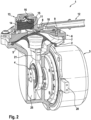
- the Fig.2 shows a first embodiment of the motor pump assembly 1 according to the invention.
- the motor pump assembly 1 has in contrast to the known embodiment Fig.1 via only a single membrane 2. This is set in motion by a single connecting rod 21, which is driven by the electric motor unit 3 via the eccentric drive 4 with a single eccentric.
- a counterweight 25 formed on the eccentric is used to balance the mass of the connecting rod 21 and thus reduces vibrations during operation.
- the pump housing 5 is joined and screwed to the motor unit 3 on one side and closed by a working chamber cover 6 on the other side, which is the top side in the figure.
- the membrane 2 is clamped in a sealing manner at its radially outer edge between the working chamber cover 6 and the pump housing 5 .
- a bulge on the edge of the membrane is pressed into a circumferential circular groove in the pump housing 5 .
- the workspace cover 6 is designed in several parts and has an upper cover 8 and a lower cover 9 . Between the upper cover 8 and the lower cover 9 an inlet valve 10 and an outlet valve 11 are arranged, both designed as elastic platelet valves.
- a pneumatic connection 12 for connecting a brake booster, for example, and a silencer unit 13 are arranged on the upper cover 8 .
- the spatial structures required for this are designed as integral components of the upper cover 8 .
- the Fig.3 forms the muffler unit from the Fig.2 enlarged from.
- the silencer unit 13 essentially fulfills two functions. Firstly, it serves to reduce noise in the air flow emerging from the working chamber 7 . For this purpose, it has a filter element 14 made of a porous material, with the filter element 14 largely occupying the entire interior of the muffler unit 13 .
- the muffler unit 13 prevents the ingress of water from the environment of the motor pump unit 1.
- a check valve 15 is provided in the muffler unit 13, which is arranged as a directional barrier between the filter element 14 and the environment - the atmosphere.
- the silencer element 13 has an air outlet opening 16 in a wall, with the check valve 15 being clamped between the filter element 14 and the wall with the air outlet opening 16 .
- the check valve is made of an elastomeric material and has a lip valve which is shaped as a so-called duckbill valve.
- the air emerging from the air outlet opening 16 of the silencer unit 13 enters a duct 17, where it is deflected and passed through two opposite outlet openings 18,19 (see Fig.4 ) finally escapes from the motor pump assembly 1 into the environment.
- the channel 17 improved both the noise reduction, additional deflection of the air flow, and water protection by serving as a baffle in front of the air outlet opening 16.
- the duct 17 has a flattened, essentially rectangular cross-section and is formed by a type of hood that is formed on the silencer unit 13 and is open on both sides.
- the channel 17 can be designed with any desired cross-section and course, have only one or more than two outlet openings 18,19, which are also not exclusively arranged opposite one another, but at an angle deviating from 180° to one another.
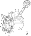
- the above-described embodiment of the motor pump assembly 1 according to the invention is shown in a spatial representation for clarification. Attention should be paid to the electrical connection plug 20 for supplying the motor unit 3 with power and, if necessary, control signals, which is arranged directly on the motor unit 3 .
- the connector plug 20 forms an interface for the electrical system of the vehicle.
- the connector plug 20 is integrated into the pump housing 5 .
- the contact (not shown) between the connector plug 20 and the motor unit 3 inside the pump housing 5 can be designed in such a way that this occurs automatically and automatically when the motor unit 3 is assembled with the pump housing 5 during the assembly of the motor-pump unit 1 - for example by means of corresponding plug or spring contacts arranged at defined positions in the two components.
Landscapes
- Engineering & Computer Science (AREA)
- Mechanical Engineering (AREA)
- General Engineering & Computer Science (AREA)
- Transportation (AREA)
- Physics & Mathematics (AREA)
- Fluid Mechanics (AREA)
- Reciprocating Pumps (AREA)
Description
- Die Erfindung betrifft ein Motorpumpenaggregat, insbesondere zur Unterdruckversorgung eines pneumatischen Bremskraftverstärkers für eine hydraulische PKW-Bremsanlage. Die modernen Fahrzeugantriebe stellen meist zu wenig bis gar keinen Unterdruck zur Verfügung, um einen pneumatischen Bremskraftverstärkern betreiben zu können. Dies macht den Einsatz von gesonderten Pumpenaggregaten zur Erzeugung vom erforderlichen Unterdruck erforderlich.
- Als besonders flexibel im Einsatz erweisen sich dabei Motorpumpenaggregate mit einer eigenen Antriebseinheit, da sie unabhängig vom Hauptantrieb bedarfsgemäß betrieben werden können. Besonders verbreitet sind dabei Flügelzellenpumpen und Doppelmembranpumpen mit zwei gegenüberliegenden elastomeren Membranen in Boxeranordnung, wie beispielsweise aus
WO 2007/134928 A1 bekannt. Die Doppelmembranpumpen haben gegenüber den Flügelzellenpumpen insbesondere Vorteile, dass sie auch bei hohen Temperaturen und in großen Höhen beim niedrigen Luftdruck zuverlässig funktionieren, außerdem eine steile Luftdurchsatz-Anlaufcharakteristik aufweisen. Allerdings sind sie auch meist schwerer, größer, komplexer aufgebaut und somit teurer als die Flügelzellenpumpen. Zudem benötigen derartige Konstruktionen oft komplexe Vorrichtungen zum Schutz vom Wassereindrang in den Innenraum, um Schäden am Motorpumpenaggregat und dem Bremskraftverstärker zu vermeiden. - Aus
US 4,743,169 A ist eine besonders einfach ansteuerbare Einkolben-Diafragmen-Vakuumpumpe mit einem federgesteuerten Ventil zur Einhaltung eines vorbestimmten Unterdruckniveaus im Verbraucher bekannt. Beim Erreichen eines bestimmten Unterdrucks im Verbraucher öffnet das Ventil und lässt Luft aus der Atmosphäre in eine Arbeitskammer hinein, wodurch die Pumpe in einen Quasi-Leerlauf schaltet. Eine derartige Pumpe ist jedoch ineffizient hinsichtlich ihren Energieverbrauchs und zudem vergleichsweise laut, da sie über keinerlei Schalldämpfungsmaßnahmen verfügt. - Es stellt sich daher die Aufgabe, ein Motorpumpenaggregat anzubieten, welches unter Einhaltung der Vorteile von Doppelmembranpumpen einfacher, kompakter und preiswerter ist.
- Die Aufgabe wird erfindungsgemäß durch die Merkmalskombination nach dem unabhängigen Anspruch 1 gelöst. Unteransprüche geben weitere erfindungsgemäße Ausführungen und Weiterbildungen an.
- Der erfindungsgemäße Aufbau eines hochintegrierten Aggregats mit einer einzigen Membran ermöglicht die Verwendung eines kleineren und leichteren Elektroantriebes, die Verringerung von Einzelteilen von einer erheblichen Reduzierung von Kosten, Gewicht und Montageaufwand. Kompaktere Außenabmessungen erlauben ein noch Packaging im Motorraum eines Kraftfahrzeugs.
- Ein pneumatischer Anschluss zum Verbinden des Arbeitsraumes des Motorpumpenaggregats mit dem Verbraucher wie beispielsweise Bremskraftverstärker kann besonders vorteilhaft direkt am Arbeitsraumdeckel in unmittelbarer Nähe zum Einlassventil angeordnet und insbesondere angeformt werden. Auf zusätzliche, den Wirkungsgrad mindernde Luftkanäle wird verzichtet, der Aufbau vom Pumpengehäuse erheblich vereinfacht. Zudem kann der pneumatische Anschluss in je nach vorliegenden Raumanforderungen flexibel angepasst werden, sowohl die Richtung und Position betreffend, als auch den Typ - beispielsweise als ein Stutzen, ein Bajonettverschluss, ein Schnellverschluss bzw. ein Quick Connector.
- Eine direkt an dem Arbeitsraumdeckel unmittelbar nach dem Auslassventil angeordnete und vorzugsweise integriert angeformte Schalldämpfereinheit mit einem porösen Filterelement ermöglicht eine besonders effiziente Geräuschminderung mit wenig Druckverlust und einem hohen Wirkungsgrad.
- In vorteilhafter Weiterbildung der Erfindung kann in der Schalldämpfereinheit zur Vermeidung von Wassereintritt ein Rückschlagventil vorgesehen sein, welches in Luftströmungsrichtung zwischen dem Filterelement und der Atmosphäre angeordnet und derart eingerichtet ist, dass es in Richtung Filterelement geschlossen ist. Dabei kann das Rückschlagventil kostengünstig aus einem elastomeren Werkstoff hergestellt und besonders einfach montierbar zwischen dem Filterelement und der Wand mit der Luftaustrittsöffnung in der Schalldämpfereinheit eingeklemmt sein.
- Ein feuchtes Filterelement verursacht meist einen erheblich erhöhen Druckverlust. Durch den Einsatz eines Rückschlagventils könne für das Filterelement kostengünstige und besonders effektiv schalldämpfende Werkstoffe ohne Rücksicht auf deren Saugfähigkeit zurückgegriffen und auf wasserabweisende Beschichtungen verzichtet werden.
- In einer besonders vorteilhaften Weiterbildung kann das Rückschlagventil als ein Lippenventil, insbesondere als ein Entenschnabelventil gestaltet sein. Eine derartige Ventilkonstruktion ist aerodynamischer und leiser als ein vergleichbares Flachventil, bietet eine wesentlich bessere Schutzwirkung vor dem Wassereindrang, ist gleichzeitig günstiger, leichter und hat einen geringeren Raumbedarf als mechanische federbelasteten Rückschlagventile mit einem Sperrkörper.
- In einer weiteren vorteilhaften Weiterbildung kann, der aus dem Filterelement und gegebenenfalls dem Rückschlagventil austretender Luftstrom, in einen Kanal eingeleitet werden, in dem er zunächst umgelenkt und erst dann in die Umgebung geleitet wird. Dabei bildet der Kanal eine zusätzliche Schutzvorrichtung gegen Wassereindrang, Verschmutzung und mechanische Beschädigungen, indem er einer Art Schwallwand vor der Luftaustrittsöffnung bildet, zusätzlich wird durch die Umlenkung des Luftstroms die Schalldämpfungswirkung weiter erhöht.
- Dabei kann der Kanal über nur eine, aber auch zwei und mehr Austrittsöffnungen verfügen, die in verschiedenen Winkeln zueinander angeordnet werden können. Dadurch kann beispielsweise eine vom Spritzwasser besonders geschützte Richtung für die Austrittsöffnung gezielt gewählt werden.
- In weiteren Weiterbildungen kann der elektrische Anschlussstecker zur Versorgung der Motoreinheit direkt an der Motoreinheit oder im Pumpengehäuse integriert vorgesehen werden. Besonders vorteilhaft erweist sich die Integration des Anschlusssteckers am Pumpengehäuse bei gleichzeitiger Auslegung der elektrischen Kontaktierung zur Motoreinheit derart, dass diese beim Zusammenfügen des Pumpengehäuses und der Motoreinheit während der Montage des Motorpumpenaggregats selbsttätig und zwangsweise zustande kommt - beispielsweise mittels an definierten Positionen in den beiden Komponenten angeordneten korrespondierenden Steck- oder Federkontakten. Hierdurch wird die Montage erheblich vereinfacht, Prozessschritte reduziert und Montagefehler - beispielsweise aufgrund vergessener Kontaktierung oder beschädigter Kabel - vermieden.
- Weitere Einzelheiten, Merkmale, Vorteile und Anwendungsmöglichkeiten der Erfindung gehen aus Unteransprüchen zusammen mit der Beschreibung und anhand der Figuren hervor. Übereinstimmende Komponenten und Konstruktionselemente werden nach Möglichkeit mit gleichen Bezugszeichen versehen.
- Auf detaillierte Beschreibung von Grundfunktionen eines gattungsgemäßen Motorpumpenaggregats wird dabei weitgehend verzichtet, da ausreichend bekannt.
- Nachstehend zeigt:
-
Fig. 1 eine bekannte Ausführung eines Doppelmembranpumpe. -
Fig.2 eine erste erfindungsgemäße Ausführungsform des Motorpumpenaggregats mit Teilausschnitt. -
Fig.3 Eine vergrößerte Ansicht der Schaldämpfereinheit der Ausführung nachFig.2 . -
Fig.4 Eine räumliche Ansicht eines erfindungsgemäßen Motorpumpenaggregats. -
Fig.5 Eine räumliche Ansicht einer anderen erfindungsgemäßen Ausführungsform eines Motorpumpenaggregats und die Vergrößerte Darstellung des zugehörigen Anschlusssteckers. -
Fig. 1 zeigt eine bekannte Ausführung eines als eine Doppelmembranpumpe aufgebauten Motorpumpenaggregats. Eine Motoreinheit 3 treibt über einen Exzentertrieb 4 zwei Pleuel 21 an, welche die Bewegung an zwei gegenüberliegend angeordneten Membranen 2 übermitteln. Das Pumpengehäuse 5 wird von beiden Seiten durch jeweils einen Arbeitsraumdeckel 6 verschlossen. Zwischen jedem Arbeitsraumdeckel 6 und dem Pumpengehäuse 5 ist je eine elastomere Membran 2 luftdicht eingespannt, so dass jeweils zwischen der Membran 2und dem Arbeitsraumdeckel 6 ein Arbeitsraum 7 mit einem veränderbaren Volumen ausgebildet ist. Jeder Arbeitsraumdeckel 6 ist mehrteilig mit einem Oberdeckel 8 und einem Unterdeckel 9 sowie zwischen dem Oberdeckel 8 und dem Unterdeckel 9 angeordneten, nicht gezeigten Einlass- 10 und Auslassventilen 11, welche die Luftzirkulation durch den Arbeitsraum 7 steuern, ausgebildet. Die Luft zu den Einlassventilen wird von einem zentralen, am Pumpengehäuse 5 angeordneten Luftanschluss 23 über nicht gezeigte, im Pumpengehäuse 5 integrierte Luftkanäle zugeleitet. Die Luft von den Auslassventilen wird über weitere Kanäle in den Innenraum von dem Pumpengehäuse 5 und von dort durch die am Pumpengehäuse 5 angeordnete Luftauslasseinheit 22 in die Atmosphäre geleitet. Über eine aus der Motoreinheit 3 herausgeführte Kabelleitung 24 wird der elektrische Antrieb mit Strom versorgt und gesteuert. - Die
Fig.2 zeigt eine erste erfindungsgemäße Ausführungsform des Motorpumpenaggregates 1. Das Motorpumpenaggregat 1 verfügt im Unterschied zu der bekannten Ausführung nachFig.1 über lediglich eine einzige Membran 2. Diese wird von einem einzigen Pleuel 21 in Bewegung versetzt, der von der elektrischen Motoreinheit 3 über den Exzentertrieb 4 mit einem einzigen Exzenter angetrieben ist. Ein am Exzenter angeformtes Ausgleichsgewicht 25 dient dem Massenausgleich zum Pleuel 21 und sorgt so für Reduzierung von Vibrationen im Betrieb. - Das Pumpengehäuse 5 ist an einer Seite mit der Motoreinheit 3 zusammengefügt und verschraubt, an einer anderen, im Bild oberen Seite von einem Arbeitsraumdeckel 6 verschlossen. Zwischen dem Arbeitsraumdeckel 6 und dem Pumpengehäuse 5 ist die Membran 2 an ihrem radial äußeren Rand dichtend eingespannt. Dabei wird eine Wulst am Membranenrand in eine umlaufende kreisförmige Nut im Pumpengehäuse 5 eingepresst.
- Der Arbeitsraumdeckel 6 ist mehrteilig ausgebildet und weist einen Oberdeckel 8 und einen Unterdeckel 9 auf. Zwischen dem Oberdeckel 8 und dem Unterdeckel 9 ist ein Einlassventil 10 und ein Auslassventil 11 angeordnet, die beiden als elastische Plättchenventile gestaltet.
- An dem Oberdeckel 8 sind ein pneumatischer Anschluss 12 zum anschließen beispielsweise eines Bremskraftverstärkers, sowie eine Schalldämpfereinheit 13 angeordnet. In der gezeigten Ausführung sind die dafür erforderlichen räumlichen Gebilde als integrative Bestandteile des Oberdeckels 8 gestaltet.
- Die
Fig.3 bildet die Schalldämpfereinheit aus derFig.2 vergrößert ab. Die Schalldämpfereinheit 13 erfüllt im Wesentlichen zwei Funktionen. Erstens dient sie zur Schallreduzierung im aus der Arbeitskammer 7 austretenden Luftstrom. Zu diesem Zweck verfügt sie über sie ein Filterelement 14 aus einem porösen Werkstoff, wobei das Filterelement 14 weitgehend den gesamten Innenraum der Schalldämpfereinheit 13 einnimmt. - Zweitens verhindert die Schalldämpfereinheit 13 den Wassereindrang aus der Umgebung des Motorpumpenaggregats 1. Zu diesem Zweck ist in der Schalldämpfereinheit 13 ein Rückschlagventil 15 vorgesehen, der als eine richtungsabhängige Sperre zwischen dem Filterelement 14 und der Umgebung - der Atmosphäre - angeordnet ist. Zum Austreten der Luft weist das Schalldämpferelement 13 in einer Wand eine Luftaustrittsöffnung 16 auf, dabei ist das Rückschlagventil 15 zwischen dem Filterelement 14 und der Wand mit der Luftaustrittsöffnung 16 eingeklemmt. Das Rückschlagventil ist aus einem elastomeren Werkstoff ausgebildet und verfügt über ein Lippenventil, welches als ein sogenanntes Entenschnabelventil geformt ist. Beim Austreten der Luft aus der Arbeitskammer 7 während eines Hubes der Membran 2, öffnen die Lippen des Ventils sich elastisch vorspannend aufgrund des filterseitig höheren Luftdruckes und schließen sich durch die aufgebaute Vorspannung, sobald der Luftdruck auf beiden Seiten des Ventils wieder ausgeglichen ist.
- Die aus der Luftaustrittsöffnung 16 der Schalldämpfereinheit 13 austretende Luft tritt in einen Kanal 17, wo sie umgelenkt wird und durch zwei gegenüberliegende Austrittsöffnungen 18,19 (siehe
Fig.4 ) schließlich aus dem Motorpumpenaggregat 1 in die Umgebung austritt. Der Kanal 17 verbessert sowohl die Schallreduzierung zusätzlich Umlenkung des Luftstroms, als aus den Wasserschutz, indem er als Schwallwand vor der Luftaustrittsöffnung 16 dient. - In der abgebildeten Ausführung weist der Kanal 17 einen abgeflachten, im Wesentlichen rechteckigen Querschnitt auf und ist durch eine Art an der Schalldämpfereinheit 13 angeformte beidseitig offene Haube gebildet. Innerhalb der Erfindung kann der Kanal 17 jedoch mit einem beliebigen Querschnitt und Verlauf gestaltet sein, nur eine oder mehr als zwei Austrittsöffnungen 18,19 aufweisen, welche zudem nicht ausschließlich gegenüber, sondern in einem von 180°abweichenden Winkel zueinander angeordnet sind.
- In der
Fig.4 ist die vorstehend beschriebene Ausführung des erfindungsgemäßen Motorpumpenaggregats 1 zur Verdeutlichung in einer räumlichen Darstellung abgebildet. Zu beachten ist der elektrische Anschlussstecker 20 zur Versorgung der Motoreinheit 3 mit Strom und gegebenenfalls Steuersignalen, der direkt an der Motoreinheit 3 angeordnet ist. Der Anschlussstecker 20 bildet eine Schnittstelle für das elektrische Bordnetz des Fahrzeugs. - Bei der in der
Fig.5 abgebildeten weiteren erfindungsgemäßen Ausführungsform ist der Anschlussstecker 20 in das Pumpengehäuse 5 integriert. Dabei kann die (nicht gezeigte) Kontaktierung zwischen dem Anschlussstecker 20 und der Motoreinheit 3 im Inneren des Pumpengehäuses 5 so gestaltet sein, das diese beim Zusammenfügen der Motoreinheit 3 mit dem Pumpengehäuse 5 während der Montage des Motorpumpenaggregats 1 selbsttätig und zwangsweise zustande kommt - beispielsweise mittels an definierten Positionen in den beiden Komponenten angeordneten korrespondierenden Steck- oder Federkontakten. -
- 1
- Motorpumpenaggregat
- 2
- Membran
- 3
- Motoreinheit
- 4
- Exzentertrieb
- 5
- Pumpengehäuse
- 6
- Arbeitsraumdeckel
- 7
- Arbeitsraum
- 8
- Oberdeckel
- 9
- Unterdeckel
- 10
- Einlassventil
- 11
- Auslassventil
- 12
- Anschluss
- 13
- Schalldämpfereinheit
- 14
- Filterelement
- 15
- Rückschlagventil
- 16
- Luftaustrittsöffnung
- 17
- Kanal
- 18
- Ausgangsöffnung
- 19
- Ausgangsöffnung
- 20
- Anschlussstecker
- 21
- Pleuel
- 22
- Luftauslasseinheit
- 23
- Luftanschluss
- 24
- Elektrokabel
- 25
- Ausgleichsgewicht
Claims (10)
- Motorpumpenaggregat (1) zur Unterdruckversorgung insbesondere eines pneumatischen Bremskraftverstärkers, wobei:- das Motorpumpenaggregat (1) als eine Membranpumpe mit einer einzigen elastomeren Membran (2) ausgebildet ist,- die Membran (2) durch eine elektrisch betriebene Motoreinheit (3) mittels eines Exzentertriebes (4) bewegt ist,- das Motorpumpenaggregat (1) ein Pumpengehäuse (5) und einen Arbeitsraumdeckel (6) aufweist und die Membran (2) am ihren radialen Außenrand zwischen dem Pumpengehäuse (5) und dem Arbeitsraumdeckel (6) dichtend eingeklemmt ist, so dass zwischen der Membran (2) und dem Arbeitsraumdeckel (6) ein Arbeitsraum (7) mit einen veränderbaren Volumen ausgebildet ist,- der Arbeitsraumdeckel (6) mehrteilig mit einem Oberdeckel (8) und einem Unterdeckel (9) sowie zwischen dem Oberdeckel (8) und dem Unterdeckel (9) angeordneten Einlass-(10) und Auslassventil (11), welche die Luftzirkulation durch den Arbeitsraum (7) steuern ausgebildet ist dadurch gekennzeichnet, dass ein pneumatischer Anschluss (12) zum Einlassen der Luft in den Arbeitsraum (7) sowie eine Schalldämpfereinheit (13) zum geräuschmindernden Auslassen der Luft aus dem Arbeitsraum (7) in die Atmosphäre vorgesehen sind, wobei der Anschluss (12) und die Schalldämpfereinheit (13) am Arbeitsraumdeckel (6) angeordnet sind.
- Motorpumpenaggregat (1) nach Anspruch 1 dadurch gekennzeichnet, dass der Anschluss (12) und die Schalldämpfereinheit (13) integral mit dem Arbeitsraumdeckel (6) verbunden sind.
- Motorpumpenaggregat (1) nach Anspruch 1 oder 2 dadurch gekennzeichnet, dass die Schalldämpfereinheit (13) ein Filterelement (14) aus einem porösen Werkstoff und ein Rückschlagventil (15) aufweist, wobei das Rückschlagventil (15) in Luftströmungsrichtung zwischen dem Filterelement (14) und der Atmosphäre angeordnet ist.
- Motorpumpenaggregat (1) nach Anspruch 3 dadurch gekennzeichnet, dass das Rückschlagventil (15) aus einem Elastomerwerkstoff als ein Lippenventil, insbesondere als Entenschnabelventil gestaltet ist.
- Motorpumpenaggregat (1) nach Anspruch 3 dadurch gekennzeichnet, dass das Rückschlagventil (15) in der Schalldämpfereinheit (13) zwischen dem Filterelement (14) und einer Wand mit einer Luftaustrittsöffnung (16) eingeklemmt ist.
- Motorpumpenaggregat (1) nach wenigstens einem der Ansprüche 3 bis 5 dadurch gekennzeichnet, dass ein Kanal (17) zum Umlenken eines aus dem Rückschlagventil (15) austretenden Luftstroms vorgesehen ist.
- Motorpumpenaggregat (1) nach Anspruch 6 dadurch gekennzeichnet, dass der Kanal (17) zur Umlenkung des Luftstroms in wenigstens zwei verschiedene Richtungen ausgebildet ist, indem er unterschiedlich gerichtete Ausgangsöffnungen (18, 19) aufweist.
- Motorpumpenaggregat (1) nach Anspruch 1 dadurch gekennzeichnet, dass ein elektrischer Anschlussstecker (20) zur Versorgung der Motoreinheit (3) im Pumpengehäuse (5) integriert vorgesehen ist.
- Motorpumpenaggregat (1) nach Anspruch 8 dadurch gekennzeichnet, dass elektrische Kontaktierung zwischen dem Anschlussstecker (20) und der Motoreinheit (3) beim Zusammenfügen des Pumpengehäuses (5) und der Motoreinheit (3) zwangsweise selbststätig erzeugt ist.
- Motorpumpenaggregat (1) nach Anspruch 1 dadurch gekennzeichnet, dass ein elektrischer Anschlussstecker (20) zur Versorgung der Motoreinheit (3) an der Motoreinheit (3) angeordnet ist.
Applications Claiming Priority (2)
| Application Number | Priority Date | Filing Date | Title |
|---|---|---|---|
| DE102015205059.9A DE102015205059A1 (de) | 2015-03-20 | 2015-03-20 | Motorpumpenaggregat mit einer einzelnen elastischen Membran |
| PCT/EP2016/055556 WO2016150763A1 (de) | 2015-03-20 | 2016-03-15 | Motorpumpenaggregat mit einer einzelnen elastischen membran |
Publications (2)
| Publication Number | Publication Date |
|---|---|
| EP3271581A1 EP3271581A1 (de) | 2018-01-24 |
| EP3271581B1 true EP3271581B1 (de) | 2023-05-10 |
Family
ID=55527928
Family Applications (1)
| Application Number | Title | Priority Date | Filing Date |
|---|---|---|---|
| EP16709939.9A Active EP3271581B1 (de) | 2015-03-20 | 2016-03-15 | Motorpumpenaggregat mit einer einzelnen elastischen membran |
Country Status (6)
| Country | Link |
|---|---|
| US (1) | US10508649B2 (de) |
| EP (1) | EP3271581B1 (de) |
| KR (1) | KR20170108166A (de) |
| CN (1) | CN209092728U (de) |
| DE (1) | DE102015205059A1 (de) |
| WO (1) | WO2016150763A1 (de) |
Families Citing this family (3)
| Publication number | Priority date | Publication date | Assignee | Title |
|---|---|---|---|---|
| CN109538451B (zh) * | 2019-01-14 | 2024-03-26 | 沈阳远大压缩机有限公司 | 超高压隔膜压缩机液压引导式密封膜头 |
| US11767840B2 (en) | 2021-01-25 | 2023-09-26 | Ingersoll-Rand Industrial U.S. | Diaphragm pump |
| CN115095510B (zh) * | 2022-07-19 | 2023-06-23 | 兰州工业学院 | 一种隔膜压缩机 |
Citations (2)
| Publication number | Priority date | Publication date | Assignee | Title |
|---|---|---|---|---|
| US4743169A (en) * | 1984-08-25 | 1988-05-10 | Aisin Seiki Kabushiki Kaisha | Diaphragm-type vacuum pump device |
| DE4118652A1 (de) * | 1991-02-02 | 1992-08-06 | Knf Neuberger Gmbh | Pumpe, vorzugsweise membranpumpe |
Family Cites Families (10)
| Publication number | Priority date | Publication date | Assignee | Title |
|---|---|---|---|---|
| US5017100A (en) * | 1990-04-09 | 1991-05-21 | Arkans Edward J | Integral pump and check valve apparatus |
| US5782621A (en) * | 1996-04-22 | 1998-07-21 | Mission Pharmacal Company | Manual pump with inherent vacuum limit |
| DE19912926A1 (de) | 1999-03-22 | 2000-09-28 | Bock Gmbh & Co Kaeltemaschinen | Kolbenverdichter für Kältemittel |
| DE29919188U1 (de) * | 1999-11-02 | 2000-01-27 | SP Jürgen Schwarzer GmbH u. Co KG, 45276 Essen | Membranpumpe |
| JP2002371968A (ja) * | 2001-06-12 | 2002-12-26 | Techno Takatsuki Co Ltd | 電磁振動型ポンプおよびポンプユニット |
| DE102007005019A1 (de) * | 2006-05-18 | 2007-12-06 | Continental Teves Ag & Co. Ohg | Membranpumpe |
| DE102009054502A1 (de) * | 2008-12-19 | 2010-06-24 | Continental Teves Ag & Co. Ohg | Motor-Pumpenaggregat |
| DE102010013106A1 (de) * | 2010-03-26 | 2011-09-29 | Thomas Magnete Gmbh | Pumpe |
| DE102013201718A1 (de) * | 2012-02-01 | 2013-08-01 | Continental Teves Ag & Co. Ohg | Elektromotorisch antreibbares Pumpenaggregat |
| BR102012025279B1 (pt) * | 2012-10-03 | 2021-09-21 | Embraco Indústria De Compressores E Soluções Em Refrigeração Ltda | Compressor de refrigeração tendo um sistema de descarga de gás |
-
2015
- 2015-03-20 DE DE102015205059.9A patent/DE102015205059A1/de not_active Withdrawn
-
2016
- 2016-03-15 EP EP16709939.9A patent/EP3271581B1/de active Active
- 2016-03-15 WO PCT/EP2016/055556 patent/WO2016150763A1/de not_active Ceased
- 2016-03-15 KR KR1020177025210A patent/KR20170108166A/ko not_active Ceased
- 2016-03-15 CN CN201690000584.5U patent/CN209092728U/zh not_active Expired - Lifetime
- 2016-03-15 US US15/554,088 patent/US10508649B2/en active Active
Patent Citations (2)
| Publication number | Priority date | Publication date | Assignee | Title |
|---|---|---|---|---|
| US4743169A (en) * | 1984-08-25 | 1988-05-10 | Aisin Seiki Kabushiki Kaisha | Diaphragm-type vacuum pump device |
| DE4118652A1 (de) * | 1991-02-02 | 1992-08-06 | Knf Neuberger Gmbh | Pumpe, vorzugsweise membranpumpe |
Also Published As
| Publication number | Publication date |
|---|---|
| US20180073500A1 (en) | 2018-03-15 |
| EP3271581A1 (de) | 2018-01-24 |
| KR20170108166A (ko) | 2017-09-26 |
| WO2016150763A1 (de) | 2016-09-29 |
| US10508649B2 (en) | 2019-12-17 |
| DE102015205059A1 (de) | 2016-09-22 |
| CN209092728U (zh) | 2019-07-12 |
Similar Documents
| Publication | Publication Date | Title |
|---|---|---|
| EP2379888B1 (de) | Motor-pumpenaggregat | |
| EP2193058B1 (de) | Motor-pumpenaggregat | |
| EP1984221B1 (de) | Motor-pumpenaggregat | |
| EP2809951B1 (de) | Elektromotorisch antreibbares pumpenaggregat | |
| EP2512889B1 (de) | Motor-pumpenaggregat | |
| EP2646302B1 (de) | Motor-pumpenaggregat | |
| DE102016217252B4 (de) | Vorrichtung zur Bereitstellung eines pneumatischen Druckmittels durch eine Druckmittelquelle für mindestens eine Druckmittelkammer insbesondere eines Fahrzeugsitzes eines Kraftfahrzeugs, Fahrzeugsitz und Kraftfahrzeug | |
| DE102015205059A1 (de) | Motorpumpenaggregat mit einer einzelnen elastischen Membran | |
| EP2568180A1 (de) | Flügelzellenpumpe | |
| DE102007020538A1 (de) | Motor-Pumpenaggregat | |
| DE102015118111A1 (de) | Elektrische Vakuumpumpe, insbesondere zur Anordnung in einem Fahrzeug | |
| WO2019034256A1 (de) | Kfz-vakuumpumpen-anordnung | |
| WO2013149939A2 (de) | Elektromotorisch angetriebenes pumpenaggregat | |
| DE102006060645B4 (de) | Motor-Pumpenaggregat | |
| EP1588054B1 (de) | Pumpe | |
| DE102011082749A1 (de) | Bremsbetätigungseinheit für eine Kraftfahrzeugbremsanlage und Motor-Pumpenaggregat zur Bereitstellung von Unterdruck für eine Bremsbetätigungseinheit einer Kraftfahrzeugbremsanlage | |
| WO2017220141A1 (de) | Kfz-vakuumpumpen-anordnung | |
| DE102011006525A1 (de) | Motor-Pumpenaggregat | |
| DE102015205190A1 (de) | Motorpumpenaggregat |
Legal Events
| Date | Code | Title | Description |
|---|---|---|---|
| STAA | Information on the status of an ep patent application or granted ep patent |
Free format text: STATUS: THE INTERNATIONAL PUBLICATION HAS BEEN MADE |
|
| PUAI | Public reference made under article 153(3) epc to a published international application that has entered the european phase |
Free format text: ORIGINAL CODE: 0009012 |
|
| STAA | Information on the status of an ep patent application or granted ep patent |
Free format text: STATUS: REQUEST FOR EXAMINATION WAS MADE |
|
| 17P | Request for examination filed |
Effective date: 20171020 |
|
| AK | Designated contracting states |
Kind code of ref document: A1 Designated state(s): AL AT BE BG CH CY CZ DE DK EE ES FI FR GB GR HR HU IE IS IT LI LT LU LV MC MK MT NL NO PL PT RO RS SE SI SK SM TR |
|
| AX | Request for extension of the european patent |
Extension state: BA ME |
|
| RIN1 | Information on inventor provided before grant (corrected) |
Inventor name: MILISIC, LAZAR Inventor name: MESSNER, ADRIAN Inventor name: GONZALEZ, JOSE Inventor name: NIEPENBERG, MARCEL Inventor name: PETZOLD, FALK Inventor name: WIEBE, PAUL Inventor name: BACHER, JENS Inventor name: TOQUERO, RICARDO Inventor name: JUERGING, MICHAEL Inventor name: MEYER, ULRIKE Inventor name: KREBS, STEPHAN Inventor name: OEFFNER, THOMAS Inventor name: FELLINGER, ROLF Inventor name: RUEFFER, MANFRED Inventor name: KOPPEL, HANS-MICHAEL Inventor name: BREITKOPF, MARTINA Inventor name: IMHOF, STEFAN Inventor name: KREH, HEINRICH |
|
| DAV | Request for validation of the european patent (deleted) | ||
| DAX | Request for extension of the european patent (deleted) | ||
| RAP1 | Party data changed (applicant data changed or rights of an application transferred) |
Owner name: CONTINENTAL TEVES AG & CO. OHG |
|
| STAA | Information on the status of an ep patent application or granted ep patent |
Free format text: STATUS: EXAMINATION IS IN PROGRESS |
|
| 17Q | First examination report despatched |
Effective date: 20210426 |
|
| RAP1 | Party data changed (applicant data changed or rights of an application transferred) |
Owner name: CONTINENTAL AUTOMOTIVE TECHNOLOGIES GMBH |
|
| REG | Reference to a national code |
Ref country code: DE Ref legal event code: R079 Ref document number: 502016015744 Country of ref document: DE Free format text: PREVIOUS MAIN CLASS: F04B0039000000 Ipc: F04B0035010000 |
|
| GRAP | Despatch of communication of intention to grant a patent |
Free format text: ORIGINAL CODE: EPIDOSNIGR1 |
|
| RIC1 | Information provided on ipc code assigned before grant |
Ipc: F04B 45/047 20060101ALI20221117BHEP Ipc: F04B 39/00 20060101ALI20221117BHEP Ipc: F04B 45/04 20060101ALI20221117BHEP Ipc: F04B 39/12 20060101ALI20221117BHEP Ipc: F04B 35/04 20060101ALI20221117BHEP Ipc: F04B 35/01 20060101AFI20221117BHEP |
|
| STAA | Information on the status of an ep patent application or granted ep patent |
Free format text: STATUS: GRANT OF PATENT IS INTENDED |
|
| INTG | Intention to grant announced |
Effective date: 20221222 |
|
| GRAS | Grant fee paid |
Free format text: ORIGINAL CODE: EPIDOSNIGR3 |
|
| GRAA | (expected) grant |
Free format text: ORIGINAL CODE: 0009210 |
|
| STAA | Information on the status of an ep patent application or granted ep patent |
Free format text: STATUS: THE PATENT HAS BEEN GRANTED |
|
| AK | Designated contracting states |
Kind code of ref document: B1 Designated state(s): AL AT BE BG CH CY CZ DE DK EE ES FI FR GB GR HR HU IE IS IT LI LT LU LV MC MK MT NL NO PL PT RO RS SE SI SK SM TR |
|
| REG | Reference to a national code |
Ref country code: GB Ref legal event code: FG4D Free format text: NOT ENGLISH |
|
| REG | Reference to a national code |
Ref country code: AT Ref legal event code: REF Ref document number: 1566905 Country of ref document: AT Kind code of ref document: T Effective date: 20230515 Ref country code: CH Ref legal event code: EP |
|
| REG | Reference to a national code |
Ref country code: DE Ref legal event code: R096 Ref document number: 502016015744 Country of ref document: DE |
|
| REG | Reference to a national code |
Ref country code: IE Ref legal event code: FG4D Free format text: LANGUAGE OF EP DOCUMENT: GERMAN |
|
| REG | Reference to a national code |
Ref country code: LT Ref legal event code: MG9D |
|
| REG | Reference to a national code |
Ref country code: NL Ref legal event code: MP Effective date: 20230510 |
|
| PG25 | Lapsed in a contracting state [announced via postgrant information from national office to epo] |
Ref country code: SE Free format text: LAPSE BECAUSE OF FAILURE TO SUBMIT A TRANSLATION OF THE DESCRIPTION OR TO PAY THE FEE WITHIN THE PRESCRIBED TIME-LIMIT Effective date: 20230510 Ref country code: PT Free format text: LAPSE BECAUSE OF FAILURE TO SUBMIT A TRANSLATION OF THE DESCRIPTION OR TO PAY THE FEE WITHIN THE PRESCRIBED TIME-LIMIT Effective date: 20230911 Ref country code: NO Free format text: LAPSE BECAUSE OF FAILURE TO SUBMIT A TRANSLATION OF THE DESCRIPTION OR TO PAY THE FEE WITHIN THE PRESCRIBED TIME-LIMIT Effective date: 20230810 Ref country code: NL Free format text: LAPSE BECAUSE OF FAILURE TO SUBMIT A TRANSLATION OF THE DESCRIPTION OR TO PAY THE FEE WITHIN THE PRESCRIBED TIME-LIMIT Effective date: 20230510 Ref country code: ES Free format text: LAPSE BECAUSE OF FAILURE TO SUBMIT A TRANSLATION OF THE DESCRIPTION OR TO PAY THE FEE WITHIN THE PRESCRIBED TIME-LIMIT Effective date: 20230510 |
|
| PG25 | Lapsed in a contracting state [announced via postgrant information from national office to epo] |
Ref country code: RS Free format text: LAPSE BECAUSE OF FAILURE TO SUBMIT A TRANSLATION OF THE DESCRIPTION OR TO PAY THE FEE WITHIN THE PRESCRIBED TIME-LIMIT Effective date: 20230510 Ref country code: PL Free format text: LAPSE BECAUSE OF FAILURE TO SUBMIT A TRANSLATION OF THE DESCRIPTION OR TO PAY THE FEE WITHIN THE PRESCRIBED TIME-LIMIT Effective date: 20230510 Ref country code: LV Free format text: LAPSE BECAUSE OF FAILURE TO SUBMIT A TRANSLATION OF THE DESCRIPTION OR TO PAY THE FEE WITHIN THE PRESCRIBED TIME-LIMIT Effective date: 20230510 Ref country code: LT Free format text: LAPSE BECAUSE OF FAILURE TO SUBMIT A TRANSLATION OF THE DESCRIPTION OR TO PAY THE FEE WITHIN THE PRESCRIBED TIME-LIMIT Effective date: 20230510 Ref country code: IS Free format text: LAPSE BECAUSE OF FAILURE TO SUBMIT A TRANSLATION OF THE DESCRIPTION OR TO PAY THE FEE WITHIN THE PRESCRIBED TIME-LIMIT Effective date: 20230910 Ref country code: HR Free format text: LAPSE BECAUSE OF FAILURE TO SUBMIT A TRANSLATION OF THE DESCRIPTION OR TO PAY THE FEE WITHIN THE PRESCRIBED TIME-LIMIT Effective date: 20230510 Ref country code: GR Free format text: LAPSE BECAUSE OF FAILURE TO SUBMIT A TRANSLATION OF THE DESCRIPTION OR TO PAY THE FEE WITHIN THE PRESCRIBED TIME-LIMIT Effective date: 20230811 |
|
| PG25 | Lapsed in a contracting state [announced via postgrant information from national office to epo] |
Ref country code: FI Free format text: LAPSE BECAUSE OF FAILURE TO SUBMIT A TRANSLATION OF THE DESCRIPTION OR TO PAY THE FEE WITHIN THE PRESCRIBED TIME-LIMIT Effective date: 20230510 |
|
| PG25 | Lapsed in a contracting state [announced via postgrant information from national office to epo] |
Ref country code: SK Free format text: LAPSE BECAUSE OF FAILURE TO SUBMIT A TRANSLATION OF THE DESCRIPTION OR TO PAY THE FEE WITHIN THE PRESCRIBED TIME-LIMIT Effective date: 20230510 |
|
| PG25 | Lapsed in a contracting state [announced via postgrant information from national office to epo] |
Ref country code: SM Free format text: LAPSE BECAUSE OF FAILURE TO SUBMIT A TRANSLATION OF THE DESCRIPTION OR TO PAY THE FEE WITHIN THE PRESCRIBED TIME-LIMIT Effective date: 20230510 Ref country code: SK Free format text: LAPSE BECAUSE OF FAILURE TO SUBMIT A TRANSLATION OF THE DESCRIPTION OR TO PAY THE FEE WITHIN THE PRESCRIBED TIME-LIMIT Effective date: 20230510 Ref country code: RO Free format text: LAPSE BECAUSE OF FAILURE TO SUBMIT A TRANSLATION OF THE DESCRIPTION OR TO PAY THE FEE WITHIN THE PRESCRIBED TIME-LIMIT Effective date: 20230510 Ref country code: EE Free format text: LAPSE BECAUSE OF FAILURE TO SUBMIT A TRANSLATION OF THE DESCRIPTION OR TO PAY THE FEE WITHIN THE PRESCRIBED TIME-LIMIT Effective date: 20230510 Ref country code: DK Free format text: LAPSE BECAUSE OF FAILURE TO SUBMIT A TRANSLATION OF THE DESCRIPTION OR TO PAY THE FEE WITHIN THE PRESCRIBED TIME-LIMIT Effective date: 20230510 Ref country code: CZ Free format text: LAPSE BECAUSE OF FAILURE TO SUBMIT A TRANSLATION OF THE DESCRIPTION OR TO PAY THE FEE WITHIN THE PRESCRIBED TIME-LIMIT Effective date: 20230510 |
|
| REG | Reference to a national code |
Ref country code: DE Ref legal event code: R097 Ref document number: 502016015744 Country of ref document: DE |
|
| REG | Reference to a national code |
Ref country code: DE Ref legal event code: R081 Ref document number: 502016015744 Country of ref document: DE Owner name: CONTINENTAL AUTOMOTIVE TECHNOLOGIES GMBH, DE Free format text: FORMER OWNER: CONTINENTAL AUTOMOTIVE TECHNOLOGIES GMBH, 30165 HANNOVER, DE Ref country code: DE Ref legal event code: R081 Ref document number: 502016015744 Country of ref document: DE Owner name: AUMOVIO GERMANY GMBH, DE Free format text: FORMER OWNER: CONTINENTAL AUTOMOTIVE TECHNOLOGIES GMBH, 30165 HANNOVER, DE |
|
| PLBE | No opposition filed within time limit |
Free format text: ORIGINAL CODE: 0009261 |
|
| STAA | Information on the status of an ep patent application or granted ep patent |
Free format text: STATUS: NO OPPOSITION FILED WITHIN TIME LIMIT |
|
| 26N | No opposition filed |
Effective date: 20240213 |
|
| PG25 | Lapsed in a contracting state [announced via postgrant information from national office to epo] |
Ref country code: SI Free format text: LAPSE BECAUSE OF FAILURE TO SUBMIT A TRANSLATION OF THE DESCRIPTION OR TO PAY THE FEE WITHIN THE PRESCRIBED TIME-LIMIT Effective date: 20230510 |
|
| PG25 | Lapsed in a contracting state [announced via postgrant information from national office to epo] |
Ref country code: SI Free format text: LAPSE BECAUSE OF FAILURE TO SUBMIT A TRANSLATION OF THE DESCRIPTION OR TO PAY THE FEE WITHIN THE PRESCRIBED TIME-LIMIT Effective date: 20230510 Ref country code: IT Free format text: LAPSE BECAUSE OF FAILURE TO SUBMIT A TRANSLATION OF THE DESCRIPTION OR TO PAY THE FEE WITHIN THE PRESCRIBED TIME-LIMIT Effective date: 20230510 |
|
| REG | Reference to a national code |
Ref country code: CH Ref legal event code: PL |
|
| PG25 | Lapsed in a contracting state [announced via postgrant information from national office to epo] |
Ref country code: BG Free format text: LAPSE BECAUSE OF FAILURE TO SUBMIT A TRANSLATION OF THE DESCRIPTION OR TO PAY THE FEE WITHIN THE PRESCRIBED TIME-LIMIT Effective date: 20230510 |
|
| PG25 | Lapsed in a contracting state [announced via postgrant information from national office to epo] |
Ref country code: LU Free format text: LAPSE BECAUSE OF NON-PAYMENT OF DUE FEES Effective date: 20240315 |
|
| PG25 | Lapsed in a contracting state [announced via postgrant information from national office to epo] |
Ref country code: MC Free format text: LAPSE BECAUSE OF FAILURE TO SUBMIT A TRANSLATION OF THE DESCRIPTION OR TO PAY THE FEE WITHIN THE PRESCRIBED TIME-LIMIT Effective date: 20230510 |
|
| GBPC | Gb: european patent ceased through non-payment of renewal fee |
Effective date: 20240315 |
|
| PG25 | Lapsed in a contracting state [announced via postgrant information from national office to epo] |
Ref country code: MC Free format text: LAPSE BECAUSE OF FAILURE TO SUBMIT A TRANSLATION OF THE DESCRIPTION OR TO PAY THE FEE WITHIN THE PRESCRIBED TIME-LIMIT Effective date: 20230510 Ref country code: LU Free format text: LAPSE BECAUSE OF NON-PAYMENT OF DUE FEES Effective date: 20240315 Ref country code: BG Free format text: LAPSE BECAUSE OF FAILURE TO SUBMIT A TRANSLATION OF THE DESCRIPTION OR TO PAY THE FEE WITHIN THE PRESCRIBED TIME-LIMIT Effective date: 20230510 |
|
| REG | Reference to a national code |
Ref country code: BE Ref legal event code: MM Effective date: 20240331 |
|
| PG25 | Lapsed in a contracting state [announced via postgrant information from national office to epo] |
Ref country code: BE Free format text: LAPSE BECAUSE OF NON-PAYMENT OF DUE FEES Effective date: 20240331 |
|
| PG25 | Lapsed in a contracting state [announced via postgrant information from national office to epo] |
Ref country code: GB Free format text: LAPSE BECAUSE OF NON-PAYMENT OF DUE FEES Effective date: 20240315 |
|
| PG25 | Lapsed in a contracting state [announced via postgrant information from national office to epo] |
Ref country code: FR Free format text: LAPSE BECAUSE OF NON-PAYMENT OF DUE FEES Effective date: 20240331 |
|
| PG25 | Lapsed in a contracting state [announced via postgrant information from national office to epo] |
Ref country code: IE Free format text: LAPSE BECAUSE OF NON-PAYMENT OF DUE FEES Effective date: 20240315 |
|
| PG25 | Lapsed in a contracting state [announced via postgrant information from national office to epo] |
Ref country code: IE Free format text: LAPSE BECAUSE OF NON-PAYMENT OF DUE FEES Effective date: 20240315 Ref country code: GB Free format text: LAPSE BECAUSE OF NON-PAYMENT OF DUE FEES Effective date: 20240315 Ref country code: FR Free format text: LAPSE BECAUSE OF NON-PAYMENT OF DUE FEES Effective date: 20240331 Ref country code: BE Free format text: LAPSE BECAUSE OF NON-PAYMENT OF DUE FEES Effective date: 20240331 Ref country code: CH Free format text: LAPSE BECAUSE OF NON-PAYMENT OF DUE FEES Effective date: 20240331 |
|
| PGFP | Annual fee paid to national office [announced via postgrant information from national office to epo] |
Ref country code: DE Payment date: 20250331 Year of fee payment: 10 |
|
| REG | Reference to a national code |
Ref country code: AT Ref legal event code: MM01 Ref document number: 1566905 Country of ref document: AT Kind code of ref document: T Effective date: 20240315 |
|
| PG25 | Lapsed in a contracting state [announced via postgrant information from national office to epo] |
Ref country code: AT Free format text: LAPSE BECAUSE OF NON-PAYMENT OF DUE FEES Effective date: 20240315 |
|
| PG25 | Lapsed in a contracting state [announced via postgrant information from national office to epo] |
Ref country code: CY Free format text: LAPSE BECAUSE OF FAILURE TO SUBMIT A TRANSLATION OF THE DESCRIPTION OR TO PAY THE FEE WITHIN THE PRESCRIBED TIME-LIMIT; INVALID AB INITIO Effective date: 20160315 |
|
| PG25 | Lapsed in a contracting state [announced via postgrant information from national office to epo] |
Ref country code: HU Free format text: LAPSE BECAUSE OF FAILURE TO SUBMIT A TRANSLATION OF THE DESCRIPTION OR TO PAY THE FEE WITHIN THE PRESCRIBED TIME-LIMIT; INVALID AB INITIO Effective date: 20160315 |
|
| PG25 | Lapsed in a contracting state [announced via postgrant information from national office to epo] |
Ref country code: TR Free format text: LAPSE BECAUSE OF FAILURE TO SUBMIT A TRANSLATION OF THE DESCRIPTION OR TO PAY THE FEE WITHIN THE PRESCRIBED TIME-LIMIT Effective date: 20230510 |
|
| REG | Reference to a national code |
Ref country code: DE Ref legal event code: R081 Ref document number: 502016015744 Country of ref document: DE Owner name: AUMOVIO GERMANY GMBH, DE Free format text: FORMER OWNER: CONTINENTAL AUTOMOTIVE TECHNOLOGIES GMBH, 30175 HANNOVER, DE |