EP3271136B1 - Sonotrode for an ultrasound welding system and method for welding a connection element to a component - Google Patents
Sonotrode for an ultrasound welding system and method for welding a connection element to a component Download PDFInfo
- Publication number
- EP3271136B1 EP3271136B1 EP16710095.7A EP16710095A EP3271136B1 EP 3271136 B1 EP3271136 B1 EP 3271136B1 EP 16710095 A EP16710095 A EP 16710095A EP 3271136 B1 EP3271136 B1 EP 3271136B1
- Authority
- EP
- European Patent Office
- Prior art keywords
- centering
- sonotrode
- contact surface
- component
- centering mandrel
- Prior art date
- Legal status (The legal status is an assumption and is not a legal conclusion. Google has not performed a legal analysis and makes no representation as to the accuracy of the status listed.)
- Active
Links
Images
Classifications
-
- B—PERFORMING OPERATIONS; TRANSPORTING
- B29—WORKING OF PLASTICS; WORKING OF SUBSTANCES IN A PLASTIC STATE IN GENERAL
- B29C—SHAPING OR JOINING OF PLASTICS; SHAPING OF MATERIAL IN A PLASTIC STATE, NOT OTHERWISE PROVIDED FOR; AFTER-TREATMENT OF THE SHAPED PRODUCTS, e.g. REPAIRING
- B29C65/00—Joining or sealing of preformed parts, e.g. welding of plastics materials; Apparatus therefor
- B29C65/78—Means for handling the parts to be joined, e.g. for making containers or hollow articles, e.g. means for handling sheets, plates, web-like materials, tubular articles, hollow articles or elements to be joined therewith; Means for discharging the joined articles from the joining apparatus
- B29C65/7802—Positioning the parts to be joined, e.g. aligning, indexing or centring
- B29C65/7805—Positioning the parts to be joined, e.g. aligning, indexing or centring the parts to be joined comprising positioning features
- B29C65/7808—Positioning the parts to be joined, e.g. aligning, indexing or centring the parts to be joined comprising positioning features in the form of holes or slots
- B29C65/7811—Positioning the parts to be joined, e.g. aligning, indexing or centring the parts to be joined comprising positioning features in the form of holes or slots for centring purposes
-
- B—PERFORMING OPERATIONS; TRANSPORTING
- B29—WORKING OF PLASTICS; WORKING OF SUBSTANCES IN A PLASTIC STATE IN GENERAL
- B29C—SHAPING OR JOINING OF PLASTICS; SHAPING OF MATERIAL IN A PLASTIC STATE, NOT OTHERWISE PROVIDED FOR; AFTER-TREATMENT OF THE SHAPED PRODUCTS, e.g. REPAIRING
- B29C65/00—Joining or sealing of preformed parts, e.g. welding of plastics materials; Apparatus therefor
- B29C65/02—Joining or sealing of preformed parts, e.g. welding of plastics materials; Apparatus therefor by heating, with or without pressure
- B29C65/08—Joining or sealing of preformed parts, e.g. welding of plastics materials; Apparatus therefor by heating, with or without pressure using ultrasonic vibrations
-
- B—PERFORMING OPERATIONS; TRANSPORTING
- B29—WORKING OF PLASTICS; WORKING OF SUBSTANCES IN A PLASTIC STATE IN GENERAL
- B29C—SHAPING OR JOINING OF PLASTICS; SHAPING OF MATERIAL IN A PLASTIC STATE, NOT OTHERWISE PROVIDED FOR; AFTER-TREATMENT OF THE SHAPED PRODUCTS, e.g. REPAIRING
- B29C65/00—Joining or sealing of preformed parts, e.g. welding of plastics materials; Apparatus therefor
- B29C65/78—Means for handling the parts to be joined, e.g. for making containers or hollow articles, e.g. means for handling sheets, plates, web-like materials, tubular articles, hollow articles or elements to be joined therewith; Means for discharging the joined articles from the joining apparatus
- B29C65/7802—Positioning the parts to be joined, e.g. aligning, indexing or centring
- B29C65/7838—Positioning the parts to be joined, e.g. aligning, indexing or centring from the inside, e.g. of tubular or hollow articles
-
- B—PERFORMING OPERATIONS; TRANSPORTING
- B29—WORKING OF PLASTICS; WORKING OF SUBSTANCES IN A PLASTIC STATE IN GENERAL
- B29C—SHAPING OR JOINING OF PLASTICS; SHAPING OF MATERIAL IN A PLASTIC STATE, NOT OTHERWISE PROVIDED FOR; AFTER-TREATMENT OF THE SHAPED PRODUCTS, e.g. REPAIRING
- B29C65/00—Joining or sealing of preformed parts, e.g. welding of plastics materials; Apparatus therefor
- B29C65/78—Means for handling the parts to be joined, e.g. for making containers or hollow articles, e.g. means for handling sheets, plates, web-like materials, tubular articles, hollow articles or elements to be joined therewith; Means for discharging the joined articles from the joining apparatus
- B29C65/7841—Holding or clamping means for handling purposes
- B29C65/7844—Holding or clamping means for handling purposes cooperating with specially formed features of at least one of the parts to be joined, e.g. cooperating with holes or ribs of at least one of the parts to be joined
-
- B—PERFORMING OPERATIONS; TRANSPORTING
- B29—WORKING OF PLASTICS; WORKING OF SUBSTANCES IN A PLASTIC STATE IN GENERAL
- B29C—SHAPING OR JOINING OF PLASTICS; SHAPING OF MATERIAL IN A PLASTIC STATE, NOT OTHERWISE PROVIDED FOR; AFTER-TREATMENT OF THE SHAPED PRODUCTS, e.g. REPAIRING
- B29C66/00—General aspects of processes or apparatus for joining preformed parts
- B29C66/01—General aspects dealing with the joint area or with the area to be joined
- B29C66/05—Particular design of joint configurations
- B29C66/10—Particular design of joint configurations particular design of the joint cross-sections
- B29C66/11—Joint cross-sections comprising a single joint-segment, i.e. one of the parts to be joined comprising a single joint-segment in the joint cross-section
- B29C66/112—Single lapped joints
- B29C66/1122—Single lap to lap joints, i.e. overlap joints
-
- B—PERFORMING OPERATIONS; TRANSPORTING
- B29—WORKING OF PLASTICS; WORKING OF SUBSTANCES IN A PLASTIC STATE IN GENERAL
- B29C—SHAPING OR JOINING OF PLASTICS; SHAPING OF MATERIAL IN A PLASTIC STATE, NOT OTHERWISE PROVIDED FOR; AFTER-TREATMENT OF THE SHAPED PRODUCTS, e.g. REPAIRING
- B29C66/00—General aspects of processes or apparatus for joining preformed parts
- B29C66/01—General aspects dealing with the joint area or with the area to be joined
- B29C66/05—Particular design of joint configurations
- B29C66/10—Particular design of joint configurations particular design of the joint cross-sections
- B29C66/13—Single flanged joints; Fin-type joints; Single hem joints; Edge joints; Interpenetrating fingered joints; Other specific particular designs of joint cross-sections not provided for in groups B29C66/11 - B29C66/12
- B29C66/131—Single flanged joints, i.e. one of the parts to be joined being rigid and flanged in the joint area
-
- B—PERFORMING OPERATIONS; TRANSPORTING
- B29—WORKING OF PLASTICS; WORKING OF SUBSTANCES IN A PLASTIC STATE IN GENERAL
- B29C—SHAPING OR JOINING OF PLASTICS; SHAPING OF MATERIAL IN A PLASTIC STATE, NOT OTHERWISE PROVIDED FOR; AFTER-TREATMENT OF THE SHAPED PRODUCTS, e.g. REPAIRING
- B29C66/00—General aspects of processes or apparatus for joining preformed parts
- B29C66/01—General aspects dealing with the joint area or with the area to be joined
- B29C66/05—Particular design of joint configurations
- B29C66/20—Particular design of joint configurations particular design of the joint lines, e.g. of the weld lines
- B29C66/24—Particular design of joint configurations particular design of the joint lines, e.g. of the weld lines said joint lines being closed or non-straight
- B29C66/242—Particular design of joint configurations particular design of the joint lines, e.g. of the weld lines said joint lines being closed or non-straight said joint lines being closed, i.e. forming closed contours
- B29C66/2422—Particular design of joint configurations particular design of the joint lines, e.g. of the weld lines said joint lines being closed or non-straight said joint lines being closed, i.e. forming closed contours being circular, oval or elliptical
- B29C66/24221—Particular design of joint configurations particular design of the joint lines, e.g. of the weld lines said joint lines being closed or non-straight said joint lines being closed, i.e. forming closed contours being circular, oval or elliptical being circular
-
- B—PERFORMING OPERATIONS; TRANSPORTING
- B29—WORKING OF PLASTICS; WORKING OF SUBSTANCES IN A PLASTIC STATE IN GENERAL
- B29C—SHAPING OR JOINING OF PLASTICS; SHAPING OF MATERIAL IN A PLASTIC STATE, NOT OTHERWISE PROVIDED FOR; AFTER-TREATMENT OF THE SHAPED PRODUCTS, e.g. REPAIRING
- B29C66/00—General aspects of processes or apparatus for joining preformed parts
- B29C66/40—General aspects of joining substantially flat articles, e.g. plates, sheets or web-like materials; Making flat seams in tubular or hollow articles; Joining single elements to substantially flat surfaces
- B29C66/47—Joining single elements to sheets, plates or other substantially flat surfaces
- B29C66/474—Joining single elements to sheets, plates or other substantially flat surfaces said single elements being substantially non-flat
-
- B—PERFORMING OPERATIONS; TRANSPORTING
- B29—WORKING OF PLASTICS; WORKING OF SUBSTANCES IN A PLASTIC STATE IN GENERAL
- B29C—SHAPING OR JOINING OF PLASTICS; SHAPING OF MATERIAL IN A PLASTIC STATE, NOT OTHERWISE PROVIDED FOR; AFTER-TREATMENT OF THE SHAPED PRODUCTS, e.g. REPAIRING
- B29C66/00—General aspects of processes or apparatus for joining preformed parts
- B29C66/50—General aspects of joining tubular articles; General aspects of joining long products, i.e. bars or profiled elements; General aspects of joining single elements to tubular articles, hollow articles or bars; General aspects of joining several hollow-preforms to form hollow or tubular articles
- B29C66/51—Joining tubular articles, profiled elements or bars; Joining single elements to tubular articles, hollow articles or bars; Joining several hollow-preforms to form hollow or tubular articles
- B29C66/53—Joining single elements to tubular articles, hollow articles or bars
- B29C66/532—Joining single elements to the wall of tubular articles, hollow articles or bars
- B29C66/5324—Joining single elements to the wall of tubular articles, hollow articles or bars said single elements being substantially annular, i.e. of finite length
- B29C66/53241—Joining single elements to the wall of tubular articles, hollow articles or bars said single elements being substantially annular, i.e. of finite length said articles being tubular and said substantially annular single elements being of finite length relative to the infinite length of said tubular articles
-
- B—PERFORMING OPERATIONS; TRANSPORTING
- B29—WORKING OF PLASTICS; WORKING OF SUBSTANCES IN A PLASTIC STATE IN GENERAL
- B29C—SHAPING OR JOINING OF PLASTICS; SHAPING OF MATERIAL IN A PLASTIC STATE, NOT OTHERWISE PROVIDED FOR; AFTER-TREATMENT OF THE SHAPED PRODUCTS, e.g. REPAIRING
- B29C66/00—General aspects of processes or apparatus for joining preformed parts
- B29C66/50—General aspects of joining tubular articles; General aspects of joining long products, i.e. bars or profiled elements; General aspects of joining single elements to tubular articles, hollow articles or bars; General aspects of joining several hollow-preforms to form hollow or tubular articles
- B29C66/61—Joining from or joining on the inside
-
- B—PERFORMING OPERATIONS; TRANSPORTING
- B29—WORKING OF PLASTICS; WORKING OF SUBSTANCES IN A PLASTIC STATE IN GENERAL
- B29C—SHAPING OR JOINING OF PLASTICS; SHAPING OF MATERIAL IN A PLASTIC STATE, NOT OTHERWISE PROVIDED FOR; AFTER-TREATMENT OF THE SHAPED PRODUCTS, e.g. REPAIRING
- B29C66/00—General aspects of processes or apparatus for joining preformed parts
- B29C66/80—General aspects of machine operations or constructions and parts thereof
- B29C66/81—General aspects of the pressing elements, i.e. the elements applying pressure on the parts to be joined in the area to be joined, e.g. the welding jaws or clamps
- B29C66/814—General aspects of the pressing elements, i.e. the elements applying pressure on the parts to be joined in the area to be joined, e.g. the welding jaws or clamps characterised by the design of the pressing elements, e.g. of the welding jaws or clamps
- B29C66/8141—General aspects of the pressing elements, i.e. the elements applying pressure on the parts to be joined in the area to be joined, e.g. the welding jaws or clamps characterised by the design of the pressing elements, e.g. of the welding jaws or clamps characterised by the surface geometry of the part of the pressing elements, e.g. welding jaws or clamps, coming into contact with the parts to be joined
- B29C66/81431—General aspects of the pressing elements, i.e. the elements applying pressure on the parts to be joined in the area to be joined, e.g. the welding jaws or clamps characterised by the design of the pressing elements, e.g. of the welding jaws or clamps characterised by the surface geometry of the part of the pressing elements, e.g. welding jaws or clamps, coming into contact with the parts to be joined comprising a single cavity, e.g. a groove
-
- B—PERFORMING OPERATIONS; TRANSPORTING
- B29—WORKING OF PLASTICS; WORKING OF SUBSTANCES IN A PLASTIC STATE IN GENERAL
- B29C—SHAPING OR JOINING OF PLASTICS; SHAPING OF MATERIAL IN A PLASTIC STATE, NOT OTHERWISE PROVIDED FOR; AFTER-TREATMENT OF THE SHAPED PRODUCTS, e.g. REPAIRING
- B29C66/00—General aspects of processes or apparatus for joining preformed parts
- B29C66/80—General aspects of machine operations or constructions and parts thereof
- B29C66/83—General aspects of machine operations or constructions and parts thereof characterised by the movement of the joining or pressing tools
- B29C66/832—Reciprocating joining or pressing tools
- B29C66/8322—Joining or pressing tools reciprocating along one axis
-
- B—PERFORMING OPERATIONS; TRANSPORTING
- B29—WORKING OF PLASTICS; WORKING OF SUBSTANCES IN A PLASTIC STATE IN GENERAL
- B29L—INDEXING SCHEME ASSOCIATED WITH SUBCLASS B29C, RELATING TO PARTICULAR ARTICLES
- B29L2031/00—Other particular articles
- B29L2031/30—Vehicles, e.g. ships or aircraft, or body parts thereof
- B29L2031/3044—Bumpers
-
- B—PERFORMING OPERATIONS; TRANSPORTING
- B29—WORKING OF PLASTICS; WORKING OF SUBSTANCES IN A PLASTIC STATE IN GENERAL
- B29L—INDEXING SCHEME ASSOCIATED WITH SUBCLASS B29C, RELATING TO PARTICULAR ARTICLES
- B29L2031/00—Other particular articles
- B29L2031/737—Articles provided with holes, e.g. grids, sieves
Definitions
- the invention relates to a sonotrode for an ultrasonic welding system with the features of the preamble of claim 1.
- a sonotrode for ultrasonic welding is, for example, from the DE 10 2010 000 968 A1 known.
- Ultrasonic welding is a process that is particularly suitable for the integral connection of components made of thermoplastic materials.
- a component or both components to be connected to one another are melted at the welding point by the generation of heat.
- This melting is caused by a high-frequency, mechanical vibration of the ultrasonic sonotrode.
- the heat required for the melting occurs between the components due to the friction effects caused by the high-frequency vibration.
- PDC sensors are usually used as parking aids or as distance warnings.
- the PDC sensors are usually mounted in adapters connected to the external attachment in order to ensure precise positioning of the sensor on the external attachment of the motor vehicle.
- These adapters are now regularly welded to the external attachments from the inside using ultrasonic sonotrodes.
- the adapters for PDC sensors are welded to the external attachment, for example with two rod sonotrodes, the adapters being connected in terms of process technology using two welding tabs. With such a welded connection, however, the existing strength is severely limited by a physical peeling effect.
- the adapter In the case of adapters that do not pass through the external attachment (e.g. the plastic bumper), the adapter must be centered in relation to the external attachment. According to the state of the art, this is guaranteed by a separate centering fixture. Such a centering device is unproblematic when using the rod sonotrodes mentioned above. In the case of a ring sonotrode, however, this is not the case, since the centering device can have a negative influence on the vibration behavior of the ring sonotrode. In order to achieve decoupling between the sonotrode and the centering device in the case of ring sonotrodes, the ring sonotrode is opened laterally in accordance with the prior art.
- the centering for the adapter is connected from the outside via this opening and held in the center of the ring-shaped sonotrode.
- an open ring sonotrode has poorer welding than a closed ring sonotrode.
- the described method for ensuring the centering is comparatively complex.
- the DE 10 2009 019644 A1 discloses a combined stamping and welding process for automotive bumpers.
- the US 6,309,490 B1 shows a pneumatically operated ultrasonic welding sonotrode.
- a sonotrode with the features of the preamble of claim 1 is known from the EP 2 769 830 A1 known.
- the invention is based on the object of specifying a sonotrode with the features described at the outset which, on the one hand, enables the workpieces to be welded to be centered precisely and reliably with respect to one another and on the other hand ensures high-strength welding.
- the centering mandrel is preferably arranged on the pressure element, in particular fastened.
- the contact surface has a closed ring shape. Because of the centering mandrel in the center of the annular contact surface, it is not necessary to open the circumferential contact surface at one point in order to be able to carry out a web for a centering holder here. Instead, as already described, both the first and the second workpiece partner are centered via the centering mandrel, so that the two workpieces and the ring sonotrode are all exactly centered with respect to one another.
- the centering mandrel is therefore expediently arranged concentrically with the annular contact surface.
- the outer surface of the centering mandrel forms a, preferably cylindrical, centering surface.
- the first workpiece can be pushed onto this lateral surface, a corresponding recess in this workpiece encompassing the centering pin with a precise fit.
- this first workpiece is centered with respect to the centering mandrel and thus with respect to the sonotrode.
- the centering mandrel additionally has a cylindrical centering tip that is tapered relative to the centering surface.
- the second workpiece which likewise has a corresponding opening that is designed to fit the centering point, can then be centered on this centering point with respect to the centering mandrel and thus the sonotrode. It is also within the scope of the invention that in the case of a tapered centering tip, this and the centering surface are connected to one another by a, preferably conical, transition section.
- the pressing element has a cylindrical cavity, within which the centering mandrel is arranged.
- the wall of the pressing element forms the end face of the annular contact surface.
- the centering mandrel can be screwed to the bottom of the pressure element.
- connection element for example a holder, in particular an adapter for a PDC sensor
- component for example a plastic component, in particular an external attachment part of a motor vehicle
- the connection element having a recess is pushed onto the centering mandrel and thereby centered relative to the sonotrode.
- the recess is preferably designed to match the centering surface of the centering mandrel.
- the tip of the centering mandrel then passes through an opening in the component, as a result of which the sonotrode is centered relative to the component.
- the opening in the component is expediently designed to match the centering tip.
- connection element and component lie precisely on top of one another and can be welded to one another accordingly.
- the centering mandrel is decoupled from the pressing element, that is to say not firmly connected to it.
- the pressure element has at least one recess on the circumference. This recess is preferably spaced from the contact surface.
- the contact surface can also have a closed ring shape in this embodiment.
- the at least one recess is covered by a holder to which the centering pin is attached.
- the holder is preferably oriented transversely, in particular perpendicularly to the centering mandrel.
- at least two recesses are provided which are aligned with one another, i.e. they are arranged offset from one another by 180 ° on the circumference of the pressing element.
- the holder expediently centers the centering mandrel radially with respect to the pressing element.
- the holder can, for example, be designed in a cross shape and correspondingly encompass four recesses in the pressing element, which are each offset from one another by 90 ° on the circumference of the pressing element.
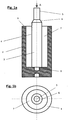
- the 1a and 1b show a sonotrode for an ultrasonic welding system for welding workpieces 20, 30.
- the sonotrode has a pressing element 2 having a contact surface 1, which can be applied to one of the workpieces 20 to be welded to one another in order to carry out the welding process with this contact surface 1 (cf. Fig. 2c ).
- the contact surface 1 is annular.
- a centering mandrel 3 projecting axially beyond the contact surface 1 is arranged on the pressing element 2 within the annular contact surface 1.
- the contact surface 1 has a closed ring shape.
- the centering mandrel 3 is arranged concentrically to the annular contact surface 1.
- the outer surface 4 of the centering mandrel 3 forms a cylindrical centering surface in the exemplary embodiment.
- the centering mandrel 3 also has a cylindrical centering tip 5 which is tapered relative to the centering surface 4.
- the centering tip 5 and the centering surface 4 are connected to one another by a conical transition section 6.
- the pressing element 2 has a cylindrical cavity 7, within which the centering mandrel 3 is arranged.
- the wall of the pressing element 2 forms the end face of the annular contact surface 1.
- the Fig. 1a it can also be seen that the centering pin 3 is screwed to the bottom of the pressing element 2. Accordingly, a thread 8 is provided within the cavity 7.
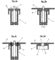
- connection element 20 is a plastic adapter designed as a holder for a (not shown) PDC sensor and the plastic component 30 is an external attachment part of a motor vehicle , for example a bumper made of injection molded plastic.
- the procedure is the same as in the Fig. 1a, b described sonotrode performed.
- the connecting element 20 having a recess 21 is first pushed onto the centering mandrel 3 and thereby centered relative to the sonotrode.
- the recess 21 is designed to fit the centering surface 4 of the centering mandrel 3.
- the tip of the centering mandrel 3 then passes through an opening 31 in the plastic component 30, the sonotrode being thereby centered relative to the plastic component 30. Accordingly, the opening 31 is designed to fit the cylindrical centering tip 5.
- the contact surface 1 of the sonotrode is brought into abutment on the side 22 of the connecting element 20 facing away from the plastic component 30.
- Fig. 2c the connecting element 20 is then welded to the plastic component 30 by means of the sonotrode, a circumferentially closed annular weld 9 being formed.
- the Fig. 2d shows the two workpieces 20, 30 welded together, that is to say the connecting element 20 on the one hand and the plastic component 30 on the other hand after removal of the sonotrode. Because of the welding process described with the centering mandrel 3, both parts 20, 30 are exactly centered on one another.
- the closed annular weld 9 is in Fig. 2d also recognizable.
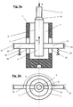
- the centering mandrel 3 is decoupled from the pressing element 2, that is to say not firmly connected to it.
- the pressing element 2 here has two recesses 10 on the circumference, which are spaced apart from the contact surface 1. These slot-shaped recesses 10, which are oriented in the axial direction x, are penetrated by a holder 11 oriented perpendicular to the centering mandrel 3, to which the centering mandrel 3 is fastened .
- the construction according to 3a, b is designed overall so that the holder 11 radially centers the centering mandrel 3 with respect to the pressing element 2.
- the Fig. 3a it can also be seen that the rod-shaped holder 11 is sprung in the axial direction x by means of spring elements 12 and is thus floating. In this way, height differences and an offset in the joining between the plastic component 30 and the connecting element 20 can be compensated. This ensures that the connection element 20 is always joined centrally to the opening 31 in the plastic component 30 without damaging the opening 31 or the plastic component 30.
- the holder is guided in the recesses 10 without play.
- lateral guide elements 13 are additionally provided for guiding the ends of the holder 11.
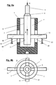
- the embodiment according to 4a, b differs from the embodiment in 3a, b in that the holder 11 is designed in the shape of a cross to ensure the radial centering of the centering mandrel 3 (see plan view in Fig. 4b ).
- the holder 11 is designed in the shape of a cross to ensure the radial centering of the centering mandrel 3 (see plan view in Fig. 4b ).
- four recesses 10 are provided in the pressing element 2, in which the cross-shaped holder 11 is guided without play in the axial direction x.
Description
Die Erfindung betrifft eine Sonotrode für eine Ultraschall-Schweißanlage mit den Merkmalen des Oberbegriffs des Patentanspruchs 1.The invention relates to a sonotrode for an ultrasonic welding system with the features of the preamble of
Eine Sonotrode zum Ultraschall-Schweißen ist beispielsweise aus der
Derartige Sonotroden werden beispielsweise zur Anbindung von sog. PDC-Sensoren (PDC = Park Distance Control) an Außenanbauteilen (z.B. Stoßfängern) von Kraftfahrzeugen eingesetzt. Die PDC-Sensoren dienen in der Regel als Einparkhilfen bzw. als Abstandswarner. Die PDC-Sensoren sind zumeist in mit dem Außenanbauteil verbundenen Adaptern montiert, um eine genaue Positionierung des Sensors am Außenanbauteil des Kraftfahrzeuges sicher zu stellen. Diese Adapter werden nun regelmäßig mit Ultraschall-Sonotroden von innen an die Außenanbauteile angeschweißt. Im Stand der Technik werden die Adapter für PDC-Sensoren beispielsweise mit zwei Stabsonotroden an das Außenanbauteil angeschweißt, wobei die verfahrenstechnische Anbindung der Adapter über zwei Schweißlappen erfolgt. Bei einer solchen Schweißanbindung ist jedoch die vorliegende Festigkeit durch eine physikalisch bedingte Abschälwirkung stark begrenzt. Mit Hilfe einer Ultraschall-Ringsonotrode kann nun eine in sich geschlossene Verschweißung erzielt werden, bei der eine deutlich reduzierte Abschälwirkung festzustellen ist und gleichzeitig eine vorteilhafte geringe Eindringtiefe der Schweißnoppen vorliegt. Durch die geringe Eindringtiefe wird auch das Schweißareal thermisch geringer belastet, was sich wiederum in einer Verringerung von Schweißabzeichnungen widerspiegelt.Such sonotrodes are used, for example, to connect so-called PDC sensors (PDC = Park Distance Control) to external attachments (for example bumpers) of motor vehicles. The PDC sensors are usually used as parking aids or as distance warnings. The PDC sensors are usually mounted in adapters connected to the external attachment in order to ensure precise positioning of the sensor on the external attachment of the motor vehicle. These adapters are now regularly welded to the external attachments from the inside using ultrasonic sonotrodes. In the prior art, the adapters for PDC sensors are welded to the external attachment, for example with two rod sonotrodes, the adapters being connected in terms of process technology using two welding tabs. With such a welded connection, however, the existing strength is severely limited by a physical peeling effect. With the help of an ultrasonic ring sonotrode, a self-contained welding can now be achieved, in which a significantly reduced peeling effect can be determined and at the same time there is an advantageously low penetration depth of the welding nubs. Due to the low penetration depth, too the welding area is thermally less stressed, which in turn is reflected in a reduction in welding marks.
Bei nicht durch das Außenanbauteil (z.B. den Kunststoff-Stoßfänger) durchtauchenden Adaptern ist eine Zentrierung des Adapters gegenüber dem Außenanbauteil notwendig. Dies wird gemäß dem Stand der Technik über eine separate Zentrieraufnahme gewährleistet. Eine solche Zentriereinrichtung ist bei einem Einsatz der oben erwähnten Stabsonotroden unproblematisch. Bei einer Ringsonotrode ist dies hingegen nicht der Fall, da die Zentriereinrichtung das Schwingverhalten der Ringsonotrode negativ beeinflussen kann. Um bei Ringsonotroden daher eine Entkopplung zwischen Sonotrode und Zentriereinrichtung zu erreichen, wird gemäß dem Stand der Technik die Ringsonotrode seitlich geöffnet. Über diese Öffnung wird die Zentrierung für den Adapter von außen angebunden und im Zentrum der ringförmigen Sonotrode gehalten. Eine geöffnete Ringsonotrode weist jedoch gegenüber einer geschlossenen Ringsonotrode eine schlechtere Verschweißung auf. Ferner ist das beschriebene Verfahren zur Sicherstellung der Zentrierung vergleichsweise aufwendig.In the case of adapters that do not pass through the external attachment (e.g. the plastic bumper), the adapter must be centered in relation to the external attachment. According to the state of the art, this is guaranteed by a separate centering fixture. Such a centering device is unproblematic when using the rod sonotrodes mentioned above. In the case of a ring sonotrode, however, this is not the case, since the centering device can have a negative influence on the vibration behavior of the ring sonotrode. In order to achieve decoupling between the sonotrode and the centering device in the case of ring sonotrodes, the ring sonotrode is opened laterally in accordance with the prior art. The centering for the adapter is connected from the outside via this opening and held in the center of the ring-shaped sonotrode. However, an open ring sonotrode has poorer welding than a closed ring sonotrode. Furthermore, the described method for ensuring the centering is comparatively complex.
Die
Der Erfindung liegt die Aufgabe zugrunde, eine Sonotrode mit den eingangs beschriebenen Merkmalen anzugeben, welche einerseits zuverlässig und auf einfache Weise eine exakte Zentrierung der zu verschweißenden Werkstücke zueinander ermöglicht und andererseits eine Verschweißung mit hoher Festigkeit gewährleistet.The invention is based on the object of specifying a sonotrode with the features described at the outset which, on the one hand, enables the workpieces to be welded to be centered precisely and reliably with respect to one another and on the other hand ensures high-strength welding.
Diese Aufgabe wird erfindungsgemäß durch die Merkmale im Kennzeichnungsteil des Patentanspruchs 1 gelöst. Vorzugsweise ist der Zentrierdorn an dem Andrückelement angeordnet, insbesondere befestigt. Mittels des erfindungsgemäßen Zentrierdornes im Zentrum der Sonotrode ist es möglich, beide miteinander zu verschweißenden Werkstücke gegenüber der Sonotrode zu zentrieren, woraus im Ergebnis auch beide Werkstücke zueinander exakt zentriert sind. Gemäß der erfindungsgemäßen Lehre kann daher auf die aufwendigen Verfahrensschritte bzw. Konstruktionen, welche im vorstehend beschriebenen Stand der Technik erforderlich sind, verzichtet werden. Gleichzeitig sind unter Anwendung der erfindungsgemäßen Sonotrode keine gestalterischen Einschränkungen hinsichtlich der Kontaktfläche in der Sonotrode vorhanden, wodurch eine optimale Verschweißung gewährleistet werden kann.This object is achieved by the features in the characterizing part of
Gemäß einer bevorzugten Ausführungsform der Erfindung weist die Kontaktfläche eine geschlossene Ringform auf. Aufgrund des Zentrierdorns im Zentrum der ringförmigen Kontaktfläche ist es nicht erforderlich, die umlaufende Kontaktfläche an einer Stelle zu öffnen, um hier einen Steg für eine Zentrierhalterung durchführen zu können. Stattdessen erfolgt die Zentrierung, wie bereits zuvor beschrieben, sowohl des ersten als auch des zweiten Werkstückpartners über den Zentrierdorn, so dass die beiden Werkstücke und die Ringsonotrode allesamt zueinander exakt zentriert sind. Zweckmäßigerweise ist daher der Zentrierdorn konzentrisch zur ringförmigen Kontaktfläche angeordnet.According to a preferred embodiment of the invention, the contact surface has a closed ring shape. Because of the centering mandrel in the center of the annular contact surface, it is not necessary to open the circumferential contact surface at one point in order to be able to carry out a web for a centering holder here. Instead, as already described, both the first and the second workpiece partner are centered via the centering mandrel, so that the two workpieces and the ring sonotrode are all exactly centered with respect to one another. The centering mandrel is therefore expediently arranged concentrically with the annular contact surface.
Die Mantelfläche des Zentrierdornes bildet eine, vorzugsweise zylindrische, Zentrierfläche. Auf diese Mantelfläche kann gemäß der erfindungsgemäßen Lehre das erste Werkstück aufgeschoben werden, wobei eine entsprechende Ausnehmung in diesem Werkstück den Zentrierdorn passgenau umfasst. Hierdurch ist dieses erste Werkstück gegenüber dem Zentrierdorn und damit gegenüber der Sonotrode zentriert. Erfindungsgemäß weist der Zentrierdorn zusätzlich eine gegenüber der Zentrierfläche verjüngte zylindrische Zentrierspitze auf. Auf dieser Zentrierspitze kann dann das zweite Werkstück, welches ebenfalls über eine entsprechende, passgenau zur Zentrierspitze gestaltete Öffnung verfügt, gegenüber dem Zentrierdorn und damit der Sonotrode zentriert werden. Im Rahmen der Erfindung liegt es ferner, dass bei einer verjüngten Zentrierspitze diese und die Zentrierfläche durch einen, vorzugsweise konischen, Übergangsabschnitt miteinander verbunden sind.The outer surface of the centering mandrel forms a, preferably cylindrical, centering surface. According to the teaching according to the invention, the first workpiece can be pushed onto this lateral surface, a corresponding recess in this workpiece encompassing the centering pin with a precise fit. As a result, this first workpiece is centered with respect to the centering mandrel and thus with respect to the sonotrode. According to the invention, the centering mandrel additionally has a cylindrical centering tip that is tapered relative to the centering surface. The second workpiece, which likewise has a corresponding opening that is designed to fit the centering point, can then be centered on this centering point with respect to the centering mandrel and thus the sonotrode. It is also within the scope of the invention that in the case of a tapered centering tip, this and the centering surface are connected to one another by a, preferably conical, transition section.
Gemäß einer bevorzugten Ausführungsform der Erfindung weist das Andrückelement eine zylinderförmige Kavität auf, innerhalb der der Zentrierdorn angeordnet ist. Hierbei bildet gemäß einer besonders bevorzugten Ausführungsform der Erfindung die Wandung des Andrückelementes stirnseitig die ringförmige Kontaktfläche. Grundsätzlich kann der Zentrierdorn bodenseitig mit dem Andrückelement verschraubt sein.According to a preferred embodiment of the invention, the pressing element has a cylindrical cavity, within which the centering mandrel is arranged. Here, according to a particularly preferred embodiment of the invention, the wall of the pressing element forms the end face of the annular contact surface. Basically, the centering mandrel can be screwed to the bottom of the pressure element.
Gegenstand der Erfindung ist ferner ein Verfahren zur Verschweißung eines Anschlusselementes, z.B. einer Halterung, insbesondere eines Adapters für einen PDC-Sensor, mit einem Bauteil, z.B. einem Kunststoffbauteil, insbesondere einem Außenanbauteil eines Kraftfahrzeuges, mittels der zuvor beschriebenen Sonotrode. Bei diesem erfindungsgemäßen Verfahren wird zunächst das eine Ausnehmung aufweisende Anschlusselement auf den Zentrierdorn aufgeschoben und hierdurch relativ zur Sonotrode zentriert. Vorzugsweise ist die Ausnehmung ist entsprechend passgenau zur Zentrierfläche des Zentrierdorns gestaltet. Danach durchfasst die Spitze des Zentrierdorns eine Öffnung im Bauteil, wodurch die Sonotrode relativ zum Bauteil zentriert wird. Zweckmäßigerweise ist entspechend die Öffnung im Bauteil passgenau zur Zentrierspitze gestaltet. Die Kontaktfläche der Sonotrode wird an der dem Bauteil abgewandten Seite des Anschlusselementes zur Anlage gebracht. Danach wird mittels der Sonotrode das Anschlusselement mit dem Bauteil verschweißt. Aufgrund der Zentrierung sowohl des Anschlusselementes als auch des Bauteiles gegenüber dem Zentrierdorn ist sichergestellt, dass Anschlusselement und Bauteil passgenau aufeinanderliegen und entsprechend miteinander verschweißt werden können.The invention further relates to a method for welding a connection element, for example a holder, in particular an adapter for a PDC sensor, to a component, for example a plastic component, in particular an external attachment part of a motor vehicle, by means of the sonotrode described above. In this invention First, the connection element having a recess is pushed onto the centering mandrel and thereby centered relative to the sonotrode. The recess is preferably designed to match the centering surface of the centering mandrel. The tip of the centering mandrel then passes through an opening in the component, as a result of which the sonotrode is centered relative to the component. The opening in the component is expediently designed to match the centering tip. The contact surface of the sonotrode is brought into contact on the side of the connecting element facing away from the component. The connecting element is then welded to the component using the sonotrode. The centering of both the connection element and the component relative to the centering mandrel ensures that the connection element and component lie precisely on top of one another and can be welded to one another accordingly.
Gemäß einer weiteren Ausführungsform der Erfindung ist der Zentrierdorn vom Andrückelement entkoppelt, also nicht mit diesem fest verbunden. Das Andrückelement weist in diesem Fall am Umfang mindestens eine Ausnehmung auf. Vorzugsweise ist diese Ausnehmung von der Kontaktfläche beabstandet, Dadurch kann auch bei dieser Ausführungsform die Kontaktfläche eine geschlossene Ringform aufweisen. Die mindestens eine Ausnehmung wird von einer Halterung durchfasst, an der der Zentrierdorn befestigt ist. Vorzugsweise ist die Halterung quer, insbesondere senkrecht zum Zentrierdorn ausgerichtet. Es können z.B. mindestens zwei Ausnehmungen vorgesehen sein, die zueinander fluchten, d.h. sie sind am Umfang des Andrückelementes um 180° zueinander versetzt angeordnet. Zweckmäßigerweise zentriert die Halterung den Zentrierdorn gegenüber dem Andrückelement radial. Hierzu kann beispielsweise die Halterung kreuzförmig ausgebildet sein und entsprechend vier Ausnehmungen im Andrückelement durchfassen, die jeweils am Umfang des Andrückelementes um 90° zueinander versetzt angeordnet sind.According to a further embodiment of the invention, the centering mandrel is decoupled from the pressing element, that is to say not firmly connected to it. In this case, the pressure element has at least one recess on the circumference. This recess is preferably spaced from the contact surface. As a result, the contact surface can also have a closed ring shape in this embodiment. The at least one recess is covered by a holder to which the centering pin is attached. The holder is preferably oriented transversely, in particular perpendicularly to the centering mandrel. For example, at least two recesses are provided which are aligned with one another, i.e. they are arranged offset from one another by 180 ° on the circumference of the pressing element. The holder expediently centers the centering mandrel radially with respect to the pressing element. For this purpose, the holder can, for example, be designed in a cross shape and correspondingly encompass four recesses in the pressing element, which are each offset from one another by 90 ° on the circumference of the pressing element.
Im Folgenden wird die Erfindung anhand einer lediglich ein Ausführungsbeispiel darstellenden Zeichnung ausführlich erläutert. Es zeigen schematisch:
- Fig. 1a
- eine erfindungsgemäße Sonotrode in einer Querschnittsdarstellung,
- Fig. 1b
- die Draufsicht A in
Fig. 1a , - Fig. 2a bis 2d
- ein erfindungsgemäßes Verfahren zum Verschweißen eines Anschlusselementes mit einem Kunststoffbauteil und
- Fig. 3a,b; 4a,b
- weitere Ausführungsformen der Erfindung in einer den
Fig. 1a,b entsprechenden Darstellung.
- Fig. 1a
- a sonotrode according to the invention in a cross-sectional view,
- Fig. 1b
- the top view A in
Fig. 1a , - 2a to 2d
- an inventive method for welding a connecting element with a plastic component and
- 3a, b; 4a, b
- further embodiments of the invention in a
Fig. 1a, b corresponding representation.
Die
Die
Gemäß
Gemäß
Gemäß
Bei der Ausführungsform gemäß den
Das Ausführungsbeispiel gemäß
Claims (9)
- Sonotrode for an ultrasonic welding system for welding workpieces (20, 30), having a pressing element (2) that has a contact surface (1), which pressing element (2) may be applied with this contact surface (1) to one of the workpieces (20) to be welded to one another for carrying out the welding process, wherein the contact surface (1) is ring-shaped in configuration, wherein a centering mandrel (3) projecting axially above the contact surface (1) is arranged within the ring-shaped contact surface (1) and wherein the circumferential surface (4) of the centering mandrel (3) forms a preferably cylindrical centering surface (4), characterized in that the centering mandrel (3) has a cylindrical centering tip (5) that is tapered with respect to the centering surface (4).
- Sonotrode according to claim 1, characterized in that the centering mandrel (3) is arranged, and preferably fixed, on the pressing element (2).
- Sonotrode according to claim 1 or 2, characterized in that the contact surface (1) has a closed ring shape.
- Sonotrode according to one of claims 1 to 3, characterized in that the centering mandrel (3) is arranged concentrically to the ring-shaped contact surface (1).
- Sonotrode according to one of claims 1 to 4, characterized in that the centering tip (5) and the centering surface (4) are connected to each other by a preferably conical transition section (6).
- Sonotrode according to one of claims 1 to 5, characterized in that the pressing element (2) has a, preferably cylinder-shaped, cavity (7) within which the centering mandrel (3) is arranged.
- Sonotrode according to claim 6, characterized in that the wall of the pressing element (2) forms the ring-shaped contact surface (1) on an end face thereof.
- Sonotrode according to one of claims 1 to 7, characterized in that the pressing element (2) comprises at least one recess (10) on the circumference, which is at a distance from the contact surface (1) and which is passed through by a holding device (11) that is fixed to the centering mandrel (3) and is preferably oriented transverse to the centering mandrel (3).
- Method for welding a connection element (20), in particular an adapter for a PDC sensor, to a component (30), in particular an external add-on component of a motor vehicle, by means of a sonotrode according to one of claims 1 to 8,- wherein the connection element (20) comprising a recess (21) is first pushed on to the centering mandrel (3) and is thus centered relative to the sonotrode,- wherein the tip of the centering mandrel (3) is then passed through an opening (31) in the component (30), thus centering the sonotrode relative to the component (30);- wherein the contact surface (1) of the sonotrode is brought into abutment against the side (22) of the connection element (20) remote from the component (30) and- wherein the connection element (20) is welded to the component (30) by means of the sonotrode.
Applications Claiming Priority (2)
| Application Number | Priority Date | Filing Date | Title |
|---|---|---|---|
| DE102015103799.8A DE102015103799A1 (en) | 2015-03-16 | 2015-03-16 | Sonotrode for an ultrasonic welding system and method for welding a connection element with a component |
| PCT/EP2016/000454 WO2016146252A1 (en) | 2015-03-16 | 2016-03-15 | Sonotrode for an ultrasound welding system and method for welding a connection element to a component |
Publications (3)
| Publication Number | Publication Date |
|---|---|
| EP3271136A1 EP3271136A1 (en) | 2018-01-24 |
| EP3271136B1 true EP3271136B1 (en) | 2020-04-29 |
| EP3271136B2 EP3271136B2 (en) | 2023-04-19 |
Family
ID=55538170
Family Applications (1)
| Application Number | Title | Priority Date | Filing Date |
|---|---|---|---|
| EP16710095.7A Active EP3271136B2 (en) | 2015-03-16 | 2016-03-15 | Sonotrode for an ultrasound welding system and method for welding a connection element to a component |
Country Status (7)
| Country | Link |
|---|---|
| US (1) | US10421237B2 (en) |
| EP (1) | EP3271136B2 (en) |
| DE (1) | DE102015103799A1 (en) |
| HU (1) | HUE050042T2 (en) |
| MX (1) | MX2017011757A (en) |
| WO (1) | WO2016146252A1 (en) |
| ZA (1) | ZA201705332B (en) |
Cited By (2)
| Publication number | Priority date | Publication date | Assignee | Title |
|---|---|---|---|---|
| CN110828322A (en) * | 2019-11-14 | 2020-02-21 | 安徽精实电子科技有限公司 | Method for improving straightness accuracy of PIN distance mold |
| DE102021121846A1 (en) | 2021-08-24 | 2023-03-02 | Rehau Automotive Se & Co. Kg | Method for assembling a connection element |
Families Citing this family (3)
| Publication number | Priority date | Publication date | Assignee | Title |
|---|---|---|---|---|
| DE102015103799A1 (en) | 2015-03-16 | 2016-09-22 | Rehau Ag + Co | Sonotrode for an ultrasonic welding system and method for welding a connection element with a component |
| DE102018124779A1 (en) * | 2018-10-08 | 2020-04-09 | Ensinger Gmbh | Process for producing an insulating profile |
| US20220226942A1 (en) * | 2021-01-15 | 2022-07-21 | T.A. Systems, Inc. | Bracket presenter for ultrasonic welder |
Citations (16)
| Publication number | Priority date | Publication date | Assignee | Title |
|---|---|---|---|---|
| DE2442219B2 (en) | 1974-09-04 | 1981-06-04 | Moskovskij stankoinstrumental'nyj institut, Moskva | Device for centering components |
| DE8702983U1 (en) | 1987-02-26 | 1988-06-23 | Siemens Ag, 1000 Berlin Und 8000 Muenchen, De | |
| DE69014605T2 (en) | 1990-04-04 | 1995-07-06 | Toppan Printing Co Ltd | Filling and sealing device. |
| WO1998001239A1 (en) | 1996-07-05 | 1998-01-15 | Minnesota Mining And Manufacturing Company | Rotary acoustic horn |
| US6309490B1 (en) | 2000-05-10 | 2001-10-30 | Branson Ultrasonics Corporation | Air actuated ultrasonic tool |
| DE19828914C2 (en) | 1998-06-18 | 2001-11-15 | Hielscher Gmbh | Ultrasonic screening device |
| DE10101415C1 (en) | 2001-01-13 | 2002-07-25 | Ford Global Tech Inc | Automatic welding method for securing threaded nut to apertured plate uses point welding device with stationary and movable electrodes |
| DE10209492A1 (en) | 2002-03-05 | 2003-10-09 | Daimler Chrysler Ag | Pressure welding machine for welding a nut to a metal sheet comprises a floating centering pin having a metal sheet-receiving region adjacent to a nut-receiving region for centering the metal sheet |
| DE102005036908A1 (en) | 2005-08-05 | 2007-02-08 | Audi Ag | Fixing unit for installation of a window pane in a vehicle bodywork opening, for adhesive bonding, has a fixing pin with relative movements against the pane to give it a positive fit |
| DE102006006344A1 (en) | 2006-02-08 | 2007-08-16 | Sumitomo Electric Bordnetze Gmbh | Ultrasonic welding device comprises a workpiece holder that acts as a mechanical vibratory system to support bond formation during welding |
| DE102009019644A1 (en) | 2009-04-30 | 2010-11-04 | Maschinenfabrik Spaichingen Gmbh | Device for executing e.g. punching operation, at plastic parts of motor vehicle, has workpiece retainer designed as demountable workpiece retainer, where different workpieces are processed on workpiece retainer in base unit |
| DE102010000968A1 (en) | 2010-01-18 | 2011-07-21 | FRIMO Group GmbH, 49504 | Sonotrode for ultrasonic welding machine, comprises ultrasonic generator, which guides high-frequency electrical energy to converter, converts electrical energy into mechanical vibrations and guides to the sonotrode via booster |
| EP2769830A1 (en) | 2013-02-20 | 2014-08-27 | MS Spaichingen GmbH | Round sonotrode |
| EP2873512A1 (en) | 2013-11-15 | 2015-05-20 | MS Spaichingen GmbH | Method and device for stamping and connecting plastic pieces |
| DE102014212313A1 (en) | 2014-06-26 | 2015-12-31 | Telsonic Holding Ag | Torsion sonotrode, apparatus and method for ultrasonic welding |
| DE102015103799A1 (en) | 2015-03-16 | 2016-09-22 | Rehau Ag + Co | Sonotrode for an ultrasonic welding system and method for welding a connection element with a component |
Family Cites Families (1)
| Publication number | Priority date | Publication date | Assignee | Title |
|---|---|---|---|---|
| DE3907783A1 (en) * | 1989-03-10 | 1990-09-20 | Basf Ag | Apparatus for bonding moulded parts by ultrasound |
-
2015
- 2015-03-16 DE DE102015103799.8A patent/DE102015103799A1/en active Pending
-
2016
- 2016-03-15 EP EP16710095.7A patent/EP3271136B2/en active Active
- 2016-03-15 MX MX2017011757A patent/MX2017011757A/en unknown
- 2016-03-15 HU HUE16710095A patent/HUE050042T2/en unknown
- 2016-03-15 US US15/555,536 patent/US10421237B2/en active Active
- 2016-03-15 WO PCT/EP2016/000454 patent/WO2016146252A1/en active Application Filing
-
2017
- 2017-08-07 ZA ZA2017/05332A patent/ZA201705332B/en unknown
Patent Citations (16)
| Publication number | Priority date | Publication date | Assignee | Title |
|---|---|---|---|---|
| DE2442219B2 (en) | 1974-09-04 | 1981-06-04 | Moskovskij stankoinstrumental'nyj institut, Moskva | Device for centering components |
| DE8702983U1 (en) | 1987-02-26 | 1988-06-23 | Siemens Ag, 1000 Berlin Und 8000 Muenchen, De | |
| DE69014605T2 (en) | 1990-04-04 | 1995-07-06 | Toppan Printing Co Ltd | Filling and sealing device. |
| WO1998001239A1 (en) | 1996-07-05 | 1998-01-15 | Minnesota Mining And Manufacturing Company | Rotary acoustic horn |
| DE19828914C2 (en) | 1998-06-18 | 2001-11-15 | Hielscher Gmbh | Ultrasonic screening device |
| US6309490B1 (en) | 2000-05-10 | 2001-10-30 | Branson Ultrasonics Corporation | Air actuated ultrasonic tool |
| DE10101415C1 (en) | 2001-01-13 | 2002-07-25 | Ford Global Tech Inc | Automatic welding method for securing threaded nut to apertured plate uses point welding device with stationary and movable electrodes |
| DE10209492A1 (en) | 2002-03-05 | 2003-10-09 | Daimler Chrysler Ag | Pressure welding machine for welding a nut to a metal sheet comprises a floating centering pin having a metal sheet-receiving region adjacent to a nut-receiving region for centering the metal sheet |
| DE102005036908A1 (en) | 2005-08-05 | 2007-02-08 | Audi Ag | Fixing unit for installation of a window pane in a vehicle bodywork opening, for adhesive bonding, has a fixing pin with relative movements against the pane to give it a positive fit |
| DE102006006344A1 (en) | 2006-02-08 | 2007-08-16 | Sumitomo Electric Bordnetze Gmbh | Ultrasonic welding device comprises a workpiece holder that acts as a mechanical vibratory system to support bond formation during welding |
| DE102009019644A1 (en) | 2009-04-30 | 2010-11-04 | Maschinenfabrik Spaichingen Gmbh | Device for executing e.g. punching operation, at plastic parts of motor vehicle, has workpiece retainer designed as demountable workpiece retainer, where different workpieces are processed on workpiece retainer in base unit |
| DE102010000968A1 (en) | 2010-01-18 | 2011-07-21 | FRIMO Group GmbH, 49504 | Sonotrode for ultrasonic welding machine, comprises ultrasonic generator, which guides high-frequency electrical energy to converter, converts electrical energy into mechanical vibrations and guides to the sonotrode via booster |
| EP2769830A1 (en) | 2013-02-20 | 2014-08-27 | MS Spaichingen GmbH | Round sonotrode |
| EP2873512A1 (en) | 2013-11-15 | 2015-05-20 | MS Spaichingen GmbH | Method and device for stamping and connecting plastic pieces |
| DE102014212313A1 (en) | 2014-06-26 | 2015-12-31 | Telsonic Holding Ag | Torsion sonotrode, apparatus and method for ultrasonic welding |
| DE102015103799A1 (en) | 2015-03-16 | 2016-09-22 | Rehau Ag + Co | Sonotrode for an ultrasonic welding system and method for welding a connection element with a component |
Non-Patent Citations (7)
| Title |
|---|
| ANONYMOUS: "Aufnahme- und Auflagebolzen DIN 6321 Auszug", GANTER NORM, October 2002 (2002-10-01), pages 1, XP055979461, Retrieved from the Internet <URL:https://www.ganternorm.com/de/produkte/schnell-suche/DIN-6321-Aufnahme-Auflagebolzen?q=6321> |
| ANONYMOUS: "Aufnahmebolzen und Positionierstifte günstiger als selbstgemacht", KONSTRUKTIONSPRAXIS, 2 February 2012 (2012-02-02), pages 1 - 2, XP055979403 |
| ANONYMOUS: "Das Magazin", SONOTRONIC ULTRASONICS TECHNOLOGY, January 2014 (2014-01-01), Düsseldorf, pages 1 - 36, XP055979380 |
| ANONYMOUS: "Keramik erhöht die Standzeit von Zentrier- und Positionierstiften im Karosseriebau", KONSTRUKTIONSPRAXIS, 28 July 2008 (2008-07-28), pages 1 - 4, XP055979396, Retrieved from the Internet <URL:https://www.konstruktionspraxis.vogel.de/keramik-erhoeht-die-standzeit-von-zentrier-und- positionierstiften-im-karosseriebau-a-140455> |
| ANONYMOUS: "SAC-Kupplungs- Werkzeug-Satz Operating Instructions SAC Clutch Alignment Tool Set 2306", BETRIEBSANLEITUNG SAC-KUPPLUNGS- WERKZEUG-SATZ, August 2011 (2011-08-01), pages 1 - 12, XP055979417 |
| ANONYMOUS: "Spezialwerkzeuge", SCHAEFFLER AUTOMOTIVE AFTERMARKET, December 2014 (2014-12-01), pages 1 - 21, XP055979422 |
| ANONYMOUS: "Verpackungstechnik - Ultraschall-Systeme Zum Siegeln, Schweißen, Schneiden Und Stanzen", SONOTRONIC ULTRASONICS TECHNOLOGY, November 2014 (2014-11-01), pages 1 - 8, XP055979388 |
Cited By (3)
| Publication number | Priority date | Publication date | Assignee | Title |
|---|---|---|---|---|
| CN110828322A (en) * | 2019-11-14 | 2020-02-21 | 安徽精实电子科技有限公司 | Method for improving straightness accuracy of PIN distance mold |
| CN110828322B (en) * | 2019-11-14 | 2021-03-23 | 安徽精实电子科技有限公司 | Method for improving straightness accuracy of PIN distance mold |
| DE102021121846A1 (en) | 2021-08-24 | 2023-03-02 | Rehau Automotive Se & Co. Kg | Method for assembling a connection element |
Also Published As
| Publication number | Publication date |
|---|---|
| EP3271136A1 (en) | 2018-01-24 |
| WO2016146252A1 (en) | 2016-09-22 |
| US10421237B2 (en) | 2019-09-24 |
| EP3271136B2 (en) | 2023-04-19 |
| US20180043625A1 (en) | 2018-02-15 |
| DE102015103799A1 (en) | 2016-09-22 |
| MX2017011757A (en) | 2017-12-04 |
| ZA201705332B (en) | 2019-06-26 |
| HUE050042T2 (en) | 2020-11-30 |
Similar Documents
| Publication | Publication Date | Title |
|---|---|---|
| EP3271136B1 (en) | Sonotrode for an ultrasound welding system and method for welding a connection element to a component | |
| EP2475475B1 (en) | Method for loosely pre-fixing at least two components to be rigidly connected to each other | |
| DE4426785C1 (en) | Motor vehicle body with integrated structural transverse strut | |
| EP2739434B1 (en) | Method for connecting two components, and component connection | |
| DE2537146A1 (en) | DEVICE FOR POSITIONING TWO COMPONENTS | |
| DE102014103796A1 (en) | System for elastically averaged alignment | |
| DE102014105908B4 (en) | Tool for machining a workpiece and method for producing a tool | |
| EP2420433B1 (en) | Method and fixing assembly for correct fixing of a device to a structural section of a motor vehicle | |
| EP2769830B2 (en) | Round sonotrode | |
| DE102016105354A1 (en) | Machining tool | |
| EP2636911A1 (en) | Mounting assembly | |
| DE3706123C2 (en) | ||
| EP1503114B1 (en) | Piston-piston rod assembly | |
| DE102015207176A1 (en) | Method for producing a chassis component | |
| DE102014212313B4 (en) | Torsion sonotrode, device and method for welding by means of ultrasound | |
| DE102012110257B4 (en) | Drive cable with ultrasonically welded end cap and method for producing such a drive cable | |
| DE102016221144B3 (en) | Method for connecting at least two components | |
| EP3275597B1 (en) | Tool and method for tightening and loosening components | |
| DE202017104190U1 (en) | Ultrasonic processing device and radial-resonant ultrasonic sonotrode | |
| DE60004917T2 (en) | Device for attaching at least two handle parts of a kitchen container and kitchen container with such a device | |
| DE19734539C2 (en) | Component connection | |
| WO2002101229A1 (en) | Fuel injection valve for internal combustion engines | |
| EP3966057B1 (en) | Assembly mount in a vehicle | |
| DE102021121846A1 (en) | Method for assembling a connection element | |
| DE102022109417A1 (en) | Fastening device for a dragonfly body |
Legal Events
| Date | Code | Title | Description |
|---|---|---|---|
| STAA | Information on the status of an ep patent application or granted ep patent |
Free format text: STATUS: THE INTERNATIONAL PUBLICATION HAS BEEN MADE |
|
| PUAI | Public reference made under article 153(3) epc to a published international application that has entered the european phase |
Free format text: ORIGINAL CODE: 0009012 |
|
| STAA | Information on the status of an ep patent application or granted ep patent |
Free format text: STATUS: REQUEST FOR EXAMINATION WAS MADE |
|
| 17P | Request for examination filed |
Effective date: 20170807 |
|
| AK | Designated contracting states |
Kind code of ref document: A1 Designated state(s): AL AT BE BG CH CY CZ DE DK EE ES FI FR GB GR HR HU IE IS IT LI LT LU LV MC MK MT NL NO PL PT RO RS SE SI SK SM TR |
|
| AX | Request for extension of the european patent |
Extension state: BA ME |
|
| DAV | Request for validation of the european patent (deleted) | ||
| DAX | Request for extension of the european patent (deleted) | ||
| GRAP | Despatch of communication of intention to grant a patent |
Free format text: ORIGINAL CODE: EPIDOSNIGR1 |
|
| STAA | Information on the status of an ep patent application or granted ep patent |
Free format text: STATUS: GRANT OF PATENT IS INTENDED |
|
| RIC1 | Information provided on ipc code assigned before grant |
Ipc: B29C 65/78 20060101ALI20191030BHEP Ipc: B29C 65/08 20060101AFI20191030BHEP |
|
| INTG | Intention to grant announced |
Effective date: 20191122 |
|
| GRAS | Grant fee paid |
Free format text: ORIGINAL CODE: EPIDOSNIGR3 |
|
| GRAA | (expected) grant |
Free format text: ORIGINAL CODE: 0009210 |
|
| STAA | Information on the status of an ep patent application or granted ep patent |
Free format text: STATUS: THE PATENT HAS BEEN GRANTED |
|
| AK | Designated contracting states |
Kind code of ref document: B1 Designated state(s): AL AT BE BG CH CY CZ DE DK EE ES FI FR GB GR HR HU IE IS IT LI LT LU LV MC MK MT NL NO PL PT RO RS SE SI SK SM TR |
|
| REG | Reference to a national code |
Ref country code: GB Ref legal event code: FG4D Free format text: NOT ENGLISH |
|
| REG | Reference to a national code |
Ref country code: CH Ref legal event code: EP |
|
| REG | Reference to a national code |
Ref country code: AT Ref legal event code: REF Ref document number: 1262644 Country of ref document: AT Kind code of ref document: T Effective date: 20200515 |
|
| REG | Reference to a national code |
Ref country code: DE Ref legal event code: R096 Ref document number: 502016009751 Country of ref document: DE |
|
| REG | Reference to a national code |
Ref country code: IE Ref legal event code: FG4D Free format text: LANGUAGE OF EP DOCUMENT: GERMAN |
|
| REG | Reference to a national code |
Ref country code: NL Ref legal event code: MP Effective date: 20200429 |
|
| REG | Reference to a national code |
Ref country code: LT Ref legal event code: MG4D |
|
| PG25 | Lapsed in a contracting state [announced via postgrant information from national office to epo] |
Ref country code: LT Free format text: LAPSE BECAUSE OF FAILURE TO SUBMIT A TRANSLATION OF THE DESCRIPTION OR TO PAY THE FEE WITHIN THE PRESCRIBED TIME-LIMIT Effective date: 20200429 Ref country code: PT Free format text: LAPSE BECAUSE OF FAILURE TO SUBMIT A TRANSLATION OF THE DESCRIPTION OR TO PAY THE FEE WITHIN THE PRESCRIBED TIME-LIMIT Effective date: 20200831 Ref country code: GR Free format text: LAPSE BECAUSE OF FAILURE TO SUBMIT A TRANSLATION OF THE DESCRIPTION OR TO PAY THE FEE WITHIN THE PRESCRIBED TIME-LIMIT Effective date: 20200730 Ref country code: FI Free format text: LAPSE BECAUSE OF FAILURE TO SUBMIT A TRANSLATION OF THE DESCRIPTION OR TO PAY THE FEE WITHIN THE PRESCRIBED TIME-LIMIT Effective date: 20200429 Ref country code: NO Free format text: LAPSE BECAUSE OF FAILURE TO SUBMIT A TRANSLATION OF THE DESCRIPTION OR TO PAY THE FEE WITHIN THE PRESCRIBED TIME-LIMIT Effective date: 20200729 Ref country code: SE Free format text: LAPSE BECAUSE OF FAILURE TO SUBMIT A TRANSLATION OF THE DESCRIPTION OR TO PAY THE FEE WITHIN THE PRESCRIBED TIME-LIMIT Effective date: 20200429 Ref country code: IS Free format text: LAPSE BECAUSE OF FAILURE TO SUBMIT A TRANSLATION OF THE DESCRIPTION OR TO PAY THE FEE WITHIN THE PRESCRIBED TIME-LIMIT Effective date: 20200829 |
|
| RAP2 | Party data changed (patent owner data changed or rights of a patent transferred) |
Owner name: REHAU AG + CO |
|
| PG25 | Lapsed in a contracting state [announced via postgrant information from national office to epo] |
Ref country code: LV Free format text: LAPSE BECAUSE OF FAILURE TO SUBMIT A TRANSLATION OF THE DESCRIPTION OR TO PAY THE FEE WITHIN THE PRESCRIBED TIME-LIMIT Effective date: 20200429 Ref country code: RS Free format text: LAPSE BECAUSE OF FAILURE TO SUBMIT A TRANSLATION OF THE DESCRIPTION OR TO PAY THE FEE WITHIN THE PRESCRIBED TIME-LIMIT Effective date: 20200429 Ref country code: HR Free format text: LAPSE BECAUSE OF FAILURE TO SUBMIT A TRANSLATION OF THE DESCRIPTION OR TO PAY THE FEE WITHIN THE PRESCRIBED TIME-LIMIT Effective date: 20200429 Ref country code: BG Free format text: LAPSE BECAUSE OF FAILURE TO SUBMIT A TRANSLATION OF THE DESCRIPTION OR TO PAY THE FEE WITHIN THE PRESCRIBED TIME-LIMIT Effective date: 20200729 |
|
| REG | Reference to a national code |
Ref country code: HU Ref legal event code: AG4A Ref document number: E050042 Country of ref document: HU |
|
| PG25 | Lapsed in a contracting state [announced via postgrant information from national office to epo] |
Ref country code: AL Free format text: LAPSE BECAUSE OF FAILURE TO SUBMIT A TRANSLATION OF THE DESCRIPTION OR TO PAY THE FEE WITHIN THE PRESCRIBED TIME-LIMIT Effective date: 20200429 Ref country code: NL Free format text: LAPSE BECAUSE OF FAILURE TO SUBMIT A TRANSLATION OF THE DESCRIPTION OR TO PAY THE FEE WITHIN THE PRESCRIBED TIME-LIMIT Effective date: 20200429 |
|
| REG | Reference to a national code |
Ref country code: DE Ref legal event code: R026 Ref document number: 502016009751 Country of ref document: DE |
|
| PG25 | Lapsed in a contracting state [announced via postgrant information from national office to epo] |
Ref country code: ES Free format text: LAPSE BECAUSE OF FAILURE TO SUBMIT A TRANSLATION OF THE DESCRIPTION OR TO PAY THE FEE WITHIN THE PRESCRIBED TIME-LIMIT Effective date: 20200429 Ref country code: RO Free format text: LAPSE BECAUSE OF FAILURE TO SUBMIT A TRANSLATION OF THE DESCRIPTION OR TO PAY THE FEE WITHIN THE PRESCRIBED TIME-LIMIT Effective date: 20200429 Ref country code: DK Free format text: LAPSE BECAUSE OF FAILURE TO SUBMIT A TRANSLATION OF THE DESCRIPTION OR TO PAY THE FEE WITHIN THE PRESCRIBED TIME-LIMIT Effective date: 20200429 Ref country code: SM Free format text: LAPSE BECAUSE OF FAILURE TO SUBMIT A TRANSLATION OF THE DESCRIPTION OR TO PAY THE FEE WITHIN THE PRESCRIBED TIME-LIMIT Effective date: 20200429 Ref country code: EE Free format text: LAPSE BECAUSE OF FAILURE TO SUBMIT A TRANSLATION OF THE DESCRIPTION OR TO PAY THE FEE WITHIN THE PRESCRIBED TIME-LIMIT Effective date: 20200429 |
|
| PLBI | Opposition filed |
Free format text: ORIGINAL CODE: 0009260 |
|
| PLAX | Notice of opposition and request to file observation + time limit sent |
Free format text: ORIGINAL CODE: EPIDOSNOBS2 |
|
| PG25 | Lapsed in a contracting state [announced via postgrant information from national office to epo] |
Ref country code: SK Free format text: LAPSE BECAUSE OF FAILURE TO SUBMIT A TRANSLATION OF THE DESCRIPTION OR TO PAY THE FEE WITHIN THE PRESCRIBED TIME-LIMIT Effective date: 20200429 Ref country code: PL Free format text: LAPSE BECAUSE OF FAILURE TO SUBMIT A TRANSLATION OF THE DESCRIPTION OR TO PAY THE FEE WITHIN THE PRESCRIBED TIME-LIMIT Effective date: 20200429 |
|
| 26 | Opposition filed |
Opponent name: TELSONIC HOLDING AG Effective date: 20210129 Opponent name: SONOTRONIC NAGEL GMBH Effective date: 20210128 |
|
| PG25 | Lapsed in a contracting state [announced via postgrant information from national office to epo] |
Ref country code: SI Free format text: LAPSE BECAUSE OF FAILURE TO SUBMIT A TRANSLATION OF THE DESCRIPTION OR TO PAY THE FEE WITHIN THE PRESCRIBED TIME-LIMIT Effective date: 20200429 |
|
| PLBB | Reply of patent proprietor to notice(s) of opposition received |
Free format text: ORIGINAL CODE: EPIDOSNOBS3 |
|
| PG25 | Lapsed in a contracting state [announced via postgrant information from national office to epo] |
Ref country code: MC Free format text: LAPSE BECAUSE OF FAILURE TO SUBMIT A TRANSLATION OF THE DESCRIPTION OR TO PAY THE FEE WITHIN THE PRESCRIBED TIME-LIMIT Effective date: 20200429 |
|
| REG | Reference to a national code |
Ref country code: CH Ref legal event code: PL |
|
| GBPC | Gb: european patent ceased through non-payment of renewal fee |
Effective date: 20210315 |
|
| REG | Reference to a national code |
Ref country code: BE Ref legal event code: MM Effective date: 20210331 |
|
| PG25 | Lapsed in a contracting state [announced via postgrant information from national office to epo] |
Ref country code: IE Free format text: LAPSE BECAUSE OF NON-PAYMENT OF DUE FEES Effective date: 20210315 Ref country code: GB Free format text: LAPSE BECAUSE OF NON-PAYMENT OF DUE FEES Effective date: 20210315 Ref country code: LU Free format text: LAPSE BECAUSE OF NON-PAYMENT OF DUE FEES Effective date: 20210315 Ref country code: LI Free format text: LAPSE BECAUSE OF NON-PAYMENT OF DUE FEES Effective date: 20210331 Ref country code: CH Free format text: LAPSE BECAUSE OF NON-PAYMENT OF DUE FEES Effective date: 20210331 |
|
| REG | Reference to a national code |
Ref country code: DE Ref legal event code: R081 Ref document number: 502016009751 Country of ref document: DE Owner name: REHAU AUTOMOTIVE SE & CO. KG, DE Free format text: FORMER OWNER: REHAU AG + CO, 95111 REHAU, DE |
|
| RAP4 | Party data changed (patent owner data changed or rights of a patent transferred) |
Owner name: REHAU AUTOMOTIVE SE & CO. KG |
|
| REG | Reference to a national code |
Ref country code: HU Ref legal event code: GB9C Owner name: REHAU AUTOMOTIVE SE & CO.KG, DE Free format text: FORMER OWNER(S): REHAU AG + CO, DE |
|
| REG | Reference to a national code |
Ref country code: AT Ref legal event code: HC Ref document number: 1262644 Country of ref document: AT Kind code of ref document: T Owner name: REHAU AUTOMOTIVE SE & CO. KG, DE Effective date: 20220530 |
|
| PG25 | Lapsed in a contracting state [announced via postgrant information from national office to epo] |
Ref country code: BE Free format text: LAPSE BECAUSE OF NON-PAYMENT OF DUE FEES Effective date: 20210331 |
|
| RAP4 | Party data changed (patent owner data changed or rights of a patent transferred) |
Owner name: REHAU INDUSTRIES SE & CO. KG |
|
| RAP4 | Party data changed (patent owner data changed or rights of a patent transferred) |
Owner name: REHAU AUTOMOTIVE SE & CO. KG |
|
| REG | Reference to a national code |
Ref country code: CH Ref legal event code: PK Free format text: BERICHTIGUNGEN |
|
| RIC2 | Information provided on ipc code assigned after grant |
Ipc: B29C 43/18 20060101ALI20220928BHEP Ipc: B29C 43/02 20060101AFI20220928BHEP |
|
| REG | Reference to a national code |
Ref country code: FR Ref legal event code: PLFP Year of fee payment: 8 |
|
| PUAH | Patent maintained in amended form |
Free format text: ORIGINAL CODE: 0009272 |
|
| STAA | Information on the status of an ep patent application or granted ep patent |
Free format text: STATUS: PATENT MAINTAINED AS AMENDED |
|
| 27A | Patent maintained in amended form |
Effective date: 20230419 |
|
| AK | Designated contracting states |
Kind code of ref document: B2 Designated state(s): AL AT BE BG CH CY CZ DE DK EE ES FI FR GB GR HR HU IE IS IT LI LT LU LV MC MK MT NL NO PL PT RO RS SE SI SK SM TR |
|
| REG | Reference to a national code |
Ref country code: DE Ref legal event code: R102 Ref document number: 502016009751 Country of ref document: DE |
|
| PGFP | Annual fee paid to national office [announced via postgrant information from national office to epo] |
Ref country code: FR Payment date: 20230313 Year of fee payment: 8 Ref country code: CZ Payment date: 20230222 Year of fee payment: 8 Ref country code: AT Payment date: 20230302 Year of fee payment: 8 |
|
| REG | Reference to a national code |
Ref country code: HU Ref legal event code: HC9C Owner name: REHAU AUTOMOTIVE SE & CO.KG, DE Free format text: FORMER OWNER(S): REHAU AG + CO, DE; REHAU AUTOMOTIVE SE & CO.KG, DE |
|
| PGFP | Annual fee paid to national office [announced via postgrant information from national office to epo] |
Ref country code: IT Payment date: 20230330 Year of fee payment: 8 Ref country code: HU Payment date: 20230310 Year of fee payment: 8 Ref country code: DE Payment date: 20230331 Year of fee payment: 8 |
|
| PG25 | Lapsed in a contracting state [announced via postgrant information from national office to epo] |
Ref country code: CY Free format text: LAPSE BECAUSE OF FAILURE TO SUBMIT A TRANSLATION OF THE DESCRIPTION OR TO PAY THE FEE WITHIN THE PRESCRIBED TIME-LIMIT Effective date: 20200429 |