EP3270789B1 - System zur unterstützung der positionierung eines intraoralen dentalen radiologiesensors - Google Patents
System zur unterstützung der positionierung eines intraoralen dentalen radiologiesensors Download PDFInfo
- Publication number
- EP3270789B1 EP3270789B1 EP16706644.8A EP16706644A EP3270789B1 EP 3270789 B1 EP3270789 B1 EP 3270789B1 EP 16706644 A EP16706644 A EP 16706644A EP 3270789 B1 EP3270789 B1 EP 3270789B1
- Authority
- EP
- European Patent Office
- Prior art keywords
- sensor
- face
- mirror
- support
- imaging assembly
- Prior art date
- Legal status (The legal status is an assumption and is not a legal conclusion. Google has not performed a legal analysis and makes no representation as to the accuracy of the status listed.)
- Active
Links
Images

Classifications
-
- A—HUMAN NECESSITIES
- A61—MEDICAL OR VETERINARY SCIENCE; HYGIENE
- A61B—DIAGNOSIS; SURGERY; IDENTIFICATION
- A61B6/00—Apparatus or devices for radiation diagnosis; Apparatus or devices for radiation diagnosis combined with radiation therapy equipment
- A61B6/50—Apparatus or devices for radiation diagnosis; Apparatus or devices for radiation diagnosis combined with radiation therapy equipment specially adapted for specific body parts; specially adapted for specific clinical applications
- A61B6/51—Apparatus or devices for radiation diagnosis; Apparatus or devices for radiation diagnosis combined with radiation therapy equipment specially adapted for specific body parts; specially adapted for specific clinical applications for dentistry
- A61B6/512—Intraoral means
-
- A—HUMAN NECESSITIES
- A61—MEDICAL OR VETERINARY SCIENCE; HYGIENE
- A61B—DIAGNOSIS; SURGERY; IDENTIFICATION
- A61B34/00—Computer-aided surgery; Manipulators or robots specially adapted for use in surgery
- A61B34/20—Surgical navigation systems; Devices for tracking or guiding surgical instruments, e.g. for frameless stereotaxis
-
- A—HUMAN NECESSITIES
- A61—MEDICAL OR VETERINARY SCIENCE; HYGIENE
- A61B—DIAGNOSIS; SURGERY; IDENTIFICATION
- A61B6/00—Apparatus or devices for radiation diagnosis; Apparatus or devices for radiation diagnosis combined with radiation therapy equipment
- A61B6/42—Arrangements for detecting radiation specially adapted for radiation diagnosis
- A61B6/4208—Arrangements for detecting radiation specially adapted for radiation diagnosis characterised by using a particular type of detector
-
- A—HUMAN NECESSITIES
- A61—MEDICAL OR VETERINARY SCIENCE; HYGIENE
- A61B—DIAGNOSIS; SURGERY; IDENTIFICATION
- A61B6/00—Apparatus or devices for radiation diagnosis; Apparatus or devices for radiation diagnosis combined with radiation therapy equipment
- A61B6/58—Testing, adjusting or calibrating thereof
- A61B6/589—Setting distance between source unit and patient
-
- A—HUMAN NECESSITIES
- A61—MEDICAL OR VETERINARY SCIENCE; HYGIENE
- A61B—DIAGNOSIS; SURGERY; IDENTIFICATION
- A61B6/00—Apparatus or devices for radiation diagnosis; Apparatus or devices for radiation diagnosis combined with radiation therapy equipment
- A61B6/44—Constructional features of apparatus for radiation diagnosis
- A61B6/4429—Constructional features of apparatus for radiation diagnosis related to the mounting of source units and detector units
- A61B6/4452—Constructional features of apparatus for radiation diagnosis related to the mounting of source units and detector units the source unit and the detector unit being able to move relative to each other
-
- A—HUMAN NECESSITIES
- A61—MEDICAL OR VETERINARY SCIENCE; HYGIENE
- A61B—DIAGNOSIS; SURGERY; IDENTIFICATION
- A61B6/00—Apparatus or devices for radiation diagnosis; Apparatus or devices for radiation diagnosis combined with radiation therapy equipment
- A61B6/46—Arrangements for interfacing with the operator or the patient
-
- A—HUMAN NECESSITIES
- A61—MEDICAL OR VETERINARY SCIENCE; HYGIENE
- A61B—DIAGNOSIS; SURGERY; IDENTIFICATION
- A61B6/00—Apparatus or devices for radiation diagnosis; Apparatus or devices for radiation diagnosis combined with radiation therapy equipment
- A61B6/58—Testing, adjusting or calibrating thereof
- A61B6/588—Setting distance between source unit and detector unit
Definitions
- the invention relates to medical imaging and more particularly to intra-oral dental radiology.
- Dental X-ray systems use an image sensor that is placed in the patient's mouth, behind and near the dental region to be observed.
- An X-ray source is placed outside the patient's mouth, facing the sensor and exposing it to a short X-ray flash, through biological tissue or other material to be observed that is located between the source and the active face of the sensor.
- the active face of the sensor is the face that is sensitive to radiation, and that provides the radio picture of the anatomical area that is desired to observe.
- the practitioner may have difficulty in correctly positioning the active face of the sensor relative to the anatomical part of the patient he wants to X-ray (teeth, roots %) and visually check, directly, and correct if necessary, this positioning.
- the verification will be done indirectly, on the shot obtained: if the positioning is not good, the shot obtained will be of no use to the practitioner, who will have to take a new x-ray.
- the document US4012638 discloses an image pickup assembly comprising an intraoral image sensor with infrared reflectors.
- Supporting accessories are available to practitioners to facilitate the correct placement of the image sensor as well as keeping in the right position the time to perform the X-ray.
- Some of these support accessories are specially designed to make specific shots. These are for example accessories comprising a sensor support zone and a bite area.
- These support accessories allow all types of shots. These accessories generally comprise a sensor support zone at the end of a guide and holding rod which facilitates manipulation by the practitioner.
- An object of the invention is thus to assist in the positioning of the intraoral oral sensor.
- the invention proposes a radiological image-taking assembly comprising an intra-oral radiological image sensor, the sensor comprising an active face and a rear face, the active face being intended to be turned towards an X-ray source.
- this assembly comprises at least one mirror which is placed in front of the active face of the sensor, the mirror forming a face reflecting visible light which is turned on the same side as the active face of the sensor.
- a mirror is formed on an outer face of an encapsulation box enclosing the sensor, wherein the outer face corresponds to the active face of the sensor.
- the mirror may have been previously formed on the front cover of the housing, before encapsulation and welding of the cover with a case back shell.
- the image pickup assembly may comprise at least one accessory supporting or containing the sensor where an external face of the accessory is placed in front of the active face of the sensor and turned in the same direction as the active face. sensor, and a mirror formed on this outer face of the accessory.
- the accessory may be a tool comprising a support zone secured to a rod, where the support zone is provided to hold the sensor, the active face of the sensor against the inner face of the support zone.
- the mirror can then be formed on an outer face of the support zone.
- the accessory may be a hygienic protective envelope, disposable or not, designed to enclose an intraoral sensor.
- the mirror can then be formed on the outer surface of the envelope.
- the accessory may be a flexible comfort shell inside which the sensor is placed, active face against a bottom wall of the shell and a mirror is formed on the outer face of this wall.
- the imaging assembly may comprise one or more of these accessories, and at least the (outermost) face of the imaging assembly, which is that of one of the accessories, comprises a mirror according to the invention.
- the mirror may be formed by layer deposition of a reflective material, by evaporation under vacuum, on a casing front cover before encapsulation, and / or on the front face of the encapsulating box enclosing the sensor and / or on the outer face of the comfort shell and / or the support area of an accessory.
- the mirror may also be formed by a mirror part cut from a strip of material having a reflective face and integrally molded in a thermoplastic material.
- the mirror can be further formed by cutting and gluing a mirror piece into a strip of material having a reflective face and another adhesive face.
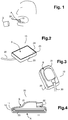
- an intraoral oral radiological sensor 10 is placed in the mouth of a patient, its active face A behind the anatomical zone to be radiographed.
- An external X-ray source is placed outside the mouth, in alignment with the area to be radiographed and the active face A of the sensor.
- the senor includes an output cable 30 for connection to a computer.
- the cable will allow the transmission image and other possible interface or control signals and its power supply or the charging of a battery integrated in the sensor. But a wireless interface is possible.
- the assembly comprising a scintillator, an electronic circuit that performs the image capture and transmission of the image, and a protective housing in which this circuit is encapsulated.
- the electronic circuit can be in any state-of-the-art technology (CCD, MOS).
- CCD state-of-the-art technology
- the assembly comprising the electronic circuit 11 and the scintillator 12 is placed (possibly with other elements not shown such as stiffening elements, discrete components, a battery ...) in a shell 21 whose bottom forms the back side B ( figure 3 ) of the housing, with an opening 22 provided to allow the passage of an electrical output cable 30.
- a front face cover 23 ( figure 2 ) is reported over the circuit and assembled to the shell, typically by ultrasonic welding.
- the front face cover 23 corresponds to the active face A of the sensor: under this cover 23 we will thus find the scintillator 12, and under the scintillator, the matrix of photosensitive elements of the electronic circuit 11. X radiation emitted by a source placed in front of this active face, are transformed by the scintillator into light photons detectable by the photosensitive elements of the matrix.
- the shell 21 and the front cover 23 which form the housing 20 are designed to provide the necessary rigidity to protect the electronic circuit and especially the photosensitive matrix, to allow a sealed output of the output cable 30 and to also provide a comfort in the mouth for the patient.
- the case of rectangular shape may have cut corners and rounded edges; the front cover can be made of hard plastic material; the edges of the case can be made of soft plastic with smooth rubber appearance.
- the invention proposes to place at least one mirror in front of the active face of the sensor, with the reflecting surface of the mirror facing in the same direction as the active face A , that is to say to the area to be radiographed and to the external source of X-rays ( Figure 1 ).
- the radiological imaging unit (or part of it, including of course the image sensor) is placed in the patient's mouth, behind the anatomical area to be radiographed: on the surface of this mirror, illuminated by the visible light (natural, or more effectively the light emitted by a lighting device facing the patient's mouth), will thus form an image of the anatomical area behind which the sensor is placed: the practitioner will be able to help with this image, to adjust the positioning of the sensor relative to the area it wants to X-ray.
- the mirror will be as transparent as possible to X-rays so as not to affect the quality of the radiological image.
- a positioning aid mirror according to the invention is integrated in the sensor itself, as illustrated in FIG. figure 5 a mirror M1 is formed on the external front face of the encapsulation box 20 of the sensor corresponding to the active face A of the sensor: that is to say, taking again the example of a case illustrated on the Figures 2 to 4 , on the cover 23 of the front face of this housing, over the entire surface of this cover with the exception of the edge 24.
- the surface of the mirror M1 is substantially equal and exactly positioned, in superposition, in the axis of the X-ray source at the photosensitive matrix surface of the sensor: the visible image that forms on the mirror is close to the radiographic image that will be obtained, and the practitioner can accurately position the sensor by observing this image.
- the mirror M1 can be formed before or after encapsulation of the sensor in its housing 20. If it is made after encapsulation, a technique of depositing a reflective material by vapor evaporation can be used, with a masking tool to delimit the zone of depositing and depositing the reflective material everywhere on the internal face of the cover 23, with the exception of the edge 24.
- the mirror before encapsulation More specifically, it is possible to provide the mirror M1 at the time of manufacture of the cover 23 of the front face, before encapsulation of the circuit and assembly to the hull 21 of the rear face.
- the same technique of deposition by evaporation can be used.
- the mirror piece is then integrated into the hood on the surface of this hood.
- the mirror piece P could be used as the bottom of the cover and form the edge 24 by overmolding thermoplastic material.
- the mirror piece P It is also possible to report the mirror piece P on the front cover of the case by gluing. Preferably it is then possible to provide the mirror piece P with an adhesive side, using a pressure-sensitive adhesive, which is protected by a peelable film. The mirror can then be placed by the practitioner on the sensor, that is to say on the front face of the encapsulation box.
- Imaging sets used by practitioners may also include one or more accessories in addition to the sensor.
- accessories designed to assist in the manipulation and placement of the sensor in the patient's mouth, hygiene accessories, or accessories designed to improve patient comfort: whatever accessory or accessories are used a mirror will preferably be formed on the outer surface of the imaging assembly, i.e., the one in the foreground viewed from the side of the practitioner looking inwardly of the mouth of the patient, whether it is a face of the sensor housing or that of an accessory that is placed in the mouth between the area to be radiographed and the active face of the sensor.
- These accessories are made of materials suitable for medical or dental use (for single use or not) and transparent to X-radiation, and in particular plastic materials, which are generally not transparent to visible light, and for which reason, can mask or make less visible (for the practitioner), at least in part, the active face of the sensor.
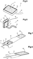
- a first accessory may be a sensor support element 40 ( "handler” ) as shown in FIG. figure 6 .
- the sensor support element comprises a sensor support 41, designed to place and hold a sensor 10, and a rod 42 integral with the support area 41, which the practitioner will be able to handle.
- the rod may or may not be articulated. It can also be coupled to other elements (not shown), such as for example an alignment window of the X-ray source, or a bite element.
- the support 41 has an outer face A ', rod side and an inner face provided to receive the sensor, active face A of the sensor 10 against this inner face and to hold the sensor in this position: for this purpose the inner face may include mechanical elements not shown, such as slides or clamps for example, or this inner face is an adhesive face, with a pressure sensitive type adhesive (PSA) ....
- PSA pressure sensitive type adhesive
- the support 41 is presented, as illustrated on the figure 6 , as a substantially flat surface which partially masks at least the active face A of the sensor. In the example shown, the surface is full. But it could include one or more openings.
- a mirror M2 may be provided on the outer face A 'of the support 41, reflecting face turned on the same side as the active face A of the sensor, that is to say towards the area to be radiographed. If, as shown, the sensor comprises a mirror M1 on its active face A, the two mirrors M1 and M2 are oriented on the same side, that is to say to face the external source of X-rays ( Figure 1 ).
- the mirror M2 can be made on the face A 'of the support 41 using the same techniques indicated supra: evaporation under vacuum; or, when at least the support 41 is made by molding a thermoplastic material, surface integration of this support by precutting a mirror part and molding over and around this piece of the support form ( or support element 40); or else, gluing a mirror piece P.
- the dimensions of the mirror M2 will advantageously be able to match the dimensions of the photosensitive matrix of the sensor.
- the mirror M2 formed on the support 41 allows the most accurate positioning of the sensor, because the image that will form on this mirror will correspond as closely to the radiological image that the sensor can detect. In this situation, the sensor housing does not need to be coated with a mirror. It is the same if the support 41 is larger than the sensor.
- the dimensions of the mirror made on the outer face A 'of the sensor support will depend in practice on the surface of this support. In all cases we will seek to promote the accuracy of positioning: that is to say, it will seek to match the best size of the mirror with the size of the radiological image that can detect the sensor. For example, if the support is sufficiently large, the mirror will preferably be sized to correspond to sensors of average dimensions: that is to say, neither the smallest nor the largest. In this way we will not lose too much precision at the ends of the range.
- the size of the support corresponds to the size of the smaller sensors, or is smaller, it will be provided that the mirror M2 completely covers the surface of the support, in order to offer the practitioner the image as close as possible to that provided by the sensor.
- the sensor is also coated with a mirror as shown in FIG. figure 6 .
- a second accessory may be a hygienic envelope 50, generally for single use, as shown on the Figures 7 and 8 .
- a hygienic envelope 50 is used by the practitioner to improve the rules of cleanliness and hygiene.
- the envelope comprises an opening through which the sensor is introduced ( Figure 7 ) and pushed to the bottom of the envelope. After the radiological image is taken, the imaging unit is removed from the patient's mouth, the sensor is removed from the envelope and the envelope is sterilized, or discarded (single-use envelope).
- the hygienic envelope is made of a plastic material suitable for medical and dental use, transparent to radiation and can be transparent to visible light. But even if it is indeed transparent to visible light, this transparency is not optimal because its surface is not very reflective and supposing that the sensor which it encloses comprises a mirror M1 according to the invention, on the active face of the sensor, the image formed on this mirror M1 will not be clear.
- the sensor must then be introduced with its active face A on the same side as the mirror M3 on the face A of the envelope If, as shown, the sensor comprises a mirror M1 on its active face A, the two mirrors M1 and M2 are then oriented on the same side, so that once placed in the mouth of the patient the two will be oriented in the same direction, behind the anatomical area to be radiographed and facing the external source of X-rays ( Figure 1 ). It is then the mirror M3 which is on the external face of the image-taking assembly thus formed, which will enable the practitioner to control and adjust the positioning of the sensor in the patient's mouth, by observing the visible image that is formed on this mirror.
- This mirror M3 will for example be formed by a vacuum evaporation technique, or by bonding a mirror part P as detailed above.
- the mirror M3 will be made on an outer face of this envelope so as to cover a surface equivalent to the active face of the sensor, that is, the inside surface of the front cover, with the exception of the border 24.
- the mirror will preferably be sized to correspond to sensors of average dimensions: that is to say, neither the smallest nor the most great. In this way we will not lose too much precision at the ends of the range.
- the imaging unit may comprise both a support accessory such as element 40 of the figure 6 , a hygienic envelope 50 and a sensor 10.
- a support accessory such as element 40 of the figure 6
- a hygienic envelope 50 and a sensor 10.
- it can have a support member 40, on which we will position, by means of an adhesive provided on the internal face of the support 41, the portion A "to the right of the active face A of the sensor contained in an envelope.
- the assembly is removed from the patient's mouth, the sensor is extracted from the envelope and the support element and / or the envelope may be discarded or sterilized for a new use.
- the image pickup assembly thus constituted, that is to say the support member 40 with its support 41 on which the sensor 10 enclosed in an envelope 50, is placed, comprises at least one mirror (M2) on the outer face of the support 41: this mirror which is on the outer face of this image pickup assembly, will allow the practitioner to control and adjust the positioning of the sensor, by direct observation of the image that forms on it.
- M2 mirror
- the senor and / or the envelope of this set may also comprise a respective mirror (M1, M3) according to the invention.
- comfort shell 60 is a flexible comfort shell 60 as schematically illustrated on the Figures 9 and 10 .
- These comfort shells are for example made of a flexible plastic material with a smooth rubber appearance. They make contact with the sensor more pleasant (when this sensor is in the mouth) and at the same time they dampen the effects of tightening or possible shocks between or against the teeth of the patient.
- the practitioner uses the comfort shell as follows: he places the sensor 10 inside the shell, active face A of the sensor 10 pressed against the bottom wall 61 of the shell 60.
- a mirror M4 may be provided on the outer face A '"of the shell wall 61, oriented on the same side as the active face A of the sensor, behind the anatomical zone to be radiographed and facing the external source of X-rays .
- the mirror M4 goes allow the practitioner to control and adjust the positioning of the sensor in the patient's mouth, by observing the visible image that is formed on the mirror.
- the sensor 10 does not need to be coated with a mirror, but it can be.
- the two mirrors M1 and M4 are oriented on the same side towards the area to be radiographed.
- the invention applies to an image pickup assembly which may comprise a single sensor, or a sensor in combination with one or a plurality of accessories supporting or containing the sensor.
- an image pickup assembly which may comprise a single sensor, or a sensor in combination with one or a plurality of accessories supporting or containing the sensor.
- at least the outer face of this assembly is coated with a mirror, such as, when the imaging assembly (or part of this assembly including the sensor) is placed in the mouth behind the area to X-ray, the reflecting face of this mirror is placed behind the area to be radiographed and in front of the active face A of the sensor.
- this mirror is the mirror M1 made on the active face of the sensor.
- the image acquisition assembly consists of a combination of a sensor with at least one accessory: at least one mirror is made on the outer face of the accessory which will be just behind the area to be radiographed; and the sensor and / or the other accessory or accessories may each be or not coated with a mirror.
- this assembly comprises at least one mirror M2 on the outer face of the support zone of the shell.
- the comfort shell 60 is also coated with a mirror such as M4, especially if the size of the support 41 is smaller than the shell.
- the reflecting face of this mirror M4 will be oriented like that of the mirror M2 and as the active face of the sensor, that is to say toward the area to be radiographed.
- the sensor housing is coated with a mirror.
- the practitioner will be offered a set comprising both a sensor whose case comprises a mirror reflecting face on the side of its active face, one or more support elements whose front face of support comprises a reflecting mirror face, and envelopes having a reflective portion.
- a sensor whose case comprises a mirror reflecting face on the side of its active face
- one or more support elements whose front face of support comprises a reflecting mirror face
- envelopes having a reflective portion In this way, whatever how to use the elements of the set, it is ensured that there will always be a mirror face in the immediate vicinity of the area to be radiographed.
- the mirror or mirrors will be formed from a material transparent to X radiation and compatible for medical or dental use, and which offers good adhesion quality to plastic materials and especially thermoplastic materials generally used for hulls, cases, support element, and plastic materials used to make the hygienic envelopes.
- the mirror or mirrors will for example be formed from a metallic material such as aluminum, chromium or nickel, for example, using standard deposition technologies, in particular vacuum evaporation, allowing thin layer deposition. of homogeneous thickness, so that the integration of the mirror (s) into the image-taking assembly does not degrade or non-significantly the quality of the radiological image obtained.
Landscapes
- Health & Medical Sciences (AREA)
- Life Sciences & Earth Sciences (AREA)
- Engineering & Computer Science (AREA)
- Medical Informatics (AREA)
- Surgery (AREA)
- Veterinary Medicine (AREA)
- Public Health (AREA)
- Molecular Biology (AREA)
- Nuclear Medicine, Radiotherapy & Molecular Imaging (AREA)
- General Health & Medical Sciences (AREA)
- Animal Behavior & Ethology (AREA)
- Biomedical Technology (AREA)
- Heart & Thoracic Surgery (AREA)
- High Energy & Nuclear Physics (AREA)
- Radiology & Medical Imaging (AREA)
- Pathology (AREA)
- Optics & Photonics (AREA)
- Physics & Mathematics (AREA)
- Biophysics (AREA)
- Dentistry (AREA)
- Oral & Maxillofacial Surgery (AREA)
- Robotics (AREA)
- Apparatus For Radiation Diagnosis (AREA)
Claims (10)
- Baugruppe zur radiologischen Bildaufnahme, beinhaltend einen intraoralen Bildsensor (10), welcher eine aktive Seite (A) beinhaltet, welche der lichtempfindlichen Oberfläche entspricht, welche dazu bestimmt ist, in Richtung einer Röntgenstrahlenquelle gedreht zu werden, dadurch gekennzeichnet, dass sie mindestens einen Spiegel (M1) beinhaltet, der vor der aktiven Seite des Sensors platziert wird, wobei die das sichtbare Licht reflektierende Spiegelseite in dieselbe Richtung wie die aktive Seite des Sensors gedreht wird.
- Baugruppe zur Bildaufnahme nach Anspruch 1, bei welcher ein Spiegel (M1) auf einem Schutzgehäuse (20) gebildet ist, welcher den Sensor umschließt.
- Baugruppe zur Bildaufnahme nach Anspruch 2, bei welcher ein Spiegel (M1) auf einer Haube (23) der Vorderseite des Schutzgehäuses gebildet ist, vor Verkapseln und Verschweißen der Haube mit einer Schale (21) der Hinterseite des Gehäuses.
- Baugruppe zur Bildaufnahme nach einem der Ansprüche 1 bis 3, beinhaltend mindestens ein Zubehörteil, welches den Sensor stützt oder diesen enthält und wobei eine äußere Seite des Zubehörteils vor der aktiven Seite des Sensors platziert ist und in dieselbe Richtung gedreht ist wie die aktive Seite des Sensors, dadurch gekennzeichnet, dass ein Spiegel an der äußeren Seite des Zubehörteils gebildet ist.
- Baugruppe zur Bildaufnahme nach Anspruch 4, dadurch gekennzeichnet, dass das Zubehörteil eine Stütze (41) beinhaltet, die fest mit einem Stab (42) verbunden ist, wobei die Stütze eine Vorderseite (A') aufweist, welche im Wesentlichen eben ist, welche einer Hinterseite gegenüberliegt, wobei der Sensor auf der Stütze platziert ist, mit der aktiven Seite (A) gegen die Rückseite der Stütze, und ein Spiegel (M2) auf der Vorderseite (A') der Stütze gebildet ist.
- Baugruppe zur Bildaufnahme nach Anspruch 4, dadurch gekennzeichnet, dass das Zubehörteil eine hygiensche Schutzhülle (50) ist, welche den Sensor (10) einschließt, und die Hülle einen Spiegel (M3) beinhaltet, welcher auf einer äußeren Seite der Hülle gebildet ist, wobei der Sensor im Innern der Hülle platziert ist, wobei seine aktive Seite (A) zur selben Seite wie die äußere Seite (A') der Hülle ausgerichtet ist und er unter dem Spiegel (M3) der Hülle platziert ist.
- Baugruppe zur Bildaufnahme nach Anspruch 4, dadurch gekennzeichnet, dass das Zubehörteil eine flexible Komfortschale (60) ist, in deren Innern der Sensor platziert ist, mit der aktitven Seite gegen eine Bodenwand (61) der Schale, und ein Spiegel (M4) an einer externen Seite dieser Wand (61) gebildet ist.
- Baugruppe zur Bildaufnahme nach Anspruch 2, 3, 4, 5 oder 7, bei welcher der Spiegel ein Teil (P) ist, welches aus einem Materialstreifen ausgeschnitten ist, welcher eine reflektierende Seite besitzt, welche durch Formen an der Oberfläche eines thermoplastischen Materials integriert ist.
- Baugruppe zur Bildaufnahme nach einem der Ansprüche 1 bis 7, bei welcher der Spiegel durch Ablagern eines reflektierenden Materials durch Verdampfen in Vakuum gebildet wird.
- Baugruppe zur Bildaufnahme nach einem der Ansprüche 1 bis 7, bei welcher der Spiegel ein Teil (P) ist, welches aus einem Materialstreifen ausgeschnitten ist, welcher eine reflektierende Seite und eine andere selbsklebende Seite besitzt.
Applications Claiming Priority (2)
| Application Number | Priority Date | Filing Date | Title |
|---|---|---|---|
| FR1552344A FR3033690B1 (fr) | 2015-03-20 | 2015-03-20 | Systeme d'aide au positionnement d'un capteur radiologique dentaire intra-oral |
| PCT/EP2016/054142 WO2016150654A1 (fr) | 2015-03-20 | 2016-02-26 | Systeme d'aide au positionnement d'un capteur radiologique dentaire intra-oral |
Publications (2)
| Publication Number | Publication Date |
|---|---|
| EP3270789A1 EP3270789A1 (de) | 2018-01-24 |
| EP3270789B1 true EP3270789B1 (de) | 2018-12-26 |
Family
ID=53541733
Family Applications (1)
| Application Number | Title | Priority Date | Filing Date |
|---|---|---|---|
| EP16706644.8A Active EP3270789B1 (de) | 2015-03-20 | 2016-02-26 | System zur unterstützung der positionierung eines intraoralen dentalen radiologiesensors |
Country Status (4)
| Country | Link |
|---|---|
| US (1) | US20180064406A1 (de) |
| EP (1) | EP3270789B1 (de) |
| FR (1) | FR3033690B1 (de) |
| WO (1) | WO2016150654A1 (de) |
Families Citing this family (3)
| Publication number | Priority date | Publication date | Assignee | Title |
|---|---|---|---|---|
| FI20187045A1 (en) | 2018-03-16 | 2019-09-17 | Athlos Oy | Wireless intraoral X-ray imaging sensor |
| FI129522B (en) * | 2018-08-08 | 2022-03-31 | Athlos Oy | Wireless intraoral sensor holder |
| US12138094B2 (en) * | 2022-12-09 | 2024-11-12 | Janet Thole Simpson | Dental x-ray receptor holding device |
Family Cites Families (10)
| Publication number | Priority date | Publication date | Assignee | Title |
|---|---|---|---|---|
| US3631598A (en) * | 1970-05-18 | 1972-01-04 | Maurice G Lussier | Dental instrument |
| US4012638A (en) * | 1976-03-09 | 1977-03-15 | Altschuler Bruce R | Dental X-ray alignment system |
| US4727416A (en) * | 1987-03-05 | 1988-02-23 | Fuji Optical Systems, Inc. | Electronic video dental camera |
| US6142777A (en) * | 1999-04-09 | 2000-11-07 | Pulpdent Corporation | Disposable dental mirror |
| US20060274890A1 (en) * | 2005-02-23 | 2006-12-07 | Razzano Michael R | Image capture device and methods |
| US20070287123A1 (en) * | 2006-06-12 | 2007-12-13 | Swift Ronald L | Mouth mirror handle featuring improved lens mounting technique |
| US7535990B2 (en) * | 2006-12-22 | 2009-05-19 | The Boeing Company | Low profile vision system for remote x-ray inspection |
| US7517148B2 (en) * | 2007-03-28 | 2009-04-14 | Ceisel Robert J | Dental device having a sensor film holder with tooth clamp |
| US8308360B1 (en) * | 2009-07-31 | 2012-11-13 | Irina Goral | Dry powder-coated dental X-ray film and associated method |
| US8222610B2 (en) * | 2009-09-02 | 2012-07-17 | Sirona Dental Systems Gmbh | Auxiliary component for medical device having additional functionality |
-
2015
- 2015-03-20 FR FR1552344A patent/FR3033690B1/fr not_active Expired - Fee Related
-
2016
- 2016-02-26 US US15/559,786 patent/US20180064406A1/en not_active Abandoned
- 2016-02-26 WO PCT/EP2016/054142 patent/WO2016150654A1/fr not_active Ceased
- 2016-02-26 EP EP16706644.8A patent/EP3270789B1/de active Active
Non-Patent Citations (1)
| Title |
|---|
| None * |
Also Published As
| Publication number | Publication date |
|---|---|
| FR3033690A1 (fr) | 2016-09-23 |
| WO2016150654A1 (fr) | 2016-09-29 |
| US20180064406A1 (en) | 2018-03-08 |
| FR3033690B1 (fr) | 2017-03-10 |
| EP3270789A1 (de) | 2018-01-24 |
Similar Documents
| Publication | Publication Date | Title |
|---|---|---|
| EP2136710B1 (de) | Bildsensor für zahnröntgen mit flexibler überspritzung | |
| EP3270789A1 (de) | System zur unterstützung der positionierung eines intraoralen dentalen radiologiesensors | |
| EP3119466B1 (de) | Kit zum halten und schutz von in einem körperbereich eines patienten positionierten kathetern | |
| JPH0410596Y2 (de) | ||
| FR2931055A1 (fr) | Capteur radiologique dentaire a structure minimisant l'encombrement | |
| EP4727424A1 (de) | Abstandhalter aus flexiblem material für zahnärztliche aufnahmen | |
| BE1024704B1 (fr) | Dispositif medical pour stomie | |
| EP3629994B1 (de) | Kieferorthopädische vorrichtung und verfahren zur herstellung einer solchen vorrichtung | |
| FR2721204A1 (fr) | Anneau convexe pour stomies invaginées. | |
| EP2924483B1 (de) | Verschlussmembran umfassender verbindungsstecker | |
| JP7651532B2 (ja) | イメージングプレート保護アセンブリ及びイメージングプレートアセンブリ | |
| FR3140530A1 (fr) | Dispositif de mesure d’oxymétrie | |
| FR2490952A1 (fr) | Poche d'incontinence | |
| FR2912897A1 (fr) | Viseur pour l'aide a l'implantation d'une broche ou analogue dans un os | |
| FR3138026A1 (fr) | Espaceur pour acquisition de vue d’une bouche d’un utilisateur comportant des ailettes élastiquement déformables | |
| FR2462152A1 (fr) | Sac pour application post-operatoire, notamment pour le recueil d'excretions corporelles | |
| WO1992018088A1 (fr) | Bouteille pourvue d'une tetine d'alimentation | |
| EP4661732A1 (de) | Verfahren zur bestimmung, ob der betriebskanal eines medizinischen endoskops eingesetzt wurde | |
| FR2522837A1 (en) | X-ray sensitive film for dental use - is covered and includes screen to produce blank identification strip | |
| FR2997006A1 (fr) | Accessoire pour capteur numerique dentaire | |
| EP4661731A1 (de) | Medizinisches endoskop mit schleuse | |
| WO2014096101A1 (fr) | Equipement comprenant au moins un module actif à alimentation électrique et destiné à être porté par la tête d'un individu | |
| FR2462730A3 (fr) | Cadre pour visionner une bande de film comportant plusieurs images | |
| FR2762690A1 (fr) | Cassette porte-film pour radiographie multiple et son procede d'utilisation | |
| FR3075180A1 (fr) | Cassette radiologique numerique portable |
Legal Events
| Date | Code | Title | Description |
|---|---|---|---|
| STAA | Information on the status of an ep patent application or granted ep patent |
Free format text: STATUS: THE INTERNATIONAL PUBLICATION HAS BEEN MADE |
|
| PUAI | Public reference made under article 153(3) epc to a published international application that has entered the european phase |
Free format text: ORIGINAL CODE: 0009012 |
|
| STAA | Information on the status of an ep patent application or granted ep patent |
Free format text: STATUS: REQUEST FOR EXAMINATION WAS MADE |
|
| 17P | Request for examination filed |
Effective date: 20170919 |
|
| AK | Designated contracting states |
Kind code of ref document: A1 Designated state(s): AL AT BE BG CH CY CZ DE DK EE ES FI FR GB GR HR HU IE IS IT LI LT LU LV MC MK MT NL NO PL PT RO RS SE SI SK SM TR |
|
| AX | Request for extension of the european patent |
Extension state: BA ME |
|
| RIN1 | Information on inventor provided before grant (corrected) |
Inventor name: PASCAL, NATHALIE Inventor name: JULIEN, FLORIAN |
|
| RIN1 | Information on inventor provided before grant (corrected) |
Inventor name: JULIEN, FLORIAN Inventor name: PASCAL, NATHALIE |
|
| DAV | Request for validation of the european patent (deleted) | ||
| DAX | Request for extension of the european patent (deleted) | ||
| GRAP | Despatch of communication of intention to grant a patent |
Free format text: ORIGINAL CODE: EPIDOSNIGR1 |
|
| STAA | Information on the status of an ep patent application or granted ep patent |
Free format text: STATUS: GRANT OF PATENT IS INTENDED |
|
| INTG | Intention to grant announced |
Effective date: 20180802 |
|
| GRAS | Grant fee paid |
Free format text: ORIGINAL CODE: EPIDOSNIGR3 |
|
| GRAA | (expected) grant |
Free format text: ORIGINAL CODE: 0009210 |
|
| STAA | Information on the status of an ep patent application or granted ep patent |
Free format text: STATUS: THE PATENT HAS BEEN GRANTED |
|
| AK | Designated contracting states |
Kind code of ref document: B1 Designated state(s): AL AT BE BG CH CY CZ DE DK EE ES FI FR GB GR HR HU IE IS IT LI LT LU LV MC MK MT NL NO PL PT RO RS SE SI SK SM TR |
|
| RAP1 | Party data changed (applicant data changed or rights of an application transferred) |
Owner name: TELEDYNE E2V SEMICONDUCTORS SAS |
|
| REG | Reference to a national code |
Ref country code: GB Ref legal event code: FG4D Free format text: NOT ENGLISH |
|
| REG | Reference to a national code |
Ref country code: CH Ref legal event code: EP |
|
| REG | Reference to a national code |
Ref country code: AT Ref legal event code: REF Ref document number: 1080302 Country of ref document: AT Kind code of ref document: T Effective date: 20190115 |
|
| REG | Reference to a national code |
Ref country code: DE Ref legal event code: R096 Ref document number: 602016008714 Country of ref document: DE |
|
| REG | Reference to a national code |
Ref country code: IE Ref legal event code: FG4D Free format text: LANGUAGE OF EP DOCUMENT: FRENCH |
|
| PG25 | Lapsed in a contracting state [announced via postgrant information from national office to epo] |
Ref country code: BG Free format text: LAPSE BECAUSE OF FAILURE TO SUBMIT A TRANSLATION OF THE DESCRIPTION OR TO PAY THE FEE WITHIN THE PRESCRIBED TIME-LIMIT Effective date: 20190326 Ref country code: LT Free format text: LAPSE BECAUSE OF FAILURE TO SUBMIT A TRANSLATION OF THE DESCRIPTION OR TO PAY THE FEE WITHIN THE PRESCRIBED TIME-LIMIT Effective date: 20181226 Ref country code: NO Free format text: LAPSE BECAUSE OF FAILURE TO SUBMIT A TRANSLATION OF THE DESCRIPTION OR TO PAY THE FEE WITHIN THE PRESCRIBED TIME-LIMIT Effective date: 20190326 Ref country code: HR Free format text: LAPSE BECAUSE OF FAILURE TO SUBMIT A TRANSLATION OF THE DESCRIPTION OR TO PAY THE FEE WITHIN THE PRESCRIBED TIME-LIMIT Effective date: 20181226 Ref country code: LV Free format text: LAPSE BECAUSE OF FAILURE TO SUBMIT A TRANSLATION OF THE DESCRIPTION OR TO PAY THE FEE WITHIN THE PRESCRIBED TIME-LIMIT Effective date: 20181226 |
|
| REG | Reference to a national code |
Ref country code: NL Ref legal event code: MP Effective date: 20181226 |
|
| REG | Reference to a national code |
Ref country code: LT Ref legal event code: MG4D |
|
| PG25 | Lapsed in a contracting state [announced via postgrant information from national office to epo] |
Ref country code: AL Free format text: LAPSE BECAUSE OF FAILURE TO SUBMIT A TRANSLATION OF THE DESCRIPTION OR TO PAY THE FEE WITHIN THE PRESCRIBED TIME-LIMIT Effective date: 20181226 Ref country code: SE Free format text: LAPSE BECAUSE OF FAILURE TO SUBMIT A TRANSLATION OF THE DESCRIPTION OR TO PAY THE FEE WITHIN THE PRESCRIBED TIME-LIMIT Effective date: 20181226 Ref country code: RS Free format text: LAPSE BECAUSE OF FAILURE TO SUBMIT A TRANSLATION OF THE DESCRIPTION OR TO PAY THE FEE WITHIN THE PRESCRIBED TIME-LIMIT Effective date: 20181226 Ref country code: GR Free format text: LAPSE BECAUSE OF FAILURE TO SUBMIT A TRANSLATION OF THE DESCRIPTION OR TO PAY THE FEE WITHIN THE PRESCRIBED TIME-LIMIT Effective date: 20190327 |
|
| REG | Reference to a national code |
Ref country code: AT Ref legal event code: MK05 Ref document number: 1080302 Country of ref document: AT Kind code of ref document: T Effective date: 20181226 |
|
| PG25 | Lapsed in a contracting state [announced via postgrant information from national office to epo] |
Ref country code: NL Free format text: LAPSE BECAUSE OF FAILURE TO SUBMIT A TRANSLATION OF THE DESCRIPTION OR TO PAY THE FEE WITHIN THE PRESCRIBED TIME-LIMIT Effective date: 20181226 |
|
| PG25 | Lapsed in a contracting state [announced via postgrant information from national office to epo] |
Ref country code: PL Free format text: LAPSE BECAUSE OF FAILURE TO SUBMIT A TRANSLATION OF THE DESCRIPTION OR TO PAY THE FEE WITHIN THE PRESCRIBED TIME-LIMIT Effective date: 20181226 Ref country code: ES Free format text: LAPSE BECAUSE OF FAILURE TO SUBMIT A TRANSLATION OF THE DESCRIPTION OR TO PAY THE FEE WITHIN THE PRESCRIBED TIME-LIMIT Effective date: 20181226 Ref country code: PT Free format text: LAPSE BECAUSE OF FAILURE TO SUBMIT A TRANSLATION OF THE DESCRIPTION OR TO PAY THE FEE WITHIN THE PRESCRIBED TIME-LIMIT Effective date: 20190426 Ref country code: CZ Free format text: LAPSE BECAUSE OF FAILURE TO SUBMIT A TRANSLATION OF THE DESCRIPTION OR TO PAY THE FEE WITHIN THE PRESCRIBED TIME-LIMIT Effective date: 20181226 |
|
| PG25 | Lapsed in a contracting state [announced via postgrant information from national office to epo] |
Ref country code: SM Free format text: LAPSE BECAUSE OF FAILURE TO SUBMIT A TRANSLATION OF THE DESCRIPTION OR TO PAY THE FEE WITHIN THE PRESCRIBED TIME-LIMIT Effective date: 20181226 Ref country code: EE Free format text: LAPSE BECAUSE OF FAILURE TO SUBMIT A TRANSLATION OF THE DESCRIPTION OR TO PAY THE FEE WITHIN THE PRESCRIBED TIME-LIMIT Effective date: 20181226 Ref country code: IS Free format text: LAPSE BECAUSE OF FAILURE TO SUBMIT A TRANSLATION OF THE DESCRIPTION OR TO PAY THE FEE WITHIN THE PRESCRIBED TIME-LIMIT Effective date: 20190426 Ref country code: RO Free format text: LAPSE BECAUSE OF FAILURE TO SUBMIT A TRANSLATION OF THE DESCRIPTION OR TO PAY THE FEE WITHIN THE PRESCRIBED TIME-LIMIT Effective date: 20181226 Ref country code: SK Free format text: LAPSE BECAUSE OF FAILURE TO SUBMIT A TRANSLATION OF THE DESCRIPTION OR TO PAY THE FEE WITHIN THE PRESCRIBED TIME-LIMIT Effective date: 20181226 |
|
| REG | Reference to a national code |
Ref country code: DE Ref legal event code: R097 Ref document number: 602016008714 Country of ref document: DE |
|
| REG | Reference to a national code |
Ref country code: CH Ref legal event code: PL |
|
| PG25 | Lapsed in a contracting state [announced via postgrant information from national office to epo] |
Ref country code: AT Free format text: LAPSE BECAUSE OF FAILURE TO SUBMIT A TRANSLATION OF THE DESCRIPTION OR TO PAY THE FEE WITHIN THE PRESCRIBED TIME-LIMIT Effective date: 20181226 Ref country code: DK Free format text: LAPSE BECAUSE OF FAILURE TO SUBMIT A TRANSLATION OF THE DESCRIPTION OR TO PAY THE FEE WITHIN THE PRESCRIBED TIME-LIMIT Effective date: 20181226 Ref country code: LU Free format text: LAPSE BECAUSE OF NON-PAYMENT OF DUE FEES Effective date: 20190226 Ref country code: MC Free format text: LAPSE BECAUSE OF FAILURE TO SUBMIT A TRANSLATION OF THE DESCRIPTION OR TO PAY THE FEE WITHIN THE PRESCRIBED TIME-LIMIT Effective date: 20181226 |
|
| PLBE | No opposition filed within time limit |
Free format text: ORIGINAL CODE: 0009261 |
|
| STAA | Information on the status of an ep patent application or granted ep patent |
Free format text: STATUS: NO OPPOSITION FILED WITHIN TIME LIMIT |
|
| REG | Reference to a national code |
Ref country code: BE Ref legal event code: MM Effective date: 20190228 |
|
| REG | Reference to a national code |
Ref country code: IE Ref legal event code: MM4A |
|
| 26N | No opposition filed |
Effective date: 20190927 |
|
| PG25 | Lapsed in a contracting state [announced via postgrant information from national office to epo] |
Ref country code: LI Free format text: LAPSE BECAUSE OF NON-PAYMENT OF DUE FEES Effective date: 20190228 Ref country code: CH Free format text: LAPSE BECAUSE OF NON-PAYMENT OF DUE FEES Effective date: 20190228 |
|
| PG25 | Lapsed in a contracting state [announced via postgrant information from national office to epo] |
Ref country code: IE Free format text: LAPSE BECAUSE OF NON-PAYMENT OF DUE FEES Effective date: 20190226 |
|
| PG25 | Lapsed in a contracting state [announced via postgrant information from national office to epo] |
Ref country code: BE Free format text: LAPSE BECAUSE OF NON-PAYMENT OF DUE FEES Effective date: 20190228 Ref country code: SI Free format text: LAPSE BECAUSE OF FAILURE TO SUBMIT A TRANSLATION OF THE DESCRIPTION OR TO PAY THE FEE WITHIN THE PRESCRIBED TIME-LIMIT Effective date: 20181226 |
|
| PG25 | Lapsed in a contracting state [announced via postgrant information from national office to epo] |
Ref country code: TR Free format text: LAPSE BECAUSE OF FAILURE TO SUBMIT A TRANSLATION OF THE DESCRIPTION OR TO PAY THE FEE WITHIN THE PRESCRIBED TIME-LIMIT Effective date: 20181226 |
|
| PG25 | Lapsed in a contracting state [announced via postgrant information from national office to epo] |
Ref country code: MT Free format text: LAPSE BECAUSE OF FAILURE TO SUBMIT A TRANSLATION OF THE DESCRIPTION OR TO PAY THE FEE WITHIN THE PRESCRIBED TIME-LIMIT Effective date: 20181226 |
|
| PG25 | Lapsed in a contracting state [announced via postgrant information from national office to epo] |
Ref country code: CY Free format text: LAPSE BECAUSE OF FAILURE TO SUBMIT A TRANSLATION OF THE DESCRIPTION OR TO PAY THE FEE WITHIN THE PRESCRIBED TIME-LIMIT Effective date: 20181226 |
|
| PG25 | Lapsed in a contracting state [announced via postgrant information from national office to epo] |
Ref country code: HU Free format text: LAPSE BECAUSE OF FAILURE TO SUBMIT A TRANSLATION OF THE DESCRIPTION OR TO PAY THE FEE WITHIN THE PRESCRIBED TIME-LIMIT; INVALID AB INITIO Effective date: 20160226 |
|
| PG25 | Lapsed in a contracting state [announced via postgrant information from national office to epo] |
Ref country code: MK Free format text: LAPSE BECAUSE OF FAILURE TO SUBMIT A TRANSLATION OF THE DESCRIPTION OR TO PAY THE FEE WITHIN THE PRESCRIBED TIME-LIMIT Effective date: 20181226 |
|
| REG | Reference to a national code |
Ref country code: DE Ref legal event code: R079 Ref document number: 602016008714 Country of ref document: DE Free format text: PREVIOUS MAIN CLASS: A61B0006140000 Ipc: A61B0006510000 |
|
| PGFP | Annual fee paid to national office [announced via postgrant information from national office to epo] |
Ref country code: GB Payment date: 20260219 Year of fee payment: 11 |
|
| PGFP | Annual fee paid to national office [announced via postgrant information from national office to epo] |
Ref country code: DE Payment date: 20260206 Year of fee payment: 11 |
|
| PGFP | Annual fee paid to national office [announced via postgrant information from national office to epo] |
Ref country code: FI Payment date: 20260120 Year of fee payment: 11 Ref country code: IT Payment date: 20260210 Year of fee payment: 11 |
|
| PGFP | Annual fee paid to national office [announced via postgrant information from national office to epo] |
Ref country code: FR Payment date: 20260227 Year of fee payment: 11 |