EP3270763B1 - Optisches kohärenztomografieverfahren, system und computerprogrammprodukt dafür - Google Patents
Optisches kohärenztomografieverfahren, system und computerprogrammprodukt dafür Download PDFInfo
- Publication number
- EP3270763B1 EP3270763B1 EP16718514.9A EP16718514A EP3270763B1 EP 3270763 B1 EP3270763 B1 EP 3270763B1 EP 16718514 A EP16718514 A EP 16718514A EP 3270763 B1 EP3270763 B1 EP 3270763B1
- Authority
- EP
- European Patent Office
- Prior art keywords
- tracking
- image
- optical
- fundus
- imaging
- Prior art date
- Legal status (The legal status is an assumption and is not a legal conclusion. Google has not performed a legal analysis and makes no representation as to the accuracy of the status listed.)
- Active
Links
Images


Classifications
-
- A—HUMAN NECESSITIES
- A61—MEDICAL OR VETERINARY SCIENCE; HYGIENE
- A61B—DIAGNOSIS; SURGERY; IDENTIFICATION
- A61B3/00—Apparatus for testing the eyes; Instruments for examining the eyes
- A61B3/10—Objective types, i.e. instruments for examining the eyes independent of the patients' perceptions or reactions
- A61B3/102—Objective types, i.e. instruments for examining the eyes independent of the patients' perceptions or reactions for optical coherence tomography [OCT]
-
- A—HUMAN NECESSITIES
- A61—MEDICAL OR VETERINARY SCIENCE; HYGIENE
- A61B—DIAGNOSIS; SURGERY; IDENTIFICATION
- A61B3/00—Apparatus for testing the eyes; Instruments for examining the eyes
- A61B3/10—Objective types, i.e. instruments for examining the eyes independent of the patients' perceptions or reactions
- A61B3/12—Objective types, i.e. instruments for examining the eyes independent of the patients' perceptions or reactions for looking at the eye fundus, e.g. ophthalmoscopes
- A61B3/1225—Objective types, i.e. instruments for examining the eyes independent of the patients' perceptions or reactions for looking at the eye fundus, e.g. ophthalmoscopes using coherent radiation
-
- A—HUMAN NECESSITIES
- A61—MEDICAL OR VETERINARY SCIENCE; HYGIENE
- A61B—DIAGNOSIS; SURGERY; IDENTIFICATION
- A61B3/00—Apparatus for testing the eyes; Instruments for examining the eyes
- A61B3/10—Objective types, i.e. instruments for examining the eyes independent of the patients' perceptions or reactions
- A61B3/14—Arrangements specially adapted for eye photography
- A61B3/15—Arrangements specially adapted for eye photography with means for aligning, spacing or blocking spurious reflection ; with means for relaxing
-
- G—PHYSICS
- G01—MEASURING; TESTING
- G01B—MEASURING LENGTH, THICKNESS OR SIMILAR LINEAR DIMENSIONS; MEASURING ANGLES; MEASURING AREAS; MEASURING IRREGULARITIES OF SURFACES OR CONTOURS
- G01B9/00—Measuring instruments characterised by the use of optical techniques
- G01B9/02—Interferometers
- G01B9/0209—Low-coherence interferometers
- G01B9/02091—Tomographic interferometers, e.g. based on optical coherence
-
- G—PHYSICS
- G06—COMPUTING OR CALCULATING; COUNTING
- G06T—IMAGE DATA PROCESSING OR GENERATION, IN GENERAL
- G06T1/00—General purpose image data processing
- G06T1/0007—Image acquisition
-
- G—PHYSICS
- G06—COMPUTING OR CALCULATING; COUNTING
- G06T—IMAGE DATA PROCESSING OR GENERATION, IN GENERAL
- G06T5/00—Image enhancement or restoration
- G06T5/50—Image enhancement or restoration using two or more images, e.g. averaging or subtraction
Definitions
- the present invention is directed at an optical coherence tomography method, comprising providing a beam of imaging radiation from a radiation source of an optical coherence tomography apparatus; directing, using directing optics, the beam of imaging radiation towards a fundus of a human or animal eye; and receiving a reflected portion of the imaging radiation by the optical coherence tomography apparatus.
- the invention is further directed at an optical coherence tomography system, comprising an optical coherence tomography apparatus including a radiation source for providing a beam of imaging radiation, an optical receiver for receiving a reflected portion of the imaging radiation, and an analysis unit for analyzing the received reflected portion of the imaging radiation.
- the invention is further directed at a computer readable medium comprising computer program product.
- Optical retinal imaging is class of a medical imaging techniques that is applied in medical diagnosis and treatment methods to examine the fundus of an eye. A number of these methods is based on the scanning of a beam of imaging radiation across the fundus. The scanning is performed step-by-step, and image data for a pixel (or for a line of pixels) is obtained from reflected radiation during each scanning step.
- These optical retinal imaging techniques for example include optical coherence tomography (OCT), confocal scanning laser ophthalmology (cSLO), and line scanning laser ophthalmology (ISLO).
- OCT optical coherence tomography
- OCT is a medical imaging technique that is based on interferometry using a reflected portion of light penetrating into biological tissue.
- OCT is for example applied in ophthalmology to obtain detailed images of sub-surficial and surficial structures on and below the retina of an eye. In this field, OCT has become a well established method of diagnosing many eye diseases.
- OCT In OCT, a beam of imaging radiation is impinged on for example the fundus of an eye and the reflected part is led through an interferometer wherein it interferes with a reference beam. By scanning the imaging radiation across an area of the fundus, a (three dimensional) image may be obtained from the interference pattern.
- OCT has the potential to enable ophthalmologic imaging at high resolution, at present the lateral resolution is strongly limited by eye motions of the eye under examination. These motions may be divided in three different types, including eye tremor, drift and micro saccades.
- the first one - tremor - may be characterized as a vibrating motion of the eye having a typical frequency around 90 Hz and a typical amplitude of approximately 1 ⁇ m.
- the second type of motion may cause the eye to move across a distance of for example 0,1 mm but at a typical frequency of 1Hz.
- the micro saccades may also have a typical period of 1 Hz, with a duration of only 25 ms typically and an amplitude of 25-100 ⁇ m.
- the peak velocity of these micro saccades may be 10 mm/sec.
- Adaptive Optics OCT systems presently under development, will enable to reduce the ocular resolution of the system down to approximately 3 ⁇ m (micrometer). To enable measurement at this resolution, residual eye motion must somehow be controlled or compensated such that the error introduced is typically below 1 ⁇ m (micrometer).
- the tracker camera may for example include a fundus camera which generates a reference image from which any eye movements can be detected and analyzed. Additional correction optics may then correct the imaging beam to impinge on the correct location on the fundus.
- the taking of the reference image and the correcting of the beam is usually performed after each scanning step correct for any eye motion occurring during scanning.
- the present tracking devices are still not accurate enough to compensate for eye motion sufficiently, to obtain the required accuracy for correcting the optical retinal imaging system.
- Documents JP 2014 176442 and WO 2015/010133 A1 relate to optical coherence tomography systems having retinal tracking cameras.
- Document US 2014/226130 A1 relates to a optical coherence tomography system having an line scanning ophthalmoscope for retinal tracking.
- an object of the present invention to provide an OCT method and system that allows highly accurate correction of the imaging beam.
- a displacement detected using the tracking image of the tracking camera is used to adapt the direction of the beam of imaging radiation, and in addition this information is also used to adapt the location of the image area of the tracking image.
- the viewing direction of the tracking camera may be adapted using a feedback system, based on the displacement detected by comparison of the last or one or more of the last tracking images with one or more earlier tracking images.
- the tracking image obtained by the tracking camera is analyzed and may be compared to earlier images to detect a relative displacement of one or more image features in the image.
- image features may for example include features that are visible on the fundus of the eye, such as the macula, the optic disc or a blood vessel or other image feature visible.
- the image feature is visible in the tracking image with sufficient contrast to enable accurate detection of a displacement.
- image analysis algorithms may be applied to improve the detection of a displacement as will be appreciated by the skilled person.
- a displacement is caused by motion of the eye.
- Such a displacement may thus be the result of micro saccades, drift or tremor.
- motion caused by micro saccades may have major impact on the accuracy of the OCT system.
- a displacement velocity of typically 10 mm/sec (millimeters per second) could in 0,01 seconds (e.g. between two consecutive images taken at 100Hz) result in a displacement over 100 ⁇ m (micrometers).
- the maximum inaccuracy caused by micro saccades may also approximately be equal to this distance.
- the influence of drift is smaller due to the much lower velocity, although the overall displacement distance can be larger.
- the image area imaged by the tracking camera is adapted based on the detected displacement, such that the image area for the tracking image is corrected for the displacement.
- the image area is completely corrected for the displacement, such that the corrected image area is again the same image area as before the displacement.
- it is not a strict requirement to completely correct the tracking image for the displacement as long as the displacement is corrected sufficiently to yield a largely overlapping set of tracking images.
- the present invention is based on the insight that a sufficient overlap between the successive images of the tracking camera is needed to allow reliable tracking.
- this is achieved by correcting the image area of the tracking image in addition to correction of the direction of the OCT imaging beam based on eye movements.
- the image area on the fundus of the eye will remain more or less the same in subsequent images and is corrected as soon as a displacement is detected.
- the subsequent tracking images will thus have a large overlap.
- This enables to reduce the image area to an optimal size - that is, a size that provides sufficient information to reliably determine displacements while at the same time being small enough to enable fast processing.
- the smaller size of the tracking image (as compared to conventional tracking) enables faster processing times of the images of the tracking camera. This faster processing time can be used to increase the number of images taken per unit of time, i.e. the imaging rate, which in turn provides more accuracy as the displacement distance will be shorter between two consecutive images in case the time passed in between these images decreases.
- the beam of imaging radiation is scanned across an examination area on the fundus.
- the reflected portion of the imaging radiation can be analyzed by the OCT system to provide a (three dimensional) image of the examination area from an interference pattern.
- the three dimensional image visualizes the fundus surface, and the structure of the tissue below the surface, to a typical penetration depth of several millimeters.
- the interference pattern is obtained using an interferometer by interfering the reflected portion with a reference beam.
- the reference beam may be taken from the same radiation source as the beam of imaging radiation, but having a fixed optical path length and thus known or at least fixed phase and identical optical properties as the beam of imaging radiation.
- the term examination area' is used in order to refer to the area imaged by the OCT imaging radiation beam. This is to prevent confusion with the term 'image area' used in this document to refer to the tracking image provided by the tracking camera.
- said adapting of the location of the image area on the fundus is achieved by disposing the tracking camera such as to receive an optical tracking signal of said image area by the tracking camera via the optical correction unit.
- the optical correction unit corrects both the location of the image area of the tracking image as well as the direction of the beam of imaging radiation (and thereby also the examination area), the relative locations of the image area and the examination area with respect to each other will not change when the optical correction unit is operated.
- the size of the examination area is chosen to allow examination of a specific area usually for medical purposes. Therefore, the examination area may often include a specific area containing a feature to be examined, which may be larger than, smaller than, or comparable to the image area.
- the image area is of a size such that the overlap between two subsequent tracking images obtained during an eye movement (or before and after an eye movement) contains sufficient overlap to allow detection of the displacement with sufficient accuracy.
- the accuracy may improve in case the tracking images comprises multiple image features from which the displacement can be detected.
- increasing the size of the tracking image strongly increases the duration of the detection because more data needs to be analyzed.
- An optimum is found if the overlap between two subsequent images is just enough to allow detection of the displacement with sufficient accuracy to perform the adapting of the direction of the beam of imaging radiation by the optical correction unit. Hence, this allows to reduce the size of tracking images to this optimum.
- the step of providing the tracking image in the optical retinal imaging method is formed subsequently to provide a plurality of subsequent tracking images during said providing of the beam of imaging radiation, the method further including a step of providing a reference tracking image, wherein the reference tracking image is obtained using an exposure time longer than an exposure time use for the subsequent tracking images.
- a reference tracking image is obtained with a long exposure time such as to provide the reference tracking image with a higher illumination power than the subsequent images.
- the longer exposure time of the reference tracking image improves the signal-to-noise ratio (SNR) of the image.
- SNR signal-to-noise ratio
- the detection of displacements of the fundus becomes more reliable as a result of the higher SNR.
- This is utilized to improve the correlation between subsequent tracking images, and therefore the exposure time of the subsequent tracking images may be shortened while maintaining the reliability of the results at least at the same level.
- the shorter exposure time can be used to increase the imaging rate (the number of images per second) of the tracking camera.
- the imaging rate the number of images per second
- the displacement between subsequent tracking images likewise becomes smaller while the accuracy of correcting the direction of the beam of imaging radiation improves. This enables to further reduce the residual eye motion between subsequent tracking images improving the accuracy of the system.
- the reference tracking image may be obtained in various ways.
- the reference tracking image is obtained separately, as a separate step performed prior to the steps of subsequently providing the subsequent tracking images.
- the reference tracking image is captured first with a long enough exposure time.
- the exposure times for the reference image may be up to 20 milliseconds, although it is advisable not to expose longer than 10 milliseconds using a high illumination power (e.g. using a flash).
- the reference tracking images will be obtained prior to the OCT imaging (scanning the surface of the fundus with the beam of imaging radiation of the OCT system).
- obtaining the reference tracking image may be performed by combining image data from two or more of the subsequent tracking images such as to establish the longer exposure time of the reference tracking image.
- the reference tracking image is obtained ⁇ on the fly', by combining the overlapping parts of the subsequent tracking images.
- each tracking image is obtained using a given exposure time, and by combining the overlapping parts of subsequent tracking images, an image of this overlapping part is obtained with an exposure time which is the sum of the exposure times of the combined subsequent tracking images.
- obtaining the reference tracking images in this matter 'on the fly' overcomes the need of having to obtain the reference tracking image as a separate step prior to the OCT imaging of the examination area.
- the quality of the reference image can be constantly improved during tracking.
- the requirements for safe illumination of the fundus during continuous or prolonged exposure are more stringent than for taking a single reference image up front.
- the radiation power of the OCT beam - a collimated beam - is preferably smaller than or equal to 600 microwatt.
- the illumination power from the non-collimated illumination source may be higher (for example 1 milliwatt).
- the maximum allowed illumination power for a flash such as may be applied for obtaining an up-front reference image as referred to in the above embodiment, are not strictly defined. However, it may be assumed here that an illumination power of 10 milliwatt is allowable, which will enable a good quality reference image to be taken.
- a tracking image which is used in the optical retinal imaging method is obtained using a fundus camera.
- the optical retinal imaging method may relate to or include any one or more of a group comprising an optical coherence tomography method, a confocal scanning laser ophthalmoscopy method, or a line scanning laser ophthalmoscopy method.
- These retinal imaging methods all have in common that an image is formed by subsequently obtaining image data from a reflected fraction of a beam that is scanned pixel-by-pixel or line-by-line across the fundus to be examined.
- image data for each pixel of the image is obtained by illuminating the corresponding origin of that pixel on the fundus during a single scanning step. By scanning the surface area to be imaged step-by-step, the image can be built pixel-by-pixel.
- a tracking image of a tracking camera may be analyzed in between each two subsequent scanning steps for performing said adapting of the direction of the beam of imaging radiation and the location of the image area of the tracking image between these steps.
- the retinal imaging method is a line scanning laser ophthalmoscopy method
- same is done line-by-line, i.e. a flat, line-shaped beam is scanned step-by-step across the surface area to be imaged, such as to obtain image data of all pixels included in the line-shaped beam at once.
- an optical retinal imaging system according to claim 7.
- the camera image correction unit in the above described OCT system may be a separate correction unit in addition to the optical correction unit for correcting or adapting the direction of the beam of imaging radiation.
- the camera image correction unit comprises the optical correction unit.
- the direction of the beam of imaging radiation and the imaging signal received by the tracking camera of the location of the image area are corrected by one and the same unit: the optical correction unit.
- the optical correction unit comprises at least one mirror connected to an actuator for controlling at least one of the orientation or position of the mirror relative to the beam of imaging radiation for adapting the direction thereof.
- the actuator may for example include a galvanometer, which allows to adapt the direction of the beam of imaging radiation with a very high precision, as the skilled person may appreciate.
- the OCT system in accordance with the present invention may further comprise a scanning unit for enabling scanning of the beam of imaging radiation across an examination area on the fundus.
- control unit is arranged for receiving a plurality of subsequent tracking images during said providing of the beam of imaging radiation, wherein the control unit is further arranged for obtaining a reference tracking image, wherein the reference tracking image is obtained using an exposure time and/or illumination power longer than that used for the subsequent tracking images.
- SNR signal-to-noise ratio
- control unit may for example determine the area of overlap between the subsequent tracking images and combine the overlapping area into a reference tracking image having an exposure time which is the sum of the combined subsequent tracking images.
- the optical retinal imaging system comprises at least one of a group comprising: an optical coherence tomography system, a confocal scanning laser ophthalmoscopy system, or a line scanning laser ophthalmoscopy system.
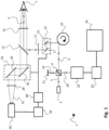
- an optical coherent tomography [OCT] system is generally indicated by reference numeral 1.
- the system includes a radiation source 3 providing a beam 5 of imaging radiation.
- the beam 5 is directed towards an eye 7 of a human or animal, which eye 7 is to be examined.
- the optical coherent tomography system 1 allows for example to examine the fundus of the eye 7.
- the beam 5 of imaging radiation is directed towards the eye 7 by means of a number of optical elements (10, 11, 12, 13 and 15).
- the optical elements for directing the beam 5 of imaging radiation may include lenses 11 and 13 for correctly focusing of the radiation.
- the optical elements further include a mirror element 12 which comprises a specular reflective surface on one side, but which is transmissive on the other side such as to allow the camera 30 to have a field of view with the eye 7 (as will be explained later).
- the optical elements further includes scanning optics 10 comprising a rotatable polygon mirror 10. By rotating the mirror 10, a scanning motion of the beam 5 in the optical path between the mirror 10 and the eye 7 can be obtained. This scanning motion provided by polygon mirror 10 may be used to scan the beam 5 across an examination area on the fundus of the eye 7.
- the implementation of scanning based on a rotating polygon mirror is merely an example, and many other methods and units may be applied here to provide the scanning. Such units may generally be referred to as ⁇ optical scanning units'.
- a reflected portion 6 of the imaging radiation follows the same optical path from the fundus of the eye 7 back to the beam splitter 9.
- the beam splitter 9 forms the heart of a Michelson type interferometer. Although in figure 1 and 2 a Michelson type interferometer is illustrated, the skilled person may appreciate that any other type of interferometer (such as a Mach-Zehnder interferometer (MZI)) may be applied as well. The invention is not limited to a specific type of interferometer.
- the reflected portion 6 of the beam 5 impinges on the beam splitter 9 and is directed towards leg 20 which impinges on optical sensor 23.
- the beam splitter 9 splits the beam 5 of imaging radiation obtained from radiation source 3 such as to create a reference beam 19 in addition to the remainder of the beam 5 which is directed towards the eye 7.
- the reference beam 19 is reflected upon a mirror 21 and part of the reflected radiation will be transmitted into leg 20 towards the optical sensor 23.
- analysis unit 25 is able to create the OCT image, and provide the OCT image of the examination area of the fundus of eye 7 to the display apparatus 26.
- the image obtained may be stored in a memory or provided to a network server or other means.
- the OCT system comprises a tracking camera 30.
- the tracking camera 30 comprises a field of view 31 directed towards optical element 28 for focusing, and via half mirror 12 and optical element 13 to the fundus of the eye 7. Tracking may for example be a fundus camera which allows to recreate a detailed image of the fundus of the eye.
- the images obtained with tracking camera 30 are analyzed by analysis unit 39 and our provided to feedback controller 40 which controls optical correction unit 15.
- Optical correction unit 15 comprises galvanometer actuated mirrors 16 and 17 which allow to precisely correct the beam 5 in the x and y directions (i.e. the directions perpendicular to the optical axis). Using the optical correction unit 15, the direction of the beam 5 of imaging radiation can be adapted to correct for the displacements of the eye 7.
- the feedback controller 40 further controls camera image correction unit 34 comprising galvanometer actuated mirrors 35 and 36 for adapting the direction of the field of view 31 of the tracking camera in the x and y direction.
- camera image correction unit 34 comprising galvanometer actuated mirrors 35 and 36 for adapting the direction of the field of view 31 of the tracking camera in the x and y direction.
- any relative movement between the examination area of the OCT imaging and the image area of the tracking camera will be down to a minimum (e.g. only due to inaccuracies or differences between the optical correction unit 15 or the camera image correction unit 34).
- This further allows to reduce the size of the tracking images.
- the analysis of subsequent tracking images to detect displacements of the fundus can be performed faster, thereby also allowing a higher imaging rate (number of images taken per second) of the tracking camera. Due to the higher imaging rate, displacements caused by eye motion result in smaller deviations between subsequent images, and the system is therefore better capable of following the eye movement and correcting for this. As a result, the accuracy and resolution of the OCT image can be improved.
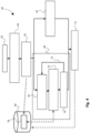
- FIG. 2 A further embodiment of the present invention is illustrated in figure 2 .
- elements performing a similar function for being identical to the embodiment illustrated in figure 1 have been indicated with the same reference numerals. Such elements are only further discussed hereinbelow where needed.
- the optical correction unit 15 also performs the correction of the field of view of the tracking camera 30.
- the optical correction unit 15 and the camera image correction unit 34 of figure 1 have been integrated into a single element in the embodiment of figure 2 . All corrections that are performed by the optical correction unit 15 on the beam 5 of imaging radiation of the OCT system are automatically also applied to the field of view 31 of tracking camera 30. As a result, the location of the examination area for OCT imaging will be fixed relative to the image area of the tracking image of tracking camera 30.
- the size and location of the examination area of the fundus of the eye 7 may differ from one image to the other obtained with the OCT system.
- the examination area of the OCT image may for example always recite in the middle of the tracking image (unless the location or orientation of the camera 30 itself may change).
- the present embodiment illustrated in figure 2 provides several advantages.
- the overall system set up becomes less complex, and the whole OCT system illustrated in figure 2 comprises less elements.
- the whole OCT system illustrated in figure 2 comprises less elements.
- This allows the image area of the tracking image to be smaller, but most importantly, a further source of measurement errors caused by discrepancies between the image area and the examination area is excluded.
- each correction unit is illustrated comprising two galvanometer coupled mirrors which allow correction of the direction in the x and y direction (i.e. perpendicular to the optical path).
- a single optical correction unit 15 enables to correct both the field of view 31 of the tracking camera 30 as well as the beam 5 of imaging radiation provided by the OCT apparatus 50 to be corrected in both the x and y direction (perpendicular to the optical path).
- Figure 3 further illustrates the beam 5 impinging on the fundus 8 of eye 7, as well as the schematic imaging area on fundus 8 for the tracking image. Scanning of the beam 5 across the examination area may be performed by actuating the mirror 51 in the optical path of the beam 5.
- FIG. 4 schematically illustrates an optical coherent tomography method in accordance with an embodiment of the present invention.
- the method 60 includes a first step 62 of aligning the eye 7 with the field of view of the tracking camera 30, such as to set up the system before imaging of the fundus of the eye 7.
- the fundus image obtained with a tracking camera 30 is optimized in step 64 by focusing at the retina of the eye 7, and for example by moving to a location on the fundus having a high contrast.
- This for example may be the optical disc on the retina, but may likewise include veins or arteries, or any other structures providing a sufficient contrast on the surface of the fundus.
- Steps 62 and 64 together form the initialization of the system: setting up the system for performing the OCT imaging.
- SNR signal to noise ratio
- a high imaging rate of the tracking camera is desired such as to make the magnitude of the displacements between subsequent images of the tracking camera as small as possible.
- Small displacements detected at a high imaging rate enable to closely follow the movements of the eye with the tracking camera 30 as well as with the OCT beam 5.
- increasing the imaging rate of the tracking camera automatically reduces the maximum exposure time that can be used for obtaining each of the subsequent tracking images. A shorter exposure time reduces the signal-to-noise ratio (SNR), thereby complicating the detection of the displacements.
- the size of the tracking images can be reduced.
- the processing of the subsequent tracking images can be performed faster, which allows more exposure time per tracking image to be available. Therefore, the reduction of the size of the tracking images already at least partly makes up for the higher imaging rate and decreased exposure time.
- the method further includes a step of providing a reference tracking image (step 65).
- This reference image is obtained in step 65 in figure 4 prior to obtaining the subsequent tracking images in branch 68 of the method of figure 4 .
- a reference image is obtained using a long or at least long enough exposure time.
- the reference image therefore comprises a high signal-to-noise ratio and reveals many details on the fundus of the eye.
- the use of a reference image obtained with a long enough exposure time greatly reduces inaccuracies in the detection of displacements due to eye movement.
- the use of a reference image with long exposure time e.g. 10 milliseconds
- high illumination power e.g. 10 milliwatt
- the actual OCT imaging starts by performing the OCT image acquisition using the beam of imaging radiation in step 67, while at the same time in a simultaneous process performing the tracking in branch 68 of the process.
- the tracking includes the capturing of high speed tracking images in step 70.
- the high speed tracking images are obtained using a short exposure time, e.g. smaller than 1 millisecond.
- the reference image 78 which is stored in memory 80 of the system, in step 72 the displacement of the fundus is detected based on the obtained tracking image in step 70, and the preceding tracking image obtained before. To enable detection of the displacement, a correlation is made between the highly detailed reference image 78, and the tracking image (and its preceding image) obtained in step 70.
- step 74 when the displacement caused by eye movement has been accurately detected, motion correction is applied in step 74.
- this motion correction is applied both on the field of view 31 of the tracking camera 30 as well as on the beam 5 of imaging radiation of the OCT apparatus.
- the tracking in branch 68 of the method is continued, as is illustrated by arrow 73. Therefore, as long as the OCT imaging is being performed, new tracking images are obtained in step 70 and analyzed in step 72 for detecting any displacement.
- step 75 both the OCT image obtained in step 67 as well as the fundus image (or images) are stored in memory 80.
- FIG 5 An alternative to the method disclosed in figure 4 is illustrated in figure 5.
- Figure 5 starts with step 92 wherein the tracking camera 30 and the eye 7 are aligned, similar as in step 62 of figure 4 .
- step 94 the initialization is performed by focusing at the retina and moving to a location with high contrast, such as the optical disc on the retina (like in step 64 of figure 4 ).
- the step of obtaining a reference image having a long exposure time has been omitted, but is implemented in a different manner.
- the step of obtaining a reference image is in figure 5 not a separate step in the method. Instead, a reference image with desired exposure time is created using any number of subsequent tracking images obtained during tracking.
- step 98- 101 the tracking of the fundus and detection of any displacement caused by eye motion is performed in a manner similar to steps 70-74 of figure 4 .
- step 98 the tracking camera 30 captures high speed tracking images with a short exposure time, and stores these high speed tracking images 82 in memory 80.
- the memory 80 also comprises the (highly detailed) reference image 78 obtained with long exposure time in a manner to be explained further below.
- step 99 displacement of the fundus of the eye 7 is detected by analyzing two subsequent high speed tracking images while correlating these high speed tracking images with the detailed reference image 78 from memory 80.
- step 74 motion correction of the field of view 31 of the tracking camera 30 and the beam 5 of the OCT apparatus is performed based on the detected displacement, and thereafter either a new tracking image is taken in step 98 as indicated by arrow 101, or (if step 96 has been completed) the tracking is discontinued and the method continues in step 112.
- step 112 the OCT image obtained in step 96 is stored in memory 80.
- a reference image with high signal-to-noise ratio using long exposure time is created.
- the creation of this reference image is performed 'on the fly'.
- a number of high speed tracking images 82 is retrieved from memory 80 while being stored therein from tracking camera 30.
- the high speed images 82 are analyzed, and an area of overlap that is present in all of the analyzed images is determined. Where necessary, any high speed tracking images that do not have a large enough area of overlap with the other images, or for which the image quality is low, may be discarded from the analysis or may be used for improving only a part of the reference image.
- step 108 the detailed reference image 78 is created based on the data in the area of overlap in the high speed tracking images 82 that were selected in step 107.
- a detailed reference image 78 is stored in memory 80 for use in step 99 for tracking.
- the reference image 78 may be improved by including further tracking images 82 'on the fly', by continuing the process again in step 105.
- this branch of the method may alternatively be discontinued after step 108.
- the embodiment of the method in figure 5 is based on the insight that instead of taking a reference image with a high exposure time in a separate step as illustrated by step 65 of figure 4 , the combination of data from many high speed images 82 having a low exposure time may together result in a reference image having a high exposure time (or the equivalent thereof). As a result, the quality of the reference image 68 will quickly improve while more and more tracking images 82 are being used for creation thereof.
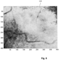
- FIG. 120 An example tracking image of a fundus camera that can be used as tracking camera 30 is illustrated in figure 6 (image 120).
- image 120 structures such as veins on the fundus are visible having a large enough contrast such as to be detectable for displacement detection.
- figure 7B the same prediction was repeated as in figure 7A , but including the use of the clean reference image.
- the clean reference image in the situation of figure 7B was actually the fundus image that was used to generate the test images, without the 80% noise distortion.
- each of the distorted images was first correlated with the clear reference image, and the displacement was determined after correlation with the reference image.
- line 131 is the imposed displacement on the test images.
- the predicted displacement is illustrated by line 133 in graph 130.
- the imposed displacement can be accurately predicted from the test images, showing the potential of this method.
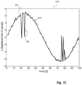
- FIG. 7C To simulate the use of a reference image in a real case, the same procedure as in figure 7B has been repeated in the situation of figure 7C . However, instead of using a clean reference image with 0% noise, the reference image that was used in the simulation of figure 7C included 10% added noise, which is realistic in case a real reference image with sufficient long exposure would be used.
- the imposed displacement is illustrated by line 141.
- the predicted displacement is indicated by line 143.
- the predicted displacement 143 nicely follows the imposed displacement 141 with the exception of some occasional peaks 145 where the displacement is incorrectly determined.
- the measurement errors in the predicted displacement may be easily filtered from the predicted results, for example using a low pass filter, or by fitting, or by any other suitable filtering technique.
- embodiments of the invention may include confocal scanning laser ophthalmology wherein a fundus of an eye is scanned step-by-step by a laser to obtain image data pixel-by-pixel.
- interferometry will not be applied and thus the mirror 21 in figure 1 may be absent or replaced by non-reflective element.
- the beam received by optical sensor 23 will comprise the reflected radiation, and is analyzed by analysis unit 25 to provide the cSLO image.
- the applied optical retinal imaging technique relates to line scanning laser ophthalmology
- additional optics may be present between radiation source 3 and beam splitter 9 to shape the beam 5 such as to provide a line-shaped scanning beam.
- the OCT apparatus 50 may be replaced by, or include, a cSLO or ISLO apparatus.
Landscapes
- Health & Medical Sciences (AREA)
- Life Sciences & Earth Sciences (AREA)
- Physics & Mathematics (AREA)
- Engineering & Computer Science (AREA)
- General Health & Medical Sciences (AREA)
- Surgery (AREA)
- Biophysics (AREA)
- Heart & Thoracic Surgery (AREA)
- Medical Informatics (AREA)
- Molecular Biology (AREA)
- Ophthalmology & Optometry (AREA)
- Animal Behavior & Ethology (AREA)
- Biomedical Technology (AREA)
- Public Health (AREA)
- Veterinary Medicine (AREA)
- General Physics & Mathematics (AREA)
- Nuclear Medicine, Radiotherapy & Molecular Imaging (AREA)
- Radiology & Medical Imaging (AREA)
- Theoretical Computer Science (AREA)
- Eye Examination Apparatus (AREA)
Claims (15)
- Optisches Netzhautbildgebungsverfahren (60, 90), umfassend:Bereitstellen eines Strahls (3) einer bildgebenden Strahlung von einer Strahlungsquelle (3) einer optischen Netzhautbildgebungsvorrichtung (1);Richten des Strahls bildgebender Strahlung unter Verwendung einer Richtoptik auf einen Augenhintergrund eines menschlichen oder tierischen Auges (7) und Empfangen eines reflektierten Teils der Bildgebungsstrahlung durch die optische Netzhautbildgebungsvorrichtung;wobei das Verfahren ferner umfasst:Bereitstellen, durch eine für die Erfassung von Bildern aus einem Sichtfeld konfigurierte Trackingkamera (30), eines Trackingbilds eines Bildbereichs, der wenigstens einen Teil des Augenhintergrunds abdeckt; Analyse des Trackingbilds zur Erfassung einer Verschiebung des Augenhintergrunds; undAnpassen, wenigstens abhängig von der erfassten Verschiebung, einer Richtung des Strahls bildgebender Strahlung durch Betätigen einer optischen Korrektureinheit (15) der Richtoptik; dadurch gekennzeichnet, dasszusätzlich zu dem Anpassen der Richtung des Strahls bildgebender Strahlung ein Anpassen einer Position des Bildbereichs auf dem Augenhintergrund, der von der Trackingkamera wenigstens abhängig von der erfassten Verschiebung abgebildet wird.
- Optisches Netzhautbildgebungsverfahren nach Anspruch 1, wobei die Anpassung der Position des Bildbereichs auf dem Augenhintergrund erzielt wird durch Anordnung der Trackingkamera, sodass sie ein optisches Trackingsignal des Bildbereichs von der Trackingkamera über die optische Korrektureinheit empfängt.
- Optisches Netzhaut-Bildgebungsverfahren nach einem der vorhergehenden Ansprüche, wobei der Schritt des Bereitstellens des Trackingbilds nachfolgend durchgeführt wird, um mehrere nachfolgende Trackingbilder während des Bereitstellens des Strahls der Bildgebungsstrahlung bereitzustellen, ferner umfassend einen Schritt eines Bereitstellens eines Referenz-Trackingbilds, wobei das Referenz-Trackingbild unter Verwendung einer Belichtungszeit erhalten wird, die länger ist als eine Belichtungszeit, die für die nachfolgenden Trackingbilder verwendet wird.
- Optisches Netzhautbildgebungsverfahren nach Anspruch 3, wobei der Schritt des Bereitstellens eines Referenz-Trackingbildes entweder durchgeführt wird durch:Erhalten des Referenz-Trackingbildes als separater Schritt, der vor den Schritten der nachfolgenden Bereitstellung der nachfolgenden Trackingbilder durchgeführt wird; oderErhalten des Referenz-Trackingbildes durch Kombination von Bilddaten aus zwei oder mehr der nachfolgenden Trackingbilder, um beispielsweise die längere Belichtungszeit des Referenz-Trackingbildes zu erhalten.
- Optisches Netzhautbildgebungsverfahren nach einem der vorhergehenden Ansprüche, wobei die Tracking-Kamera eine Augenhintergrundkamera ist.
- Optisches Netzhautbildgebungsverfahren nach einem der vorhergehenden Ansprüche, wobei das Verfahren der optischen Netzhautbildgebung wenigstens eine Gruppe ist, die umfasst: ein optisches Kohärenztomographieverfahren, ein konfokales scannendes Laserophthalmoskopieverfahren oder ein Linienscanning-Laserophthalmoskopieverfahren.
- Optisches Netzhautbildgebungssystem (1), umfassendeine optische Netzhautbildgebungsvorrichtung mit einer Strahlungsquelle (3), die zur Bereitstellung eines Strahls (5) bildgebender Strahlung, einem optischen Empfänger (23), der zum Empfangen eines reflektierten Teils der bildgebenden Strahlung konfiguriert ist, und einer Analyseeinheit (25), die zur Analyse des erhaltenen reflektierten Teils der bildgebenden Strahlung konfiguriert ist,wobei das System ferner aufweist:eine zur Ausrichtung des Strahls bildgebender Strahlung auf einen Augenhintergrund eines menschlichen oder tierischen Auges konfigurierte Richtoptik, und eine Trackingkamera (30), die zur Bereitstellung eines Trackingbildes eines Bildbereichs, der wenigstens einen Teil des Augenhintergrunds abdeckt, wobei die Trackingkamera für die Erfassung von Bildern aus einem Sichtfeld konfiguriert ist, und eine Steuereinheit (39, 40), die zum Empfangen und Analysieren des Trackingbildes zur Erfassung einer Verschiebung des Augenhintergrunds während seiner Bestrahlung durch die optische Netzhautbildgebungsvorrichtung konfiguriert ist;wobei die Richtoptik umfasst:eine optische Korrektureinheit (15), die operativ mit der Steuereinheit verbunden ist und die konfiguriert ist, dass sie das Anpassen einer Richtung des Strahls bildgebender Strahlung wenigstens abhängig von der erfassten Verschiebung durch Betätigung der optischen Korrektureinheit ermöglicht;gekennzeichnet durch
eine Kamerabildkorrektureinheit (34), die, zusätzlich zur Anpassung der Richtung des Strahls bildgebender Strahlung, zur Anpassung, einer Position des Bildbereichs auf dem Augenhintergrund, der von der Trackingkamera abgebildet wird wenigstens abhängig von der erfassten Verschiebung konfiguriert ist. - Optisches Netzhaut-Bildgebungssystem nach Anspruch 7, wobei die Kamera-Bildkorrektureinheit die optische Korrektureinheit aufweist.
- Optisches Netzhautbildgebungssystem nach einem der Ansprüche 7 oder 8, wobei die Trackingkamera wenigstens eine der folgenden ist: eine Augenhintergrundkamera.
- Optisches Netzhautbildgebungssystem nach einem der Ansprüche 7 bis 9, wobei die optische Korrektureinheit wenigstens einen Spiegel aufweist, der mit einem Aktuator verbunden ist, um wenigstens eine der Ausrichtung oder Position des Spiegels in Bezug auf den Strahl der Bildgebungsstrahlung zur Anpassung seiner Richtung zu steuern.
- Optisches Netzhautbildgebungssystem nach einem der Ansprüche 7 bis 10, ferner umfassend eine Scaneinheit zum Scannen des Strahls der Bildgebung über den Augenhintergrundhinweg.
- Optisches Netzhaut-Bildgebungssystem nach einem der Ansprüche 7 bis 11, wobei die Steuereinheit so angeordnet ist, dass sie während des Bereitstellens des Strahls der Bildgebungsstrahlung mehrere nachfolgende Trackingbilder empfängt, wobei die Steuereinheit ferner so angeordnet ist, dass sie ein Referenz-Trackingbild erhält, wobei das Referenz-Trackingbild unter Verwendung einer Belichtungszeit und/oder Beleuchtungsleistung erhalten wird, die größer ist als die für die nachfolgenden Trackingbilder verwendete.
- Optisches Netzhautbildgebungssystem nach Anspruch 12, wobei die Steuereinheit so angeordnet ist, dass sie das Referenz-Trackingbild erhält, indem Bilddaten aus zwei oder mehr der nachfolgenden Trackingbilder kombiniert werden, um die längere Belichtungszeit des Referenz-Trackingbildes zu erhalten.
- Optisches Netzhautbildgebungssystem nach einem der Ansprüche 7 bis 11, wobei das optische Netzhautbildgebungssystem wenigstens eine Gruppe umfasst, die umfasst: ein optisches Kohärenztomographiesystem, ein konfokales scannendes Laserophthalmoskopiesystem oder ein Linienscanning-Laserophthalmoskopiesystem.
- Computerlesbares Medium, umfassend ein Computerprogrammprodukt, das Anweisungen umfasst, die, wenn sie von einem optischen Netzhautbildgebungssystem gemäß einem der Ansprüche 7 bis 14 durchgeführt werden, das System veranlasst, ein Verfahren durchzuführen, das umfasst:Steuern einer Strahlungsquelle einer optischen Netzhautbildgebungsvorrichtung, die vom System umfasst ist, um einen Strahl bildgebender Strahlung bereitzustellen; und Steuern einer Richtoptik, um den Strahl bildgebender Strahlung auf einen Augenhintergrundeines menschlichen oder tierischen Auges zu lenken; und Steuern der optischen Netzhautbildgebungsvorrichtung, um einen reflektierten Teil der bildgebenden Strahlung zu empfangen;das Verfahren ferner umfassend:Steuern einer Trackingkamera, um ein Trackingbild eines Bildbereichs bereitzustellen, der wenigstens einen Teil des Augenhintergrunds abdeckt, und Erhalten und Analysieren des Trackingbilds durch eine Steuereinheit zur Erfassung einer Verschiebung des Augenhintergrunds; undAnpassen, wenigstens abhängig von der erfassten Verschiebung, einer Richtung des Strahls bildgebender Strahlung durch Betätigen einer optischen Korrektureinheit der Richtoptik; gekennzeichnet durchzusätzlich zu dem Anpassen der Richtung des Strahls bildgebender Strahlung, Anpassen einer Position des Bildbereichs auf dem Augenhintergrund, der von der Trackingkamera abgebildet wird wenigstens abhängig von der erfassten Verschiebung.
Applications Claiming Priority (2)
| Application Number | Priority Date | Filing Date | Title |
|---|---|---|---|
| EP15159891.9A EP3069653A1 (de) | 2015-03-19 | 2015-03-19 | Optisches kohärenztomografieverfahren, system und computerprogrammprodukt dafür |
| PCT/NL2016/050186 WO2016148569A1 (en) | 2015-03-19 | 2016-03-17 | Optical coherence tomography method, system and computer program product therefor |
Publications (2)
| Publication Number | Publication Date |
|---|---|
| EP3270763A1 EP3270763A1 (de) | 2018-01-24 |
| EP3270763B1 true EP3270763B1 (de) | 2023-09-06 |
Family
ID=52736876
Family Applications (2)
| Application Number | Title | Priority Date | Filing Date |
|---|---|---|---|
| EP15159891.9A Withdrawn EP3069653A1 (de) | 2015-03-19 | 2015-03-19 | Optisches kohärenztomografieverfahren, system und computerprogrammprodukt dafür |
| EP16718514.9A Active EP3270763B1 (de) | 2015-03-19 | 2016-03-17 | Optisches kohärenztomografieverfahren, system und computerprogrammprodukt dafür |
Family Applications Before (1)
| Application Number | Title | Priority Date | Filing Date |
|---|---|---|---|
| EP15159891.9A Withdrawn EP3069653A1 (de) | 2015-03-19 | 2015-03-19 | Optisches kohärenztomografieverfahren, system und computerprogrammprodukt dafür |
Country Status (3)
| Country | Link |
|---|---|
| US (1) | US10743759B2 (de) |
| EP (2) | EP3069653A1 (de) |
| WO (1) | WO2016148569A1 (de) |
Families Citing this family (10)
| Publication number | Priority date | Publication date | Assignee | Title |
|---|---|---|---|---|
| CA3048197A1 (en) | 2016-12-21 | 2018-06-28 | Acucela Inc. | Miniaturized mobile, low cost optical coherence tomography system for home based ophthalmic applications |
| WO2019155344A1 (en) * | 2018-02-09 | 2019-08-15 | Novartis Ag | System inverting controller for laser scanning systems |
| JP7123626B2 (ja) * | 2018-05-24 | 2022-08-23 | キヤノン株式会社 | 眼底撮影装置およびその制御方法 |
| EP3809948A4 (de) | 2018-06-20 | 2022-03-16 | Acucela Inc. | Miniaturisiertes kostengünstiges optisches kohärenztomografiesystem für ophthalmische anwendungen zuhause |
| US11730363B2 (en) | 2019-12-26 | 2023-08-22 | Acucela Inc. | Optical coherence tomography patient alignment system for home based ophthalmic applications |
| US10959613B1 (en) | 2020-08-04 | 2021-03-30 | Acucela Inc. | Scan pattern and signal processing for optical coherence tomography |
| CA3188255A1 (en) | 2020-08-14 | 2022-02-17 | Ryo Kubota | System and method for optical coherence tomography a-scan decurving |
| US11393094B2 (en) | 2020-09-11 | 2022-07-19 | Acucela Inc. | Artificial intelligence for evaluation of optical coherence tomography images |
| AU2021352417A1 (en) | 2020-09-30 | 2023-04-06 | Acucela Inc. | Myopia prediction, diagnosis, planning, and monitoring device |
| EP4312717A4 (de) | 2021-03-24 | 2025-02-19 | Acucela Inc. | Überwachungsvorrichtung für axiale längenmessung |
Family Cites Families (9)
| Publication number | Priority date | Publication date | Assignee | Title |
|---|---|---|---|---|
| US5094523A (en) * | 1990-05-11 | 1992-03-10 | Eye Research Institute Of Retina Foundation | Bidirectional light steering apparatus |
| US6325512B1 (en) * | 2000-10-31 | 2001-12-04 | Carl Zeiss, Inc. | Retinal tracking assisted optical coherence tomography |
| EP1602321A1 (de) * | 2004-06-02 | 2005-12-07 | SensoMotoric Instruments GmbH | Methode und Gerät zur bildgestützten Augenverfolgung bei Apparaten zur Diagnose oder Chirurgie der Retina |
| US7805009B2 (en) * | 2005-04-06 | 2010-09-28 | Carl Zeiss Meditec, Inc. | Method and apparatus for measuring motion of a subject using a series of partial images from an imaging system |
| WO2007127291A2 (en) * | 2006-04-24 | 2007-11-08 | Physical Sciences, Inc. | Stabilized retinal imaging with adaptive optics |
| WO2012149420A1 (en) | 2011-04-29 | 2012-11-01 | Optovue, Inc. | Improved imaging with real-time tracking using optical coherence tomography |
| JP6102369B2 (ja) * | 2013-03-14 | 2017-03-29 | 株式会社ニデック | 眼底撮影装置 |
| US9456746B2 (en) * | 2013-03-15 | 2016-10-04 | Carl Zeiss Meditec, Inc. | Systems and methods for broad line fundus imaging |
| EP3021735A4 (de) * | 2013-07-19 | 2017-04-19 | The General Hospital Corporation | Bestimmung der augenbewegung mittels netzhautabbildung mit rückkopplung |
-
2015
- 2015-03-19 EP EP15159891.9A patent/EP3069653A1/de not_active Withdrawn
-
2016
- 2016-03-17 WO PCT/NL2016/050186 patent/WO2016148569A1/en not_active Ceased
- 2016-03-17 US US15/559,266 patent/US10743759B2/en active Active
- 2016-03-17 EP EP16718514.9A patent/EP3270763B1/de active Active
Also Published As
| Publication number | Publication date |
|---|---|
| EP3069653A1 (de) | 2016-09-21 |
| WO2016148569A1 (en) | 2016-09-22 |
| EP3270763A1 (de) | 2018-01-24 |
| US20180092527A1 (en) | 2018-04-05 |
| US10743759B2 (en) | 2020-08-18 |
Similar Documents
| Publication | Publication Date | Title |
|---|---|---|
| EP3270763B1 (de) | Optisches kohärenztomografieverfahren, system und computerprogrammprodukt dafür | |
| CN104799810B (zh) | 光学相干断层成像设备及其控制方法 | |
| EP2762060B1 (de) | Optische-Kohärenz-Tomographiebildgebungsvorrichtung und Steuerverfahren dafür | |
| DK2822448T3 (en) | APPARATUS FOR AN EYE OPTICAL COHENSE TOMOGRAPHY AND PROCEDURE FOR OPTICAL COHENSE TOMOGRAPHY OF AN EYE | |
| CN102970919B (zh) | 光学相干断层图像摄像设备及其方法 | |
| EP2497413A1 (de) | Fotografiervorrichtung und Fotografierverfahren | |
| US9554700B2 (en) | Optical coherence tomographic imaging apparatus and method of controlling the same | |
| DK2709577T3 (en) | UNIT TO INVESTIGATE OR TREAT A HUMAN EYE | |
| WO2019225290A1 (ja) | 撮影装置及びその制御方法 | |
| EP3216388B1 (de) | Ophthalmische vorrichtung und bildgebungsverfahren | |
| EP3050497B1 (de) | Ophthalmische vorrichtung und verfahren zur steuerung davon | |
| JP2019201951A (ja) | 撮影装置及びその制御方法 | |
| JP5587014B2 (ja) | 眼科装置 | |
| JP6544071B2 (ja) | 光コヒーレンストモグラフィ装置、および光コヒーレンストモグラフィ制御プログラム | |
| EP3459434B1 (de) | Ophthalmologische vorrichtung und verfahren zur steuerung davon | |
| JP2014147504A (ja) | 光干渉断層撮像装置およびその制御方法 | |
| JP6486427B2 (ja) | 光干渉断層撮像装置およびその制御方法 | |
| JP7722064B2 (ja) | 眼科撮影装置 | |
| JP2025153144A (ja) | Oct画像処理プログラムおよびoct画像処理装置 | |
| JP2024053922A (ja) | 眼科画像処理装置、眼科画像処理方法、及びプログラム | |
| JP2019170807A (ja) | 撮像装置およびその制御方法 |
Legal Events
| Date | Code | Title | Description |
|---|---|---|---|
| STAA | Information on the status of an ep patent application or granted ep patent |
Free format text: STATUS: THE INTERNATIONAL PUBLICATION HAS BEEN MADE |
|
| PUAI | Public reference made under article 153(3) epc to a published international application that has entered the european phase |
Free format text: ORIGINAL CODE: 0009012 |
|
| STAA | Information on the status of an ep patent application or granted ep patent |
Free format text: STATUS: REQUEST FOR EXAMINATION WAS MADE |
|
| 17P | Request for examination filed |
Effective date: 20171003 |
|
| AK | Designated contracting states |
Kind code of ref document: A1 Designated state(s): AL AT BE BG CH CY CZ DE DK EE ES FI FR GB GR HR HU IE IS IT LI LT LU LV MC MK MT NL NO PL PT RO RS SE SI SK SM TR |
|
| AX | Request for extension of the european patent |
Extension state: BA ME |
|
| DAV | Request for validation of the european patent (deleted) | ||
| DAX | Request for extension of the european patent (deleted) | ||
| STAA | Information on the status of an ep patent application or granted ep patent |
Free format text: STATUS: EXAMINATION IS IN PROGRESS |
|
| 17Q | First examination report despatched |
Effective date: 20210217 |
|
| GRAP | Despatch of communication of intention to grant a patent |
Free format text: ORIGINAL CODE: EPIDOSNIGR1 |
|
| STAA | Information on the status of an ep patent application or granted ep patent |
Free format text: STATUS: GRANT OF PATENT IS INTENDED |
|
| INTG | Intention to grant announced |
Effective date: 20230324 |
|
| P01 | Opt-out of the competence of the unified patent court (upc) registered |
Effective date: 20230522 |
|
| GRAS | Grant fee paid |
Free format text: ORIGINAL CODE: EPIDOSNIGR3 |
|
| GRAA | (expected) grant |
Free format text: ORIGINAL CODE: 0009210 |
|
| STAA | Information on the status of an ep patent application or granted ep patent |
Free format text: STATUS: THE PATENT HAS BEEN GRANTED |
|
| AK | Designated contracting states |
Kind code of ref document: B1 Designated state(s): AL AT BE BG CH CY CZ DE DK EE ES FI FR GB GR HR HU IE IS IT LI LT LU LV MC MK MT NL NO PL PT RO RS SE SI SK SM TR |
|
| REG | Reference to a national code |
Ref country code: GB Ref legal event code: FG4D |
|
| REG | Reference to a national code |
Ref country code: CH Ref legal event code: EP |
|
| REG | Reference to a national code |
Ref country code: DE Ref legal event code: R096 Ref document number: 602016082512 Country of ref document: DE |
|
| REG | Reference to a national code |
Ref country code: IE Ref legal event code: FG4D |
|
| REG | Reference to a national code |
Ref country code: NL Ref legal event code: FP |
|
| REG | Reference to a national code |
Ref country code: LT Ref legal event code: MG9D |
|
| PG25 | Lapsed in a contracting state [announced via postgrant information from national office to epo] |
Ref country code: GR Free format text: LAPSE BECAUSE OF FAILURE TO SUBMIT A TRANSLATION OF THE DESCRIPTION OR TO PAY THE FEE WITHIN THE PRESCRIBED TIME-LIMIT Effective date: 20231207 |
|
| PG25 | Lapsed in a contracting state [announced via postgrant information from national office to epo] |
Ref country code: SE Free format text: LAPSE BECAUSE OF FAILURE TO SUBMIT A TRANSLATION OF THE DESCRIPTION OR TO PAY THE FEE WITHIN THE PRESCRIBED TIME-LIMIT Effective date: 20230906 Ref country code: RS Free format text: LAPSE BECAUSE OF FAILURE TO SUBMIT A TRANSLATION OF THE DESCRIPTION OR TO PAY THE FEE WITHIN THE PRESCRIBED TIME-LIMIT Effective date: 20230906 Ref country code: NO Free format text: LAPSE BECAUSE OF FAILURE TO SUBMIT A TRANSLATION OF THE DESCRIPTION OR TO PAY THE FEE WITHIN THE PRESCRIBED TIME-LIMIT Effective date: 20231206 Ref country code: LV Free format text: LAPSE BECAUSE OF FAILURE TO SUBMIT A TRANSLATION OF THE DESCRIPTION OR TO PAY THE FEE WITHIN THE PRESCRIBED TIME-LIMIT Effective date: 20230906 Ref country code: LT Free format text: LAPSE BECAUSE OF FAILURE TO SUBMIT A TRANSLATION OF THE DESCRIPTION OR TO PAY THE FEE WITHIN THE PRESCRIBED TIME-LIMIT Effective date: 20230906 Ref country code: HR Free format text: LAPSE BECAUSE OF FAILURE TO SUBMIT A TRANSLATION OF THE DESCRIPTION OR TO PAY THE FEE WITHIN THE PRESCRIBED TIME-LIMIT Effective date: 20230906 Ref country code: GR Free format text: LAPSE BECAUSE OF FAILURE TO SUBMIT A TRANSLATION OF THE DESCRIPTION OR TO PAY THE FEE WITHIN THE PRESCRIBED TIME-LIMIT Effective date: 20231207 Ref country code: FI Free format text: LAPSE BECAUSE OF FAILURE TO SUBMIT A TRANSLATION OF THE DESCRIPTION OR TO PAY THE FEE WITHIN THE PRESCRIBED TIME-LIMIT Effective date: 20230906 |
|
| REG | Reference to a national code |
Ref country code: AT Ref legal event code: MK05 Ref document number: 1607383 Country of ref document: AT Kind code of ref document: T Effective date: 20230906 |
|
| PG25 | Lapsed in a contracting state [announced via postgrant information from national office to epo] |
Ref country code: IS Free format text: LAPSE BECAUSE OF FAILURE TO SUBMIT A TRANSLATION OF THE DESCRIPTION OR TO PAY THE FEE WITHIN THE PRESCRIBED TIME-LIMIT Effective date: 20240106 |
|
| PG25 | Lapsed in a contracting state [announced via postgrant information from national office to epo] |
Ref country code: AT Free format text: LAPSE BECAUSE OF FAILURE TO SUBMIT A TRANSLATION OF THE DESCRIPTION OR TO PAY THE FEE WITHIN THE PRESCRIBED TIME-LIMIT Effective date: 20230906 |
|
| PG25 | Lapsed in a contracting state [announced via postgrant information from national office to epo] |
Ref country code: ES Free format text: LAPSE BECAUSE OF FAILURE TO SUBMIT A TRANSLATION OF THE DESCRIPTION OR TO PAY THE FEE WITHIN THE PRESCRIBED TIME-LIMIT Effective date: 20230906 |
|
| PG25 | Lapsed in a contracting state [announced via postgrant information from national office to epo] |
Ref country code: SM Free format text: LAPSE BECAUSE OF FAILURE TO SUBMIT A TRANSLATION OF THE DESCRIPTION OR TO PAY THE FEE WITHIN THE PRESCRIBED TIME-LIMIT Effective date: 20230906 Ref country code: RO Free format text: LAPSE BECAUSE OF FAILURE TO SUBMIT A TRANSLATION OF THE DESCRIPTION OR TO PAY THE FEE WITHIN THE PRESCRIBED TIME-LIMIT Effective date: 20230906 Ref country code: IS Free format text: LAPSE BECAUSE OF FAILURE TO SUBMIT A TRANSLATION OF THE DESCRIPTION OR TO PAY THE FEE WITHIN THE PRESCRIBED TIME-LIMIT Effective date: 20240106 Ref country code: ES Free format text: LAPSE BECAUSE OF FAILURE TO SUBMIT A TRANSLATION OF THE DESCRIPTION OR TO PAY THE FEE WITHIN THE PRESCRIBED TIME-LIMIT Effective date: 20230906 Ref country code: EE Free format text: LAPSE BECAUSE OF FAILURE TO SUBMIT A TRANSLATION OF THE DESCRIPTION OR TO PAY THE FEE WITHIN THE PRESCRIBED TIME-LIMIT Effective date: 20230906 Ref country code: CZ Free format text: LAPSE BECAUSE OF FAILURE TO SUBMIT A TRANSLATION OF THE DESCRIPTION OR TO PAY THE FEE WITHIN THE PRESCRIBED TIME-LIMIT Effective date: 20230906 Ref country code: AT Free format text: LAPSE BECAUSE OF FAILURE TO SUBMIT A TRANSLATION OF THE DESCRIPTION OR TO PAY THE FEE WITHIN THE PRESCRIBED TIME-LIMIT Effective date: 20230906 Ref country code: SK Free format text: LAPSE BECAUSE OF FAILURE TO SUBMIT A TRANSLATION OF THE DESCRIPTION OR TO PAY THE FEE WITHIN THE PRESCRIBED TIME-LIMIT Effective date: 20230906 Ref country code: PT Free format text: LAPSE BECAUSE OF FAILURE TO SUBMIT A TRANSLATION OF THE DESCRIPTION OR TO PAY THE FEE WITHIN THE PRESCRIBED TIME-LIMIT Effective date: 20240108 |
|
| PG25 | Lapsed in a contracting state [announced via postgrant information from national office to epo] |
Ref country code: PL Free format text: LAPSE BECAUSE OF FAILURE TO SUBMIT A TRANSLATION OF THE DESCRIPTION OR TO PAY THE FEE WITHIN THE PRESCRIBED TIME-LIMIT Effective date: 20230906 Ref country code: IT Free format text: LAPSE BECAUSE OF FAILURE TO SUBMIT A TRANSLATION OF THE DESCRIPTION OR TO PAY THE FEE WITHIN THE PRESCRIBED TIME-LIMIT Effective date: 20230906 |
|
| REG | Reference to a national code |
Ref country code: DE Ref legal event code: R097 Ref document number: 602016082512 Country of ref document: DE |
|
| PG25 | Lapsed in a contracting state [announced via postgrant information from national office to epo] |
Ref country code: DK Free format text: LAPSE BECAUSE OF FAILURE TO SUBMIT A TRANSLATION OF THE DESCRIPTION OR TO PAY THE FEE WITHIN THE PRESCRIBED TIME-LIMIT Effective date: 20230906 |
|
| PLBE | No opposition filed within time limit |
Free format text: ORIGINAL CODE: 0009261 |
|
| STAA | Information on the status of an ep patent application or granted ep patent |
Free format text: STATUS: NO OPPOSITION FILED WITHIN TIME LIMIT |
|
| PG25 | Lapsed in a contracting state [announced via postgrant information from national office to epo] |
Ref country code: DK Free format text: LAPSE BECAUSE OF FAILURE TO SUBMIT A TRANSLATION OF THE DESCRIPTION OR TO PAY THE FEE WITHIN THE PRESCRIBED TIME-LIMIT Effective date: 20230906 Ref country code: SI Free format text: LAPSE BECAUSE OF FAILURE TO SUBMIT A TRANSLATION OF THE DESCRIPTION OR TO PAY THE FEE WITHIN THE PRESCRIBED TIME-LIMIT Effective date: 20230906 |
|
| 26N | No opposition filed |
Effective date: 20240607 |
|
| REG | Reference to a national code |
Ref country code: CH Ref legal event code: PL |
|
| PG25 | Lapsed in a contracting state [announced via postgrant information from national office to epo] |
Ref country code: BG Free format text: LAPSE BECAUSE OF FAILURE TO SUBMIT A TRANSLATION OF THE DESCRIPTION OR TO PAY THE FEE WITHIN THE PRESCRIBED TIME-LIMIT Effective date: 20230906 |
|
| PG25 | Lapsed in a contracting state [announced via postgrant information from national office to epo] |
Ref country code: LU Free format text: LAPSE BECAUSE OF NON-PAYMENT OF DUE FEES Effective date: 20240317 |
|
| PG25 | Lapsed in a contracting state [announced via postgrant information from national office to epo] |
Ref country code: MC Free format text: LAPSE BECAUSE OF FAILURE TO SUBMIT A TRANSLATION OF THE DESCRIPTION OR TO PAY THE FEE WITHIN THE PRESCRIBED TIME-LIMIT Effective date: 20230906 |
|
| PG25 | Lapsed in a contracting state [announced via postgrant information from national office to epo] |
Ref country code: MC Free format text: LAPSE BECAUSE OF FAILURE TO SUBMIT A TRANSLATION OF THE DESCRIPTION OR TO PAY THE FEE WITHIN THE PRESCRIBED TIME-LIMIT Effective date: 20230906 Ref country code: LU Free format text: LAPSE BECAUSE OF NON-PAYMENT OF DUE FEES Effective date: 20240317 Ref country code: BG Free format text: LAPSE BECAUSE OF FAILURE TO SUBMIT A TRANSLATION OF THE DESCRIPTION OR TO PAY THE FEE WITHIN THE PRESCRIBED TIME-LIMIT Effective date: 20230906 |
|
| REG | Reference to a national code |
Ref country code: BE Ref legal event code: MM Effective date: 20240331 |
|
| PG25 | Lapsed in a contracting state [announced via postgrant information from national office to epo] |
Ref country code: BE Free format text: LAPSE BECAUSE OF NON-PAYMENT OF DUE FEES Effective date: 20240331 |
|
| PG25 | Lapsed in a contracting state [announced via postgrant information from national office to epo] |
Ref country code: IE Free format text: LAPSE BECAUSE OF NON-PAYMENT OF DUE FEES Effective date: 20240317 |
|
| PG25 | Lapsed in a contracting state [announced via postgrant information from national office to epo] |
Ref country code: IE Free format text: LAPSE BECAUSE OF NON-PAYMENT OF DUE FEES Effective date: 20240317 Ref country code: BE Free format text: LAPSE BECAUSE OF NON-PAYMENT OF DUE FEES Effective date: 20240331 Ref country code: CH Free format text: LAPSE BECAUSE OF NON-PAYMENT OF DUE FEES Effective date: 20240331 |
|
| PG25 | Lapsed in a contracting state [announced via postgrant information from national office to epo] |
Ref country code: CY Free format text: LAPSE BECAUSE OF FAILURE TO SUBMIT A TRANSLATION OF THE DESCRIPTION OR TO PAY THE FEE WITHIN THE PRESCRIBED TIME-LIMIT; INVALID AB INITIO Effective date: 20160317 |
|
| PG25 | Lapsed in a contracting state [announced via postgrant information from national office to epo] |
Ref country code: HU Free format text: LAPSE BECAUSE OF FAILURE TO SUBMIT A TRANSLATION OF THE DESCRIPTION OR TO PAY THE FEE WITHIN THE PRESCRIBED TIME-LIMIT; INVALID AB INITIO Effective date: 20160317 |
|
| PG25 | Lapsed in a contracting state [announced via postgrant information from national office to epo] |
Ref country code: TR Free format text: LAPSE BECAUSE OF FAILURE TO SUBMIT A TRANSLATION OF THE DESCRIPTION OR TO PAY THE FEE WITHIN THE PRESCRIBED TIME-LIMIT Effective date: 20230906 |
|
| PGFP | Annual fee paid to national office [announced via postgrant information from national office to epo] |
Ref country code: GB Payment date: 20260324 Year of fee payment: 11 |
|
| PGFP | Annual fee paid to national office [announced via postgrant information from national office to epo] |
Ref country code: DE Payment date: 20260319 Year of fee payment: 11 |
|
| PGFP | Annual fee paid to national office [announced via postgrant information from national office to epo] |
Ref country code: NL Payment date: 20260319 Year of fee payment: 11 |
|
| PGFP | Annual fee paid to national office [announced via postgrant information from national office to epo] |
Ref country code: FR Payment date: 20260320 Year of fee payment: 11 |