EP3270571A1 - Dispositif de detection d'une grandeur physique - Google Patents
Dispositif de detection d'une grandeur physique Download PDFInfo
- Publication number
- EP3270571A1 EP3270571A1 EP16179539.8A EP16179539A EP3270571A1 EP 3270571 A1 EP3270571 A1 EP 3270571A1 EP 16179539 A EP16179539 A EP 16179539A EP 3270571 A1 EP3270571 A1 EP 3270571A1
- Authority
- EP
- European Patent Office
- Prior art keywords
- detection device
- transmission time
- time slot
- group
- server entity
- Prior art date
- Legal status (The legal status is an assumption and is not a legal conclusion. Google has not performed a legal analysis and makes no representation as to the accuracy of the status listed.)
- Withdrawn
Links
- 238000001514 detection method Methods 0.000 title claims abstract description 267
- 230000005540 biological transmission Effects 0.000 claims abstract description 313
- 238000004891 communication Methods 0.000 claims abstract description 192
- 238000000034 method Methods 0.000 claims description 22
- 230000001133 acceleration Effects 0.000 claims description 4
- 238000004590 computer program Methods 0.000 claims description 2
- 239000000446 fuel Substances 0.000 claims description 2
- XLYOFNOQVPJJNP-UHFFFAOYSA-N water Substances O XLYOFNOQVPJJNP-UHFFFAOYSA-N 0.000 claims description 2
- 238000010586 diagram Methods 0.000 description 35
- 238000005516 engineering process Methods 0.000 description 5
- 238000005265 energy consumption Methods 0.000 description 2
- 238000010438 heat treatment Methods 0.000 description 2
- 238000004519 manufacturing process Methods 0.000 description 2
- 238000012544 monitoring process Methods 0.000 description 2
- 238000013459 approach Methods 0.000 description 1
- 230000001419 dependent effect Effects 0.000 description 1
- 230000006855 networking Effects 0.000 description 1
- 230000001105 regulatory effect Effects 0.000 description 1
- 230000002618 waking effect Effects 0.000 description 1
Images


Classifications
-
- H—ELECTRICITY
- H04—ELECTRIC COMMUNICATION TECHNIQUE
- H04L—TRANSMISSION OF DIGITAL INFORMATION, e.g. TELEGRAPHIC COMMUNICATION
- H04L67/00—Network arrangements or protocols for supporting network services or applications
- H04L67/01—Protocols
- H04L67/12—Protocols specially adapted for proprietary or special-purpose networking environments, e.g. medical networks, sensor networks, networks in vehicles or remote metering networks
- H04L67/125—Protocols specially adapted for proprietary or special-purpose networking environments, e.g. medical networks, sensor networks, networks in vehicles or remote metering networks involving control of end-device applications over a network
-
- H—ELECTRICITY
- H04—ELECTRIC COMMUNICATION TECHNIQUE
- H04L—TRANSMISSION OF DIGITAL INFORMATION, e.g. TELEGRAPHIC COMMUNICATION
- H04L67/00—Network arrangements or protocols for supporting network services or applications
- H04L67/50—Network services
- H04L67/60—Scheduling or organising the servicing of application requests, e.g. requests for application data transmissions using the analysis and optimisation of the required network resources
- H04L67/62—Establishing a time schedule for servicing the requests
Definitions
- the present invention relates to the field of physical quantity detection and the transmission of data representing the physical quantity over a communication network.
- the term Internet of Things is understood to mean the networking of physical objects via a communication network, which enables, for example, a more efficient monitoring of the physical objects and an exchange of information about the physical objects.
- the Internet of Things is of increasing importance especially in the field of home automation technology and industrial automation technology, wherein different physical quantities, such as a temperature or an energy consumption, are to be detected efficiently.
- heating sensors for billing heating costs are increasingly being equipped with appropriate functionality.
- production processes are to be optimized and carried out more efficiently. Appropriate approaches for this are mostly summarized under the term Industry 4.0.
- the present invention is based on the finding that the above object can be achieved by a detection device to which an identity identifier is assigned and which is designed to receive a broadcast signal from a server entity via a communication network.
- the detection device can be assigned to a group of detection devices, wherein each detection device of the group can communicate with the server entity and receive the broadcast signal.
- the broadcast signal may indicate an occupancy of transmission time slots in a predetermined transmission interval by assigning identity identifiers of the detection devices to transmission time slots.
- the detection device is configured to select a free transmission time slot of the predetermined transmission interval if no transmission time slot is assigned to the identity identifier of the detection device, and to send data in the selected transmission time slot to the server entity via the communication network.
- the detection device can also be designed to select an occupied transmission time slot of the predetermined transmission interval if the assigned transmission time slot is assigned the identity identifier of the detection device.
- Each detection device of the group can therefore independently select and occupy a free transmission time slot in the predetermined transmission interval.
- the server entity can thereupon permanently assign the respective transmission time slot of the respective detection device by assigning the respective identity identifier to the respective transmission time slot.
- the respective detection device can use the now permanently assigned transmission time slot for transmitting data.
- the transmission intervals with the respective transmission time slots can be repeated periodically.
- the invention relates to a detection device for detecting a physical quantity, wherein the detection device of a group of Associated detection devices, wherein each detection device of the group of detection devices is associated with an identity identifier, wherein the group of detection devices is adapted to communicate over a communication network with a server entity, with a detector for detecting the physical size, wherein the detector is configured to output data representing the physical quantity and a communication interface configured to receive a broadcast signal from the server entity via the communication network, the broadcast signal indicating an occupancy of transmission time slots in a predetermined transmission interval by assigning identity identifiers from detection devices to transmission time slots, the communication interface is configured to select a free transmission time slot of the predetermined transmission interval, if no transmission time slot de identity identifier de r is associated with the detection device, and wherein the communication interface is adapted to transmit the data in the selected transmission time slot over the communication network to the server entity.
- the identity identifier of the detection device can be assigned permanently to the detection device during its production.
- the identity identifier may be, for example, a Media Access Control (MAC) address or an International Mobile Station Equipment Identity (IMEI) number associated with the detection device.
- MAC Media Access Control
- IMEI International Mobile Station Equipment Identity
- the communication interface is designed to select an occupied transmission time slot of the predetermined transmission interval if the occupied transmission time slot is assigned the identity identifier of the detection device.
- the broadcast signal comprises a plurality of broadcast signal sections, each broadcast signal section being associated with a transmission slot in the predetermined transmission interval, and wherein the communication interface is configured to extract the plurality of broadcast signal sections from the broadcast signal.
- a free transmission time slot in the predetermined transmission interval may be indicated by a respective empty broadcast signal portion.
- An occupied transmission time slot in the predetermined transmission interval may be indicated, for example, by the display of an identity identifier in the respective broadcast signal portion.
- the broadcast signal having the broadcast signal portions may be arranged in a broadcast time slot.
- the detector is designed to link the data with the identity identifier of the detection device, wherein the communication interface is designed to transmit the data with the identity identifier of the detection device in the selected transmission time slot.
- the broadcast signal indicates an amount of data received by the server entity in a transmission slot over the communication network, the communication interface configured to compare the amount to a reference set.
- the detector is configured to compare the detected physical quantity with a predetermined physical reference size, wherein the communication interface is adapted to transmit the data in the selected transmit time slot if the detected physical quantity exceeds the predetermined physical reference size.
- the detector is configured to include temperature, humidity, energy, power, position, velocity, acceleration, angle, angular velocity, angular acceleration, speed, force, torque, energy consumption, a water consumption, a heat consumption or a fuel consumption as physical To determine size.
- the detector may for this purpose comprise a sensor for determining the physical quantity.
- the detection device comprises a timer, in particular a real-time clock, for providing a time signal, wherein the time signal indicates a time difference between a current time and a predetermined reference time, and wherein the communication interface is configured, a beginning of the selected transmission time slot on the basis of the time signal to determine.
- the communication interface is configured to receive a time synchronization signal from the server entity via the communication network, and wherein the timer is configured to change the time signal based on the received time synchronization signal.
- the timer comprises a satellite navigation receiver, in particular a GPS satellite navigation receiver or a GALILEO satellite navigation receiver, wherein the satellite navigation receiver is adapted to provide a time synchronization signal, and wherein the timer is adapted to change the time signal based on the provided time synchronization signal.
- the timer comprises a time signal receiver, in particular a DCF77 receiver, wherein the time signal receiver is configured to provide a time synchronization signal, and wherein the timer is configured to change the time signal on the basis of the provided time synchronization signal.
- the identity identifier of the detection device is a network address of the detection device.
- the network address can be assigned to the detection device, for example, by the server entity via the communication network.
- the network address of the detection device may be an Internet Protocol (IP) address, such as an IPv4 address or an IPv6 address.
- IP Internet Protocol
- the communication network comprises a plurality of subnetworks, wherein the communication interface is configured to transmit the data via a subnetwork of the plurality of subnetworks.
- the communication network is a fifth generation (5G) or another generation communication network, each subnetwork being a slice of the communication network.
- 5G fifth generation
- This provides the advantage that efficient transmission of the data can be realized over a fifth generation (5G) communication network or another generation.
- the invention relates to a group of detection devices, wherein each detection device is associated with a transmission time slot in a predetermined transmission interval for transmitting data, and wherein the transmission time slots are different.
- the invention relates to a server entity for assigning a transmission time slot of a predetermined transmission interval to a detection device of a group of detection devices for communication via a communication network, having a communication interface, which is designed to transmit a broadcast signal to the detection device, wherein the broadcast signal occupies an occupancy of transmission time slots in the predetermined transmission interval by assigning identity identifiers from detection devices to transmission time slots, wherein the predetermined transmission interval has at least one free transmission time slot to which no identity identifier is assigned, the communication interface being configured to receive data from the detection device in the free transmission time slot and a processor configured to associate the free transmission time slot with the detection device.
- the server entity may be configured to manage free transmit time slots and / or busy transmit time slots of a plurality of detection devices.
- the server entity may be a base station, wherein the base station is configured to communicate with the detection device via a radio communication network as a communication network.
- the server entity may also be a controller, wherein the controller is associated with a backhaul network of the communication network.
- the processor is configured to generate a further broadcast signal, wherein the further broadcast signal indicates an assignment of the identity identifier of the detection device to the free transmit time slot, and wherein the communication interface is configured to send the further broadcast signal to the detection device.
- the free transmission time slot is therefore displayed to the detection device as an occupied transmission time slot in a subsequent transmission interval to which the identity identifier of the detection device is assigned.
- the server entity comprises a timer, in particular a real-time clock, for providing a time signal, the time signal indicating a time difference between a current time and a predetermined reference time, the processor configured to generate a time synchronization signal based on the time signal, and wherein the communication interface is adapted to transmit the time synchronization signal to the detection device via the communication network.
- the communication interface is configured to receive a time slot occupancy signal from another server entity via the communication network, the time slot occupancy signal indicating an occupied transmit time slot in the predetermined transmit interval, and wherein the processor is configured to transmit the broadcast signal and / or the further broadcast signal on the base of the time slot allocation signal.
- the processor is configured to determine an occupied transmission time slot in the predetermined transmission interval and to generate a time slot allocation signal for transmission to another server entity, the time slot occupation signal indicating the occupied transmission time slot in the predetermined transmission interval, and wherein the communication interface is formed Time slot allocation signal to send the further server entity via the communication network.
- the invention relates to a communication system comprising a group of detection devices, wherein each detection device of the group is assigned a transmission time slot in a predetermined transmission interval for transmitting data, and wherein the transmission time slots are different, and a server entity which is formed each Detection device of the group to assign a transmission time slot in the predetermined transmission interval.
- each detection device of the group is designed to send the data in each case to the server entity via the communication network. This provides the advantage that the data can be efficiently evaluated and stored by the server entity.
- the communication system comprises a further group of detection devices, wherein each detection device of the further group is assigned a transmission time slot in the predetermined transmission interval or in another transmission interval for transmitting data, and wherein the transmission time slots are different, and another server entity, which is formed is, every detection device assign the further group a transmission time slot in the predetermined transmission interval or in the further transmission interval.
- the server entity and the further server entity can communicate with each other via the communication network.
- the server entity and the further server entity can exchange slot allocation signals with each other.
- the transmission interval and the further transmission interval follow one another in time.
- each detection device of the further group is designed to send the data in each case to the further server entity via the communication network. This provides the advantage that the data can be efficiently evaluated and stored by the further server entity.
- the free transmission time slots of the group of detection devices each have a transmission time slot duration, wherein the free transmission time slots of the further group of detection devices each have a further transmission time slot duration, and wherein the transmission time slot duration and the further transmission time slot duration are different.
- the communication network is a fifth generation (5G) or a further generation communication network, the communication network comprising a subnetwork, in particular a slice, and a further subnetwork, in particular a further slice, wherein the group of detection devices and the server entity correspond to the one Subnetwork are assigned, and wherein the further group of detection devices and the further server entity are assigned to the other subnetwork.
- 5G fifth generation
- the communication network comprising a subnetwork, in particular a slice, and a further subnetwork, in particular a further slice, wherein the group of detection devices and the server entity correspond to the one Subnetwork are assigned, and wherein the further group of detection devices and the further server entity are assigned to the other subnetwork.
- the invention relates to a method for detecting a physical quantity using a detection device, wherein the Detection device comprises a detector and a communication interface, wherein the detection device is associated with a group of detection devices, each detection device of the group of detection devices is associated with an identity identifier, wherein the group of detection devices is configured to communicate over a communication network with a server entity, with a detecting the physical quantity by the detector, outputting by the detector representing data the physical quantity, receiving a broadcasting signal from the server entity via the communication network through the communication interface, the broadcasting signal occupying a transmission time slots in a predetermined transmission interval by assigning identity identifiers from detection devices to transmission time slots, selecting a free transmission time slot of the predetermined transmission interval Alls by the communication interface, if no transmission time slot is assigned the identity identifier of the detection device, and sending out the data in the selected transmission time slot over the communication network to the server entity through the communication interface.
- the method may be performed by the detection device. Further features of the method emerge directly from the functionality and / or the features of the detection device.
- the invention relates to a method for assigning a transmission time slot of a predetermined transmission interval to a detection device of a group of detection devices for communication via a communication network using a server entity, the server entity comprising a communication interface and a processor, with a broadcasting of a broadcast signal the detection device through the communication interface, the broadcast signal indicating an occupancy of transmission time slots in the predetermined transmission interval by assigning identity identifiers from detection devices to transmission time slots, the predetermined transmission interval having at least one free transmission time slot to which no identity identifier is assigned, receiving data from the detection device in the free transmission time slot through the communication interface, and assigning the free Se Time slot to the detection device by the processor.
- the method may be performed by the server entity. Further features of the method result directly from the functionality and / or the features of the server entity.
- the invention relates to a computer program having a program code for carrying out the method for detecting a physical quantity or the method for allocating a transmission time slot when the program code is executed on a computer. This provides the advantage that the methods can be carried out automatically.
- the detection device and / or the server entity may be program-programmed to execute the program code.
- the invention can be implemented in hardware and / or in software.
- FIG. 12 shows a schematic diagram of a physical quantity detecting apparatus 100 according to an embodiment.
- the detection device 100 is assigned to a group of detection devices 100, wherein each detection device 100 of the group of detection devices 100 is assigned an identification code.
- the group of detection devices 100 is configured to communicate with a server entity over a communication network.
- the detection device 100 comprises a detector 101 for detecting the physical quantity, wherein the detector 101 is designed to output data representing the physical quantity.
- the detection device 100 further comprises a communication interface 103, which is configured to receive a broadcast signal from the server entity via the communication network, the broadcast signal indicating an occupancy of transmission time slots in a predetermined transmission interval by assignment of identity identifiers from detection devices to transmission time slots.
- the communication interface 103 is configured to select a free transmission time slot of the predetermined transmission interval if no transmission time slot is assigned to the identity identifier of the detection device.
- the communication interface 103 is further configured to send the data in the selected transmission time slot over the communication network to the server entity.
- the detection device 100 may further comprise a timer, in particular a real-time clock, for providing a time signal.
- the time signal indicates a time difference between a present time and a predetermined reference time.
- the communication interface 103 is configured to determine a beginning of the selected transmission time slot on the basis of the time signal.
- FIG. 12 shows a schematic diagram of a group 200 of physical quantity detecting devices 100 according to an embodiment.
- Each detection device 100 is assigned in each case an identity identifier.
- Each detection device 100 comprises in each case a detector 101 and a communication interface 103.
- Each detection device 100 is assigned a transmission time slot in a predetermined transmission interval for transmitting data. The transmission time slots are different.
- FIG. 12 shows a schematic diagram of a server entity 300 according to an embodiment.
- the server entity 300 is configured to transmit a transmission time slot of a predetermined transmission interval to a detection device of a group of Assign detection devices for communication over a communication network.
- the server entity 300 comprises a communication interface 301, which is configured to transmit a broadcast signal to the detection device, the broadcast signal indicating an occupancy of transmission time slots in the predetermined transmission interval by assignment of identity identifiers from detection devices to transmission time slots, the predetermined transmission interval having at least one free transmission time slot, to which no identity identifier is assigned.
- the communication interface 301 is further configured to receive data from the detection device in the free transmit time slot.
- Server entity 300 further includes a processor 303 configured to associate the free transmit time slot with the detection device.
- the processor 303 may be configured to generate a further broadcast signal, wherein the further broadcast signal indicates an assignment of the identity identifier of the detection device to the free transmission time slot.
- the communication interface 301 may be configured to send the further broadcast signal to the detection device.
- FIG. 12 is a schematic diagram of a communication system 400 according to an embodiment.
- the communication system 400 comprises a group 200 of detection devices 100, wherein each detection device 100 of the group 200 is assigned a transmission time slot in a predetermined transmission interval for transmitting data, and wherein the transmission time slots are different.
- the communication system 400 further comprises a server entity 300, which is configured to associate with each detection device 100 of the group 200 a transmission time slot in the predetermined transmission interval.
- the group 200 of detection devices 100 may communicate with the server entity 300 via a communication network 401.
- FIG. 12 shows a schematic diagram of a method 500 for detecting a physical quantity using a detection device according to one embodiment.
- the detection device comprises a detector and a communication interface.
- the detection device is assigned to a group of detection devices, wherein each detection device is assigned to the group of detection devices an identity identifier.
- the group of detection devices is configured to communicate with a server entity via a communication network.
- the method 500 includes detecting by the detector 501 the physical quantity, outputting 503 data representing the physical quantity by the detector, receiving 505 a broadcast signal from the server entity via the communication network through the communication interface, wherein the broadcast signal is occupied by Indicates transmission time slots in a predetermined transmission interval by assigning identity identifiers from detection devices to transmission time slots, selecting 507 a free transmission time slot of the predetermined transmission interval through the communication interface if no transmission time slot is associated with the identity identifier of the detection device, and transmitting 509 the data in the selected transmission time slot over the communication time slot Communication network to the server entity through the communication interface.
- FIG. 12 shows a schematic diagram of a method 600 for assigning a transmission time slot of a predetermined transmission interval to a detection device of a group of detection devices for communication over a communication network using a server entity according to an embodiment.
- the server entity includes a communication interface and a processor.
- the method 600 comprises transmitting 601 a broadcast signal to the detection device through the communication interface, the broadcast signal indicating an occupancy of transmission time slots in the predetermined transmission interval by assigning identity identifiers from detection devices to transmission time slots, the predetermined transmission interval having at least one free transmission time slot which does not have an identity identifier a receiving 603 of data from the detection device in the free transmission time slot by the communication interface, and assigning 605 of the free transmission time slot to the detection device by the processor.
- FIG. 12 shows a schematic diagram of a physical quantity detecting apparatus 100 according to an embodiment.
- the detection device 100 is assigned to a group of detection devices 100, wherein each detection device 100 of the group of detection devices 100 is assigned an identification code.
- the group of detection devices 100 is configured to communicate with a server entity via a communication network 401.
- the detection device 100 comprises a detector 101 for detecting the physical quantity, wherein the detector 101 is designed to output data representing the physical quantity.
- the detection device 100 further comprises a communication interface 103, which is configured to receive a broadcast signal from the server entity via the communication network 401, the broadcast signal indicating an occupancy of transmission time slots in a predetermined transmission interval by assignment of identity identifiers from detection devices to transmission time slots.
- the communication interface 103 is configured to select a free transmission time slot of the predetermined transmission interval if no transmission time slot is assigned to the identity identifier of the detection device.
- the communication interface 103 is further configured to transmit the data in the selected transmission time slot via the communication network 401 to the server entity.
- FIG. 12 is a schematic diagram of a communication system 400 according to an embodiment.
- the communication system 400 comprises a group 200 of detection devices 100, wherein each detection device 100 of the group 200 is assigned a transmission time slot in a predetermined transmission interval for transmitting data, and wherein the transmission time slots are different.
- the communication system 400 further comprises a server entity 300, which is configured to associate with each detection device 100 of the group 200 a transmission time slot in the predetermined transmission interval.
- the group 200 of detection devices 100 may communicate with the server entity 300 via a communication network 401.
- the server entity 300 is configured to send a broadcast signal to the detection devices 100 of the group 200.
- the predetermined transmission interval comprises three transmission time slots ZI, ZII and ZIII, wherein the transmission time slot ZI is assigned to the first detection device 100, the transmission time slot ZII being assigned to the second detection device 100, and the transmission time slot ZIII being occupied by the third detection device 100.
- the server entity 300 which may be a base station or a controller, sends in a broadcast time slot 0 by broadcast signal to the detection devices 100 of the group 200 an indication of transmission time slots in a subsequent transmission interval in which the detection devices 100 transmit their data to the server entity 300 can.
- the broadcast time slot 0 for example, the already made occupancy of the transmission time slots by existing detection devices 100 is mentioned.
- the second detection device 100 is assigned the transmission time slot ZII.
- a detection device 100 If a detection device 100 is added, for example after waking up from a rest state, it can transmit data in a free transmission time slot, for example transmission time slot ZV, to the server entity 300. This then sends in the subsequent broadcast signal in the broadcast time slot 0, the fixed assignment of the newly added detection device 100 to the transmission time slot ZV. As a result, the transmission time slots are assigned to the detection devices 100 of the group 200 successively.
- a free transmission time slot for example transmission time slot ZV
- the broadcast signal can also transmit for each transmission time slot, and therefore also for each detection device 100 of the group 200, which is assigned to a transmission time slot, further information to the detection devices 100.
- a sequence number can be transmitted for each transmission time slot.
- an indication of the occupancy of the transmission time slots by the detection devices 100 can be displayed.
- a set of data in particular a number of received data packets, can be displayed for the respective transmission time slots.
- an actual occupancy per number of transmission intervals can be displayed for each transmission time slot. In this way it can be determined, for example, whether a detection device 100 transmits data in a specific transmission time slot in each transmission interval or in every xth transmission interval, for example every second transmission interval. This information can be transmitted by broadcast signal to all detection devices 100 of the group 200. The detection devices 100 can thereby dynamically occupy the unused transmission timeslots assigned to another detection device 100.
- the server entity 300 may, for example, specify a time sharing of the transmission time slots between two detection devices 100, after which the detection devices 100, for example, transmit data alternately in the same transmission time slot of a plurality of transmission intervals. This achieves an improved allocation of resources.
- the server entity 300 in the broadcast time slot 0 can also transmit control signals to the detection devices 100 of the group 200, for example to grant an approval that the detection devices 100 can autonomously occupy free and / or unoccupied transmission time slots as required.
- the detection devices 100 can also decide themselves whether they transmit their data in the transmission time slots only to the server entity 300 or also by broadcast to all detection devices 100 of the same group 200.
- the detection devices 100 of the group 200 can be set to receive in the transmission time slots not assigned to them.
- the communication between each group 100 detection device 100 and server entity 300 may be narrowband, i. done with very low data rate.
- the communication network 401 may be a wireless communication network or a wired communication network.
- the communication may be made using an IEEE 802.11 wireless local area network (WLAN), an IEEE 802.15.1 (Bluetooth) communication standard, a DSL communication standard, or a 3GPP communication standard.
- the communication may be performed using a fifth generation (5G) or another generation mobile radio standard.
- 5G fifth generation
- the communication system 400 can be implemented inexpensively. At the same time, collisions of the data on the communication channel can be avoided.
- the communication system 400 enables a high volume data rate, whereby a high number of detection devices can be supported.
- a communication channel For communication via the communication network 401 can be dispensed with a return channel. Further are No acknowledgment (ACKs) required.
- ACKs acknowledgment
- a simple modulation for example an amplitude modulation or a phase modulation, can be used.
- FIG. 12 is a schematic diagram of a transmit interval having a plurality of transmit time slots according to an embodiment.
- the diagram shows a transmission interval which comprises a transmission time slot I, a transmission time slot II and a transmission time slot III, the detection devices of the group transmitting data in the transmission time slots in each case.
- the diagram also shows a broadcast time slot 0 in which the broadcast signal is arranged.
- the server entity which may be a controller, broadcasts the broadcast signal.
- the detection devices send their data to the server entity respectively.
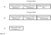
- FIG. 12 shows a schematic diagram of a broadcast signal arranged in a broadcast time slot according to an embodiment.
- the broadcast signal comprises a plurality of broadcast signal sections, each broadcast signal section being associated with a transmission slot in the predetermined transmission interval.
- a first transmission time slot is assigned to a first detection device
- a second transmission time slot is assigned to a second detection device
- a third transmission time slot is free.
- a third detection device is added and occupies the free third transmit slot to communicate data to the server entity.
- Diagram b) shows an allocation of the transmission time slots by the broadcast signal in a subsequent broadcast phase.
- the broadcast signal indicates a new assignment of the transmission time slots, wherein the third transmission time slot of the third detection device is now permanently assigned.
- the assignment or allocation of the transmission time slots can be done, for example, by specifying an identity identifier or a network address of the respective detection device in the respective broadcast signal section.
- an optional indication of an actual occupancy of the transmission time slots is shown, wherein the indication additionally takes place in the broadcast time slot.
- the server entity per transmit slot may indicate a ratio of transmit intervals and actual busy transmit slots.
- FIG. 12 is a schematic diagram of a communication system 400 according to an embodiment.
- the communication system 400 includes a plurality of detection device groups 200 and a plurality of server entities 300.
- the plurality of detection device detection devices 200 may communicate with the plurality of server entities 300 via a communication network 401.
- the groups 200 each comprise detection devices. Each group 200 is associated with an associated server entity 300.
- the server entities 300 may synchronize with each other regarding the idle and / or busy transmit time slots using time slot allocation signals. In this way further collisions in the communication over the communication network 401 are avoided.
- the transmission medium is used efficiently in terms of time diversity. This will further increase system capacity.
- the server entities 300 may exchange and allocate each other using idle and / or busy transmit timeslots using the timeslot allocation signals.
- FIG. 12 is a schematic diagram of a communication system 400 according to an embodiment.
- the communication system 400 includes a plurality of detection device groups 200 and a plurality of server entities 300.
- the plurality of detection device detection devices 200 may communicate with the plurality of server entities 300 via a communication network 401.
- the communication network 401 includes a plurality of subnetworks. Each group 200 is associated with a respective server entity 300 to a respective subnetwork.
- the communication network 401 may be a fifth generation (5G) or another generation communication network, each subnetwork being associated with a slice of the communication network 401.
- the communication between the Server entities 300 may be managed in a slice management layer which may be above the infrastructure layer.
- Fig. 13 shows a schematic diagram of a signal format for transmitting data with an identity identifier of a detection device.
- the signal format also indicates a periodicity for broadcasting data at transmission intervals.
- the periodicity can be indicated by values. For example, a value of 0 may indicate that no periodicity, i. a one-time sending of data.
- the one-time sending can be event-controlled. For example, a value of 1 may indicate that it should be sent once in a transmission interval. For example, a value of 2 may indicate that it should be sent twice in a transmission interval. For example, a value of 4 may indicate that four times in a transmission interval should be sent out. For example, a value of X may indicate that you want to send out X times in one send interval.
- Fig. 14 shows a schematic diagram of a predetermined transmission interval with transmission time slots TS 0 to TS 7.
- the outer annulus shows signals in the uplink (uplink).
- the inner annulus shows signals, in particular broadcast signals, in the downlink direction.
- the signals are off according to the signal format Fig. 13 formatted.
- the detection devices may be in a receive mode unless they are transmitting data.
- the reception of the data can be confirmed in the downward direction immediately after the corresponding transmission time slot by the server entity.
- the detection devices can always be in a receiving mode.
- the detection devices may generate and manage a table indicating busy and idle transmission timeslots. If there is no acknowledgment by the server entity for a transmission slot over several transmission intervals, the detection devices may again regard the transmission slot as available or unused.
- Fig. 15 shows a schematic diagram of a predetermined transmission interval with transmission time slots TS 0 to TS 7.
- the outer annulus shows signals in the uplink (uplink).
- the inner annulus shows signals, in particular broadcast signals, in Downlink.
- the signals are off according to the signal format Fig. 13 formatted.
- transmission time slot TS 1 a detection device with identity code 101 which had sent in transmission time slot TS 0 was indicated that the data was successfully received by the server entity. All other detection devices were thus indicated that the previous transmission time slot TS 0 was just assigned once and can be regarded as unoccupied in the following transmission interval.
- transmission time slot TS 3 a detection device with identity code 104 which had sent in transmission time slot TS 2 was indicated that the data was successfully received by the server entity. All other detection devices were thus indicated that the previous transmission time slot TS 2 is assigned in each transmission interval and can be considered occupied in the following transmission interval.
- transmission time slot TS 6 a detection device with identity ID 123 which had sent in transmission time slot TS 5 was indicated that the data was successfully received by the server entity. All other detection devices were thus indicated that the previous transmission time slot TS 5 is assigned in each transmission interval and can be regarded as busy in the following transmission interval. Further, the detection device with identity identifier 123, for example, transmit data in transmission time slot TS 1, whereby a further transmission time slot can be occupied according to the displayed periodicity with two transmission time slots in each transmission interval.
Landscapes
- Engineering & Computer Science (AREA)
- Computer Networks & Wireless Communication (AREA)
- Signal Processing (AREA)
- Health & Medical Sciences (AREA)
- Computing Systems (AREA)
- General Health & Medical Sciences (AREA)
- Medical Informatics (AREA)
- Mobile Radio Communication Systems (AREA)
Priority Applications (3)
| Application Number | Priority Date | Filing Date | Title |
|---|---|---|---|
| EP16179539.8A EP3270571A1 (fr) | 2016-07-14 | 2016-07-14 | Dispositif de detection d'une grandeur physique |
| PCT/EP2017/067286 WO2018011147A1 (fr) | 2016-07-14 | 2017-07-10 | Dispositif de détection servant à la détection d'une grandeur physique |
| EP17735585.6A EP3485631B1 (fr) | 2016-07-14 | 2017-07-10 | Dispositif, procédé et programme informatique pour la detection d'une grandeur physique et serveur pour attribuer un interval de temps de transmission |
Applications Claiming Priority (1)
| Application Number | Priority Date | Filing Date | Title |
|---|---|---|---|
| EP16179539.8A EP3270571A1 (fr) | 2016-07-14 | 2016-07-14 | Dispositif de detection d'une grandeur physique |
Publications (1)
| Publication Number | Publication Date |
|---|---|
| EP3270571A1 true EP3270571A1 (fr) | 2018-01-17 |
Family
ID=56557491
Family Applications (2)
| Application Number | Title | Priority Date | Filing Date |
|---|---|---|---|
| EP16179539.8A Withdrawn EP3270571A1 (fr) | 2016-07-14 | 2016-07-14 | Dispositif de detection d'une grandeur physique |
| EP17735585.6A Active EP3485631B1 (fr) | 2016-07-14 | 2017-07-10 | Dispositif, procédé et programme informatique pour la detection d'une grandeur physique et serveur pour attribuer un interval de temps de transmission |
Family Applications After (1)
| Application Number | Title | Priority Date | Filing Date |
|---|---|---|---|
| EP17735585.6A Active EP3485631B1 (fr) | 2016-07-14 | 2017-07-10 | Dispositif, procédé et programme informatique pour la detection d'une grandeur physique et serveur pour attribuer un interval de temps de transmission |
Country Status (2)
| Country | Link |
|---|---|
| EP (2) | EP3270571A1 (fr) |
| WO (1) | WO2018011147A1 (fr) |
Citations (1)
| Publication number | Priority date | Publication date | Assignee | Title |
|---|---|---|---|---|
| US20150341874A1 (en) * | 2014-03-18 | 2015-11-26 | Smartrek Technologies Inc. | Mesh Network System and Techniques |
-
2016
- 2016-07-14 EP EP16179539.8A patent/EP3270571A1/fr not_active Withdrawn
-
2017
- 2017-07-10 EP EP17735585.6A patent/EP3485631B1/fr active Active
- 2017-07-10 WO PCT/EP2017/067286 patent/WO2018011147A1/fr unknown
Patent Citations (1)
| Publication number | Priority date | Publication date | Assignee | Title |
|---|---|---|---|---|
| US20150341874A1 (en) * | 2014-03-18 | 2015-11-26 | Smartrek Technologies Inc. | Mesh Network System and Techniques |
Non-Patent Citations (1)
| Title |
|---|
| ACHIM BERGER ET AL: "TDMA approach for efficient data collection in wireless sensor networks", MECHATRONICS (ICM), 2011 IEEE INTERNATIONAL CONFERENCE ON, IEEE, 13 April 2011 (2011-04-13), pages 755 - 760, XP031911235, ISBN: 978-1-61284-982-9, DOI: 10.1109/ICMECH.2011.5971215 * |
Also Published As
| Publication number | Publication date |
|---|---|
| EP3485631A1 (fr) | 2019-05-22 |
| WO2018011147A1 (fr) | 2018-01-18 |
| EP3485631B1 (fr) | 2021-09-22 |
Similar Documents
| Publication | Publication Date | Title |
|---|---|---|
| EP2016527B1 (fr) | Procédé permettant de faire fonctionner un réseau RFID | |
| DE69920634T2 (de) | Verfahren zur Konkurrenzbetriebsauflösung in einem mobilen Übertragungssystem | |
| EP2227920B1 (fr) | Réseau de communication auto-organisé et son procédé de fonctionnement | |
| DE69934656T2 (de) | Drahtloses Zugangsverfahren bei dem die Kontrollinformation mehrmals und im voraus übertragen wird. | |
| DE60011689T2 (de) | Funkkommunikation in einem lokalen Netzwerk | |
| EP0006594B1 (fr) | Procédé hyperbolique de comparaison de phase pour la détermination de la position de véhicules dans une zone donnée et dispositif pour la mise en oeuvre dudit procédé | |
| EP3270603B1 (fr) | Dispositif de détection d'une grandeur physique | |
| DE102013105032B4 (de) | Kommunikationsnetzwerkvorrichtung, Basisstation und Drahtloskommunikationsvorrichtung | |
| EP2365711A1 (fr) | Réseau sans fil, notamment pour applications d'automatisation, en temps réel et/ou industrielles | |
| EP2805185B1 (fr) | Procédé pour faire fonctionner un appareil de terrain, appareil de terrain, et serveur pour un réseau d'automatisation de grande surface | |
| EP3439253B1 (fr) | Procédé de commande d'accès multimédia et système antiaérien tactique | |
| DE102011081269A1 (de) | Verfahren zur Netzwerkorganisation | |
| EP3949682B1 (fr) | Combinaison de système d'un système radio asynchrone et synchrone | |
| EP3485631B1 (fr) | Dispositif, procédé et programme informatique pour la detection d'une grandeur physique et serveur pour attribuer un interval de temps de transmission | |
| EP3313051B1 (fr) | Procédé d'attribution d'adresse pour une pluralité de compteurs de mesure destinés au comptage ainsi que système comportant la passerelle, l'adaptateur maître et l'adaptateur d'esclave | |
| DE112020003813T5 (de) | Verfahren und vorrichtung zur aperiodischen datenübertragung bei sidelink-kommunikation | |
| EP1180909B1 (fr) | Méthode et dispositif pour l'acquisition de données | |
| DE102005036255A1 (de) | Datenübertragungssystem und Verfahren zum Betreiben eines Datenübertragungssystems | |
| WO2018011144A1 (fr) | Dispositif conçu pour la détection d'une grandeur physique | |
| WO2018011146A1 (fr) | Dispositif conçu pour la détection d'une grandeur physique | |
| DE19510280A1 (de) | Austauschprotokoll für digitale Daten | |
| EP1139607B1 (fr) | Réseau sans fil avec un mécanisme de triage d'intervalles de temps | |
| EP3513500B1 (fr) | Synchronisation de noeuds de transmission | |
| DE102012208645A1 (de) | Verfahren zum Betreiben einer stationären Einrichtung sowie stationäre Einrichtung innerhalb eines Systems zur Kommunikation | |
| AT15998U1 (de) | Synchronisation von Übertragungsknoten |
Legal Events
| Date | Code | Title | Description |
|---|---|---|---|
| PUAI | Public reference made under article 153(3) epc to a published international application that has entered the european phase |
Free format text: ORIGINAL CODE: 0009012 |
|
| STAA | Information on the status of an ep patent application or granted ep patent |
Free format text: STATUS: THE APPLICATION HAS BEEN PUBLISHED |
|
| AK | Designated contracting states |
Kind code of ref document: A1 Designated state(s): AL AT BE BG CH CY CZ DE DK EE ES FI FR GB GR HR HU IE IS IT LI LT LU LV MC MK MT NL NO PL PT RO RS SE SI SK SM TR |
|
| AX | Request for extension of the european patent |
Extension state: BA ME |
|
| STAA | Information on the status of an ep patent application or granted ep patent |
Free format text: STATUS: THE APPLICATION IS DEEMED TO BE WITHDRAWN |
|
| 18D | Application deemed to be withdrawn |
Effective date: 20180718 |