EP3270571A1 - Detection device to detect a physical quantity - Google Patents
Detection device to detect a physical quantity Download PDFInfo
- Publication number
- EP3270571A1 EP3270571A1 EP16179539.8A EP16179539A EP3270571A1 EP 3270571 A1 EP3270571 A1 EP 3270571A1 EP 16179539 A EP16179539 A EP 16179539A EP 3270571 A1 EP3270571 A1 EP 3270571A1
- Authority
- EP
- European Patent Office
- Prior art keywords
- detection device
- transmission time
- time slot
- group
- server entity
- Prior art date
- Legal status (The legal status is an assumption and is not a legal conclusion. Google has not performed a legal analysis and makes no representation as to the accuracy of the status listed.)
- Withdrawn
Links
- 238000001514 detection method Methods 0.000 title claims abstract description 267
- 230000005540 biological transmission Effects 0.000 claims abstract description 313
- 238000004891 communication Methods 0.000 claims abstract description 192
- 238000000034 method Methods 0.000 claims description 22
- 230000001133 acceleration Effects 0.000 claims description 4
- 238000004590 computer program Methods 0.000 claims description 2
- 239000000446 fuel Substances 0.000 claims description 2
- XLYOFNOQVPJJNP-UHFFFAOYSA-N water Substances O XLYOFNOQVPJJNP-UHFFFAOYSA-N 0.000 claims description 2
- 238000010586 diagram Methods 0.000 description 35
- 238000005516 engineering process Methods 0.000 description 5
- 238000005265 energy consumption Methods 0.000 description 2
- 238000010438 heat treatment Methods 0.000 description 2
- 238000004519 manufacturing process Methods 0.000 description 2
- 238000012544 monitoring process Methods 0.000 description 2
- 238000013459 approach Methods 0.000 description 1
- 230000001419 dependent effect Effects 0.000 description 1
- 230000006855 networking Effects 0.000 description 1
- 230000001105 regulatory effect Effects 0.000 description 1
- 230000002618 waking effect Effects 0.000 description 1
Images


Classifications
-
- H—ELECTRICITY
- H04—ELECTRIC COMMUNICATION TECHNIQUE
- H04L—TRANSMISSION OF DIGITAL INFORMATION, e.g. TELEGRAPHIC COMMUNICATION
- H04L67/00—Network arrangements or protocols for supporting network services or applications
- H04L67/01—Protocols
- H04L67/12—Protocols specially adapted for proprietary or special-purpose networking environments, e.g. medical networks, sensor networks, networks in vehicles or remote metering networks
- H04L67/125—Protocols specially adapted for proprietary or special-purpose networking environments, e.g. medical networks, sensor networks, networks in vehicles or remote metering networks involving control of end-device applications over a network
-
- H—ELECTRICITY
- H04—ELECTRIC COMMUNICATION TECHNIQUE
- H04L—TRANSMISSION OF DIGITAL INFORMATION, e.g. TELEGRAPHIC COMMUNICATION
- H04L67/00—Network arrangements or protocols for supporting network services or applications
- H04L67/50—Network services
- H04L67/60—Scheduling or organising the servicing of application requests, e.g. requests for application data transmissions using the analysis and optimisation of the required network resources
- H04L67/62—Establishing a time schedule for servicing the requests
Definitions
- the present invention relates to the field of physical quantity detection and the transmission of data representing the physical quantity over a communication network.
- the term Internet of Things is understood to mean the networking of physical objects via a communication network, which enables, for example, a more efficient monitoring of the physical objects and an exchange of information about the physical objects.
- the Internet of Things is of increasing importance especially in the field of home automation technology and industrial automation technology, wherein different physical quantities, such as a temperature or an energy consumption, are to be detected efficiently.
- heating sensors for billing heating costs are increasingly being equipped with appropriate functionality.
- production processes are to be optimized and carried out more efficiently. Appropriate approaches for this are mostly summarized under the term Industry 4.0.
- the present invention is based on the finding that the above object can be achieved by a detection device to which an identity identifier is assigned and which is designed to receive a broadcast signal from a server entity via a communication network.
- the detection device can be assigned to a group of detection devices, wherein each detection device of the group can communicate with the server entity and receive the broadcast signal.
- the broadcast signal may indicate an occupancy of transmission time slots in a predetermined transmission interval by assigning identity identifiers of the detection devices to transmission time slots.
- the detection device is configured to select a free transmission time slot of the predetermined transmission interval if no transmission time slot is assigned to the identity identifier of the detection device, and to send data in the selected transmission time slot to the server entity via the communication network.
- the detection device can also be designed to select an occupied transmission time slot of the predetermined transmission interval if the assigned transmission time slot is assigned the identity identifier of the detection device.
- Each detection device of the group can therefore independently select and occupy a free transmission time slot in the predetermined transmission interval.
- the server entity can thereupon permanently assign the respective transmission time slot of the respective detection device by assigning the respective identity identifier to the respective transmission time slot.
- the respective detection device can use the now permanently assigned transmission time slot for transmitting data.
- the transmission intervals with the respective transmission time slots can be repeated periodically.
- the invention relates to a detection device for detecting a physical quantity, wherein the detection device of a group of Associated detection devices, wherein each detection device of the group of detection devices is associated with an identity identifier, wherein the group of detection devices is adapted to communicate over a communication network with a server entity, with a detector for detecting the physical size, wherein the detector is configured to output data representing the physical quantity and a communication interface configured to receive a broadcast signal from the server entity via the communication network, the broadcast signal indicating an occupancy of transmission time slots in a predetermined transmission interval by assigning identity identifiers from detection devices to transmission time slots, the communication interface is configured to select a free transmission time slot of the predetermined transmission interval, if no transmission time slot de identity identifier de r is associated with the detection device, and wherein the communication interface is adapted to transmit the data in the selected transmission time slot over the communication network to the server entity.
- the identity identifier of the detection device can be assigned permanently to the detection device during its production.
- the identity identifier may be, for example, a Media Access Control (MAC) address or an International Mobile Station Equipment Identity (IMEI) number associated with the detection device.
- MAC Media Access Control
- IMEI International Mobile Station Equipment Identity
- the communication interface is designed to select an occupied transmission time slot of the predetermined transmission interval if the occupied transmission time slot is assigned the identity identifier of the detection device.
- the broadcast signal comprises a plurality of broadcast signal sections, each broadcast signal section being associated with a transmission slot in the predetermined transmission interval, and wherein the communication interface is configured to extract the plurality of broadcast signal sections from the broadcast signal.
- a free transmission time slot in the predetermined transmission interval may be indicated by a respective empty broadcast signal portion.
- An occupied transmission time slot in the predetermined transmission interval may be indicated, for example, by the display of an identity identifier in the respective broadcast signal portion.
- the broadcast signal having the broadcast signal portions may be arranged in a broadcast time slot.
- the detector is designed to link the data with the identity identifier of the detection device, wherein the communication interface is designed to transmit the data with the identity identifier of the detection device in the selected transmission time slot.
- the broadcast signal indicates an amount of data received by the server entity in a transmission slot over the communication network, the communication interface configured to compare the amount to a reference set.
- the detector is configured to compare the detected physical quantity with a predetermined physical reference size, wherein the communication interface is adapted to transmit the data in the selected transmit time slot if the detected physical quantity exceeds the predetermined physical reference size.
- the detector is configured to include temperature, humidity, energy, power, position, velocity, acceleration, angle, angular velocity, angular acceleration, speed, force, torque, energy consumption, a water consumption, a heat consumption or a fuel consumption as physical To determine size.
- the detector may for this purpose comprise a sensor for determining the physical quantity.
- the detection device comprises a timer, in particular a real-time clock, for providing a time signal, wherein the time signal indicates a time difference between a current time and a predetermined reference time, and wherein the communication interface is configured, a beginning of the selected transmission time slot on the basis of the time signal to determine.
- the communication interface is configured to receive a time synchronization signal from the server entity via the communication network, and wherein the timer is configured to change the time signal based on the received time synchronization signal.
- the timer comprises a satellite navigation receiver, in particular a GPS satellite navigation receiver or a GALILEO satellite navigation receiver, wherein the satellite navigation receiver is adapted to provide a time synchronization signal, and wherein the timer is adapted to change the time signal based on the provided time synchronization signal.
- the timer comprises a time signal receiver, in particular a DCF77 receiver, wherein the time signal receiver is configured to provide a time synchronization signal, and wherein the timer is configured to change the time signal on the basis of the provided time synchronization signal.
- the identity identifier of the detection device is a network address of the detection device.
- the network address can be assigned to the detection device, for example, by the server entity via the communication network.
- the network address of the detection device may be an Internet Protocol (IP) address, such as an IPv4 address or an IPv6 address.
- IP Internet Protocol
- the communication network comprises a plurality of subnetworks, wherein the communication interface is configured to transmit the data via a subnetwork of the plurality of subnetworks.
- the communication network is a fifth generation (5G) or another generation communication network, each subnetwork being a slice of the communication network.
- 5G fifth generation
- This provides the advantage that efficient transmission of the data can be realized over a fifth generation (5G) communication network or another generation.
- the invention relates to a group of detection devices, wherein each detection device is associated with a transmission time slot in a predetermined transmission interval for transmitting data, and wherein the transmission time slots are different.
- the invention relates to a server entity for assigning a transmission time slot of a predetermined transmission interval to a detection device of a group of detection devices for communication via a communication network, having a communication interface, which is designed to transmit a broadcast signal to the detection device, wherein the broadcast signal occupies an occupancy of transmission time slots in the predetermined transmission interval by assigning identity identifiers from detection devices to transmission time slots, wherein the predetermined transmission interval has at least one free transmission time slot to which no identity identifier is assigned, the communication interface being configured to receive data from the detection device in the free transmission time slot and a processor configured to associate the free transmission time slot with the detection device.
- the server entity may be configured to manage free transmit time slots and / or busy transmit time slots of a plurality of detection devices.
- the server entity may be a base station, wherein the base station is configured to communicate with the detection device via a radio communication network as a communication network.
- the server entity may also be a controller, wherein the controller is associated with a backhaul network of the communication network.
- the processor is configured to generate a further broadcast signal, wherein the further broadcast signal indicates an assignment of the identity identifier of the detection device to the free transmit time slot, and wherein the communication interface is configured to send the further broadcast signal to the detection device.
- the free transmission time slot is therefore displayed to the detection device as an occupied transmission time slot in a subsequent transmission interval to which the identity identifier of the detection device is assigned.
- the server entity comprises a timer, in particular a real-time clock, for providing a time signal, the time signal indicating a time difference between a current time and a predetermined reference time, the processor configured to generate a time synchronization signal based on the time signal, and wherein the communication interface is adapted to transmit the time synchronization signal to the detection device via the communication network.
- the communication interface is configured to receive a time slot occupancy signal from another server entity via the communication network, the time slot occupancy signal indicating an occupied transmit time slot in the predetermined transmit interval, and wherein the processor is configured to transmit the broadcast signal and / or the further broadcast signal on the base of the time slot allocation signal.
- the processor is configured to determine an occupied transmission time slot in the predetermined transmission interval and to generate a time slot allocation signal for transmission to another server entity, the time slot occupation signal indicating the occupied transmission time slot in the predetermined transmission interval, and wherein the communication interface is formed Time slot allocation signal to send the further server entity via the communication network.
- the invention relates to a communication system comprising a group of detection devices, wherein each detection device of the group is assigned a transmission time slot in a predetermined transmission interval for transmitting data, and wherein the transmission time slots are different, and a server entity which is formed each Detection device of the group to assign a transmission time slot in the predetermined transmission interval.
- each detection device of the group is designed to send the data in each case to the server entity via the communication network. This provides the advantage that the data can be efficiently evaluated and stored by the server entity.
- the communication system comprises a further group of detection devices, wherein each detection device of the further group is assigned a transmission time slot in the predetermined transmission interval or in another transmission interval for transmitting data, and wherein the transmission time slots are different, and another server entity, which is formed is, every detection device assign the further group a transmission time slot in the predetermined transmission interval or in the further transmission interval.
- the server entity and the further server entity can communicate with each other via the communication network.
- the server entity and the further server entity can exchange slot allocation signals with each other.
- the transmission interval and the further transmission interval follow one another in time.
- each detection device of the further group is designed to send the data in each case to the further server entity via the communication network. This provides the advantage that the data can be efficiently evaluated and stored by the further server entity.
- the free transmission time slots of the group of detection devices each have a transmission time slot duration, wherein the free transmission time slots of the further group of detection devices each have a further transmission time slot duration, and wherein the transmission time slot duration and the further transmission time slot duration are different.
- the communication network is a fifth generation (5G) or a further generation communication network, the communication network comprising a subnetwork, in particular a slice, and a further subnetwork, in particular a further slice, wherein the group of detection devices and the server entity correspond to the one Subnetwork are assigned, and wherein the further group of detection devices and the further server entity are assigned to the other subnetwork.
- 5G fifth generation
- the communication network comprising a subnetwork, in particular a slice, and a further subnetwork, in particular a further slice, wherein the group of detection devices and the server entity correspond to the one Subnetwork are assigned, and wherein the further group of detection devices and the further server entity are assigned to the other subnetwork.
- the invention relates to a method for detecting a physical quantity using a detection device, wherein the Detection device comprises a detector and a communication interface, wherein the detection device is associated with a group of detection devices, each detection device of the group of detection devices is associated with an identity identifier, wherein the group of detection devices is configured to communicate over a communication network with a server entity, with a detecting the physical quantity by the detector, outputting by the detector representing data the physical quantity, receiving a broadcasting signal from the server entity via the communication network through the communication interface, the broadcasting signal occupying a transmission time slots in a predetermined transmission interval by assigning identity identifiers from detection devices to transmission time slots, selecting a free transmission time slot of the predetermined transmission interval Alls by the communication interface, if no transmission time slot is assigned the identity identifier of the detection device, and sending out the data in the selected transmission time slot over the communication network to the server entity through the communication interface.
- the method may be performed by the detection device. Further features of the method emerge directly from the functionality and / or the features of the detection device.
- the invention relates to a method for assigning a transmission time slot of a predetermined transmission interval to a detection device of a group of detection devices for communication via a communication network using a server entity, the server entity comprising a communication interface and a processor, with a broadcasting of a broadcast signal the detection device through the communication interface, the broadcast signal indicating an occupancy of transmission time slots in the predetermined transmission interval by assigning identity identifiers from detection devices to transmission time slots, the predetermined transmission interval having at least one free transmission time slot to which no identity identifier is assigned, receiving data from the detection device in the free transmission time slot through the communication interface, and assigning the free Se Time slot to the detection device by the processor.
- the method may be performed by the server entity. Further features of the method result directly from the functionality and / or the features of the server entity.
- the invention relates to a computer program having a program code for carrying out the method for detecting a physical quantity or the method for allocating a transmission time slot when the program code is executed on a computer. This provides the advantage that the methods can be carried out automatically.
- the detection device and / or the server entity may be program-programmed to execute the program code.
- the invention can be implemented in hardware and / or in software.
- FIG. 12 shows a schematic diagram of a physical quantity detecting apparatus 100 according to an embodiment.
- the detection device 100 is assigned to a group of detection devices 100, wherein each detection device 100 of the group of detection devices 100 is assigned an identification code.
- the group of detection devices 100 is configured to communicate with a server entity over a communication network.
- the detection device 100 comprises a detector 101 for detecting the physical quantity, wherein the detector 101 is designed to output data representing the physical quantity.
- the detection device 100 further comprises a communication interface 103, which is configured to receive a broadcast signal from the server entity via the communication network, the broadcast signal indicating an occupancy of transmission time slots in a predetermined transmission interval by assignment of identity identifiers from detection devices to transmission time slots.
- the communication interface 103 is configured to select a free transmission time slot of the predetermined transmission interval if no transmission time slot is assigned to the identity identifier of the detection device.
- the communication interface 103 is further configured to send the data in the selected transmission time slot over the communication network to the server entity.
- the detection device 100 may further comprise a timer, in particular a real-time clock, for providing a time signal.
- the time signal indicates a time difference between a present time and a predetermined reference time.
- the communication interface 103 is configured to determine a beginning of the selected transmission time slot on the basis of the time signal.
- FIG. 12 shows a schematic diagram of a group 200 of physical quantity detecting devices 100 according to an embodiment.
- Each detection device 100 is assigned in each case an identity identifier.
- Each detection device 100 comprises in each case a detector 101 and a communication interface 103.
- Each detection device 100 is assigned a transmission time slot in a predetermined transmission interval for transmitting data. The transmission time slots are different.
- FIG. 12 shows a schematic diagram of a server entity 300 according to an embodiment.
- the server entity 300 is configured to transmit a transmission time slot of a predetermined transmission interval to a detection device of a group of Assign detection devices for communication over a communication network.
- the server entity 300 comprises a communication interface 301, which is configured to transmit a broadcast signal to the detection device, the broadcast signal indicating an occupancy of transmission time slots in the predetermined transmission interval by assignment of identity identifiers from detection devices to transmission time slots, the predetermined transmission interval having at least one free transmission time slot, to which no identity identifier is assigned.
- the communication interface 301 is further configured to receive data from the detection device in the free transmit time slot.
- Server entity 300 further includes a processor 303 configured to associate the free transmit time slot with the detection device.
- the processor 303 may be configured to generate a further broadcast signal, wherein the further broadcast signal indicates an assignment of the identity identifier of the detection device to the free transmission time slot.
- the communication interface 301 may be configured to send the further broadcast signal to the detection device.
- FIG. 12 is a schematic diagram of a communication system 400 according to an embodiment.
- the communication system 400 comprises a group 200 of detection devices 100, wherein each detection device 100 of the group 200 is assigned a transmission time slot in a predetermined transmission interval for transmitting data, and wherein the transmission time slots are different.
- the communication system 400 further comprises a server entity 300, which is configured to associate with each detection device 100 of the group 200 a transmission time slot in the predetermined transmission interval.
- the group 200 of detection devices 100 may communicate with the server entity 300 via a communication network 401.
- FIG. 12 shows a schematic diagram of a method 500 for detecting a physical quantity using a detection device according to one embodiment.
- the detection device comprises a detector and a communication interface.
- the detection device is assigned to a group of detection devices, wherein each detection device is assigned to the group of detection devices an identity identifier.
- the group of detection devices is configured to communicate with a server entity via a communication network.
- the method 500 includes detecting by the detector 501 the physical quantity, outputting 503 data representing the physical quantity by the detector, receiving 505 a broadcast signal from the server entity via the communication network through the communication interface, wherein the broadcast signal is occupied by Indicates transmission time slots in a predetermined transmission interval by assigning identity identifiers from detection devices to transmission time slots, selecting 507 a free transmission time slot of the predetermined transmission interval through the communication interface if no transmission time slot is associated with the identity identifier of the detection device, and transmitting 509 the data in the selected transmission time slot over the communication time slot Communication network to the server entity through the communication interface.
- FIG. 12 shows a schematic diagram of a method 600 for assigning a transmission time slot of a predetermined transmission interval to a detection device of a group of detection devices for communication over a communication network using a server entity according to an embodiment.
- the server entity includes a communication interface and a processor.
- the method 600 comprises transmitting 601 a broadcast signal to the detection device through the communication interface, the broadcast signal indicating an occupancy of transmission time slots in the predetermined transmission interval by assigning identity identifiers from detection devices to transmission time slots, the predetermined transmission interval having at least one free transmission time slot which does not have an identity identifier a receiving 603 of data from the detection device in the free transmission time slot by the communication interface, and assigning 605 of the free transmission time slot to the detection device by the processor.
- FIG. 12 shows a schematic diagram of a physical quantity detecting apparatus 100 according to an embodiment.
- the detection device 100 is assigned to a group of detection devices 100, wherein each detection device 100 of the group of detection devices 100 is assigned an identification code.
- the group of detection devices 100 is configured to communicate with a server entity via a communication network 401.
- the detection device 100 comprises a detector 101 for detecting the physical quantity, wherein the detector 101 is designed to output data representing the physical quantity.
- the detection device 100 further comprises a communication interface 103, which is configured to receive a broadcast signal from the server entity via the communication network 401, the broadcast signal indicating an occupancy of transmission time slots in a predetermined transmission interval by assignment of identity identifiers from detection devices to transmission time slots.
- the communication interface 103 is configured to select a free transmission time slot of the predetermined transmission interval if no transmission time slot is assigned to the identity identifier of the detection device.
- the communication interface 103 is further configured to transmit the data in the selected transmission time slot via the communication network 401 to the server entity.
- FIG. 12 is a schematic diagram of a communication system 400 according to an embodiment.
- the communication system 400 comprises a group 200 of detection devices 100, wherein each detection device 100 of the group 200 is assigned a transmission time slot in a predetermined transmission interval for transmitting data, and wherein the transmission time slots are different.
- the communication system 400 further comprises a server entity 300, which is configured to associate with each detection device 100 of the group 200 a transmission time slot in the predetermined transmission interval.
- the group 200 of detection devices 100 may communicate with the server entity 300 via a communication network 401.
- the server entity 300 is configured to send a broadcast signal to the detection devices 100 of the group 200.
- the predetermined transmission interval comprises three transmission time slots ZI, ZII and ZIII, wherein the transmission time slot ZI is assigned to the first detection device 100, the transmission time slot ZII being assigned to the second detection device 100, and the transmission time slot ZIII being occupied by the third detection device 100.
- the server entity 300 which may be a base station or a controller, sends in a broadcast time slot 0 by broadcast signal to the detection devices 100 of the group 200 an indication of transmission time slots in a subsequent transmission interval in which the detection devices 100 transmit their data to the server entity 300 can.
- the broadcast time slot 0 for example, the already made occupancy of the transmission time slots by existing detection devices 100 is mentioned.
- the second detection device 100 is assigned the transmission time slot ZII.
- a detection device 100 If a detection device 100 is added, for example after waking up from a rest state, it can transmit data in a free transmission time slot, for example transmission time slot ZV, to the server entity 300. This then sends in the subsequent broadcast signal in the broadcast time slot 0, the fixed assignment of the newly added detection device 100 to the transmission time slot ZV. As a result, the transmission time slots are assigned to the detection devices 100 of the group 200 successively.
- a free transmission time slot for example transmission time slot ZV
- the broadcast signal can also transmit for each transmission time slot, and therefore also for each detection device 100 of the group 200, which is assigned to a transmission time slot, further information to the detection devices 100.
- a sequence number can be transmitted for each transmission time slot.
- an indication of the occupancy of the transmission time slots by the detection devices 100 can be displayed.
- a set of data in particular a number of received data packets, can be displayed for the respective transmission time slots.
- an actual occupancy per number of transmission intervals can be displayed for each transmission time slot. In this way it can be determined, for example, whether a detection device 100 transmits data in a specific transmission time slot in each transmission interval or in every xth transmission interval, for example every second transmission interval. This information can be transmitted by broadcast signal to all detection devices 100 of the group 200. The detection devices 100 can thereby dynamically occupy the unused transmission timeslots assigned to another detection device 100.
- the server entity 300 may, for example, specify a time sharing of the transmission time slots between two detection devices 100, after which the detection devices 100, for example, transmit data alternately in the same transmission time slot of a plurality of transmission intervals. This achieves an improved allocation of resources.
- the server entity 300 in the broadcast time slot 0 can also transmit control signals to the detection devices 100 of the group 200, for example to grant an approval that the detection devices 100 can autonomously occupy free and / or unoccupied transmission time slots as required.
- the detection devices 100 can also decide themselves whether they transmit their data in the transmission time slots only to the server entity 300 or also by broadcast to all detection devices 100 of the same group 200.
- the detection devices 100 of the group 200 can be set to receive in the transmission time slots not assigned to them.
- the communication between each group 100 detection device 100 and server entity 300 may be narrowband, i. done with very low data rate.
- the communication network 401 may be a wireless communication network or a wired communication network.
- the communication may be made using an IEEE 802.11 wireless local area network (WLAN), an IEEE 802.15.1 (Bluetooth) communication standard, a DSL communication standard, or a 3GPP communication standard.
- the communication may be performed using a fifth generation (5G) or another generation mobile radio standard.
- 5G fifth generation
- the communication system 400 can be implemented inexpensively. At the same time, collisions of the data on the communication channel can be avoided.
- the communication system 400 enables a high volume data rate, whereby a high number of detection devices can be supported.
- a communication channel For communication via the communication network 401 can be dispensed with a return channel. Further are No acknowledgment (ACKs) required.
- ACKs acknowledgment
- a simple modulation for example an amplitude modulation or a phase modulation, can be used.
- FIG. 12 is a schematic diagram of a transmit interval having a plurality of transmit time slots according to an embodiment.
- the diagram shows a transmission interval which comprises a transmission time slot I, a transmission time slot II and a transmission time slot III, the detection devices of the group transmitting data in the transmission time slots in each case.
- the diagram also shows a broadcast time slot 0 in which the broadcast signal is arranged.
- the server entity which may be a controller, broadcasts the broadcast signal.
- the detection devices send their data to the server entity respectively.
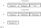
- FIG. 12 shows a schematic diagram of a broadcast signal arranged in a broadcast time slot according to an embodiment.
- the broadcast signal comprises a plurality of broadcast signal sections, each broadcast signal section being associated with a transmission slot in the predetermined transmission interval.
- a first transmission time slot is assigned to a first detection device
- a second transmission time slot is assigned to a second detection device
- a third transmission time slot is free.
- a third detection device is added and occupies the free third transmit slot to communicate data to the server entity.
- Diagram b) shows an allocation of the transmission time slots by the broadcast signal in a subsequent broadcast phase.
- the broadcast signal indicates a new assignment of the transmission time slots, wherein the third transmission time slot of the third detection device is now permanently assigned.
- the assignment or allocation of the transmission time slots can be done, for example, by specifying an identity identifier or a network address of the respective detection device in the respective broadcast signal section.
- an optional indication of an actual occupancy of the transmission time slots is shown, wherein the indication additionally takes place in the broadcast time slot.
- the server entity per transmit slot may indicate a ratio of transmit intervals and actual busy transmit slots.
- FIG. 12 is a schematic diagram of a communication system 400 according to an embodiment.
- the communication system 400 includes a plurality of detection device groups 200 and a plurality of server entities 300.
- the plurality of detection device detection devices 200 may communicate with the plurality of server entities 300 via a communication network 401.
- the groups 200 each comprise detection devices. Each group 200 is associated with an associated server entity 300.
- the server entities 300 may synchronize with each other regarding the idle and / or busy transmit time slots using time slot allocation signals. In this way further collisions in the communication over the communication network 401 are avoided.
- the transmission medium is used efficiently in terms of time diversity. This will further increase system capacity.
- the server entities 300 may exchange and allocate each other using idle and / or busy transmit timeslots using the timeslot allocation signals.
- FIG. 12 is a schematic diagram of a communication system 400 according to an embodiment.
- the communication system 400 includes a plurality of detection device groups 200 and a plurality of server entities 300.
- the plurality of detection device detection devices 200 may communicate with the plurality of server entities 300 via a communication network 401.
- the communication network 401 includes a plurality of subnetworks. Each group 200 is associated with a respective server entity 300 to a respective subnetwork.
- the communication network 401 may be a fifth generation (5G) or another generation communication network, each subnetwork being associated with a slice of the communication network 401.
- the communication between the Server entities 300 may be managed in a slice management layer which may be above the infrastructure layer.
- Fig. 13 shows a schematic diagram of a signal format for transmitting data with an identity identifier of a detection device.
- the signal format also indicates a periodicity for broadcasting data at transmission intervals.
- the periodicity can be indicated by values. For example, a value of 0 may indicate that no periodicity, i. a one-time sending of data.
- the one-time sending can be event-controlled. For example, a value of 1 may indicate that it should be sent once in a transmission interval. For example, a value of 2 may indicate that it should be sent twice in a transmission interval. For example, a value of 4 may indicate that four times in a transmission interval should be sent out. For example, a value of X may indicate that you want to send out X times in one send interval.
- Fig. 14 shows a schematic diagram of a predetermined transmission interval with transmission time slots TS 0 to TS 7.
- the outer annulus shows signals in the uplink (uplink).
- the inner annulus shows signals, in particular broadcast signals, in the downlink direction.
- the signals are off according to the signal format Fig. 13 formatted.
- the detection devices may be in a receive mode unless they are transmitting data.
- the reception of the data can be confirmed in the downward direction immediately after the corresponding transmission time slot by the server entity.
- the detection devices can always be in a receiving mode.
- the detection devices may generate and manage a table indicating busy and idle transmission timeslots. If there is no acknowledgment by the server entity for a transmission slot over several transmission intervals, the detection devices may again regard the transmission slot as available or unused.
- Fig. 15 shows a schematic diagram of a predetermined transmission interval with transmission time slots TS 0 to TS 7.
- the outer annulus shows signals in the uplink (uplink).
- the inner annulus shows signals, in particular broadcast signals, in Downlink.
- the signals are off according to the signal format Fig. 13 formatted.
- transmission time slot TS 1 a detection device with identity code 101 which had sent in transmission time slot TS 0 was indicated that the data was successfully received by the server entity. All other detection devices were thus indicated that the previous transmission time slot TS 0 was just assigned once and can be regarded as unoccupied in the following transmission interval.
- transmission time slot TS 3 a detection device with identity code 104 which had sent in transmission time slot TS 2 was indicated that the data was successfully received by the server entity. All other detection devices were thus indicated that the previous transmission time slot TS 2 is assigned in each transmission interval and can be considered occupied in the following transmission interval.
- transmission time slot TS 6 a detection device with identity ID 123 which had sent in transmission time slot TS 5 was indicated that the data was successfully received by the server entity. All other detection devices were thus indicated that the previous transmission time slot TS 5 is assigned in each transmission interval and can be regarded as busy in the following transmission interval. Further, the detection device with identity identifier 123, for example, transmit data in transmission time slot TS 1, whereby a further transmission time slot can be occupied according to the displayed periodicity with two transmission time slots in each transmission interval.
Abstract
Die Erfindung betrifft eine Detektionsvorrichtung (100) zum Detektieren einer physikalischen Größe, wobei die Detektionsvorrichtung (100) einer Gruppe von Detektionsvorrichtungen (100) zugeordnet ist, wobei jeder Detektionsvorrichtung (100) der Gruppe von Detektionsvorrichtungen (100) eine Identitätskennung zugeordnet ist, wobei die Gruppe von Detektionsvorrichtungen (100) ausgebildet ist, über ein Kommunikationsnetzwerk mit einer Serverentität zu kommunizieren, mit einem Detektor (101) zum Detektieren der physikalischen Größe, wobei der Detektor (101) ausgebildet ist, Daten auszugeben, welche die physikalische Größe repräsentieren, und einer Kommunikationsschnittstelle (103), welche ausgebildet ist, ein Broadcastsignal von der Serverentität über das Kommunikationsnetzwerk zu empfangen, wobei das Broadcastsignal eine Belegung von Sendezeitschlitzen in einem vorbestimmten Sendeintervall durch Zuordnung von Identitätskennungen von Detektionsvorrichtungen (100) zu Sendezeitschlitzen anzeigt, wobei die Kommunikationsschnittstelle (103) ausgebildet ist, einen freien Sendezeitschlitz des vorbestimmten Sendeintervalls auszuwählen, falls keinem Sendezeitschlitz die Identitätskennung der Detektionsvorrichtung (100) zugeordnet ist, und wobei die Kommunikationsschnittstelle (103) ausgebildet ist, die Daten in dem ausgewählten Sendezeitschlitz über das Kommunikationsnetzwerk an die Serverentität auszusenden.The invention relates to a detection device (100) for detecting a physical quantity, wherein the detection device (100) is assigned to a group of detection devices (100), wherein each detection device (100) is assigned to the group of detection devices (100) an identification code, wherein the Group of detection devices (100) is adapted to communicate over a communication network with a server entity, with a detector (101) for detecting the physical quantity, wherein the detector (101) is adapted to output data representing the physical quantity, and a A communication interface (103) configured to receive a broadcast signal from the server entity via the communication network, the broadcast signal occupying an occupancy of transmission time slots in a predetermined transmission interval by assigning identity identifiers from detection devices (100) to transmission time c The communication interface (103) is configured to select a free transmission time slot of the predetermined transmission interval if no transmission time slot is associated with the identity identifier of the detection device (100) and wherein the communication interface (103) is adapted to transmit the data in the selected transmission time slot send the communication network to the server entity.
Description
Die vorliegende Erfindung betrifft das Gebiet der Detektion einer physikalischen Größe und der Übertragung von Daten, welche die physikalische Größe repräsentieren, über ein Kommunikationsnetzwerk.The present invention relates to the field of physical quantity detection and the transmission of data representing the physical quantity over a communication network.
Unter dem Begriff des Internets der Dinge (engl. Internet of Things, loT) wird die Vernetzung physikalischer Objekte über ein Kommunikationsnetzwerk verstanden, wodurch beispielsweise eine effizientere Überwachung der physikalischen Objekte und ein Austausch von Informationen über die physikalischen Objekte ermöglicht wird.The term Internet of Things (loT) is understood to mean the networking of physical objects via a communication network, which enables, for example, a more efficient monitoring of the physical objects and an exchange of information about the physical objects.
Das Internet der Dinge ist insbesondere im Bereich der Hausautomatisierungstechnik und Industrieautomatisierungstechnik von zunehmender Bedeutung, wobei unterschiedliche physikalische Größen, wie beispielsweise eine Temperatur oder ein Energieverbrauch, effizient detektiert werden sollen. Im Bereich der Hausautomatisierungstechnik werden beispielsweise Heizungssensoren zur Abrechnung der Heizungskosten zunehmend mit entsprechender Funktionalität ausgestattet. Im Bereich der Industrieautomatisierung sollen beispielsweise Produktionsabläufe optimiert und effizienter durchgeführt werden. Entsprechende Ansätze hierfür werden zumeist unter dem Begriff der Industrie 4.0 zusammengefasst.The Internet of Things is of increasing importance especially in the field of home automation technology and industrial automation technology, wherein different physical quantities, such as a temperature or an energy consumption, are to be detected efficiently. In the field of home automation technology, for example, heating sensors for billing heating costs are increasingly being equipped with appropriate functionality. In the field of industrial automation, for example, production processes are to be optimized and carried out more efficiently. Appropriate approaches for this are mostly summarized under the term Industry 4.0.
Zur Detektion der physikalischen Größe sowie zur Übertragung der Daten, welche die physikalische Größe repräsentieren, werden üblicherweise kostengünstige Geräte eingesetzt. Der Zugriff auf den Kommunikationskanal wird dabei typischerweise nicht mittels komplexer Verfahren zur Medienzugriffssteuerung (engl. Media Access Control, MAC) gesteuert. Die Daten, welche die physikalische Größe repräsentieren, werden daher zumeist unkoordiniert ausgesendet. Dies kann jedoch zu Kollisionen und Verlusten von Daten auf dem Kommunikationskanal führen.In order to detect the physical size and to transmit the data representing the physical quantity, usually inexpensive devices are used. Access to the communication channel is typically not controlled by means of complex media access control (MAC) techniques. The data representing the physical quantity are therefore sent out mostly uncoordinated. However, this can lead to collisions and loss of data on the communication channel.
Es ist daher die Aufgabe der vorliegenden Erfindung, ein effizientes Konzept zur Medienzugriffssteuerung auf einem Kommunikationskanal zu schaffen.It is therefore the object of the present invention to provide an efficient concept for media access control on a communication channel.
Diese Aufgabe wird durch die Merkmale der unabhängigen Ansprüche gelöst. Vorteilhafte Ausführungsformen der Erfindung sind Gegenstand der Beschreibung, der Zeichnungen sowie der abhängigen Ansprüche.This object is solved by the features of the independent claims. Advantageous embodiments of the invention are the subject of the description, the drawings and the dependent claims.
Die vorliegende Erfindung basiert auf der Erkenntnis, dass die obige Aufgabe durch eine Detektionsvorrichtung gelöst werden kann, welcher eine Identitätskennung zugeordnet ist, und welche ausgebildet ist, ein Broadcastsignal von einer Serverentität über ein Kommunikationsnetzwerk zu empfangen. Die Detektionsvorrichtung kann dabei einer Gruppe von Detektionsvorrichtungen zugeordnet sein, wobei jede Detektionsvorrichtung der Gruppe mit der Serverentität kommunizieren und das Broadcastsignal empfangen kann.The present invention is based on the finding that the above object can be achieved by a detection device to which an identity identifier is assigned and which is designed to receive a broadcast signal from a server entity via a communication network. The detection device can be assigned to a group of detection devices, wherein each detection device of the group can communicate with the server entity and receive the broadcast signal.
Das Broadcastsignal kann eine Belegung von Sendezeitschlitzen in einem vorbestimmten Sendeintervall durch Zuordnung von Identitätskennungen der Detektionsvorrichtungen zu Sendezeitschlitzen anzeigen. Die Detektionsvorrichtung ist ausgebildet, einen freien Sendezeitschlitz des vorbestimmten Sendeintervalls auszuwählen, falls keinem Sendezeitschlitz die Identitätskennung der Detektionsvorrichtung zugeordnet ist, und Daten in dem ausgewählten Sendezeitschlitz über das Kommunikationsnetzwerk an die Serverentität auszusenden. Die Detektionsvorrichtung kann ferner ausgebildet sein, einen belegten Sendezeitschlitz des vorbestimmten Sendeintervalls auszuwählen, falls dem belegten Sendezeitschlitz die Identitätskennung der Detektionsvorrichtung zugeordnet ist.The broadcast signal may indicate an occupancy of transmission time slots in a predetermined transmission interval by assigning identity identifiers of the detection devices to transmission time slots. The detection device is configured to select a free transmission time slot of the predetermined transmission interval if no transmission time slot is assigned to the identity identifier of the detection device, and to send data in the selected transmission time slot to the server entity via the communication network. The detection device can also be designed to select an occupied transmission time slot of the predetermined transmission interval if the assigned transmission time slot is assigned the identity identifier of the detection device.
Dadurch wird erreicht, dass ein Zugriff der Gruppe von Detektionsvorrichtungen auf den Kommunikationskanal effizient gesteuert werden kann und zugleich eine kostengünstige Implementierung der einzelnen Detektionsvorrichtungen möglich wird. Jede Detektionsvorrichtung der Gruppe kann mithin selbstständig einen freien Sendezeitschlitz in dem vorbestimmten Sendeintervall auswählen und belegen. Die Serverentität kann daraufhin den jeweiligen Sendezeitschlitz der jeweiligen Detektionsvorrichtung durch Zuordnung der jeweiligen Identitätskennung zu dem jeweiligen Sendezeitschlitz fest zuordnen. In einem darauffolgenden Sendeintervall kann die jeweilige Detektionsvorrichtung den jeweils nun fest zugeordneten Sendezeitschlitz zum Aussenden von Daten verwenden. Die Sendeintervalle mit den jeweiligen Sendezeitschlitzen können sich periodisch wiederholen.It is thus achieved that access of the group of detection devices to the communication channel can be efficiently controlled and at the same time a cost-effective implementation of the individual detection devices becomes possible. Each detection device of the group can therefore independently select and occupy a free transmission time slot in the predetermined transmission interval. The server entity can thereupon permanently assign the respective transmission time slot of the respective detection device by assigning the respective identity identifier to the respective transmission time slot. In a subsequent transmission interval, the respective detection device can use the now permanently assigned transmission time slot for transmitting data. The transmission intervals with the respective transmission time slots can be repeated periodically.
Gemäß einem ersten Aspekt betrifft die Erfindung eine Detektionsvorrichtung zum Detektieren einer physikalischen Größe, wobei die Detektionsvorrichtung einer Gruppe von Detektionsvorrichtungen zugeordnet ist, wobei jeder Detektionsvorrichtung der Gruppe von Detektionsvorrichtungen eine Identitätskennung zugeordnet ist, wobei die Gruppe von Detektionsvorrichtungen ausgebildet ist, über ein Kommunikationsnetzwerk mit einer Serverentität zu kommunizieren, mit einem Detektor zum Detektieren der physikalischen Größe, wobei der Detektor ausgebildet ist, Daten auszugeben, welche die physikalische Größe repräsentieren, und einer Kommunikationsschnittstelle, welche ausgebildet ist, ein Broadcastsignal von der Serverentität über das Kommunikationsnetzwerk zu empfangen, wobei das Broadcastsignal eine Belegung von Sendezeitschlitzen in einem vorbestimmten Sendeintervall durch Zuordnung von Identitätskennungen von Detektionsvorrichtungen zu Sendezeitschlitzen anzeigt, wobei die Kommunikationsschnittstelle ausgebildet ist, einen freien Sendezeitschlitz des vorbestimmten Sendeintervalls auszuwählen, falls keinem Sendezeitschlitz die Identitätskennung der Detektionsvorrichtung zugeordnet ist, und wobei die Kommunikationsschnittstelle ausgebildet ist, die Daten in dem ausgewählten Sendezeitschlitz über das Kommunikationsnetzwerk an die Serverentität auszusenden. Dadurch wird der Vorteil erreicht, dass ein effizientes Konzept zur Medienzugriffssteuerung auf einem Kommunikationskanal realisiert werden kann.According to a first aspect, the invention relates to a detection device for detecting a physical quantity, wherein the detection device of a group of Associated detection devices, wherein each detection device of the group of detection devices is associated with an identity identifier, wherein the group of detection devices is adapted to communicate over a communication network with a server entity, with a detector for detecting the physical size, wherein the detector is configured to output data representing the physical quantity and a communication interface configured to receive a broadcast signal from the server entity via the communication network, the broadcast signal indicating an occupancy of transmission time slots in a predetermined transmission interval by assigning identity identifiers from detection devices to transmission time slots, the communication interface is configured to select a free transmission time slot of the predetermined transmission interval, if no transmission time slot de identity identifier de r is associated with the detection device, and wherein the communication interface is adapted to transmit the data in the selected transmission time slot over the communication network to the server entity. Thereby, the advantage is achieved that an efficient concept for media access control can be realized on a communication channel.
Die Identitätskennung der Detektionsvorrichtung kann der Detektionsvorrichtung bei deren Herstellung fest zugeordnet werden. Die Identitätskennung kann beispielsweise eine Media Access Control (MAC) Adresse oder eine International Mobile Station Equipment Identity (IMEI) Nummer sein, welche der Detektionsvorrichtung zugeordnet ist.The identity identifier of the detection device can be assigned permanently to the detection device during its production. The identity identifier may be, for example, a Media Access Control (MAC) address or an International Mobile Station Equipment Identity (IMEI) number associated with the detection device.
Gemäß einer Ausführungsform ist die Kommunikationsschnittstelle ausgebildet, einen belegten Sendezeitschlitz des vorbestimmten Sendeintervalls auszuwählen, falls dem belegten Sendezeitschlitz die Identitätskennung der Detektionsvorrichtung zugeordnet ist. Dadurch wird der Vorteil erreicht, dass ein Sendezeitschlitz, welcher von der Detektionsvorrichtung, beispielweise in einem vorhergehenden Sendeintervall, belegt worden ist, der Detektionsvorrichtung fest zugeordnet werden kann.According to one embodiment, the communication interface is designed to select an occupied transmission time slot of the predetermined transmission interval if the occupied transmission time slot is assigned the identity identifier of the detection device. As a result, the advantage is achieved that a transmission time slot, which has been occupied by the detection device, for example in a preceding transmission interval, can be permanently assigned to the detection device.
Gemäß einer Ausführungsform weist das Broadcastsignal eine Mehrzahl von Broadcastsignalabschnitten auf, wobei jeder Broadcastsignalabschnitt einem Sendezeitschlitz in dem vorbestimmten Sendeintervall zugeordnet ist, und wobei die Kommunikationsschnittstelle ausgebildet ist, die Mehrzahl von Broadcastsignalabschnitten aus dem Broadcastsignal zu extrahieren. Dadurch wird der Vorteil erreicht, dass die Belegung der Sendezeitschlitze in dem vorbestimmten Sendeintervall durch die Detektionsvorrichtung effizient bestimmt werden kann.According to one embodiment, the broadcast signal comprises a plurality of broadcast signal sections, each broadcast signal section being associated with a transmission slot in the predetermined transmission interval, and wherein the communication interface is configured to extract the plurality of broadcast signal sections from the broadcast signal. This achieves the advantage that the occupancy of the transmission time slots in the predetermined transmission interval can be determined efficiently by the detection device.
Ein freier Sendezeitschlitz in dem vorbestimmten Sendeintervall kann beispielsweise durch einen jeweiligen leeren Broadcastsignalabschnitt angezeigt werden. Ein belegter Sendezeitschlitz in dem vorbestimmten Sendeintervall kann beispielsweise durch die Anzeige einer Identitätskennung in dem jeweiligen Broadcastsignalabschnitt angezeigt werden. Das Broadcastsignal mit den Broadcastsignalabschnitten kann in einem Broadcastzeitschlitz angeordnet sein.For example, a free transmission time slot in the predetermined transmission interval may be indicated by a respective empty broadcast signal portion. An occupied transmission time slot in the predetermined transmission interval may be indicated, for example, by the display of an identity identifier in the respective broadcast signal portion. The broadcast signal having the broadcast signal portions may be arranged in a broadcast time slot.
Gemäß einer Ausführungsform ist der Detektor ausgebildet, die Daten mit der Identitätskennung der Detektionsvorrichtung zu verknüpfen, wobei die Kommunikationsschnittstelle ausgebildet ist, die Daten mit der Identitätskennung der Detektionsvorrichtung in dem ausgewählten Sendezeitschlitz auszusenden. Dadurch wird der Vorteil erreicht, dass die ausgesendeten Daten der Detektionsvorrichtung durch die Serverentität effizient zugeordnet werden können.According to one embodiment, the detector is designed to link the data with the identity identifier of the detection device, wherein the communication interface is designed to transmit the data with the identity identifier of the detection device in the selected transmission time slot. As a result, the advantage is achieved that the transmitted data of the detection device can be efficiently assigned by the server entity.
Gemäß einer Ausführungsform zeigt das Broadcastsignal eine Menge von Daten an, welche durch die Serverentität in einem Sendezeitschlitz über das Kommunikationsnetzwerk empfangen wurden, wobei die Kommunikationsschnittstelle ausgebildet ist, die Menge mit einer Referenzmenge zu vergleichen. Dadurch wird der Vorteil erreicht, dass die Detektionsvorrichtung auf einen erfolgreichen Empfang von Daten in dem Sendezeitschlitz, insbesondere dem ausgewählten Sendezeitschlitz, durch die Serverentität schließen kann. Mithin kann auf ein Aussenden eines Bestätigungssignals zur Bestätigung des erfolgreichen Empfangs der Daten durch die Serverentität verzichtet werden.According to one embodiment, the broadcast signal indicates an amount of data received by the server entity in a transmission slot over the communication network, the communication interface configured to compare the amount to a reference set. This achieves the advantage that the detection device can conclude that the server entity successfully receives data in the transmission time slot, in particular the selected transmission time slot. Consequently, it is possible to dispense with sending out an acknowledgment signal to confirm the successful reception of the data by the server entity.
Gemäß einer Ausführungsform ist der Detektor ausgebildet, die detektierte physikalische Größe mit einer vorbestimmten physikalischen Referenzgröße zu vergleichen, wobei die Kommunikationsschnittstelle ausgebildet ist, die Daten in dem ausgewählten Sendezeitschlitz auszusenden, falls die detektierte physikalische Größe die vorbestimmte physikalische Referenzgröße überschreitet. Dadurch wird der Vorteil erreicht, dass eine effiziente Überwachung der physikalischen Größe durch die Detektionsvorrichtung realisiert werden kann. Die Daten werden folglich nur ausgesendet, falls die detektierte physikalische Größe die vorbestimmte physikalische Referenzgröße überschreitet.According to one embodiment, the detector is configured to compare the detected physical quantity with a predetermined physical reference size, wherein the communication interface is adapted to transmit the data in the selected transmit time slot if the detected physical quantity exceeds the predetermined physical reference size. As a result, the advantage is achieved that an efficient monitoring of the physical variable can be realized by the detection device. The data is therefore transmitted only if the detected physical quantity exceeds the predetermined physical reference size.
Gemäß einer Ausführungsform ist der Detektor ausgebildet, eine Temperatur, eine Feuchtigkeit, eine Energie, eine Leistung, eine Position, eine Geschwindigkeit, eine Beschleunigung, einen Winkel, eine Winkelgeschwindigkeit, eine Winkelbeschleunigung, eine Drehzahl, eine Kraft, ein Drehmoment, einen Energieverbrauch, einen Wasserverbrauch, einen Wärmeverbrauch oder einen Kraftstoffverbrauch als physikalische Größe zu bestimmen. Der Detektor kann hierfür einen Sensor zum Bestimmen der physikalischen Größe umfassen. Dadurch wird der Vorteil erreicht, dass physikalische Größen, welche im Bereich der Heimautomatisierungstechnik sowie im Bereich der Industrieautomatisierungstechnik von Bedeutung sind, effizient bestimmt werden können.In one embodiment, the detector is configured to include temperature, humidity, energy, power, position, velocity, acceleration, angle, angular velocity, angular acceleration, speed, force, torque, energy consumption, a water consumption, a heat consumption or a fuel consumption as physical To determine size. The detector may for this purpose comprise a sensor for determining the physical quantity. As a result, the advantage is achieved that physical quantities which are important in the field of home automation technology as well as in the field of industrial automation technology can be efficiently determined.
Gemäß einer Ausführungsform umfasst die Detektionsvorrichtung einen Zeitgeber, insbesondere eine Echtzeituhr, zum Bereitstellen eines Zeitsignals, wobei das Zeitsignal eine Zeitdifferenz zwischen einem gegenwärtigen Zeitpunkt und einem vorbestimmten Referenzzeitpunkt anzeigt, und wobei die Kommunikationsschnittstelle ausgebildet ist, einen Beginn des ausgewählten Sendezeitschlitzes auf der Basis des Zeitsignals zu bestimmen. Dadurch wird der Vorteil erreicht, dass auf die Bereitstellung eines externen Zeitsignals verzichtet werden kann und der Beginn des ausgewählten Sendezeitschlitzes durch die Detektionsvorrichtung effizient bestimmt werden kann.According to one embodiment, the detection device comprises a timer, in particular a real-time clock, for providing a time signal, wherein the time signal indicates a time difference between a current time and a predetermined reference time, and wherein the communication interface is configured, a beginning of the selected transmission time slot on the basis of the time signal to determine. As a result, the advantage is achieved that the provision of an external time signal can be dispensed with and the beginning of the selected transmission time slot can be determined efficiently by the detection device.
Gemäß einer Ausführungsform ist die Kommunikationsschnittstelle ausgebildet, ein Zeitsynchronisationssignal von der Serverentität über das Kommunikationsnetzwerk zu empfangen, und wobei der Zeitgeber ausgebildet ist, das Zeitsignal auf der Basis des empfangenen Zeitsynchronisationssignals zu verändern. Dadurch wird der Vorteil erreicht, dass eine Synchronisation einer Mehrzahl von Zeitgebern hinsichtlich desselben Referenzzeitpunktes effizient realisiert werden kann.According to one embodiment, the communication interface is configured to receive a time synchronization signal from the server entity via the communication network, and wherein the timer is configured to change the time signal based on the received time synchronization signal. Thereby, the advantage is achieved that a synchronization of a plurality of timers with respect to the same reference time point can be realized efficiently.
Gemäß einer Ausführungsform umfasst der Zeitgeber einen Satellitennavigationsempfänger, insbesondere einen GPS-Satellitennavigationsempfänger oder einen GALILEO-Satellitennavigationsempfänger, wobei der Satellitennavigationsempfänger ausgebildet ist, ein Zeitsynchronisationssignal bereitzustellen, und wobei der Zeitgeber ausgebildet ist, das Zeitsignal auf der Basis des bereitgestellten Zeitsynchronisationssignals zu verändern. Dadurch wird der Vorteil erreicht, dass eine Synchronisation einer Mehrzahl von Zeitgebern hinsichtlich desselben Referenzzeitpunktes effizient realisiert werden kann.According to one embodiment, the timer comprises a satellite navigation receiver, in particular a GPS satellite navigation receiver or a GALILEO satellite navigation receiver, wherein the satellite navigation receiver is adapted to provide a time synchronization signal, and wherein the timer is adapted to change the time signal based on the provided time synchronization signal. Thereby, the advantage is achieved that a synchronization of a plurality of timers with respect to the same reference time point can be realized efficiently.
Gemäß einer Ausführungsform umfasst der Zeitgeber einen Zeitzeichenempfänger, insbesondere einen DCF77-Empfänger, wobei der Zeitzeichenempfänger ausgebildet ist, ein Zeitsynchronisationssignal bereitzustellen, und wobei der Zeitgeber ausgebildet ist, das Zeitsignal auf der Basis des bereitgestellten Zeitsynchronisationssignals zu verändern. Dadurch wird der Vorteil erreicht, dass eine Synchronisation einer Mehrzahl von Zeitgebern hinsichtlich desselben Referenzzeitpunktes effizient realisiert werden kann.According to one embodiment, the timer comprises a time signal receiver, in particular a DCF77 receiver, wherein the time signal receiver is configured to provide a time synchronization signal, and wherein the timer is configured to change the time signal on the basis of the provided time synchronization signal. Thereby, the advantage is achieved that a synchronization of a plurality of timers with respect to the same reference time point can be realized efficiently.
Gemäß einer Ausführungsform ist die Identitätskennung der Detektionsvorrichtung eine Netzwerkadresse der Detektionsvorrichtung. Dadurch wird der Vorteil erreicht, dass die ausgesendeten Daten der Detektionsvorrichtung durch die Serverentität effizient zugeordnet werden können.According to one embodiment, the identity identifier of the detection device is a network address of the detection device. As a result, the advantage is achieved that the transmitted data of the detection device can be efficiently assigned by the server entity.
Die Netzwerkadresse kann der Detektionsvorrichtung beispielweise durch die Serverentität über das Kommunikationsnetzwerk zugewiesen werden. Die Netzwerkadresse der Detektionsvorrichtung kann eine Internet Protocol (IP) Adresse, beispielsweise eine IPv4-Adresse oder eine IPv6-Adresse, sein.The network address can be assigned to the detection device, for example, by the server entity via the communication network. The network address of the detection device may be an Internet Protocol (IP) address, such as an IPv4 address or an IPv6 address.
Gemäß einer Ausführungsform umfasst das Kommunikationsnetzwerk eine Mehrzahl von Subnetzwerken, wobei die Kommunikationsschnittstelle ausgebildet ist, die Daten über ein Subnetzwerk der Mehrzahl von Subnetzwerken auszusenden. Dadurch wird der Vorteil erreicht, dass die Mehrzahl von Subnetzwerken auf verschiedene Anwendungen ausgelegt werden können und eine effizientere Übertragung der Daten über das Kommunikationsnetzwerk realisiert werden kann.According to one embodiment, the communication network comprises a plurality of subnetworks, wherein the communication interface is configured to transmit the data via a subnetwork of the plurality of subnetworks. Thereby, the advantage is achieved that the plurality of subnetworks can be designed for different applications and a more efficient transmission of the data over the communication network can be realized.
Gemäß einer Ausführungsform ist das Kommunikationsnetzwerk ein Kommunikationsnetzwerk der fünften Generation (5G) oder einer weiteren Generation, wobei jedes Subnetzwerk ein Slice des Kommunikationsnetzwerkes ist. Dadurch wird der Vorteil erreicht, dass eine effiziente Übertragung der Daten über ein Kommunikationsnetzwerk der fünften Generation (5G) oder einer weiteren Generation realisiert werden kann.According to one embodiment, the communication network is a fifth generation (5G) or another generation communication network, each subnetwork being a slice of the communication network. This provides the advantage that efficient transmission of the data can be realized over a fifth generation (5G) communication network or another generation.
Gemäß einem zweiten Aspekt betrifft die Erfindung eine Gruppe von Detektionsvorrichtungen, wobei jeder Detektionsvorrichtung ein Sendezeitschlitz in einem vorbestimmten Sendeintervall zum Aussenden von Daten zugeordnet ist, und wobei die Sendezeitschlitze unterschiedlich sind. Dadurch wird der Vorteil erreicht, dass ein effizientes Konzept zur Medienzugriffssteuerung auf einem Kommunikationskanal realisiert werden kann.According to a second aspect, the invention relates to a group of detection devices, wherein each detection device is associated with a transmission time slot in a predetermined transmission interval for transmitting data, and wherein the transmission time slots are different. Thereby, the advantage is achieved that an efficient concept for media access control can be realized on a communication channel.
Gemäß einem dritten Aspekt betrifft die Erfindung eine Serverentität zum Zuordnen eines Sendezeitschlitzes eines vorbestimmten Sendeintervalls zu einer Detektionsvorrichtung einer Gruppe von Detektionsvorrichtungen für die Kommunikation über ein Kommunikationsnetzwerk, mit einer Kommunikationsschnittstelle, welche ausgebildet ist, ein Broadcastsignal an die Detektionsvorrichtung auszusenden, wobei das Broadcastsignal eine Belegung von Sendezeitschlitzen in dem vorbestimmten Sendeintervall durch Zuordnung von Identitätskennungen von Detektionsvorrichtungen zu Sendezeitschlitzen anzeigt, wobei das vorbestimmte Sendeintervall zumindest einen freien Sendezeitschlitz aufweist, welchem keine Identitätskennung zugeordnet ist, wobei die Kommunikationsschnittstelle ausgebildet ist, Daten von der Detektionsvorrichtung in dem freien Sendezeitschlitz zu empfangen, und einem Prozessor, welcher ausgebildet ist, den freien Sendezeitschlitz der Detektionsvorrichtung zuzuordnen. Dadurch wird der Vorteil erreicht, dass ein effizientes Konzept zur Medienzugriffssteuerung auf einem Kommunikationskanal realisiert werden kann.According to a third aspect, the invention relates to a server entity for assigning a transmission time slot of a predetermined transmission interval to a detection device of a group of detection devices for communication via a communication network, having a communication interface, which is designed to transmit a broadcast signal to the detection device, wherein the broadcast signal occupies an occupancy of transmission time slots in the predetermined transmission interval by assigning identity identifiers from detection devices to transmission time slots, wherein the predetermined transmission interval has at least one free transmission time slot to which no identity identifier is assigned, the communication interface being configured to receive data from the detection device in the free transmission time slot and a processor configured to associate the free transmission time slot with the detection device. Thereby, the advantage is achieved that an efficient concept for media access control can be realized on a communication channel.
Die Serverentität kann ausgebildet sein, freie Sendezeitschlitze und/oder belegte Sendezeitschlitze einer Mehrzahl von Detektionsvorrichtungen zu verwalten.The server entity may be configured to manage free transmit time slots and / or busy transmit time slots of a plurality of detection devices.
Die Serverentität kann eine Basisstation sein, wobei die Basisstation ausgebildet ist, über ein Funkkommunikationsnetzwerk als Kommunikationsnetzwerk mit der Detektionsvorrichtung zu kommunizieren. Die Serverentität kann ferner ein Controller sein, wobei der Controller einem Rücktransportnetzwerk (engl. backhaul network) des Kommunikationsnetzwerkes zugeordnet ist.The server entity may be a base station, wherein the base station is configured to communicate with the detection device via a radio communication network as a communication network. The server entity may also be a controller, wherein the controller is associated with a backhaul network of the communication network.
Gemäß einer Ausführungsform ist der Prozessor ausgebildet, ein weiteres Broadcastsignal zu erzeugen, wobei das weitere Broadcastsignal eine Zuordnung der Identitätskennung der Detektionsvorrichtung zu dem freien Sendezeitschlitz anzeigt, und wobei die Kommunikationsschnittstelle ausgebildet ist, das weitere Broadcastsignal an die Detektionsvorrichtung auszusenden. Der freie Sendezeitschlitz wird der Detektionsvorrichtung mithin als ein belegter Sendezeitschlitz in einem nachfolgenden Sendeintervall angezeigt, welchem die Identitätskennung der Detektionsvorrichtung zugeordnet ist. Dadurch wird der Vorteil erreicht, dass die Zuordnung des freien Sendezeitschlitzes zu der Detektionsvorrichtung effizient angezeigt werden kann.According to one embodiment, the processor is configured to generate a further broadcast signal, wherein the further broadcast signal indicates an assignment of the identity identifier of the detection device to the free transmit time slot, and wherein the communication interface is configured to send the further broadcast signal to the detection device. The free transmission time slot is therefore displayed to the detection device as an occupied transmission time slot in a subsequent transmission interval to which the identity identifier of the detection device is assigned. As a result, the advantage is achieved that the assignment of the free transmission time slot to the detection device can be displayed efficiently.
Gemäß einer Ausführungsform umfasst die Serverentität einen Zeitgeber, insbesondere eine Echtzeituhr, zum Bereitstellen eines Zeitsignals, wobei das Zeitsignal eine Zeitdifferenz zwischen einem gegenwärtigen Zeitpunkt und einem vorbestimmten Referenzzeitpunkt anzeigt, wobei der Prozessor ausgebildet ist, ein Zeitsynchronisationssignal auf der Basis des Zeitsignals zu erzeugen, und wobei die Kommunikationsschnittstelle ausgebildet ist, das Zeitsynchronisationssignal über das Kommunikationsnetzwerk an die Detektionsvorrichtung auszusenden. Dadurch wird der Vorteil erreicht, dass eine Synchronisation einer Mehrzahl von Zeitgebern in verschiedenen Detektionsvorrichtungen hinsichtlich desselben Referenzzeitpunktes effizient realisiert werden kann.According to one embodiment, the server entity comprises a timer, in particular a real-time clock, for providing a time signal, the time signal indicating a time difference between a current time and a predetermined reference time, the processor configured to generate a time synchronization signal based on the time signal, and wherein the communication interface is adapted to transmit the time synchronization signal to the detection device via the communication network. Thereby, the advantage is achieved that synchronization of a plurality of timers in different detection devices can be efficiently realized with respect to the same reference time.
Gemäß einer Ausführungsform ist die Kommunikationsschnittstelle ausgebildet, ein Zeitschlitzbelegungssignal von einer weiteren Serverentität über das Kommunikationsnetzwerk zu empfangen, wobei das Zeitschlitzbelegungssignal einen belegten Sendezeitschlitz in dem vorbestimmten Sendeintervall anzeigt, und wobei der Prozessor ausgebildet ist, das Broadcastsignal und/oder das weitere Broadcastsignal auf der Basis des Zeitschlitzbelegungssignals zu erzeugen. Dadurch wird der Vorteil erreicht, dass eine effiziente Verwaltung von freien Sendezeitschlitzen und/oder belegten Sendezeitschlitzen realisiert werden kann.According to one embodiment, the communication interface is configured to receive a time slot occupancy signal from another server entity via the communication network, the time slot occupancy signal indicating an occupied transmit time slot in the predetermined transmit interval, and wherein the processor is configured to transmit the broadcast signal and / or the further broadcast signal on the base of the time slot allocation signal. As a result, the advantage is achieved that an efficient management of free transmission time slots and / or occupied transmission time slots can be realized.
Gemäß einer Ausführungsform ist der Prozessor ausgebildet, einen belegten Sendezeitschlitz in dem vorbestimmten Sendeintervall zu bestimmen, und ein Zeitschlitzbelegungssignal zum Aussenden an eine weitere Serverentität zu erzeugen, wobei das Zeitschlitzbelegungssignal den belegten Sendezeitschlitz in dem vorbestimmten Sendeintervall anzeigt, und wobei die Kommunikationsschnittstelle ausgebildet ist, das Zeitschlitzbelegungssignal an die weitere Serverentität über das Kommunikationsnetzwerk auszusenden. Dadurch wird der Vorteil erreicht, dass eine effiziente Verwaltung von freien Sendezeitschlitzen und/oder belegten Sendezeitschlitzen realisiert werden kann.According to one embodiment, the processor is configured to determine an occupied transmission time slot in the predetermined transmission interval and to generate a time slot allocation signal for transmission to another server entity, the time slot occupation signal indicating the occupied transmission time slot in the predetermined transmission interval, and wherein the communication interface is formed Time slot allocation signal to send the further server entity via the communication network. As a result, the advantage is achieved that an efficient management of free transmission time slots and / or occupied transmission time slots can be realized.
Gemäß einem vierten Aspekt betrifft die Erfindung ein Kommunikationssystem, mit einer Gruppe von Detektionsvorrichtungen, wobei jeder Detektionsvorrichtung der Gruppe ein Sendezeitschlitz in einem vorbestimmten Sendeintervall zum Aussenden von Daten zugeordnet ist, und wobei die Sendezeitschlitze unterschiedlich sind, und einer Serverentität, welche ausgebildet ist, jeder Detektionsvorrichtung der Gruppe einen Sendezeitschlitz in dem vorbestimmten Sendeintervall zuzuordnen. Dadurch wird der Vorteil erreicht, dass ein effizientes Konzept zur Medienzugriffssteuerung auf einem Kommunikationskanal realisiert werden kann.According to a fourth aspect, the invention relates to a communication system comprising a group of detection devices, wherein each detection device of the group is assigned a transmission time slot in a predetermined transmission interval for transmitting data, and wherein the transmission time slots are different, and a server entity which is formed each Detection device of the group to assign a transmission time slot in the predetermined transmission interval. Thereby, the advantage is achieved that an efficient concept for media access control can be realized on a communication channel.
Gemäß einer Ausführungsform ist jede Detektionsvorrichtung der Gruppe ausgebildet, die Daten jeweils an die Serverentität über das Kommunikationsnetzwerk auszusenden. Dadurch wird der Vorteil erreicht, dass die Daten effizient durch die Serverentität ausgewertet und gespeichert werden können.According to one embodiment, each detection device of the group is designed to send the data in each case to the server entity via the communication network. This provides the advantage that the data can be efficiently evaluated and stored by the server entity.
Gemäß einer Ausführungsform umfasst das Kommunikationssystem eine weitere Gruppe von Detektionsvorrichtungen, wobei jeder Detektionsvorrichtung der weiteren Gruppe ein Sendezeitschlitz in dem vorbestimmten Sendeintervall oder in einem weiteren Sendeintervall zum Aussenden von Daten zugeordnet ist, und wobei die Sendezeitschlitze unterschiedlich sind, und einer weiteren Serverentität, welche ausgebildet ist, jeder Detektionsvorrichtung der weiteren Gruppe einen Sendezeitschlitz in dem vorbestimmten Sendeintervall oder in dem weiteren Sendeintervall zuzuordnen. Dadurch wird der Vorteil erreicht, dass die freien Sendezeitschlitze der Gruppe sowie die freien Sendezeitschlitze der weiteren Gruppe effizient verwaltet werden können.According to one embodiment, the communication system comprises a further group of detection devices, wherein each detection device of the further group is assigned a transmission time slot in the predetermined transmission interval or in another transmission interval for transmitting data, and wherein the transmission time slots are different, and another server entity, which is formed is, every detection device assign the further group a transmission time slot in the predetermined transmission interval or in the further transmission interval. As a result, the advantage is achieved that the free transmission time slots of the group and the free transmission time slots of the other group can be managed efficiently.
Die Serverentität und die weitere Serverentität können über das Kommunikationsnetzwerk miteinander kommunizieren. Die Serverentität und die weitere Serverentität können Zeitschlitzbelegungssignale miteinander austauschen.The server entity and the further server entity can communicate with each other via the communication network. The server entity and the further server entity can exchange slot allocation signals with each other.
Gemäß einer Ausführungsform folgen das Sendeintervall und das weitere Sendeintervall zeitlich aufeinander. Dadurch wird der Vorteil erreicht, dass eine Überlappung der Sendeintervalle und/oder eine Kollision von Daten effizient verhindert werden kann.According to one embodiment, the transmission interval and the further transmission interval follow one another in time. Thereby, the advantage is achieved that an overlap of the transmission intervals and / or a collision of data can be efficiently prevented.
Gemäß einer Ausführungsform ist jede Detektionsvorrichtung der weiteren Gruppe ausgebildet, die Daten jeweils an die weitere Serverentität über das Kommunikationsnetzwerk auszusenden. Dadurch wird der Vorteil erreicht, dass die Daten effizient durch die weitere Serverentität ausgewertet und gespeichert werden können.According to one embodiment, each detection device of the further group is designed to send the data in each case to the further server entity via the communication network. This provides the advantage that the data can be efficiently evaluated and stored by the further server entity.
Gemäß einer Ausführungsform weisen die freien Sendezeitschlitze der Gruppe von Detektionsvorrichtungen jeweils eine Sendezeitschlitzdauer auf, wobei die freien Sendezeitschlitze der weiteren Gruppe von Detektionsvorrichtungen jeweils eine weitere Sendezeitschlitzdauer aufweisen, und wobei die Sendezeitschlitzdauer und die weitere Sendezeitschlitzdauer unterschiedlich sind. Dadurch wird der Vorteil erreicht, dass eine Kapazität des Kommunikationssystems erhöht werden kann.According to one embodiment, the free transmission time slots of the group of detection devices each have a transmission time slot duration, wherein the free transmission time slots of the further group of detection devices each have a further transmission time slot duration, and wherein the transmission time slot duration and the further transmission time slot duration are different. This achieves the advantage that a capacity of the communication system can be increased.
Gemäß einer Ausführungsform ist das Kommunikationsnetzwerk ein Kommunikationsnetzwerk der fünften Generation (5G) oder einer weiteren Generation, wobei das Kommunikationsnetzwerk ein Subnetzwerk, insbesondere ein Slice, und ein weiteres Subnetzwerk, insbesondere ein weiteres Slice, umfasst, wobei die Gruppe von Detektionsvorrichtungen und die Serverentität dem Subnetzwerk zugeordnet sind, und wobei die weitere Gruppe von Detektionsvorrichtungen und die weitere Serverentität dem weiteren Subnetzwerk zugeordnet sind. Dadurch wird der Vorteil erreicht, dass eine effiziente Übertragung der Daten über ein Kommunikationsnetzwerk der fünften Generation (5G) oder einer weiteren Generation realisiert werden kann.According to one embodiment, the communication network is a fifth generation (5G) or a further generation communication network, the communication network comprising a subnetwork, in particular a slice, and a further subnetwork, in particular a further slice, wherein the group of detection devices and the server entity correspond to the one Subnetwork are assigned, and wherein the further group of detection devices and the further server entity are assigned to the other subnetwork. This provides the advantage that efficient transmission of the data can be realized over a fifth generation (5G) communication network or another generation.
Gemäß einem fünften Aspekt betrifft die Erfindung ein Verfahren zum Detektieren einer physikalischen Größe unter Verwendung einer Detektionsvorrichtung, wobei die Detektionsvorrichtung einen Detektor und eine Kommunikationsschnittstelle umfasst, wobei die Detektionsvorrichtung einer Gruppe von Detektionsvorrichtungen zugeordnet ist, wobei jeder Detektionsvorrichtung der Gruppe von Detektionsvorrichtungen eine Identitätskennung zugeordnet ist, wobei die Gruppe von Detektionsvorrichtungen ausgebildet ist, über ein Kommunikationsnetzwerk mit einer Serverentität zu kommunizieren, mit einem Detektieren der physikalischen Größe durch den Detektor, einem Ausgeben von Daten durch den Detektor, welche die physikalische Größe repräsentieren, einem Empfangen eines Broadcastsignals von der Serverentität über das Kommunikationsnetzwerk durch die Kommunikationsschnittstelle, wobei das Broadcastsignal eine Belegung von Sendezeitschlitzen in einem vorbestimmten Sendeintervall durch Zuordnung von Identitätskennungen von Detektionsvorrichtungen zu Sendezeitschlitzen anzeigt, einem Auswählen eines freien Sendezeitschlitzes des vorbestimmten Sendeintervalls durch die Kommunikationsschnittstelle, falls keinem Sendezeitschlitz die Identitätskennung der Detektionsvorrichtung zugeordnet ist, und einem Aussenden der Daten in dem ausgewählten Sendezeitschlitz über das Kommunikationsnetzwerk an die Serverentität durch die Kommunikationsschnittstelle. Dadurch wird der Vorteil erreicht, dass ein effizientes Konzept zur Medienzugriffssteuerung auf einem Kommunikationskanal realisiert werden kann.According to a fifth aspect, the invention relates to a method for detecting a physical quantity using a detection device, wherein the Detection device comprises a detector and a communication interface, wherein the detection device is associated with a group of detection devices, each detection device of the group of detection devices is associated with an identity identifier, wherein the group of detection devices is configured to communicate over a communication network with a server entity, with a detecting the physical quantity by the detector, outputting by the detector representing data the physical quantity, receiving a broadcasting signal from the server entity via the communication network through the communication interface, the broadcasting signal occupying a transmission time slots in a predetermined transmission interval by assigning identity identifiers from detection devices to transmission time slots, selecting a free transmission time slot of the predetermined transmission interval Alls by the communication interface, if no transmission time slot is assigned the identity identifier of the detection device, and sending out the data in the selected transmission time slot over the communication network to the server entity through the communication interface. Thereby, the advantage is achieved that an efficient concept for media access control can be realized on a communication channel.
Das Verfahren kann durch die Detektionsvorrichtung ausgeführt werden. Weitere Merkmale des Verfahrens ergeben sich unmittelbar aus der Funktionalität und/oder den Merkmalen der Detektionsvorrichtung.The method may be performed by the detection device. Further features of the method emerge directly from the functionality and / or the features of the detection device.
Gemäß einem sechsten Aspekt betrifft die Erfindung ein Verfahren zum Zuordnen eines Sendezeitschlitzes eines vorbestimmten Sendeintervalls zu einer Detektionsvorrichtung einer Gruppe von Detektionsvorrichtungen für die Kommunikation über ein Kommunikationsnetzwerk unter Verwendung einer Serverentität, wobei die Serverentität eine Kommunikationsschnittstelle und einen Prozessor umfasst, mit einem Aussenden eines Broadcastsignals an die Detektionsvorrichtung durch die Kommunikationsschnittstelle, wobei das Broadcastsignal eine Belegung von Sendezeitschlitzen in dem vorbestimmten Sendeintervall durch Zuordnung von Identitätskennungen von Detektionsvorrichtungen zu Sendezeitschlitzen anzeigt, wobei das vorbestimmte Sendeintervall zumindest einen freien Sendezeitschlitz aufweist, welchem keine Identitätskennung zugeordnet ist, einem Empfangen von Daten von der Detektionsvorrichtung in dem freien Sendezeitschlitz durch die Kommunikationsschnittstelle, und einem Zuordnen des freien Sendezeitschlitzes zu der Detektionsvorrichtung durch den Prozessor. Dadurch wird der Vorteil erreicht, dass ein effizientes Konzept zur Medienzugriffssteuerung auf einem Kommunikationskanal realisiert werden kann.According to a sixth aspect, the invention relates to a method for assigning a transmission time slot of a predetermined transmission interval to a detection device of a group of detection devices for communication via a communication network using a server entity, the server entity comprising a communication interface and a processor, with a broadcasting of a broadcast signal the detection device through the communication interface, the broadcast signal indicating an occupancy of transmission time slots in the predetermined transmission interval by assigning identity identifiers from detection devices to transmission time slots, the predetermined transmission interval having at least one free transmission time slot to which no identity identifier is assigned, receiving data from the detection device in the free transmission time slot through the communication interface, and assigning the free Se Time slot to the detection device by the processor. Thereby, the advantage is achieved that an efficient concept for media access control can be realized on a communication channel.
Das Verfahren kann durch die Serverentität ausgeführt werden. Weitere Merkmale des Verfahrens ergeben sich unmittelbar aus der Funktionalität und/oder den Merkmalen der Serverentität.The method may be performed by the server entity. Further features of the method result directly from the functionality and / or the features of the server entity.
Gemäß einem siebten Aspekt betrifft die Erfindung ein Computerprogramm mit einem Programmcode zum Ausführen des Verfahrens zum Detektieren einer physikalischen Größe oder des Verfahrens zum Zuordnen eines Sendezeitschlitzes, wenn der Programmcode auf einem Computer ausgeführt wird. Dadurch wird der Vorteil erreicht, dass die Verfahren automatisiert ausgeführt werden können.According to a seventh aspect, the invention relates to a computer program having a program code for carrying out the method for detecting a physical quantity or the method for allocating a transmission time slot when the program code is executed on a computer. This provides the advantage that the methods can be carried out automatically.
Die Detektionsvorrichtung und/oder die Serverentität können programmtechnisch eingerichtet sein, um den Programmcode auszuführen.The detection device and / or the server entity may be program-programmed to execute the program code.
Die Erfindung kann in Hardware und/oder in Software realisiert werden.The invention can be implemented in hardware and / or in software.
Weitere Ausführungsbeispiele werden bezugnehmend auf die beiliegenden Zeichnungen näher erläutert. Es zeigen:
-
Fig. 1 ein schematisches Diagramm einer Detektionsvorrichtung zum Detektieren einer physikalischen Größe gemäß einer Ausführungsform; -
Fig. 2 ein schematisches Diagramm einer Gruppe von Detektionsvorrichtungen zum Detektieren einer physikalischen Größe gemäß einer Ausführungsform; -
Fig. 3 ein schematisches Diagramm einer Serverentität gemäß einer Ausführungsform; -
Fig. 4 ein schematisches Diagramm eines Kommunikationssystems gemäß einer Ausführungsform; -
Fig. 5 ein schematisches Diagramm eines Verfahrens zum Detektieren einer physikalischen Größe unter Verwendung einer Detektionsvorrichtung gemäß einer Ausführungsform; -
Fig. 6 ein schematisches Diagramm eines Verfahrens zum Zuordnen eines Sendezeitschlitzes zu einer Detektionsvorrichtung unter Verwendung einer Serverentität gemäß einer Ausführungsform; -
Fig. 7 ein schematisches Diagramm einer Detektionsvorrichtung zum Detektieren einer physikalischen Größe gemäß einer Ausführungsform; -
Fig. 8 ein schematisches Diagramm eines Kommunikationssystems gemäß einer Ausführungsform; -
Fig. 9 ein schematisches Diagramm eines Sendeintervalls mit einer Mehrzahl von Sendezeitschlitzen gemäß einer Ausführungsform; -
Fig. 10 ein schematisches Diagramm eines Broadcastsignals, welches in einem Broadcastzeitschlitz angeordnet ist, gemäß einer Ausführungsform; -
Fig. 11 ein schematisches Diagramm eines Kommunikationssystems gemäß einer Ausführungsform; -
Fig. 12 ein schematisches Diagramm eines Kommunikationssystems gemäß einer Ausführungsform; -
Fig. 13 ein schematisches Diagramm eines Signalformats zum Aussenden von Daten mit einer Identitätskennung einer Detektionsvorrichtung; -
Fig. 14 ein schematisches Diagramm eines vorbestimmten Sendeintervalls mit Sendezeitschlitzen; und -
Fig. 15 ein schematisches Diagramm eines vorbestimmten Sendeintervalls mit Sendezeitschlitzen.
-
Fig. 1 a schematic diagram of a detection device for detecting a physical quantity according to an embodiment; -
Fig. 2 a schematic diagram of a group of detection devices for detecting a physical quantity according to an embodiment; -
Fig. 3 a schematic diagram of a server entity according to an embodiment; -
Fig. 4 a schematic diagram of a communication system according to an embodiment; -
Fig. 5 a schematic diagram of a method for detecting a physical quantity using a detection device according to an embodiment; -
Fig. 6 a schematic diagram of a method for assigning a transmission time slot to a detection device using a server entity according to an embodiment; -
Fig. 7 a schematic diagram of a detection device for detecting a physical quantity according to an embodiment; -
Fig. 8 a schematic diagram of a communication system according to an embodiment; -
Fig. 9 a schematic diagram of a transmission interval with a plurality of transmission time slots according to an embodiment; -
Fig. 10 a schematic diagram of a broadcast signal, which is arranged in a broadcast time slot, according to an embodiment; -
Fig. 11 a schematic diagram of a communication system according to an embodiment; -
Fig. 12 a schematic diagram of a communication system according to an embodiment; -
Fig. 13 a schematic diagram of a signal format for transmitting data with an identity identifier of a detection device; -
Fig. 14 a schematic diagram of a predetermined transmission interval with transmission time slots; and -
Fig. 15 a schematic diagram of a predetermined transmission interval with transmission time slots.
Die Detektionsvorrichtung 100 ist einer Gruppe von Detektionsvorrichtungen 100 zugeordnet, wobei jeder Detektionsvorrichtung 100 der Gruppe von Detektionsvorrichtungen 100 eine Identitätskennung zugeordnet ist. Die Gruppe von Detektionsvorrichtungen 100 ist ausgebildet, über ein Kommunikationsnetzwerk mit einer Serverentität zu kommunizieren.The
Die Detektionsvorrichtung 100 umfasst einen Detektor 101 zum Detektieren der physikalischen Größe, wobei der Detektor 101 ausgebildet ist, Daten auszugeben, welche die physikalische Größe repräsentieren. Die Detektionsvorrichtung 100 umfasst ferner eine Kommunikationsschnittstelle 103, welche ausgebildet ist, ein Broadcastsignal von der Serverentität über das Kommunikationsnetzwerk zu empfangen, wobei das Broadcastsignal eine Belegung von Sendezeitschlitzen in einem vorbestimmten Sendeintervall durch Zuordnung von Identitätskennungen von Detektionsvorrichtungen zu Sendezeitschlitzen anzeigt. Die Kommunikationsschnittstelle 103 ist ausgebildet, einen freien Sendezeitschlitz des vorbestimmten Sendeintervalls auszuwählen, falls keinem Sendezeitschlitz die Identitätskennung der Detektionsvorrichtung zugeordnet ist. Die Kommunikationsschnittstelle 103 ist ferner ausgebildet, die Daten in dem ausgewählten Sendezeitschlitz über das Kommunikationsnetzwerk an die Serverentität auszusenden.The
Die Detektionsvorrichtung 100 kann ferner einen Zeitgeber, insbesondere eine Echtzeituhr, zum Bereitstellen eines Zeitsignals umfassen. Das Zeitsignal zeigt eine Zeitdifferenz zwischen einem gegenwärtigen Zeitpunkt und einem vorbestimmten Referenzzeitpunkt an. Die Kommunikationsschnittstelle 103 ist ausgebildet, einen Beginn des ausgewählten Sendezeitschlitzes auf der Basis des Zeitsignals zu bestimmen.The
Jeder Detektionsvorrichtung 100 ist jeweils eine Identitätskennung zugeordnet. Jede Detektionsvorrichtung 100 umfasst jeweils einen Detektor 101 und eine Kommunikationsschnittstelle 103. Jeder Detektionsvorrichtung 100 ist jeweils ein Sendezeitschlitz in einem vorbestimmten Sendeintervall zum Aussenden von Daten zugeordnet. Die Sendezeitschlitze sind unterschiedlich.Each
Die Serverentität 300 umfasst eine Kommunikationsschnittstelle 301, welche ausgebildet ist, ein Broadcastsignal an die Detektionsvorrichtung auszusenden, wobei das Broadcastsignal eine Belegung von Sendezeitschlitzen in dem vorbestimmten Sendeintervall durch Zuordnung von Identitätskennungen von Detektionsvorrichtungen zu Sendezeitschlitzen anzeigt, wobei das vorbestimmte Sendeintervall zumindest einen freien Sendezeitschlitz aufweist, welchem keine Identitätskennung zugeordnet ist. Die Kommunikationsschnittstelle 301 ist ferner ausgebildet, Daten von der Detektionsvorrichtung in dem freien Sendezeitschlitz zu empfangen. Die Serverentität 300 umfasst ferner einen Prozessor 303, welcher ausgebildet ist, den freien Sendezeitschlitz der Detektionsvorrichtung zuzuordnen.The
Der Prozessor 303 kann ausgebildet sein, ein weiteres Broadcastsignal zu erzeugen, wobei das weitere Broadcastsignal eine Zuordnung der Identitätskennung der Detektionsvorrichtung zu dem freien Sendezeitschlitz anzeigt. Die Kommunikationsschnittstelle 301 kann ausgebildet sein, das weitere Broadcastsignal an die Detektionsvorrichtung auszusenden.The
Das Kommunikationssystem 400 umfasst eine Gruppe 200 von Detektionsvorrichtungen 100, wobei jeder Detektionsvorrichtung 100 der Gruppe 200 ein Sendezeitschlitz in einem vorbestimmten Sendeintervall zum Aussenden von Daten zugeordnet ist, und wobei die Sendezeitschlitze unterschiedlich sind. Das Kommunikationssystem 400 umfasst ferner eine Serverentität 300, welche ausgebildet ist, jeder Detektionsvorrichtung 100 der Gruppe 200 einen Sendezeitschlitz in dem vorbestimmten Sendeintervall zuzuordnen.The
Die Gruppe 200 von Detektionsvorrichtungen 100 kann mit der Serverentität 300 über ein Kommunikationsnetzwerk 401 kommunizieren.The
Die Detektionsvorrichtung ist einer Gruppe von Detektionsvorrichtungen zugeordnet, wobei jeder Detektionsvorrichtung der Gruppe von Detektionsvorrichtungen eine Identitätskennung zugeordnet ist. Die Gruppe von Detektionsvorrichtungen ist ausgebildet, über ein Kommunikationsnetzwerk mit einer Serverentität zu kommunizieren.The detection device is assigned to a group of detection devices, wherein each detection device is assigned to the group of detection devices an identity identifier. The group of detection devices is configured to communicate with a server entity via a communication network.
Das Verfahren 500 umfasst ein Detektieren 501 der physikalischen Größe durch den Detektor, ein Ausgeben 503 von Daten durch den Detektor, welche die physikalische Größe repräsentieren, ein Empfangen 505 eines Broadcastsignals von der Serverentität über das Kommunikationsnetzwerk durch die Kommunikationsschnittstelle, wobei das Broadcastsignal eine Belegung von Sendezeitschlitzen in einem vorbestimmten Sendeintervall durch Zuordnung von Identitätskennungen von Detektionsvorrichtungen zu Sendezeitschlitzen anzeigt, ein Auswählen 507 eines freien Sendezeitschlitzes des vorbestimmten Sendeintervalls durch die Kommunikationsschnittstelle, falls keinem Sendezeitschlitz die Identitätskennung der Detektionsvorrichtung zugeordnet ist, und ein Aussenden 509 der Daten in dem ausgewählten Sendezeitschlitz über das Kommunikationsnetzwerk an die Serverentität durch die Kommunikationsschnittstelle.The
Das Verfahren 600 umfasst ein Aussenden 601 eines Broadcastsignals an die Detektionsvorrichtung durch die Kommunikationsschnittstelle, wobei das Broadcastsignal eine Belegung von Sendezeitschlitzen in dem vorbestimmten Sendeintervall durch Zuordnung von Identitätskennungen von Detektionsvorrichtungen zu Sendezeitschlitzen anzeigt, wobei das vorbestimmte Sendeintervall zumindest einen freien Sendezeitschlitz aufweist, welchem keine Identitätskennung zugeordnet ist, ein Empfangen 603 von Daten von der Detektionsvorrichtung in dem freien Sendezeitschlitz durch die Kommunikationsschnittstelle, und ein Zuordnen 605 des freien Sendezeitschlitzes zu der Detektionsvorrichtung durch den Prozessor.The
Die Detektionsvorrichtung 100 ist einer Gruppe von Detektionsvorrichtungen 100 zugeordnet, wobei jeder Detektionsvorrichtung 100 der Gruppe von Detektionsvorrichtungen 100 eine Identitätskennung zugeordnet ist. Die Gruppe von Detektionsvorrichtungen 100 ist ausgebildet, über ein Kommunikationsnetzwerk 401 mit einer Serverentität zu kommunizieren.The
Die Detektionsvorrichtung 100 umfasst einen Detektor 101 zum Detektieren der physikalischen Größe, wobei der Detektor 101 ausgebildet ist, Daten auszugeben, welche die physikalische Größe repräsentieren. Die Detektionsvorrichtung 100 umfasst ferner eine Kommunikationsschnittstelle 103, welche ausgebildet ist, ein Broadcastsignal von der Serverentität über das Kommunikationsnetzwerk 401 zu empfangen, wobei das Broadcastsignal eine Belegung von Sendezeitschlitzen in einem vorbestimmten Sendeintervall durch Zuordnung von Identitätskennungen von Detektionsvorrichtungen zu Sendezeitschlitzen anzeigt. Die Kommunikationsschnittstelle 103 ist ausgebildet, einen freien Sendezeitschlitz des vorbestimmten Sendeintervalls auszuwählen, falls keinem Sendezeitschlitz die Identitätskennung der Detektionsvorrichtung zugeordnet ist. Die Kommunikationsschnittstelle 103 ist ferner ausgebildet, die Daten in dem ausgewählten Sendezeitschlitz über das Kommunikationsnetzwerk 401 an die Serverentität auszusenden.The
Das Kommunikationssystem 400 umfasst eine Gruppe 200 von Detektionsvorrichtungen 100, wobei jeder Detektionsvorrichtung 100 der Gruppe 200 ein Sendezeitschlitz in einem vorbestimmten Sendeintervall zum Aussenden von Daten zugeordnet ist, und wobei die Sendezeitschlitze unterschiedlich sind. Das Kommunikationssystem 400 umfasst ferner eine Serverentität 300, welche ausgebildet ist, jeder Detektionsvorrichtung 100 der Gruppe 200 einen Sendezeitschlitz in dem vorbestimmten Sendeintervall zuzuordnen. Die Gruppe 200 von Detektionsvorrichtungen 100 kann mit der Serverentität 300 über ein Kommunikationsnetzwerk 401 kommunizieren. Die Serverentität 300 ist ausgebildet, ein Broadcastsignal an die Detektionsvorrichtungen 100 der Gruppe 200 auszusenden.The
Das vorbestimmte Sendeintervall umfasst drei Sendezeitschlitze ZI, ZII und ZIII, wobei der Sendezeitschlitz ZI der ersten Detektionsvorrichtung 100 zugeordnet ist, wobei der Sendezeitschlitz ZII der zweiten Detektionsvorrichtung 100 zugeordnet ist, und wobei der Sendezeitschlitz ZIII von der dritten Detektionsvorrichtung 100 belegt ist.The predetermined transmission interval comprises three transmission time slots ZI, ZII and ZIII, wherein the transmission time slot ZI is assigned to the
Der Zugriff auf den Kommunikationskanal wird mithin auf der Basis eines Media Access Control (MAC) Tokens geregelt. Hierfür sendet die Serverentität 300, welche eine Basisstation oder ein Controller sein kann, beispielsweise in einem Broadcastzeitschlitz 0 per Broadcastsignal an die Detektionsvorrichtungen 100 der Gruppe 200 eine Angabe über Sendezeitschlitze in einem folgenden Sendeintervall, in welchem die Detektionsvorrichtungen 100 ihre Daten an die Serverentität 300 übermitteln können. In dem Broadcastzeitschlitz 0 ist beispielsweise die bereits erfolgte Belegung der Sendezeitschlitze durch vorhandene Detektionsvorrichtungen 100 genannt. Beispielsweise ist der zweiten Detektionsvorrichtung 100 der Sendezeitschlitz ZII zugeordnet.Access to the communication channel is thus regulated on the basis of a Media Access Control (MAC) token. For this purpose, the
Kommt eine Detektionsvorrichtung 100 hinzu, beispielsweise nach einem Aufwachen aus einem Ruhezustand, so kann sie Daten in einem freien Sendezeitschlitz, beispielsweise Sendezeitschlitz ZV, an die Serverentität 300 übermitteln. Diese sendet dann in dem darauffolgenden Broadcastsignal im Broadcastzeitschlitz 0 die feste Zuordnung der neu hinzugekommenen Detektionsvorrichtung 100 zum Sendezeitschlitz ZV aus. Dadurch werden die Sendezeitschlitze den Detektionsvorrichtungen 100 der Gruppe 200 sukzessive zugeordnet.If a
Das Broadcastsignal kann ferner für jeden Sendezeitschlitz, und damit auch für jede Detektionsvorrichtung 100 der Gruppe 200, welche einem Sendezeitschlitz zugeordnet ist, weitere Informationen an die Detektionsvorrichtungen 100 übermitteln.The broadcast signal can also transmit for each transmission time slot, and therefore also for each
Beispielsweise kann für jeden Sendezeitschlitz eine Sequenznummer übermittelt werden. Damit kann beispielsweise eine Angabe über die Belegung der Sendezeitschlitze durch die Detektionsvorrichtungen 100 angezeigt werden. Ferner kann eine Menge von Daten, insbesondere eine Anzahl empfangener Datenpakete, für die jeweiligen Sendezeitschlitze angezeigt werden.For example, a sequence number can be transmitted for each transmission time slot. Thus, for example, an indication of the occupancy of the transmission time slots by the
Zudem kann für jeden Sendezeitschlitz eine tatsächliche Belegung pro Anzahl der Sendeintervalle angezeigt werden. Auf diese Weise kann beispielsweise festgestellt werden, ob eine Detektionsvorrichtung 100 Daten in einem bestimmten Sendezeitschlitz in jedem Sendeintervall oder in jedem x-ten Sendeintervall, beispielsweise jedem zweiten Sendeintervall, übermittelt. Diese Information kann per Broadcastsignal an alle Detektionsvorrichtungen 100 der Gruppe 200 übermittelt werden. Die Detektionsvorrichtungen 100 können dadurch dynamisch die unbenutzten, jedoch einer anderen Detektionsvorrichtung 100 zugeordneten Sendezeitschlitze belegen.In addition, an actual occupancy per number of transmission intervals can be displayed for each transmission time slot. In this way it can be determined, for example, whether a
Die Serverentität 300 kann auf diese Weise beispielsweise eine Zeiteinteilung (engl. time sharing) der Sendezeitschlitze zwischen zwei Detektionsvorrichtungen 100 festlegen, wonach die Detektionsvorrichtungen 100 beispielsweise abwechselnd in demselben Sendezeitschlitz einer Mehrzahl von Sendeintervallen Daten übermitteln. Dadurch wird eine verbesserte Einteilung der Ressourcen erreicht.In this manner, the
Aufgrund der Zuordnung der Sendezeitschlitze zu den Detektionsvorrichtungen 100 kann die Serverentität 300 im Broadcastzeitschlitz 0 ferner Steuersignale an die Detektionsvorrichtungen 100 der Gruppe 200 übermitteln, um beispielsweise eine Freigabe zu erteilen, dass die Detektionsvorrichtungen 100 selbständig freie und/oder unbelegte Sendezeitschlitze bei Bedarf belegen können.Due to the assignment of the transmission time slots to the
Die Detektionsvorrichtungen 100 können ferner selbst entscheiden, ob sie ihre Daten in den Sendezeitschlitzen nur an die Serverentität 300 oder ebenfalls per Broadcast an alle Detektionsvorrichtungen 100 derselben Gruppe 200 übermitteln.The
Dadurch wird eine einfache Selbstorganisation der Detektionsvorrichtungen 100 der Gruppe 200 ermöglicht. Die Detektionsvorrichtungen 100 der Gruppe 200 können in den ihnen nicht zugeordneten Sendezeitschlitzen auf Empfang gestellt werden. Die Kommunikation zwischen jeder Detektionsvorrichtung 100 der Gruppe 200 und der Serverentität 300 kann schmalbandig sein, d.h. mit sehr geringer Datenrate erfolgen.Thereby, a simple self-organization of the
Das Kommunikationsnetzwerk 401 kann ein drahtloses Kommunikationsnetzwerk oder ein drahtgebundenes Kommunikationsnetzwerk sein. Die Kommunikation kann beispielsweise unter Verwendung eines IEEE 802.11 Kommunikationsstandards (Wireless Local Area Network, WLAN), eines IEEE 802.15.1 Kommunikationsstandards (Bluetooth), eines DSL Kommunikationsstandards oder eines 3GPP Kommunikationsstandards erfolgen. Insbesondere kann die Kommunikation unter Verwendung eines Mobilfunkstandards der fünften Generation (5G) oder einer weiteren Generation durchgeführt werden.The
Zusammenfassend kann eine dezentrale Steuerung des Zugriffs auf einen Kommunikationskanal realisiert werden. Es ergeben sich hierdurch mehrere Vorteile. Das Kommunikationssystem 400 kann kostengünstig implementiert werden. Zugleich können Kollisionen der Daten auf dem Kommunikationskanal vermieden werden. Das Kommunikationssystem 400 ermöglicht eine hohe Volumendatenrate, wodurch eine hohe Anzahl von Detektionsvorrichtungen unterstützt werden kann. Für die Kommunikation über das Kommunikationsnetzwerk 401 kann auf einen Rückkanal verzichtet werden. Ferner sind keine Bestätigungssignale (engl. Acknowledgements, ACKs) erforderlich. Für die Übertragung der Daten über das Kommunikationsnetzwerk 401 ist gegebenenfalls ein Kommunikationskanal ausreichend. Ferner kann eine einfache Modulation, beispielsweise eine Amplitudenmodulation oder eine Phasenmodulation, eingesetzt werden.In summary, a decentralized control of the access to a communication channel can be realized. This results in several advantages. The
Das Diagramm zeigt ein Sendeintervall, welches einen Sendezeitschlitz I, einen Sendezeitschlitz II und einen Sendezeitschlitz III umfasst, wobei die Detektionsvorrichtungen der Gruppe in den Sendezeitschlitzen jeweils Daten aussenden. Das Diagramm zeigt ferner einen Broadcastzeitschlitz 0, in welchem das Broadcastsignal angeordnet ist.The diagram shows a transmission interval which comprises a transmission time slot I, a transmission time slot II and a transmission time slot III, the detection devices of the group transmitting data in the transmission time slots in each case. The diagram also shows a
Im Broadcastzeitschlitz 0 sendet die Serverentität, welche ein Controller sein kann, das Broadcastsignal aus. In dem Sendeintervall senden die Detektionsvorrichtungen ihre Daten jeweils an die Serverentität aus.In
Das Broadcastsignal weist eine Mehrzahl von Broadcastsignalabschnitten auf, wobei jeder Broadcastsignalabschnitt einem Sendezeitschlitz in dem vorbestimmten Sendeintervall zugeordnet ist.The broadcast signal comprises a plurality of broadcast signal sections, each broadcast signal section being associated with a transmission slot in the predetermined transmission interval.
In Diagramm a) ist eine initiale Zuordnung der Sendezeitschlitze durch das Broadcastsignal gezeigt. Ein erster Sendezeitschlitz ist einer ersten Detektionsvorrichtung zugeordnet, ein zweiter Sendezeitschlitz ist einer zweiten Detektionsvorrichtung zugeordnet, und ein dritter Sendezeitschlitz ist frei. Eine dritte Detektionsvorrichtung kommt beispielsweise hinzu und belegt den freien dritten Sendezeitschlitz, um Daten an die Serverentität zu übermitteln.In diagram a), an initial assignment of the transmission time slots by the broadcast signal is shown. A first transmission time slot is assigned to a first detection device, a second transmission time slot is assigned to a second detection device, and a third transmission time slot is free. For example, a third detection device is added and occupies the free third transmit slot to communicate data to the server entity.
In Diagramm b) ist eine Zuordnung der Sendezeitschlitze durch das Broadcastsignal in einer nachfolgenden Broadcastphase gezeigt. Das Broadcastsignal zeigt eine neue Belegung der Sendezeitschlitze an, wobei der dritte Sendezeitschlitz der dritten Detektionsvorrichtung nun fest zugeordnet ist. Die Belegung bzw. Zuordnung der Sendezeitschlitze kann beispielsweise durch Angabe einer Identitätskennung oder einer Netzwerkadresse der jeweiligen Detektionsvorrichtung in dem jeweiligen Broadcastsignalabschnitt erfolgen.Diagram b) shows an allocation of the transmission time slots by the broadcast signal in a subsequent broadcast phase. The broadcast signal indicates a new assignment of the transmission time slots, wherein the third transmission time slot of the third detection device is now permanently assigned. The assignment or allocation of the transmission time slots can be done, for example, by specifying an identity identifier or a network address of the respective detection device in the respective broadcast signal section.
In Diagramm c) ist eine optionale Angabe über eine tatsächliche Belegung der Sendezeitschlitze gezeigt, wobei die Angabe zusätzlich im Broadcastzeitschlitz erfolgt. So kann die Serverentität pro Sendezeitschlitz ein Verhältnis aus Sendeintervallen und tatsächlich belegten Sendezeitschlitzen angeben. Dadurch kann den anderen Detektionsvorrichtungen mitgeteilt werden, dass die erste Detektionsvorrichtung den ersten Sendezeitschlitz beispielsweise alle fünf Sendeintervalle belegt. Der erste Sendezeitschlitz ist somit in den dazwischenliegenden vier Sendeintervallen frei und kann dynamisch durch die anderen Detektionsvorrichtungen belegt werden.In diagram c), an optional indication of an actual occupancy of the transmission time slots is shown, wherein the indication additionally takes place in the broadcast time slot. Thus, the server entity per transmit slot may indicate a ratio of transmit intervals and actual busy transmit slots. As a result, the other detection devices can be informed that the first detection device occupies the first transmission time slot, for example every five transmission intervals. The first transmission time slot is thus free in the intermediate four transmission intervals and can be occupied dynamically by the other detection devices.
Die Gruppen 200 umfassen jeweils Detektionsvorrichtungen. Jeder Gruppe 200 ist eine zugehörige Serverentität 300 zugeordnet. Die Serverentitäten 300 können sich untereinander bezüglich der freien und/oder belegten Sendezeitschlitze unter Verwendung von Zeitschlitzbelegungssignalen synchronisieren. Auf diese Weise werden weitere Kollisionen bei der Kommunikation über das Kommunikationsnetzwerk 401 vermieden. Außerdem wird das Übertragungsmedium im Sinne einer Zeitdiversität effizient genutzt. Dadurch wird die Systemkapazität weiter erhöht. Außerdem können sich die Serverentitäten 300 unter Verwendung der Zeitschlitzbelegungssignale über freie und/oder belegte Sendezeitschlitze austauschen und sich diese gegenseitig zuweisen.The
Das Kommunikationsnetzwerk 401 umfasst eine Mehrzahl von Subnetzwerken. Jede Gruppe 200 ist mit einer jeweiligen Serverentität 300 einem jeweiligen Subnetzwerk zugeordnet. Das Kommunikationsnetzwerk 401 kann ein Kommunikationsnetzwerk der fünften Generation (5G) oder einer weiteren Generation sein, wobei jedes Subnetzwerk einem Slice des Kommunikationsnetzwerkes 401 zugeordnet ist. Die Kommunikation zwischen den Serverentitäten 300 kann in einer Slice-Managementschicht, welche über der Infrastrukturschicht liegen kann, verwaltet werden.The
Die Periodizität kann durch Werte angezeigt werden. Beispielsweise kann ein Wert von 0 anzeigen, dass keine Periodizität, d.h. ein einmaliges Aussenden von Daten, vorliegt. Das einmalige Aussenden kann ereignisgesteuert sein. Ein Wert von 1 kann beispielsweise anzeigen, dass einmal in einem Sendeintervall ausgesendet werden soll. Ein Wert von 2 kann beispielsweise anzeigen, dass zweimal in einem Sendeintervall ausgesendet werden soll. Ein Wert von 4 kann beispielsweise anzeigen, dass viermal in einem Sendeintervall ausgesendet werden soll. Ein Wert von X kann beispielsweise anzeigen, dass X-mal in einem Sendeintervall ausgesendet werden soll.The periodicity can be indicated by values. For example, a value of 0 may indicate that no periodicity, i. a one-time sending of data. The one-time sending can be event-controlled. For example, a value of 1 may indicate that it should be sent once in a transmission interval. For example, a value of 2 may indicate that it should be sent twice in a transmission interval. For example, a value of 4 may indicate that four times in a transmission interval should be sent out. For example, a value of X may indicate that you want to send out X times in one send interval.
Die Detektionsvorrichtungen können sich in einem Empfangsmodus befinden, soweit sie nicht gerade Daten aussenden. Der Empfang der Daten kann in der Abwärtsrichtung unmittelbar nach dem entsprechenden Sendezeitschlitz durch die Serverentität bestätigt werden. Soweit sich die Detektionsvorrichtungen nicht in einem Sendezustand befinden, können sich die Detektionsvorrichtungen immer in einem Empfangsmodus befinden.The detection devices may be in a receive mode unless they are transmitting data. The reception of the data can be confirmed in the downward direction immediately after the corresponding transmission time slot by the server entity. As far as the detection devices are not in a transmitting state, the detection devices can always be in a receiving mode.
Die Detektionsvorrichtungen können eine Tabelle erzeugen und verwalten, welche belegte und unbelegte Sendezeitschlitze anzeigt. Falls für einen Sendezeitschlitz über mehrere Sendeintervalle hinweg keine Bestätigung durch die Serverentität erfolgt, können die Detektionsvorrichtungen den Sendezeitschlitz wieder als verfügbar oder unbelegt betrachten.The detection devices may generate and manage a table indicating busy and idle transmission timeslots. If there is no acknowledgment by the server entity for a transmission slot over several transmission intervals, the detection devices may again regard the transmission slot as available or unused.
In Sendezeitschlitz TS 1 wurde einer Detektionsvorrichtung mit Identitätskennung 101, welche in Sendezeitschlitz TS 0 gesendet hatte, angezeigt, dass die Daten erfolgreich durch die Serverentität empfangen wurden. Allen anderen Detektionsvorrichtungen wurde damit angezeigt, dass der vorherige Sendezeitschlitz TS 0 gerade einmalig zugeordnet war und als unbelegt in dem folgenden Sendeintervall betrachtet werden kann.In transmission
In Sendezeitschlitz TS 3 wurde einer Detektionsvorrichtung mit Identitätskennung 104, welche in Sendezeitschlitz TS 2 gesendet hatte, angezeigt, dass die Daten erfolgreich durch die Serverentität empfangen wurden. Allen anderen Detektionsvorrichtungen wurde damit angezeigt, dass der vorherige Sendezeitschlitz TS 2 in jedem Sendeintervall zugeordnet ist und als belegt in dem folgenden Sendeintervall betrachtet werden kann.In transmission
In Sendezeitschlitz TS 6 wurde einer Detektionsvorrichtung mit Identitätskennung 123, welche in Sendezeitschlitz TS 5 gesendet hatte, angezeigt, dass die Daten erfolgreich durch die Serverentität empfangen wurden. Allen anderen Detektionsvorrichtungen wurde damit angezeigt, dass der vorherige Sendezeitschlitz TS 5 in jedem Sendeintervall zugeordnet ist und als belegt in dem folgenden Sendeintervall betrachtet werden kann. Ferner kann die Detektionsvorrichtung mit Identitätskennung 123 beispielsweise in Sendezeitschlitz TS 1 Daten aussenden, wodurch ein weiterer Sendezeitschlitz gemäß der angezeigten Periodizität mit zwei Sendezeitschlitzen in jedem Sendeintervall belegt werden kann.In transmission
- 100100
- Detektionsvorrichtungdetection device
- 101101
- Detektordetector
- 103103
- KommunikationsschnittstelleCommunication Interface
- 200200
- Gruppe von DetektionsvorrichtungenGroup of detection devices
- 300300
- Serverentitätserver entity
- 301301
- KommunikationsschnittstelleCommunication Interface
- 303303
- Prozessorprocessor
- 400400
- Kommunikationssystemcommunication system
- 401401
- KommunikationsnetzwerkCommunication network
- 500500
- Verfahren zum Detektieren einer physikalischen GrößeMethod for detecting a physical quantity
- 501501
- Detektierendetect
- 503503
- AusgebenOutput
- 505505
- EmpfangenReceive
- 507507
- AuswählenChoose
- 509509
- Aussendensend out
- 600600
- Verfahren zum Zuordnen eines Sendezeitschlitzes zu einer DetektionsvorrichtungA method for assigning a transmission time slot to a detection device
- 601601
- Aussendensend out
- 603603
- EmpfangenReceive
- 605605
- ZuordnenAssign
Claims (15)
Priority Applications (3)
| Application Number | Priority Date | Filing Date | Title |
|---|---|---|---|
| EP16179539.8A EP3270571A1 (en) | 2016-07-14 | 2016-07-14 | Detection device to detect a physical quantity |
| EP17735585.6A EP3485631B1 (en) | 2016-07-14 | 2017-07-10 | Detection device, method and computer programm for detecting a physical quantity and server for allocating a transmission time slot |
| PCT/EP2017/067286 WO2018011147A1 (en) | 2016-07-14 | 2017-07-10 | Detection device for detecting a physical variable |
Applications Claiming Priority (1)
| Application Number | Priority Date | Filing Date | Title |
|---|---|---|---|
| EP16179539.8A EP3270571A1 (en) | 2016-07-14 | 2016-07-14 | Detection device to detect a physical quantity |
Publications (1)
| Publication Number | Publication Date |
|---|---|
| EP3270571A1 true EP3270571A1 (en) | 2018-01-17 |
Family
ID=56557491
Family Applications (2)
| Application Number | Title | Priority Date | Filing Date |
|---|---|---|---|
| EP16179539.8A Withdrawn EP3270571A1 (en) | 2016-07-14 | 2016-07-14 | Detection device to detect a physical quantity |
| EP17735585.6A Active EP3485631B1 (en) | 2016-07-14 | 2017-07-10 | Detection device, method and computer programm for detecting a physical quantity and server for allocating a transmission time slot |
Family Applications After (1)
| Application Number | Title | Priority Date | Filing Date |
|---|---|---|---|
| EP17735585.6A Active EP3485631B1 (en) | 2016-07-14 | 2017-07-10 | Detection device, method and computer programm for detecting a physical quantity and server for allocating a transmission time slot |
Country Status (2)
| Country | Link |
|---|---|
| EP (2) | EP3270571A1 (en) |
| WO (1) | WO2018011147A1 (en) |
Citations (1)
| Publication number | Priority date | Publication date | Assignee | Title |
|---|---|---|---|---|
| US20150341874A1 (en) * | 2014-03-18 | 2015-11-26 | Smartrek Technologies Inc. | Mesh Network System and Techniques |
-
2016
- 2016-07-14 EP EP16179539.8A patent/EP3270571A1/en not_active Withdrawn
-
2017
- 2017-07-10 EP EP17735585.6A patent/EP3485631B1/en active Active
- 2017-07-10 WO PCT/EP2017/067286 patent/WO2018011147A1/en unknown
Patent Citations (1)
| Publication number | Priority date | Publication date | Assignee | Title |
|---|---|---|---|---|
| US20150341874A1 (en) * | 2014-03-18 | 2015-11-26 | Smartrek Technologies Inc. | Mesh Network System and Techniques |
Non-Patent Citations (1)
| Title |
|---|
| ACHIM BERGER ET AL: "TDMA approach for efficient data collection in wireless sensor networks", MECHATRONICS (ICM), 2011 IEEE INTERNATIONAL CONFERENCE ON, IEEE, 13 April 2011 (2011-04-13), pages 755 - 760, XP031911235, ISBN: 978-1-61284-982-9, DOI: 10.1109/ICMECH.2011.5971215 * |
Also Published As
| Publication number | Publication date |
|---|---|
| EP3485631A1 (en) | 2019-05-22 |
| EP3485631B1 (en) | 2021-09-22 |
| WO2018011147A1 (en) | 2018-01-18 |
Similar Documents
| Publication | Publication Date | Title |
|---|---|---|
| EP2016527B1 (en) | Method for implementing an RFID network | |
| DE69920634T2 (en) | Method for contention resolution in a mobile transmission system | |
| DE60023604T2 (en) | WIRELESS LOCAL NETWORK (LAN) AND METHOD OF OPERATION THEREOF | |
| EP2227920B1 (en) | Self-organizing communications network and method for the operation thereof | |
| DE69934656T2 (en) | Wireless access method in which the control information is transmitted several times and in advance. | |
| DE60011689T2 (en) | Radio communication in a local network | |
| EP1623537B1 (en) | Method for random accesses in a local network | |
| EP0006594B1 (en) | Hyperbolic-phase method of comparison for determining the location of surface-bound vehicles and apparatus for carrying out this method | |
| EP3270603B1 (en) | Detection device to detect a physical quantity | |
| DE102013105032B4 (en) | Communication network device, base station and wireless communication device | |
| EP2805185B1 (en) | Method for operating a field device, field device and server for a wide-area automation network | |
| EP3439253B1 (en) | Method for media access control and tactical air-defence system | |
| EP3949682B1 (en) | System combination of an asynchronous and a synchronous radio system | |
| EP3485631B1 (en) | Detection device, method and computer programm for detecting a physical quantity and server for allocating a transmission time slot | |
| EP3313051B1 (en) | Method for address allocation for a plurality of counters for the measurement of consumption and system comprising gateway, master adapter and slave adapter | |
| DE112020003813T5 (en) | METHOD AND DEVICE FOR APERIODICAL DATA TRANSMISSION IN SIDELINK COMMUNICATION | |
| EP1180909B1 (en) | Method and apparatus for acquiring data | |
| DE102005036255A1 (en) | Data transmission system and method for operating a data transmission system | |
| WO2018011144A1 (en) | Detection device for detecting a physical variable | |
| EP3485651A1 (en) | Detection device for detecting a physical variable | |
| DE19510280A1 (en) | Exchange protocol for digital data | |
| EP1139607B1 (en) | Wireless network with a time slot sorting mechanism | |
| EP3513500B1 (en) | Synchronization of transmission nodes | |
| DE102012208645A1 (en) | Method for operating a stationary device and stationary device within a system for communication | |
| AT15998U1 (en) | Synchronization of transmission nodes |
Legal Events
| Date | Code | Title | Description |
|---|---|---|---|
| PUAI | Public reference made under article 153(3) epc to a published international application that has entered the european phase |
Free format text: ORIGINAL CODE: 0009012 |
|
| STAA | Information on the status of an ep patent application or granted ep patent |
Free format text: STATUS: THE APPLICATION HAS BEEN PUBLISHED |
|
| AK | Designated contracting states |
Kind code of ref document: A1 Designated state(s): AL AT BE BG CH CY CZ DE DK EE ES FI FR GB GR HR HU IE IS IT LI LT LU LV MC MK MT NL NO PL PT RO RS SE SI SK SM TR |
|
| AX | Request for extension of the european patent |
Extension state: BA ME |
|
| STAA | Information on the status of an ep patent application or granted ep patent |
Free format text: STATUS: THE APPLICATION IS DEEMED TO BE WITHDRAWN |
|
| 18D | Application deemed to be withdrawn |
Effective date: 20180718 |