EP3270182A1 - Optoelectronic sensor and method for detecting objects in a surveillance area - Google Patents
Optoelectronic sensor and method for detecting objects in a surveillance area Download PDFInfo
- Publication number
- EP3270182A1 EP3270182A1 EP17176578.7A EP17176578A EP3270182A1 EP 3270182 A1 EP3270182 A1 EP 3270182A1 EP 17176578 A EP17176578 A EP 17176578A EP 3270182 A1 EP3270182 A1 EP 3270182A1
- Authority
- EP
- European Patent Office
- Prior art keywords
- light
- sensitivity
- sensor
- signal
- evaluation unit
- Prior art date
- Legal status (The legal status is an assumption and is not a legal conclusion. Google has not performed a legal analysis and makes no representation as to the accuracy of the status listed.)
- Withdrawn
Links
Images

Classifications
-
- G—PHYSICS
- G01—MEASURING; TESTING
- G01S—RADIO DIRECTION-FINDING; RADIO NAVIGATION; DETERMINING DISTANCE OR VELOCITY BY USE OF RADIO WAVES; LOCATING OR PRESENCE-DETECTING BY USE OF THE REFLECTION OR RERADIATION OF RADIO WAVES; ANALOGOUS ARRANGEMENTS USING OTHER WAVES
- G01S7/00—Details of systems according to groups G01S13/00, G01S15/00, G01S17/00
- G01S7/48—Details of systems according to groups G01S13/00, G01S15/00, G01S17/00 of systems according to group G01S17/00
- G01S7/483—Details of pulse systems
- G01S7/486—Receivers
- G01S7/4861—Circuits for detection, sampling, integration or read-out
-
- G—PHYSICS
- G01—MEASURING; TESTING
- G01S—RADIO DIRECTION-FINDING; RADIO NAVIGATION; DETERMINING DISTANCE OR VELOCITY BY USE OF RADIO WAVES; LOCATING OR PRESENCE-DETECTING BY USE OF THE REFLECTION OR RERADIATION OF RADIO WAVES; ANALOGOUS ARRANGEMENTS USING OTHER WAVES
- G01S17/00—Systems using the reflection or reradiation of electromagnetic waves other than radio waves, e.g. lidar systems
- G01S17/02—Systems using the reflection of electromagnetic waves other than radio waves
- G01S17/06—Systems determining position data of a target
- G01S17/42—Simultaneous measurement of distance and other co-ordinates
-
- G—PHYSICS
- G01—MEASURING; TESTING
- G01S—RADIO DIRECTION-FINDING; RADIO NAVIGATION; DETERMINING DISTANCE OR VELOCITY BY USE OF RADIO WAVES; LOCATING OR PRESENCE-DETECTING BY USE OF THE REFLECTION OR RERADIATION OF RADIO WAVES; ANALOGOUS ARRANGEMENTS USING OTHER WAVES
- G01S7/00—Details of systems according to groups G01S13/00, G01S15/00, G01S17/00
- G01S7/48—Details of systems according to groups G01S13/00, G01S15/00, G01S17/00 of systems according to group G01S17/00
- G01S7/483—Details of pulse systems
- G01S7/486—Receivers
- G01S7/489—Gain of receiver varied automatically during pulse-recurrence period
Definitions
- the invention relates to an optoelectronic sensor and a method for detecting an object in a surveillance area according to the preamble of claim 1 or 11.
- Optoelectronic sensors are available in a broad spectrum, ranging from one-dimensional photoelectric sensors and light sensors to laser scanners and cameras. In addition to pure object detection, a distance to the object is also determined in distance-measuring systems. Distance sensors based on the time-of-flight principle measure the propagation time of a light signal that corresponds to the distance over the speed of light. Conventionally, a distinction is made between pulse-based and phase-based measurements. In a pulse transit time method, a short light pulse is emitted and the time to receive a remission or reflection of the light pulse is measured.
- transmitted light is amplitude modulated and a phase shift between transmitted and received light is determined, wherein the phase shift is also a measure of the light transit time.
- the boundary between the two methods can not always be drawn sharply, because, for example, in the case of complex pulse patterns, a pulse transit time method is more similar to a phase method than to a classical single pulse measurement.
- the scanning beam can be moved, as happens in a laser scanner.
- a light beam generated by a laser periodically sweeps over the monitoring area with the aid of a deflection unit.
- the scanning movement is achieved by a rotating mirror. But it is also known, instead, to rotate the entire measuring head with light emitters and light receivers, as described, for example, in US Pat DE 197 57 849 B4 is described.
- avalanche photodiodes are conventionally used in some optoelectronic sensors (APD, avalanche photo diode).
- APD avalanche photo diode
- the incident light triggers a controlled avalanche breakdown.
- the charge carriers generated by incident photons are multiplied, and there is a photocurrent, which is proportional to the light receiving intensity, but much larger than a simple PIN diode.
- avalanche photodiodes which are operated in the so-called Geiger mode (SPAD, Single Photon Avalanche Diode).
- the avalanche photodiode is biased above the breakdown voltage, so that even a single, released by a single photon charge carrier can trigger a no longer controlled avalanche, which then recruits all available charge carriers due to the high field strength. Then the avalanche comes to a standstill (passive quenching) and is no longer available for detection for a certain dead time. Alternatively, it is also known to detect and extinguish the avalanche from the outside (active quenching).
- a SPAD thus counts as a Geiger counter individual events.
- SPADs are not only highly sensitive but also relatively inexpensive. In addition, they can be integrated with little effort on a printed circuit board.
- a special feature is the fact that even a minimal disturbance event, such as an extraneous light photon or dark noise, generates the same maximum received signal as a useful light signal.
- several SPADs are evaluated together in practice. After a strong received signal, however, at least almost all cells are still in their recovery phase, and the sensitivity of the light receiver returns only slowly. The sensitivity of the system thus has a memory on the time scale of the dead time. Moreover, due to the extremely high gain generates high receiving currents with a considerable power loss and thus heat generation.
- the DE 10 2009 029 372 A1 discloses a measuring device for measuring a distance by means of optical measuring radiation with a receiving device having a plurality of SPADs. Multiple SPADs may be grouped in one pixel, where the number of SPADs involved may vary across the receiving device to adjust the effective pixel area according to an expected incident light intensity. However, this results in a variable spatial resolution and a relatively complex evaluation process.
- This object is achieved by an optoelectronic sensor and a method for detecting an object in a surveillance area according to claim 1 or 11.
- the invention is based on the basic idea that by adjusting the bias not only the gain, but also the quantum efficiency and thus the sensitivity of a SPAD receiver is adjustable. The higher the bias, the more likely it will be that an incident photon actually triggers an avalanche.
- the control and evaluation unit dynamically adjusts the sensitivity according to the distance of the detected or to be detected object via the bias voltage.
- the necessary information about the object distance can be available in a variety of ways, be it by measurement, specification, acceptance or by successively setting the sensitivity for different distances.
- each set sensitivity and the required bias voltage may be known or taught and deposited, for example as a table (LUT, Lookup Table) be.
- the sensitivity is adjusted based on a signal-to-noise ratio of a received signal of the SPAD receiver. This corresponds to the ratio of received back light, the desired signal, to the ambient light, since the latter has a significant share of the noise. In situations with a large signal-to-noise ratio, low sensitivity of the SPAD receiver is sufficient for successful detection. By contrast, if the signal-to-noise ratio is low, high sensitivity is advantageous in order to avoid losing information.
- the invention has the advantage that the sensor is particularly well adapted to the actual light signals. Since the bias voltage can be changed very quickly, the adaptation is highly dynamic possible. In addition, the bias is easily accessible and thus a simple implementation of the invention possible. In particular, the adjusted sensitivity or sensitivity very easily and effectively avoids over-driving for nearby objects and lack of sensitivity for distant objects.
- the sensor is preferably a distance-measuring sensor with a light transmitter for emitting a light signal, wherein the control and evaluation unit is adapted to determine a distance of the object from a light transit time between emission of the light signal and receiving the remitted from the object from the monitoring area light signal.
- the expected distance to which the sensitivity is adjusted according to the invention is very particularly relevant because the actual distance is the measurement of such a sensor. Therefore, this adjustment also causes a particularly significant improvement.
- the light signal preferably has a light pulse.
- the sensor thus measures distances according to the pulse method. Even more complicated forms such as double pulses or even pulse codes are conceivable. It is also possible for a plurality of light pulses to be transmitted one after the other, received, and the respective individual results jointly evaluated statistically, for example in a pulse averaging process. Alternatively, a phase method is conceivable, since the reception intensity also depends on the object distance.
- the control and evaluation unit is preferably designed to reduce the sensitivity from a low sensitivity in the near range to a high sensitivity in the Far range to vary.
- the sensitivity is particularly preferably just balanced such that an object directly in front of the sensor does not override the light receiver, which in connection with a SPAD detector means putting at least a large part of the cells into dead time and achieving maximum sensitivity over a long range becomes. In between, the reception power should increase monotonously.
- This distance-dependent target sensitivity can be taught in per device class or even individually for each individual device. Alternatively, for example, simply work with a minimum bias just above the breakdown voltage in the near range, a significantly increased bias in the far range and interpolated intermediate values.
- the control and evaluation unit is preferably designed to vary the sensitivity continuously or in stages from low sensitivity to high sensitivity.
- the variation of the sensitivity thus takes place in a kind of ramp. This is especially useful if nothing is known about the actual object distance.
- the ramp can be repeated cyclically, be it within a measurement or over one or more measurements. A continuous ramp allows a more accurate adjustment, while a stepped ramp gives the SPAD some time to adjust to the new sensitivity.
- the control and evaluation unit is preferably designed to initially set the sensitivity to low and then to increase it in accordance with the propagation speed of light in the monitoring area. This is particularly suitable for a pulse-based light transit time method.
- the sensitivity then matches the distance of an object that would be detected at that moment for all potential reception times.
- a relationship can first be determined theoretically or by measurement to determine how much the reception intensity decreases with distance. This location-dependent relationship can be converted directly into a time-dependent relationship via the speed of light.
- the relevant propagation velocity is typically the vacuum light velocity, but a slower speed of light in other media is in principle conceivable.
- the control and evaluation unit is preferably designed to adjust the sensitivity within a measurement.
- the just explained embodiment with Dynamic adaptation of the sensitivity to the time since the emission of a light pulse is an example. Such adjustments are very fast.
- the control and evaluation unit is preferably designed to adjust the sensitivity between two measurements. This is a slower dynamic fit, which also takes into account inertia of the SPADs, such as half-lives of carrier pairs.
- the adjustment is preferably carried out at a distance-measuring sensor based on the last measurement result.
- Fast and slow adjustments are not necessarily mutually exclusive, but can sometimes be combined, for example by setting a frame or an offset for the fast adaptation by means of the slow adaptation.
- the sensor is preferably designed as a laser scanner with a light transmitter and a movable deflection unit for the periodic deflection of the light beam in the monitoring area.
- the scanning mechanism all known concepts such as oscillating and rotating mirror or movable measuring head into consideration.
- the receiving light is deflected periodically, but there are also scanners that use a static matrix chip and track by electronic control depending on the direction of measurement an active pixel group.
- a laser scanner is preferably distance-measuring, so it has implemented a light-time-time method.
- the fast dynamics makes no assumptions about the distances to be measured.
- the slow dynamics assume that two consecutive samples usually hit the same object. This is not true at one edge, but the sensitivity that has been erroneously set to the edge is at least no worse than a conventional constant sensitivity.
- the avalanche photodiode elements are preferably red sensitive.
- these SPADs are particularly suitable for the procedure according to the invention.
- FIG. 1 shows a very simplified schematic block diagram of an optoelectronic sensor 10 in one embodiment as a single-beam light sensor.
- a light emitter 12 for example an LED or a laser light source, emits a light signal into a surveillance area 14. If it encounters an object 16 there, a part of the light signal is reflected or reflected and returns to a light receiver 18.
- This light receiver 18 has a plurality of light receiving elements formed as avalanche photodiode elements 20 in Geiger mode or SPADs.
- the received signals of the avalanche photodiode elements 20 are read out by a control and evaluation unit 22 and evaluated there.
- the control and evaluation unit 22 is connected to a setting unit 24, by means of which a bias voltage can be applied to the avalanche photodiode elements 20 and changed.
- the separation into light receiver 18, control and evaluation unit 22 and adjustment unit 24 in FIG. 1 is also conceivable in practice, but serves primarily for explanation.
- these elements are at least partially integrated on a common chip, the surface of which share photosensitive regions of the avalanche photodiodes 20 and individual or groups of avalanche photodiodes 20 associated circuits for their evaluation and control.
- the optical arrangement with a light emitter 12, which covers a small portion of the light receiver 18, is purely exemplary.
- other known optical solutions can be used, such as autocollimation with a beam splitter and a common optics, or Pupillenander where two separate optics are provided and light emitter and light receiver are arranged side by side.
- the sensor 10 is preferably range-measuring.
- the control and evaluation unit 22 determines a light transit time from the emission of a light signal to its reception and converts this over the speed of light into a distance.
- Multiple sensors 10 may be combined to form a sensing light grid with multiple, mostly parallel beams which measure or monitor distances in each beam. Mobile systems are also conceivable in which the sensor 10 is movably mounted.
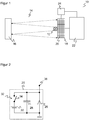
- FIG. 2 shows an exemplary simplified equivalent circuit of a single avalanche photodiode 20 in Geiger mode.
- the avalanche photodiode 20 shows, on the one hand, the behavior of a diode 26. It has a capacitance which is represented by a capacitor 28 connected in parallel.
- the possible avalanche breakdown generates charge carriers whose origin is represented in the equivalent circuit diagram as current source 30.
- the avalanche breakdown is triggered by an incident photon 32, which acts like a switch 34. There are then various ways to look at the output signal 36, which will not be discussed here.
- a bias voltage above the breakdown voltage is therefore a necessary prerequisite for an avalanche that can be triggered by individual photons 32. Nevertheless it acts not just a binary condition. The further the bias voltage is above the breakdown voltage, the greater the avalanche becomes, because more charge is available on the capacitor 28 before the voltage drops below the breakdown voltage and the avalanche thus disappears. The bias therefore affects the gain. However, changes in the bias voltage also affect the quantum efficiency of the avalanche photodiode 20, because the size of the drift zone forming also depends on the magnitude of the bias voltage. This means that the likelihood of avalanche release by a photon 32 increases with bias. Therefore, the bias of the avalanche photodiode 20 can be controlled. The effect just described is particularly evident, for example, in red-sensitive SPADs, reference being made for further details to the literature, for example the paper by Eisele cited in the opening paragraph.
- FIG. 3 illustrates a possible dynamic adaptation of the sensitivity during the measurement.
- the received light signal of an optoelectronic sensor 10 is often strongly dependent on the distance of the detected object 16, because the transmitted light is not or at least not perfectly collimated and usually only a small portion of the object 16 is reflected by diffuse remission. As a rule, therefore, a lot of signal is received in the near range, while in the far range the signal decreases. The maximum range for a given remission is determined by the smallest signal still detectable.
- the bias voltage may be used to adjust the sensitivity of the avalanche photodiodes 20 to a distance of an object 16.
- FIG. 3 a time course of the emitted light power in a pulse-based light transit time method shown. Concretely shown are two pulses of successive measurements.
- U B denotes a base voltage at or just above the breakdown voltage and dU the variable adjustment of the bias voltage.
- a low sensitivity is applied directly after the emission of a light pulse, which then increases before this ramp repeats for the subsequent measurement.
- the respective amplitude of the ramp, ie dU should preferably be such that sufficient signal is received in the near range and at maximum range the highest possible sensitivity is achieved.
- the time information of the X-axis can also be interpreted as a distance, since both can be converted into one another via the speed of light, whereby, however, a factor of two for the outward and return path of the light must be taken into account.
- the ramp thus shows the sensitivity with which an object 18 would be measured when it is at the appropriate distance. It is also conceivable to choose a more complicated function instead of a linear course of the ramp.
- the adjustment is according to FIG. 3 very fast.
- a long carrier lifetime in the semiconductor of the avalanche photodiode 20 could limit such highly dynamic adjustments, ie an avalanche photodiode 20 may still trigger erroneously due to an earlier received photon which had generated a not yet recombined charge carrier pair. It depends on the specific application whether such a disturbance event can be compensated for example by statistical evaluation of many avalanche photodiodes 20. In principle, the sensor 10 must be able to deal with similar events due to dark noise or ambient light anyway.
- the sensitivity is too high if the received signal overdrives, ie in particular trigger too many avalanche photodiodes 20.
- FIG. 4 shows a laser scanner as another embodiment of an optoelectronic sensor 10.
- Light emitter 12 and light receiver 18 is associated with an optical 38, 40, such optics usually also in a one-dimensional sensor 10 according to FIG. 1 are provided.
- the scanning beam of the light emitter 12 is coupled in via a first deflection unit 42 and directed via a second deflection unit 44 into the monitoring area 14.
- the second deflecting unit 44 designed as a mirror, for example, is rotatably mounted so that the scanning beam is periodically guided over a scanning plane.
- the rotatable second deflection unit 44 is provided with an encoder, so that the angular position is always known.
- the first deflection unit 42 covers only a negligible proportion of the reflected scanning beam, which thus almost completely strikes the light receiver 18 after renewed deflection at the second deflection unit 44 and is evaluated in the control and evaluation unit 22 in order to determine the distance of the object 16.
- the laser scanner gains distance profiles in its scan plane on the basis of the angular position and the distances.
- Numerous different structures of laser scanners are known, for example with a rotatable mirror polygon wheel or a total rotating measuring head with light emitter 12 and / or light receiver 18, which are also included in the invention.
- the bias of the light receiver 18 can be varied and thus its sensitivity can be adjusted.
- the highly dynamic adaptation within the individual pulse transit time measurements is conceivable, based on the FIG. 3 was explained.
- a slow dynamic adjustment can be made, which sets the sensitivity for each measurement. Since the environment does not change abruptly, the measurement information of at least the previous scan angle can be used for this purpose. The assumption is that the same object 16 is re-keyed at the next angle. If the assumption is not correct in some angular positions, for example at object edges, then the result is merely an unmatched individual measurement. Due to the slow adaptation of the sensitivity, the currents in the avalanche photodiodes 20 can be limited in the case of strongly reflecting objects 16 or even in strong ambient light.
Abstract
Es wird ein optoelektronischer Sensor (10) zur Erfassung eines Objekts (16) in einem Überwachungsbereich (14) mit einem Lichtempfänger (18), der eine Vielzahl von Lawinenphotodiodenelementen (20) zur Erfassung von Empfangslicht aus dem Überwachungsbereich (14) aufweist, die jeweils mit einer Vorspannung oberhalb einer Durchbruchspannung vorgespannt und somit in einem Geiger-Modus betrieben sind, und mit einer Steuer- und Auswerteeinheit (22) zur Auswertung eines Empfangssignals des Lichtempfängers (18) angegeben. Dabei ist eine Empfindlichkeits-Einstelleinheit (24) vorgesehen, mittels derer die Empfindlichkeit des Lichtempfängers (18, 20) durch Einstellen der Vorspannung veränderbar ist, wobei die Steuer- und Auswerteeinheit (22) dafür ausgebildet ist, die Empfindlichkeit anhand eines erwarteten Abstands des Objekts (16) dynamisch anzupassen.

Description
Die Erfindung betrifft einen optoelektronischen Sensor und ein Verfahren zur Erfassung eines Objekts in einem Überwachungsbereich nach dem Oberbegriff von Anspruch 1 beziehungsweise 11.The invention relates to an optoelectronic sensor and a method for detecting an object in a surveillance area according to the preamble of claim 1 or 11.
Optoelektronische Sensoren gibt es in einem breiten Spektrum, das von eindimensionalen Lichtschranken und Lichttastern über Laserscanner bis zu Kameras reicht. Über die reine Objekterfassung hinaus wird in entfernungsmessenden Systemen auch eine Distanz zu dem Objekt bestimmt. Distanzsensoren nach dem Lichtlaufzeitprinzip messen dazu die Laufzeit eines Lichtsignals, die über die Lichtgeschwindigkeit der Entfernung entspricht. Man unterscheidet herkömmlich die pulsbasierte und die phasenbasierte Messung. In einem Pulslaufzeitverfahren wird ein kurzer Lichtpuls ausgesandt und die Zeit bis zum Empfang einer Remission oder Reflexion des Lichtpulses gemessen. Alternativ wird bei einem Phasenverfahren Sendelicht amplitudenmoduliert und eine Phasenverschiebung zwischen Sende- und Empfangslicht bestimmt, wobei die Phasenverschiebung ebenfalls ein Maß für die Lichtlaufzeit ist. Die Grenze zwischen den beiden Verfahren lässt sich aber nicht immer scharf ziehen, denn etwa bei komplexen Pulsmustern wird ein Pulslaufzeitverfahren einem Phasenverfahren ähnlicher als einer klassischen Einzelpulsmessung.Optoelectronic sensors are available in a broad spectrum, ranging from one-dimensional photoelectric sensors and light sensors to laser scanners and cameras. In addition to pure object detection, a distance to the object is also determined in distance-measuring systems. Distance sensors based on the time-of-flight principle measure the propagation time of a light signal that corresponds to the distance over the speed of light. Conventionally, a distinction is made between pulse-based and phase-based measurements. In a pulse transit time method, a short light pulse is emitted and the time to receive a remission or reflection of the light pulse is measured. Alternatively, in a phase method, transmitted light is amplitude modulated and a phase shift between transmitted and received light is determined, wherein the phase shift is also a measure of the light transit time. However, the boundary between the two methods can not always be drawn sharply, because, for example, in the case of complex pulse patterns, a pulse transit time method is more similar to a phase method than to a classical single pulse measurement.
Um den Messbereich zu erweitern, kann der Abtaststrahl bewegt werden, wie dies in einem Laserscanner geschieht. Dort überstreicht ein von einem Laser erzeugter Lichtstrahl mit Hilfe einer Ablenkeinheit periodisch den Überwachungsbereich. Zusätzlich zu der gemessenen Abstandinformation wird aus der Winkelstellung der Ablenkeinheit auf die Winkellage des Objektes geschlossen, und damit ist der Ort eines Objektes in dem Überwachungsbereich in zweidimensionalen Polarkoordinaten erfasst. In den meisten Laserscannern wird die Abtastbewegung durch einen Drehspiegel erreicht. Es ist aber auch bekannt, stattdessen den gesamten Messkopf mit Lichtsendern und Lichtempfängern rotieren zu lassen, wie dies beispielsweise in
Um auch geringe Empfangsintensitäten nachweisen zu können, werden herkömmlich in manchen optoelektronischen Sensoren Lawinenphotodioden eingesetzt (APD, Avalanche Photo Diode). Das einfallende Licht löst hier einen kontrollierten Lawinendurchbruch (Avalanche Effect) aus. Dadurch werden die durch einfallende Photonen erzeugten Ladungsträger vervielfacht, und es entsteht ein Photostrom, der zu der Lichtempfangsintensität proportional, dabei aber wesentlich größer ist als bei einer einfachen PIN-Diode.In order to be able to detect even low reception intensities, avalanche photodiodes are conventionally used in some optoelectronic sensors (APD, avalanche photo diode). The incident light triggers a controlled avalanche breakdown. As a result, the charge carriers generated by incident photons are multiplied, and there is a photocurrent, which is proportional to the light receiving intensity, but much larger than a simple PIN diode.
Eine noch größere Empfindlichkeit wird mit Lawinenphotodioden erreicht, die im sogenannten Geiger-Modus betrieben werden (SPAD, Single Photon Avalanche Diode). Hierbei wird die Lawinenphotodiode oberhalb der Durchbruchspannung vorgespannt, so dass bereits ein einziger, durch ein einzelnes Photon freigesetzter Ladungsträger eine nicht mehr kontrollierte Lawine auslösen kann, die dann aufgrund der hohen Feldstärke sämtliche verfügbaren Ladungsträger rekrutiert. Danach kommt die Lawine zum Erliegen (passive quenching) und steht für eine gewisse Totzeit nicht mehr zur Detektion zur Verfügung. Alternativ ist auch bekannt, die Lawine von außen zu erkennen und zu löschen (active quenching). Bezüglich dieser und weiterer allgemeiner Eigenschaften von SPADs sei beispielhaft auf den Artikel
Eine SPAD zählt somit wie ein Geigerzähler Einzelereignisse. SPADs sind nicht nur hochempfindlich, sondern auch vergleichsweise kostengünstig. Zudem lassen sie sich mit wenig Aufwand auf einer Leiterkarte integrieren. Eine Besonderheit ist die Tatsache, dass auch ein minimales Störereignis, wie ein Fremdlichtphoton oder Dunkelrauschen, das gleiche maximale Empfangssignal erzeugt wie ein Nutzlichtsignal. Um diese Auswirkungen zu begrenzen, werden in der Praxis mehrere SPADs gemeinsam ausgewertet. Nach einem starken Empfangssignal befinden sich aber dennoch zumindest nahezu alle Zellen in ihrer Erholungsphase, und die Sensitivität des Lichtempfängers kehrt erst langsam zurück. Die Empfindlichkeit des Systems hat also ein Gedächtnis auf der Zeitskala der Totzeit. Außerdem werden durch die extrem hohe Verstärkung hohe Empfangsströme mit einer erheblichen Verlustleistung und damit Wärmeentwicklung erzeugt.A SPAD thus counts as a Geiger counter individual events. SPADs are not only highly sensitive but also relatively inexpensive. In addition, they can be integrated with little effort on a printed circuit board. A special feature is the fact that even a minimal disturbance event, such as an extraneous light photon or dark noise, generates the same maximum received signal as a useful light signal. To limit these effects, several SPADs are evaluated together in practice. After a strong received signal, however, at least almost all cells are still in their recovery phase, and the sensitivity of the light receiver returns only slowly. The sensitivity of the system thus has a memory on the time scale of the dead time. Moreover, due to the extremely high gain generates high receiving currents with a considerable power loss and thus heat generation.
Die
In der
Es ist daher Aufgabe der Erfindung, einen optoelektronischen Sensor mit Lawinenphotodioden im Geigermodus beziehungsweise SPADs mit verbesserten Messeigenschaften anzugeben.It is therefore an object of the invention to provide an optoelectronic sensor with avalanche photodiodes in Geiger mode or SPADs with improved measurement properties.
Diese Aufgabe wird durch einen optoelektronischen Sensor und ein Verfahren zur Erfassung eines Objekts in einem Überwachungsbereich nach Anspruch 1 beziehungsweise 11 gelöst. Die Erfindung geht von dem Grundgedanken aus, dass durch Anpassung der Vorspannung nicht nur die Verstärkung, sondern auch der Quantenwirkungsgrad und damit die Empfindlichkeit eines SPAD-Empfängers einstellbar ist. Denn je höher die Vorspannung ist, umso wahrscheinlicher wird es, dass ein einfallendes Photon auch tatsächlich eine Lawine auslöst. Die Steuer- und Auswerteeinheit passt dynamisch über die Vorspannung die Empfindlichkeit entsprechend dem Abstand des erfassten oder zu erfassenden Objekts an. Die notwendigen Informationen über den Objektabstand können je nach Ausführungsform auf vielfältige Weise zur Verfügung stehen, sei es durch Messung, Vorgabe, Annahme oder indem nacheinander die Empfindlichkeit für verschiedene Abstände eingestellt wird. Eine Beziehung zwischen einer jeweils einzustellenden Empfindlichkeit und der dafür erforderlichen Vorspannung kann vorbekannt oder eingelernt und beispielsweise als Tabelle (LUT, Lookup Table) hinterlegt sein. Alternativ wird die Empfindlichkeit anhand eines Signal-zu-Rausch-Verhältnisses eines Empfangssignals des SPAD-Empfängers eingestellt. Das entspricht hier dem Verhältnis von wieder empfangenem Sendelicht, dem gewünschten Signal, zu dem Umgebungslicht, da letzteres maßgeblichen Anteil am Rauschen hat. In Situationen mit einem großen Signal-zu-Rausch-Verhältnis ist eine geringe Empfindlichkeit des SPAD-Empfängers für eine erfolgreiche Detektion ausreichend. Ist das Signal-zu-Rausch-Verhältnis hingegen gering, ist eine hohe Empfindlichkeit vorteilhaft, um keine Information zu verlieren.This object is achieved by an optoelectronic sensor and a method for detecting an object in a surveillance area according to claim 1 or 11. The invention is based on the basic idea that by adjusting the bias not only the gain, but also the quantum efficiency and thus the sensitivity of a SPAD receiver is adjustable. The higher the bias, the more likely it will be that an incident photon actually triggers an avalanche. The control and evaluation unit dynamically adjusts the sensitivity according to the distance of the detected or to be detected object via the bias voltage. Depending on the embodiment, the necessary information about the object distance can be available in a variety of ways, be it by measurement, specification, acceptance or by successively setting the sensitivity for different distances. A relationship between each set sensitivity and the required bias voltage may be known or taught and deposited, for example as a table (LUT, Lookup Table) be. Alternatively, the sensitivity is adjusted based on a signal-to-noise ratio of a received signal of the SPAD receiver. This corresponds to the ratio of received back light, the desired signal, to the ambient light, since the latter has a significant share of the noise. In situations with a large signal-to-noise ratio, low sensitivity of the SPAD receiver is sufficient for successful detection. By contrast, if the signal-to-noise ratio is low, high sensitivity is advantageous in order to avoid losing information.
Die Erfindung hat den Vorteil, dass der Sensor besonders gut an die tatsächlichen Lichtsignale angepasst ist. Da die Vorspannung sehr schnell verändert werden kann, ist die Anpassung hoch dynamisch möglich. Zudem ist die Vorspannung gut zugänglich und damit eine einfache Umsetzung der Erfindung möglich. Insbesondere wird durch die angepasste Empfindlichkeit oder Sensitivität eine Übersteuerung für nahe Objekte und eine mangelnde Empfindlichkeit für ferne Objekte sehr einfach und wirkungsvoll vermieden.The invention has the advantage that the sensor is particularly well adapted to the actual light signals. Since the bias voltage can be changed very quickly, the adaptation is highly dynamic possible. In addition, the bias is easily accessible and thus a simple implementation of the invention possible. In particular, the adjusted sensitivity or sensitivity very easily and effectively avoids over-driving for nearby objects and lack of sensitivity for distant objects.
Der Sensor ist vorzugsweise ein entfernungsmessender Sensor mit einem Lichtsender zum Aussenden eines Lichtsignals, wobei die Steuer- und Auswertungseinheit dafür ausgebildet ist, aus einer Lichtlaufzeit zwischen Aussenden des Lichtsignals und Empfangen des von dem Objekt aus dem Überwachungsbereich remittierten Lichtsignals einen Abstand des Objekts zu bestimmen. Bei einem solchen Sensor ist der erwartete Abstand, an den die Empfindlichkeit erfindungsgemäß angepasst wird, ganz besonders relevant, weil der tatsächliche Abstand die Messgröße eines solchen Sensors ist. Daher bewirkt diese Anpassung auch eine besonders deutliche Verbesserung.The sensor is preferably a distance-measuring sensor with a light transmitter for emitting a light signal, wherein the control and evaluation unit is adapted to determine a distance of the object from a light transit time between emission of the light signal and receiving the remitted from the object from the monitoring area light signal. In such a sensor, the expected distance to which the sensitivity is adjusted according to the invention is very particularly relevant because the actual distance is the measurement of such a sensor. Therefore, this adjustment also causes a particularly significant improvement.
Das Lichtsignal weist bevorzugt einen Lichtpuls auf. Der Sensor misst also Entfernungen nach dem Pulsverfahren. Dabei sind auch kompliziertere Formen wie Doppelpulse oder sogar Pulscodes denkbar. Es können auch mehrere Lichtpulse nacheinander ausgesandt, empfangen und die jeweiligen Einzelergebnisse gemeinsam statistisch ausgewertet werden, etwa in einem Pulsmittelungsverfahren. Alternativ ist ein Phasenverfahren denkbar, denn auch hier hängt die Empfangsintensität von der Objektentfernung ab.The light signal preferably has a light pulse. The sensor thus measures distances according to the pulse method. Even more complicated forms such as double pulses or even pulse codes are conceivable. It is also possible for a plurality of light pulses to be transmitted one after the other, received, and the respective individual results jointly evaluated statistically, for example in a pulse averaging process. Alternatively, a phase method is conceivable, since the reception intensity also depends on the object distance.
Die Steuer- und Auswerteeinheit ist bevorzugt dafür ausgebildet, die Empfindlichkeit von einer geringen Empfindlichkeit im Nahbereich zu einer hohen Empfindlichkeit im Fernbereich zu variieren. Die Empfindlichkeit ist besonders bevorzugt gerade so austariert, dass ein Objekt direkt vor dem Sensor den Lichtempfänger nicht übersteuert, was im Zusammenhang mit einem SPAD-Detektor bedeutet, zumindest einen Großteil der Zellen in die Totzeit zu versetzen, und in hoher Reichweite eine maximale Empfindlichkeit erreicht wird. Dazwischen sollte die Empfangsleistung monoton ansteigen. Diese abstandsabhängige Sollempfindlichkeit kann pro Geräteklasse oder sogar individuell je Einzelgerät eingelernt werden. Alternativ wird beispielsweise einfach mit einer minimalen Vorspannung knapp oberhalb der Durchbruchsspannung im Nahbereich, einer deutlich erhöhten Vorspannung im Fernbereich und interpolierten Zwischenwerten gearbeitet.The control and evaluation unit is preferably designed to reduce the sensitivity from a low sensitivity in the near range to a high sensitivity in the Far range to vary. The sensitivity is particularly preferably just balanced such that an object directly in front of the sensor does not override the light receiver, which in connection with a SPAD detector means putting at least a large part of the cells into dead time and achieving maximum sensitivity over a long range becomes. In between, the reception power should increase monotonously. This distance-dependent target sensitivity can be taught in per device class or even individually for each individual device. Alternatively, for example, simply work with a minimum bias just above the breakdown voltage in the near range, a significantly increased bias in the far range and interpolated intermediate values.
Die Steuer- und Auswertungseinheit ist bevorzugt dafür ausgebildet, die Empfindlichkeit kontinuierlich oder in Stufen von geringer Empfindlichkeit zu hoher Empfindlichkeit zu variieren. Die Variation der Empfindlichkeit erfolgt also in einer Art Rampe. Das ist vor allem dann sinnvoll, wenn über die tatsächliche Objektentfernung nichts bekannt ist. Die Rampe kann sich zyklisch wiederholen, sei es innerhalb einer Messung oder über eine oder mehrere Messungen. Eine kontinuierliche Rampe ermöglicht eine genauere Anpassung, während eine gestufte Rampe der SPAD etwas Zeit gibt, sich auf die neue Empfindlichkeit einzustellen.The control and evaluation unit is preferably designed to vary the sensitivity continuously or in stages from low sensitivity to high sensitivity. The variation of the sensitivity thus takes place in a kind of ramp. This is especially useful if nothing is known about the actual object distance. The ramp can be repeated cyclically, be it within a measurement or over one or more measurements. A continuous ramp allows a more accurate adjustment, while a stepped ramp gives the SPAD some time to adjust to the new sensitivity.
Die Steuer- und Auswertungseinheit ist bevorzugt dafür ausgebildet, die Empfindlichkeit zunächst gering einzustellen und dann entsprechend der Ausbreitungsgeschwindigkeit von Licht im Überwachungsbereich zu erhöhen. Das ist besonders geeignet für ein pulsbasiertes Lichtlaufzeitverfahren. Die Empfindlichkeit passt dann für alle potentiellen Empfangszeiten zu der Entfernung eines Objekts, das in diesem Moment erfasst würde. Praktisch kann dafür zunächst theoretisch oder durch Messung eine Beziehung bestimmt werden, wie stark die Empfangsintensität mit der Entfernung abnimmt. Diese ortsabhängige Beziehung ist über die Lichtgeschwindigkeit direkt in eine zeitabhängige Beziehung umrechenbar. Dabei sollte aber darauf geachtet werden, dass effektiv nur die halbe Lichtgeschwindigkeit zum Tragen kommt, weil auch der Rückweg eines am Objekt remittierten Lichtsignals berücksichtigt werden muss. Die relevante Ausbreitungsgeschwindigkeit ist typischerweise die Vakuumlichtgeschwindigkeit, aber eine langsamere Lichtgeschwindigkeit in anderen Medien prinzipiell denkbar.The control and evaluation unit is preferably designed to initially set the sensitivity to low and then to increase it in accordance with the propagation speed of light in the monitoring area. This is particularly suitable for a pulse-based light transit time method. The sensitivity then matches the distance of an object that would be detected at that moment for all potential reception times. In practice, a relationship can first be determined theoretically or by measurement to determine how much the reception intensity decreases with distance. This location-dependent relationship can be converted directly into a time-dependent relationship via the speed of light. However, care should be taken that effectively only half the speed of light comes to fruition, because the return path of a remitted to the object light signal must be considered. The relevant propagation velocity is typically the vacuum light velocity, but a slower speed of light in other media is in principle conceivable.
Die Steuer- und Auswertungseinheit ist bevorzugt dafür ausgebildet, die Empfindlichkeit innerhalb einer Messung anzupassen. Die soeben erläuterte Ausführungsform mit dynamischer Anpassung der Empfindlichkeit an die Zeit seit Aussenden eines Lichtpulses ist dafür ein Beispiel. Solche Anpassungen sind also sehr schnell.The control and evaluation unit is preferably designed to adjust the sensitivity within a measurement. The just explained embodiment with Dynamic adaptation of the sensitivity to the time since the emission of a light pulse is an example. Such adjustments are very fast.
Die Steuer- und Auswertungseinheit ist bevorzugt dafür ausgebildet, die Empfindlichkeit zwischen zwei Messungen anzupassen. Das ist eine langsamere dynamische Anpassung, die auch auf eine Trägheit der SPADs, wie etwa durch Halbwertszeiten von Ladungsträgerpaaren Rücksicht nimmt. Die Anpassung erfolgt dabei vorzugsweise bei einem entfernungsmessenden Sensor anhand des letzten Messergebnisses. Schnelle und langsame Anpassungen schließen einander nicht zwingend aus, sondern können unter Umständen auch kombiniert werden, beispielsweise indem der schnellen Anpassung durch die langsame Anpassung ein Rahmen oder ein Offset vorgegeben wird.The control and evaluation unit is preferably designed to adjust the sensitivity between two measurements. This is a slower dynamic fit, which also takes into account inertia of the SPADs, such as half-lives of carrier pairs. The adjustment is preferably carried out at a distance-measuring sensor based on the last measurement result. Fast and slow adjustments are not necessarily mutually exclusive, but can sometimes be combined, for example by setting a frame or an offset for the fast adaptation by means of the slow adaptation.
Der Sensor ist bevorzugt als Laserscanner mit einem Lichtsender und einer beweglichen Ablenkeinheit zur periodischen Ablenkung des Lichtstrahls in dem Überwachungsbereich ausgebildet. Als Scanmechanismus kommen alle bekannten Konzepte wie Schwing- und Drehspiegel oder beweglicher Messkopf in Betracht. Üblicherweise wird auch das Empfangslicht periodisch abgelenkt, wobei es aber auch Scanner gibt, die einen statischen Matrixchip benutzen und durch elektronische Ansteuerung je nach Messrichtung eine aktive Pixelgruppe nachführen. Ein Laserscanner ist vorzugsweise entfernungsmessend, hat also ein Lichtlaufzeitverfahren implementiert. Dabei ist dann die in den beiden vorigen Absätzen erläuterte schnelle und/oder langsame Dynamik denkbar. Die schnelle Dynamik macht keine Annahmen über die zu messenden Abstände. Die langsame Dynamik nimmt an, dass zwei direkt aufeinanderfolgende Abtastungen in aller Regel dasselbe Objekt treffen. An einer Kante trifft das nicht zu, aber die noch fälschlich auf die Kante eingestellte Empfindlichkeit funktioniert zumindest auch nicht schlechter als eine herkömmliche konstante Empfindlichkeit.The sensor is preferably designed as a laser scanner with a light transmitter and a movable deflection unit for the periodic deflection of the light beam in the monitoring area. The scanning mechanism all known concepts such as oscillating and rotating mirror or movable measuring head into consideration. Usually, the receiving light is deflected periodically, but there are also scanners that use a static matrix chip and track by electronic control depending on the direction of measurement an active pixel group. A laser scanner is preferably distance-measuring, so it has implemented a light-time-time method. In this case, the fast and / or slow dynamics explained in the two preceding paragraphs are conceivable. The fast dynamics makes no assumptions about the distances to be measured. The slow dynamics assume that two consecutive samples usually hit the same object. This is not true at one edge, but the sensitivity that has been erroneously set to the edge is at least no worse than a conventional constant sensitivity.
Die Lawinenphotodiodenelemente sind bevorzugt rotempfindlich. Das ist ein Typ von SPADs, wie beispielsweise in der eingangs zitierten Arbeit Eisele et al. beschrieben, welche deutlich die Eigenschaft zeigen, dass mit der Vorspannung auch der Quantenwirkungsgrad, damit die Auslösungswahrscheinlichkeit und letztlich die Empfindlichkeit variiert. Damit eignen sich diese SPADs besonders für das erfindungsgemäße Vorgehen.The avalanche photodiode elements are preferably red sensitive. This is a type of SPADs, as for example in the work quoted above Eisele et al. described, which clearly show the property that with the bias voltage and the quantum efficiency, so that the probability of triggering and ultimately the sensitivity varies. Thus, these SPADs are particularly suitable for the procedure according to the invention.
Das erfindungsgemäße Verfahren kann auf ähnliche Weise weitergebildet werden und zeigt dabei ähnliche Vorteile. Derartige vorteilhafte Merkmale sind beispielhaft, aber nicht abschließend in den sich an die unabhängigen Ansprüche anschließenden Unteransprüchen beschrieben.The method according to the invention can be developed in a similar manner and shows similar advantages. Such advantageous features are exemplary, but not described exhaustively in the dependent claims subsequent to the independent claims.
Die Erfindung wird nachstehend auch hinsichtlich weiterer Merkmale und Vorteile beispielhaft anhand von Ausführungsformen und unter Bezug auf die beigefügte Zeichnung näher erläutert. Die Abbildungen der Zeichnung zeigen in:
- Fig. 1
- eine schematische Blockdarstellung eines optoelektronischen Sensors;
- Fig. 2
- ein vereinfachtes Blockschaltbild einer Lawinendiode im Geigermodus oder SPAD;
- Fig. 3
- ein beispielhafter zeitlicher Verlauf der Lichtleistung (oben) und der entfernungsabhängig angepassten Vorspannung und damit Empfindlichkeit des Lichtempfängers (unten); und
- Fig.4
- eine schematische Blockdarstellung einer Ausführungsform des optoelektronischen Sensors als Laserscanner.
- Fig. 1
- a schematic block diagram of an optoelectronic sensor;
- Fig. 2
- a simplified block diagram of an avalanche diode in Geiger mode or SPAD;
- Fig. 3
- an exemplary time profile of the light output (above) and the distance-dependent adjusted bias voltage and thus sensitivity of the light receiver (bottom); and
- Figure 4
- a schematic block diagram of an embodiment of the optoelectronic sensor as a laser scanner.
In
Die Auftrennung in Lichtempfänger 18, Steuer- und Auswertungseinheit 22 und Einstelleinheit 24 in
Der Sensor 10 ist bevorzugt entfernungsmessend. Dazu bestimmt die Steuer- und Auswertungseinheit 22 eine Lichtlaufzeit von Aussenden eines Lichtsignals bis zu dessen Empfang und rechnet dies über die Lichtgeschwindigkeit in einen Abstand um. Mehrere Sensoren 10 können kombiniert werden, um ein tastendes Lichtgitter mit mehreren, meist parallelen Strahlen zu bilden, welches in jedem Strahl Entfernungen misst oder überwacht. Auch mobile Systeme sind denkbar, bei denen der Sensor 10 beweglich montiert ist.The
Im Bereitschaftszustand liegt über der Diode 26 eine Spannung oberhalb der Durchbruchspannung an. Erzeugt dann ein einfallendes Photon 32 ein Ladungsträgerpaar, so schließt dies gleichsam den Schalter 34, so dass die Lawinenphotodiode 20 über die Stromquelle 30 mit Ladungsträgern geflutet wird. Neue Ladungsträger entstehen aber nur, solange das elektrische Feld stark genug bleibt. Wird durch die Stromquelle 30 der Kondensator 28 so weit entladen, dass die Durchbruchspannung unterschritten ist, so kommt die Lawine von selbst zum Erliegen ("passive quenching"). Danach lädt sich der Kondensator 28 wieder auf, bis wieder eine Spannung über der Durchbruchspannung an der Diode 26 anliegt. Es gibt alternative Ausgestaltungen, in denen die Lawine von außen erkannt und daraufhin eine Entladung unter die Durchbruchspannung ausgelöst wird ("active quenching").In the standby state, a voltage above the
Eine Vorspannung oberhalb der Durchbruchspannung ist demnach notwendige Voraussetzung einer durch einzelne Photonen 32 auslösbare Lawine. Dennoch handelt es sich nicht einfach um eine binäre Bedingung. Je weiter die Vorspannung oberhalb der Durchbruchspannung liegt, umso stärker wird die Lawine, weil auf dem Kondensator 28 mehr Ladung verfügbar ist, ehe die Spannung unter die Durchbruchspannung fällt und die Lawine damit erlischt. Die Vorspannung beeinflusst demnach die Verstärkung. Änderungen der Vorspannung wirken sich aber auch auf den Quantenwirkungsgrad der Lawinenphotodiode 20 aus, weil die Größe der sich ausbildenden Driftzone ebenfalls von der Höhe der Vorspannung abhängt. Das bedeutet, dass die Wahrscheinlichkeit einer Lawinenauslösung durch ein Photon 32 mit der Vorspannung steigt. Deshalb kann über die Vorspannung die Empfindlichkeit der Lawinenphotodiode 20 gesteuert werden. Der soeben beschriebene Effekt zeigt sich besonders deutlich beispielsweise bei rotempfindlichen SPADs, wobei für weitere Einzelheiten auf die Literatur, etwa die einleitend genannte Arbeit von Eisele verwiesen wird.A bias voltage above the breakdown voltage is therefore a necessary prerequisite for an avalanche that can be triggered by
Um ein Beispiel zu geben, ist im oberen Teil der
Dem unteren Verlauf der Vorspannung folgend wird demnach in dieser Ausführungsform direkt nach dem Aussenden eines Lichtpulses mit einer niedrigen Empfindlichkeit gearbeitet, die dann ansteigt, ehe sich diese Rampe für die Folgemessung wiederholt. Die jeweilige Amplitude der Rampe, d.h. dU, sollte vorzugsweise so bemessen sein, dass im Nahbereich ausreichend Signal empfangen wird und bei maximaler Reichweite eine möglichst hohe Empfindlichkeit erreicht ist. Die Zeitinformation der X-Achse lässt sich auch als Abstand auffassen, da beides über die Lichtgeschwindigkeit ineinander umrechenbar ist, wobei allerdings ein Faktor zwei für Hin- und Rückweg des Lichts berücksichtigt werden muss. Die Rampe zeigt demnach die Empfindlichkeit, mit der ein Objekt 18 gemessen würde, wenn es sich im entsprechenden Abstand befindet. Es ist auch denkbar, anstelle eines linearen Verlaufs der Rampe eine kompliziertere Funktion zu wählen.Accordingly, in this embodiment, following the lower course of the bias, a low sensitivity is applied directly after the emission of a light pulse, which then increases before this ramp repeats for the subsequent measurement. The respective amplitude of the ramp, ie dU, should preferably be such that sufficient signal is received in the near range and at maximum range the highest possible sensitivity is achieved. The time information of the X-axis can also be interpreted as a distance, since both can be converted into one another via the speed of light, whereby, however, a factor of two for the outward and return path of the light must be taken into account. The ramp thus shows the sensitivity with which an
Bedingt durch die Lichtgeschwindigkeit ist die Anpassung gemäß
In manchen Anwendungen kann es dennoch vorteilhaft sein, die Empfindlichkeit auf einer langsameren Zeitskala anzupassen. Dabei wird beispielsweise Vorwissen aus früheren Messungen genutzt, um die Empfindlichkeit auf den tatsächlichen Abstand des Objekts 18 einzustellen und die Messung dadurch zu verfeinern.Nevertheless, in some applications it may be advantageous to adjust the sensitivity on a slower time scale. In this case, for example, prior knowledge from previous measurements is used to set the sensitivity to the actual distance of the
Weiterhin ist denkbar, die Empfindlichkeit anhand eines Signal-zu-Rausch-Verhältnisses einzustellen. Vor allem der variable Anteil des Rauschens wird maßgeblich durch das Umgebungslicht verursacht. Andere Anteile wie ein Dunkelrauschen sind gleichmäßiger. Eine Bestimmung des Umgebungslichts, etwa durch Messung mit dem Lichtempfänger 18 ohne Aussenden von Lichtsignalen durch den Lichtsender 12 ermöglicht daher eine gute Schätzung des Signal-zu-Rausch-Verhältnisses. Eine andere Möglichkeit ist, das Empfangssignal selbst zu bewerten und ein zu hohes Signal-zu-Rausch-Verhältnis beispielsweise dann anzunehmen, wenn sich das Empfangssignal nicht von einem reinen Zufallssignal unterscheidet beziehungsweise darin keine Anteile des wieder empfangenen eigenen Lichtsignals des Lichtsenders 12 aufzufinden sind. Umgekehrt ist die Empfindlichkeit zu hoch, wenn das Empfangssignal übersteuert, also insbesondere zu viele Lawinenphotodioden 20 auslösen.Furthermore, it is conceivable to set the sensitivity based on a signal-to-noise ratio. Above all, the variable component of the noise is largely caused by the ambient light. Other components, such as dark noise, are more uniform. A determination of the ambient light, such as by measurement with the
Über die Einstelleinheit 24 kann die Vorspannung des Lichtempfängers 18 variiert und damit dessen Empfindlichkeit eingestellt werden. Dazu ist insbesondere die hochdynamische Anpassung innerhalb der einzelnen Pulslaufzeitmessungen denkbar, die anhand der
Claims (12)
eine Empfindlichkeits-Einstelleinheit (24), mittels derer die Empfindlichkeit des Lichtempfängers (18, 20) durch Einstellen der Vorspannung veränderbar ist, wobei die Steuer- und Auswerteeinheit (22) dafür ausgebildet ist, die Empfindlichkeit anhand eines erwarteten Abstands des Objekts (16) oder eines Signal-zu-Rausch-Verhältnisses eines Empfangssignals des Lichtempfängers (18, 20) dynamisch anzupassen.An optoelectronic sensor (10) for detecting an object (16) in a surveillance area (14) comprising a light receiver (18) having a plurality of avalanche photodiode elements (20) for detecting received light from the surveillance area (14), each biased biased above a breakdown voltage and thus operated in a Geiger mode, and with a control and evaluation unit (22) for evaluating a received signal of the light receiver (18), characterized by
a sensitivity setting unit (24), by means of which the sensitivity of the light receiver (18, 20) is variable by adjusting the bias voltage, the control and evaluation unit (22) being adapted to measure the sensitivity based on an expected distance of the object (16) or a signal-to-noise ratio of a received signal of the light receiver (18, 20) dynamically adapt.
der ein entfernungsmessender Sensor mit einem Lichtsender (12) zum Aussenden eines Lichtsignals ist, wobei die Steuer- und Auswertungseinheit (22) dafür ausgebildet ist, aus einer Lichtlaufzeit zwischen Aussenden des Lichtsignals und Empfangen des von dem Objekt (16) aus dem Überwachungsbereich (14) remittierten Lichtsignals einen Abstand des Objekts (16) zu bestimmen.Sensor (10) according to claim 1,
which is a distance-measuring sensor with a light transmitter (12) for emitting a light signal, wherein the control and evaluation unit (22) is adapted to a light transit time between emitting the light signal and receiving from the object (16) from the monitoring area (14 ) remitted light signal to determine a distance of the object (16).
wobei das Lichtsignal einen Lichtpuls aufweist.Sensor (10) according to claim 2,
wherein the light signal comprises a light pulse.
wobei die Steuer- und Auswerteeinheit (22) dafür ausgebildet ist, die Empfindlichkeit von einer geringen Empfindlichkeit im Nahbereich zu einer hohen Empfindlichkeit im Fernbereich zu variieren.Sensor (10) according to one of the preceding claims,
wherein the control and evaluation unit (22) is adapted to vary the sensitivity from a low sensitivity in the near range to a high sensitivity in the far range.
wobei die Steuer- und Auswertungseinheit (22) dafür ausgebildet ist, die Empfindlichkeit kontinuierlich oder in Stufen von geringer Empfindlichkeit zu hoher Empfindlichkeit zu variieren.Sensor (10) according to one of the preceding claims,
wherein the control and evaluation unit (22) is adapted to increase the sensitivity continuously or in stages of low sensitivity high sensitivity to vary.
wobei die Steuer- und Auswertungseinheit (22) dafür ausgebildet ist, die Empfindlichkeit zunächst gering einzustellen und dann entsprechend der Ausbreitungsgeschwindigkeit von Licht im Überwachungsbereich (14) zu erhöhen.Sensor (10) according to one of the preceding claims,
wherein the control and evaluation unit (22) is adapted to initially set low the sensitivity and then increase according to the propagation speed of light in the monitoring area (14).
wobei die Steuer- und Auswertungseinheit (22) dafür ausgebildet ist, die Empfindlichkeit innerhalb einer Messung anzupassen.Sensor (10) according to one of the preceding claims,
wherein the control and evaluation unit (22) is adapted to adjust the sensitivity within a measurement.
wobei die Steuer- und Auswertungseinheit (22) dafür ausgebildet ist, die Empfindlichkeit zwischen zwei Messungen anzupassen.Sensor (10) according to one of the preceding claims,
wherein the control and evaluation unit (22) is adapted to adjust the sensitivity between two measurements.
der als Laserscanner mit einem Lichtsender (12) und einer beweglichen Ablenkeinheit (44) zur periodischen Ablenkung des Lichtstrahls in dem Überwachungsbereich (14) ausgebildet ist.Sensor (10) according to one of the preceding claims,
which is designed as a laser scanner with a light transmitter (12) and a movable deflection unit (44) for the periodic deflection of the light beam in the monitoring area (14).
wobei die Lawinenphotodiodenelemente (20) rotempfindlich sind.Sensor (10) according to one of the preceding claims,
wherein the avalanche photodiode elements (20) are red sensitive.
dadurch gekennzeichnet,
dass die Empfindlichkeit des Lichtempfängers (18, 20) durch Einstellen der Vorspannung anhand eines erwarteten Abstands des Objekts (16) oder eines Signal-zu-Rausch-Verhältnisses eines Empfangssignals des Lichtempfängers (18, 20) dynamisch angepasst wird.A method of detecting an object (16) in a surveillance area (14), wherein a received signal from light is generated from the surveillance area (14) with a light receiver (18) comprising a plurality of avalanche photodiode elements (20) for detecting received light from the Monitoring range (14), each biased with a bias voltage above a breakdown voltage and thus operated in a Geiger mode, and the received signal is evaluated,
characterized,
that the sensitivity of the light receiver (18, 20) by adjusting the bias voltage based on an expected distance of the object (16) or a signal-to-noise ratio of a received signal of the light receiver (18, 20) is adjusted dynamically.
wobei die Entfernung des Objekts (16) in einem Lichtlaufzeitverfahren bestimmt wird, indem ein Lichtpuls ausgesandt und die Lichtlaufzeit bis zum Empfang des von dem Objekt (16) aus dem Überwachungsbereich (14) remittierten Lichtsignals gemessen wird, und wobei die Empfindlichkeit beim Aussenden des Lichtpulses gering eingestellt und dann entsprechend der Ausbreitungsgeschwindigkeit des Lichtpulses im Überwachungsbereich (14) erhöht wird.Method according to claim 11,
wherein the distance of the object (16) is determined in a light transit time method by emitting a light pulse and measuring the light transit time until receipt of the light signal reflected from the monitoring area (14) by the object (16) and the sensitivity upon emission of the light pulse set low and then increased according to the propagation speed of the light pulse in the monitoring area (14).
Applications Claiming Priority (1)
| Application Number | Priority Date | Filing Date | Title |
|---|---|---|---|
| DE102016113131.8A DE102016113131A1 (en) | 2016-07-15 | 2016-07-15 | An optoelectronic sensor and method for detecting an object in a surveillance area |
Publications (1)
| Publication Number | Publication Date |
|---|---|
| EP3270182A1 true EP3270182A1 (en) | 2018-01-17 |
Family
ID=59077938
Family Applications (1)
| Application Number | Title | Priority Date | Filing Date |
|---|---|---|---|
| EP17176578.7A Withdrawn EP3270182A1 (en) | 2016-07-15 | 2017-06-19 | Optoelectronic sensor and method for detecting objects in a surveillance area |
Country Status (2)
| Country | Link |
|---|---|
| EP (1) | EP3270182A1 (en) |
| DE (1) | DE102016113131A1 (en) |
Cited By (3)
| Publication number | Priority date | Publication date | Assignee | Title |
|---|---|---|---|---|
| EP3611535A1 (en) | 2018-08-17 | 2020-02-19 | Sick Ag | Detection of light with a plurality of avalanche photodiode elements |
| EP4283331A1 (en) | 2022-05-24 | 2023-11-29 | Sick Ag | Optical detection and distance measurement |
| EP4303625A1 (en) * | 2022-07-05 | 2024-01-10 | Veoneer Sweden AB | Lidar system and method to operate |
Families Citing this family (2)
| Publication number | Priority date | Publication date | Assignee | Title |
|---|---|---|---|---|
| DE102018133281A1 (en) | 2018-12-21 | 2020-06-25 | Sick Ag | Sensor and method for detecting an object |
| RU2756384C1 (en) * | 2020-11-26 | 2021-09-29 | Акционерное общество "Научно-исследовательский институт "Полюс" им. М.Ф. Стельмаха" | Method for threshold reception of optical signals |
Citations (2)
| Publication number | Priority date | Publication date | Assignee | Title |
|---|---|---|---|---|
| US20120075615A1 (en) * | 2009-06-22 | 2012-03-29 | Toyota Motor Europe Nv/Sa | Pulsed light optical rangefinder |
| US20140231630A1 (en) * | 2013-02-18 | 2014-08-21 | Stmicroelectronics (Research & Development) Limited | Method and apparatus for image sensor calibration |
Family Cites Families (8)
| Publication number | Priority date | Publication date | Assignee | Title |
|---|---|---|---|---|
| US3644740A (en) * | 1969-07-22 | 1972-02-22 | Hughes Aircraft Co | Control circuit for biasing a photodetector so as to maintain a selected false alarm rate |
| US4077718A (en) * | 1976-03-01 | 1978-03-07 | Raytheon Company | Receiver for optical radar |
| US4464048A (en) * | 1981-03-25 | 1984-08-07 | Barr & Stroud Limited | Laser rangefinders |
| DE19757849C5 (en) | 1997-12-24 | 2013-11-21 | Sick Ag | Scanner and device for the optical detection of obstacles, and their use |
| EP1860462A1 (en) | 2006-05-23 | 2007-11-28 | Leica Geosystems AG | Distance measuring method and distance meter for determining the spatial dimension of a target |
| DE102009029372A1 (en) | 2009-09-11 | 2011-03-24 | Robert Bosch Gmbh | Measuring device for measuring a distance between the measuring device and a target object by means of optical measuring radiation |
| US9304203B1 (en) * | 2013-03-13 | 2016-04-05 | Google Inc. | Methods, devices, and systems for improving dynamic range of signal receiver |
| CN106165399B (en) * | 2014-04-07 | 2019-08-20 | 三星电子株式会社 | The imaging sensor of high-resolution, high frame per second, low-power |
-
2016
- 2016-07-15 DE DE102016113131.8A patent/DE102016113131A1/en active Pending
-
2017
- 2017-06-19 EP EP17176578.7A patent/EP3270182A1/en not_active Withdrawn
Patent Citations (2)
| Publication number | Priority date | Publication date | Assignee | Title |
|---|---|---|---|---|
| US20120075615A1 (en) * | 2009-06-22 | 2012-03-29 | Toyota Motor Europe Nv/Sa | Pulsed light optical rangefinder |
| US20140231630A1 (en) * | 2013-02-18 | 2014-08-21 | Stmicroelectronics (Research & Development) Limited | Method and apparatus for image sensor calibration |
Non-Patent Citations (1)
| Title |
|---|
| ANDREAS EISELE ET AL: "185 MHz Count Rate, 139 dB Dynamic Range Single-Photon Avalanche Diode with Active Quenching Circuit in 130 nm CMOS Technology", DIALOG SEMICONDUCTOR (UK) LTD, vol. 46, 8 June 2011 (2011-06-08), Japan, pages 278 - 281, XP055431702 * |
Cited By (5)
| Publication number | Priority date | Publication date | Assignee | Title |
|---|---|---|---|---|
| EP3611535A1 (en) | 2018-08-17 | 2020-02-19 | Sick Ag | Detection of light with a plurality of avalanche photodiode elements |
| US11294037B2 (en) | 2018-08-17 | 2022-04-05 | Sick Ag | Detecting light using a plurality of avalanche photodiode elements |
| EP4283331A1 (en) | 2022-05-24 | 2023-11-29 | Sick Ag | Optical detection and distance measurement |
| EP4303625A1 (en) * | 2022-07-05 | 2024-01-10 | Veoneer Sweden AB | Lidar system and method to operate |
| WO2024008532A1 (en) * | 2022-07-05 | 2024-01-11 | Veoneer Sweden Ab | Lidar system and method to operate |
Also Published As
| Publication number | Publication date |
|---|---|
| DE102016113131A1 (en) | 2018-01-18 |
Similar Documents
| Publication | Publication Date | Title |
|---|---|---|
| DE102017101501B3 (en) | An optoelectronic sensor and method for determining the distance of an object in a surveillance area | |
| EP3279685B1 (en) | Optoelectronic sensor and method for detecting an object | |
| EP2910969B1 (en) | Optoelectronic sensor and method for recording objects in a monitoring area | |
| EP3270182A1 (en) | Optoelectronic sensor and method for detecting objects in a surveillance area | |
| EP0793115B1 (en) | Laser radar scanner with millimeter resolution | |
| EP3450915B1 (en) | Total station or theodolite with scan functionality and adjustable receiving areas of the receiver | |
| EP2708913A1 (en) | Opto-electronic sensor and object detection method | |
| DE202013105389U1 (en) | Optoelectronic sensor with avalanche photodiode elements operated in Geiger mode | |
| DE102018126522A1 (en) | Runtime-based distance measurement using modulated pulse trains of laser pulses | |
| EP3355078B1 (en) | Optoelectronic sensor and method for detecting objects | |
| EP3770633A1 (en) | Optoelectronic sensor and distance measurement method | |
| EP3839556B1 (en) | Optoelectronic sensor and method for detecting an object | |
| EP3454086A1 (en) | Optoelectronic sensor and method for detecting the position of an object | |
| EP3671276B1 (en) | Optoelectronic sensor and method for detecting an object | |
| EP3650888B1 (en) | Optoelectronic sensor and method for recording and determining the distance of an object | |
| WO2018172258A1 (en) | Spad-based lidar system | |
| DE202016104285U1 (en) | Optoelectronic sensor for detecting an object | |
| EP4249950B1 (en) | Detection of an object and distance measurement | |
| EP4249949B1 (en) | Detection of an object and distance measurement | |
| DE102020106359B4 (en) | Distance determination of objects | |
| DE202017103345U1 (en) | Tasting light grid for detecting objects | |
| EP2910972B1 (en) | Distance measuring sensor and method for determing the distance from objects in a monitoring zone | |
| EP3663798B1 (en) | Optoelectronic sensor and method for recording and determining the distance of an object | |
| DE102010064682B3 (en) | Optoelectronic sensor and method for detecting and determining the distance of objects | |
| EP4283331A1 (en) | Optical detection and distance measurement |
Legal Events
| Date | Code | Title | Description |
|---|---|---|---|
| PUAI | Public reference made under article 153(3) epc to a published international application that has entered the european phase |
Free format text: ORIGINAL CODE: 0009012 |
|
| AK | Designated contracting states |
Kind code of ref document: A1 Designated state(s): AL AT BE BG CH CY CZ DE DK EE ES FI FR GB GR HR HU IE IS IT LI LT LU LV MC MK MT NL NO PL PT RO RS SE SI SK SM TR |
|
| AX | Request for extension of the european patent |
Extension state: BA ME |
|
| 17P | Request for examination filed |
Effective date: 20180517 |
|
| RBV | Designated contracting states (corrected) |
Designated state(s): AL AT BE BG CH CY CZ DE DK EE ES FI FR GB GR HR HU IE IS IT LI LT LU LV MC MK MT NL NO PL PT RO RS SE SI SK SM TR |
|
| 17Q | First examination report despatched |
Effective date: 20180706 |
|
| STAA | Information on the status of an ep patent application or granted ep patent |
Free format text: STATUS: THE APPLICATION HAS BEEN WITHDRAWN |
|
| 18W | Application withdrawn |
Effective date: 20180827 |