EP3270043A1 - Mehrkomponentenreflektor für lichtmodul eines kraftfahrzeugscheinwerfers - Google Patents
Mehrkomponentenreflektor für lichtmodul eines kraftfahrzeugscheinwerfers Download PDFInfo
- Publication number
- EP3270043A1 EP3270043A1 EP17175679.4A EP17175679A EP3270043A1 EP 3270043 A1 EP3270043 A1 EP 3270043A1 EP 17175679 A EP17175679 A EP 17175679A EP 3270043 A1 EP3270043 A1 EP 3270043A1
- Authority
- EP
- European Patent Office
- Prior art keywords
- light module
- light
- shell
- support shell
- reflection
- Prior art date
- Legal status (The legal status is an assumption and is not a legal conclusion. Google has not performed a legal analysis and makes no representation as to the accuracy of the status listed.)
- Granted
Links
Images


Classifications
-
- F—MECHANICAL ENGINEERING; LIGHTING; HEATING; WEAPONS; BLASTING
- F21—LIGHTING
- F21S—NON-PORTABLE LIGHTING DEVICES; SYSTEMS THEREOF; VEHICLE LIGHTING DEVICES SPECIALLY ADAPTED FOR VEHICLE EXTERIORS
- F21S45/00—Arrangements within vehicle lighting devices specially adapted for vehicle exteriors, for purposes other than emission or distribution of light
- F21S45/40—Cooling of lighting devices
- F21S45/47—Passive cooling, e.g. using fins, thermal conductive elements or openings
-
- F—MECHANICAL ENGINEERING; LIGHTING; HEATING; WEAPONS; BLASTING
- F21—LIGHTING
- F21S—NON-PORTABLE LIGHTING DEVICES; SYSTEMS THEREOF; VEHICLE LIGHTING DEVICES SPECIALLY ADAPTED FOR VEHICLE EXTERIORS
- F21S41/00—Illuminating devices specially adapted for vehicle exteriors, e.g. headlamps
- F21S41/10—Illuminating devices specially adapted for vehicle exteriors, e.g. headlamps characterised by the light source
- F21S41/14—Illuminating devices specially adapted for vehicle exteriors, e.g. headlamps characterised by the light source characterised by the type of light source
- F21S41/141—Light emitting diodes [LED]
- F21S41/147—Light emitting diodes [LED] the main emission direction of the LED being angled to the optical axis of the illuminating device
- F21S41/148—Light emitting diodes [LED] the main emission direction of the LED being angled to the optical axis of the illuminating device the main emission direction of the LED being perpendicular to the optical axis
-
- F—MECHANICAL ENGINEERING; LIGHTING; HEATING; WEAPONS; BLASTING
- F21—LIGHTING
- F21S—NON-PORTABLE LIGHTING DEVICES; SYSTEMS THEREOF; VEHICLE LIGHTING DEVICES SPECIALLY ADAPTED FOR VEHICLE EXTERIORS
- F21S41/00—Illuminating devices specially adapted for vehicle exteriors, e.g. headlamps
- F21S41/10—Illuminating devices specially adapted for vehicle exteriors, e.g. headlamps characterised by the light source
- F21S41/14—Illuminating devices specially adapted for vehicle exteriors, e.g. headlamps characterised by the light source characterised by the type of light source
- F21S41/16—Laser light sources
-
- F—MECHANICAL ENGINEERING; LIGHTING; HEATING; WEAPONS; BLASTING
- F21—LIGHTING
- F21S—NON-PORTABLE LIGHTING DEVICES; SYSTEMS THEREOF; VEHICLE LIGHTING DEVICES SPECIALLY ADAPTED FOR VEHICLE EXTERIORS
- F21S41/00—Illuminating devices specially adapted for vehicle exteriors, e.g. headlamps
- F21S41/10—Illuminating devices specially adapted for vehicle exteriors, e.g. headlamps characterised by the light source
- F21S41/19—Attachment of light sources or lamp holders
-
- F—MECHANICAL ENGINEERING; LIGHTING; HEATING; WEAPONS; BLASTING
- F21—LIGHTING
- F21S—NON-PORTABLE LIGHTING DEVICES; SYSTEMS THEREOF; VEHICLE LIGHTING DEVICES SPECIALLY ADAPTED FOR VEHICLE EXTERIORS
- F21S41/00—Illuminating devices specially adapted for vehicle exteriors, e.g. headlamps
- F21S41/10—Illuminating devices specially adapted for vehicle exteriors, e.g. headlamps characterised by the light source
- F21S41/19—Attachment of light sources or lamp holders
- F21S41/192—Details of lamp holders, terminals or connectors
-
- F—MECHANICAL ENGINEERING; LIGHTING; HEATING; WEAPONS; BLASTING
- F21—LIGHTING
- F21S—NON-PORTABLE LIGHTING DEVICES; SYSTEMS THEREOF; VEHICLE LIGHTING DEVICES SPECIALLY ADAPTED FOR VEHICLE EXTERIORS
- F21S41/00—Illuminating devices specially adapted for vehicle exteriors, e.g. headlamps
- F21S41/30—Illuminating devices specially adapted for vehicle exteriors, e.g. headlamps characterised by reflectors
- F21S41/37—Illuminating devices specially adapted for vehicle exteriors, e.g. headlamps characterised by reflectors characterised by their material, surface treatment or coatings
-
- F—MECHANICAL ENGINEERING; LIGHTING; HEATING; WEAPONS; BLASTING
- F21—LIGHTING
- F21S—NON-PORTABLE LIGHTING DEVICES; SYSTEMS THEREOF; VEHICLE LIGHTING DEVICES SPECIALLY ADAPTED FOR VEHICLE EXTERIORS
- F21S41/00—Illuminating devices specially adapted for vehicle exteriors, e.g. headlamps
- F21S41/30—Illuminating devices specially adapted for vehicle exteriors, e.g. headlamps characterised by reflectors
- F21S41/39—Attachment thereof
-
- F—MECHANICAL ENGINEERING; LIGHTING; HEATING; WEAPONS; BLASTING
- F21—LIGHTING
- F21S—NON-PORTABLE LIGHTING DEVICES; SYSTEMS THEREOF; VEHICLE LIGHTING DEVICES SPECIALLY ADAPTED FOR VEHICLE EXTERIORS
- F21S45/00—Arrangements within vehicle lighting devices specially adapted for vehicle exteriors, for purposes other than emission or distribution of light
- F21S45/40—Cooling of lighting devices
- F21S45/47—Passive cooling, e.g. using fins, thermal conductive elements or openings
- F21S45/48—Passive cooling, e.g. using fins, thermal conductive elements or openings with means for conducting heat from the inside to the outside of the lighting devices, e.g. with fins on the outer surface of the lighting device
Definitions
- the present invention relates to a light module of a motor vehicle headlight, which has a reflector, a heat sink and a circuit board with a semiconductor light source.
- a light module is known per se.
- Reflectors are today usually made of plastics such as thermosetting plastic, thermoplastic or metallic materials such. For example, made of aluminum. These materials are usually surface treated to meet optical requirements.
- the surface accuracy to be achieved depends greatly on the type of surface treatment, which must already be taken into account when designing the light module. At the moment, expensive production equipment (eg paint shops) is necessary for the reflector blanks for the final To process surface treatment. Process windows must be provided and their adherence monitored to capture and limit variations in quality. Depending on the material used, there are restrictions in the design of the components (due to the tool technology necessary for the production) such. For example, sink marks caused by shrinkage on cooling of a cast reflector, inaccuracies due to geometric distortion, burr formation, etc.
- the stiffness of the reflectors to be achieved varies greatly depending on the material and has led to considerable problems in the past.
- the required quality of the optical surface to be achieved in turn, severely restricts the possibilities of mechanical stabilization of the reflectors.
- one or more further elements for removing the heat energy incurred or for mechanical fastening are usually necessary.
- heat dissipation deterioration in efficiency is to be expected due to the transmission technology. Additional costs due to increased use of materials are necessary.
- the object of the invention is to specify a light module which does not have these disadvantages, or at least only to a greatly reduced extent at most.
- the light module according to the invention is characterized in that the reflector has a support shell of a first material and a reflection shell of a second material, wherein the reflection shell and the board have mutually complementary and interlocking positioning structures and wherein the support shell with the board is thermally coupled by a suitable connection.
- the suitable connection is preferably a screw connection or a riveted connection.
- the light module according to the invention has an optimized efficiency and is further characterized by a reduced space requirement. Under the efficiency is understood to be the normalized to the luminous flux of the light sources luminous flux, which is emitted by the light module in the solid angle of a rule for motor vehicles compliant light distribution.
- the modular design allows a combination of several positive properties of the individual materials to create an effective, cost-effective component with high dimensional accuracy which delivers the required surface quality without expensive and complex (quality-reducing) subsequent processes.
- the modular design leads to the advantage of reducing the tolerance chain within the lighting system of the light module. Another advantage is the possibility of reducing the overall weight of the light module.
- the semiconductor light source has at least one light-emitting diode or laser diode or a field of light-emitting diodes or laser diodes.
- the base material of the first material is a light metal such as aluminum or magnesium or an alloy containing at least one of these light metals.
- a further preferred embodiment is characterized in that the second material is a plastic.
- the support shell of the reflector is fastened in the light module with a suitable fastening means, preferably with a screw, on a pivoting frame of the light module.
- the reflection shell is clamped between the board and the support shell and thus secured.
- a further preferred embodiment is characterized in that the surface-enlarging structures have a form of ribs in order to be able to release heat to the environment.
- reflection shell and the board have mutually complementary and interlocking positioning structures.
- the positioning structures are projections in the reflection shell, which play back into, respectively, corresponding thereto, i.e., without play. gripping appropriately sized recesses of the board, or that the positioning structures are projections on the board, which engage without clearance in appropriately sized recesses of the reflection tray.
- Another preferred embodiment is characterized in that similar or identical positioning structures are also arranged on or in the circuit board on their side facing the support shell and in or on the support shell and are dimensioned such that they engage in one another without play.
- the support shell has at its light exit end in the clear width of the opening of the light exit end protruding projections.
- the support shell has at least two such protrusions, one of which projects from the right side and one from the left side into said opening and forms a stop in the sideways direction and a stop in the sideways perpendicular direction of the light exit.
- a further preferred embodiment is characterized in that the support shell and the reflection shell in the Sense are mutually suitably shaped and dimensioned, that a convex, its light exit side facing away from the rear of the reflection tray is recorded accurately and without play by a concave surface of the support shell.
- FIGS. 1 and 2 a swing frame 1 of a motor vehicle headlamp, which is a component of an embodiment of a light module 10 according to the invention.
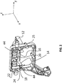
- the FIG. 1 shows a perspective view of a rear side of the swing frame 1 and the light module 10, while the FIG. 2 a perspective view of the front of the swing frame 1 and the light module 10 shows.
- the swing frame 1 has in the illustrated embodiment, a barrel-shaped bearing pin 2, a spherical bearing pin 3 and a receptacle 4 for a spherical bearing pin.
- the bearing journals 2, 3 and the receptacle 4 form articulation structures, with which the pivoting frame is mounted in its intended use in a motor vehicle headlight pivotally mounted in a housing of the motor vehicle headlight.
- the barrel-shaped journal 2 defines together with the spherical bearing pin 3 a pivot axis for a headlamp leveling and the spherical bearing pin 38 defines together with the receptacle 40 a pivot axis for a cornering light function.
- the pins 2, 3 and the receptacle 4 are not essential to the invention and are mentioned here only for a better understanding of the illustrated embodiment.
- the x-direction When used as intended, the x-direction will be approximately parallel to the vehicle's longitudinal axis, while the y-direction will be approximately parallel to the vehicle transverse axis and the z-direction approximately parallel to the vehicle's vertical axis.
- the light module 10 has a support shell 12, a reflection shell 14 and a circuit board 16 and, in the illustrated embodiment, is rigidly connected to the pivot frame 1 by a suitable connection.
- the suitable connection is preferably a screw connection or a riveted connection.
- FIG. 2 shows the subject of the FIG. 1 obliquely from the front, so that a reflection surface 18 of the reflection shell 14 can be seen.
- the reflection tray 14 has two reflector chambers in the illustrated embodiment, but this is not essential to the invention.
- a reflector of a light module 10 according to the invention may also have only one or even more than two reflector chambers.
- each semiconductor light source 20 has at least one light-emitting diode or laser diode or a field of light-emitting diodes or laser diodes.
- screw-on front opening 22 are used for screwing a diaphragm unit and / or a lens holder unit to the swing frame 1 of the light module 10.
- a diaphragm unit is used in particular for generating a light-dark boundary of a Low beam.
- the light module according to the invention would be part of a so-called projection light module, which images a diaphragm edge of said aperture as a sharp cut-off line.
- the light module can also be a directly imaging light module in which the reflector generates the light distribution directly from the light of the light sources, without the need for another optical element in the form of a lens or another reflector in the bundle of outgoing light from the reflection surface ,
- the closed fferendohme 25 visible in the lower half of the swing frame 1 serve to receive screws, with which a further light module, for example a high-beam module, is fastened to the swing frame 1 with a second reflector.
- a further light module for example a high-beam module
- FIGS. 3 to 5 show vertical cuts or, in the case of FIG. 5 a part of a vertical section through the object of FIGS. 1 and 2 ,
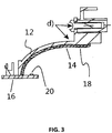
- FIG. 3 It shows the FIG. 3 a cut that in the FIG. 1 in the y-direction approximately in the middle of the light module 10 and parallel to the xz plane and in particular an attachment of the support shell 12 on the swing frame 1 shows.
- FIG. 3 shows in particular a support shell 12 with reflection shell 14 and the board 16 with a Semiconductor light source 20.
- the semiconductor light source 20 is a light-emitting diode, a field of a plurality of light-emitting diodes, a laser diode, or a field of a plurality of laser diodes.
- the support shell 12 is made of a first material, and a voltage applied to the support shell 12 reflection shell 14 is made of a second material. Support shell 12 and reflection shell 14 together form a reflector with reflection surface 18th
- the base material of the first material is preferably a light metal such as aluminum or magnesium or an alloy containing at least one of these light metals.
- a base material is characterized by good mechanical strength and good thermal conductivity. Its surface forms a thermally effective, that is heat absorbing and emitting to the environment surface of the reflector, or the light module 10.
- the second material is for example a plastic.
- This plastic then forms the base material of the optically effective reflection surface 18.
- the selection of this base material makes subsequent processes, such as painting, unnecessary. All in all, the division of the component functions on different materials allows the avoidance of systemic disadvantages of a reflector consisting of only one material, which in the prior art both the mechanical, thermal and optical Functions must meet.
- a plug element 26 arranged on the circuit board 16 serves for the electrical contacting and energy supply of the semiconductor light source 20.
- the support shell 12 of the reflector is fastened in the light module 10 by means of a screw 28, for example on a pivoting frame 1 of the light module 10.
- FIG. 4 shows a cross section through the light module 10 according to the invention, which runs parallel to the xz plane and which is approximately in the amount of a fastening screw, or a screw receiving this screw dome 32, with which the board 16 is connected to the reflection shell 14 and the support shell 12 , It shows FIG. 2 in particular a fferendohm 32 as part of the support shell 12 and a recess 34 in the board 16.
- the support shell 12 preferably has surface-enlarging structures 36 on its rear side facing away from the reflection shell 14. These surface enlarging structures 36 are preferred a form of ribs to deliver heat to the environment.
- the ribs preferably run parallel to the xz plane. With this arrangement, a better heat dissipation is achieved by the light emitting diode.
- This form offers over the alternative of pin-shaped cooling structures the advantage of having an additional stiffening effect, which makes it possible to use lightweight support shells 12 with comparatively little use of material.
- the support shell 12 has fastening elements 38 for fastening the circuit board 16.
- the fasteners 38 fferendohme 32nd
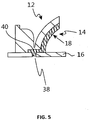
- FIG. 5 shows a parallel to the xz plane and in the vicinity of a y-directional side edge of the light module 10 lying cross-section through an inventive light module 10.
- FIG. 5 is the lateral edge of the in FIG. 1 left edge of the light module 10.
- the reflection shell 14 and the board 16 have mutually complementary and interlocking positioning structures 38, 40, which from the sectional plane of the FIG. 5 get cut.
- the positioning structures 38, 40 By means of the positioning structures 38, 40, the circuit board 16 and in particular a semiconductor light source 20 arranged on the circuit board 16 in an accuracy defined by the manufacturing accuracy of the positioning structures 38, 40 relative to the support shell 12 and Reflection shell 14 existing reflector 12 fixed.
- the positioning structures are preferably projections 38 in the reflection shell 14, which engage without play in corresponding, ie suitably dimensioned, recesses 40 of the board 16.
- the positioning structures can also be projections on the circuit board 16, which engage without play in recesses of the reflection shell 14 dimensioned to match them.
- Similar or identical positioning structures are preferably also or arranged in the circuit board 20 on its side facing the support shell 12 and in or on the support shell 12. These also engage each other without backlash so that the position of the support shell 12 with respect to the circuit board 16 and thus with respect to the light source (s) 20 is determined with high accuracy.
- Such positioning structures are preferably also in the vicinity of in the FIG. 1 arranged left edge of the light module.
- FIG. 2 shows that the support shell 12 at its light exit end in the clear width of the opening of the light exit side end protruding projections 44 has.
- each of these projections 44 each form a stop for a light exit side edge of the reflection tray 14.
- the support shell has at least two such projections 44, one of which from the right side and one from the left side protrudes into said opening and a stop in the sideways direction (y-direction and opposite direction) and a stop in the light exit direction (x-direction) forms.
- the support shell 12 and the reflection shell 14 are shaped and dimensioned to one another in the sense that a convex rear side of the reflection shell 14 facing away from the light exit side is snugly and free of play, preferably under slight prestressing, by a concave surface of the support shell.
Landscapes
- Engineering & Computer Science (AREA)
- General Engineering & Computer Science (AREA)
- Physics & Mathematics (AREA)
- Optics & Photonics (AREA)
- Microelectronics & Electronic Packaging (AREA)
- Non-Portable Lighting Devices Or Systems Thereof (AREA)
- Lighting Device Outwards From Vehicle And Optical Signal (AREA)
Abstract
Description
- Die vorliegende Erfindung betrifft ein Lichtmodul eines Kraftfahrzeugscheinwerfers, das einen Reflektor, einen Kühlkörper und eine Platine mit einer Halbleiterlichtquelle aufweist. Ein solches Lichtmodul ist per se bekannt.
- Reflektoren werden heute üblicherweise aus Kunststoffen wie Duroplast, Thermoplast oder aus metallischen Werkstoffen wie z. Bsp. Aluminium hergestellt. Diese Materialien werden in der Regel oberflächenbehandelt um optische Anforderungen zu erfüllen.
- Die zu erreichende Oberflächengenauigkeit ist stark von der Art der Oberflächenbehandlung abhängig, was bereits beim Entwurf des Lichtmoduls berücksichtigt werden muss. Derzeit sind teure Fertigungsmittel (z. Bsp. Lackieranlagen) notwendig um die Reflektor-Rohteile für die finale Oberflächenbehandlung aufzubereiten. Dabei müssen Prozessfenster vorgesehen werden, und deren Einhaltung muss überwacht werden, um Schwankungen der Qualität zu erfassen und einzuschränken. Je nach verwendetem Werkstoff bestehen Einschränkungen in der Gestaltung der Bauteile (durch die zur Herstellung notwendige Werkzeugtechnologie) wie z. Bsp. Einfallstellen, die durch Schrumpfung beim Abkühlen eines gegossenen Reflektors auftreten, Ungenauigkeiten durch geometrische Verzüge, Gratbildung etc.
- Durch die bauteileigenen und baugruppenabhängigen Toleranzen sind beim Entwurf Wirkungsgradverluste des Gesamtsystems zu berücksichtigen, was Kosten und Aufwand erhöht.
- Die zu erreichende Steifigkeit der Reflektoren ist je nach Werkstoff stark unterschiedlich und hat in der Vergangenheit zu erheblichen Problemen geführt. Die geforderte Güte der zu erreichenden optischen Fläche schränkt wiederum die Möglichkeiten der mechanischen Stabilisierung der Reflektoren stark ein.
- Zusätzlich sind in der Regel ein oder mehrere weitere Elemente zur Abführung der angefallenen Wärmeenergie und oder zur mechanischen Befestigung notwendig. Zur Wärmeabfuhr sind bedingt durch die Übertragungstechnologie Wirkungsgradverschlechterungen hinzunehmen. Mehrkosten durch Erhöhung des Materialeinsatzes sind notwendig.
- Vor diesem Hintergrund besteht die Aufgabe der Erfindung in der Angabe eines Lichtmoduls, das diese Nachteile nicht oder zumindest allenfalls nur in einem stark verringerten Umfang aufweist.
- Diese Aufgabe wird mit den Merkmalen des Anspruchs 1 gelöst. Das erfindungsgemäße Lichtmodul zeichnet sich dadurch aus, dass der Reflektor eine Stützschale aus einem ersten Material und eine an der Stützschale anliegende Reflexionsschale aus einem zweiten Material aufweist, wobei die Reflexionsschale und die Platine zueinander komplementäre und ineinander greifende Positionierungsstrukturen aufweisen und wobei die Stützschale mit der Platine durch eine geeignete Verbindung thermisch gekoppelt verbunden ist. Die geeignete Verbindung ist bevorzugt eine Schraubverbindung oder eine Nietverbindung.
- Durch diese Merkmale wird ein gleichzeitig sehr präzises und mechanisch belastbares Lichtmodul mit im Vergleich zum Stand der Technik verringertem Materialeinsatz bereitgestellt. Das erfindungsgemäße Lichtmodul weist einen optimierten Wirkungsgrad auf und zeichnet sich ferner durch eine reduzierte Bauraumforderung aus. Unter dem Wirkungsgrad wird dabei der auf den Lichtstrom der Lichtquellen normierte Lichtstrom verstanden, der von dem Lichtmodul in den Raumwinkel einer für Kraftfahrzeuge regelkonformen Lichtverteilung abgestrahlt wird.
- Für jede Komponente des Lichtmoduls erlaubt der modulare Aufbau eine Kombination mehrerer positiver Eigenschaften der Einzelwerkstoffe um ein effektives, kostengünstiges Bauteil mit hoher Formgenauigkeit zu schaffen welches ohne teure und aufwändige (qualitätsmindernde) Folgeprozesse die geforderte Oberflächenqualität liefert. Der modulare Aufbau führt zu dem Vorteil eine Reduzierung der Toleranzkette innerhalb des lichttechnischen Systems des Lichtmoduls. Als weiterer Vorteil ergibt sich die Möglichkeit einer Reduzierung des Gesamtgewichts des Lichtmoduls. Durch den Entfall von Prozessschritten im Fertigungsprozess, die bei einteiligen Reflektoren zur Erzielung der geforderten Oberflächengenauigkeit erforderlich sind, ergibt sich in der Fertigung eine Reduzierung von Kapitalbindung durch den Entfall von Maschinenanlagen. Der mögliche geringere Materialeinsatz erlaubt eine Verringerung des für den Einbau erforderlichen Bauraums im Scheinwerfer.
- Bevorzugt ist auch, dass die Halbleiterlichtquelle wenigstens eine Leuchtdiode oder Laserdiode oder ein Feld von Leuchtdioden oder Laserdioden aufweist.
- Ferner ist bevorzugt, dass der Grundwerkstoff des ersten Materials ein Leichtmetall wie Aluminium oder Magnesium oder eine wenigstens eines dieser Leichtmetalle enthaltende Legierung ist.
- Eine weitere bevorzugte Ausgestaltung zeichnet sich dadurch aus, dass das zweite Material ein Kunststoff ist.
- Bevorzugt ist auch, dass die Stützschale des Reflektors im Lichtmodul mit einem geeigneten Befestigungsmittel, bevorzugt mit einer Schraube, an einem Schwenkrahmen des Lichtmoduls befestigt ist.
- Ferner ist bevorzugt, dass die Reflexionsschale zwischen der Platine und der Stützschale eingeklemmt und damit befestigt ist.
- Eine weitere bevorzugte Ausgestaltung zeichnet sich dadurch aus, dass die oberflächenvergrößernden Strukturen eine Form von Rippen besitzen, um Wärme an die Umgebung abgeben zu können.
- Bevorzugt ist auch, dass die Reflexionsschale und die Platine zueinander komplementäre und ineinandergreifende Positionierungsstrukturen aufweisen.
- Ferner ist bevorzugt, dass die Positionierungsstrukturen Vorsprünge in der Reflexionsschale sind, die spielfrei in dazu korrespondierende, d.h. passend dimensionierte Ausnehmungen der Platine greifen, oder dass die Positionierungsstrukturen Vorsprünge auf der Platine sind, die spielfrei in dazu passend dimensionierte Ausnehmungen der Reflexionsschale greifen.
- Eine weitere bevorzugte Ausgestaltung zeichnet sich dadurch aus, dass ähnliche oder gleiche Positionierungsstrukturen auch auf, beziehungsweise in der Platine auf deren der Stützschale zugewandten Seite und in, beziehungsweise an der Stützschale angeordnet sind und so dimensioniert sind, dass sie spielfrei ineinander greifen.
- Bevorzugt ist auch, dass die Stützschale an ihrem lichtaustrittsseitigen Ende in die lichte Weite der Öffnung des lichtaustrittseitigen Endes hineinragende Vorsprünge aufweist.
- Ferner ist bevorzugt, dass die Stützschale wenigstens zwei solche Vorsprünge aufweist, von denen jeweils einer von der rechten Seite und einer von der linken Seite in die genannte Öffnung hineinragt und einen Anschlag in der Seitwärtsrichtung und einen Anschlag in der zur Seitwärtsrichtung senkrechten Lichtaustrittsrichtung bildet.
- Eine weitere bevorzugte Ausgestaltung zeichnet sich dadurch aus, dass die Stützschale und die Reflexionsschale in dem Sinne zueinander passend geformt und dimensioniert sind, dass eine konvexe, ihrer Lichtaustrittsseite abgewandte Rückseite der Reflexionsschale passgenau und spielfrei durch eine konkave Fläche der Stützschale aufgenommen wird.
- Weitere Vorteile ergeben sich aus den abhängigen Ansprüchen, der Beschreibung und den beigefügten Figuren.
- Es versteht sich, dass die vorstehend genannten und die nachstehend noch zu erläuternden Merkmale nicht nur in der jeweils angegebenen Kombination, sondern auch in anderen Kombinationen oder in Alleinstellung verwendbar sind, ohne den Rahmen der vorliegenden Erfindung zu verlassen.
- Ausführungsbeispiele der Erfindung sind in den Zeichnungen dargestellt und werden in der nachfolgenden Beschreibung näher erläutert. Dabei bezeichnen gleiche Bezugszeichen in verschiedenen Figuren jeweils gleiche oder zumindest ihrer Funktion nach vergleichbare Elemente. Es zeigen, jeweils in schematischer Form:
- Figur 1
- einen Schwenkrahmen eines Kraftfahrzeugscheinwerfers mit einem erfindungsgemäßen Lichtmodul von schräg hinten;
- Figur 2
- den Gegenstand der
Figur 1 von schräg vorne; - Figur 3
- einen in der Mitte des Lichtmoduls parallel zur Hauptabstrahlrichtung liegenden vertikalen Querschnitt, der insbesondere eine Befestigung des Lichtmoduls an einem Schwenkrahmen zeigt;
- Figur 4
- einen dazu parallel liegenden Querschnitt durch das Lichtmodul, der in der Höhe einer Befestigungsschraube liegt, mit der die Platine mit der Reflektorschale und der Stützschale verbunden ist; und
- Figur 5
- einen in der Nähe zweiten seitlichen Randes des Lichtmoduls liegenden Querschnitts des Lichtmoduls.
- Im Einzelnen zeigen die
Figuren 1 und2 einen Schwenkrahmen 1 eines Kraftfahrzeugscheinwerfers, der ein Bestandteil eines Ausführungsbeispiels eines erfindungsgemäßen Lichtmoduls 10 ist. DieFigur 1 zeigt dabei eine perspektivische Ansicht einer Rückseite des Schwenkrahmens 1 und des Lichtmoduls 10, während dieFigur 2 eine perspektivische Ansicht der Vorderseite des Schwenkrahmens 1 und des Lichtmoduls 10 zeigt. - Der Schwenkrahmen 1 weist in dem dargestellten Ausführungsbeispiel einen tonnenförmigen Lagerzapfen 2, einen kugelförmigen Lagerzapfen 3 und eine Aufnahme 4 für einen kugelförmigen Lagerzapfen auf. Die Lagerzapfen 2, 3 und die Aufnahme 4 bilden Anlenkstrukturen, mit denen der Schwenkrahmen bei seiner bestimmungsgemäßen Verwendung in einem Kraftfahrzeugscheinwerfer schwenkbar in einem Gehäuse des Kraftfahrzeugscheinwerfers gelagert ist. Der tonnenförmige Lagerzapfen 2 definiert zusammen mit dem kugelförmigen Lagerzapfen 3 eine Schwenkachse für eine Leuchtweitenregelung und der kugelförmige Lagerzapfen 38 definiert zusammen mit der Aufnahme 40 eine Schwenkachse für eine Kurvenlichtfunktion. Die Zapfen 2, 3 und die Aufnahme 4 sind für die Erfindung nicht wesentlich und werden hier lediglich zum besseren Verständnis der dargestellten Ausgestaltung erwähnt.
- Bei der bestimmungsgemäßen Verwendung wird die x-Richtung etwa parallel zur Fahrzeuglängsachse liegen, während die y-Richtung etwa parallel zur Fahrzeugquerachse und die z-Richtung etwa parallel zur Fahrzeughochachse liegen wird.
- Das Lichtmodul 10 weist eine Stützschale 12, eine Reflexionsschale 14 und eine Platine 16 auf und ist in der dargestellten Ausgestaltung durch eine geeignete Verbindung starr mit dem Schwenkrahmen 1 verbunden. Die geeignete Verbindung ist bevorzugt eine Schraubverbindung oder eine Nietverbindung.
-
Figur 2 zeigt den Gegenstand derFigur 1 schräg von vorne, so dass eine Reflexionsfläche 18 der Reflexionsschale 14 erkennbar ist. Die Reflexionsschale 14 weist in der dargestellten Ausgestaltung zwei Reflektorkammern auf, was aber für die Erfindung nicht wesentlich ist. Ein Reflektor eines erfindungsgemäßen Lichtmoduls 10 kann auch nur eine oder auch mehr als zwei Reflektorkammern aufweisen. - In den
Figuren 1 und2 ist auch die Platine 16 zu sehen. Auf der in derFigur 2 sichtbaren Seite der Platine 16, die der Reflexionsfläche 18 zugewandt ist, ist jeweils eine Halbleiterlichtquelle 20 für jede Reflektorkammer sichtbar. Jede Halbleiterlichtquelle 20 weist wenigstens eine Leuchtdiode oder Laserdiode oder ein Feld von Leuchtdioden oder Laserdioden auf. - Die der
Figur 2 nach vorne offenen Schraubendohme 22 dienen zum Beispiel zum Anschrauben einer Blendeneinheit und/oder einer Linsenhaltereinheit an den Schwenkrahmen 1 des Lichtmoduls 10. Eine Blendeneinheit dient insbesondere zur Erzeugung einer Hell-Dunkel-Grenze einer Abblendlichtverteilung. Bei einer solchen Ausgestaltung wäre das erfindungsgemäße Lichtmodul ein Bestandteil eines sogenannten Projektionslichtmoduls, das eine Blendenkante der genannten Blende als scharfe Hell-Dunkel-Grenze abbildet. Das Lichtmodul kann aber auch ein direkt abbildendes Lichtmodul sein, bei dem der Reflektor die Lichtverteilung direkt aus dem Licht der Lichtquellen erzeugt, ohne dass dazu ein weiteres optisches Element in Form einer Linse oder eines weiteren Reflektors im Bündel des von der Reflexionsfläche ausgehenden Lichtes erforderlich ist. - Die in der oberen Hälfte des Schwenkrahmens 1 sichtbaren geschlossenen Schraubendohme 24 dienen zur Aufnahme von Schrauben, mit denen die Stützschale 12 an den Schwenkrahmen 1 angeschraubt ist.
- Die in der unteren Hälfte des Schwenkrahmens 1 sichtbaren geschlossenen Schraubendohme 25 dienen zur Aufnahme von Schrauben, mit denen ein weiteres Lichtmodul, zum Beispiel ein Fernlichtmodul, mit einem zweiten Reflektor an dem Schwenkrahmen 1 befestigt wird.
- Die
Figuren 3 bis 5 zeigen vertikale Schnitte oder, im Fall derFigur 5 einen Teil eines vertikalen Schnitts durch den Gegenstand derFiguren 1 und2 . - Dabei zeigt die
Figur 3 einen Schnitt, der in derFigur 1 in der y-Richtung etwa in der Mitte des Lichtmoduls 10 und parallel zur x-z-Ebene liegt und insbesondere eine Befestigung der Stützschale 12 am Schwenkrahmen 1 zeigt. -
Figur 3 zeigt insbesondere eine Stützschale 12 mit Reflexionsschale 14 und die Platine 16 mit einer Halbleiterlichtquelle 20. Bei der Halbleiterlichtquelle 20 handelt es sich um eine Leuchtdiode, ein Feld aus mehreren Leuchtdioden, eine Laserdiode, oder ein Feld aus mehreren Laserdioden. - Die Stützschale 12 besteht aus einem ersten Material, und eine an der Stützschale 12 anliegende Reflexionsschale 14 besteht aus einem zweiten Material. Stützschale 12 und Reflexionsschale 14 bilden zusammen einen Reflektor mit Reflexionsfläche 18.
- Der Grundwerkstoff des ersten Materials ist bevorzugt ein Leichtmetall wie Aluminium oder Magnesium oder eine wenigstens eines dieser Leichtmetalle enthaltende Legierung. Ein solcher Grundwerkstoff zeichnet sich durch eine gute mechanische Festigkeit und eine gute Wärmeleitfähigkeit aus. Seine Oberfläche bildet eine thermisch wirksame, das heißt Wärme aufnehmende und an die Umgebung abgebende Oberfläche des Reflektors, bzw. des Lichtmoduls 10. Durch die Auswahl dieses Grundwerkstoffes der thermisch wirksamen Oberfläche wird die Effektivität des Gesamtsystems erhöht, unter der hier die Effektivität einer Wärmeabfuhr aus den Lichtquellen und der Platine gemeint ist.
- Das zweite Material ist zum Beispiel ein Kunststoff. Dieser Kunststoff bildet dann den Grundwerkstoff der optisch wirksamen Reflexionsfläche 18. Durch die Auswahl dieses Grundwerkstoffes werden Folgeprozesse, wie zum Beispiel ein Lackieren, unnötig. Alles in allem erlaubt die Aufteilung der Bauteilfunktionen auf unterschiedliche Werkstoffe die Vermeidung systembedingter Nachteile eines nur aus einem Material bestehenden Reflektors, der beim Stand der Technik sowohl die mechanischen, thermischen und optischen Funktionen erfüllen muss.
- Ein auf der Platine 16 angeordnetes Steckerelement 26 dient zur elektrischen Kontaktierung und Energieversorgung der Halbleiterlichtquelle 20. Mit einer Schraube 28 ist die Stützschale 12 des Reflektors im Lichtmodul 10 befestigt, zum Beispiel an einem Schwenkrahmen 1 des Lichtmoduls 10.
-
Figur 4 zeigt einen Querschnitt durch das erfindungsgemäße Lichtmodul 10, der parallel zur x-z-Ebene verläuft und der etwa in der Höhe einer Befestigungsschraube, bzw. eines diese Schraube aufnehmenden Schraubendoms 32 liegt, mit denen die Platine 16 mit der Reflexionsschale 14 und der Stützschale 12 verbunden ist. Dabei zeigtFigur 2 insbesondere einen Schraubendohm 32 als Bestandteil der Stützschale 12 und eine Ausnehmung 34 in der Platine 16. Durch Eindrehen einer durch die Ausnehmung hindurch in den Schraubendohm 32 eingesetzten Schraube und Festziehen der Schraube wird die Platine 16 mit der Stützschale 12 mechanisch fest verbunden. Dabei wird die Reflexionsschale 14 zwischen der Platine 16 und der Stützschale 12 eingeklemmt und damit befestigt. - Über den Befestigungseffekt hinaus ergibt sich auch eine thermische Kopplung zwischen Halbleiterlichtquelle 20, Platine 16 und Stützschale 12, über die in der Halbleiterlichtquelle 20 erzeugte Wärme aus der Platine 16 heraus in die bevorzugt auch als Kühlkörper dienende Stützschale 12 abgeleitet wird.
- Zur Abgabe der Wärme an die Umgebung weist die Stützschale 12 auf ihrer der Reflexionsschale 14 abgewandten Rückseite bevorzugt oberflächenvergrößernde Strukturen 36 auf. Diese oberflächenvergrößernden Strukturen 36 besitzen bevorzugt eine Form von Rippen, um Wärme an die Umgebung abgeben zu können. Die Rippen verlaufen bevorzugt parallel zu der x-z-Ebene. Mit dieser Anordnung wird eine bessere Wärmeabfuhr von der Leuchtdiode erreicht. Diese Form bietet gegenüber der Alternative von stiftförmigen Kühlstrukturen den Vorteil, auch eine zusätzliche versteifende Wirkung zu besitzen, was es erlaubt, leichte Stützschalen 12 mit vergleichsweise wenig Materialeinsatz zu verwenden.
- Neben diesen angeformten Versteifungsstrukturen 36 weist die Stützschale 12 Befestigungselemente 38 zur Befestigung der Platine 16 auf. In der dargestellten Ausgestaltung sind die Befestigungselemente 38 Schraubendohme 32.
-
Figur 5 zeigt einen parallel zur x-z-Ebene und in der Nähe eines in y-Richtung seitlichen Randes des Lichtmoduls 10 liegenden Querschnitt durch ein erfindungsgemäßes Lichtmodul 10. Im Fall derFigur 5 ist der seitliche Rand der inFigur 1 linke Rand des Lichtmoduls 10. Die Reflexionsschale 14 und die Platine 16 weisen zueinander komplementäre und ineinandergreifende Positionierungsstrukturen 38, 40 auf, die von der Schnittebene derFigur 5 geschnitten werden. - Es ist bevorzugt, dass weitere Positionierungsgeometrien vorhanden sind. Es ist insbesondere bevorzugt, dass auch in der Nähe des rechten Randes des Lichtmoduls 10 solche oder ähnliche Positionierungsgeometrien angeordnet sind.
- Durch die Positionierungsstrukturen 38, 40 wird die Platine 16 und insbesondere eine auf der Platine 16 angeordnete Halbleiterlichtquelle 20 in einer durch die Fertigungsgenauigkeit der Positionierungsstrukturen 38, 40 definierten Genauigkeit relativ zum aus Stützschale 12 und Reflexionsschale 14 bestehenden Reflektor 12 fixiert. Die Positionierungsstrukturen sind bevorzugt Vorsprünge 38 in der Reflexionsschale 14, die spielfrei in dazu korrespondierende, d.h. passend dimensionierte Ausnehmungen 40 der Platine 16 greifen. Umgekehrt können die Positionierungsstrukturen auch Vorsprünge auf der Platine 16 sein, die spielfrei in dazu passend dimensionierte Ausnehmungen der Reflexionsschale 14 greifen.
- Ähnliche oder gleiche Positionierungsstrukturen sind bevorzugt auch, beziehungsweise in der Platine 20 auf deren der Stützschale 12 zugewandten Seite und in, beziehungsweise an der Stützschale 12 angeordnet. Auch diese greifen spielfrei so ineinander, dass die Position der Stützschale 12 in Bezug auf die Leiterplatte 16 und damit in Bezug auf die Lichtquelle(n) 20 hochgenau festgelegt ist.
- Solche Positionierungsstrukturen sind bevorzugt auch in der Nähe des in der
Figur 1 linken Randes des Lichtmoduls angeordnet. -
Figur 2 zeigt, dass die Stützschale 12 an ihrem lichtaustrittsseitigen Ende in die lichte Weite der Öffnung des lichtaustrittseitigen Endes hineinragende Vorsprünge 44 aufweist. Beim Einsetzen der Reflexionsschale 14 in die Stützschale 12 bilden jeder dieser Vorsprünge 44 jeweils einen Anschlag für einen lichtaustrittsseitigen Rand der Reflexionsschale 14. Bevorzugt weist die Stützschale wenigstens zwei solche Vorsprünge 44 auf, von denen jeweils einer von der rechten Seite und einer von der linken Seite in die genannte Öffnung hineinragt und einen Anschlag in der Seitwärtsrichtung (y-Richtung und Gegenrichtung) und einen Anschlag in der Lichtaustrittsrichtung (x-Richtung) bildet. - Die Stützschale 12 und die Reflexionsschale 14 sind in dem Sinne zueinander passend geformt und dimensioniert, dass eine konvexe, ihrer Lichtaustrittsseite abgewandte Rückseite der Reflexionsschale 14 passgenau und spielfrei, bevorzugt unter leichter Vorspannung, durch eine konkave Fläche der Stützschale aufgenommen wird.
- Durch diese Art der Verbindung von Reflexionsschale 14, Platine 16 mit Lichtquellen 20 und Stützschale 12 wird eine Reduzierung der Toleranzkette innerhalb eines lichttechnischen Systems möglich.
Claims (15)
- Lichtmodul (10) eines Kraftfahrzeugscheinwerfers, das einen Reflektor, einen Kühlkörper und eine Platine (16) mit einer Halbleiterlichtquelle (20) aufweist, dadurch gekennzeichnet, dass der Reflektor eine Stützschale (12) aus einem ersten Material und eine an der Stützschale (12) anliegende Reflexionsschale (14) aus einem zweiten Material aufweist, wobei die Reflexionsschale (14) und die Platine (16) zueinander komplementäre und ineinander greifende Positionierungsstrukturen aufweisen und wobei die Stützschale mit der Platine durch eine geeignete Verbindung thermisch gekoppelt verbunden ist.
- Lichtmodul (10) nach Anspruch 1, dadurch gekennzeichnet, dass die Halbleiterlichtquelle 20 wenigstens eine Leuchtdiode oder Laserdiode oder ein Feld von Leuchtdioden oder Laserdioden aufweist.
- Lichtmodul (10) nach einem der vorhergehenden Ansprüche, dadurch gekennzeichnet, dass der Grundwerkstoff des ersten Materials ein Leichtmetall wie Aluminium oder Magnesium oder eine wenigstens eines dieser Leichtmetalle enthaltende Legierung ist.
- Lichtmodul (10) nach einem der vorhergehenden Ansprüche, dadurch gekennzeichnet, dass das zweite Material ein Kunststoff ist.
- Lichtmodul (10) nach einem der vorhergehenden Ansprüche, dadurch gekennzeichnet, dass die Stützschale (12) des Reflektors im Lichtmodul (10) mit einem geeigneten Befestigungsmittel an einem Schwenkrahmen (1) des Lichtmoduls (10) befestigt ist.
- Lichtmodul (10) nach einem der vorhergehenden Ansprüche, dadurch gekennzeichnet, dass die Reflexionsschale (14) zwischen der Platine (16) und der Stützschale (12) eingeklemmt und damit befestigt ist oder auch in der Reflexionsschale befestigt ist.
- Lichtmodul (10) nach einem der vorhergehenden Ansprüche, dadurch gekennzeichnet, dass die Stützschale (12) auf ihrer der Reflexionsschale (14) abgewandten Rückseite oberflächenvergrößernde Strukturen (36) aufweist.
- Lichtmodul (10) nach Anspruch 7, dadurch gekennzeichnet, dass die oberflächenvergrößernden Strukturen (36) eine Kühlrippenform oder ein Stiftform besitzen.
- Lichtmodul (10) nach einem der vorhergehenden Ansprüche, dadurch gekennzeichnet, dass die Reflexionsschale (14) und die Platine (16) zueinander komplementäre und ineinandergreifende Positionierungsstrukturen (38, 40) aufweisen.
- Lichtmodul (10) nach Anspruch 9, dadurch gekennzeichnet, dass die Positionierungsstrukturen Vorsprünge (38) in der Reflexionsschale (14) sind, die spielfrei in dazu korrespondierende, d.h. passend dimensionierte Ausnehmungen (40) der Platine (16) greifen, oder dass die Positionierungsstrukturen Vorsprünge auf der Platine (16) sind, die spielfrei in dazu passend dimensionierte Ausnehmungen der Reflexionsschale (14) greifen.
- Lichtmodul (10) nach Anspruch 10, dadurch gekennzeichnet, dass ähnliche oder gleiche Positionierungsstrukturen auch auf, beziehungsweise in der Platine (20) auf deren der Stützschale 12 zugewandten Seite und in, beziehungsweise an der Stützschale (12) angeordnet sind und so dimensioniert sind, dass sie spielfrei ineinander greifen.
- Lichtmodul (10) nach einem der vorhergehenden Ansprüche, dadurch gekennzeichnet, dass die Stützschale (12) an ihrem lichtaustrittsseitigen Ende in die lichte Weite der Öffnung des lichtaustrittseitigen Endes hineinragende Vorsprünge 44 aufweist.
- Lichtmodul (10) nach Anspruch 12, dadurch gekennzeichnet, dass die Stützschale wenigstens zwei solche Vorsprünge (44) aufweist, von denen jeweils einer von der rechten Seite und einer von der linken Seite in die genannte Öffnung hineinragt und einen Anschlag in der Seitwärtsrichtung und einen Anschlag in der zur Seitwärtsrichtung senkrechten Lichtaustrittsrichtung bildet.
- Lichtmodul (10) nach einem der vorhergehenden Ansprüche, dadurch gekennzeichnet, dass die Stützschale (12) und die Reflexionsschale (14) in dem Sinne zueinander passend geformt und dimensioniert sind, dass eine konvexe, ihrer Lichtaustrittsseite abgewandte Rückseite der Reflexionsschale (14) passgenau und spielfrei durch eine konkave Fläche der Stützschale aufgenommen wird.
- Lichtmodul nach einem der vorhergehenden Ansprüche, dadurch gekennzeichnet, dass die geeignete Verbindung eine Schraubverbindung oder eine Nietverbindung ist.
Applications Claiming Priority (1)
| Application Number | Priority Date | Filing Date | Title |
|---|---|---|---|
| DE202016103680.1U DE202016103680U1 (de) | 2016-07-08 | 2016-07-08 | Mehrkomponentenreflektor für Lichtmodul eines Kraftfahrzeugscheinwerfers |
Publications (3)
| Publication Number | Publication Date |
|---|---|
| EP3270043A1 true EP3270043A1 (de) | 2018-01-17 |
| EP3270043B1 EP3270043B1 (de) | 2021-03-03 |
| EP3270043B9 EP3270043B9 (de) | 2021-07-14 |
Family
ID=59091329
Family Applications (1)
| Application Number | Title | Priority Date | Filing Date |
|---|---|---|---|
| EP17175679.4A Not-in-force EP3270043B9 (de) | 2016-07-08 | 2017-06-13 | Mehrkomponentenreflektor für lichtmodul eines kraftfahrzeugscheinwerfers |
Country Status (3)
| Country | Link |
|---|---|
| EP (1) | EP3270043B9 (de) |
| CN (1) | CN107588395B (de) |
| DE (1) | DE202016103680U1 (de) |
Families Citing this family (3)
| Publication number | Priority date | Publication date | Assignee | Title |
|---|---|---|---|---|
| DE202016103680U1 (de) * | 2016-07-08 | 2017-10-12 | Automotive Lighting Reutlingen Gmbh | Mehrkomponentenreflektor für Lichtmodul eines Kraftfahrzeugscheinwerfers |
| DE102019108233A1 (de) * | 2019-03-29 | 2020-10-01 | Automotive Lighting Reutlingen Gmbh | Lichtmodul für einen Kraftfahrzeugscheinwerfer mit n in einer Reihe nebeneinander angeordneten Teillichtmodulen |
| DE102023136305A1 (de) * | 2023-12-21 | 2025-06-26 | HELLA GmbH & Co. KGaA | Lichtmodul für eine Kraftfahrzeug-Beleuchtungseinrichtung |
Citations (5)
| Publication number | Priority date | Publication date | Assignee | Title |
|---|---|---|---|---|
| EP2163814A1 (de) * | 2008-09-16 | 2010-03-17 | Hella KG Hueck & Co. | Reflektor für eine Beleuchtungsvorrichtung eines Kraftfahrzeugs sowie Herstellungsverfahren |
| EP2366938A1 (de) * | 2010-03-01 | 2011-09-21 | Ichiko Industries, Ltd. | Fahrzeugbeleuchtungsvorrichtung |
| US20120182750A1 (en) * | 2011-01-14 | 2012-07-19 | Yao-Te Chung | Vehicular Lamp |
| EP2589479A2 (de) * | 2011-11-02 | 2013-05-08 | Zizala Lichtsysteme GmbH | Verfahren zur Herstellung von Reflektoren |
| WO2014056012A1 (de) * | 2012-10-09 | 2014-04-17 | Zizala Lichtsysteme Gmbh | Lichtmodul mit zwei oder mehr reflektoren für ein kraftfahrzeug |
Family Cites Families (2)
| Publication number | Priority date | Publication date | Assignee | Title |
|---|---|---|---|---|
| TWM326615U (en) * | 2007-06-01 | 2008-02-01 | Liang-Yung Huang | Installment to gain more brightness for tube lamp |
| DE202016103680U1 (de) * | 2016-07-08 | 2017-10-12 | Automotive Lighting Reutlingen Gmbh | Mehrkomponentenreflektor für Lichtmodul eines Kraftfahrzeugscheinwerfers |
-
2016
- 2016-07-08 DE DE202016103680.1U patent/DE202016103680U1/de not_active Expired - Lifetime
-
2017
- 2017-06-13 EP EP17175679.4A patent/EP3270043B9/de not_active Not-in-force
- 2017-07-07 CN CN201710549358.3A patent/CN107588395B/zh not_active Expired - Fee Related
Patent Citations (5)
| Publication number | Priority date | Publication date | Assignee | Title |
|---|---|---|---|---|
| EP2163814A1 (de) * | 2008-09-16 | 2010-03-17 | Hella KG Hueck & Co. | Reflektor für eine Beleuchtungsvorrichtung eines Kraftfahrzeugs sowie Herstellungsverfahren |
| EP2366938A1 (de) * | 2010-03-01 | 2011-09-21 | Ichiko Industries, Ltd. | Fahrzeugbeleuchtungsvorrichtung |
| US20120182750A1 (en) * | 2011-01-14 | 2012-07-19 | Yao-Te Chung | Vehicular Lamp |
| EP2589479A2 (de) * | 2011-11-02 | 2013-05-08 | Zizala Lichtsysteme GmbH | Verfahren zur Herstellung von Reflektoren |
| WO2014056012A1 (de) * | 2012-10-09 | 2014-04-17 | Zizala Lichtsysteme Gmbh | Lichtmodul mit zwei oder mehr reflektoren für ein kraftfahrzeug |
Also Published As
| Publication number | Publication date |
|---|---|
| CN107588395B (zh) | 2022-02-11 |
| CN107588395A (zh) | 2018-01-16 |
| DE202016103680U1 (de) | 2017-10-12 |
| EP3270043B1 (de) | 2021-03-03 |
| EP3270043B9 (de) | 2021-07-14 |
Similar Documents
| Publication | Publication Date | Title |
|---|---|---|
| EP2820348B1 (de) | Beleuchtungseinrichtung | |
| EP2744686B1 (de) | Scheinwerfer für ein kraftfahrzeug mit einer auswechselbaren komplexen lichtquelle | |
| EP2317213B1 (de) | Leuchtdiodenmodul einer Kraftfahrzeugbeleuchtungseinrichtung und Kraftfahrzeugbeleuchtungseinrichtung | |
| EP2693109B1 (de) | Lichtmodul | |
| DE102012213844B4 (de) | Lichtmodul für KFZ-Scheinwerfer mit zwei Optikeinheiten und zugehörigen Befestigungseinrichtungen | |
| AT518098B1 (de) | Zusatzscheinwerfer für Fahrzeuge sowie Scheinwerfersystem | |
| DE102015215696B4 (de) | Fahrzeugbeleuchtungseinrichtung | |
| EP2928726B1 (de) | Zusatzlichtmodul für einen scheinwerfer eines fahrzeugs | |
| DE102010009640A1 (de) | Frontscheinwerfer mit einem LED-Reflexionssystem mit Nebellicht- und Tagfahrlichtfunktion | |
| DE102008061431A1 (de) | Fahrzeugleuchte und Verfahren zur Herstellung derselben | |
| DE102004020493B4 (de) | Lichtverteilungsbaugruppe mit einer Vielzahl von Modulen | |
| DE202014104049U1 (de) | Positionierungssystem für eine optische Linse | |
| DE102015206755B4 (de) | Fahrzeugleuchte | |
| EP2484959A2 (de) | Modular aufgebautes Projektionslichtmodul eines Kraftfahrzeugscheinwerfers | |
| DE102021201873A1 (de) | Reflektor, leuchte, werkzeug, fahrzeug und verfahren zur herstellung einer leuchte | |
| EP3270043B1 (de) | Mehrkomponentenreflektor für lichtmodul eines kraftfahrzeugscheinwerfers | |
| DE102022108281B4 (de) | Lichtmodul und Kraftfahrzeugbeleuchtungseinrichtung mit einem solchen Lichtmodul | |
| DE202018107292U1 (de) | LED-Scheinwerfermodul und LED-Lichtmodul zur Verwendung in einem solchen LED-Scheinwerfermodul | |
| EP4204733B1 (de) | Kraftfahrzeugscheinwerfer | |
| DE102006021973A1 (de) | Leuchte mit wenigstens einer Leuchtmitteleinheit für Fahrzeuge, vorzugsweise für Kraftfahrzeuge | |
| DE102015204961B4 (de) | Projektionslichtmodul für einen Kraftfahrzeugscheinwerfer, aufweisend einen Festkörper mit einer Lichteintrittsfläche an einer Ausstülpung, zwei Lichtumlenkflächen, einer Blendenkante, einer Blendenfläche und zwei disjunkten Lichtaustrittsteilflächen | |
| DE102017110876A1 (de) | Lichtmodul eines Kraftfahrzeugscheinwerfers und Kraftfahrzeugscheinwerfer mit einem solchen Lichtmodul | |
| WO2013107445A1 (de) | Lichtmodul für scheinwerfer, insbesondere von schienenfahrzeugen, lichtleitkörper für ein solches lichtmodul und scheinwerfer mit einem solchen lichtmodul | |
| DE102021129189A1 (de) | Lichtmodul, Kühlkörper für Lichtmodul und Verfahren zum Herstellen eines Kühlkörpers | |
| DE102022108283B4 (de) | Lichtmodul, Kraftfahrzeugbeleuchtungseinrichtung mit einem solchen Lichtmodul und Verfahren zur Montage eines optischen Systems eines Lichtmoduls an einem Lichtquellenmodul des Lichtmoduls |
Legal Events
| Date | Code | Title | Description |
|---|---|---|---|
| PUAI | Public reference made under article 153(3) epc to a published international application that has entered the european phase |
Free format text: ORIGINAL CODE: 0009012 |
|
| STAA | Information on the status of an ep patent application or granted ep patent |
Free format text: STATUS: THE APPLICATION HAS BEEN PUBLISHED |
|
| AK | Designated contracting states |
Kind code of ref document: A1 Designated state(s): AL AT BE BG CH CY CZ DE DK EE ES FI FR GB GR HR HU IE IS IT LI LT LU LV MC MK MT NL NO PL PT RO RS SE SI SK SM TR |
|
| AX | Request for extension of the european patent |
Extension state: BA ME |
|
| STAA | Information on the status of an ep patent application or granted ep patent |
Free format text: STATUS: REQUEST FOR EXAMINATION WAS MADE |
|
| 17P | Request for examination filed |
Effective date: 20180717 |
|
| RBV | Designated contracting states (corrected) |
Designated state(s): AL AT BE BG CH CY CZ DE DK EE ES FI FR GB GR HR HU IE IS IT LI LT LU LV MC MK MT NL NO PL PT RO RS SE SI SK SM TR |
|
| REG | Reference to a national code |
Ref country code: DE Ref legal event code: R079 Ref document number: 502017009542 Country of ref document: DE Free format text: PREVIOUS MAIN CLASS: F21S0041370000 Ipc: F21S0045470000 |
|
| GRAP | Despatch of communication of intention to grant a patent |
Free format text: ORIGINAL CODE: EPIDOSNIGR1 |
|
| STAA | Information on the status of an ep patent application or granted ep patent |
Free format text: STATUS: GRANT OF PATENT IS INTENDED |
|
| RIC1 | Information provided on ipc code assigned before grant |
Ipc: F21S 45/47 20180101AFI20201007BHEP |
|
| INTG | Intention to grant announced |
Effective date: 20201111 |
|
| GRAS | Grant fee paid |
Free format text: ORIGINAL CODE: EPIDOSNIGR3 |
|
| GRAA | (expected) grant |
Free format text: ORIGINAL CODE: 0009210 |
|
| STAA | Information on the status of an ep patent application or granted ep patent |
Free format text: STATUS: THE PATENT HAS BEEN GRANTED |
|
| AK | Designated contracting states |
Kind code of ref document: B1 Designated state(s): AL AT BE BG CH CY CZ DE DK EE ES FI FR GB GR HR HU IE IS IT LI LT LU LV MC MK MT NL NO PL PT RO RS SE SI SK SM TR |
|
| REG | Reference to a national code |
Ref country code: GB Ref legal event code: FG4D Free format text: NOT ENGLISH |
|
| REG | Reference to a national code |
Ref country code: AT Ref legal event code: REF Ref document number: 1367612 Country of ref document: AT Kind code of ref document: T Effective date: 20210315 Ref country code: CH Ref legal event code: EP |
|
| REG | Reference to a national code |
Ref country code: DE Ref legal event code: R096 Ref document number: 502017009542 Country of ref document: DE |
|
| REG | Reference to a national code |
Ref country code: IE Ref legal event code: FG4D Free format text: LANGUAGE OF EP DOCUMENT: GERMAN |
|
| REG | Reference to a national code |
Ref country code: CH Ref legal event code: PK Free format text: BERICHTIGUNG B9 |
|
| REG | Reference to a national code |
Ref country code: LT Ref legal event code: MG9D |
|
| PG25 | Lapsed in a contracting state [announced via postgrant information from national office to epo] |
Ref country code: BG Free format text: LAPSE BECAUSE OF FAILURE TO SUBMIT A TRANSLATION OF THE DESCRIPTION OR TO PAY THE FEE WITHIN THE PRESCRIBED TIME-LIMIT Effective date: 20210603 Ref country code: LT Free format text: LAPSE BECAUSE OF FAILURE TO SUBMIT A TRANSLATION OF THE DESCRIPTION OR TO PAY THE FEE WITHIN THE PRESCRIBED TIME-LIMIT Effective date: 20210303 Ref country code: NO Free format text: LAPSE BECAUSE OF FAILURE TO SUBMIT A TRANSLATION OF THE DESCRIPTION OR TO PAY THE FEE WITHIN THE PRESCRIBED TIME-LIMIT Effective date: 20210603 Ref country code: HR Free format text: LAPSE BECAUSE OF FAILURE TO SUBMIT A TRANSLATION OF THE DESCRIPTION OR TO PAY THE FEE WITHIN THE PRESCRIBED TIME-LIMIT Effective date: 20210303 Ref country code: FI Free format text: LAPSE BECAUSE OF FAILURE TO SUBMIT A TRANSLATION OF THE DESCRIPTION OR TO PAY THE FEE WITHIN THE PRESCRIBED TIME-LIMIT Effective date: 20210303 Ref country code: GR Free format text: LAPSE BECAUSE OF FAILURE TO SUBMIT A TRANSLATION OF THE DESCRIPTION OR TO PAY THE FEE WITHIN THE PRESCRIBED TIME-LIMIT Effective date: 20210604 |
|
| REG | Reference to a national code |
Ref country code: NL Ref legal event code: MP Effective date: 20210303 |
|
| PG25 | Lapsed in a contracting state [announced via postgrant information from national office to epo] |
Ref country code: SE Free format text: LAPSE BECAUSE OF FAILURE TO SUBMIT A TRANSLATION OF THE DESCRIPTION OR TO PAY THE FEE WITHIN THE PRESCRIBED TIME-LIMIT Effective date: 20210303 Ref country code: PL Free format text: LAPSE BECAUSE OF FAILURE TO SUBMIT A TRANSLATION OF THE DESCRIPTION OR TO PAY THE FEE WITHIN THE PRESCRIBED TIME-LIMIT Effective date: 20210303 Ref country code: RS Free format text: LAPSE BECAUSE OF FAILURE TO SUBMIT A TRANSLATION OF THE DESCRIPTION OR TO PAY THE FEE WITHIN THE PRESCRIBED TIME-LIMIT Effective date: 20210303 Ref country code: LV Free format text: LAPSE BECAUSE OF FAILURE TO SUBMIT A TRANSLATION OF THE DESCRIPTION OR TO PAY THE FEE WITHIN THE PRESCRIBED TIME-LIMIT Effective date: 20210303 |
|
| PG25 | Lapsed in a contracting state [announced via postgrant information from national office to epo] |
Ref country code: NL Free format text: LAPSE BECAUSE OF FAILURE TO SUBMIT A TRANSLATION OF THE DESCRIPTION OR TO PAY THE FEE WITHIN THE PRESCRIBED TIME-LIMIT Effective date: 20210303 |
|
| PG25 | Lapsed in a contracting state [announced via postgrant information from national office to epo] |
Ref country code: SM Free format text: LAPSE BECAUSE OF FAILURE TO SUBMIT A TRANSLATION OF THE DESCRIPTION OR TO PAY THE FEE WITHIN THE PRESCRIBED TIME-LIMIT Effective date: 20210303 Ref country code: CZ Free format text: LAPSE BECAUSE OF FAILURE TO SUBMIT A TRANSLATION OF THE DESCRIPTION OR TO PAY THE FEE WITHIN THE PRESCRIBED TIME-LIMIT Effective date: 20210303 Ref country code: EE Free format text: LAPSE BECAUSE OF FAILURE TO SUBMIT A TRANSLATION OF THE DESCRIPTION OR TO PAY THE FEE WITHIN THE PRESCRIBED TIME-LIMIT Effective date: 20210303 |
|
| PG25 | Lapsed in a contracting state [announced via postgrant information from national office to epo] |
Ref country code: PT Free format text: LAPSE BECAUSE OF FAILURE TO SUBMIT A TRANSLATION OF THE DESCRIPTION OR TO PAY THE FEE WITHIN THE PRESCRIBED TIME-LIMIT Effective date: 20210705 Ref country code: RO Free format text: LAPSE BECAUSE OF FAILURE TO SUBMIT A TRANSLATION OF THE DESCRIPTION OR TO PAY THE FEE WITHIN THE PRESCRIBED TIME-LIMIT Effective date: 20210303 Ref country code: SK Free format text: LAPSE BECAUSE OF FAILURE TO SUBMIT A TRANSLATION OF THE DESCRIPTION OR TO PAY THE FEE WITHIN THE PRESCRIBED TIME-LIMIT Effective date: 20210303 Ref country code: IS Free format text: LAPSE BECAUSE OF FAILURE TO SUBMIT A TRANSLATION OF THE DESCRIPTION OR TO PAY THE FEE WITHIN THE PRESCRIBED TIME-LIMIT Effective date: 20210703 |
|
| REG | Reference to a national code |
Ref country code: DE Ref legal event code: R097 Ref document number: 502017009542 Country of ref document: DE |
|
| PLBE | No opposition filed within time limit |
Free format text: ORIGINAL CODE: 0009261 |
|
| STAA | Information on the status of an ep patent application or granted ep patent |
Free format text: STATUS: NO OPPOSITION FILED WITHIN TIME LIMIT |
|
| PG25 | Lapsed in a contracting state [announced via postgrant information from national office to epo] |
Ref country code: MC Free format text: LAPSE BECAUSE OF FAILURE TO SUBMIT A TRANSLATION OF THE DESCRIPTION OR TO PAY THE FEE WITHIN THE PRESCRIBED TIME-LIMIT Effective date: 20210303 Ref country code: DK Free format text: LAPSE BECAUSE OF FAILURE TO SUBMIT A TRANSLATION OF THE DESCRIPTION OR TO PAY THE FEE WITHIN THE PRESCRIBED TIME-LIMIT Effective date: 20210303 Ref country code: AL Free format text: LAPSE BECAUSE OF FAILURE TO SUBMIT A TRANSLATION OF THE DESCRIPTION OR TO PAY THE FEE WITHIN THE PRESCRIBED TIME-LIMIT Effective date: 20210303 Ref country code: ES Free format text: LAPSE BECAUSE OF FAILURE TO SUBMIT A TRANSLATION OF THE DESCRIPTION OR TO PAY THE FEE WITHIN THE PRESCRIBED TIME-LIMIT Effective date: 20210303 |
|
| REG | Reference to a national code |
Ref country code: CH Ref legal event code: PL |
|
| 26N | No opposition filed |
Effective date: 20211206 |
|
| GBPC | Gb: european patent ceased through non-payment of renewal fee |
Effective date: 20210613 |
|
| PG25 | Lapsed in a contracting state [announced via postgrant information from national office to epo] |
Ref country code: SI Free format text: LAPSE BECAUSE OF FAILURE TO SUBMIT A TRANSLATION OF THE DESCRIPTION OR TO PAY THE FEE WITHIN THE PRESCRIBED TIME-LIMIT Effective date: 20210303 |
|
| REG | Reference to a national code |
Ref country code: BE Ref legal event code: MM Effective date: 20210630 |
|
| PG25 | Lapsed in a contracting state [announced via postgrant information from national office to epo] |
Ref country code: LU Free format text: LAPSE BECAUSE OF NON-PAYMENT OF DUE FEES Effective date: 20210613 |
|
| PG25 | Lapsed in a contracting state [announced via postgrant information from national office to epo] |
Ref country code: LI Free format text: LAPSE BECAUSE OF NON-PAYMENT OF DUE FEES Effective date: 20210630 Ref country code: IT Free format text: LAPSE BECAUSE OF FAILURE TO SUBMIT A TRANSLATION OF THE DESCRIPTION OR TO PAY THE FEE WITHIN THE PRESCRIBED TIME-LIMIT Effective date: 20210303 Ref country code: IE Free format text: LAPSE BECAUSE OF NON-PAYMENT OF DUE FEES Effective date: 20210613 Ref country code: GB Free format text: LAPSE BECAUSE OF NON-PAYMENT OF DUE FEES Effective date: 20210613 Ref country code: CH Free format text: LAPSE BECAUSE OF NON-PAYMENT OF DUE FEES Effective date: 20210630 |
|
| PG25 | Lapsed in a contracting state [announced via postgrant information from national office to epo] |
Ref country code: IS Free format text: LAPSE BECAUSE OF FAILURE TO SUBMIT A TRANSLATION OF THE DESCRIPTION OR TO PAY THE FEE WITHIN THE PRESCRIBED TIME-LIMIT Effective date: 20210703 |
|
| PG25 | Lapsed in a contracting state [announced via postgrant information from national office to epo] |
Ref country code: BE Free format text: LAPSE BECAUSE OF NON-PAYMENT OF DUE FEES Effective date: 20210630 |
|
| PG25 | Lapsed in a contracting state [announced via postgrant information from national office to epo] |
Ref country code: HU Free format text: LAPSE BECAUSE OF FAILURE TO SUBMIT A TRANSLATION OF THE DESCRIPTION OR TO PAY THE FEE WITHIN THE PRESCRIBED TIME-LIMIT; INVALID AB INITIO Effective date: 20170613 |
|
| P01 | Opt-out of the competence of the unified patent court (upc) registered |
Effective date: 20230508 |
|
| PG25 | Lapsed in a contracting state [announced via postgrant information from national office to epo] |
Ref country code: CY Free format text: LAPSE BECAUSE OF FAILURE TO SUBMIT A TRANSLATION OF THE DESCRIPTION OR TO PAY THE FEE WITHIN THE PRESCRIBED TIME-LIMIT Effective date: 20210303 |
|
| PGFP | Annual fee paid to national office [announced via postgrant information from national office to epo] |
Ref country code: FR Payment date: 20230523 Year of fee payment: 7 Ref country code: DE Payment date: 20230523 Year of fee payment: 7 |
|
| PGFP | Annual fee paid to national office [announced via postgrant information from national office to epo] |
Ref country code: AT Payment date: 20230525 Year of fee payment: 7 |
|
| PG25 | Lapsed in a contracting state [announced via postgrant information from national office to epo] |
Ref country code: MK Free format text: LAPSE BECAUSE OF FAILURE TO SUBMIT A TRANSLATION OF THE DESCRIPTION OR TO PAY THE FEE WITHIN THE PRESCRIBED TIME-LIMIT Effective date: 20210303 |
|
| PG25 | Lapsed in a contracting state [announced via postgrant information from national office to epo] |
Ref country code: TR Free format text: LAPSE BECAUSE OF FAILURE TO SUBMIT A TRANSLATION OF THE DESCRIPTION OR TO PAY THE FEE WITHIN THE PRESCRIBED TIME-LIMIT Effective date: 20210303 |
|
| PG25 | Lapsed in a contracting state [announced via postgrant information from national office to epo] |
Ref country code: MT Free format text: LAPSE BECAUSE OF FAILURE TO SUBMIT A TRANSLATION OF THE DESCRIPTION OR TO PAY THE FEE WITHIN THE PRESCRIBED TIME-LIMIT Effective date: 20210303 |
|
| REG | Reference to a national code |
Ref country code: DE Ref legal event code: R119 Ref document number: 502017009542 Country of ref document: DE |
|
| REG | Reference to a national code |
Ref country code: AT Ref legal event code: MM01 Ref document number: 1367612 Country of ref document: AT Kind code of ref document: T Effective date: 20240613 |
|
| PG25 | Lapsed in a contracting state [announced via postgrant information from national office to epo] |
Ref country code: DE Free format text: LAPSE BECAUSE OF NON-PAYMENT OF DUE FEES Effective date: 20250101 |
|
| PG25 | Lapsed in a contracting state [announced via postgrant information from national office to epo] |
Ref country code: AT Free format text: LAPSE BECAUSE OF NON-PAYMENT OF DUE FEES Effective date: 20240613 |
|
| PG25 | Lapsed in a contracting state [announced via postgrant information from national office to epo] |
Ref country code: FR Free format text: LAPSE BECAUSE OF NON-PAYMENT OF DUE FEES Effective date: 20240630 |