EP3269687A1 - Method for treating scrubber effluent, and apparatus for treating scrubber effluent - Google Patents
Method for treating scrubber effluent, and apparatus for treating scrubber effluent Download PDFInfo
- Publication number
- EP3269687A1 EP3269687A1 EP16764539.9A EP16764539A EP3269687A1 EP 3269687 A1 EP3269687 A1 EP 3269687A1 EP 16764539 A EP16764539 A EP 16764539A EP 3269687 A1 EP3269687 A1 EP 3269687A1
- Authority
- EP
- European Patent Office
- Prior art keywords
- range
- magnetic powder
- scrubber wastewater
- suspended substance
- scrubber
- Prior art date
- Legal status (The legal status is an assumption and is not a legal conclusion. Google has not performed a legal analysis and makes no representation as to the accuracy of the status listed.)
- Withdrawn
Links
Images






Classifications
-
- C—CHEMISTRY; METALLURGY
- C02—TREATMENT OF WATER, WASTE WATER, SEWAGE, OR SLUDGE
- C02F—TREATMENT OF WATER, WASTE WATER, SEWAGE, OR SLUDGE
- C02F1/00—Treatment of water, waste water, or sewage
- C02F1/48—Treatment of water, waste water, or sewage with magnetic or electric fields
-
- C—CHEMISTRY; METALLURGY
- C02—TREATMENT OF WATER, WASTE WATER, SEWAGE, OR SLUDGE
- C02F—TREATMENT OF WATER, WASTE WATER, SEWAGE, OR SLUDGE
- C02F1/00—Treatment of water, waste water, or sewage
- C02F1/52—Treatment of water, waste water, or sewage by flocculation or precipitation of suspended impurities
-
- B—PERFORMING OPERATIONS; TRANSPORTING
- B01—PHYSICAL OR CHEMICAL PROCESSES OR APPARATUS IN GENERAL
- B01D—SEPARATION
- B01D21/00—Separation of suspended solid particles from liquids by sedimentation
-
- B—PERFORMING OPERATIONS; TRANSPORTING
- B01—PHYSICAL OR CHEMICAL PROCESSES OR APPARATUS IN GENERAL
- B01D—SEPARATION
- B01D21/00—Separation of suspended solid particles from liquids by sedimentation
- B01D21/0009—Settling tanks making use of electricity or magnetism
-
- B—PERFORMING OPERATIONS; TRANSPORTING
- B01—PHYSICAL OR CHEMICAL PROCESSES OR APPARATUS IN GENERAL
- B01D—SEPARATION
- B01D21/00—Separation of suspended solid particles from liquids by sedimentation
- B01D21/01—Separation of suspended solid particles from liquids by sedimentation using flocculating agents
-
- B—PERFORMING OPERATIONS; TRANSPORTING
- B01—PHYSICAL OR CHEMICAL PROCESSES OR APPARATUS IN GENERAL
- B01D—SEPARATION
- B01D21/00—Separation of suspended solid particles from liquids by sedimentation
- B01D21/30—Control equipment
-
- B—PERFORMING OPERATIONS; TRANSPORTING
- B01—PHYSICAL OR CHEMICAL PROCESSES OR APPARATUS IN GENERAL
- B01D—SEPARATION
- B01D47/00—Separating dispersed particles from gases, air or vapours by liquid as separating agent
-
- B—PERFORMING OPERATIONS; TRANSPORTING
- B03—SEPARATION OF SOLID MATERIALS USING LIQUIDS OR USING PNEUMATIC TABLES OR JIGS; MAGNETIC OR ELECTROSTATIC SEPARATION OF SOLID MATERIALS FROM SOLID MATERIALS OR FLUIDS; SEPARATION BY HIGH-VOLTAGE ELECTRIC FIELDS
- B03C—MAGNETIC OR ELECTROSTATIC SEPARATION OF SOLID MATERIALS FROM SOLID MATERIALS OR FLUIDS; SEPARATION BY HIGH-VOLTAGE ELECTRIC FIELDS
- B03C1/00—Magnetic separation
-
- B—PERFORMING OPERATIONS; TRANSPORTING
- B03—SEPARATION OF SOLID MATERIALS USING LIQUIDS OR USING PNEUMATIC TABLES OR JIGS; MAGNETIC OR ELECTROSTATIC SEPARATION OF SOLID MATERIALS FROM SOLID MATERIALS OR FLUIDS; SEPARATION BY HIGH-VOLTAGE ELECTRIC FIELDS
- B03C—MAGNETIC OR ELECTROSTATIC SEPARATION OF SOLID MATERIALS FROM SOLID MATERIALS OR FLUIDS; SEPARATION BY HIGH-VOLTAGE ELECTRIC FIELDS
- B03C1/00—Magnetic separation
- B03C1/005—Pretreatment specially adapted for magnetic separation
- B03C1/01—Pretreatment specially adapted for magnetic separation by addition of magnetic adjuvants
-
- B—PERFORMING OPERATIONS; TRANSPORTING
- B03—SEPARATION OF SOLID MATERIALS USING LIQUIDS OR USING PNEUMATIC TABLES OR JIGS; MAGNETIC OR ELECTROSTATIC SEPARATION OF SOLID MATERIALS FROM SOLID MATERIALS OR FLUIDS; SEPARATION BY HIGH-VOLTAGE ELECTRIC FIELDS
- B03C—MAGNETIC OR ELECTROSTATIC SEPARATION OF SOLID MATERIALS FROM SOLID MATERIALS OR FLUIDS; SEPARATION BY HIGH-VOLTAGE ELECTRIC FIELDS
- B03C1/00—Magnetic separation
- B03C1/02—Magnetic separation acting directly on the substance being separated
-
- B—PERFORMING OPERATIONS; TRANSPORTING
- B03—SEPARATION OF SOLID MATERIALS USING LIQUIDS OR USING PNEUMATIC TABLES OR JIGS; MAGNETIC OR ELECTROSTATIC SEPARATION OF SOLID MATERIALS FROM SOLID MATERIALS OR FLUIDS; SEPARATION BY HIGH-VOLTAGE ELECTRIC FIELDS
- B03C—MAGNETIC OR ELECTROSTATIC SEPARATION OF SOLID MATERIALS FROM SOLID MATERIALS OR FLUIDS; SEPARATION BY HIGH-VOLTAGE ELECTRIC FIELDS
- B03C1/00—Magnetic separation
- B03C1/02—Magnetic separation acting directly on the substance being separated
- B03C1/10—Magnetic separation acting directly on the substance being separated with cylindrical material carriers
-
- B—PERFORMING OPERATIONS; TRANSPORTING
- B03—SEPARATION OF SOLID MATERIALS USING LIQUIDS OR USING PNEUMATIC TABLES OR JIGS; MAGNETIC OR ELECTROSTATIC SEPARATION OF SOLID MATERIALS FROM SOLID MATERIALS OR FLUIDS; SEPARATION BY HIGH-VOLTAGE ELECTRIC FIELDS
- B03C—MAGNETIC OR ELECTROSTATIC SEPARATION OF SOLID MATERIALS FROM SOLID MATERIALS OR FLUIDS; SEPARATION BY HIGH-VOLTAGE ELECTRIC FIELDS
- B03C1/00—Magnetic separation
- B03C1/02—Magnetic separation acting directly on the substance being separated
- B03C1/10—Magnetic separation acting directly on the substance being separated with cylindrical material carriers
- B03C1/14—Magnetic separation acting directly on the substance being separated with cylindrical material carriers with non-movable magnets
- B03C1/145—Magnetic separation acting directly on the substance being separated with cylindrical material carriers with non-movable magnets with rotating annular or disc-shaped material carriers
-
- B—PERFORMING OPERATIONS; TRANSPORTING
- B03—SEPARATION OF SOLID MATERIALS USING LIQUIDS OR USING PNEUMATIC TABLES OR JIGS; MAGNETIC OR ELECTROSTATIC SEPARATION OF SOLID MATERIALS FROM SOLID MATERIALS OR FLUIDS; SEPARATION BY HIGH-VOLTAGE ELECTRIC FIELDS
- B03C—MAGNETIC OR ELECTROSTATIC SEPARATION OF SOLID MATERIALS FROM SOLID MATERIALS OR FLUIDS; SEPARATION BY HIGH-VOLTAGE ELECTRIC FIELDS
- B03C1/00—Magnetic separation
- B03C1/02—Magnetic separation acting directly on the substance being separated
- B03C1/28—Magnetic plugs and dipsticks
- B03C1/288—Magnetic plugs and dipsticks disposed at the outer circumference of a recipient
-
- C—CHEMISTRY; METALLURGY
- C02—TREATMENT OF WATER, WASTE WATER, SEWAGE, OR SLUDGE
- C02F—TREATMENT OF WATER, WASTE WATER, SEWAGE, OR SLUDGE
- C02F1/00—Treatment of water, waste water, or sewage
- C02F1/008—Control or steering systems not provided for elsewhere in subclass C02F
-
- C—CHEMISTRY; METALLURGY
- C02—TREATMENT OF WATER, WASTE WATER, SEWAGE, OR SLUDGE
- C02F—TREATMENT OF WATER, WASTE WATER, SEWAGE, OR SLUDGE
- C02F1/00—Treatment of water, waste water, or sewage
- C02F1/48—Treatment of water, waste water, or sewage with magnetic or electric fields
- C02F1/488—Treatment of water, waste water, or sewage with magnetic or electric fields for separation of magnetic materials, e.g. magnetic flocculation
-
- C—CHEMISTRY; METALLURGY
- C02—TREATMENT OF WATER, WASTE WATER, SEWAGE, OR SLUDGE
- C02F—TREATMENT OF WATER, WASTE WATER, SEWAGE, OR SLUDGE
- C02F1/00—Treatment of water, waste water, or sewage
- C02F1/52—Treatment of water, waste water, or sewage by flocculation or precipitation of suspended impurities
- C02F1/5209—Regulation methods for flocculation or precipitation
-
- B—PERFORMING OPERATIONS; TRANSPORTING
- B01—PHYSICAL OR CHEMICAL PROCESSES OR APPARATUS IN GENERAL
- B01D—SEPARATION
- B01D2247/00—Details relating to the separation of dispersed particles from gases, air or vapours by liquid as separating agent
- B01D2247/04—Regenerating the washing fluid
-
- B—PERFORMING OPERATIONS; TRANSPORTING
- B03—SEPARATION OF SOLID MATERIALS USING LIQUIDS OR USING PNEUMATIC TABLES OR JIGS; MAGNETIC OR ELECTROSTATIC SEPARATION OF SOLID MATERIALS FROM SOLID MATERIALS OR FLUIDS; SEPARATION BY HIGH-VOLTAGE ELECTRIC FIELDS
- B03C—MAGNETIC OR ELECTROSTATIC SEPARATION OF SOLID MATERIALS FROM SOLID MATERIALS OR FLUIDS; SEPARATION BY HIGH-VOLTAGE ELECTRIC FIELDS
- B03C2201/00—Details of magnetic or electrostatic separation
- B03C2201/18—Magnetic separation whereby the particles are suspended in a liquid
-
- B—PERFORMING OPERATIONS; TRANSPORTING
- B03—SEPARATION OF SOLID MATERIALS USING LIQUIDS OR USING PNEUMATIC TABLES OR JIGS; MAGNETIC OR ELECTROSTATIC SEPARATION OF SOLID MATERIALS FROM SOLID MATERIALS OR FLUIDS; SEPARATION BY HIGH-VOLTAGE ELECTRIC FIELDS
- B03C—MAGNETIC OR ELECTROSTATIC SEPARATION OF SOLID MATERIALS FROM SOLID MATERIALS OR FLUIDS; SEPARATION BY HIGH-VOLTAGE ELECTRIC FIELDS
- B03C2201/00—Details of magnetic or electrostatic separation
- B03C2201/24—Details of magnetic or electrostatic separation for measuring or calculating of parameters, e.g. efficiency
-
- C—CHEMISTRY; METALLURGY
- C02—TREATMENT OF WATER, WASTE WATER, SEWAGE, OR SLUDGE
- C02F—TREATMENT OF WATER, WASTE WATER, SEWAGE, OR SLUDGE
- C02F1/00—Treatment of water, waste water, or sewage
- C02F1/52—Treatment of water, waste water, or sewage by flocculation or precipitation of suspended impurities
- C02F1/5236—Treatment of water, waste water, or sewage by flocculation or precipitation of suspended impurities using inorganic agents
- C02F1/5245—Treatment of water, waste water, or sewage by flocculation or precipitation of suspended impurities using inorganic agents using basic salts, e.g. of aluminium and iron
-
- C—CHEMISTRY; METALLURGY
- C02—TREATMENT OF WATER, WASTE WATER, SEWAGE, OR SLUDGE
- C02F—TREATMENT OF WATER, WASTE WATER, SEWAGE, OR SLUDGE
- C02F1/00—Treatment of water, waste water, or sewage
- C02F1/66—Treatment of water, waste water, or sewage by neutralisation; pH adjustment
-
- C—CHEMISTRY; METALLURGY
- C02—TREATMENT OF WATER, WASTE WATER, SEWAGE, OR SLUDGE
- C02F—TREATMENT OF WATER, WASTE WATER, SEWAGE, OR SLUDGE
- C02F2101/00—Nature of the contaminant
- C02F2101/10—Inorganic compounds
-
- C—CHEMISTRY; METALLURGY
- C02—TREATMENT OF WATER, WASTE WATER, SEWAGE, OR SLUDGE
- C02F—TREATMENT OF WATER, WASTE WATER, SEWAGE, OR SLUDGE
- C02F2101/00—Nature of the contaminant
- C02F2101/30—Organic compounds
- C02F2101/32—Hydrocarbons, e.g. oil
-
- C—CHEMISTRY; METALLURGY
- C02—TREATMENT OF WATER, WASTE WATER, SEWAGE, OR SLUDGE
- C02F—TREATMENT OF WATER, WASTE WATER, SEWAGE, OR SLUDGE
- C02F2103/00—Nature of the water, waste water, sewage or sludge to be treated
- C02F2103/18—Nature of the water, waste water, sewage or sludge to be treated from the purification of gaseous effluents
-
- C—CHEMISTRY; METALLURGY
- C02—TREATMENT OF WATER, WASTE WATER, SEWAGE, OR SLUDGE
- C02F—TREATMENT OF WATER, WASTE WATER, SEWAGE, OR SLUDGE
- C02F2209/00—Controlling or monitoring parameters in water treatment
- C02F2209/10—Solids, e.g. total solids [TS], total suspended solids [TSS] or volatile solids [VS]
-
- C—CHEMISTRY; METALLURGY
- C02—TREATMENT OF WATER, WASTE WATER, SEWAGE, OR SLUDGE
- C02F—TREATMENT OF WATER, WASTE WATER, SEWAGE, OR SLUDGE
- C02F2209/00—Controlling or monitoring parameters in water treatment
- C02F2209/11—Turbidity
Definitions
- the present invention relates to a method of treating scrubber wastewater generated when treating combustion exhaust gas with a scrubber, and to a scrubber wastewater treatment device.
- Combustion exhaust gas generated in a diesel engine of a ship, a furnace, or the like includes black carbon, soot, oil droplets, and the like, because of which the exhaust gas is passed through a dirt collecting device (scrubber), cleaning water is brought into contact with the gas by spraying, and the toxic substances are removed by being shifted to the cleaning water side.
- scrubber wastewater generated when treating with this kind of dirt collecting device (scrubber) includes collected toxic substances such as black carbon, soot, and oil droplets, and these too need to be removed so as not to be released into the environment.
- an object of the invention is to provide a scrubber wastewater treatment method and scrubber wastewater treatment device such that solid-liquid separation of a once formed floc is easy, with no need for large-scale facilities or troublesome maintenance.
- a scrubber wastewater treatment method of the invention is characterized in that a magnetic powder is added to scrubber wastewater generated when treating combustion exhaust gas in a scrubber, a bound substance of a suspended substance included in scrubber wastewater and the magnetic powder is formed, and the bound substance is magnetically separated, thereby cleaning the wastewater.
- the scrubber wastewater treatment method of the invention even in the case of a suspended substance included in scrubber wastewater such as black carbon, soot, or oil, which has a low specific gravity and precipitates with difficulty, the suspended substance can be efficiently removed, and the wastewater cleaned, by magnetically separating the suspended substance together with a magnetic powder.
- the scrubber wastewater treatment method of the invention is preferably such that a coagulating agent is further added together with the magnetic powder to the scrubber wastewater, a bound substance of a suspended substance included in the scrubber wastewater and the magnetic powder is formed, and the bound substance is magnetically separated.
- a range A wherein no suspended substance removal process is necessary, a range B wherein treatment can be carried out by an addition of a magnetic powder alone, and a range C wherein a magnetic powder and a coagulating agent need to be used concurrently, are set in advance with regard to a torpidity or suspended substance concentration of the scrubber wastewater, the torpidity or suspended substance concentration is measured, the scrubber wastewater is discharged as it is, or circulated and used, when the torpidity or suspended substance concentration is in range A, treatment is carried out by adding magnetic powder only to the scrubber wastewater when the torpidity or suspended substance concentration is in range B, and treatment is carried out by adding magnetic powder and a coagulating agent to the scrubber wastewater when the torpidity or suspended substance concentration is in range C.
- magnetic powder or a coagulating agent is added in accordance with scrubber wastewater torpidity or suspended substance concentration, excessive use of magnetic powder or a coagulating agent is restricted, and running costs can be restricted.
- an amount of the magnetic powder added and/or an amount of the coagulating agent added when the range of the torpidity or suspended substance concentration is B or C is preferably an amount in accordance with the torpidity or suspended substance concentration.
- a boundary value of the range A and range B is preferably set in a range of 25 to 100NTU torpidity.
- a boundary value of the range A and range B is preferably set in a range of 10 to 50mg/L suspended substance concentration.
- a boundary value of the range B and the range C is preferably set in a range of 50 to 150NTU torpidity, and is a value 25NTU or more greater than a boundary value of the range A and the range B.
- a boundary value of the range B and the range C is preferably set in a range of 20 to 100mg/L suspended substance concentration, and is a value 10mg/L or more greater than a boundary value of the range A and the range B.
- a scrubber wastewater treatment device of the invention is characterized by including a magnetic powder adding device that adds a magnetic powder to scrubber wastewater generated when treating combustion exhaust gas in a scrubber, and a magnetic separation device that magnetically separates a bound substance of a suspended substance included in the scrubber wastewater and the magnetic powder.
- the scrubber wastewater treatment device of the invention even in the case of a suspended substance included in scrubber wastewater such as black carbon, soot, or oil, which has a low specific gravity and precipitates with difficulty, the suspended substance can be efficiently removed, and the wastewater cleaned, by magnetically separating the suspended substance together with a magnetic powder.
- a suspended substance included in scrubber wastewater such as black carbon, soot, or oil, which has a low specific gravity and precipitates with difficulty
- the scrubber wastewater treatment device of the invention preferably further includes a coagulating agent adding device that adds a coagulating agent to the scrubber wastewater.
- the scrubber wastewater treatment device of the invention preferably further includes a measuring device that measures a torpidity or suspended substance concentration of the scrubber wastewater, and a control device that controls an amount of magnetic powder added from the magnetic powder adding device in accordance with a measurement value from the measuring device.
- the scrubber wastewater treatment device of the invention preferably further includes a measuring device that measures a torpidity or suspended substance concentration of the scrubber wastewater, and a control device that controls an amount of magnetic powder added from the magnetic powder adding device and an amount of coagulating agent added from the coagulating agent adding device in accordance with a measurement value from the measuring device.
- a range A wherein no suspended substance removal process is necessary, a range B wherein treatment can be carried out by an addition of a magnetic powder alone, and a range C wherein a magnetic powder and a coagulating agent need to be used concurrently, are input in advance into the control device with regard to a torpidity or suspended substance concentration of the scrubber wastewater, the torpidity or suspended substance concentration is measured by the measuring device and compared with the ranges input in advance into the control device, the scrubber wastewater is discharged as it is, or circulated and used, when the torpidity or suspended substance concentration is in range A, treatment is carried out by adding magnetic powder only to the scrubber wastewater when the torpidity or suspended substance concentration is in range B, and treatment is carried out by adding magnetic powder and a coagulating agent to the scrubber wastewater when the torpidity or suspended substance concentration is in range C.
- the suspended substance can be efficiently removed, and the wastewater cleaned, by magnetically separating the suspended substance together with a magnetic powder. Also, by using a coagulating agent concurrently, the efficiency of a bound substance of a suspended substance included in scrubber wastewater and a magnetic powder being formed increases, because of which wastewater can be cleaned more efficiently.
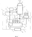
- Fig. 1 shows a device according to a first embodiment for implementing a method of the invention.
- exhaust gas generated in an engine 1 is introduced into a scrubber 2 from an air inlet 2a and comes into gas-liquid contact with scrubber cleaning water, and after toxic substances such as black carbon, soot, and oil droplets are removed by shifting to the cleaning water side, the exhaust gas is discharged from an exhaust port 2b.
- scrubber wastewater generated at this time passes from a drain port 2c into a pipe L1, and is introduced into a pipe L2 or pipe L3 via a valve 3.
- the pipe L2 communicates with a mixing tank 7 and a magnetic separation device 11 downstream of the mixing tank 7, while the pipe L3 bypasses the mixing tank 7 and magnetic separation device 11, and communicates with a pipe L6 downstream of the mixing tank 7 and magnetic separation device 11.
- wastewater is discharged without receiving treatment in the mixing tank 7 or the magnetic separation device 11, or is circulated and utilized as scrubber cleaning water.
- the pipe L1 branches on an upstream side of the valve 3 into a pipe L1a that communicates with a measurement tank 4, one portion of the wastewater is transferred through the pipe L1a to the measurement tank 4 and accumulates there, and the wastewater can be inspected using a pH measuring device 5 or a water quality measuring device 6.
- one portion of the wastewater is accumulated in the measurement tank 4 and inspected, but the pipe L1a may stand alone without the tank being provided, and wastewater flowing inside the pipe may be inspected directly.
- the piping is branched and one portion of the wastewater is removed for inspection, wastewater flowing inside the pipe L1 may be inspected directly without removing one portion of the wastewater.
- wastewater after inspection is transferred through a pipe L4 to the mixing tank 7, but the wastewater that has been inspected too, when not needed, may be returned to the pipe L1 upstream of the valve 3 and downstream of a branch point, and be able to bypass the mixing tank 7 and magnetic separation device 11 through the pipe L3.
- Water quality categories inspected by the water quality measuring device 6 include wastewater turbidity or suspended substance (SS) concentration ("suspended substance concentration" in this specification) as representative indices of suspended substances such as black carbon, soot, and oil droplets included in wastewater.
- wastewater turbidity can be measured using a method compliant with 9.3 of JIS K0101, or the like.
- wastewater suspended substance concentration can be measured using a method compliant with 14.1 of JIS K0102, or the like.
- An agitating device 15 having an agitating blade 15a rotated via a pivot 15b by a motor M is provided in the mixing tank 7, as shown in Figs. 2 to 4 . Further, wastewater is mixed by the agitating device 15 in the mixing tank 7 with an alkaline agent or acid agent added from a pH regulating device 8, magnetic powder added from a magnetic powder adding device 9, and a coagulating agent added from a coagulating agent adding device 10, whereby a bound substance (hereafter referred to as "magnetic floc") of suspended substances such as black carbon, soot, and oil droplets included in the wastewater and magnetic powder can be formed.
- the pH of wastewater is preferably regulated to 4 to 11. By so doing, alkali consumed by the coagulating agent can be supplied, because of which magnetic floc can be efficiently formed.
- the pH is preferably regulated in accordance with the pH state of wastewater measured by the pH measuring device 5.
- the magnetic powder can be added in powder form, or added in a state wherein magnetic powder is dispersed in a dispersion medium such as water.
- a material of the magnetic powder may be either a normal magnetic powder or strong magnetic powder, including, for example, a ferric oxide such as triiron tetraoxide, cobalt, chromium oxide, ferrite, and the like.
- a particle diameter of the magnetic powder is normally within a range of 0.05 ⁇ m or greater, 10 ⁇ m or less, and more preferably still, within a range of 0. 05 ⁇ m or greater, 5 ⁇ m or less.
- a coercive force of the magnetic powder is normally within a range of 10 4 /4 ⁇ A/m or greater, 4 ⁇ 10 5 /4 ⁇ A/m or less, and more preferably still, within a range of 2 ⁇ 10 5 /4 ⁇ A/m or greater, 3 ⁇ 10 5 /4 ⁇ A/m or less.
- the magnetic powder is preferably added so that a magnetic powder mass is 0.1 to 10 with respect to a suspended substance mass of 1, and more preferably still, added so that the magnetic powder mass is 0.5 to 5.
- the amount of magnetic powder added is preferably regulated in accordance with a torpidity or suspended substance concentration of wastewater measured by the water quality measuring device 6.
- a table of a relationship between measurement value and amount of magnetic powder added may be stored in advance in a control device, to be described hereafter, and the amount added determined by referring to the table.
- the coagulating agent can be added in powder form, or added in a state wherein a coagulating agent is dispersed in a dispersion medium such as water.
- a coagulating agent is dispersed in a dispersion medium such as water.
- PAC polyaluminum chloride
- ferric polysulfate, aluminum sulfate (alum) a polymer (nonionic, cationic, anionic, dipolar) , and the like
- the coagulating agent can be selected in accordance with wastewater properties.
- the coagulating agent is preferably added so that a coagulating agent mass is 0.005 to 1 with respect to a suspended substance mass of 1, and more preferably still, added so that the coagulating agent mass is 0.01 to 0.5.
- the amount of coagulating agent added is preferably regulated in accordance with a torpidity or suspended substance concentration of wastewater measured by the water quality measuring device 6.
- a table of a relationship between measurement value and amount of coagulating agent added may be stored in advance in a control device, to be described hereafter, and the amount added determined by referring to the table.
- Wastewater including magnetic floc formed by mixing with magnetic powder, a coagulating agent, and the like in the mixing tank 7 is introduced through a pipe L5 into the magnetic separation device 11 and subjected to a magnetic separation process, and sludge collected as an aggregate (lump of magnetic floc) by the magnetic separation process is stored in a sludge tank 12.
- the magnetic separation process in the magnetic separation device 11 will be described hereafter.
- a liquid portion (a clear supernatant) after magnetic separation is discharged from the pipe L6 via a valve 13 and through a pipe L7, or introduced through a pipe L8 into the scrubber 2 from a liquid inlet 2d, and reutilized as scrubber cleaning water.
- the device of this embodiment further includes a control device 14, wherein the control device 14 is connected by wiring T to each of the pH measuring device 5, the water quality measuring device 6, the pH regulating device 8, the magnetic powder adding device 9, the coagulating agent adding device 10, the magnetic separation device 11, and valves 3 and 13, and can send and receive signals, store determination data, and determine by comparing with the determination data.
- control device 14 can, for example, receive a signal relating to a measurement value from the pH measuring device 5 or the water quality measuring device 6, determine whether or not the received measurement value is within a predetermined range, send a signal relating to the amount of alkaline agent or acid agent to be added to the pH regulating device 8, a signal relating to the amount of magnetic powder to be added to the magnetic powder adding device 9, and a signal relating to the amount of coagulating agent to be added to the coagulating agent adding device 10, send a signal relating to the necessity or otherwise of operating to the magnetic separation device 11, and send a signal relating to pipe connection by the valves 3 and 13.
- valve 3 may be of a configuration such that the valve 3 can arbitrarily change the ratios of the amounts of wastewater passing into the pipe 2 and the pipe L3, and can arbitrarily select the ratios of the amount of wastewater to be treated and the amount of wastewater not to be treated.
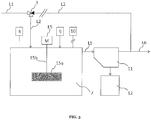
- Fig. 2 shows a first operation example of the heretofore described device.
- wastewater from the pipe L1 flows into the pipe L3 owing to a connection of the valve 3, which is formed of a three-way valve, bypasses the mixing tank 7 and magnetic separation device 11, and is transferred to the pipe L6 downstream of the mixing tank 7 and magnetic separation device 11.
- This kind of operation example is appropriate when the amount of suspended substances in the wastewater is within a range such that a suspended substance removal process is unnecessary (hereafter referred to as "range A”), and there is no need to remove the suspended substances in the wastewater.
- An upper limit value of the range A (hereafter referred to as a "boundary value AB") differs in accordance with a scrubber device configuration, application, discharge regulation standard, and the like, but is preferably set, for example, within a range of 25 to 100NTU when taking wastewater torpidity as an index, or within a range of 10 to 50mg/L when taking wastewater suspended substance concentration as an index.
- a boundary value AB there is no addition of magnetic powder from the magnetic powder adding device 9, no addition of the coagulating agent from the coagulating agent adding device 10, or the like, and the agitating device 15 and the magnetic separation device 11 do not operate either.
- Addition of an alkaline agent or an acid agent from the pH regulating device 8 is arbitrary.
- Fig. 3 shows a second operation example of the heretofore described device.
- wastewater from the pipe L1 flows into the pipe L2 owing to a connection of the valve 3, which is formed of a three-way valve, and is transferred to the mixing tank 7.
- the mixing tank 7 magnetic powder is added from the magnetic powder adding device 9 to wastewater that is stored in the tank for a certain time, and the wastewater is agitated by the agitating device 15, thereby causing magnetic floc to be formed.
- Addition of an alkaline agent or an acid agent from the pH regulating device 8 is arbitrary.
- range B This kind of operation example is appropriate in a range wherein wastewater suspended substances can be treated with magnetic powder alone to form magnetic floc (hereafter referred to as "range B"), and there is no need to go as far as adding a coagulating agent.
- An upper limit value of the range B (hereafter referred to as a "boundary value BC”) differs in accordance with a scrubber device configuration, an application, a discharge regulation standard, and the like, but is preferably, for example, a value within a range of 50 to 150NTU, and 25NTU or more greater than the boundary value AB, when taking wastewater torpidity as an index, or a value within a range of 20 to 100mg/L, and 10mg/L or more greater than the boundary value AB, when taking wastewater suspended substance concentration as an index.
- the wastewater suspended substances can be treated with magnetic powder alone to form magnetic floc. Therefore, no addition of coagulating agent from the coagulating agent adding device 10 is carried out.
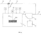
- Fig. 4 shows a third operation example of the heretofore described device.
- wastewater from the pipe L1 flows into the pipe L2 owing to a connection of the valve 3, which is formed of a three-way valve, and is transferred to the mixing tank 7.
- the mixing tank 7 together with magnetic powder being added from the magnetic powder adding device 9, a coagulating agent is added from the coagulating agent adding device 10 to wastewater that is stored in the tank for a certain time, and the wastewater is agitated by the agitating device 15, thereby causing magnetic floc to be formed.
- Addition of an alkaline agent or an acid agent from the pH regulating device 8 is arbitrary.
- range C This kind of operation example is appropriate in a range wherein wastewater suspended substances cannot be treated with magnetic powder alone, and it is necessary to use a coagulating agent concurrently (hereafter referred to as "range C").
- the range C is preferably a range exceeding the boundary value BC, that is, a range exceeding 50 to 150NTU when taking wastewater torpidity as an index, or a range exceeding 20 to 100mg/L when taking wastewater suspended substance concentration as an index.
- an agitation operation is desirably regulated so as to agitate strongly at first in order to form a minute micro-floc, and next to agitate weakly in order to cause a larger floc to grow, and these operations may be carried out separately by dividing the mixing tank 7 into two or more receptacles.
- the first to third operation examples can be controlled by, for example, the water quality measuring device 6 and the control device 14.
- Fig. 5 shows a flowchart representing one example of the control.
- wastewater is inspected by the water quality measuring device 6, a measurement value thereof is compared with the determination data stored in advance in the control device 14, and it is determined whether the measurement value is within the range A wherein a suspended substance removal process is unnecessary, in other words, whether or not the measurement value is equal to or lower than the boundary value AB (step S1).
- the valve 3 is connected to the pipe L3 (step S2), and the wastewater is discharged or recirculated (step S3), according to the first operation example.
- step S4 when the measurement value exceeds the boundary value AB, the valve 3 is connected to the pipe L2 (step S4), the measurement value from the water quality measuring device 6 is compared with the determination data stored in advance in the control device 14, and it is determined whether the measurement value is within the range B wherein processing can be carried out by adding only magnetic powder, in other words, whether or not the measurement value is equal to or lower than the boundary value BC (step S5).
- step S6 When the measurement value is equal to or lower than the boundary value BC, magnetic floc is caused to form by adding magnetic powder from the magnetic powder adding device 9 (step S6), the wastewater is magnetically separated into an aggregate (lump of magnetic floc) and a liquid portion (clear supernatant) by the magnetic separation device 11 (step S7), and the wastewater after treatment is discharged or recirculated (step S8), according to the second operation example.
- step S9 when the measurement value exceeds the boundary value BC, it is determined that the measurement value is within the range C wherein magnetic powder and a coagulating agent need to be used concurrently (step S9), and together with magnetic powder being added from the magnetic powder adding device 9 (step S10), a coagulating agent is added from the coagulating agent adding device 10, whereby magnetic floc is caused to form (step S11), the wastewater is magnetically separated into an aggregate (lump of magnetic floc) and a liquid portion (clear supernatant) by the magnetic separation device 11 (step S12), and the wastewater after treatment is discharged or recirculated (step S13), according to the third operation example.
- range A, range B, and range C need to be set as ranges that do not overlap each other.
- setting is such that range A is equal to or lower than the boundary value AB, range B exceeds the boundary value AB and is equal to or lower than the boundary value BC, range C exceeds the boundary value BC, and the like.
- Fig. 6 shows an example of a magnetic separation device included in the device according to the first embodiment.
- a channel 21 that communicates with the pipe L5 extending from the mixing tank 7 is provided in this magnetic separation device 20, and the channel 21 has a predetermined capacity, because of which, when wastewater that has finished treatment in the mixing tank 7 passes through the channel 21, the wastewater passes through while being retained for a predetermined time.
- a rotating disk 22 is disposed above the channel 21 so that approximately a lower half portion of the rotating disk 22 is immersed in the wastewater flowing through the channel 21, and the rotating disk 22 is rotated by unshown drive means.
- a direction of rotation in a circumferential direction of the rotating disk 22 is a forward direction with respect to the flow in a portion immersed in the wastewater.
- a multiple of blades of the rotating disk 22 are coaxially arrayed in parallel at predetermined intervals in an unshown depth direction, and are disposed over practically the whole of a width direction of the channel 21, in a state such as to leave a slight gap.
- a magnet is disposed over the whole of a surface of the rotating disk 22, or within a range that can practically cover the depth of water flowing through the channel 21, and magnetic floc formed in the wastewater adheres to the surface of the rotating disk 22 owing to magnetic attraction force of the magnet.
- a scraper 23 is disposed along a surface on either side of the rotating disk 22 in a portion of the rotating disk 22 exposed on a surface of the wastewater, and sludge wherein magnetic floc forms a lump is scraped off and stored in the sludge tank 12.
- Fig. 7 shows another example of a magnetic separation device included in the device according to the first embodiment.
- a rotating drum 32 on a cylindrical side surface of which a magnet is disposed, is used in this magnetic separation device 30 instead of the rotating disk 22 shown in Fig. 6 .
- the rotating drum 32 is disposed so that a lower half portion is immersed in the wastewater, and a scraper 33 is disposed along a side surface of the rotating drum 32 in a portion of the rotating drum 32 exposed on the surface of the wastewater.
- Magnetic floc formed in the wastewater adheres to the side surface of the rotating drum 32 owing to the magnet disposed on the rotating drum 32, and sludge wherein magnetic floc forms a lump is scraped off by the scraper 33 and stored in the sludge tank 12.
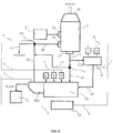
- Fig. 8 shows a device according to a second embodiment for implementing the method of the invention.
- the device according to this embodiment differs from the device according to the first embodiment in that a mixing tank 7a and a magnetic separation device 11a are configured integrally.
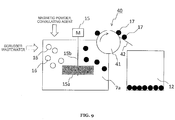
- Fig. 9 shows an example of a magnetic separation device included in the device according to the second embodiment.
- This magnetic separation device 40 shares a basic configuration with the magnetic separation device 30 illustrated in Fig. 7 , but is installed directly in the mixing tank 7a rather than being a channel extending from the mixing tank.
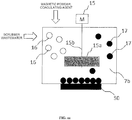
- a lower half portion of a rotating drum 41 of the magnetic separation device 40 is disposed so as to be immersed in wastewater in the mixing tank 7a, the magnetic floc 17 formed by adding magnetic powder, or magnetic powder and a coagulating agent, to a suspended substance 16 such as black carbon, soot, or oil and mixing in the mixing tank 7a is caused to adhere to a side surface of the rotating drum 41 by a magnet disposed on the rotating drum 41, and sludge wherein magnetic floc forms a lump is scraped off by the scraper 42 and stored in the sludge tank 12.
- Fig. 10 shows a device according to a third embodiment for implementing the method of the invention.
- the device according to this embodiment differs from the device according to the first embodiment in that a mixing tank 7b and a magnetic separation device 11b are configured integrally, and furthermore, the mixing tank 7b also performs a function of a sludge tank. That is, in this embodiment, sludge accumulates in a bottom portion of the mixing tank 7b, and the sludge is regularly discharged from an unshown outlet.
- Fig. 11 shows an example of a magnetic separation device included in the device according to the third embodiment.
- This magnetic separation device 50 is formed of an electromagnet, and is disposed partitioning a bottom surface of the mixing tank 7b on an exterior thereof.
- the magnetic floc 17 formed by adding magnetic powder, or magnetic powder and a coagulating agent, to the suspended substance 16 such as black carbon, soot, or oil and mixing in the mixing tank 7b is attracted by the electromagnet, and accumulated on an interior bottom surface of the mixing tank 7b.
- sludge wherein the magnetic floc forms a lump can be discharged from the mixing tank 7b via an unshown sludge removal route by causing clean water to flow in place of the wastewater while carrying out agitation in the agitation device 15, with the electromagnet in an off state.
- Fig. 12 shows a device according to a fourth embodiment for implementing the method of the invention.
- the device according to this embodiment differs from the device according to the first embodiment in that a mixing pipe 7c including an in-line mixer is provided in place of the mixing tank, the mixing pipe 7c and a magnetic separation device 11c are configured integrally, and furthermore, these structures also perform a function of a sludge tank.
- Fig. 13 shows an example of a magnetic separation device included in the device according to the fourth embodiment.
- This magnetic separation device 60 is formed of an electromagnet, and is disposed partitioning a side surface of the mixing pipe 7c including the in-line mixer, on an exterior thereof.
- the magnetic floc 17 formed by adding magnetic powder, or magnetic powder and a coagulating agent, to the suspended substance 16 such as black carbon, soot, or oil and mixing with the unshown in-line mixer in the mixing pipe 7c is attracted by the electromagnet, and accumulated on an interior side surface of the mixing pipe 7c.
- sludge wherein the magnetic floc forms a lump can be discharged from the mixing pipe 7c via an unshown sludge removal route by causing clean water to flow in place of the wastewater, with the electromagnet in an off state.
- Fig. 14 shows another example of a magnetic separation device included in the device according to the fourth embodiment.
- This magnetic separation device 70 is configured of a sludge storage pipe 71 branching off the mixing pipe 7c including the in-line mixer, a pipeline induction guide 72 disposed in an intersection portion on an interior side surface of a portion that branches off from the mixing pipe 7c to the sludge storage pipe 71, a magnetism generating drum 73 disposed in a position on a pipe exterior opposing the pipeline induction guide 72 and rotating with a predetermined axis of rotation, and an electromagnet 74 disposed partitioning a side surface of the sludge storage pipe 71, on an exterior thereof.
- the magnetic floc 17 formed by adding magnetic powder, or magnetic powder and a coagulating agent, to the suspended substance 16 such as black carbon, soot, or oil and mixing with the unshown in-line mixer in the mixing pipe 7c is attracted to the sludge storage pipe 71 side by actions of the pipeline induction guide 72 and the magnetism generating drum 73, transferred to the sludge storage pipe 71 together with a flow of wastewater, attracted to the electromagnet 74 disposed on the exterior side surface of the sludge storage pipe 71, and accumulated on an interior side surface of the sludge storage pipe 71.
- sludge wherein the magnetic floc forms a lump can be discharged from the sludge storage pipe 71 and the mixing pipe 7c via an unshown sludge removal route by causing clean water to flow in place of the wastewater, with the electromagnet in an off state.
- Exhaust gas of a diesel engine is treated using a scrubber, whereby scrubber wastewater of 240NTU (formazin) torpidity and 80mg/L suspended substance concentration is prepared, and polyaluminum chloride (PAC) is added as a coagulating agent so that a coagulating agent mass with respect to suspended substance mass is 100:5.
- scrubber wastewater of 240NTU (formazin) torpidity and 80mg/L suspended substance concentration
- PAC polyaluminum chloride
- High-speed agitation at 150rpm is carried out for 20 seconds using a bell-jar stator, after which low-speed agitation at 40rpm is carried out for 20 minutes, and the wastewater is moved to a measuring cylinder of 500mL capacity. A height of an interface between a transparent portion and a suspended portion is measured over time as a treatment speed index.
- sampling is carried out in a position 2cm from the water surface after coagulation-sedimentation, and torpidity is measured using a portable torpidimeter 2100Q (made by HACH) . Furthermore, that which remains after a supernatant is removed by decantation after coagulation-sedimentation is taken to be sludge, and a moisture content is measured using an infrared moisture meter.
- test example 2 has been carried out in the same way as test example 1.
- Triiron tetraoxide is added as magnetic powder to the scrubber wastewater so that a magnetic powder mass is 1:1 with respect to a suspended substance mass.
- High-speed agitation at 150rpm is carried out for 20 seconds using a bell-jar stator, after which the wastewater is moved to a measuring cylinder of 500mL capacity, and the measuring cylinder is placed on a neodymium magnet.
- the height of an interface between a transparent portion and a suspended portion is measured over time.
- sampling is carried out in a position 2cm from the water surface after coagulation-sedimentation, and torpidity is measured. Furthermore, the sludge moisture content is measured.
- Triiron tetraoxide is added as magnetic powder to the scrubber wastewater so that a magnetic powder mass is 1:1 with respect to a suspended substance mass, and furthermore, ferric polysulfate is added as a coagulating agent so that a coagulating agent mass is 100:5 with respect to the suspended substance mass.
- High-speed agitation at 150rpm is carried out for 20 seconds using a bell-jar stator, after which the wastewater is moved to a measuring cylinder of 500mL capacity, and the measuring cylinder is placed on a neodymium magnet.
- the height of an interface between a transparent portion and a suspended portion is measured over time.
- sampling is carried out in a position 2cm from the water surface after coagulation-sedimentation, and torpidity is measured. Furthermore, the sludge moisture content is measured.
- Fig. 15 shows results of a height of an interface between a transparent portion and a suspended portion. As shown in Fig. 15 , hardly any decrease in interface height occurs within the testing time in comparison example 1, or in test examples 1 and 2 in which a coagulating agent is added. As opposed to this, it is seen that in test example 3, in which metallic powder is added, and in test example 4, in which metallic powder and a coagulating agent are added, the interface reaches the vicinity of the bottom of the measuring cylinder in around four minutes, and coagulation-sedimentation is swiftly completed by magnetic separation.
- Fig. 16 shows results of torpidity in a position 2cm from the water surface. As shown in Fig. 16 , hardly any decrease in torpidity in the vicinity of the water surface occurs in comparison example 1. As opposed to this, torpidity in the vicinity of the water surface decreases in test examples 1 and 2, in which a coagulating agent is added, and an improvement in water quality can be confirmed. Meanwhile, torpidity in the vicinity of the water surface also decreases in test example 3, in which metallic powder is added, and in test example 4, in which metallic powder and a coagulating agent are added, and an improvement in water quality can be confirmed.
- the torpidity after treatment is in the region of 60NTU in test example 3, in which metallic powder is added, and although the torpidity is a little too high for discharging, it is of a level such that there is no problem in reutilizing in the scrubber. Also, the torpidity decreases to 12NTU in test example 4, in which metallic powder and a coagulating agent are added, which is a level such that discharging can be carried out.
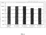
- Fig. 17 shows results of collected sludge moisture content.
- collecting sludge is difficult, because of which the moisture content of the wastewater itself is measured for the sake of convenience, as a result of which the moisture content is taken to be 100%.
- the sludge moisture content is high at 99.5% both when using polyaluminum chloride (PAC) as a coagulating agent (test example 1) and when using ferric polysulfate (test example 2).
- PAC polyaluminum chloride
- the moisture content is 89% both in the case of magnetic powder alone in test example 3, and in the case of using magnetic powder and ferric polysulfate concurrently in test example 4.
- sludge derived from magnetic separation has a volume in the region of one-two hundredth compared with sludge collected using a coagulating agent alone.
- sludge collected using a coagulating agent alone has a low density, because of which the sludge is extremely weak against the power of the water flow and the like, and the sludge is stirred up when decanting, or the like.
- sludge derived from magnetic separation is in a state attracted to a magnet across a bottom of a receptacle, does not become detached even when the receptacle is inverted, and is extremely strong against the power of the water flow and the like.
Landscapes
- Chemical & Material Sciences (AREA)
- Chemical Kinetics & Catalysis (AREA)
- Life Sciences & Earth Sciences (AREA)
- Hydrology & Water Resources (AREA)
- Engineering & Computer Science (AREA)
- Environmental & Geological Engineering (AREA)
- Water Supply & Treatment (AREA)
- Organic Chemistry (AREA)
- Analytical Chemistry (AREA)
- Separation Of Suspended Particles By Flocculating Agents (AREA)
Abstract
Description
- The present invention relates to a method of treating scrubber wastewater generated when treating combustion exhaust gas with a scrubber, and to a scrubber wastewater treatment device.
- Combustion exhaust gas generated in a diesel engine of a ship, a furnace, or the like, includes black carbon, soot, oil droplets, and the like, because of which the exhaust gas is passed through a dirt collecting device (scrubber), cleaning water is brought into contact with the gas by spraying, and the toxic substances are removed by being shifted to the cleaning water side. Meanwhile, scrubber wastewater generated when treating with this kind of dirt collecting device (scrubber) includes collected toxic substances such as black carbon, soot, and oil droplets, and these too need to be removed so as not to be released into the environment. To date, methods such as centrifugal separation (refer to following PTL 1), filtration treatment (refer to following PTL 2 (paragraph 0019)), coagulation-sedimentation (refer to following PTL 3 (paragraph 0004)), and the like, have been employed in the removal of toxic substances from scrubber wastewater.
-
- PTL 1:
JP-A-2004-81933 - PTL 2:
JP-A-11-165180 - PTL 3:
JP-A-2001-129596 - However, there is a problem with centrifugal separation in that a device consumes a large amount of power, and power generating equipment is needed for this, meaning that large-scale facilities are needed. Also, there is a problem with safety in a rolling ship or the like. In the case of filtration treatment, maintenance involving filter material replacement or cleaning due to clogging is troublesome. There are problems with coagulation-sedimentation in that coagulated floc needs to be left standing for a long time in order to cause the floc to precipitate, meaning that efficiency is poor, and a precipitate that has once been formed is liable to be stirred up in a rolling ship or the like, meaning that stable and efficient solid-liquid separation is difficult.
- Therefore, an object of the invention is to provide a scrubber wastewater treatment method and scrubber wastewater treatment device such that solid-liquid separation of a once formed floc is easy, with no need for large-scale facilities or troublesome maintenance.
- In order to achieve the heretofore described object, a scrubber wastewater treatment method of the invention is characterized in that a magnetic powder is added to scrubber wastewater generated when treating combustion exhaust gas in a scrubber, a bound substance of a suspended substance included in scrubber wastewater and the magnetic powder is formed, and the bound substance is magnetically separated, thereby cleaning the wastewater.
- According to the scrubber wastewater treatment method of the invention, even in the case of a suspended substance included in scrubber wastewater such as black carbon, soot, or oil, which has a low specific gravity and precipitates with difficulty, the suspended substance can be efficiently removed, and the wastewater cleaned, by magnetically separating the suspended substance together with a magnetic powder.
- The scrubber wastewater treatment method of the invention is preferably such that a coagulating agent is further added together with the magnetic powder to the scrubber wastewater, a bound substance of a suspended substance included in the scrubber wastewater and the magnetic powder is formed, and the bound substance is magnetically separated. By so doing, the efficiency of a bound substance of a suspended substance included in the scrubber wastewater and a magnetic powder being formed increases, because of which wastewater can be cleaned more efficiently.
- Also, preferably, a range A wherein no suspended substance removal process is necessary, a range B wherein treatment can be carried out by an addition of a magnetic powder alone, and a range C wherein a magnetic powder and a coagulating agent need to be used concurrently, are set in advance with regard to a torpidity or suspended substance concentration of the scrubber wastewater, the torpidity or suspended substance concentration is measured, the scrubber wastewater is discharged as it is, or circulated and used, when the torpidity or suspended substance concentration is in range A, treatment is carried out by adding magnetic powder only to the scrubber wastewater when the torpidity or suspended substance concentration is in range B, and treatment is carried out by adding magnetic powder and a coagulating agent to the scrubber wastewater when the torpidity or suspended substance concentration is in range C. By so doing, magnetic powder or a coagulating agent is added in accordance with scrubber wastewater torpidity or suspended substance concentration, excessive use of magnetic powder or a coagulating agent is restricted, and running costs can be restricted.
- Also, an amount of the magnetic powder added and/or an amount of the coagulating agent added when the range of the torpidity or suspended substance concentration is B or C is preferably an amount in accordance with the torpidity or suspended substance concentration. By so doing, excessive use of magnetic powder or a coagulating agent is effectively restricted, and running costs can be further restricted.
- Also, a boundary value of the range A and range B is preferably set in a range of 25 to 100NTU torpidity.
- Also, a boundary value of the range A and range B is preferably set in a range of 10 to 50mg/L suspended substance concentration.
- Also, a boundary value of the range B and the range C is preferably set in a range of 50 to 150NTU torpidity, and is a value 25NTU or more greater than a boundary value of the range A and the range B.
- Also, a boundary value of the range B and the range C is preferably set in a range of 20 to 100mg/L suspended substance concentration, and is a value 10mg/L or more greater than a boundary value of the range A and the range B.
- Meanwhile, a scrubber wastewater treatment device of the invention is characterized by including a magnetic powder adding device that adds a magnetic powder to scrubber wastewater generated when treating combustion exhaust gas in a scrubber, and a magnetic separation device that magnetically separates a bound substance of a suspended substance included in the scrubber wastewater and the magnetic powder.
- According to the scrubber wastewater treatment device of the invention, even in the case of a suspended substance included in scrubber wastewater such as black carbon, soot, or oil, which has a low specific gravity and precipitates with difficulty, the suspended substance can be efficiently removed, and the wastewater cleaned, by magnetically separating the suspended substance together with a magnetic powder.
- The scrubber wastewater treatment device of the invention preferably further includes a coagulating agent adding device that adds a coagulating agent to the scrubber wastewater. By so doing, the efficiency of a bound substance of a suspended substance included in scrubber wastewater and a magnetic powder being formed by using a coagulating agent increases, because of which wastewater can be cleaned more efficiently.
- Also, the scrubber wastewater treatment device of the invention preferably further includes a measuring device that measures a torpidity or suspended substance concentration of the scrubber wastewater, and a control device that controls an amount of magnetic powder added from the magnetic powder adding device in accordance with a measurement value from the measuring device. By so doing, magnetic powder is not used more than necessary, because of which running costs can be restricted.
- Also, the scrubber wastewater treatment device of the invention preferably further includes a measuring device that measures a torpidity or suspended substance concentration of the scrubber wastewater, and a control device that controls an amount of magnetic powder added from the magnetic powder adding device and an amount of coagulating agent added from the coagulating agent adding device in accordance with a measurement value from the measuring device. By so doing, magnetic powder and coagulating agent are not used more than necessary, because of which running costs can be restricted.
- Also, preferably, a range A wherein no suspended substance removal process is necessary, a range B wherein treatment can be carried out by an addition of a magnetic powder alone, and a range C wherein a magnetic powder and a coagulating agent need to be used concurrently, are input in advance into the control device with regard to a torpidity or suspended substance concentration of the scrubber wastewater, the torpidity or suspended substance concentration is measured by the measuring device and compared with the ranges input in advance into the control device, the scrubber wastewater is discharged as it is, or circulated and used, when the torpidity or suspended substance concentration is in range A, treatment is carried out by adding magnetic powder only to the scrubber wastewater when the torpidity or suspended substance concentration is in range B, and treatment is carried out by adding magnetic powder and a coagulating agent to the scrubber wastewater when the torpidity or suspended substance concentration is in range C.
- According to the invention, even in the case of a suspended substance included in scrubber wastewater such as black carbon, soot, or oil, which has a low specific gravity and precipitates with difficulty, the suspended substance can be efficiently removed, and the wastewater cleaned, by magnetically separating the suspended substance together with a magnetic powder. Also, by using a coagulating agent concurrently, the efficiency of a bound substance of a suspended substance included in scrubber wastewater and a magnetic powder being formed increases, because of which wastewater can be cleaned more efficiently.
-
- [
Fig. 1] Fig. 1 is a schematic configuration diagram of a device according to a first embodiment for implementing a method of the invention. - [
Fig. 2] Fig. 2 is an illustration of a first operation example of the aforementioned device. - [
Fig. 3] Fig. 3 is an illustration of a second operation example of the aforementioned device. - [
Fig. 4] Fig. 4 is an illustration of a third operation example of the aforementioned device. - [
Fig. 5] Fig. 5 is a flowchart representing an example of the first to third operation examples being reciprocally controlled. - [
Fig. 6] Fig. 6 is a schematic configuration diagram showing an example of a magnetic separation device included in the device according to the first embodiment. - [
Fig. 7] Fig. 7 is a schematic configuration diagram showing another example of a magnetic separation device included in the device according to the first embodiment. - [
Fig. 8] Fig. 8 is a schematic configuration diagram of a device according to a second embodiment for implementing the method of the invention. - [
Fig. 9] Fig. 9 is a schematic configuration diagram showing an example of a magnetic separation device included in the device according to the second embodiment. - [
Fig. 10] Fig. 10 is a schematic configuration diagram of a device according to a third embodiment for implementing the method of the invention. - [
Fig. 11] Fig. 11 is a schematic configuration diagram showing an example of a magnetic separation device included in the device according to the third embodiment. - [
Fig. 12] Fig. 12 is a schematic configuration diagram of a device according to a fourth embodiment for implementing the method of the invention. - [
Fig. 13] Fig. 13 is a schematic configuration diagram showing an example of a magnetic separation device included in the device according to the fourth embodiment. - [
Fig. 14] Fig. 14 is a schematic configuration diagram showing another example of a magnetic separation device included in the device according to the fourth embodiment. - [
Fig. 15] Fig. 15 is a graph showing results of a height of an interface between a transparent portion and a suspended portion being measured over time in a scrubber wastewater coagulation-sedimentation test. - [
Fig. 16] Fig. 16 is a graph showing results of sampling being carried out in a position 2cm from a water surface, and torpidity being measured, after coagulation-sedimentation in a scrubber wastewater coagulation-sedimentation test. - [
Fig. 17] Fig. 17 is a graph showing results of that which remains after a supernatant is removed by decantation after coagulation-sedimentation being taken to be sludge, and a moisture content being measured using an infrared moisture meter, in a scrubber wastewater coagulation-sedimentation test. - Hereafter, while referring to the drawings, a description will be given of embodiments of the invention.
-
Fig. 1 shows a device according to a first embodiment for implementing a method of the invention. In this embodiment, exhaust gas generated in anengine 1 is introduced into ascrubber 2 from anair inlet 2a and comes into gas-liquid contact with scrubber cleaning water, and after toxic substances such as black carbon, soot, and oil droplets are removed by shifting to the cleaning water side, the exhaust gas is discharged from anexhaust port 2b. Also, scrubber wastewater generated at this time passes from adrain port 2c into a pipe L1, and is introduced into a pipe L2 or pipe L3 via avalve 3. Further, the pipe L2 communicates with amixing tank 7 and amagnetic separation device 11 downstream of themixing tank 7, while the pipe L3 bypasses themixing tank 7 andmagnetic separation device 11, and communicates with a pipe L6 downstream of themixing tank 7 andmagnetic separation device 11. Owing to this bypass route, wastewater is discharged without receiving treatment in themixing tank 7 or themagnetic separation device 11, or is circulated and utilized as scrubber cleaning water. Also, the pipe L1 branches on an upstream side of thevalve 3 into a pipe L1a that communicates with ameasurement tank 4, one portion of the wastewater is transferred through the pipe L1a to themeasurement tank 4 and accumulates there, and the wastewater can be inspected using apH measuring device 5 or a waterquality measuring device 6. In this embodiment, one portion of the wastewater is accumulated in themeasurement tank 4 and inspected, but the pipe L1a may stand alone without the tank being provided, and wastewater flowing inside the pipe may be inspected directly. Also, although the piping is branched and one portion of the wastewater is removed for inspection, wastewater flowing inside the pipe L1 may be inspected directly without removing one portion of the wastewater. Also, wastewater after inspection is transferred through a pipe L4 to themixing tank 7, but the wastewater that has been inspected too, when not needed, may be returned to the pipe L1 upstream of thevalve 3 and downstream of a branch point, and be able to bypass themixing tank 7 andmagnetic separation device 11 through the pipe L3. - Water quality categories inspected by the water
quality measuring device 6 include wastewater turbidity or suspended substance (SS) concentration ("suspended substance concentration" in this specification) as representative indices of suspended substances such as black carbon, soot, and oil droplets included in wastewater. For example, wastewater turbidity can be measured using a method compliant with 9.3 of JIS K0101, or the like. Also, wastewater suspended substance concentration can be measured using a method compliant with 14.1 of JIS K0102, or the like. - An agitating
device 15 having an agitatingblade 15a rotated via apivot 15b by a motor M is provided in themixing tank 7, as shown inFigs. 2 to 4 . Further, wastewater is mixed by the agitatingdevice 15 in themixing tank 7 with an alkaline agent or acid agent added from apH regulating device 8, magnetic powder added from a magneticpowder adding device 9, and a coagulating agent added from a coagulatingagent adding device 10, whereby a bound substance (hereafter referred to as "magnetic floc") of suspended substances such as black carbon, soot, and oil droplets included in the wastewater and magnetic powder can be formed. The pH of wastewater is preferably regulated to 4 to 11. By so doing, alkali consumed by the coagulating agent can be supplied, because of which magnetic floc can be efficiently formed. The pH is preferably regulated in accordance with the pH state of wastewater measured by thepH measuring device 5. - The magnetic powder can be added in powder form, or added in a state wherein magnetic powder is dispersed in a dispersion medium such as water. A material of the magnetic powder may be either a normal magnetic powder or strong magnetic powder, including, for example, a ferric oxide such as triiron tetraoxide, cobalt, chromium oxide, ferrite, and the like. Preferably, a particle diameter of the magnetic powder is normally within a range of 0.05µm or greater, 10µm or less, and more preferably still, within a range of 0. 05µm or greater, 5µm or less. Also, preferably, a coercive force of the magnetic powder is normally within a range of 104/4πA/m or greater, 4 × 10⁵/4πA/m or less, and more preferably still, within a range of 2 × 10⁵/4πA/m or greater, 3 × 10⁵/4πA/m or less. With regard to an amount of magnetic powder added, the magnetic powder is preferably added so that a magnetic powder mass is 0.1 to 10 with respect to a suspended substance mass of 1, and more preferably still, added so that the magnetic powder mass is 0.5 to 5. When the amount added is less than this range, there is a tendency for the magnetic floc forming efficiency to worsen, and when the amount added exceeds the range, the magnetic powder is unnecessarily used excessively, and a cost thereof increases, meaning that both cases are undesirable. Also, the amount of magnetic powder added is preferably regulated in accordance with a torpidity or suspended substance concentration of wastewater measured by the water
quality measuring device 6. In this case, for example, a table of a relationship between measurement value and amount of magnetic powder added may be stored in advance in a control device, to be described hereafter, and the amount added determined by referring to the table. - The coagulating agent can be added in powder form, or added in a state wherein a coagulating agent is dispersed in a dispersion medium such as water. For example, polyaluminum chloride (PAC), ferric polysulfate, aluminum sulfate (alum), a polymer (nonionic, cationic, anionic, dipolar) , and the like, are included as coagulating agent components, and the coagulating agent can be selected in accordance with wastewater properties. With regard to an amount of coagulating agent added, the coagulating agent is preferably added so that a coagulating agent mass is 0.005 to 1 with respect to a suspended substance mass of 1, and more preferably still, added so that the coagulating agent mass is 0.01 to 0.5. When the amount added is less than this range, there is a tendency for the efficiency of aiding magnetic floc formation to worsen, and when the amount added exceeds the range, the coagulating agent is unnecessarily used excessively, and a cost thereof increases, meaning that both cases are undesirable. Also, the amount of coagulating agent added is preferably regulated in accordance with a torpidity or suspended substance concentration of wastewater measured by the water
quality measuring device 6. In this case, for example, a table of a relationship between measurement value and amount of coagulating agent added may be stored in advance in a control device, to be described hereafter, and the amount added determined by referring to the table. - Wastewater including magnetic floc formed by mixing with magnetic powder, a coagulating agent, and the like in the
mixing tank 7 is introduced through a pipe L5 into themagnetic separation device 11 and subjected to a magnetic separation process, and sludge collected as an aggregate (lump of magnetic floc) by the magnetic separation process is stored in asludge tank 12. The magnetic separation process in themagnetic separation device 11 will be described hereafter. - A liquid portion (a clear supernatant) after magnetic separation is discharged from the pipe L6 via a
valve 13 and through a pipe L7, or introduced through a pipe L8 into thescrubber 2 from aliquid inlet 2d, and reutilized as scrubber cleaning water. - The device of this embodiment further includes a
control device 14, wherein thecontrol device 14 is connected by wiring T to each of thepH measuring device 5, the waterquality measuring device 6, thepH regulating device 8, the magneticpowder adding device 9, the coagulatingagent adding device 10, themagnetic separation device 11, andvalves control device 14 can, for example, receive a signal relating to a measurement value from thepH measuring device 5 or the waterquality measuring device 6, determine whether or not the received measurement value is within a predetermined range, send a signal relating to the amount of alkaline agent or acid agent to be added to thepH regulating device 8, a signal relating to the amount of magnetic powder to be added to the magneticpowder adding device 9, and a signal relating to the amount of coagulating agent to be added to the coagulatingagent adding device 10, send a signal relating to the necessity or otherwise of operating to themagnetic separation device 11, and send a signal relating to pipe connection by thevalves - The foregoing description has as a precondition an aspect wherein all wastewater is treated, but a configuration may be such that wastewater is caused to diverge using a pipe, valve, or the like, one portion is treated, and the treated water and untreated wastewater are mixed and discharged, or reutilized as scrubber cleaning water. In this case, the
valve 3 may be of a configuration such that thevalve 3 can arbitrarily change the ratios of the amounts of wastewater passing into thepipe 2 and the pipe L3, and can arbitrarily select the ratios of the amount of wastewater to be treated and the amount of wastewater not to be treated. -
Fig. 2 shows a first operation example of the heretofore described device. In this operation example, wastewater from the pipe L1 flows into the pipe L3 owing to a connection of thevalve 3, which is formed of a three-way valve, bypasses themixing tank 7 andmagnetic separation device 11, and is transferred to the pipe L6 downstream of themixing tank 7 andmagnetic separation device 11. This kind of operation example is appropriate when the amount of suspended substances in the wastewater is within a range such that a suspended substance removal process is unnecessary (hereafter referred to as "range A"), and there is no need to remove the suspended substances in the wastewater. An upper limit value of the range A (hereafter referred to as a "boundary value AB") differs in accordance with a scrubber device configuration, application, discharge regulation standard, and the like, but is preferably set, for example, within a range of 25 to 100NTU when taking wastewater torpidity as an index, or within a range of 10 to 50mg/L when taking wastewater suspended substance concentration as an index. In this case, there is no addition of magnetic powder from the magneticpowder adding device 9, no addition of the coagulating agent from the coagulatingagent adding device 10, or the like, and the agitatingdevice 15 and themagnetic separation device 11 do not operate either. Addition of an alkaline agent or an acid agent from thepH regulating device 8 is arbitrary. -
Fig. 3 shows a second operation example of the heretofore described device. In this operation example, wastewater from the pipe L1 flows into the pipe L2 owing to a connection of thevalve 3, which is formed of a three-way valve, and is transferred to themixing tank 7. In themixing tank 7, magnetic powder is added from the magneticpowder adding device 9 to wastewater that is stored in the tank for a certain time, and the wastewater is agitated by the agitatingdevice 15, thereby causing magnetic floc to be formed. Addition of an alkaline agent or an acid agent from thepH regulating device 8 is arbitrary. This kind of operation example is appropriate in a range wherein wastewater suspended substances can be treated with magnetic powder alone to form magnetic floc (hereafter referred to as "range B"), and there is no need to go as far as adding a coagulating agent. An upper limit value of the range B (hereafter referred to as a "boundary value BC") differs in accordance with a scrubber device configuration, an application, a discharge regulation standard, and the like, but is preferably, for example, a value within a range of 50 to 150NTU, and 25NTU or more greater than the boundary value AB, when taking wastewater torpidity as an index, or a value within a range of 20 to 100mg/L, and 10mg/L or more greater than the boundary value AB, when taking wastewater suspended substance concentration as an index. Provided that wastewater suspended substances are within the range B, the wastewater suspended substances can be treated with magnetic powder alone to form magnetic floc. Therefore, no addition of coagulating agent from the coagulatingagent adding device 10 is carried out. -
Fig. 4 shows a third operation example of the heretofore described device. In this operation example, wastewater from the pipe L1 flows into the pipe L2 owing to a connection of thevalve 3, which is formed of a three-way valve, and is transferred to themixing tank 7. In themixing tank 7, together with magnetic powder being added from the magneticpowder adding device 9, a coagulating agent is added from the coagulatingagent adding device 10 to wastewater that is stored in the tank for a certain time, and the wastewater is agitated by the agitatingdevice 15, thereby causing magnetic floc to be formed. Addition of an alkaline agent or an acid agent from thepH regulating device 8 is arbitrary. This kind of operation example is appropriate in a range wherein wastewater suspended substances cannot be treated with magnetic powder alone, and it is necessary to use a coagulating agent concurrently (hereafter referred to as "range C"). Although differing in accordance with a scrubber device configuration, an application, a discharge regulation standard, and the like, the range C is preferably a range exceeding the boundary value BC, that is, a range exceeding 50 to 150NTU when taking wastewater torpidity as an index, or a range exceeding 20 to 100mg/L when taking wastewater suspended substance concentration as an index. When adding the coagulating agent, an agitation operation is desirably regulated so as to agitate strongly at first in order to form a minute micro-floc, and next to agitate weakly in order to cause a larger floc to grow, and these operations may be carried out separately by dividing themixing tank 7 into two or more receptacles. - The first to third operation examples can be controlled by, for example, the water
quality measuring device 6 and thecontrol device 14.Fig. 5 shows a flowchart representing one example of the control. In this control example, firstly, wastewater is inspected by the waterquality measuring device 6, a measurement value thereof is compared with the determination data stored in advance in thecontrol device 14, and it is determined whether the measurement value is within the range A wherein a suspended substance removal process is unnecessary, in other words, whether or not the measurement value is equal to or lower than the boundary value AB (step S1). When the measurement value is equal to or lower than the boundary value AB, thevalve 3 is connected to the pipe L3 (step S2), and the wastewater is discharged or recirculated (step S3), according to the first operation example. - Next, when the measurement value exceeds the boundary value AB, the
valve 3 is connected to the pipe L2 (step S4), the measurement value from the waterquality measuring device 6 is compared with the determination data stored in advance in thecontrol device 14, and it is determined whether the measurement value is within the range B wherein processing can be carried out by adding only magnetic powder, in other words, whether or not the measurement value is equal to or lower than the boundary value BC (step S5). When the measurement value is equal to or lower than the boundary value BC, magnetic floc is caused to form by adding magnetic powder from the magnetic powder adding device 9 (step S6), the wastewater is magnetically separated into an aggregate (lump of magnetic floc) and a liquid portion (clear supernatant) by the magnetic separation device 11 (step S7), and the wastewater after treatment is discharged or recirculated (step S8), according to the second operation example. - Next, when the measurement value exceeds the boundary value BC, it is determined that the measurement value is within the range C wherein magnetic powder and a coagulating agent need to be used concurrently (step S9), and together with magnetic powder being added from the magnetic powder adding device 9 (step S10), a coagulating agent is added from the coagulating
agent adding device 10, whereby magnetic floc is caused to form (step S11), the wastewater is magnetically separated into an aggregate (lump of magnetic floc) and a liquid portion (clear supernatant) by the magnetic separation device 11 (step S12), and the wastewater after treatment is discharged or recirculated (step S13), according to the third operation example. - When carrying out the heretofore described kind of control, range A, range B, and range C need to be set as ranges that do not overlap each other. For example, setting is such that range A is equal to or lower than the boundary value AB, range B exceeds the boundary value AB and is equal to or lower than the boundary value BC, range C exceeds the boundary value BC, and the like.
- Hereafter, while referring to
Figs. 6 and7 , a description will be given of the magnetic separation process in themagnetic separation device 11. -
Fig. 6 shows an example of a magnetic separation device included in the device according to the first embodiment. Achannel 21 that communicates with the pipe L5 extending from themixing tank 7 is provided in thismagnetic separation device 20, and thechannel 21 has a predetermined capacity, because of which, when wastewater that has finished treatment in themixing tank 7 passes through thechannel 21, the wastewater passes through while being retained for a predetermined time. Arotating disk 22 is disposed above thechannel 21 so that approximately a lower half portion of therotating disk 22 is immersed in the wastewater flowing through thechannel 21, and therotating disk 22 is rotated by unshown drive means. InFig. 6 , a direction of rotation in a circumferential direction of therotating disk 22 is a forward direction with respect to the flow in a portion immersed in the wastewater. Also, a multiple of blades of therotating disk 22 are coaxially arrayed in parallel at predetermined intervals in an unshown depth direction, and are disposed over practically the whole of a width direction of thechannel 21, in a state such as to leave a slight gap. A magnet is disposed over the whole of a surface of therotating disk 22, or within a range that can practically cover the depth of water flowing through thechannel 21, and magnetic floc formed in the wastewater adheres to the surface of therotating disk 22 owing to magnetic attraction force of the magnet. Ascraper 23 is disposed along a surface on either side of therotating disk 22 in a portion of therotating disk 22 exposed on a surface of the wastewater, and sludge wherein magnetic floc forms a lump is scraped off and stored in thesludge tank 12. -
Fig. 7 shows another example of a magnetic separation device included in the device according to the first embodiment. Arotating drum 32, on a cylindrical side surface of which a magnet is disposed, is used in thismagnetic separation device 30 instead of therotating disk 22 shown inFig. 6 . Therotating drum 32 is disposed so that a lower half portion is immersed in the wastewater, and ascraper 33 is disposed along a side surface of therotating drum 32 in a portion of therotating drum 32 exposed on the surface of the wastewater. Magnetic floc formed in the wastewater adheres to the side surface of therotating drum 32 owing to the magnet disposed on therotating drum 32, and sludge wherein magnetic floc forms a lump is scraped off by thescraper 33 and stored in thesludge tank 12. -
Fig. 8 shows a device according to a second embodiment for implementing the method of the invention. The device according to this embodiment differs from the device according to the first embodiment in that amixing tank 7a and amagnetic separation device 11a are configured integrally. -
Fig. 9 shows an example of a magnetic separation device included in the device according to the second embodiment. Thismagnetic separation device 40 shares a basic configuration with themagnetic separation device 30 illustrated inFig. 7 , but is installed directly in themixing tank 7a rather than being a channel extending from the mixing tank. Further, a lower half portion of arotating drum 41 of themagnetic separation device 40 is disposed so as to be immersed in wastewater in themixing tank 7a, themagnetic floc 17 formed by adding magnetic powder, or magnetic powder and a coagulating agent, to a suspendedsubstance 16 such as black carbon, soot, or oil and mixing in themixing tank 7a is caused to adhere to a side surface of therotating drum 41 by a magnet disposed on therotating drum 41, and sludge wherein magnetic floc forms a lump is scraped off by thescraper 42 and stored in thesludge tank 12. -
Fig. 10 shows a device according to a third embodiment for implementing the method of the invention. The device according to this embodiment differs from the device according to the first embodiment in that amixing tank 7b and amagnetic separation device 11b are configured integrally, and furthermore, themixing tank 7b also performs a function of a sludge tank. That is, in this embodiment, sludge accumulates in a bottom portion of themixing tank 7b, and the sludge is regularly discharged from an unshown outlet. -
Fig. 11 shows an example of a magnetic separation device included in the device according to the third embodiment. Thismagnetic separation device 50 is formed of an electromagnet, and is disposed partitioning a bottom surface of themixing tank 7b on an exterior thereof. Themagnetic floc 17 formed by adding magnetic powder, or magnetic powder and a coagulating agent, to the suspendedsubstance 16 such as black carbon, soot, or oil and mixing in themixing tank 7b is attracted by the electromagnet, and accumulated on an interior bottom surface of themixing tank 7b. By providing a separate operating mode for sludge discharge, sludge wherein the magnetic floc forms a lump can be discharged from themixing tank 7b via an unshown sludge removal route by causing clean water to flow in place of the wastewater while carrying out agitation in theagitation device 15, with the electromagnet in an off state. -
Fig. 12 shows a device according to a fourth embodiment for implementing the method of the invention. The device according to this embodiment differs from the device according to the first embodiment in that a mixingpipe 7c including an in-line mixer is provided in place of the mixing tank, the mixingpipe 7c and amagnetic separation device 11c are configured integrally, and furthermore, these structures also perform a function of a sludge tank. -
Fig. 13 shows an example of a magnetic separation device included in the device according to the fourth embodiment. Thismagnetic separation device 60 is formed of an electromagnet, and is disposed partitioning a side surface of the mixingpipe 7c including the in-line mixer, on an exterior thereof. Themagnetic floc 17 formed by adding magnetic powder, or magnetic powder and a coagulating agent, to the suspendedsubstance 16 such as black carbon, soot, or oil and mixing with the unshown in-line mixer in the mixingpipe 7c is attracted by the electromagnet, and accumulated on an interior side surface of the mixingpipe 7c. By providing a separate operating mode for sludge discharge, sludge wherein the magnetic floc forms a lump can be discharged from the mixingpipe 7c via an unshown sludge removal route by causing clean water to flow in place of the wastewater, with the electromagnet in an off state. -
Fig. 14 shows another example of a magnetic separation device included in the device according to the fourth embodiment. Thismagnetic separation device 70 is configured of asludge storage pipe 71 branching off the mixingpipe 7c including the in-line mixer, a pipeline induction guide 72 disposed in an intersection portion on an interior side surface of a portion that branches off from the mixingpipe 7c to thesludge storage pipe 71, amagnetism generating drum 73 disposed in a position on a pipe exterior opposing thepipeline induction guide 72 and rotating with a predetermined axis of rotation, and anelectromagnet 74 disposed partitioning a side surface of thesludge storage pipe 71, on an exterior thereof. Themagnetic floc 17 formed by adding magnetic powder, or magnetic powder and a coagulating agent, to the suspendedsubstance 16 such as black carbon, soot, or oil and mixing with the unshown in-line mixer in the mixingpipe 7c is attracted to thesludge storage pipe 71 side by actions of thepipeline induction guide 72 and themagnetism generating drum 73, transferred to thesludge storage pipe 71 together with a flow of wastewater, attracted to theelectromagnet 74 disposed on the exterior side surface of thesludge storage pipe 71, and accumulated on an interior side surface of thesludge storage pipe 71. By providing a separate operating mode for sludge discharge, sludge wherein the magnetic floc forms a lump can be discharged from thesludge storage pipe 71 and the mixingpipe 7c via an unshown sludge removal route by causing clean water to flow in place of the wastewater, with the electromagnet in an off state. - In order to verify an operational advantage of the invention, a scrubber wastewater coagulation-sedimentation test has been carried out.
- Exhaust gas of a diesel engine is treated using a scrubber, whereby scrubber wastewater of 240NTU (formazin) torpidity and 80mg/L suspended substance concentration is prepared, and polyaluminum chloride (PAC) is added as a coagulating agent so that a coagulating agent mass with respect to suspended substance mass is 100:5. High-speed agitation at 150rpm is carried out for 20 seconds using a bell-jar stator, after which low-speed agitation at 40rpm is carried out for 20 minutes, and the wastewater is moved to a measuring cylinder of 500mL capacity. A height of an interface between a transparent portion and a suspended portion is measured over time as a treatment speed index. Also, as a treatment water quality index, sampling is carried out in a position 2cm from the water surface after coagulation-sedimentation, and torpidity is measured using a portable torpidimeter 2100Q (made by HACH) . Furthermore, that which remains after a supernatant is removed by decantation after coagulation-sedimentation is taken to be sludge, and a moisture content is measured using an infrared moisture meter.
- Other than using ferric polysulfate in place of polyaluminum chloride (PAC) as a coagulating agent, a test example 2 has been carried out in the same way as test example 1.
- Triiron tetraoxide is added as magnetic powder to the scrubber wastewater so that a magnetic powder mass is 1:1 with respect to a suspended substance mass. High-speed agitation at 150rpm is carried out for 20 seconds using a bell-jar stator, after which the wastewater is moved to a measuring cylinder of 500mL capacity, and the measuring cylinder is placed on a neodymium magnet. In the same way as in test example 1, the height of an interface between a transparent portion and a suspended portion is measured over time. Also, sampling is carried out in a position 2cm from the water surface after coagulation-sedimentation, and torpidity is measured. Furthermore, the sludge moisture content is measured.
- Triiron tetraoxide is added as magnetic powder to the scrubber wastewater so that a magnetic powder mass is 1:1 with respect to a suspended substance mass, and furthermore, ferric polysulfate is added as a coagulating agent so that a coagulating agent mass is 100:5 with respect to the suspended substance mass. High-speed agitation at 150rpm is carried out for 20 seconds using a bell-jar stator, after which the wastewater is moved to a measuring cylinder of 500mL capacity, and the measuring cylinder is placed on a neodymium magnet. In the same way as in test example 1, the height of an interface between a transparent portion and a suspended portion is measured over time. Also, sampling is carried out in a position 2cm from the water surface after coagulation-sedimentation, and torpidity is measured. Furthermore, the sludge moisture content is measured.
- Scrubber wastewater to which nothing is added is taken as a comparison example 1.
-
Fig. 15 shows results of a height of an interface between a transparent portion and a suspended portion. As shown inFig. 15 , hardly any decrease in interface height occurs within the testing time in comparison example 1, or in test examples 1 and 2 in which a coagulating agent is added. As opposed to this, it is seen that in test example 3, in which metallic powder is added, and in test example 4, in which metallic powder and a coagulating agent are added, the interface reaches the vicinity of the bottom of the measuring cylinder in around four minutes, and coagulation-sedimentation is swiftly completed by magnetic separation. -
Fig. 16 shows results of torpidity in a position 2cm from the water surface. As shown inFig. 16 , hardly any decrease in torpidity in the vicinity of the water surface occurs in comparison example 1. As opposed to this, torpidity in the vicinity of the water surface decreases in test examples 1 and 2, in which a coagulating agent is added, and an improvement in water quality can be confirmed. Meanwhile, torpidity in the vicinity of the water surface also decreases in test example 3, in which metallic powder is added, and in test example 4, in which metallic powder and a coagulating agent are added, and an improvement in water quality can be confirmed. For example, the torpidity after treatment is in the region of 60NTU in test example 3, in which metallic powder is added, and although the torpidity is a little too high for discharging, it is of a level such that there is no problem in reutilizing in the scrubber. Also, the torpidity decreases to 12NTU in test example 4, in which metallic powder and a coagulating agent are added, which is a level such that discharging can be carried out. -
Fig. 17 shows results of collected sludge moisture content. In comparison example 1, collecting sludge is difficult, because of which the moisture content of the wastewater itself is measured for the sake of convenience, as a result of which the moisture content is taken to be 100%. - As shown in
Fig. 17 , the sludge moisture content is high at 99.5% both when using polyaluminum chloride (PAC) as a coagulating agent (test example 1) and when using ferric polysulfate (test example 2). As opposed to this, according to magnetic separation, the moisture content is 89% both in the case of magnetic powder alone in test example 3, and in the case of using magnetic powder and ferric polysulfate concurrently in test example 4. When converting from the moisture content, it is seen that sludge derived from magnetic separation has a volume in the region of one-two hundredth compared with sludge collected using a coagulating agent alone. Also, it is seen that sludge collected using a coagulating agent alone has a low density, because of which the sludge is extremely weak against the power of the water flow and the like, and the sludge is stirred up when decanting, or the like. As opposed to this, it is seen that sludge derived from magnetic separation is in a state attracted to a magnet across a bottom of a receptacle, does not become detached even when the receptacle is inverted, and is extremely strong against the power of the water flow and the like. -
- 1: Engine
- 2: Scrubber
- 2a: Air inlet
- 2b: Exhaust port
- 2c: Drain port
- 2d: Liquid inlet
- 3, 13: Valve
- 4: Measurement tank
- 5: pH measuring device
- 6: Water quality measuring device
- 7, 7a, 7b: Mixing tank
- 7c: Mixing pipe
- 8: pH regulating device
- 9: Magnetic powder adding device
- 10: Coagulating agent adding device
- 11, 11a, 11b, 11c, 20, 30, 40, 50, 60, 70: Magnetic separation device
- 12: Sludge tank
- 14: Control device
- 15: Agitating device
- 16: Suspended substance
- 17: Magnetic floc
- 21: Channel
- 22: Rotating disk
- 23, 33, 42: Scraper
- 32, 41: Rotating drum
- 71: Sludge storage pipe
- 72: Pipeline induction guide
- 73: Magnetism generating drum
- 74: Electromagnet
- L1, L1a, L2, L3, L4, L5, L6, L7, L8: Pipe M: Motor
- T: Wiring
Claims (13)
- A scrubber wastewater treatment method, wherein a magnetic powder is added to scrubber wastewater generated when treating combustion exhaust gas in a scrubber, a bound substance of a suspended substance included in the scrubber wastewater and the magnetic powder is formed, and the bound substance is magnetically separated, thereby cleaning the wastewater.
- The scrubber wastewater treatment method according to claim 1, wherein a coagulating agent is further added together with the magnetic powder to the scrubber wastewater, a bound substance of a suspended substance included in the scrubber wastewater and the magnetic powder is formed, and the bound substance is magnetically separated.
- The scrubber wastewater treatment method according to claim 1 or 2, wherein a range A wherein no suspended substance removal process is necessary, a range B wherein treatment can be carried out by an addition of a magnetic powder alone, and a range C wherein a magnetic powder and a coagulating agent need to be used concurrently, are set in advance with regard to a torpidity or suspended substance concentration of the scrubber wastewater, the torpidity or suspended substance concentration is measured, the scrubber wastewater is discharged as it is, or circulated and used, when the torpidity or suspended substance concentration is in range A, treatment is carried out by adding magnetic powder only to the scrubber wastewater when the torpidity or suspended substance concentration is in range B, and treatment is carried out by adding magnetic powder and a coagulating agent to the scrubber wastewater when the torpidity or suspended substance concentration is in range C.
- The scrubber wastewater treatment method according to claim 3, wherein an amount of the magnetic powder added and/or an amount of the coagulating agent added when the range of the torpidity or suspended substance concentration is B or C is an amount in accordance with the torpidity or suspended substance concentration.
- The scrubber wastewater treatment method according to claim 3 or 4, wherein a boundary value of the range A and the range B is set in a range of 25 to 100NTU torpidity.
- The scrubber wastewater treatment method according to claim 3 or 4, wherein a boundary value of the range A and the range B is set in a range of 10 to 50mg/L suspended substance concentration.
- The scrubber wastewater treatment method according to claim 5, wherein a boundary value of the range B and the range C is set in a range of 50 to 150NTU torpidity, and is a value 25NTU or more greater than a boundary value of the range A and the range B.
- The scrubber wastewater treatment method according to claim 6, wherein a boundary value of the range B and the range C is set in a range of 20 to 100mg/L suspended substance concentration, and is a value 10mg/L or more greater than a boundary value of the range A and the range B.
- A scrubber wastewater treatment device, comprising:a magnetic powder adding device that adds a magnetic powder to scrubber wastewater generated when treating combustion exhaust gas in a scrubber; anda magnetic separation device that magnetically separates a bound substance of a suspended substance included in the scrubber wastewater and the magnetic powder.
- The scrubber wastewater treatment device according to claim 9, further comprising a coagulating agent adding device that adds a coagulating agent to the scrubber wastewater.
- The scrubber wastewater treatment device according to claim 9, further comprising:a measuring device that measures a torpidity or suspended substance concentration of the scrubber wastewater; anda control device that controls an amount of magnetic powder added from the magnetic powder adding device in accordance with a measurement value from the measuring device.
- The scrubber wastewater treatment device according to claim 10, further comprising:a measuring device that measures a torpidity or suspended substance concentration of the scrubber wastewater; anda control device that controls an amount of magnetic powder added from the magnetic powder adding device and an amount of coagulating agent added from the coagulating agent adding device in accordance with a measurement value from the measuring device.
- The scrubber wastewater treatment device according to claim 12, wherein a range A wherein no suspended substance removal process is necessary, a range B wherein treatment can be carried out by an addition of a magnetic powder alone, and a range C wherein a magnetic powder and a coagulating agent need to be used concurrently, are input in advance into the control device with regard to a torpidity or suspended substance concentration of the scrubber wastewater, the torpidity or suspended substance concentration is measured by the measuring device and compared with the ranges input in advance into the control device, the scrubber wastewater is discharged as it is, or circulated and used, when the torpidity or suspended substance concentration is in range A, treatment is carried out by adding magnetic powder only to the scrubber wastewater when the torpidity or suspended substance concentration is in range B, and treatment is carried out by adding magnetic powder and a coagulating agent to the scrubber wastewater when the torpidity or suspended substance concentration is in range C.
Applications Claiming Priority (2)
| Application Number | Priority Date | Filing Date | Title |
|---|---|---|---|
| JP2015050228 | 2015-03-13 | ||
| PCT/JP2016/052455 WO2016147708A1 (en) | 2015-03-13 | 2016-01-28 | Method for treating scrubber effluent, and apparatus for treating scrubber effluent |
Publications (2)
| Publication Number | Publication Date |
|---|---|
| EP3269687A1 true EP3269687A1 (en) | 2018-01-17 |
| EP3269687A4 EP3269687A4 (en) | 2018-12-19 |
Family
ID=56919846
Family Applications (1)
| Application Number | Title | Priority Date | Filing Date |
|---|---|---|---|
| EP16764539.9A Withdrawn EP3269687A4 (en) | 2015-03-13 | 2016-01-28 | Method for treating scrubber effluent, and apparatus for treating scrubber effluent |
Country Status (6)
| Country | Link |
|---|---|
| US (1) | US10618827B2 (en) |
| EP (1) | EP3269687A4 (en) |
| JP (1) | JP6330968B2 (en) |
| KR (1) | KR102417866B1 (en) |
| CN (1) | CN107001081A (en) |
| WO (1) | WO2016147708A1 (en) |
Cited By (1)
| Publication number | Priority date | Publication date | Assignee | Title |
|---|---|---|---|---|
| EP3385228A4 (en) * | 2016-03-08 | 2019-01-16 | Fuji Electric Co., Ltd. | LIQUID DISCHARGE TREATMENT DEVICE AND LIQUID DISCHARGE TREATMENT METHOD |
Families Citing this family (16)
| Publication number | Priority date | Publication date | Assignee | Title |
|---|---|---|---|---|
| JP6625907B2 (en) | 2016-03-08 | 2019-12-25 | 富士電機株式会社 | Wastewater treatment method and wastewater treatment system |
| JP6690565B2 (en) * | 2017-01-31 | 2020-04-28 | Jfeスチール株式会社 | Magnetic force sorting method and device |
| WO2018216815A1 (en) * | 2017-05-26 | 2018-11-29 | ナノミストテクノロジーズ株式会社 | Ship diesel engine exhaust gas treatment method and treatment device |
| KR101962415B1 (en) * | 2017-11-22 | 2019-03-26 | 신흥정공(주) | Water treatment system for exhaust gas recirculation system |
| JP6721802B2 (en) * | 2018-06-01 | 2020-07-15 | 三菱日立パワーシステムズ株式会社 | Exhaust gas cleaning system and method of operating exhaust gas cleaning system |
| CN108911071A (en) * | 2018-06-29 | 2018-11-30 | 江苏海容热能环境工程有限公司 | A kind of desulfurization wastewater pretreatment unit |
| KR102179996B1 (en) * | 2018-11-30 | 2020-11-18 | 한국생산기술연구원 | Scrubbing water recirculation system |
| CN109699535B (en) * | 2019-01-14 | 2023-11-17 | 乔静梅 | A living water fish farming system |
| CN110639697B (en) * | 2019-09-23 | 2020-11-13 | 惠安康奥建材有限公司 | Automatic cleaning equipment for brown iron ore magnetic separator rotary drum |
| JP6876885B1 (en) * | 2020-09-08 | 2021-05-26 | 株式会社三井E&Sマシナリー | Cleaning and wastewater treatment equipment for marine exhaust gas |
| JP6849848B1 (en) * | 2020-09-08 | 2021-03-31 | 株式会社三井E&Sマシナリー | Cleaning and wastewater treatment equipment for marine exhaust gas |
| JP6849849B1 (en) * | 2020-09-08 | 2021-03-31 | 株式会社三井E&Sマシナリー | Cleaning and wastewater treatment equipment for marine exhaust gas |
| DE102020129822A1 (en) * | 2020-11-12 | 2022-05-12 | Huber Se | Drying plant and method for drying dewatered sewage sludge |
| JP7049513B2 (en) * | 2021-01-21 | 2022-04-06 | 株式会社三井E&Sマシナリー | Cleaning wastewater treatment equipment for marine exhaust gas |
| JP6990787B1 (en) | 2021-01-21 | 2022-01-12 | 株式会社三井E&Sマシナリー | Cleaning wastewater treatment equipment for marine exhaust gas |
| EP4412963A4 (en) * | 2021-10-10 | 2025-05-14 | Ariel Scientific Innovations Ltd. | DEVICE AND METHOD FOR TREATING WASTEWATER AND SLUDGE |
Family Cites Families (26)
| Publication number | Priority date | Publication date | Assignee | Title |
|---|---|---|---|---|
| CN1054235A (en) * | 1990-02-22 | 1991-09-04 | 钟显亮 | Multifunctional efficient method for purifying sewage |
| JPH09117617A (en) * | 1995-10-24 | 1997-05-06 | Hitachi Ltd | Purification device |
| JPH1033919A (en) * | 1996-07-25 | 1998-02-10 | Hitachi Ltd | Magnetic separation device |
| JPH10118518A (en) * | 1996-10-18 | 1998-05-12 | Hitachi Ltd | Magnetic separation purifier |
| JPH11165180A (en) | 1997-12-02 | 1999-06-22 | Ngk Insulators Ltd | Method for treating scrubber drainage |
| JP2001079339A (en) | 1999-09-14 | 2001-03-27 | Ishikawajima Harima Heavy Ind Co Ltd | Solid content separation method and apparatus for wet flue gas desulfurization equipment |
| JP2001129596A (en) | 1999-11-08 | 2001-05-15 | Mitsubishi Heavy Ind Ltd | Method and apparatus for treating waste water |
| JP3868352B2 (en) | 2002-08-23 | 2007-01-17 | 三菱重工業株式会社 | Wastewater treatment equipment |
| IL160384A (en) * | 2004-02-12 | 2007-10-31 | Edward Brook-Levinson | System and method for treatment of industrial wastewater |
| JP2006187697A (en) | 2005-01-04 | 2006-07-20 | Hitachi Ltd | Filtration purification equipment |
| US20090211992A1 (en) * | 2005-04-13 | 2009-08-27 | Norihide Saho | Water filtration purifying apparatus and method thereof |
| JP2007326007A (en) * | 2006-06-07 | 2007-12-20 | Sharp Corp | Exhaust gas treatment method and exhaust gas treatment device |
| JP4931522B2 (en) * | 2006-09-08 | 2012-05-16 | 中国電力株式会社 | Smoke treatment liquid treatment equipment |
| US7820053B2 (en) * | 2006-09-27 | 2010-10-26 | Cort Steven L | Magnetic separation and seeding to improve ballasted clarification of water |
| JP5246515B2 (en) * | 2009-12-18 | 2013-07-24 | 株式会社日立プラントテクノロジー | Waste water treatment equipment |
| DK2402288T3 (en) * | 2010-07-02 | 2017-02-06 | Alfa Laval Corp Ab | GAS SCRUBBER FLUID CLEANING EQUIPMENT |
| JP5422516B2 (en) * | 2010-08-23 | 2014-02-19 | 株式会社日立製作所 | Aggregation magnetic separator |
| JP2012152708A (en) * | 2011-01-27 | 2012-08-16 | Hitachi Plant Technologies Ltd | Flocculation magnetic separator |
| JP2013173110A (en) * | 2012-02-27 | 2013-09-05 | Hitachi Plant Technologies Ltd | Flocculant, flocculation method and water treatment device |
| CN102749894B (en) * | 2012-05-30 | 2014-11-05 | 煤科集团杭州环保研究院有限公司 | Mine water treatment electrical control device for underground coal mines and mine water treatment system |
| CN102826705B (en) * | 2012-09-24 | 2014-07-09 | 柳州市环源利环境资源技术开发有限公司 | Treatment method for tail slurry of blast furnace dust |
| EP2711067B2 (en) * | 2012-09-25 | 2020-11-04 | Alfa Laval Corporate AB | Combined cleaning system and method for reduction of sox and nox in exhaust gases from a combustion engine |
| KR101718420B1 (en) * | 2013-01-30 | 2017-03-21 | 후지 덴키 가부시키가이샤 | System for treating exhaust gas from marine diesel engine |
| NO335786B1 (en) | 2013-02-22 | 2015-02-16 | Marine Global Holding As | Marine exhaust gas purification |
| JP5701325B2 (en) * | 2013-02-25 | 2015-04-15 | 三菱重工業株式会社 | Ballast water treatment system |
| CN203715355U (en) * | 2014-03-03 | 2014-07-16 | 四川环能德美科技股份有限公司 | Automatic dosing system for super-magnetic separation water treatment |
-
2016
- 2016-01-28 WO PCT/JP2016/052455 patent/WO2016147708A1/en not_active Ceased
- 2016-01-28 EP EP16764539.9A patent/EP3269687A4/en not_active Withdrawn
- 2016-01-28 CN CN201680003936.7A patent/CN107001081A/en active Pending
- 2016-01-28 JP JP2017506124A patent/JP6330968B2/en not_active Expired - Fee Related
- 2016-01-28 KR KR1020177015177A patent/KR102417866B1/en not_active Expired - Fee Related
-
2017
- 2017-06-07 US US15/616,526 patent/US10618827B2/en not_active Expired - Fee Related
Cited By (2)
| Publication number | Priority date | Publication date | Assignee | Title |
|---|---|---|---|---|
| EP3385228A4 (en) * | 2016-03-08 | 2019-01-16 | Fuji Electric Co., Ltd. | LIQUID DISCHARGE TREATMENT DEVICE AND LIQUID DISCHARGE TREATMENT METHOD |
| US10960404B2 (en) | 2016-03-08 | 2021-03-30 | Fuji Electric Co., Ltd. | Drainage processing apparatus and drainage processing method |
Also Published As
| Publication number | Publication date |
|---|---|
| JP6330968B2 (en) | 2018-05-30 |
| US20170267555A1 (en) | 2017-09-21 |
| US10618827B2 (en) | 2020-04-14 |
| WO2016147708A1 (en) | 2016-09-22 |
| KR102417866B1 (en) | 2022-07-05 |
| EP3269687A4 (en) | 2018-12-19 |
| KR20170125795A (en) | 2017-11-15 |
| JPWO2016147708A1 (en) | 2017-09-07 |
| CN107001081A (en) | 2017-08-01 |
Similar Documents
| Publication | Publication Date | Title |
|---|---|---|
| US10618827B2 (en) | Scrubber wastewater treatment method and scrubber wastewater treatment device | |
| Ebeling et al. | Evaluation of chemical coagulation–flocculation aids for the removal of suspended solids and phosphorus from intensive recirculating aquaculture effluent discharge | |
| CN104909490A (en) | Phosphating and chemical nickel-plating mixed comprehensive wastewater treatment process and automated device | |
| MX2011000346A (en) | Wastewater treatment method and wastewater treatment apparatus. | |
| EP3421430B1 (en) | Wastewater treatment method and wastewater treatment system | |
| RU2523819C2 (en) | Water treatment system with ballast flocculation and sedimentation and simplified sediment circulation and method to this end | |
| JP4466216B2 (en) | Magnetic separation and purification method and apparatus | |
| CN103319026A (en) | Device and method for treating waste liquor of gas desulphurization system during ship washing | |
| US20240140837A1 (en) | Treatment of Liquid Streams Containing High Concentrations of Solids Using Ballasted Clarification | |
| RU2553100C2 (en) | Gravity-magnetic separator | |
| CN111592128A (en) | A complete set of equipment for treating wastewater from tunnel construction near water source (ecological) protected areas | |
| Vianini et al. | Characterization of particulate phosphorus forms and bioavailability in wastewater effluent to benchmark drivers of eutrophication | |
| CN115594270B (en) | A desulfurization wastewater pretreatment agent and preparation method and a pretreatment system and method | |
| CN102153252A (en) | Method and system for treating engine ultrasonic cleaning wastewater | |
| EP2927195A1 (en) | Separation device and separation method | |
| CN201148362Y (en) | Water sample preprocessing apparatus | |
| KR101573624B1 (en) | Dredged processing device using a magnetic field | |
| CN115231667A (en) | Method for determining optimal system magnetic cement ratio and magnetic coagulation water treatment process | |
| KR101104581B1 (en) | Water treatment device through coagulation floc optimization | |
| CN201587879U (en) | Sulfur-containing wastewater treatment device | |
| KR20260055686A (en) | Air supply method and system for stable air supply in an aquarium | |
| CN208200661U (en) | Electroplating wastewater integrative processing unit | |
| RU120414U1 (en) | INSTALLATION FOR EXPERIMENTAL PROCESSES OF CLEANING LIQUIDS FROM WEIGHTED AND MAGNETIC PARTICLES | |
| JP2023169926A (en) | Water treatment methods, water treatment equipment, and flocculants | |
| JP3732630B2 (en) | Waste water catalytic oxidation |
Legal Events
| Date | Code | Title | Description |
|---|---|---|---|
| STAA | Information on the status of an ep patent application or granted ep patent |
Free format text: STATUS: THE INTERNATIONAL PUBLICATION HAS BEEN MADE |
|
| PUAI | Public reference made under article 153(3) epc to a published international application that has entered the european phase |
Free format text: ORIGINAL CODE: 0009012 |
|
| STAA | Information on the status of an ep patent application or granted ep patent |
Free format text: STATUS: REQUEST FOR EXAMINATION WAS MADE |
|
| 17P | Request for examination filed |
Effective date: 20170607 |
|
| AK | Designated contracting states |
Kind code of ref document: A1 Designated state(s): AL AT BE BG CH CY CZ DE DK EE ES FI FR GB GR HR HU IE IS IT LI LT LU LV MC MK MT NL NO PL PT RO RS SE SI SK SM TR |
|
| AX | Request for extension of the european patent |
Extension state: BA ME |
|
| DAV | Request for validation of the european patent (deleted) | ||
| DAX | Request for extension of the european patent (deleted) | ||
| A4 | Supplementary search report drawn up and despatched |
Effective date: 20181116 |
|
| RIC1 | Information provided on ipc code assigned before grant |
Ipc: B01D 47/00 20060101ALI20181112BHEP Ipc: B01D 21/30 20060101ALI20181112BHEP Ipc: C02F 1/52 20060101AFI20181112BHEP Ipc: B03C 1/28 20060101ALI20181112BHEP Ipc: B03C 1/10 20060101ALI20181112BHEP Ipc: B03C 1/14 20060101ALI20181112BHEP Ipc: B03C 1/01 20060101ALI20181112BHEP Ipc: C02F 1/48 20060101ALI20181112BHEP Ipc: B01D 21/00 20060101ALI20181112BHEP Ipc: B01D 21/01 20060101ALI20181112BHEP |
|
| STAA | Information on the status of an ep patent application or granted ep patent |
Free format text: STATUS: EXAMINATION IS IN PROGRESS |
|
| 17Q | First examination report despatched |
Effective date: 20200713 |
|
| GRAP | Despatch of communication of intention to grant a patent |
Free format text: ORIGINAL CODE: EPIDOSNIGR1 |
|
| STAA | Information on the status of an ep patent application or granted ep patent |
Free format text: STATUS: GRANT OF PATENT IS INTENDED |
|
| INTG | Intention to grant announced |
Effective date: 20211201 |
|
| STAA | Information on the status of an ep patent application or granted ep patent |
Free format text: STATUS: THE APPLICATION IS DEEMED TO BE WITHDRAWN |
|
| 18D | Application deemed to be withdrawn |
Effective date: 20220412 |