EP3269643B1 - Klappsitz und mit diesem klappsitz ausgestattetes fahrzeug - Google Patents
Klappsitz und mit diesem klappsitz ausgestattetes fahrzeug Download PDFInfo
- Publication number
- EP3269643B1 EP3269643B1 EP17178455.6A EP17178455A EP3269643B1 EP 3269643 B1 EP3269643 B1 EP 3269643B1 EP 17178455 A EP17178455 A EP 17178455A EP 3269643 B1 EP3269643 B1 EP 3269643B1
- Authority
- EP
- European Patent Office
- Prior art keywords
- arm
- axis
- jump seat
- supporting structure
- seat
- Prior art date
- Legal status (The legal status is an assumption and is not a legal conclusion. Google has not performed a legal analysis and makes no representation as to the accuracy of the status listed.)
- Active
Links
Images



Classifications
-
- B—PERFORMING OPERATIONS; TRANSPORTING
- B64—AIRCRAFT; AVIATION; COSMONAUTICS
- B64D—EQUIPMENT FOR FITTING IN OR TO AIRCRAFT; FLIGHT SUITS; PARACHUTES; ARRANGEMENT OR MOUNTING OF POWER PLANTS OR PROPULSION TRANSMISSIONS IN AIRCRAFT
- B64D11/00—Passenger or crew accommodation; Flight-deck installations not otherwise provided for
- B64D11/06—Arrangements of seats, or adaptations or details specially adapted for aircraft seats
-
- B—PERFORMING OPERATIONS; TRANSPORTING
- B64—AIRCRAFT; AVIATION; COSMONAUTICS
- B64D—EQUIPMENT FOR FITTING IN OR TO AIRCRAFT; FLIGHT SUITS; PARACHUTES; ARRANGEMENT OR MOUNTING OF POWER PLANTS OR PROPULSION TRANSMISSIONS IN AIRCRAFT
- B64D11/00—Passenger or crew accommodation; Flight-deck installations not otherwise provided for
- B64D11/06—Arrangements of seats, or adaptations or details specially adapted for aircraft seats
- B64D11/0691—Arrangements of seats, or adaptations or details specially adapted for aircraft seats specially adapted for cabin crew
Definitions
- the present invention relates to a jump seat, and a vehicle provided with the folding seat.
- the vehicle may be an aircraft, and possibly a rotorcraft type aircraft.
- an aircraft may include a jump seat used by a crew member.
- a jump seat can sometimes be arranged between a cockpit welcoming a driver, and a cabin welcoming passengers.
- a folding seat is a seat with seat for increasing the number of seats temporarily leaving the free space at other times.
- Such a folding seat comprises a movable seat to minimize the size of the jump seat in the absence of an individual.
- This seat can thus be moved from a single position called for convenience "sitting position” to a position called “retracted position”. The seat is thus positioned in the sitting position to allow an individual to sit, and in the retracted position to reduce the size of the jump seat.
- folding seats are not ergonomic by having a complicated kinematics to move the folding seat from the retracted position to the seated position, and vice versa.
- the documents EP 0170116 and US 4740030 describe a folding seat that has a backrest and a seat.
- the jump seat has a mount attached to a wall of a vehicle.
- the mount includes a vertical arm and a horizontal arm.
- the seat is movable in rotation relative to the backrest between an extended horizontal position and a vertical retracted position.
- a first spring tends to position the seat in the retracted vertical position.
- the backrest is articulated to the vertical arm of the mount.
- This backrest and the seat are then jointly movable in rotation between a use position and a storage position tending to arrange the seat against the wall.
- a second spring tends to place the backrest and the seat in the storage position.
- the seat and backrest are then moved into the use position by rotating 90 degrees relative to the wall. Then, the seat is moved from its retracted vertical position to its deployed horizontal position through a 90 degree rotation relative to the backrest. Therefore, the horizontal arm receives and supports part of an edge of the seat.
- the document EP 0170116 thus presents a folding seat that can reach a single sitting position. Indeed, the jump seat is in this single sitting position when the backrest is in its use position and when the seat is in its extended horizontal position.
- the document EP 2583897 describes a folding seat similar to this type of folding seat.
- the document WO 9617743 describes a folding seat for a vehicle constituted by a seat.
- This folding seat can fold flat and laterally in a retracted position under a window.
- the jump seat can be stowed behind decorative side panels, without obscuring the windows or obstructing a loading area of the vehicle floor.
- the jump seat includes a seat that rests on an outer bent tube hinged to the vehicle wall and an inner bent tube resting on a floor in a seated position.
- a withdrawal mechanism produces automatic folding of the inner bent tube against the seat when the seat is tilted to its retracted position.
- the documents CA 2791173 , FR 2980773 and EP 2574551 have a folding seat for aircraft with a chassis.
- This frame carries a headrest, a backrest and a seat.
- the frame is pivotally mounted to a structural stud using a double hinge hinge.
- the jump seat can then be arranged in three positions.
- the jump seat can in particular be positioned in a first position in which the jump seat closes a corridor, the backrest being perpendicular to a longitudinal axis of the corridor. An individual sitting on the jump seat then looks only towards the front of the aircraft.
- the jump seat can reach two other positions, the backrest being substantially parallel to the longitudinal axis of the corridor in these two positions.
- the document EP 2484589 describes a folding seat with a backrest and articulated seat on the back.
- the backrest slides laterally on rails to be disposed in a retracted position within a recess, and to be pulled out of recess in the sitting position.
- folding seats described above therefore do not allow an individual to position himself on the jump seat by directing his gaze towards the front or rear of the aircraft following his choice.
- these folding seats do not include crash protection systems, called "crashworthy" in English.
- the document FR 2863558 describes a seat with a seat and a backrest.
- the present invention therefore aims to provide a jump seat to overcome the limitations mentioned above.
- a jump seat is then provided with a supporting structure, this bearing structure comprising at least one seat movable in rotation about a retraction axis, the folding seat comprising a mounting structure for mounting the supporting structure on a possibly vertical wall.
- the mounting structure comprises at least two mounting assemblies, each mounting assembly comprising an arm and a hinge for attachment to the wall, the hinge of a mounting assembly imparting to the arm of the mounting assembly at least one degree of freedom in rotation around a storage axis.
- Each arm is rotatable about the storage axis corresponding to a storage position for retracting the supporting structure against the wall to a position of use remote from the wall and achieved in particular to allow an individual to s' sit on the supporting structure.
- the support structure is articulated to each arm by a pivoting arrangement, the pivoting arrangement being articulated to each arm along a folding axis, the folding axes and storage being parallel to each other.
- the pivoting arrangement provides at least one degree of freedom in rotation to the supporting structure relative to the arms about an axis called "elevation axis" due to its extension from a floor to a ceiling.
- the bearing structure is rotatable about the axis in elevation from a first position to a second position at least when said arms are in their positions of use.
- the jump seat comprises a supporting structure comprising at least one seat.
- the seat is movable in rotation about a retraction axis from a retracted position to a sitting position, an individual can sit on the seat in the sitting position.
- the seat can receive a spring or a gas cylinder for automatic return to the retracted position.
- a locking system can also be implemented to block the seat on request in the retracted position and / or the seating position.
- the supporting structure may also include a folder.
- This file may include a canvas stretched when the seat is positioned in the position of use, or a rigid frame.
- the support structure may also include a restraint system, such as a harness for example.
- a restraint system may comprise at least one strap, or even at least one retractor.
- this supporting structure is attached to a wall by means of a mounting structure.
- This mounting structure includes two arms. Each arm is articulated to the wall by means of a hinge and, to the supporting structure, through the pivoting arrangement.
- arm refers to an elongate piece extending in a direction between two ends. A first end is articulated to a mechanical part called “articulation” so as to be movable at least in rotation about the storage axis. A second end of the arm is hinged to a pivoting arrangement. The rotational movement of an arm around the storage axis allows to move the second end of the wall bearing the hinge closer to or away from it.
- Two arms then represent substantially two sides of a deformable quadrilateral.
- the rotation of the arms around the storage axis enables the quadrilateral to be deformed to move the supporting structure against the wall or to move the supporting structure away from the wall.
- the support structure and the arms are substantially parallel to the wall when the folding seat is retracted.
- the arms are rotated about the storage axis to their positions of use.
- the carrier structure can pivot relative to the arms about the axis in elevation from a first position to a second position.
- the invention makes it possible, if necessary, to rotate the carrier structure over a large angular amplitude, to position an individual according to the direction of travel of the vehicle or in a direction contrary to the direction of travel, for example.
- the arms may have other degrees of freedom for including allow the use of an energy absorber, or the use of a cylinder for adjusting the height of the seat relative to a floor .
- the invention provides a seat of the folding seat type which is attached to a wall.
- the arms of the mounting structure can allow the jump seat to respond through their kinematics crash requirements, the ability to switch from a facility facing the direction of travel to a facility opposite to the direction of travel, and than to be stored along a wall.
- the architecture of the seat can advantageously allow to add an ability to adjust the height of the jump seat, or an ability to adjust the position of the jump seat with respect to a direction of longitudinal extension of the wall.
- the supporting structure is rotatable 180 degrees about the axis in elevation from the first position to the second position, said storage axis being intended to be parallel to said wall.
- the jump seat does not limit the position of the jump seat either facing the direction of travel of the aircraft, or in a direction contrary to the direction of travel of the aircraft.
- the carrier structure is thus rotatable 90 degrees about the axis in elevation from the first position to an intermediate position, and 90 degrees around the axis in elevation from the intermediate position to the second position.
- the mounting structure may comprise an adjustable length cylinder connected to at least one arm to adjust a height of the folding seat relative to a floor.
- floor refers in particular to a floor.
- the term "connected" means that the length-adjustable ram mechanically engages an arm, directly or through other mechanical members, so that the length-adjustable ram is moved by the arm and / or can move an arm.
- Such a cylinder with adjustable length may for example be a gas cylinder controlled by an actuator, including a gas cylinder lockable by the actuator.
- the actuator is in fluid communication with the gas cylinder.
- Such an actuator may comprise a button for example positioned on the seat.
- the adjustable length cylinder is connected to an arm. Such an adjustable length cylinder can adjust either the position of the mounting structure relative to the arm or the position of an arm to adjust the height of the seat.
- the mounting structure may comprise an energy absorber connected to at least one arm.
- connection means that the energy absorber cooperates mechanically with an arm, directly or through other mechanical members, so that a displacement of an arm following an impact generates a deformation of the absorber of the energy absorber. 'energy.
- Such an energy absorber may comprise a rigid wire forming a loop wound around an axis.
- An energy absorber may comprise a deformable system in compression and / or traction, for example of the type described in the document US2009 / 0267390 .
- the energy absorber is interposed between an arm and a pivoting arrangement.
- the supporting structure and the pivoting arrangement move relative to the arm by soliciting the energy absorber.
- the arms move by soliciting the energy absorber.
- a cylinder with adjustable length and an energy absorber are arranged in series.
- the mounting structure may comprise a immobilization system operable by a human to block on request said arms at least in the storage position.
- the articulation of a mounting assembly can give the arm of this assembly assembly at least one degree of freedom in translation along a transverse axis intended to be parallel to said wall.
- This transverse axis may be different from the storage axis or be confused with the storage axis.
- a joint may for example take the form of a sliding pivot to move the folding seat parallel to the wall.
- a locking system makes it possible to lock the jump seat in the desired position.
- a locking system may for example include two hooks to lock the jump seat in two separate positions.
- the locking system may for example comprise a "comb" cooperating with a locking finger connected to an arm to allow locking in positions intermediate.
- Another alternative is to use a mechanical / hydraulic lock.
- the articulation of a mounting assembly may provide the arm of the mounting assembly with at least one degree of freedom in rotation about a transverse axis which is intended to be parallel to the wall.
- This transverse axis may be different from the storage axis or be confused with the storage axis.
- the arms can perform a first rotation around their storage axes to move from the storage position to the use position, and vice versa.
- the arms can perform a second rotation around their transverse axes following a crash to activate an energy absorber, or to adjust the height position of the jump seat.
- the deformation of the quadrilateral formed by two arms ensures the race functions in case of crash and height adjustment of the jump seat.
- the pivoting arrangement comprises for each assembly a rod, each rod being integral with the supporting structure and being connected to the corresponding arm by a pivot allowing only a rotation of the rod relative to the arm about the axis. in elevation.
- a rod may be integral with a rod, a cylinder with adjustable length and / or an energy absorber being arranged between said connecting rod and the carrier structure, each arm being rotatable about the storage axis of the position of storage to the position of use and about a transverse axis which is intended to be parallel to said wall.
- a length-adjustable cylinder is a energy absorber or is an adjustable length cylinder and an energy absorber are arranged between the connecting rod and the carrier structure.
- the rotation of an arm after a crash can cause the rotation of the rod and rod which solicits if necessary the energy absorber.
- an adjustable length cylinder generates the rotation of the rod, then the rod, then the corresponding arm, and therefore the displacement of the carrier structure in elevation.
- the addition in series of a stretchable energy absorber and a controlled locking lock allows to benefit from a height adjustment of the jump seat.
- An individual then elastically deforms the energy absorber when the lock lock is unlocked which allows the height of the jump seat to be adjusted.
- At least one arm can carry a rotary latch, said bearing structure comprising two notches said latch has two fingers adapted to penetrate respectively in said two notches when the bearing structure is respectively in the first position and the second position.
- the notches may extend in elevation along an arc.
- the pivoting arrangement may comprise a bar extending in elevation along the axis in elevation being articulated to each arm, the supporting structure comprising a tube arranged around the bar, said seat being carried by said tube.
- the seat is articulated to the tube, or to a structure integral with the tube, such as a backrest or fixing bars for example.
- This structure is relatively simple and compact.
- the bar may comprise a first means of immobilization in rotation comprising jaw claws, the tube comprising a second means of immobilization in rotation comprising claws cooperating with the first means of immobilization in rotation, a rotation of the tube with respect to said bar about the axis in elevation inducing a disengagement of the first immobilization means of the second immobilization means and then a reengagement of the first immobilization means in the second immobilization means.
- the jaw can be rounded to promote the sliding of each clutch of the first immobilizing means along a clutch of the second immobilizing means during a rotation of the bar. During such a rotation, the tube is displaced in translation relative to the bar along the axis in elevation.
- the support structure may comprise a headrest movable in rotation relative to the tube from a vertical position to a horizontal position, the headrest carrying a pin cooperating with a stop secured to the bar, the pin being attached to said stop when the headrest is in the vertical position, said pin being located under the abutment with the presence of a clearance in elevation between the stop and the pin when the headrest is in the horizontal position to allow the rotational movement of the tube relative to the bar.
- the headrest serves as a means of activating the rotation of the carrier structure.
- the game separating the pin from the stop is not sufficient to allow the jaw of the second immobilizing means to be extracted jaw of the first immobilizing means.
- the carrier structure can not then be rotated about the elevation axis.
- an immobilization system may comprise an extensible assembly provided with two movable members relative to one another, one of the two members being articulated to one arm and the other member being articulated to the other arm, at least one translationally movable locking means being arranged in an orifice of the two members when the arms are in the storage position to immobilize one member relative to the other member.
- One of said members may be a cylinder with adjustable length.
- the extensible assembly may comprise an energy absorber, the energy absorber being attached to one of said members and to one of said arms.
- the invention furthermore aims at an aircraft provided with a wall, this aircraft having a folding seat according to the invention, said jump seat joints being carried by the wall.
- the aircraft comprising a corridor extending longitudinally from the rear of the aircraft towards the front of the aircraft, the wall delimiting transversely at least partially the corridor, the first position positions an individual sitting on the jump seat towards the front of the aircraft and the second position positions said individual towards the rear of the aircraft.
- the figure 1 presents an aircraft 1 provided with a vertical wall 3.
- This vertical wall 3 may be a wall transversely delimiting a corridor 2, possibly in conjunction with another vertical wall 4.
- a corridor 2 may extend along its length from the rear AR forward AV of the aircraft.
- the invention aims a jump seat 10 can be stored against the vertical wall 3.
- the folding seat can be unfolded to allow an individual to sit if necessary.
- this jump seat 10 then comprises a bearing structure 20 provided with a seat 21.
- the jump seat 10 is provided with a mounting structure 30 which interfaces between the support structure 20 and the vertical wall 3.
- the function of the mounting structure 30 is to attach the supporting structure 20 to the vertical wall 3, while giving freedom of movement to the supporting structure 20.
- the mounting structure 30 allows the supporting structure 20 to be near or away from the vertical wall, and allows the carrier structure to rotate about an axis in elevation AX5 from a first position to a second position.
- an individual sitting on the supporting structure can look forward AV of the aircraft.
- an individual sitting on the supporting structure can look towards the rear AR of the aircraft.
- the mounting structure 30 includes at least two mounting assemblies 31.
- the mounting structure comprises an upper assembly and a lower assembly, the terms “lower” and “upper” referring to the elevation direction of the vertical wall 3 from a floor to a ceiling.
- Each assembly assembly has in particular an arm 32 and a hinge 35.
- the hinge 35 is on the one hand fixed to the vertical wall 3 and on the other hand to the corresponding arm 32.
- This articulation of a mounting assembly grants the arm 32 of this assembly assembly at least one degree of freedom in rotation about an axis called “storage axis AX2" for convenience.
- AX2 storage axes of the arms are at least parallel to each other, and possibly confused.
- the mounting structure includes a pivoting arrangement 40 for articulating each arm 32 to the supporting structure 20.
- the pivoting arrangement is hinged to each arm 32 along a fold axis AX4.
- the pivoting arrangement may comprise an assembly articulated to each arm respectively along an axis of folding AX4 according to the figure 1 .
- the pivoting arrangement may comprise a subassembly per arm, each subassembly being articulated to the corresponding arm by its own folding axis.
- the mounting structure 30 thus comprises a folding axis AX4 per arm.
- the axes of folding AX4 arms are at least parallel to each other, and possibly confused.
- the AX4 folding axes are distinct from the AX2 storage axes, but parallel to the AX2 storage axes.
- the AX4 folding axes and the AX2 storage axes give the arms 32 a rotational mobility around the storage axis AX2 corresponding to the vertical wall, a POS3 storage position to bring the carrier structure 20 of the vertical wall 3, towards a position of use intended to move transversely the carrier structure 20 of the vertical wall 3.
- the pivoting arrangement 40 provides at least one degree of freedom in rotation to the carrier structure 20 relative to the arms 32 about an elevational axis AX5.
- the structure 20 is rotatable about the axis in elevation AX5 from the first position to the second position at least when the arms 32 are in their positions of use.
- a rotation of the supporting structure around the axis in elevation may be impossible in the POS3 storage position of the arms due to the proximity of the vertical wall 3.
- the carrier structure 20 is rotatable 180 degrees about the axis in elevation AX5 from the first position POS1 to the second position POS2 shown in some figures.
- the carrier structure can reach at least one intermediate position.
- the carrier structure 20 is then rotatable 90 degrees in a given direction about the axis in elevation AX5 of the first POS1 position to an intermediate position, and 90 degrees in the said direction around the axis in elevation AX5 from the intermediate position to the second position.
- the seat 21 is rotatable about a retraction axis AX1.
- This axis of retraction AX1 is parallel to an axis orthogonal to the axis in elevation, or orthogonal to the axis in elevation.
- the mounting structure 30 may include a length-adjustable jack 80 connected directly or indirectly to at least one arm 32 to adjust a height of the jump seat 10 relative to a floor.
- the mounting structure 30 may comprise an energy absorber 90 connected directly or indirectly to at least one arm 32.
- a energy absorber 90 is secured to an adjustable length jack 80.
- the mounting structure 30 includes an immobilization system 75 that is maneuverable by a human to lock the arms 32 at least in the POS3 storage position upon request.
- the immobilization system immobilizes the arms directly, or indirectly, for example, by cooperating with a length-adjustable cylinder 80.
- the articulation of a mounting assembly may provide the arm 32 of this mounting assembly with at least one degree of freedom in translation along an axis referred to as a "transverse axis AX3".
- This transverse axis AX3 is parallel to the vertical wall 3, or to an axis perpendicular to the axis in elevation AX5.
- the transverse axis AX3 is possibly coincidental or orthogonal to the storage axis of the assembly assembly.
- the articulation 35 of a mounting assembly can give the arm 32 of this assembly assembly at least one degree of freedom in rotation about such a transverse axis AX3 intended to be parallel to said wall 3.
- AX4 folding axes and AX2 storage axes are horizontal. These axes of folding AX4 and storage axes AX2 are thus parallel to an axis orthogonal to the axis in elevation. Each arm rotates around the corresponding AX2 storage axis, this storage axis AX2 coinciding with the transverse axis AX3 of the assembly assembly, to move from the storage position POS3 to the position of use and Conversely.
- each arm can translate along the axis AX2 storage.
- the articulation of a mounting assembly may thus comprise a tube attached to the wall extending along the axis of storage AX2 of this assembly assembly. This tube then passes through at least one orifice of the corresponding arm. The arm can then rotate around the tube, and slide on the tube.
- the jump seat can include an immobilization system 75 extending from one articulated end to an arm towards one end to articulate directly or indirectly to another arm.
- This immobilization system 75 comprises an extensible assembly provided with two members 76, 77 which are movable for example in translation relative to one another. One of the two members 76 is thus articulated to one arm and the other member 77 is articulated to the other arm.
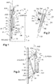
- one of the members 77 is an adjustable length cylinder 80 controlled by a button 81 visible on the figure 4 .
- a button 81 is optionally arranged on the seat.
- the extensible assembly may comprise an energy absorber 90 which is attached to one of said members 77 and to one of the arms 32.
- a member of the expandable assembly is hinged to the arm 32 of an upper mounting assembly.
- the other member of the expandable assembly is a variable length jack integral with an energy absorber which is connected to the arm 32 of a lower mounting assembly.
- one member extends partially inside a tube of the other member, being slidably mounted in this tube. At least one locking means 78, 79 can prevent the sliding of one member relative to the other.
- a first locking means is inserted into an orifice 781, 782 of the two members 76, 77 when the arms 32 are in the storage position to immobilize a member 76 relative to the other member 77.
- a second means blocking 79 is inserted into an orifice 791, 792 of the two members 76, 77 when the arms 32 are in the position of use to immobilize a member 76 relative to the other member 77.
- Each blocking means 78, 79 may comprise a guillotine 783, 793 movable in translation in a direction D2, D3 orthogonal to the extension direction D1 of the extensible assembly, and a spring 784, 794 tending to position the locking means in the orifices of the assembly extensible.
- the extensible assembly extends.
- the arms then rotate around their storage axes to reach the position of use POS4 illustrated.
- the second blocking means 79 then holds the extensible assembly in a stretched position. The reverse operation returns to the storage position.
- the seat can therefore be maneuvered to reach its sitting position.
- the seat then moves towards the floor. This displacement induces the solicitation of the energy absorber.
- the structure can also be rotated around the axis in elevation AX5.
- the pivoting arrangement 40 comprises a bar 50. This bar rises in elevation along the axis in elevation AX5 being articulated to each arm 32.
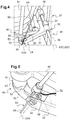
- the figure 4 illustrates an arm 32 of the seat hinged to the bar 50.
- This arm 32 is carried by a tube of the assembly assembly joint.
- a latch 38 with screws or even stops 37 make it possible to adjust the position of the arm along the transverse axis AX3 of the tube 36.
- this figure 4 shows the previously described button 81 for controlling the variable length jack 80.
- the arm comprises a female yoke crossed by a pin 92.
- the bar 50 then has a fork arranged in the female yoke around the pin 92. Where appropriate, this pin is hinged to a member of the immobilization system or according to this shown in an energy absorber 90.
- the energy absorber comprises a wire 91 forming a closed loop.
- the wire 91 extends from a free end to an end secured to the extensible assembly by surrounding the pin 92.
- Other energy absorbers are possible.
- the supporting structure 20 comprises a tube 51 arranged around the bar 50, the seat 21 being carried by the tube 51.
- the tube has a degree of freedom in rotation around the bar, and a degree of freedom in translation along this bar.
- the bar 50 comprises a first rotational immobilization means 52 comprising jaw claws.
- the bar 50 and the first immobilizing means 52 may form a single piece.
- the tube 51 comprises a second rotational immobilization means 53 comprising jaw claws.
- the tube 51 and the second immobilization means 53 may form a single piece.
- the jaw form a succession of hollows and bumps along a circular peripheral path.
- the support structure 20 comprises a headrest 23.
- the headrest may for example be carried by the bar, or by a block 22 integral with the bar.
- Such a block 22 may contain a strap retention system.
- the headrest 23 is fixed to a hinge allowing a rotational movement of the headrest 23 relative to the tube 51 of a POSV vertical position illustrated on the figure 6 towards a POSH horizontal position.
- the headrest 23 is in particular mobile about an axis orthogonal to the axis in elevation AX5.
- This headrest 23 carries a pin 60 which cooperates with a stop 61 integral with the bar 50.
- a stop 61 integral with the bar 50.
- Such an abutment may comprise a horizontal plate for example.
- the pin 60 is thus attached to the stop 61 when the headrest 23 is in the vertical position POSV.
- the first immobilization means 52 is engaged with the second immobilization means 53.
- a blocking means can be used to tend to maintain the headrest 23 in the POSV vertical position, such as an elastic member for example.
- an individual tilts the headrest 23 in its horizontal position POSH, if necessary by operating the locking means.
- the rotation of the headrest 23 induces a movement of the pin 60 relative to the stop 61.
- the pin 60 is then located under the stop 61.
- a clearance 62 in elevation then separates the stop 61 and the pin 60.
- This game is favorably superior to the depth of the hollows of the jaw immobilization means.
- a rotation of the tube 51 relative to the bar 50 about the axis in elevation AX5 induces a disengagement of the first immobilizing means 52 of the second immobilizing means 53, and consequently a translation of the tube relative to the bar .
- the bumps 531 of the second immobilization means 53 then slide on the first immobilization means 52, and reach the top of the bumps 521 of the first immobilization means 52.
- an operator can rotate the tube 51 relative to the bar 50, for example by gripping the headrest.
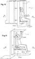
- such a folding seat makes it easy to position an individual forward of the aircraft as illustrated by figure 10 , towards the rear of the aircraft as shown in Figure 11 .
- the schematized corridor may have a step. The individual can then maneuver the length adjustable cylinder to adjust the height of the seat relative to the floor.
- AX4 folding axes and AX2 storage axes are vertical. These AX4 folding axes and storage axes AX2 are thus parallel to the axis in elevation AX5. In addition, the folding axes AX4 and the axis in elevation AX5 can be confused.
- the arms are thus provided with vertical pivots at the vertical wall 3 which allow a folding kinematics along the vertical wall 3 for storing the jump seat.
- each arm can rotate about a transverse axis AX3 of the assembly assembly, this transverse axis being orthogonal to the storage axis of the assembly assembly.
- each arm can move in rotation about a transverse axis AX3.
- each arm can translate along the transverse axis AX3.
- the articulation of a mounting assembly may thus comprise a cylinder 351 fixed to the wall extending along the transverse axis AX3 of this assembly assembly.
- This cylinder 351 may be surrounded by a slider 352 carrying a pivot hinged to the arm.
- This pivot takes the form of a rod 353 then passing through at least one orifice of the corresponding arm 32.
- the arm 32 can then rotate around the cylinder, slide along the cylinder and rotate about the pivot.
- a locking system can make it possible to immobilize the slide in translation relative to the cylinder, without, however, immobilizing it in rotation.
- a locking system has locks each suitable for real estate in translation the slide.
- the jump seat can include an immobilization system to immobilize each arm in rotation around the AX2 storage axis in the absence of efforts exerted by an individual.
- this immobilization system may comprise a retractable finger 200 in the arm 32.
- this finger 200 can be locked between the slide 352 and the wall 3 in the storage position, and can be pressed on the other side of the slide 352 in the position of use.
- the mounting structure may comprise a seat 21 hinged to a backrest 24.
- the seat 21 may be rotated about a retraction axis AX1 to reach its sitting position of the seat. figure 12 .
- the backrest 24 is then carried by the arms through the pivoting arrangement 40.
- the backrest 24 can cooperate with a leg 300.
- This pivoting arrangement 40 comprises for each mounting assembly a rod 41.
- Each rod 41 is then secured to the supporting structure 20, and if necessary the backrest 24.
- each rod is articulated to the corresponding arm 32 by a pivot 42 which allows only a rotation of the rod 41 relative to the arm 32 about the axis in elevation AX5.
- a connecting rod 43 can be secured to a rod 41.
- This rod 43 is then attached to an arrangement comprising an adjustable length cylinder 80 and / or an absorber 90. This arrangement is further secured to the supporting structure, and if appropriate to the folder 24.
- the connecting rod 43 extends from one end secured to a rod 41 to an end attached to a energy absorber 90, a length-adjustable jack 80 being attached to the energy absorber and to an edge folder.
- an individual causes the rotation of the arm 32 connected to the adjustable length cylinder 80 about the transverse axis AX3.
- the seat 21 is then close to or away from the floor.
- the figure 13 illustrates the carrier structure before a crash. Following a crash and referring to the figure 14 , the seat then moves to the floor. This displacement induces the rotation ROT of the arms 32 around their transverse axes AX3. Therefore the rod 43 performs a rotary movement. As a result, this rod 43 deforms the energy absorber 90 by traction, compression and / or torsion.
- At least one arm 32 may carry a rotary latch 44.
- Such a lock may comprise two fingers 45, 46.
- the carrier structure 20 then comprises two notches 47, 48.
- the two fingers 45, 46 can then penetrate respectively into the two notches 47, 48 when the carrier structure 20 is respectively in the first position and the second position.
- the notches can describe arcs of circle due to the particular kinematics of the supporting structure following a crash or a height adjustment.
- L-shaped links 380 of a locking system can make it possible to lock each slide along the wall.
- End stops may also be arranged to absorb shocks following a displacement of the support structure.
- the folding seat may include aforementioned organs not shown, such as for example a jack 80, an immobilization system 75.
- the Figures 16 to 19 illustrate various positions that can be reached by the jump seat 10.
- the arms are positioned in their position of use.
- the carrier structure is held in the first position POS1 by a first finger 45 of the lock 44, engaged with the notch 47.
- the first finger can be manipulated to allow a 180 degree rotation of the carrier structure 20 about the axis in elevation AX5.
- the carrier structure is then maintained in the second position POS2 by a second finger 46 of the lock 44, engaged with the notch 48.
- the arms can be positioned in their storage positions.
- the supporting structure is either maintained in the first position POS1 illustrated on the figure 18 , be maintained in the second position POS2 illustrated on the figure 19 .
- the figure 20 illustrates a variant that does not form part of the invention.
- the arms 32 are articulated to a rail 400 extending parallel to the axis in elevation AX5.
Landscapes
- Engineering & Computer Science (AREA)
- Aviation & Aerospace Engineering (AREA)
- Seats For Vehicles (AREA)
Claims (17)
- Klappsitz (10) mit einer Trägerstruktur (20), wobei die Trägerstruktur (20) mindestens eine Sitzfläche (21) umfasst, die um eine Rückzugsachse (AX1) drehbeweglich ist, wobei der Klappsitz (10) eine Befestigungsstruktur (30) zur Befestigung der Trägerstruktur (20) an einer Wand (3) umfasst,wobei die Befestigungsstruktur (30) mindestens zwei Befestigungsanordnungen (31) umfasst, wobei jede Befestigungsanordnung einen Arm (32) und ein Gelenk (35) zur Befestigung an der Wand (3) umfasst, wobei das Gelenk (35) einer Befestigungsanordnung dem Arm (32) der Befestigungsanordnung mindestens einen Rotationsfreiheitsgrad um eine Stauachse (AX2) verleiht, die vorgesehen ist, um parallel zu der Wand zu sein,die Trägerstruktur (20) an jedem Arm (32) durch eine Schwenkanordnung (40) angelenkt ist, wobei die Schwenkanordnung (40) an jedem Arm (32) entlang einer Klappachse (AX4) angelenkt ist, wobei die Klappachse (AX4) und die Stauachse (AX2) parallel zueinander sind, die Schwenkanordnung (40) der Trägerstruktur (20) in Bezug auf die Arme (32) mindestens einen Rotationsfreiheitsgrad um eine Höhenachse (AX5) verleiht, wobei jeder Arm (32) um seine Stauachse (AX2) aus einer Stauposition (POS3) zum Einfahren der Trägerstruktur (20) in eine Gebrauchsposition (POS4) drehbeweglich ist, die erreicht wird, damit eine Person auf der Trägerstruktur (20) sitzen kann,wobei die Trägerstruktur (20) zumindest, wenn sich die Arme (32) in ihren Gebrauchspositionen (POS4) befinden, um 180 Grad um die Höhenachse (AX5) von einer ersten Position (POS1) in eine zweite Position (POS2) drehbar ist.
- Klappsitz nach Anspruch 1,
dadurch gekennzeichnet, dass die Trägerstruktur (20) um 90 Grad um die Höhenachse (AX5) von der ersten Position (POS1) in eine Zwischenposition und um 90 Grad um die Höhenachse (AX5) von der Zwischenposition in die zweite Position (POS2) drehbar ist. - Klappsitz nach einem der Ansprüche 1 bis 2,
dadurch gekennzeichnet, dass die Befestigungsstruktur (30) einen Zylinder (80) mit verstellbarer Länge umfasst, der mit mindestens einem Arm (32) verbunden ist, um eine Höhe des Klappsitzes (10) in Bezug auf einen Boden einzustellen. - Klappsitz nach einem der Ansprüche 1 bis 3,
dadurch gekennzeichnet, dass die Befestigungsstruktur (30) einen Energieabsorber (90) beinhaltet, der mit mindestens einem Arm (32) verbunden ist. - Klappsitz nach einem der Ansprüche 1 bis 4,
dadurch gekennzeichnet, dass die Befestigungsstruktur (30) ein Immobilisierungssystem (75) beinhaltet, das von einem Menschen betätigbar ist, um die Arme (32) bei Bedarf zumindest in der Stauposition (POS3) zu verriegeln. - Klappsitz nach einem der Ansprüche 1 bis 5,
dadurch gekennzeichnet, dass das Gelenk (35) einer Befestigungsanordnung (31) dem Arm (32) dieser Befestigungsanordnung mindestens einen Translationsfreiheitsgrad entlang einer Querachse (AX3) verleiht, die vorgesehen ist, um parallel zu der Wand (3) zu sein. - Klappsitz nach einem der Ansprüche 1 bis 2,
dadurch gekennzeichnet, dass das Gelenk (35) einer Befestigungsanordnung dem Arm (32) der Befestigungsanordnung mindestens einen Rotationsfreiheitsgrad um eine Querachse (AX3) verleiht, die vorgesehen ist, um parallel zu der Wand (3) zu sein. - Klappsitz nach einem der Ansprüche 1, 2 und 7,
dadurch gekennzeichnet, dass die Schwenkanordnung (40) für jede Befestigungsanordnung eine Stange (41) umfasst, wobei jede Stange (41) fest mit der Trägerstruktur (20) verbunden ist und mit dem entsprechenden Arm (32) durch einen Drehpunkt (42) verbunden ist, der eine Drehung der Stange (41) in Bezug auf den Arm (32) nur um die Höhenachse (AX5) ermöglicht. - Klappsitz nach Anspruch 8,
dadurch gekennzeichnet, dass ein Lenker (43) mit einer der Stangen (41) fest verbunden ist, dass ein längenverstellbarer Zylinder (80) und/oder ein Energieabsorber (90) zwischen dem Lenker (43) und der Trägerstruktur (20) angeordnet ist, wobei jeder Arm (32) um die Stauachse (AX2) von der Stauposition (POS3) in die Gebrauchsposition (POS4) und um eine Querachse (AX3) drehbar ist, die vorgesehen ist, um parallel zu der Wand (3) zu sein. - Klappsitz nach einem der Ansprüche 8 bis 9,
dadurch gekennzeichnet, dass mindestens ein Arm (32) einen drehbaren Riegel (44) trägt, dass die Trägerstruktur (20) zwei Kerben (47, 48) aufweist, und dass der Riegel (44) zwei Finger (45, 46) aufweist, die eingerichtet sind, um in die beiden Kerben (47, 48) einzudringen, wenn sich die Trägerstruktur (20) in der ersten Position (POS1) bzw. der zweiten Position (POS2) befindet. - Klappsitz nach einem der Ansprüche 1 bis 7,dadurch gekennzeichnet, dass die Schwenkanordnung (40) eine Stange (50) aufweist, die sich in der Höhe entlang der Höhenachse (AX5) erstreckt und an jedem Arm (32) angelenkt ist, und dass die Trägerstruktur (20) ein um die Stange (50) angeordnetes Rohr (51) umfasst, wobei der Sitz (21) von dem Rohr (51) getragen ist,wobei die Stange (50) ein erstes Drehimmobilisierungsmittel (52) mit Stiften aufweist und das Rohr (51) ein zweites Drehimmobilisierungsmittel (53) mit Stiften aufweist, das mit dem ersten Drehimmobilisierungsmittel (52) zusammenwirkt, wobei eine Drehung des Rohres (51) in Bezug auf die Stange (50) um die Höhenachse (AX5) ein Lösen des ersten Drehimmobilisierungsmittels (52) vom zweiten Drehimmobilisierungsmittel (53) und dann ein Wiedereinrasten des ersten Drehimmobilisierungsmittel (52) in das zweite Drehimmobilisierungsmittel (53) bewirkt.
- Klappsitz nach Anspruch 11,
dadurch gekennzeichnet, dass die Trägerstruktur (20) eine Kopfstütze (23) umfasst, die in Bezug auf das Rohr (51) von einer vertikalen Position (POSV) in eine horizontale Position (POSH) drehbeweglich ist, wobei die Kopfstütze (23) einen Stift (60) trägt, der mit einem Anschlag (61) zusammenwirkt, der mit der Stange (50) fest verbunden ist, dass der Stift (60) an dem Anschlag (61) anliegt, wenn sich die Kopfstütze (23) in der vertikalen Position (POSV) befindet, und dass der Stift (60) unter dem Anschlag (61) mit Spiel (62) in der Höhe zwischen dem Anschlag (61) und dem Stift (60) angeordnet ist, wenn sich die Kopfstütze (23) in der horizontalen Position (POSH) befindet, um die Drehbewegung des Rohres (51) in Bezug auf die Stange (50) zu ermöglichen. - Klappsitz nach Anspruch 5,
dadurch gekennzeichnet, dass das Immobilisierungssystem (75) eine ausziehbare Anordnung mit zwei relativ zueinander beweglichen Elementen (76, 77) umfasst, wobei eines der beiden Elemente (76) mit einem Arm und das andere Element (77) mit dem anderen Arm gelenkig verbunden ist, wobei mindestens ein translatorisch bewegliches Verriegelungsmittel (78, 79) in einer Öffnung der beiden Elemente (76, 77) angeordnet ist, wenn sich die Arme (32) in der Stauposition befinden, um ein Element (76) relativ zu dem anderen Element (77) zu immobilisieren. - Klappsitz nach Anspruch 13 und Anspruch 3,
dadurch gekennzeichnet, dass eines der Elemente (77) der längenverstellbare Zylinder ist. - Klappsitz nach Anspruch 13 und Anspruch 4,
dadurch gekennzeichnet, dass der Energieabsorber (90) an einem der Elemente (77) und einem der Arme (32) befestigt ist. - Flugzeug (1) mit einer Wand (3), dadurch gekennzeichnet, dass das Flugzeug (1) einen Klappsitz (10) nach einem der Ansprüche 1 bis 15 aufweist, wobei die Gelenke (35) von der Wand (3) getragen sind.
- Luftfahrzeuge nach Anspruch 16,
dadurch gekennzeichnet, dass das Flugzeug (1) einen Korridor (2) aufweist, der sich in Längsrichtung vom Heck (AR) des Flugzeugs (1) zum Bug (AV) des Flugzeugs (1) erstreckt, wobei die Wand (3) den Korridor (2) zumindest teilweise quer begrenzt und die erste Position (POS1) eine Person zum Bug (AV) des Flugzeugs (1) positioniert und die zweite Position (POS2) die Person zum Heck (AR) des Flugzeugs (1) positioniert.
Applications Claiming Priority (1)
| Application Number | Priority Date | Filing Date | Title |
|---|---|---|---|
| FR1601076A FR3053659B1 (fr) | 2016-07-11 | 2016-07-11 | Strapontin, et vehicule muni de ce strapontin |
Publications (2)
| Publication Number | Publication Date |
|---|---|
| EP3269643A1 EP3269643A1 (de) | 2018-01-17 |
| EP3269643B1 true EP3269643B1 (de) | 2019-04-03 |
Family
ID=57113392
Family Applications (1)
| Application Number | Title | Priority Date | Filing Date |
|---|---|---|---|
| EP17178455.6A Active EP3269643B1 (de) | 2016-07-11 | 2017-06-28 | Klappsitz und mit diesem klappsitz ausgestattetes fahrzeug |
Country Status (3)
| Country | Link |
|---|---|
| US (1) | US10479508B2 (de) |
| EP (1) | EP3269643B1 (de) |
| FR (1) | FR3053659B1 (de) |
Families Citing this family (5)
| Publication number | Priority date | Publication date | Assignee | Title |
|---|---|---|---|---|
| US10689120B2 (en) * | 2016-08-29 | 2020-06-23 | Textron Innovations, Inc. | Stowable reversible seat |
| US11535381B2 (en) | 2021-04-23 | 2022-12-27 | B/E Aerospace, Inc. | Deployable cabin attendant seat system |
| US11642990B2 (en) * | 2021-07-21 | 2023-05-09 | George Seifien | Car seat swivel assembly |
| KR20230091576A (ko) * | 2021-12-16 | 2023-06-23 | 현대자동차주식회사 | 쿠션 팁업타입 차량용 시트 |
| US11820265B2 (en) * | 2022-02-03 | 2023-11-21 | Brose Fahrzeugteile SE & Co. Kommanditgesellschaft, Coburg | Vehicle seat |
Family Cites Families (10)
| Publication number | Priority date | Publication date | Assignee | Title |
|---|---|---|---|---|
| US4740030A (en) | 1984-07-12 | 1988-04-26 | Nordskog Robert A | Jump seat assembly and seat with improved safety belt array |
| GB2323526B (en) | 1994-12-03 | 1998-11-18 | Magna Seating Systems Ltd | Folding seating unit for a vehicle |
| FR2863558B1 (fr) | 2003-12-10 | 2006-03-31 | Airbus | Procede pour moduler l'espace interieur d'un vehicule et siege pour la mise en oeuvre de ce procede |
| FR2930520B1 (fr) | 2008-04-28 | 2010-08-20 | Eurocopter France | Siege anti-ecrasement d'un vehicule |
| US8770659B2 (en) | 2011-02-04 | 2014-07-08 | Ami Industries, Inc. | Self-stowing jumpseat for aircraft |
| EP2718184B1 (de) * | 2011-06-10 | 2016-08-31 | Zodiac Seats US LLC | Passagiersitzanordnung |
| FR2980773B1 (fr) | 2011-09-30 | 2013-10-25 | Airbus Operations Sas | Strapontin pour cockpit d'aeronef et partie avant d'aeronef equipee d'un tel strapontin |
| DE102011116521A1 (de) | 2011-10-20 | 2013-04-25 | Airbus Operations Gmbh | Drehbarer Flugbegleitersitz und Flugzeugmonumentbaugruppe mit einem drehbaren Flugbegleitersitz |
| US20140319275A1 (en) * | 2013-04-29 | 2014-10-30 | C&D Zodiac, Inc. | Compact cabin attendant seat stowage |
| US9856024B2 (en) * | 2013-06-18 | 2018-01-02 | B/E Aerospace, Inc. | Compact aircraft cabin attendant seat |
-
2016
- 2016-07-11 FR FR1601076A patent/FR3053659B1/fr not_active Expired - Fee Related
-
2017
- 2017-06-28 EP EP17178455.6A patent/EP3269643B1/de active Active
- 2017-07-07 US US15/644,409 patent/US10479508B2/en not_active Expired - Fee Related
Non-Patent Citations (1)
| Title |
|---|
| None * |
Also Published As
| Publication number | Publication date |
|---|---|
| US10479508B2 (en) | 2019-11-19 |
| FR3053659B1 (fr) | 2019-07-19 |
| EP3269643A1 (de) | 2018-01-17 |
| US20180009534A1 (en) | 2018-01-11 |
| FR3053659A1 (fr) | 2018-01-12 |
Similar Documents
| Publication | Publication Date | Title |
|---|---|---|
| EP3269643B1 (de) | Klappsitz und mit diesem klappsitz ausgestattetes fahrzeug | |
| EP3374264B1 (de) | Flugzeugsitz für crew | |
| EP3060428B1 (de) | Vorrichtung zum verriegeln eines faltelements für einen fahrzeugsitz in einer bestimmten position | |
| EP1778524B1 (de) | Sicherheitsvorrichtung zur verwendung im falle eines fahrzeugüberschlags | |
| FR2950607A1 (fr) | Siege pour appareils volants motorises, integrant des moyens de protection du passager en cas de crash | |
| EP3619114B1 (de) | Mit einem system zur verriegelung des tabletttischs im fall eines aufpralls ausgestatteter sitz | |
| FR3116771A1 (fr) | Siège de véhicule à assise et dossiers inclinables pour faciliter l’accès aux places arrière | |
| EP3368417B1 (de) | Anordnung mit einem passagiersitz und einem sitz für bordpersonal | |
| EP4259523B1 (de) | Sitzeinheit mit faltbarem sichtschutzschild | |
| EP0026510A1 (de) | Vorrichtung zum Überführen eines Körperbehinderten von einem Rollstuhl in ein Kraftfahrzeug | |
| EP3597478A1 (de) | Sitz, der ein ausziehbares brettchen umfasst | |
| EP2808199B1 (de) | Klappsitz für Fahrzeugkabine, der eine Vielzahl von Gelenkachsen umfasst | |
| FR2919235A1 (fr) | Banquette arriere escamotable contre le pavillon d'un vehicule automobile et son procede d'escamotage. | |
| WO1997041000A1 (fr) | Siege de vehicule de transport en commun susceptible d'etre transforme en couchette | |
| EP0592273A2 (de) | Fahrzeugsitz mit einer teilbeweglichen Rückenlehne | |
| FR2969058A1 (fr) | Siege de vehicule automobile dote d'un dispositif anti sous-marinage ameliore | |
| FR2823164A1 (fr) | Dispositif de protection de passagers occupant les sieges arriere d'un vehicule automobile | |
| FR3071201B1 (fr) | Accoudoir de pilier central | |
| EP2095992B1 (de) | Kraftfahrzeugsitz mit versenkbarer Kopfstütze | |
| EP1767395B1 (de) | Klappsitz für Fahrzeugskofferraum | |
| EP3877211B1 (de) | Versenkbarer sitz für ein kraftfahrzeug und fahrzeug mit solch einem sitz | |
| WO2010122263A1 (fr) | Siege escamotable pour vehicule automobile, procede d'escamotage de ce siege et vehicule automobile comprenant au moins un tel siege | |
| FR2897565A1 (fr) | Siege repliable de vehicule automobile | |
| FR2946579A1 (fr) | Vehicule comprenant une cabine dans laquelle une banquette et un siege sont montes de maniere amovible,le siege ne pouvant etre monte qu'en presence de la banquette. | |
| FR3152491A1 (fr) | Ouvrant facilitant l'accès à un siège pour une personne à mobilité réduite ou a forte corpulence |
Legal Events
| Date | Code | Title | Description |
|---|---|---|---|
| PUAI | Public reference made under article 153(3) epc to a published international application that has entered the european phase |
Free format text: ORIGINAL CODE: 0009012 |
|
| STAA | Information on the status of an ep patent application or granted ep patent |
Free format text: STATUS: THE APPLICATION HAS BEEN PUBLISHED |
|
| AK | Designated contracting states |
Kind code of ref document: A1 Designated state(s): AL AT BE BG CH CY CZ DE DK EE ES FI FR GB GR HR HU IE IS IT LI LT LU LV MC MK MT NL NO PL PT RO RS SE SI SK SM TR |
|
| AX | Request for extension of the european patent |
Extension state: BA ME |
|
| STAA | Information on the status of an ep patent application or granted ep patent |
Free format text: STATUS: REQUEST FOR EXAMINATION WAS MADE |
|
| 17P | Request for examination filed |
Effective date: 20180326 |
|
| RBV | Designated contracting states (corrected) |
Designated state(s): AL AT BE BG CH CY CZ DE DK EE ES FI FR GB GR HR HU IE IS IT LI LT LU LV MC MK MT NL NO PL PT RO RS SE SI SK SM TR |
|
| RIC1 | Information provided on ipc code assigned before grant |
Ipc: B64D 11/06 20060101AFI20181011BHEP |
|
| GRAP | Despatch of communication of intention to grant a patent |
Free format text: ORIGINAL CODE: EPIDOSNIGR1 |
|
| STAA | Information on the status of an ep patent application or granted ep patent |
Free format text: STATUS: GRANT OF PATENT IS INTENDED |
|
| INTG | Intention to grant announced |
Effective date: 20181122 |
|
| GRAS | Grant fee paid |
Free format text: ORIGINAL CODE: EPIDOSNIGR3 |
|
| GRAA | (expected) grant |
Free format text: ORIGINAL CODE: 0009210 |
|
| STAA | Information on the status of an ep patent application or granted ep patent |
Free format text: STATUS: THE PATENT HAS BEEN GRANTED |
|
| AK | Designated contracting states |
Kind code of ref document: B1 Designated state(s): AL AT BE BG CH CY CZ DE DK EE ES FI FR GB GR HR HU IE IS IT LI LT LU LV MC MK MT NL NO PL PT RO RS SE SI SK SM TR |
|
| REG | Reference to a national code |
Ref country code: GB Ref legal event code: FG4D Free format text: NOT ENGLISH |
|
| REG | Reference to a national code |
Ref country code: CH Ref legal event code: EP Ref country code: AT Ref legal event code: REF Ref document number: 1115430 Country of ref document: AT Kind code of ref document: T Effective date: 20190415 |
|
| REG | Reference to a national code |
Ref country code: DE Ref legal event code: R096 Ref document number: 602017003045 Country of ref document: DE |
|
| REG | Reference to a national code |
Ref country code: IE Ref legal event code: FG4D Free format text: LANGUAGE OF EP DOCUMENT: FRENCH |
|
| REG | Reference to a national code |
Ref country code: NL Ref legal event code: MP Effective date: 20190403 |
|
| REG | Reference to a national code |
Ref country code: LT Ref legal event code: MG4D |
|
| REG | Reference to a national code |
Ref country code: AT Ref legal event code: MK05 Ref document number: 1115430 Country of ref document: AT Kind code of ref document: T Effective date: 20190403 |
|
| PG25 | Lapsed in a contracting state [announced via postgrant information from national office to epo] |
Ref country code: NL Free format text: LAPSE BECAUSE OF FAILURE TO SUBMIT A TRANSLATION OF THE DESCRIPTION OR TO PAY THE FEE WITHIN THE PRESCRIBED TIME-LIMIT Effective date: 20190403 |
|
| PG25 | Lapsed in a contracting state [announced via postgrant information from national office to epo] |
Ref country code: FI Free format text: LAPSE BECAUSE OF FAILURE TO SUBMIT A TRANSLATION OF THE DESCRIPTION OR TO PAY THE FEE WITHIN THE PRESCRIBED TIME-LIMIT Effective date: 20190403 Ref country code: NO Free format text: LAPSE BECAUSE OF FAILURE TO SUBMIT A TRANSLATION OF THE DESCRIPTION OR TO PAY THE FEE WITHIN THE PRESCRIBED TIME-LIMIT Effective date: 20190703 Ref country code: LT Free format text: LAPSE BECAUSE OF FAILURE TO SUBMIT A TRANSLATION OF THE DESCRIPTION OR TO PAY THE FEE WITHIN THE PRESCRIBED TIME-LIMIT Effective date: 20190403 Ref country code: HR Free format text: LAPSE BECAUSE OF FAILURE TO SUBMIT A TRANSLATION OF THE DESCRIPTION OR TO PAY THE FEE WITHIN THE PRESCRIBED TIME-LIMIT Effective date: 20190403 Ref country code: SE Free format text: LAPSE BECAUSE OF FAILURE TO SUBMIT A TRANSLATION OF THE DESCRIPTION OR TO PAY THE FEE WITHIN THE PRESCRIBED TIME-LIMIT Effective date: 20190403 Ref country code: PT Free format text: LAPSE BECAUSE OF FAILURE TO SUBMIT A TRANSLATION OF THE DESCRIPTION OR TO PAY THE FEE WITHIN THE PRESCRIBED TIME-LIMIT Effective date: 20190803 Ref country code: AL Free format text: LAPSE BECAUSE OF FAILURE TO SUBMIT A TRANSLATION OF THE DESCRIPTION OR TO PAY THE FEE WITHIN THE PRESCRIBED TIME-LIMIT Effective date: 20190403 Ref country code: ES Free format text: LAPSE BECAUSE OF FAILURE TO SUBMIT A TRANSLATION OF THE DESCRIPTION OR TO PAY THE FEE WITHIN THE PRESCRIBED TIME-LIMIT Effective date: 20190403 Ref country code: CZ Free format text: LAPSE BECAUSE OF FAILURE TO SUBMIT A TRANSLATION OF THE DESCRIPTION OR TO PAY THE FEE WITHIN THE PRESCRIBED TIME-LIMIT Effective date: 20190403 |
|
| PG25 | Lapsed in a contracting state [announced via postgrant information from national office to epo] |
Ref country code: BG Free format text: LAPSE BECAUSE OF FAILURE TO SUBMIT A TRANSLATION OF THE DESCRIPTION OR TO PAY THE FEE WITHIN THE PRESCRIBED TIME-LIMIT Effective date: 20190703 Ref country code: RS Free format text: LAPSE BECAUSE OF FAILURE TO SUBMIT A TRANSLATION OF THE DESCRIPTION OR TO PAY THE FEE WITHIN THE PRESCRIBED TIME-LIMIT Effective date: 20190403 Ref country code: PL Free format text: LAPSE BECAUSE OF FAILURE TO SUBMIT A TRANSLATION OF THE DESCRIPTION OR TO PAY THE FEE WITHIN THE PRESCRIBED TIME-LIMIT Effective date: 20190403 Ref country code: GR Free format text: LAPSE BECAUSE OF FAILURE TO SUBMIT A TRANSLATION OF THE DESCRIPTION OR TO PAY THE FEE WITHIN THE PRESCRIBED TIME-LIMIT Effective date: 20190704 Ref country code: LV Free format text: LAPSE BECAUSE OF FAILURE TO SUBMIT A TRANSLATION OF THE DESCRIPTION OR TO PAY THE FEE WITHIN THE PRESCRIBED TIME-LIMIT Effective date: 20190403 |
|
| PG25 | Lapsed in a contracting state [announced via postgrant information from national office to epo] |
Ref country code: IS Free format text: LAPSE BECAUSE OF FAILURE TO SUBMIT A TRANSLATION OF THE DESCRIPTION OR TO PAY THE FEE WITHIN THE PRESCRIBED TIME-LIMIT Effective date: 20190803 Ref country code: AT Free format text: LAPSE BECAUSE OF FAILURE TO SUBMIT A TRANSLATION OF THE DESCRIPTION OR TO PAY THE FEE WITHIN THE PRESCRIBED TIME-LIMIT Effective date: 20190403 |
|
| REG | Reference to a national code |
Ref country code: DE Ref legal event code: R097 Ref document number: 602017003045 Country of ref document: DE |
|
| PG25 | Lapsed in a contracting state [announced via postgrant information from national office to epo] |
Ref country code: SK Free format text: LAPSE BECAUSE OF FAILURE TO SUBMIT A TRANSLATION OF THE DESCRIPTION OR TO PAY THE FEE WITHIN THE PRESCRIBED TIME-LIMIT Effective date: 20190403 Ref country code: RO Free format text: LAPSE BECAUSE OF FAILURE TO SUBMIT A TRANSLATION OF THE DESCRIPTION OR TO PAY THE FEE WITHIN THE PRESCRIBED TIME-LIMIT Effective date: 20190403 Ref country code: MC Free format text: LAPSE BECAUSE OF FAILURE TO SUBMIT A TRANSLATION OF THE DESCRIPTION OR TO PAY THE FEE WITHIN THE PRESCRIBED TIME-LIMIT Effective date: 20190403 Ref country code: DK Free format text: LAPSE BECAUSE OF FAILURE TO SUBMIT A TRANSLATION OF THE DESCRIPTION OR TO PAY THE FEE WITHIN THE PRESCRIBED TIME-LIMIT Effective date: 20190403 Ref country code: EE Free format text: LAPSE BECAUSE OF FAILURE TO SUBMIT A TRANSLATION OF THE DESCRIPTION OR TO PAY THE FEE WITHIN THE PRESCRIBED TIME-LIMIT Effective date: 20190403 |
|
| PLBE | No opposition filed within time limit |
Free format text: ORIGINAL CODE: 0009261 |
|
| STAA | Information on the status of an ep patent application or granted ep patent |
Free format text: STATUS: NO OPPOSITION FILED WITHIN TIME LIMIT |
|
| PG25 | Lapsed in a contracting state [announced via postgrant information from national office to epo] |
Ref country code: SM Free format text: LAPSE BECAUSE OF FAILURE TO SUBMIT A TRANSLATION OF THE DESCRIPTION OR TO PAY THE FEE WITHIN THE PRESCRIBED TIME-LIMIT Effective date: 20190403 |
|
| 26N | No opposition filed |
Effective date: 20200106 |
|
| REG | Reference to a national code |
Ref country code: BE Ref legal event code: MM Effective date: 20190630 |
|
| PG25 | Lapsed in a contracting state [announced via postgrant information from national office to epo] |
Ref country code: TR Free format text: LAPSE BECAUSE OF FAILURE TO SUBMIT A TRANSLATION OF THE DESCRIPTION OR TO PAY THE FEE WITHIN THE PRESCRIBED TIME-LIMIT Effective date: 20190403 |
|
| PG25 | Lapsed in a contracting state [announced via postgrant information from national office to epo] |
Ref country code: IE Free format text: LAPSE BECAUSE OF NON-PAYMENT OF DUE FEES Effective date: 20190628 |
|
| PG25 | Lapsed in a contracting state [announced via postgrant information from national office to epo] |
Ref country code: SI Free format text: LAPSE BECAUSE OF FAILURE TO SUBMIT A TRANSLATION OF THE DESCRIPTION OR TO PAY THE FEE WITHIN THE PRESCRIBED TIME-LIMIT Effective date: 20190403 Ref country code: LU Free format text: LAPSE BECAUSE OF NON-PAYMENT OF DUE FEES Effective date: 20190628 Ref country code: BE Free format text: LAPSE BECAUSE OF NON-PAYMENT OF DUE FEES Effective date: 20190630 |
|
| REG | Reference to a national code |
Ref country code: CH Ref legal event code: PL |
|
| PG25 | Lapsed in a contracting state [announced via postgrant information from national office to epo] |
Ref country code: LI Free format text: LAPSE BECAUSE OF NON-PAYMENT OF DUE FEES Effective date: 20200630 Ref country code: CH Free format text: LAPSE BECAUSE OF NON-PAYMENT OF DUE FEES Effective date: 20200630 |
|
| PG25 | Lapsed in a contracting state [announced via postgrant information from national office to epo] |
Ref country code: CY Free format text: LAPSE BECAUSE OF FAILURE TO SUBMIT A TRANSLATION OF THE DESCRIPTION OR TO PAY THE FEE WITHIN THE PRESCRIBED TIME-LIMIT Effective date: 20190403 |
|
| PG25 | Lapsed in a contracting state [announced via postgrant information from national office to epo] |
Ref country code: HU Free format text: LAPSE BECAUSE OF FAILURE TO SUBMIT A TRANSLATION OF THE DESCRIPTION OR TO PAY THE FEE WITHIN THE PRESCRIBED TIME-LIMIT; INVALID AB INITIO Effective date: 20170628 Ref country code: MT Free format text: LAPSE BECAUSE OF FAILURE TO SUBMIT A TRANSLATION OF THE DESCRIPTION OR TO PAY THE FEE WITHIN THE PRESCRIBED TIME-LIMIT Effective date: 20190403 |
|
| GBPC | Gb: european patent ceased through non-payment of renewal fee |
Effective date: 20210628 |
|
| PG25 | Lapsed in a contracting state [announced via postgrant information from national office to epo] |
Ref country code: GB Free format text: LAPSE BECAUSE OF NON-PAYMENT OF DUE FEES Effective date: 20210628 |
|
| PG25 | Lapsed in a contracting state [announced via postgrant information from national office to epo] |
Ref country code: MK Free format text: LAPSE BECAUSE OF FAILURE TO SUBMIT A TRANSLATION OF THE DESCRIPTION OR TO PAY THE FEE WITHIN THE PRESCRIBED TIME-LIMIT Effective date: 20190403 |
|
| P01 | Opt-out of the competence of the unified patent court (upc) registered |
Effective date: 20230530 |
|
| PGFP | Annual fee paid to national office [announced via postgrant information from national office to epo] |
Ref country code: DE Payment date: 20250618 Year of fee payment: 9 |
|
| PGFP | Annual fee paid to national office [announced via postgrant information from national office to epo] |
Ref country code: FR Payment date: 20250625 Year of fee payment: 9 |
|
| PGFP | Annual fee paid to national office [announced via postgrant information from national office to epo] |
Ref country code: IT Payment date: 20250624 Year of fee payment: 9 |