EP3269532A1 - Verfahren zum fügen zweier faserverbund-fügepartner - Google Patents
Verfahren zum fügen zweier faserverbund-fügepartner Download PDFInfo
- Publication number
- EP3269532A1 EP3269532A1 EP17177178.5A EP17177178A EP3269532A1 EP 3269532 A1 EP3269532 A1 EP 3269532A1 EP 17177178 A EP17177178 A EP 17177178A EP 3269532 A1 EP3269532 A1 EP 3269532A1
- Authority
- EP
- European Patent Office
- Prior art keywords
- fiber composite
- joining partner
- composite joining
- adhesive material
- matrix material
- Prior art date
- Legal status (The legal status is an assumption and is not a legal conclusion. Google has not performed a legal analysis and makes no representation as to the accuracy of the status listed.)
- Granted
Links
Images

Classifications
-
- B—PERFORMING OPERATIONS; TRANSPORTING
- B29—WORKING OF PLASTICS; WORKING OF SUBSTANCES IN A PLASTIC STATE IN GENERAL
- B29C—SHAPING OR JOINING OF PLASTICS; SHAPING OF MATERIAL IN A PLASTIC STATE, NOT OTHERWISE PROVIDED FOR; AFTER-TREATMENT OF THE SHAPED PRODUCTS, e.g. REPAIRING
- B29C65/00—Joining or sealing of preformed parts, e.g. welding of plastics materials; Apparatus therefor
- B29C65/02—Joining or sealing of preformed parts, e.g. welding of plastics materials; Apparatus therefor by heating, with or without pressure
-
- B—PERFORMING OPERATIONS; TRANSPORTING
- B29—WORKING OF PLASTICS; WORKING OF SUBSTANCES IN A PLASTIC STATE IN GENERAL
- B29C—SHAPING OR JOINING OF PLASTICS; SHAPING OF MATERIAL IN A PLASTIC STATE, NOT OTHERWISE PROVIDED FOR; AFTER-TREATMENT OF THE SHAPED PRODUCTS, e.g. REPAIRING
- B29C65/00—Joining or sealing of preformed parts, e.g. welding of plastics materials; Apparatus therefor
- B29C65/48—Joining or sealing of preformed parts, e.g. welding of plastics materials; Apparatus therefor using adhesives, i.e. using supplementary joining material; solvent bonding
- B29C65/4805—Joining or sealing of preformed parts, e.g. welding of plastics materials; Apparatus therefor using adhesives, i.e. using supplementary joining material; solvent bonding characterised by the type of adhesives
- B29C65/483—Reactive adhesives, e.g. chemically curing adhesives
- B29C65/4835—Heat curing adhesives
-
- B—PERFORMING OPERATIONS; TRANSPORTING
- B29—WORKING OF PLASTICS; WORKING OF SUBSTANCES IN A PLASTIC STATE IN GENERAL
- B29C—SHAPING OR JOINING OF PLASTICS; SHAPING OF MATERIAL IN A PLASTIC STATE, NOT OTHERWISE PROVIDED FOR; AFTER-TREATMENT OF THE SHAPED PRODUCTS, e.g. REPAIRING
- B29C65/00—Joining or sealing of preformed parts, e.g. welding of plastics materials; Apparatus therefor
- B29C65/78—Means for handling the parts to be joined, e.g. for making containers or hollow articles, e.g. means for handling sheets, plates, web-like materials, tubular articles, hollow articles or elements to be joined therewith; Means for discharging the joined articles from the joining apparatus
- B29C65/7802—Positioning the parts to be joined, e.g. aligning, indexing or centring
- B29C65/782—Positioning the parts to be joined, e.g. aligning, indexing or centring by setting the gap between the parts to be joined
-
- B—PERFORMING OPERATIONS; TRANSPORTING
- B29—WORKING OF PLASTICS; WORKING OF SUBSTANCES IN A PLASTIC STATE IN GENERAL
- B29C—SHAPING OR JOINING OF PLASTICS; SHAPING OF MATERIAL IN A PLASTIC STATE, NOT OTHERWISE PROVIDED FOR; AFTER-TREATMENT OF THE SHAPED PRODUCTS, e.g. REPAIRING
- B29C66/00—General aspects of processes or apparatus for joining preformed parts
- B29C66/01—General aspects dealing with the joint area or with the area to be joined
- B29C66/05—Particular design of joint configurations
- B29C66/10—Particular design of joint configurations particular design of the joint cross-sections
- B29C66/11—Joint cross-sections comprising a single joint-segment, i.e. one of the parts to be joined comprising a single joint-segment in the joint cross-section
- B29C66/112—Single lapped joints
- B29C66/1122—Single lap to lap joints, i.e. overlap joints
-
- B—PERFORMING OPERATIONS; TRANSPORTING
- B29—WORKING OF PLASTICS; WORKING OF SUBSTANCES IN A PLASTIC STATE IN GENERAL
- B29C—SHAPING OR JOINING OF PLASTICS; SHAPING OF MATERIAL IN A PLASTIC STATE, NOT OTHERWISE PROVIDED FOR; AFTER-TREATMENT OF THE SHAPED PRODUCTS, e.g. REPAIRING
- B29C66/00—General aspects of processes or apparatus for joining preformed parts
- B29C66/40—General aspects of joining substantially flat articles, e.g. plates, sheets or web-like materials; Making flat seams in tubular or hollow articles; Joining single elements to substantially flat surfaces
- B29C66/41—Joining substantially flat articles ; Making flat seams in tubular or hollow articles
- B29C66/45—Joining of substantially the whole surface of the articles
-
- B—PERFORMING OPERATIONS; TRANSPORTING
- B29—WORKING OF PLASTICS; WORKING OF SUBSTANCES IN A PLASTIC STATE IN GENERAL
- B29C—SHAPING OR JOINING OF PLASTICS; SHAPING OF MATERIAL IN A PLASTIC STATE, NOT OTHERWISE PROVIDED FOR; AFTER-TREATMENT OF THE SHAPED PRODUCTS, e.g. REPAIRING
- B29C66/00—General aspects of processes or apparatus for joining preformed parts
- B29C66/40—General aspects of joining substantially flat articles, e.g. plates, sheets or web-like materials; Making flat seams in tubular or hollow articles; Joining single elements to substantially flat surfaces
- B29C66/47—Joining single elements to sheets, plates or other substantially flat surfaces
- B29C66/474—Joining single elements to sheets, plates or other substantially flat surfaces said single elements being substantially non-flat
-
- B—PERFORMING OPERATIONS; TRANSPORTING
- B29—WORKING OF PLASTICS; WORKING OF SUBSTANCES IN A PLASTIC STATE IN GENERAL
- B29C—SHAPING OR JOINING OF PLASTICS; SHAPING OF MATERIAL IN A PLASTIC STATE, NOT OTHERWISE PROVIDED FOR; AFTER-TREATMENT OF THE SHAPED PRODUCTS, e.g. REPAIRING
- B29C66/00—General aspects of processes or apparatus for joining preformed parts
- B29C66/70—General aspects of processes or apparatus for joining preformed parts characterised by the composition, physical properties or the structure of the material of the parts to be joined; Joining with non-plastics material
- B29C66/72—General aspects of processes or apparatus for joining preformed parts characterised by the composition, physical properties or the structure of the material of the parts to be joined; Joining with non-plastics material characterised by the structure of the material of the parts to be joined
- B29C66/721—Fibre-reinforced materials
-
- B—PERFORMING OPERATIONS; TRANSPORTING
- B29—WORKING OF PLASTICS; WORKING OF SUBSTANCES IN A PLASTIC STATE IN GENERAL
- B29C—SHAPING OR JOINING OF PLASTICS; SHAPING OF MATERIAL IN A PLASTIC STATE, NOT OTHERWISE PROVIDED FOR; AFTER-TREATMENT OF THE SHAPED PRODUCTS, e.g. REPAIRING
- B29C66/00—General aspects of processes or apparatus for joining preformed parts
- B29C66/70—General aspects of processes or apparatus for joining preformed parts characterised by the composition, physical properties or the structure of the material of the parts to be joined; Joining with non-plastics material
- B29C66/73—General aspects of processes or apparatus for joining preformed parts characterised by the composition, physical properties or the structure of the material of the parts to be joined; Joining with non-plastics material characterised by the intensive physical properties of the material of the parts to be joined, by the optical properties of the material of the parts to be joined, by the extensive physical properties of the parts to be joined, by the state of the material of the parts to be joined or by the material of the parts to be joined being a thermoplastic or a thermoset
- B29C66/731—General aspects of processes or apparatus for joining preformed parts characterised by the composition, physical properties or the structure of the material of the parts to be joined; Joining with non-plastics material characterised by the intensive physical properties of the material of the parts to be joined, by the optical properties of the material of the parts to be joined, by the extensive physical properties of the parts to be joined, by the state of the material of the parts to be joined or by the material of the parts to be joined being a thermoplastic or a thermoset characterised by the intensive physical properties of the material of the parts to be joined
- B29C66/7311—Thermal properties
- B29C66/73117—Tg, i.e. glass transition temperature
-
- B—PERFORMING OPERATIONS; TRANSPORTING
- B29—WORKING OF PLASTICS; WORKING OF SUBSTANCES IN A PLASTIC STATE IN GENERAL
- B29C—SHAPING OR JOINING OF PLASTICS; SHAPING OF MATERIAL IN A PLASTIC STATE, NOT OTHERWISE PROVIDED FOR; AFTER-TREATMENT OF THE SHAPED PRODUCTS, e.g. REPAIRING
- B29C66/00—General aspects of processes or apparatus for joining preformed parts
- B29C66/70—General aspects of processes or apparatus for joining preformed parts characterised by the composition, physical properties or the structure of the material of the parts to be joined; Joining with non-plastics material
- B29C66/73—General aspects of processes or apparatus for joining preformed parts characterised by the composition, physical properties or the structure of the material of the parts to be joined; Joining with non-plastics material characterised by the intensive physical properties of the material of the parts to be joined, by the optical properties of the material of the parts to be joined, by the extensive physical properties of the parts to be joined, by the state of the material of the parts to be joined or by the material of the parts to be joined being a thermoplastic or a thermoset
- B29C66/737—General aspects of processes or apparatus for joining preformed parts characterised by the composition, physical properties or the structure of the material of the parts to be joined; Joining with non-plastics material characterised by the intensive physical properties of the material of the parts to be joined, by the optical properties of the material of the parts to be joined, by the extensive physical properties of the parts to be joined, by the state of the material of the parts to be joined or by the material of the parts to be joined being a thermoplastic or a thermoset characterised by the state of the material of the parts to be joined
- B29C66/7375—General aspects of processes or apparatus for joining preformed parts characterised by the composition, physical properties or the structure of the material of the parts to be joined; Joining with non-plastics material characterised by the intensive physical properties of the material of the parts to be joined, by the optical properties of the material of the parts to be joined, by the extensive physical properties of the parts to be joined, by the state of the material of the parts to be joined or by the material of the parts to be joined being a thermoplastic or a thermoset characterised by the state of the material of the parts to be joined uncured, partially cured or fully cured
- B29C66/73753—General aspects of processes or apparatus for joining preformed parts characterised by the composition, physical properties or the structure of the material of the parts to be joined; Joining with non-plastics material characterised by the intensive physical properties of the material of the parts to be joined, by the optical properties of the material of the parts to be joined, by the extensive physical properties of the parts to be joined, by the state of the material of the parts to be joined or by the material of the parts to be joined being a thermoplastic or a thermoset characterised by the state of the material of the parts to be joined uncured, partially cured or fully cured the to-be-joined area of at least one of the parts to be joined being partially cured, i.e. partially cross-linked, partially vulcanized
-
- B—PERFORMING OPERATIONS; TRANSPORTING
- B29—WORKING OF PLASTICS; WORKING OF SUBSTANCES IN A PLASTIC STATE IN GENERAL
- B29C—SHAPING OR JOINING OF PLASTICS; SHAPING OF MATERIAL IN A PLASTIC STATE, NOT OTHERWISE PROVIDED FOR; AFTER-TREATMENT OF THE SHAPED PRODUCTS, e.g. REPAIRING
- B29C66/00—General aspects of processes or apparatus for joining preformed parts
- B29C66/90—Measuring or controlling the joining process
- B29C66/91—Measuring or controlling the joining process by measuring or controlling the temperature, the heat or the thermal flux
- B29C66/914—Measuring or controlling the joining process by measuring or controlling the temperature, the heat or the thermal flux by controlling or regulating the temperature, the heat or the thermal flux
- B29C66/9141—Measuring or controlling the joining process by measuring or controlling the temperature, the heat or the thermal flux by controlling or regulating the temperature, the heat or the thermal flux by controlling or regulating the temperature
- B29C66/91411—Measuring or controlling the joining process by measuring or controlling the temperature, the heat or the thermal flux by controlling or regulating the temperature, the heat or the thermal flux by controlling or regulating the temperature of the parts to be joined, e.g. the joining process taking the temperature of the parts to be joined into account
-
- B—PERFORMING OPERATIONS; TRANSPORTING
- B29—WORKING OF PLASTICS; WORKING OF SUBSTANCES IN A PLASTIC STATE IN GENERAL
- B29C—SHAPING OR JOINING OF PLASTICS; SHAPING OF MATERIAL IN A PLASTIC STATE, NOT OTHERWISE PROVIDED FOR; AFTER-TREATMENT OF THE SHAPED PRODUCTS, e.g. REPAIRING
- B29C66/00—General aspects of processes or apparatus for joining preformed parts
- B29C66/90—Measuring or controlling the joining process
- B29C66/91—Measuring or controlling the joining process by measuring or controlling the temperature, the heat or the thermal flux
- B29C66/914—Measuring or controlling the joining process by measuring or controlling the temperature, the heat or the thermal flux by controlling or regulating the temperature, the heat or the thermal flux
- B29C66/9141—Measuring or controlling the joining process by measuring or controlling the temperature, the heat or the thermal flux by controlling or regulating the temperature, the heat or the thermal flux by controlling or regulating the temperature
- B29C66/91441—Measuring or controlling the joining process by measuring or controlling the temperature, the heat or the thermal flux by controlling or regulating the temperature, the heat or the thermal flux by controlling or regulating the temperature the temperature being non-constant over time
-
- B—PERFORMING OPERATIONS; TRANSPORTING
- B29—WORKING OF PLASTICS; WORKING OF SUBSTANCES IN A PLASTIC STATE IN GENERAL
- B29C—SHAPING OR JOINING OF PLASTICS; SHAPING OF MATERIAL IN A PLASTIC STATE, NOT OTHERWISE PROVIDED FOR; AFTER-TREATMENT OF THE SHAPED PRODUCTS, e.g. REPAIRING
- B29C66/00—General aspects of processes or apparatus for joining preformed parts
- B29C66/90—Measuring or controlling the joining process
- B29C66/91—Measuring or controlling the joining process by measuring or controlling the temperature, the heat or the thermal flux
- B29C66/919—Measuring or controlling the joining process by measuring or controlling the temperature, the heat or the thermal flux characterised by specific temperature, heat or thermal flux values or ranges
- B29C66/9192—Measuring or controlling the joining process by measuring or controlling the temperature, the heat or the thermal flux characterised by specific temperature, heat or thermal flux values or ranges in explicit relation to another variable, e.g. temperature diagrams
- B29C66/91921—Measuring or controlling the joining process by measuring or controlling the temperature, the heat or the thermal flux characterised by specific temperature, heat or thermal flux values or ranges in explicit relation to another variable, e.g. temperature diagrams in explicit relation to another temperature, e.g. to the softening temperature or softening point, to the thermal degradation temperature or to the ambient temperature
- B29C66/91941—Measuring or controlling the joining process by measuring or controlling the temperature, the heat or the thermal flux characterised by specific temperature, heat or thermal flux values or ranges in explicit relation to another variable, e.g. temperature diagrams in explicit relation to another temperature, e.g. to the softening temperature or softening point, to the thermal degradation temperature or to the ambient temperature in explicit relation to Tg, i.e. the glass transition temperature, of the material of one of the parts to be joined
-
- B—PERFORMING OPERATIONS; TRANSPORTING
- B29—WORKING OF PLASTICS; WORKING OF SUBSTANCES IN A PLASTIC STATE IN GENERAL
- B29C—SHAPING OR JOINING OF PLASTICS; SHAPING OF MATERIAL IN A PLASTIC STATE, NOT OTHERWISE PROVIDED FOR; AFTER-TREATMENT OF THE SHAPED PRODUCTS, e.g. REPAIRING
- B29C66/00—General aspects of processes or apparatus for joining preformed parts
- B29C66/90—Measuring or controlling the joining process
- B29C66/92—Measuring or controlling the joining process by measuring or controlling the pressure, the force, the mechanical power or the displacement of the joining tools
- B29C66/924—Measuring or controlling the joining process by measuring or controlling the pressure, the force, the mechanical power or the displacement of the joining tools by controlling or regulating the pressure, the force, the mechanical power or the displacement of the joining tools
- B29C66/9241—Measuring or controlling the joining process by measuring or controlling the pressure, the force, the mechanical power or the displacement of the joining tools by controlling or regulating the pressure, the force, the mechanical power or the displacement of the joining tools by controlling or regulating the pressure, the force or the mechanical power
- B29C66/92451—Measuring or controlling the joining process by measuring or controlling the pressure, the force, the mechanical power or the displacement of the joining tools by controlling or regulating the pressure, the force, the mechanical power or the displacement of the joining tools by controlling or regulating the pressure, the force or the mechanical power using joining tools having different pressure zones or using several joining tools with different pressures
-
- B—PERFORMING OPERATIONS; TRANSPORTING
- B29—WORKING OF PLASTICS; WORKING OF SUBSTANCES IN A PLASTIC STATE IN GENERAL
- B29C—SHAPING OR JOINING OF PLASTICS; SHAPING OF MATERIAL IN A PLASTIC STATE, NOT OTHERWISE PROVIDED FOR; AFTER-TREATMENT OF THE SHAPED PRODUCTS, e.g. REPAIRING
- B29C66/00—General aspects of processes or apparatus for joining preformed parts
- B29C66/90—Measuring or controlling the joining process
- B29C66/95—Measuring or controlling the joining process by measuring or controlling specific variables not covered by groups B29C66/91 - B29C66/94
-
- B—PERFORMING OPERATIONS; TRANSPORTING
- B29—WORKING OF PLASTICS; WORKING OF SUBSTANCES IN A PLASTIC STATE IN GENERAL
- B29C—SHAPING OR JOINING OF PLASTICS; SHAPING OF MATERIAL IN A PLASTIC STATE, NOT OTHERWISE PROVIDED FOR; AFTER-TREATMENT OF THE SHAPED PRODUCTS, e.g. REPAIRING
- B29C66/00—General aspects of processes or apparatus for joining preformed parts
- B29C66/40—General aspects of joining substantially flat articles, e.g. plates, sheets or web-like materials; Making flat seams in tubular or hollow articles; Joining single elements to substantially flat surfaces
- B29C66/41—Joining substantially flat articles ; Making flat seams in tubular or hollow articles
- B29C66/43—Joining a relatively small portion of the surface of said articles
- B29C66/434—Joining substantially flat articles for forming corner connections, fork connections or cross connections
- B29C66/4344—Joining substantially flat articles for forming fork connections, e.g. for making Y-shaped pieces
- B29C66/43441—Joining substantially flat articles for forming fork connections, e.g. for making Y-shaped pieces with two right angles, e.g. for making T-shaped pieces, H-shaped pieces
-
- B—PERFORMING OPERATIONS; TRANSPORTING
- B29—WORKING OF PLASTICS; WORKING OF SUBSTANCES IN A PLASTIC STATE IN GENERAL
- B29C—SHAPING OR JOINING OF PLASTICS; SHAPING OF MATERIAL IN A PLASTIC STATE, NOT OTHERWISE PROVIDED FOR; AFTER-TREATMENT OF THE SHAPED PRODUCTS, e.g. REPAIRING
- B29C66/00—General aspects of processes or apparatus for joining preformed parts
- B29C66/70—General aspects of processes or apparatus for joining preformed parts characterised by the composition, physical properties or the structure of the material of the parts to be joined; Joining with non-plastics material
- B29C66/73—General aspects of processes or apparatus for joining preformed parts characterised by the composition, physical properties or the structure of the material of the parts to be joined; Joining with non-plastics material characterised by the intensive physical properties of the material of the parts to be joined, by the optical properties of the material of the parts to be joined, by the extensive physical properties of the parts to be joined, by the state of the material of the parts to be joined or by the material of the parts to be joined being a thermoplastic or a thermoset
- B29C66/737—General aspects of processes or apparatus for joining preformed parts characterised by the composition, physical properties or the structure of the material of the parts to be joined; Joining with non-plastics material characterised by the intensive physical properties of the material of the parts to be joined, by the optical properties of the material of the parts to be joined, by the extensive physical properties of the parts to be joined, by the state of the material of the parts to be joined or by the material of the parts to be joined being a thermoplastic or a thermoset characterised by the state of the material of the parts to be joined
- B29C66/7375—General aspects of processes or apparatus for joining preformed parts characterised by the composition, physical properties or the structure of the material of the parts to be joined; Joining with non-plastics material characterised by the intensive physical properties of the material of the parts to be joined, by the optical properties of the material of the parts to be joined, by the extensive physical properties of the parts to be joined, by the state of the material of the parts to be joined or by the material of the parts to be joined being a thermoplastic or a thermoset characterised by the state of the material of the parts to be joined uncured, partially cured or fully cured
- B29C66/73753—General aspects of processes or apparatus for joining preformed parts characterised by the composition, physical properties or the structure of the material of the parts to be joined; Joining with non-plastics material characterised by the intensive physical properties of the material of the parts to be joined, by the optical properties of the material of the parts to be joined, by the extensive physical properties of the parts to be joined, by the state of the material of the parts to be joined or by the material of the parts to be joined being a thermoplastic or a thermoset characterised by the state of the material of the parts to be joined uncured, partially cured or fully cured the to-be-joined area of at least one of the parts to be joined being partially cured, i.e. partially cross-linked, partially vulcanized
- B29C66/73754—General aspects of processes or apparatus for joining preformed parts characterised by the composition, physical properties or the structure of the material of the parts to be joined; Joining with non-plastics material characterised by the intensive physical properties of the material of the parts to be joined, by the optical properties of the material of the parts to be joined, by the extensive physical properties of the parts to be joined, by the state of the material of the parts to be joined or by the material of the parts to be joined being a thermoplastic or a thermoset characterised by the state of the material of the parts to be joined uncured, partially cured or fully cured the to-be-joined area of at least one of the parts to be joined being partially cured, i.e. partially cross-linked, partially vulcanized the to-be-joined areas of both parts to be joined being partially cured
Definitions
- the invention relates to a method for joining a first fiber composite joining partner to at least one second fiber composite joining partner by means of an adhesive bond, wherein the first and the second composite fiber joining partner comprise or consist of a fiber composite material and the adhesive bond by a crosslinkable under temperature or is formed curable adhesive material.
- fiber composite materials combines the property of high strength and rigidity of a component with a very low weight.
- the use of such materials is therefore particularly advantageous under the aspect of lightweight construction.
- the high weight-specific strength and stiffness of the material depends on the direction, so that components that must have high strength and rigidity in several different directions, complex structures arise, which often need to be composed of several individual parts.
- Fiber composite materials generally have two different components: a) the fiber material or the fiber material and b) the matrix material.
- the fiber material or the fiber material is thereby enclosed by the matrix material and thus forms an integral unit during curing (it is also spoken of crosslinking or polymerization) of the matrix material, in which the matrix material receives its specific strength and rigidity.
- carbon fibers and glass fibers come into consideration as fiber material.
- the matrix materials used are usually plastics, such as, for example, epoxy resin, or more generally thermoplastic or thermosetting plastics.
- plastics such as, for example, epoxy resin, or more generally thermoplastic or thermosetting plastics.
- fiber composite components generally have production-related shape deviations, which can lead to problems in the assembly of these components to a parent component group, especially when positive or non-positive connection techniques are used. So is out of the DE 10 2014 100 780 A1
- a fiber composite assembly method is known, in which the finished fiber composite component is clamped in a deformation device and deformed so that it can be brought into coincidence with the second joining partner in the joining region.
- the components are connected to each other under a certain force and tension.
- Another joining technique in the production of complex fiber composite components is the bonding or bonding of fiber composite components.
- three different adhesive joining methods are known in practice.
- co-curing two completely uncrosslinked and thus geometrically flexible fiber composite joining partners are connected by means of an adhesive layer and then cured together.
- the disadvantage here is that both joining partners are geometrically very unstable, so that at least for the entire process two shaping tools are necessary.
- a device is needed that aligns these two shaping tools to each other.
- quality control can only be carried out after the end of the process, ie in the event of a fault, both components must be replaced.
- Another joining method is so-called co-bonding, in which one of the joining partners is completely uncrosslinked, while the other joining partner is completely crosslinked and thus cured.
- the flexible, non-crosslinked joining partner is usually also a mold necessary, which also must be positioned by means of a positioning relative to the cured joining partner. Quality control of the non-crosslinked joining partner can only be carried out after the joining process.
- the disadvantage here is that the adhesive bond is less efficient, since it does not form a polymer network to the joining partners.
- the decisive disadvantage is that in the joining process no geometric deviations of the joining partners can be compensated, which directly affect an uneven wall thickness of the adhesive layer.
- an essential quality criterion for a load-bearing adhesive bond namely the setting of a predetermined or predefined wall thickness of the adhesive bond, can not be influenced during the joining process.
- the adhesive gap wall thickness plays a crucial role.
- the setting of this adhesive gap during the process to a uniform, previously defined wall thickness has proven to be problematic and very expensive, especially in the bonding of toleranced fiber composite components.
- the object is achieved by the method according to claim 1 according to the invention.
- Claim 1 claims a method for joining a first fiber composite joining partner to at least one second fiber composite joining partner by means of an adhesive bond, wherein the first and the second fiber composite joining partner comprise or consist of a fiber composite material and the adhesive bond by a heat-crosslinkable adhesive material is formed.
- the first fiber composite joining partner is provided so that the matrix material of the first fiber composite joining partner is partially crosslinked.
- Partially crosslinked means here that the degree of crosslinking of the crosslinking reaction is above 50% and thus the crosslinking reaction has already partially begun.
- the second fiber composite joining partner is advantageously provided so that the matrix material of the second fiber composite joining partner is already cured, i. is fully networked.
- an adhesive material is introduced between the two fiber composite joining partners in a joint gap, so that the two fiber composite joining partners can be adhesively bonded together via the adhesive material introduced into the joint gap.
- the fiber composite component formed from the fiber composite joining partners and the adhesive material is then tempered by tempering by means of a tempering device to completely crosslink at least the matrix material of the first fiber composite joining partner and the adhesive material.
- the degree of crosslinking of the matrix material of at least the first fiber composite joining partner detected by a sensor system and from the current degree of crosslinking is determined and tempered for a first period, the joined fiber composite component in a range around the current glass transfer temperature such that the first fiber composite joining partner is elastically deformable.
- the first fiber composite joining partner is then plastically deformed to set a predetermined thickness and optionally uniformity of the joint gap, so that the property of the joint gap with respect to the wall thickness of the joint gap can be influenced during the bonding of the two joint partners.
- the annealing of the fiber composite component in the sense of the present invention is understood in particular to mean that the fiber composite component is tempered by means of a tempering device over a predetermined or predeterminable time period, the temperature curve being predetermined, predefinable and / or regulatable over the tempering period.
- the glass transition temperature is the temperature at which the matrix material of the fiber composite material of a substantially solid state in which a plastic deformability of the joining partner is not given, in a substantially melt-like or dimensionally unstable state in which a plastic deformability of the joining partner is given replaced.
- the glass transition temperature in this case denotes no phase transition and is particularly dependent on the temperature of the component and the degree of crosslinking of the matrix material. Therefore, it is particularly advantageous if both the actual temperature and the degree of crosslinking by means of sensors, for the temperature of a thermal sensor and the degree of crosslinking, for example. Dielectric sensors or ultrasonic sensors is determined, so as the glass transition temperature of the matrix material from the actual -Temperature and derive the degree of networking. This is because the glass transition temperature correlates more or less directly with matrix materials of fiber composites directly with the degree of crosslinking of the matrix material.
- the joined fiber composite component is tempered in a region around the current glass transfer temperature, this region meaning that the temperature of the annealing process is just below or just above the current glass transition temperature.
- Density above the current glass transition temperature here preferably means a range of at most 10 Kelvin above the glass transition temperature, more preferably at most 5 Kelvin above the glass transition temperature.
- the fiber composite component is tempered by means of tempering that plastic ductility is given, which is usually given in a range of 15 Kelvin below the current glass transition temperature, preferably 10 Kelvin below the glass transition temperature, and most preferably 5 Kelvin below the glass transition temperature.
- a further advantage of the invention is that the adhesive material with at least the partially crosslinked joining partner can still form a polymer network, which improves the strength of the adhesive bond.
- the component is tempered so that the glass transition temperature is approached as close as possible, but without exceeding, whereby the joining partner in the partially crosslinked state is plastically deformable, but without losing its inherent stability whatsoever.
- Such a control process during the annealing process can be realized by determining the degree of crosslinking with the aid of sensors, the current actual temperature and a corresponding control of the tempering device as a function of the degree of crosslinking and the actual temperature.
- Another advantage of the method according to the invention is that in addition to influencing the wall thickness of the adhesive gap and a polymer network of the adhesive material is produced with the initially partially crosslinked joining partner, whereby the adhesive bond is more stable and less prone to damage.
- the first fiber composite joining partner whose matrix material was initially partially crosslinked, is connected to a deformation device, wherein the thickness of the joint gap is detected during the annealing process within the first period by means of a gap detection device and the first joining partner is plastically deformed by means of the connected deformation device in that a predetermined thickness and, if appropriate, uniformity of the joint gap is set by a plastic deformation of the joining partner by means of the deformation device.
- an active deformation device is dispensed with and the joined fiber composite component is introduced into a vacuum device, for example a foil bag, and evacuated by means of a pressure sink.
- a vacuum or fine vacuum is set, whereby due to the ambient pressure or an autoclave pressure, if the component is retracted into an autoclave, a corresponding pressure from the outside acts on the component.
- the joined fiber composite component is thereby introduced into the vacuum device such that when the fiber composite component is evacuated an ambient pressure acts on the first fiber composite joining partner.
- the ambient pressure can also be an autoclave pressure.
- an automatic setting of the adhesive gap can be realized because the joining partner according to the invention within the first period is plastically deformable within the first period and the ambient pressure acting from the outside causes the first joining partner is plastically deformed due to the ambient pressure and thus at least sets a uniform joint gap.
- a supporting fabric is introduced at least in an edge region of the joint gap, so that the wall thickness of the adhesive gap can be adjusted and prevented during a deformation of the first joining partner, so that the adhesive material can escape on the side of the adhesive gap.
- the joined fiber composite component is further tempered so that in addition to the first fiber composite joining partner and the adhesive material is annealed in a range around the glass transition temperature of the adhesive material and the adhesive material is thus also plastically deformable.
- This has the advantage that with a plastic deformation of the first joining partner, the adhesive material is also deformed, whereby a uniform wall thickness of the adhesive gap can be adjusted.
- a second period of the annealing process adjoins the first period, within which the joined fiber composite component is tempered such that the glass transition temperature of the matrix material of the first fiber composite joining partner is above the temperature of the annealing process, so that the first fiber composite - Joining partner is no longer plastically deformable.
- the fiber composite component is tempered such that the temperature of the fiber composite component outside the range near the glass transition temperature, within which the joining partner is plastically deformable, but below the glass transition temperature.
- a second period of the annealing process follows within the first period, within which the joined fiber composite component is tempered such that the glass transition temperature of the adhesive material is above the temperature of the annealing process, so that the adhesive material can no longer be plastically deformed.
- the temperature of the fiber composite component is thus controlled so that the temperature is outside the range near the glass transition temperature, but below this glass transition temperature, so that the adhesive material can no longer be plastically deformed.
- both the first joining partner and the adhesive material are realized so as to set a uniform joint gap, while then for the remaining period preferably until the end of the annealing process then both the first joining partner and the adhesive material their shape and geometry are fixed and thus unchangeable. Subsequent deviations in form, which adversely affect the quality of the component, can thus be prevented.
- the initial degree of crosslinking of the partially crosslinked matrix material of the first fiber composite joining degree is preferably between 60% and 80%, particularly preferably between 65% and 75%. It has proven to be advantageous if the initial degree of crosslinking of the partially crosslinked matrix material of the first joining partner is about 70%.
- the adhesive material contains or consists of an epoxy resin material or an epoxy resin matrix.
- the matrix material of the fiber composite joining partner contains or consists of an epoxy resin matrix. It is particularly advantageous if a material is used which is either the same or substantially identical in terms of its crosslinking properties (temperature / glass transition temperature curve) or at least approximately the same properties both for the adhesive material and for the matrix material of the first joining partner.
- FIG. 1 shows the joining of two joining partners, wherein a first fiber composite joining partner 1 is to be bonded with a second fiber composite joining partner 2 by means of an adhesive bond 3 in a joint gap 4.
- both the joining partner 1 and the joining partner 2 is completely cross-linked and thus rigid components, wherein the joining partner 1 represents a T-profile, which is to be glued to a flat joint partner 2 using the adhesive joint 3.
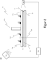
- FIG. 2 This problem overcomes the present invention as shown in FIG. 2 is shown.
- a first fiber composite joining partner 11 With a second fiber composite joining partner 12 by means of an adhesive material or an adhesive bond 13, which is introduced a joint gap 14, or connect.
- the second fiber composite joining partner 12 is completely crosslinked and cured, while the first fiber composite joining partner 11 is partially crosslinked.
- a complete networking here means at least a degree of crosslinking of more than 95%, but preferably more than 99%, while a partial crosslinking means at least 60% (preferably 65%) and particularly preferably 70% degree of crosslinking.
- a joined fiber composite component 10 is formed, which is connected to a forming device 110 on the legs 11a and 11b of the first fiber composite joining partner. Furthermore, a sensor system 120 is provided, which uses ultrasound signals to determine the degree of crosslinking of the matrix material of the at least first fiber composite joining partner 11, from which the glass transition temperature can then be determined.
- a tempering device 130 is provided, which is designed for tempering the fiber composite component 10. This may be, for example, an oven integrated into, for example, an autoclave.
- a gap detection device 140 is schematically provided, which is designed to detect the joint gap 14 of the adhesive bond 13, in particular with regard to the wall thickness or with respect to the gap thickness of the joint gap 14, so as to achieve a uniform course of the wall thickness of the joint gap 14.
- the deformation device 110, the sensor system 120, the tempering device 130 and the gap detection device 140 are connected to an evaluation and control unit so as to be able to actively intervene in the joining process. From the sensor system 120, the degree of crosslinking of the matrix material of the first fiber composite joining partner 11 is determined, so that based on the current glass transition temperature of the matrix material of the first fiber composite joining partner 11 is determined. Based on this, the tempering device 130 is then actuated in order to temper the fiber composite component 10, in particular the first fiber composite joining partner 11, in such a way that the temperature is in the range around that determined Glass transition temperature is.
- the temperature is regulated by the tempering device 130 in such a way that this condition is fulfilled with respect to the glass transition temperatures which are continuously determined continuously again and again.
- the first fiber composite joining partner 11 is plastically deformable.
- the deformation device 110 is then actuated so as to plastically deform the first fiber composite joining partner 11 such that a predetermined wall thickness and possibly uniformity of the joint gap 14 is set by the plastic deformation of the first fiber composite joining partner 11 , In this way, it can be achieved that the wall thickness always remains uniform throughout the entire joining and curing process, whereby the parameters of the wall thickness of the joint gap 14 during the annealing process can be influenced with the aid of such a device.
- the fiber composite component 10 may be introduced into a vacuum device, for example a film bag, and then the entire component 10 to be evacuated, as a result of which a vacuum is established in the film bag.
- a vacuum device for example a film bag
- the ambient pressure would now cause a force on the legs 11 a, 11 b is exercised, whereby also a uniform wall thickness of the joint gap 14 can be adjusted when the first fiber composite joining partner 11 tempered in a range around its current glass transition temperature becomes.
- a forming device 110 as in FIG. 2 it does not need to be shown here.
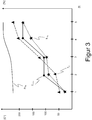
- FIG. 3 shows a diagram illustrating the correlation between the temporal progress of the annealing process (X-axis) and the temperature and the degree of cure (Y-axis).
- the labeled T furnace chart the course characterizes the temperature profile of the five process steps T 1 to T 5 for controlling the temperature of the fiber composite component. As you can see, it starts Temperature curve at time T 1 at about 25 ° C and then increases up to process step T 2 to about 100 ° C. Until the process step T 3 , it then remains at about 100 ° C, and then rise to the process step T 4 to the final temperature of 175 ° C.
- the temperature curve marked T Füg is an estimate of the component temperature of the first fiber composite joining partner. This temperature profile feeds on the temperature profile T furnace of the tempering device and remains due to the inertia of the entire system behind the temperature curve T furnace of the tempering back.
- the temperature curve T G shows the change in the glass transition temperature of the first fiber composite joining partner.
- the glass transition temperature correlates with the degree of crosslinking, which is indicated by the curve P Füg (P stands for polymerization) of the first joining partner.
- P Füg P stands for polymerization
- the plastic deformability begins between the first T 1 and second T 2 process step and ends at the latest in the third process step, in which due to the further crosslinking, the glass transition temperature is again above the component temperature and the component temperature, the glass transition temperature and no longer approximates that a plastic Deformability is achieved.
Landscapes
- Engineering & Computer Science (AREA)
- Mechanical Engineering (AREA)
- Physics & Mathematics (AREA)
- Thermal Sciences (AREA)
- Chemical & Material Sciences (AREA)
- Chemical Kinetics & Catalysis (AREA)
- General Chemical & Material Sciences (AREA)
- Lining Or Joining Of Plastics Or The Like (AREA)
Abstract
- Bereitstellen der Faserverbund-Fügepartner, wobei bei zumindest dem ersten Faserverbund-Fügepartner (11) das Matrixmaterial des Faserverbundwerkstoff teilvernetzt ist,
- Einbringen des Klebwerkstoffes (13) in einen Fügespalt (14) zwischen den Faserverbund-Fügepartnern, und
- Tempern des aus den Faserverbund-Fügepartnern und dem Klebwerkstoff (13) gebildeten Faserverbundbauteils durch Temperierung mittels einer Temperiereinrichtung (130), um zumindest das Matrixmaterial des ersten Faserverbund-Fügepartners (11) und den Klebwerkstoff (13) vollständig zu vernetzen,
wobei während des Temperprozesses
- der Vernetzungsgrad des Matrixmaterials zumindest des ersten Faserverbund-Fügepartner (11) mittels eines Sensorsystems (120) erfasst und aus dem momentanen Vernetzungsgrad die aktuelle Glasübergangstemperatur des Matrixmaterials bestimmt wird, und
- für einen ersten Zeitraum das gefügte Faserverbundbauteil (10) in einem Bereich um die aktuelle Glasübergangstemperatur derart temperiert wird, dass der erste Faserverbund-Fügepartner (11) plastisch verformbar wird,
- wobei innerhalb des ersten Zeitraumes der erste Faserverbund-Fügepartner (11) zur Einstellung einer vorgegebenen Stärke und ggf. Gleichmäßigkeit des Fügespaltes (14) plastisch verformt wird.
Description
- Die Erfindung betrifft ein Verfahren zum Fügen eines ersten Faserverbund-Fügepartners an wenigstens einen zweiten Faserverbund-Fügepartner mittels einer Klebverbindung, wobei der erste und der zweite Faserverbund-Fügepartner einen Faserverbundwerkstoff aufweisen oder aus einem solchen bestehen und die Klebverbindung durch einen unter Temperaturbeaufschlagung vernetzbaren bzw. aushärtbaren Klebwerkstoff gebildet wird.
- Der Einsatz von Faserverbundwerkstoffen vereint die Eigenschaft einer hohen Festigkeit und Steifigkeit eines Bauteils mit einem sehr niedrigen Gewicht. Der Einsatz derartiger Werkstoffe ist daher unter dem Aspekt des Leichtbaus besonders vorteilhaft. Allerdings ist die hohe gewichtsspezifische Festigkeit und Steifigkeit des Werkstoffes richtungsabhängig, sodass bei Bauteilen, die eine hohe Festigkeit und Steifigkeit in mehrere verschiedene Richtungen aufweisen müssen, komplexe Strukturen entstehen, die nicht selten aus mehreren Einzelteilen zusammengesetzt werden müssen.
- Faserverbundwerkstoffe weisen dabei in der Regel zwei verschiedene Komponenten auf: a) den Faserwerkstoff bzw. das Fasermaterial und b) das Matrixmaterial.
- Das Fasermaterial bzw. der Faserwerkstoff wird dabei von dem Matrixmaterial umschlossen und bildet so beim Aushärten (es wird auch von Vernetzung bzw. Polymerisation gesprochen) des Matrixmaterials, bei dem das Matrixmaterial seine spezifische Festigkeit und Steifigkeit erhält, eine integrale Einheit. Als Fasermaterial kommen dabei insbesondere Kohlenstofffasern und Glasfasern in Betracht.
- Die verwendeten Matrixmaterialien sind in der Regel Kunststoffe, wie bspw. Epoxidharz, oder allgemeiner thermoplastische oder duroplastische Kunststoffe. Durch Temperierung dieser Matrixmaterialien wird eine chemische Vernetzungsreaktion beschleunigt, die dazu führt, dass das Matrixmaterial polymerisiert und somit aushärtet und die darin eingebetteten Fasern des Fasermaterials in die entsprechende Form zwingt. Während duroplastische Kunststoffe nach dem Aushärten ihre feste Form auch unter Wärmeeintrag behalten, können thermoplastische Kunststoffe bei Überschreiten einer vorgegebenen Temperatur wieder aufgeschmolzen werden.
- Um die bereits angesprochenen komplexen Bauteilstrukturen zu erreichen, werden in der Praxis nicht selten mehrere verschiedene Elemente zu einem großen Bauteil zusammengefügt. Kraft- bzw. formschlüssige Verbindungen, wie bspw. Verschraubungen oder das Vernieten von Bauteilen, ist je nach Einsatzzweck des herzustellenden Faserverbundbauteils nur bedingt einsetzbar, da eine derartige Fügetechnik immer einhergeht mit einer lokalen Zerstörung der Fasern des in das Matrixmaterial eingebetteten Fasermaterials, was dazu führt, dass die Steifigkeit und Festigkeit des Faserverbundbauteils nicht mehr den vorgegebenen Qualitätsbedingungen entspricht.
- Des Weiteren weisen Faserverbundbauteile in der Regel fertigungsbedingte Formabweichungen auf, was zu Problemen bei der Montage dieser Bauteile zu einer übergeordneten Bauteilgruppe führen kann, insbesondere dann, wenn form- bzw. kraftschlüssige Verbindungstechniken eingesetzt werden. So ist aus der
DE 10 2014 100 780 A1 bspw. ein Faserverbundmontageverfahren bekannt, bei dem das fertig hergestellte Faserverbundbauteil in einer Verformungseinrichtung eingespannt und so verformt wird, dass es mit dem zweiten Fügepartner im Fügebereich in Deckung gebracht werden kann. Allerdings wird hierbei in Kauf genommen, dass die Bauteile unter einer gewissen Krafteinwirkung und Spannung miteinander verbunden sind. - Eine weitere Fügetechnik bei der Herstellung komplexer Faserverbundbauteile ist das Verkleben bzw. die Verklebung von Faserverbundkomponenten. Aus der Praxis sind hierbei im Wesentlichen drei verschiedene klebende Fügeverfahren bekannt. Bei dem sogenannten Co-Curing werden zwei vollständig unvernetzte und damit geometrisch flexible Faserverbund-Fügepartner mittels einer Klebschicht verbunden und anschließend gemeinsam ausgehärtet. Nachteil hierbei ist, dass beide Fügepartner geometrisch sehr instabil sind, sodass für den gesamten Prozess wenigstens zwei formgebende Werkzeuge notwendig sind. Zusätzlich wird eine Vorrichtung benötigt, die diese beiden formgebenden Werkzeuge zueinander ausrichtet. Eine Qualitätskontrolle kann in Bezug auf die Eigenschaften der Einzelkomponenten erst nach Prozessende erfolgen, d.h. im Fehlerfall müssen beide Komponenten ersetzt werden.
- Ein weiteres Fügeverfahren stellt das sogenannte Co-Bonding dar, bei dem einer der Fügepartner vollständig unvernetzt ist, während der andere Fügepartner vollständig vernetzt und somit ausgehärtet ist. Für den flexiblen, unvernetzten Fügepartner ist dabei in der Regel auch ein Formwerkzeug notwendig, wobei auch dieses mit Hilfe einer Positioniereinrichtung relativ zum ausgehärteten Fügepartner positioniert werden muss. Eine Qualitätskontrolle am unvernetzten Fügepartner kann erst nach dem Fügeprozess erfolgen.
- Bei dem dritten Fügeverfahren, dem sogenannten Secondary Bonding, werden zwei vollständig vernetzte Bauteile, d.h. zwei starre, ausgehärtete Bauteile, über eine Klebverbindung miteinander verbunden, wobei der Nachteil hierbei besteht, dass die Klebverbindung weniger leistungsfähig ist, da sie kein Polymernetzwerk zu den Fügepartnern ausbildet. Der entscheidende Nachteil ist jedoch, dass im Fügeprozess keine geometrischen Abweichungen der Fügepartner ausgeglichen werden können, die sich direkt auf eine ungleichmäßige Wandstärke der Klebschicht auswirken. Mit anderen Worten, ein wesentliches Qualitätskriterium für eine tragfähige Klebverbindung, nämlich die Einstellung einer vorgegebenen bzw. vordefinierten Wandstärke der Klebverbindung, kann während des Fügeprozesses nicht beeinflusst werden.
- Bei der Bewertung der mechanischen Leistungsfähigkeit von Verklebungen von Faserverbundkomponenten spielt die Wandstärke des Klebespaltes jedoch eine entscheidende Rolle. Die Einstellung dieses Klebespaltes während des Prozesses auf eine gleichmäßige, vorher definierte Wandstärke hat sich insbesondere bei der Verklebung toleranzbehafteter Faserverbundkomponenten als problematisch und sehr aufwendig herausgestellt.
- Es ist daher Aufgabe der vorliegenden Erfindung, ein verbessertes Verfahren zum Fügen zweier Faserverbund-Fügepartner anzugeben, mit dem die Eigenschaften des Klebespaltes hinsichtlich der Wandstärke während des Verklebens der beiden Fügepartner beeinflusst werden kann.
- Die Aufgabe wird mit dem Verfahren gemäß Anspruch 1 erfindungsgemäß gelöst.
- Gattungsgemäß beansprucht Patentanspruch 1 ein Verfahren zum Fügen eines ersten Faserverbund-Fügepartners an wenigstens einen zweiten Faserverbund-Fügepartner mittels einer Klebverbindung, wobei der erste und der zweite Faserverbund-Fügepartner einen Faserverbundwerkstoff aufweisen oder aus einem solchen bestehen und die Klebverbindung durch einen unter Temperaturbeaufschlagung vernetzbaren Klebwerkstoff gebildet wird.
- Dabei wird zumindest der erste Faserverbund-Fügepartner so bereitgestellt, dass das Matrixmaterial des ersten Faserverbund-Fügepartners teilvernetzt ist. Teilvernetzt meint hierbei, dass der Vernetzungsgrad der Vernetzungsreaktion über 50 % liegt und die Vernetzungsreaktion somit schon teilweise begonnen hat. Der zweite Faserverbund-Fügepartner wird dabei vorteilhafterweise so bereitgestellt, dass das Matrixmaterial des zweiten Faserverbund-Fügepartners bereits ausgehärtet ist, d.h. vollständig vernetzt ist.
- Anschließend wird zwischen den beiden Faserverbund-Fügepartnern in einem Fügespalt ein Klebwerkstoff eingebracht, sodass die beiden Faserverbund-Fügepartner über den in den Fügespalt eingebrachten Klebwerkstoff klebend miteinander verbunden werden können. Anschließend wird dann das aus den Faserverbund-Fügepartnern und dem Klebwerkstoff gebildete Faserverbundbauteil durch Temperierung mittels einer Temperiereinrichtung getempert, um zumindest das Matrixmaterial des ersten Faserverbund-Fügepartners und den Klebwerkstoff vollständig zu vernetzen.
- Erfindungsgemäß ist dabei vorgesehen, dass während des Temperprozesses der Vernetzungsgrad des Matrixmaterials zumindest des ersten Faserverbund-Fügepartners mittels eines Sensorsystems erfasst und aus dem momentanen Vernetzungsgrad die aktuelle Glasübergangstemperatur des Matrixmaterials bestimmt wird und für einen ersten Zeitraum das gefügte Faserverbundbauteil in einem Bereich um die aktuelle Glasübertragungstemperatur derart temperiert wird, dass der erste Faserverbund-Fügepartner elastisch verformbar ist. Innerhalb dieses ersten Zeitraumes wird dann der erste Faserverbund-Fügepartner zur Einstellung einer vorgegebenen Stärke und gegebenenfalls Gleichmäßigkeit des Fügespaltes plastisch verformt, sodass die Eigenschaft des Fügespaltes hinsichtlich der Wandstärke des Fügespaltes während des Verklebens der beiden Fügepartner beeinflusst werden kann.
- Dabei wurde erkannt, dass bei der Verwendung eines teilvernetzten Fügepartners eine Temperierung um den Bereich der Glasübergangstemperatur eine plastische Verformbarkeit des Faserverbundbauteils während des Fügeverfahrens möglich ist, mit der dann die vorgegebene Stärke und gegebenenfalls Gleichmäßigkeit des Fügespaltes eingestellt werden kann.
- Unter dem Tempern des Faserverbundbauteils im Sinne der vorliegenden Erfindung wird insbesondere verstanden, dass das Faserverbundbauteil mittels einer Temperiereinrichtung über einen vorgegebenen oder vorgebbaren Zeitraum hinweg temperiert wird, wobei die Temperaturkurve über den Temperierzeitraum hinweg vorgegeben, vorgebbar und/oder regelbar ist.
- Die Glasübergangstemperatur ist dabei die Temperatur, bei der das Matrixmaterial des Faserverbundwerkstoffes von einem im Wesentlichen festen Zustand, bei dem eine plastische Verformbarkeit des Fügepartners nicht gegeben ist, in einen im Wesentlichen schmelzartigen oder forminstabilen Zustand, bei dem eine plastische Verformbarkeit des Fügepartners gegeben ist, wechselt. Die Glasübergangstemperatur bezeichnet hierbei jedoch keinen Phasenübergang und ist insbesondere abhängig von der Temperatur des Bauteils und dem Vernetzungsgrad des Matrixmaterials. Daher ist es ganz besonders vorteilhaft, wenn sowohl die Ist-Temperatur als auch der Vernetzungsgrad mit Hilfe von Sensoren, für die Temperatur ein Thermosensor und für den Vernetzungsgrad bspw. dielektrische Sensoren oder Ultraschallsensoren, ermittelt wird, um so die Glasübertragungstemperatur des Matrixmaterials aus der Ist-Temperatur und dem Vernetzungsgrad ableiten zu können. Denn die Glasübergangstemperatur korreliert gerade bei Matrixmaterialien von Faserverbundwerkstoffen mehr oder weniger direkt mit dem Vernetzungsgrad des Matrixmaterials.
- Darüber hinaus ist bei einem zu großen Überschreiten der Glasübergangstemperatur die Gefahr groß, dass aufgrund von Überhitzung des Matrixmaterials die Polymerketten des Matrixmaterials Schaden nehmen und so das gesamte Bauteil fehlerbehaftet ist. Daher ist erfindungsgemäß vorgesehen, dass in dem ersten Zeitraum das gefügte Faserverbundbauteil in einem Bereich um die aktuelle Glasübertragungstemperatur getempert wird, wobei dieser Bereich meint, dass die Temperatur des Temperprozesses dicht unter oder dicht über der aktuellen Glasübergangstemperatur liegt. Dicht über der aktuellen Glasübergangstemperatur meint hier vorzugsweise einen Bereich von maximal 10 Kelvin oberhalb der Glasübergangstemperatur, besonders vorzugsweise maximal 5 Kelvin über der Glasübergangstemperatur. Dicht unterhalb der Glasübertragungstemperatur meint hierbei, dass das Faserverbundbauteil so mit Hilfe des Temperprozesses temperiert wird, dass eine plastische Verformbarkeit gegeben ist, was in der Regel in einem Bereich von 15 Kelvin unter der aktuellen Glasübergangstemperatur gegeben ist, vorzugsweise 10 Kelvin unter der Glasübergangstemperatur, und besonders vorzugsweise 5 Kelvin unter der Glasübergangstemperatur.
- Ein weiterer Vorteil der Erfindung ist, dass der Klebwerkstoff mit zumindest dem teilvernetzten Fügepartner noch ein Polymernetzwerk ausbilden kann, was die Festigkeit der Klebverbindung verbessert.
- Am Vorteilhaftesten ist es, wenn das Bauteil so temperiert wird, dass die Glasübergangstemperatur möglichst dicht angenähert wird, ohne diese jedoch zu überschreiten, wodurch der Fügepartner im teilvernetzten Zustand plastisch verformbar ist, ohne jedoch seine Eigenstabilität gänzlich zu verlieren. Ein derartiger Regelungsprozess während des Temperprozesses lässt sich durch die Ermittlung des Vernetzungsgrades mit Hilfe von Sensoren, der aktuellen Ist-Temperatur und einer entsprechenden Steuerung der Temperiereinrichtung in Abhängigkeit des Vernetzungsgrades und der Ist-Temperatur realisieren.
- Eine weiterer Vorteil des erfindungsgemäßen Verfahrens besteht darin, dass neben der Beeinflussung der Wandstärke des Klebespaltes auch ein Polymernetzwerk des Klebwerkstoffes mit dem anfänglich teilvernetzten Fügepartner hergestellt wird, wodurch die Klebverbindung stabiler und weniger anfällig für Beschädigungen wird.
- In einer vorteilhaften Ausführungsform wird der erste Faserverbund-Fügepartner, dessen Matrixmaterial anfänglich teilvernetzt war, mit einer Verformungseinrichtung verbunden, wobei während des Temperprozesses innerhalb des ersten Zeitraumes mittels einer Spalterfassungsvorrichtung die Stärke des Fügespaltes erfasst und der erste Fügepartner mittels der verbundenen Verformungseinrichtung derart plastisch verformt wird, dass eine vorgegebene Stärke und ggf. Gleichmäßigkeit des Fügespaltes durch ein plastisches Verformen des Fügepartners mittels der Verformungseinrichtung eingestellt wird. Hierdurch wird es möglich, aktiv auf den Prozessparameter der Wandstärke des Klebespaltes einzuwirken und diesen während des Temperprozesses innerhalb des ersten Zeitraumes entsprechend einzustellen.
- In einer vorteilhaften alternativen Ausführungsform wird auf eine aktive Verformungseinrichtung verzichtet und das gefügte Faserverbundbauteil in eine Vakuumeinrichtung, beispielsweise ein Foliensack, eingebracht und mittels einer Drucksenke evakuiert. In der Vakuumeinrichtung wird somit ein Vakuum bzw. Feinvakuum eingestellt, wodurch aufgrund des Umgebungsdruckes oder eines Autoklavdruckes, sofern das Bauteil in einen Autoklaven eingefahren wird, ein entsprechender Druck von außen auf das Bauteil wirkt. Das gefügte Faserverbundbauteil wird dabei so in die Vakuumeinrichtung eingebracht, dass bei Evakuierung des Faserverbundbauteils ein Umgebungsdruck auf den ersten Faserverbund-Fügepartner wirkt. Der Umgebungsdruck kann hierbei auch ein Autoklavdruck sein. Aufgrund der Tatsache, dass nunmehr auf den ersten Fügepartner ein Umgebungsdruck wirkt, kann ein automatisches Einstellen des Klebespaltes realisiert werden, da durch den erfindungsgemäßen Temperprozess der Fügepartner innerhalb des ersten Zeitraumes plastisch verformbar ist und der von außen wirkende Umgebungsdruck dazu führt, dass der erste Fügepartner aufgrund des Umgebungsdruckes plastisch verformt wird und sich somit zumindest ein gleichmäßiger Fügespalt einstellt.
- Vorteilhafterweise wird zumindest in einem Randbereich des Fügespaltes ein Stützgewebe eingebracht, so dass bei einer Verformung des ersten Fügepartners die Wandstärke des Klebespaltes eingestellt und verhindert werden kann, so dass der Klebwerkstoff an der Seite des Klebespaltes entweichen kann.
- Vorteilhafterweise wird während des Temperprozesses innerhalb des ersten Zeitraumes das gefügte Faserverbundbauteil weiterhin so temperiert, dass neben dem ersten Faserverbund-Fügepartner auch der Klebwerkstoff in einem Bereich um die Glasübergangstemperatur des Klebwerkstoffes getempert wird und der Klebwerkstoff so ebenfalls plastisch verformbar ist. Dies hat den Vorteil, dass bei einer plastischen Verformung des ersten Fügepartners auch der Klebwerkstoff mit verformt wird, wodurch sich eine gleichmäßige Wandstärke des Klebespaltes einstellen lässt.
- In einer weiteren sehr vorteilhaften Ausführungsform schließt sich an den ersten Zeitraum ein zweiter Zeitraum des Temperprozesses an, innerhalb dessen das gefügte Faserverbundbauteil derart temperiert wird, dass die Glasübergangstemperatur des Matrixmaterials des ersten Faserverbund-Fügepartners über dem Temperatur des Temperprozesses liegt, so dass der erste Faserverbund- Fügepartner nicht mehr plastisch verformbar ist. Insbesondere wird das Faserverbundbauteil so temperiert, dass die Temperatur des Faserverbundbauteils außerhalb des Bereiches nahe der Glasübergangstemperatur, innerhalb dessen der Fügepartner plastisch verformbar ist, aber unterhalb der Glasübergangstemperatur. Dies hat den Vorteil, dass nach einer plastischen Verformung des ersten Fügepartners und einer entsprechenden Einstellung der Wandstärke des Klebespaltes dann der erste Fügepartner sich nicht mehr plastisch verformen lässt, wodurch die Form und Geometrie des ersten Fügepartners für den weiteren Temperprozess fixiert wird und sich somit nicht mehr negativ auf die Gleichmäßigkeit des Klebespaltes auswirken kann.
- Dies gilt auch für den Klebwerkstoff, so dass es auch hier vorteilhaft ist, wenn sich an den ersten Zeitraum ein zweiter Zeitraum des Temperprozesses anschließt, innerhalb dessen das gefügte Faserverbundbauteil derart temperiert wird, dass die Glasübergangstemperatur des Klebwerkstoffes über der Temperatur des Temperprozesses liegt, so dass sich der Klebwerkstoff nicht mehr plastisch verformen lässt. Die Temperatur des Faserverbundbauteils wird somit so geregelt, dass die Temperatur außerhalb des Bereiches nahe der Glasübergangstemperatur liegt, aber unterhalb dieser Glasübergangstemperatur, so dass sich der Klebwerkstoff nicht mehr plastisch verformen lässt. In Kombination mit dem vorhergehend Gesagten wird somit eine anfängliche Verformbarkeit sowohl des ersten Fügepartners als auch des Klebwerkstoffes realisiert, um so einen gleichmäßigen Fügespalt einzustellen, während dann für den vorzugsweise restlichen Zeitraum bis zum Ende des Temperprozesses dann sowohl der erste Fügepartner als auch der Klebwerkstoff hinsichtlich ihrer Form und Geometrie fixiert und somit unveränderbar werden. Spätere Formabweichungen, welche die Qualität des Bauteils negativ beeinflussen, können somit verhindert werden.
- Der anfängliche Vernetzungsgrad des teilvernetzten Matrixmaterials des ersten Faserverbund- Fügegrads liegt vorzugsweise zwischen 60 % und 80 %, besonders vorzugsweise zwischen 65 % und 75 %. Es hat sich dabei als vorteilhaft herausgestellt, wenn der anfängliche Vernetzungsgrad des teilvernetzten Matrixmaterials des ersten Fügepartners bei ca. 70 % liegt.
- In einer weiteren vorteilhaften Ausführungsform enthält der Klebwerkstoff ein Epoxidharzmaterial bzw. eine Epoxidharzmatrix oder besteht aus einer solchen. Des Weiteren ist auch vorteilhaft, wenn das Matrixmaterial des Faserverbund-Fügepartners eine Epoxidharzmatrix enthält oder aus dieser besteht. Ganz besonders vorteilhaft ist es, wenn sowohl für den Klebwerkstoff als auch für das Matrixmaterial des ersten Fügepartners jeweils ein Material verwendet wird, das entweder gleich ist oder hinsichtlich seiner Vernetzungseigenschaften (Temperatur/Glasübergangstemperaturkurve) im Wesentlichen gleich sind oder zumindest annährend gleiche Eigenschaften aufweisen.
- Die Erfindung wird anhand der beigefügten Figuren beispielhaft näher erläutert. Es zeigen:
- Figur 1 -
- Schematische Darstellung eines nicht-korrigierten Fügeergebnisses;
- Figur 2 -
- Schematische Darstellung des Fügens zweier Fügepartner gemäß der vorliegenden Erfindung;
- Figur 3 -
- Diagramm eines Beispielsprozesses.
-
Figur 1 zeigt das Fügen zweier Fügepartner, wobei ein erster Faserverbund-Fügepartner 1 mit einen zweiten Faserverbund-Fügepartner 2 mittels einer Klebverbindung 3 in einem Fügespalt 4 verklebt werden soll. - In der Darstellung der
Figur 1 ist sowohl der Fügepartner 1 als auch der Fügepartner 2 vollständig vernetzt und somit starre Bauteile, wobei der Fügepartner 1 ein T-Profil darstellt, das auf einen flächigen Fügepartner 2 mithilfe der Klebverbindung 3 aufgeklebt werden soll. - Aufgrund einer prozessinduzierten Verformung setzt der Fügepartner 1 einen nicht rechtwinkligen Verlauf zwischen den Schenkeln 1a, 1 b des T-Profils und dem vertikalen Stringer 1 c, so dass die beiden Schenkel 1a und 1 b unter einem Winkel < 180° verlaufen. Dies führt dazu, dass der Fügespalt 4 nicht gleichmäßig ausgebildet ist, was zu Qualitätsbeeinträchtigungen führt.
- Dieses Problem überwindet die vorliegende Erfindung, wie dies in
Figur 2 dargestellt ist. Mithilfe der dort dargestellten Vorrichtung 100 wird es möglich, einen ersten Faserverbund-Fügepartner 11 mit einem zweiten Faserverbund-Fügepartner 12 mittels eines Klebwerkstoffes bzw. einer Klebverbindung 13, die einen Fügespalt 14 eingebracht wird, zu verkleben bzw. zu verbinden. Der zweite Faserverbund-Fügepartner 12 ist dabei vollständig vernetzt und ausgehärtet, während der erste Faserverbund-Fügepartner 11 teilvernetzt ist. Eine vollständige Vernetzung meint hierbei zumindest einen Vernetzungsgrad von mehr als 95 %, aber vorzugsweise mehr als 99 %, während eine Teilvernetzung mindestens 60 % (vorzugsweise 65 %) und besonders vorzugsweise 70 % Vernetzungsgrad meint. - Aus dem ersten Faserverbund-Fügepartner 11 und dem zweiten Faserverbund-Fügepartner 12 sowie der dazwischenliegenden Klebverbindung bzw. des Klebwerkstoffes 13 wird somit ein gefügtes Faserverbundbauteil 10 gebildet, das mit einer Umformeinrichtung 110 an den Schenkeln 11a und 11b des ersten Faserverbund-Fügepartners verbunden wird. Des Weiteren ist ein Sensorsystem 120 vorgesehen, das mithilfe von Ultraschallsignalen den Vernetzungsgrad des Matrixmaterials des zumindest ersten Faserverbund-Fügepartners 11 ermittelt, aus dem dann die Glasübergangstemperatur ermittelbar wird.
- Des Weiteren ist eine Temperiereinrichtung 130 vorgesehen, die zum Temperieren des Faserverbundbauteils 10 ausgebildet ist. Hierbei kann es sich beispielsweise um einen Ofen, integriert beispielsweise in einen Autoklaven, handeln.
- Schließlich ist schematisch angedeutet noch eine Spalterfassungseinrichtung 140 vorgesehen, die ausgebildet ist, den Fügespalt 14 der Klebverbindung 13 zu erfassen, insbesondere hinsichtlich der Wandstärke bzw. hinsichtlich der Spaltstärke des Fügespaltes 14, um so einen gleichmäßigen Verlauf der Wandstärke des Fügespaltes 14 zu erreichen.
- Die Verformungseinrichtung 110, das Sensorsystem 120, die Temperiereinrichtung 130 sowie die Spalterfassungseinrichtung 140 sind mit einer Auswerte- und Steuereinheit verbunden, um so aktiv in den Fügeprozess eingreifen zu können. Aus dem Sensorsystem 120 wird der Vernetzungsgrad des Matrixmaterials des ersten Faserverbund-Fügepartners 11 ermittelt, so dass basierend darauf die aktuelle Glasübergangstemperatur des Matrixmaterials des ersten Faserverbund-Fügepartners 11 ermittelt wird. Basierend darauf wird sodann die Temperiereinrichtung 130 angesteuert, um das Faserverbundbauteil 10, insbesondere den ersten Faserverbund-Fügepartner 11, derart zu temperieren, dass die Temperatur im Bereich um die ermittelte Glasübergangstemperatur liegt. Für einen gewissen ersten Zeitraum des Temperprozesses wird dabei die Temperatur durch die Temperiereinrichtung 130 so geregelt, dass diese Bedingung bezüglich der aktuell immer wieder kontinuierlich ermittelten Glasübergangstemperaturen erfüllt ist. In diesem Bereich ist der erste Faserverbund-Fügepartner 11 plastisch verformbar.
- Basierend auf den Ergebnissens der Spalterfassungseinrichtung 140 wird sodann die Verformungseinrichtung 110 angesteuert, um so den ersten Faserverbund-Fügepartner 11 plastisch so zu verformen, dass eine vorgegebene Wandstärke und ggf. Gleichmäßigkeit des Fügespaltes 14 durch die plastische Verformung des ersten Faserverbund-Fügepartners 11 eingestellt wird. Hierdurch kann erreicht werden, dass die Wandstärke immer gleichmäßig während des gesamten Füge- und Aushärteprozesses bestehen bleibt, wodurch mithilfe einer derartigen Vorrichtung auf den Parameter der Wandstärke des Fügespaltes 14 während des Temperprozesses Einfluss genommen werden kann.
- Alternativ ist es denkbar, dass das Faserverbundbauteil 10 in eine Vakuumeinrichtung, beispielsweise einen Foliensack, eingebracht wird und anschließend das gesamte Bauteil 10 evakuiert wird, wodurch sich in dem Foliensack ein Vakuum einstellt. Bei einem Faserverbundbauteil, wie in
Figur 2 dargestellt, würde nun der Umgebungsdruck dazu führen, dass eine Kraft auf die Schenkel 11 a, 11 b ausgeübt wird, wodurch ebenfalls eine gleichmäßige Wandstärke des Fügespaltes 14 eingestellt werden kann, wenn der erste Faserverbund-Fügepartner 11 in einen Bereich um seine aktuelle Glasübergangstemperatur temperiert wird. Hierdurch ergibt sich der Vorteil, dass eine Gleichmäßigkeit des Fügespaltes ohne äußere Einflüsse allein basierend auf dem Umgebungsdruck realisiert werden kann. Einer Umformeinrichtung 110, wie inFigur 2 dargestellt, bedarf es da nicht. -
Figur 3 zeigt schließlich ein Diagramm zur Veranschaulichung der Korrelation zwischen dem zeitlichen Fortschritt des Temperprozesses (X-Achse) und der Temperatur sowie des Aushärtungsgrades (Y-Achse). Der mit TOfen bezeichnete Diagrammverlauf kennzeichnet dabei den Temperaturverlauf über die fünf Prozessschritte T1 bis T5 zur Temperierung des Faserverbundbauteils. Wie zu erkennen ist, beginnt die Temperaturkurve beim Zeitpunkt T1 bei etwa 25° C und steigt dann bis zum Prozessschritt T2 auf etwa 100° C an. Bis zum Prozessschritt T3 verbleibt sie dann auf etwa 100° C, um dann bis zum Prozessschritt T4 auf die Endtemperatur von 175° C anzusteigen. - Die mit TFüg gekennzeichnete Temperaturkurve ist dabei eine Abschätzung der Bauteiltemperatur des ersten Faserverbund-Fügepartners. Dieser Temperaturverlauf nährt sich dem Temperaturverlauf TOfen der Temperiereinrichtung an und bleibt aufgrund der Trägheit des Gesamtsystems hinter der Temperaturkurve TOfen der Temperiereinrichtung zurück.
- Die Temperaturkurve TG zeigt schließlich die Veränderung der Glasübergangstemperatur des ersten Faserverbund-Fügepartners. Die Glasübergangstemperatur korreliert dabei mit dem Vernetzungsgrad, der durch den Verlauf PFüg (P steht für Polymerisation) des ersten Fügepartners angezeigt wird. Anfänglich, d.h. im Prozessschritt T1 befindet sich die Glasübergangstemperatur bei ca. 50° C und liegt oberhalb der Temperatur des ersten Fügepartners. Durch Temperierung des ersten Fügepartners schreitet die Vernetzungsreaktion weiter an, wodurch die Glasübergangstemperatur weiter ansteigt und im Prozessschritt T2 bei ca. 75° C liegt. Zu diesem Zeitpunkt liegt die Temperatur des Faserverbundbauteils leicht oberhalb der Glasübergangstemperatur, wodurch zum Prozessschritt T2 der erste Fügepartner plastisch verformbar ist. Die plastische Verformbarkeit beginnt dabei zwischen dem ersten T1 und zweiten T2 Prozessschritt und endet spätestens bei dem dritten Prozessschritt, bei dem aufgrund der weiterführenden Vernetzung die Glasübergangstemperatur wieder über der Bauteiltemperatur liegt und die Bauteiltemperatur die Glasübergangstemperatur auch nicht mehr sowie annähert, dass eine plastische Verformbarkeit erreicht wird.
-
- 1
- - starrer erster Fügepartner
- 2
- - starrer zweiter Fügepartner
- 3
- - Klebwerkstoff/Klebverbindung
- 4
- - Fügespalt
- 10
- - gefügtes Faserverbundbauteil
- 11
- - teilvernetzter erster Fügepartner
- 12
- - vollvernetzter zweiter Fügepartner
- 13
- - Klebwerkstoff/Klebverbindung
- 14
- - Fügespalt
- 100
- - Vorrichtung
- 110
- - Verformungseinrichtung
- 120
- - Sensorsystem
- 130
- - Temperiereinrichtung
- 140
- - Spalterfassungseinrichtung
- 150
- - Auswerte- und Steuereinheit
- TOfen
- - Temperaturverlauf Temperiereinrichtung
- TFüg
- - Temperaturverlauf Fügepartner
- TG
- - Temperaturverlauf Glasübergangstemperatur
- PFüg
- - Verlauf des Vernetzungsgrades
Claims (11)
- Verfahren zum Fügen eines ersten Faserverbund-Fügepartner (1) an wenigstens einen zweiten Faserverbund-Fügepartner (2) mittels einer Klebverbindung (3), wobei der erste und der zweite Faserverbund-Fügepartner einen Faserverbundwerkstoff aufweisen oder aus einem solchen bestehen und die Klebverbindung (3) durch einen unter Temperaturbeaufschlagung vernetzbaren Klebwerkstoff (3) gebildet wird, mit den Schritten:- Bereitstellen der Faserverbund-Fügepartner, wobei bei zumindest dem ersten Faserverbund-Fügepartner (1) das Matrixmaterial des Faserverbundwerkstoff teilvernetzt ist,- Einbringen des Klebwerkstoffes (3) in einen Fügespalt (4) zwischen den Faserverbund-Fügepartnern, und- Tempern des aus den Faserverbund-Fügepartnern und dem Klebwerkstoff (3) gebildeten Faserverbundbauteils durch Temperierung mittels einer Temperiereinrichtung (130), um zumindest das Matrixmaterial des ersten Faserverbund-Fügepartners (1) und den Klebwerkstoff (3) vollständig zu vernetzen,dadurch gekennzeichnet, dass während des Temperprozesses- der Vernetzungsgrad des Matrixmaterials zumindest des ersten Faserverbund-Fügepartner (1) mittels eines Sensorsystems (120) erfasst und aus dem momentanen Vernetzungsgrad die aktuelle Glasübergangstemperatur des Matrixmaterials bestimmt wird, und- für einen ersten Zeitraum das gefügte Faserverbundbauteil (10) in einem Bereich um die aktuelle Glasübergangstemperatur derart temperiert wird, dass der erste Faserverbund-Fügepartner (1) plastisch verformbar wird,- wobei innerhalb des ersten Zeitraumes der erste Faserverbund-Fügepartner (1) zur Einstellung einer vorgegebenen Stärke und ggf. Gleichmäßigkeit des Fügespaltes (4) plastisch verformt wird.
- Verfahren nach Anspruch 1, dadurch gekennzeichnet, dass der erste Faserverbund-Fügepartner (11), dessen Matrixmaterial anfänglich teilvernetzt war, mit einer Verformungseinrichtung (110) verbunden ist, wobei während des Temperprozesses innerhalb des ersten Zeitraumes mittels einer Spalterfassungsvorrichtung (140) die Stärke des Fügespaltes (14) erfasst und der erste Faserverbund-Fügepartner (11) mittels der verbundenen Verformungseinrichtung (110) derart plastisch verformt wird, dass eine vorgegebene Stärke und ggf. Gleichmäßigkeit des Fügespaltes (14) eingestellt wird.
- Verfahren nach Anspruch 1 oder 2, dadurch gekennzeichnet, dass das gefügte Faserverbundbauteil (10) in eine Vakuumeinrichtung eingebracht und mittels einer Drucksenke evakuiert wird, wobei das gefügte Faserverbundbauteil (10) so in die Vakuumeinrichtung eingebracht wird, dass bei Evakuierung des Faserverbundbauteils (10) ein Umgebungsdruck auf den ersten Faserverbund-Fügepartner (11) wirkt.
- Verfahren nach einem der vorhergehenden Ansprüche, dadurch gekennzeichnet, dass in einem Randbereich des Fügespaltes (14) ein Stützgewebe eingebracht wird.
- Verfahren nach einem der vorhergehenden Ansprüche, dadurch gekennzeichnet, dass während des Temperprozesses innerhalb des ersten Zeitraumes das gefügte Faserverbundbauteil (10) weiterhin so temperiert wird, dass neben dem ersten Faserverbund-Fügepartner (11) auch der Klebwerkstoff (13) in einem Bereich um die Glasübergangstemperatur des Klebwerkstoffes (13) getempert wird und der Klebwerkstoff (13) so plastisch verformbar ist.
- Verfahren nach einem der vorhergehenden Ansprüche, dadurch gekennzeichnet, dass sich an den ersten Zeitraum ein zweiter Zeitraum des Temperprozesses anschließt, innerhalb dessen das gefügte Faserverbundbauteil (10) derart temperiert wird, dass die Glasübergangstemperatur des Matrixmaterials des ersten Faserverbund-Fügepartners (11) über der Temperatur des Temperprozesses liegt, so dass der erste Faserverbund-Fügepartner (11) nicht mehr plastisch verformbar ist.
- Verfahren nach einem der vorhergehenden Ansprüche, dadurch gekennzeichnet, dass dadurch gekennzeichnet, dass sich an den ersten Zeitraum ein zweiter Zeitraum des Temperprozesses anschließt, innerhalb dessen das gefügte Faserverbundbauteil (10) derart temperiert wird, dass die Glasübergangstemperatur des Klebwerkstoffes (13) über der Temperatur des Temperprozesses liegt, so dass der Klebwerkstoff (13) nicht mehr plastisch verformbar ist.
- Verfahren nach einem der Ansprüche 7 oder 8, dadurch gekennzeichnet, dass der zweite Zeitraum mit dem Ende des Temperprozesses endet, an dem das Matrixmaterial des ersten Faserverbund-Fügepartner (11) und der Klebwerkstoff (13) vollständig vernetzt sind.
- Verfahren nach einem der vorhergehenden Ansprüche, dadurch gekennzeichnet, dass das teilvernetzte Matrixmaterial des ersten Faserverbund-Fügepartners (11) einen anfänglichen Vernetzungsgrad zwischen 60% und 80%, vorzugsweise zwischen 65% und 75% hat.
- Verfahren nach einem der vorhergehenden Ansprüche, dadurch gekennzeichnet, dass der Klebwerkstoff (13) eine Epoxidharzmatrix enthält oder aus dieser besteht und/oder dass das Matrixmaterial des ersten Faserverbund-Fügepartners (11) eine Epoxidharzmatrix enthält oder aus dieser besteht.
- Verfahren nach einem der vorhergehenden Ansprüche, dadurch gekennzeichnet, dass das Matrixmaterial des zweiten Faserverbund-Fügepartners (12) vollständig vernetzt ist.
Applications Claiming Priority (1)
| Application Number | Priority Date | Filing Date | Title |
|---|---|---|---|
| DE102016111635.1A DE102016111635A1 (de) | 2016-06-24 | 2016-06-24 | Verfahren zum Fügen zweier Faserverbund-Fügepartner |
Publications (2)
| Publication Number | Publication Date |
|---|---|
| EP3269532A1 true EP3269532A1 (de) | 2018-01-17 |
| EP3269532B1 EP3269532B1 (de) | 2019-05-22 |
Family
ID=59101353
Family Applications (1)
| Application Number | Title | Priority Date | Filing Date |
|---|---|---|---|
| EP17177178.5A Active EP3269532B1 (de) | 2016-06-24 | 2017-06-21 | Verfahren zum fügen zweier faserverbund-fügepartner |
Country Status (3)
| Country | Link |
|---|---|
| EP (1) | EP3269532B1 (de) |
| DE (1) | DE102016111635A1 (de) |
| ES (1) | ES2738997T3 (de) |
Cited By (1)
| Publication number | Priority date | Publication date | Assignee | Title |
|---|---|---|---|---|
| EP4556204A4 (de) * | 2022-10-28 | 2025-10-15 | Mitsubishi Heavy Ind Ltd | Verbindungsverfahren und verbindungsstruktur |
Families Citing this family (5)
| Publication number | Priority date | Publication date | Assignee | Title |
|---|---|---|---|---|
| NL2021039B1 (en) * | 2018-06-01 | 2019-12-10 | Kok & Van Engelen Composite Structures B V | Method and device for joining moulded parts by electromagnetic welding |
| DE102018129806A1 (de) * | 2018-11-26 | 2020-05-28 | Manz Ag | Fügestempel für eine Fügevorrichtung und Fügevorrichtung |
| DE102020108246B4 (de) | 2020-03-25 | 2025-11-20 | Deutsches Zentrum für Luft- und Raumfahrt e.V. | Verfahren zum Herstellen eines Faserverbundbauteils |
| JP7293290B2 (ja) * | 2021-07-19 | 2023-06-19 | 三菱重工業株式会社 | 融着装置及び融着方法 |
| DE102024131500A1 (de) * | 2024-10-29 | 2026-04-30 | Deutsches Zentrum für Luft- und Raumfahrt e.V. | Verfahren zum Fügen von Bauteilen eines Luftfahrzeuges und Luftfahrzeug hierzu |
Citations (1)
| Publication number | Priority date | Publication date | Assignee | Title |
|---|---|---|---|---|
| US20100124659A1 (en) * | 2008-11-19 | 2010-05-20 | The Boeing Company | Staged cocuring of composite structures |
Family Cites Families (2)
| Publication number | Priority date | Publication date | Assignee | Title |
|---|---|---|---|---|
| DE102008010197B4 (de) * | 2008-02-20 | 2012-03-22 | Airbus Operations Gmbh | Verfahren zum Verbinden von zwei Rumpfsektionen unter Schaffung eines Querstoßes sowie Querstoßverbindung |
| DE102014100780B4 (de) | 2014-01-23 | 2017-10-12 | Deutsches Zentrum für Luft- und Raumfahrt e.V. | Verfahren und Vorrichtung zur Montage von Bauteilen |
-
2016
- 2016-06-24 DE DE102016111635.1A patent/DE102016111635A1/de not_active Withdrawn
-
2017
- 2017-06-21 ES ES17177178T patent/ES2738997T3/es active Active
- 2017-06-21 EP EP17177178.5A patent/EP3269532B1/de active Active
Patent Citations (1)
| Publication number | Priority date | Publication date | Assignee | Title |
|---|---|---|---|---|
| US20100124659A1 (en) * | 2008-11-19 | 2010-05-20 | The Boeing Company | Staged cocuring of composite structures |
Non-Patent Citations (1)
| Title |
|---|
| KAREN MASON: "Monitoring the cure itself : CompositesWorld", 9 January 2006 (2006-01-09), XP055431786, Retrieved from the Internet <URL:https://www.compositesworld.com/articles/monitoring-the-cure-itself> [retrieved on 20171204] * |
Cited By (1)
| Publication number | Priority date | Publication date | Assignee | Title |
|---|---|---|---|---|
| EP4556204A4 (de) * | 2022-10-28 | 2025-10-15 | Mitsubishi Heavy Ind Ltd | Verbindungsverfahren und verbindungsstruktur |
Also Published As
| Publication number | Publication date |
|---|---|
| ES2738997T3 (es) | 2020-01-28 |
| EP3269532B1 (de) | 2019-05-22 |
| DE102016111635A1 (de) | 2017-12-28 |
Similar Documents
| Publication | Publication Date | Title |
|---|---|---|
| EP3269532B1 (de) | Verfahren zum fügen zweier faserverbund-fügepartner | |
| EP2242682B1 (de) | VERFAHREN ZUM VERBINDEN VON ZWEI RUMPFSEKTIONEN UNTER SCHAFFUNG EINES QUERSTOßES SOWIE QUERSTOßVERBINDUNG | |
| DE102008020347B4 (de) | Vorrichtung zur Herstellung eines Bauteils und Verfahren | |
| DE102005026010A1 (de) | Verfahren zur Herstellung einer verstärkten Schale zur Bildung von Teilkomponenten für Luftfahrzeuge sowie Schale zur Bildung von Teilkomponenten für Luftfahrzeuge | |
| EP3676075B1 (de) | Biegeverfahren und biegevorrichtung zum biegen eines verbundwerkstoffstabes | |
| EP2836354A1 (de) | Verfahren zur herstellung eines halbzeugs oder bauteils umfassend einen metallträger und eine aushärtbare beschichtung mit faserverstärktem kunststoff | |
| EP2582511B1 (de) | Stützprofil und verfahren zur herstellung eines stützprofils | |
| DE102010013370B4 (de) | eingegangenWandbauteil für ein Luftfahrzeug | |
| EP3110612B1 (de) | Verfahren zur montage eines bauteils aus einem faserverbundwerkstoff im kraftfluss einer klemmverbindung | |
| DE102008057783B3 (de) | Vorrichtung und Verfahren zum Umfalten eines zur Herstellung eines Faserverbundbauteils vorgesehenen textilen Halbzeugprofils | |
| EP4017712B1 (de) | Verfahren zum herstellen eines bauteils aus einem faserverbundwerkstoff | |
| DE102015206534A1 (de) | Verbindungsanordnung sowie Verfahren zur Herstellung einer solchen Verbindungsanordnung | |
| EP2915659A1 (de) | Faserverbundbauteil mit strahlvernetztem Füllkörper | |
| DE102006056568A1 (de) | Kernstruktur und Verfahren zur Herstellung einer Kernstruktur | |
| EP3640485B1 (de) | Verfahren und system zum verbinden zweier bauteile | |
| EP3672788A1 (de) | Kern-mantel-halbzeug mit einer eine plasmapolymere schicht umfassende vakuumfolie | |
| DE102014100780B4 (de) | Verfahren und Vorrichtung zur Montage von Bauteilen | |
| DE102015108338B4 (de) | Verfahren und Vorrichtung zur Herstellung eines Faserverbundbauteils | |
| DE102017008189B4 (de) | Verfahren zum Herstellen eines rohrförmigen Hybridformkörpers | |
| DE102021126792A1 (de) | Verfahren und Vorrichtung zur Herstellung eines Faserverbundbauteils | |
| WO2016206769A1 (de) | Verbundbauteil für ein fahrzeug, insbesondere einen kraftwagen, sowie verfahren zum herstellen eines verbundbauteils | |
| EP3455050B1 (de) | Verfahren und vorrichtung zum verbinden von bauteilen | |
| DE102014000194A1 (de) | Verfahren zum Herstellen und Verbinden von mindestens zwei faserverstärkten Bauteilen sowie Bauteil aus selbigen | |
| DE102015007923A1 (de) | Verfahren zum Herstellen eines Verbundbauteils für ein Fahrzeug, insbesondere einen Personenkraftwagen, sowie Verbundbauteil | |
| DE102015109292A1 (de) | Verfahren und Vorrichtung zur Herstellung eines Zuschnitts aus Faserhalbzeugen |
Legal Events
| Date | Code | Title | Description |
|---|---|---|---|
| PUAI | Public reference made under article 153(3) epc to a published international application that has entered the european phase |
Free format text: ORIGINAL CODE: 0009012 |
|
| STAA | Information on the status of an ep patent application or granted ep patent |
Free format text: STATUS: THE APPLICATION HAS BEEN PUBLISHED |
|
| AK | Designated contracting states |
Kind code of ref document: A1 Designated state(s): AL AT BE BG CH CY CZ DE DK EE ES FI FR GB GR HR HU IE IS IT LI LT LU LV MC MK MT NL NO PL PT RO RS SE SI SK SM TR |
|
| AX | Request for extension of the european patent |
Extension state: BA ME |
|
| STAA | Information on the status of an ep patent application or granted ep patent |
Free format text: STATUS: REQUEST FOR EXAMINATION WAS MADE |
|
| 17P | Request for examination filed |
Effective date: 20180621 |
|
| RBV | Designated contracting states (corrected) |
Designated state(s): AL AT BE BG CH CY CZ DE DK EE ES FI FR GB GR HR HU IE IS IT LI LT LU LV MC MK MT NL NO PL PT RO RS SE SI SK SM TR |
|
| GRAP | Despatch of communication of intention to grant a patent |
Free format text: ORIGINAL CODE: EPIDOSNIGR1 |
|
| STAA | Information on the status of an ep patent application or granted ep patent |
Free format text: STATUS: GRANT OF PATENT IS INTENDED |
|
| INTG | Intention to grant announced |
Effective date: 20181205 |
|
| GRAS | Grant fee paid |
Free format text: ORIGINAL CODE: EPIDOSNIGR3 |
|
| GRAA | (expected) grant |
Free format text: ORIGINAL CODE: 0009210 |
|
| STAA | Information on the status of an ep patent application or granted ep patent |
Free format text: STATUS: THE PATENT HAS BEEN GRANTED |
|
| AK | Designated contracting states |
Kind code of ref document: B1 Designated state(s): AL AT BE BG CH CY CZ DE DK EE ES FI FR GB GR HR HU IE IS IT LI LT LU LV MC MK MT NL NO PL PT RO RS SE SI SK SM TR |
|
| REG | Reference to a national code |
Ref country code: GB Ref legal event code: FG4D Free format text: NOT ENGLISH |
|
| REG | Reference to a national code |
Ref country code: CH Ref legal event code: EP |
|
| REG | Reference to a national code |
Ref country code: IE Ref legal event code: FG4D Free format text: LANGUAGE OF EP DOCUMENT: GERMAN |
|
| REG | Reference to a national code |
Ref country code: AT Ref legal event code: REF Ref document number: 1135569 Country of ref document: AT Kind code of ref document: T Effective date: 20190615 |
|
| REG | Reference to a national code |
Ref country code: DE Ref legal event code: R096 Ref document number: 502017001384 Country of ref document: DE |
|
| REG | Reference to a national code |
Ref country code: NL Ref legal event code: FP |
|
| REG | Reference to a national code |
Ref country code: LT Ref legal event code: MG4D |
|
| PG25 | Lapsed in a contracting state [announced via postgrant information from national office to epo] |
Ref country code: PT Free format text: LAPSE BECAUSE OF FAILURE TO SUBMIT A TRANSLATION OF THE DESCRIPTION OR TO PAY THE FEE WITHIN THE PRESCRIBED TIME-LIMIT Effective date: 20190922 Ref country code: AL Free format text: LAPSE BECAUSE OF FAILURE TO SUBMIT A TRANSLATION OF THE DESCRIPTION OR TO PAY THE FEE WITHIN THE PRESCRIBED TIME-LIMIT Effective date: 20190522 Ref country code: LT Free format text: LAPSE BECAUSE OF FAILURE TO SUBMIT A TRANSLATION OF THE DESCRIPTION OR TO PAY THE FEE WITHIN THE PRESCRIBED TIME-LIMIT Effective date: 20190522 Ref country code: HR Free format text: LAPSE BECAUSE OF FAILURE TO SUBMIT A TRANSLATION OF THE DESCRIPTION OR TO PAY THE FEE WITHIN THE PRESCRIBED TIME-LIMIT Effective date: 20190522 Ref country code: SE Free format text: LAPSE BECAUSE OF FAILURE TO SUBMIT A TRANSLATION OF THE DESCRIPTION OR TO PAY THE FEE WITHIN THE PRESCRIBED TIME-LIMIT Effective date: 20190522 Ref country code: NO Free format text: LAPSE BECAUSE OF FAILURE TO SUBMIT A TRANSLATION OF THE DESCRIPTION OR TO PAY THE FEE WITHIN THE PRESCRIBED TIME-LIMIT Effective date: 20190822 Ref country code: FI Free format text: LAPSE BECAUSE OF FAILURE TO SUBMIT A TRANSLATION OF THE DESCRIPTION OR TO PAY THE FEE WITHIN THE PRESCRIBED TIME-LIMIT Effective date: 20190522 |
|
| PG25 | Lapsed in a contracting state [announced via postgrant information from national office to epo] |
Ref country code: LV Free format text: LAPSE BECAUSE OF FAILURE TO SUBMIT A TRANSLATION OF THE DESCRIPTION OR TO PAY THE FEE WITHIN THE PRESCRIBED TIME-LIMIT Effective date: 20190522 Ref country code: RS Free format text: LAPSE BECAUSE OF FAILURE TO SUBMIT A TRANSLATION OF THE DESCRIPTION OR TO PAY THE FEE WITHIN THE PRESCRIBED TIME-LIMIT Effective date: 20190522 Ref country code: GR Free format text: LAPSE BECAUSE OF FAILURE TO SUBMIT A TRANSLATION OF THE DESCRIPTION OR TO PAY THE FEE WITHIN THE PRESCRIBED TIME-LIMIT Effective date: 20190823 Ref country code: BG Free format text: LAPSE BECAUSE OF FAILURE TO SUBMIT A TRANSLATION OF THE DESCRIPTION OR TO PAY THE FEE WITHIN THE PRESCRIBED TIME-LIMIT Effective date: 20190822 |
|
| REG | Reference to a national code |
Ref country code: ES Ref legal event code: FG2A Ref document number: 2738997 Country of ref document: ES Kind code of ref document: T3 Effective date: 20200128 |
|
| PG25 | Lapsed in a contracting state [announced via postgrant information from national office to epo] |
Ref country code: SK Free format text: LAPSE BECAUSE OF FAILURE TO SUBMIT A TRANSLATION OF THE DESCRIPTION OR TO PAY THE FEE WITHIN THE PRESCRIBED TIME-LIMIT Effective date: 20190522 Ref country code: CZ Free format text: LAPSE BECAUSE OF FAILURE TO SUBMIT A TRANSLATION OF THE DESCRIPTION OR TO PAY THE FEE WITHIN THE PRESCRIBED TIME-LIMIT Effective date: 20190522 Ref country code: DK Free format text: LAPSE BECAUSE OF FAILURE TO SUBMIT A TRANSLATION OF THE DESCRIPTION OR TO PAY THE FEE WITHIN THE PRESCRIBED TIME-LIMIT Effective date: 20190522 Ref country code: RO Free format text: LAPSE BECAUSE OF FAILURE TO SUBMIT A TRANSLATION OF THE DESCRIPTION OR TO PAY THE FEE WITHIN THE PRESCRIBED TIME-LIMIT Effective date: 20190522 Ref country code: EE Free format text: LAPSE BECAUSE OF FAILURE TO SUBMIT A TRANSLATION OF THE DESCRIPTION OR TO PAY THE FEE WITHIN THE PRESCRIBED TIME-LIMIT Effective date: 20190522 |
|
| REG | Reference to a national code |
Ref country code: DE Ref legal event code: R097 Ref document number: 502017001384 Country of ref document: DE |
|
| PG25 | Lapsed in a contracting state [announced via postgrant information from national office to epo] |
Ref country code: MC Free format text: LAPSE BECAUSE OF FAILURE TO SUBMIT A TRANSLATION OF THE DESCRIPTION OR TO PAY THE FEE WITHIN THE PRESCRIBED TIME-LIMIT Effective date: 20190522 Ref country code: SM Free format text: LAPSE BECAUSE OF FAILURE TO SUBMIT A TRANSLATION OF THE DESCRIPTION OR TO PAY THE FEE WITHIN THE PRESCRIBED TIME-LIMIT Effective date: 20190522 Ref country code: IT Free format text: LAPSE BECAUSE OF FAILURE TO SUBMIT A TRANSLATION OF THE DESCRIPTION OR TO PAY THE FEE WITHIN THE PRESCRIBED TIME-LIMIT Effective date: 20190522 |
|
| PLBE | No opposition filed within time limit |
Free format text: ORIGINAL CODE: 0009261 |
|
| REG | Reference to a national code |
Ref country code: BE Ref legal event code: MM Effective date: 20190630 |
|
| STAA | Information on the status of an ep patent application or granted ep patent |
Free format text: STATUS: NO OPPOSITION FILED WITHIN TIME LIMIT |
|
| PG25 | Lapsed in a contracting state [announced via postgrant information from national office to epo] |
Ref country code: TR Free format text: LAPSE BECAUSE OF FAILURE TO SUBMIT A TRANSLATION OF THE DESCRIPTION OR TO PAY THE FEE WITHIN THE PRESCRIBED TIME-LIMIT Effective date: 20190522 |
|
| 26N | No opposition filed |
Effective date: 20200225 |
|
| PG25 | Lapsed in a contracting state [announced via postgrant information from national office to epo] |
Ref country code: PL Free format text: LAPSE BECAUSE OF FAILURE TO SUBMIT A TRANSLATION OF THE DESCRIPTION OR TO PAY THE FEE WITHIN THE PRESCRIBED TIME-LIMIT Effective date: 20190522 Ref country code: IE Free format text: LAPSE BECAUSE OF NON-PAYMENT OF DUE FEES Effective date: 20190621 |
|
| PG25 | Lapsed in a contracting state [announced via postgrant information from national office to epo] |
Ref country code: LU Free format text: LAPSE BECAUSE OF NON-PAYMENT OF DUE FEES Effective date: 20190621 Ref country code: BE Free format text: LAPSE BECAUSE OF NON-PAYMENT OF DUE FEES Effective date: 20190630 Ref country code: SI Free format text: LAPSE BECAUSE OF FAILURE TO SUBMIT A TRANSLATION OF THE DESCRIPTION OR TO PAY THE FEE WITHIN THE PRESCRIBED TIME-LIMIT Effective date: 20190522 |
|
| REG | Reference to a national code |
Ref country code: CH Ref legal event code: PL |
|
| PG25 | Lapsed in a contracting state [announced via postgrant information from national office to epo] |
Ref country code: CH Free format text: LAPSE BECAUSE OF NON-PAYMENT OF DUE FEES Effective date: 20200630 Ref country code: LI Free format text: LAPSE BECAUSE OF NON-PAYMENT OF DUE FEES Effective date: 20200630 |
|
| PG25 | Lapsed in a contracting state [announced via postgrant information from national office to epo] |
Ref country code: CY Free format text: LAPSE BECAUSE OF FAILURE TO SUBMIT A TRANSLATION OF THE DESCRIPTION OR TO PAY THE FEE WITHIN THE PRESCRIBED TIME-LIMIT Effective date: 20190522 |
|
| PG25 | Lapsed in a contracting state [announced via postgrant information from national office to epo] |
Ref country code: IS Free format text: LAPSE BECAUSE OF FAILURE TO SUBMIT A TRANSLATION OF THE DESCRIPTION OR TO PAY THE FEE WITHIN THE PRESCRIBED TIME-LIMIT Effective date: 20190922 |
|
| PG25 | Lapsed in a contracting state [announced via postgrant information from national office to epo] |
Ref country code: HU Free format text: LAPSE BECAUSE OF FAILURE TO SUBMIT A TRANSLATION OF THE DESCRIPTION OR TO PAY THE FEE WITHIN THE PRESCRIBED TIME-LIMIT; INVALID AB INITIO Effective date: 20170621 Ref country code: MT Free format text: LAPSE BECAUSE OF FAILURE TO SUBMIT A TRANSLATION OF THE DESCRIPTION OR TO PAY THE FEE WITHIN THE PRESCRIBED TIME-LIMIT Effective date: 20190522 |
|
| PG25 | Lapsed in a contracting state [announced via postgrant information from national office to epo] |
Ref country code: MK Free format text: LAPSE BECAUSE OF FAILURE TO SUBMIT A TRANSLATION OF THE DESCRIPTION OR TO PAY THE FEE WITHIN THE PRESCRIBED TIME-LIMIT Effective date: 20190522 |
|
| PGFP | Annual fee paid to national office [announced via postgrant information from national office to epo] |
Ref country code: NL Payment date: 20230511 Year of fee payment: 7 Ref country code: FR Payment date: 20230509 Year of fee payment: 7 |
|
| REG | Reference to a national code |
Ref country code: AT Ref legal event code: MM01 Ref document number: 1135569 Country of ref document: AT Kind code of ref document: T Effective date: 20220621 |
|
| PG25 | Lapsed in a contracting state [announced via postgrant information from national office to epo] |
Ref country code: AT Free format text: LAPSE BECAUSE OF NON-PAYMENT OF DUE FEES Effective date: 20220621 |
|
| PGFP | Annual fee paid to national office [announced via postgrant information from national office to epo] |
Ref country code: GB Payment date: 20230510 Year of fee payment: 7 Ref country code: ES Payment date: 20230703 Year of fee payment: 7 |
|
| REG | Reference to a national code |
Ref country code: NL Ref legal event code: MM Effective date: 20240701 |
|
| GBPC | Gb: european patent ceased through non-payment of renewal fee |
Effective date: 20240621 |
|
| PG25 | Lapsed in a contracting state [announced via postgrant information from national office to epo] |
Ref country code: NL Free format text: LAPSE BECAUSE OF NON-PAYMENT OF DUE FEES Effective date: 20240701 |
|
| PG25 | Lapsed in a contracting state [announced via postgrant information from national office to epo] |
Ref country code: NL Free format text: LAPSE BECAUSE OF NON-PAYMENT OF DUE FEES Effective date: 20240701 |
|
| PG25 | Lapsed in a contracting state [announced via postgrant information from national office to epo] |
Ref country code: FR Free format text: LAPSE BECAUSE OF NON-PAYMENT OF DUE FEES Effective date: 20240630 |
|
| PG25 | Lapsed in a contracting state [announced via postgrant information from national office to epo] |
Ref country code: GB Free format text: LAPSE BECAUSE OF NON-PAYMENT OF DUE FEES Effective date: 20240621 |
|
| PGFP | Annual fee paid to national office [announced via postgrant information from national office to epo] |
Ref country code: DE Payment date: 20250509 Year of fee payment: 9 |
|
| REG | Reference to a national code |
Ref country code: ES Ref legal event code: FD2A Effective date: 20250801 |
|
| PG25 | Lapsed in a contracting state [announced via postgrant information from national office to epo] |
Ref country code: ES Free format text: LAPSE BECAUSE OF NON-PAYMENT OF DUE FEES Effective date: 20240622 |