EP3268701B1 - Hybrid-ultraschallflussmesser - Google Patents
Hybrid-ultraschallflussmesser Download PDFInfo
- Publication number
- EP3268701B1 EP3268701B1 EP16762132.5A EP16762132A EP3268701B1 EP 3268701 B1 EP3268701 B1 EP 3268701B1 EP 16762132 A EP16762132 A EP 16762132A EP 3268701 B1 EP3268701 B1 EP 3268701B1
- Authority
- EP
- European Patent Office
- Prior art keywords
- reflective
- paths
- ultrasonic
- path
- sensing
- Prior art date
- Legal status (The legal status is an assumption and is not a legal conclusion. Google has not performed a legal analysis and makes no representation as to the accuracy of the status listed.)
- Active
Links
- 238000005259 measurement Methods 0.000 claims description 21
- 239000012530 fluid Substances 0.000 claims description 16
- 238000000034 method Methods 0.000 claims description 11
- 238000011144 upstream manufacturing Methods 0.000 description 5
- 230000006870 function Effects 0.000 description 3
- 230000005540 biological transmission Effects 0.000 description 2
- 230000000694 effects Effects 0.000 description 2
- 239000007789 gas Substances 0.000 description 2
- 239000007788 liquid Substances 0.000 description 2
- 230000001902 propagating effect Effects 0.000 description 2
- 230000005855 radiation Effects 0.000 description 2
- 238000001311 chemical methods and process Methods 0.000 description 1
- 238000002485 combustion reaction Methods 0.000 description 1
- 230000003247 decreasing effect Effects 0.000 description 1
- 238000003745 diagnosis Methods 0.000 description 1
- 239000002184 metal Substances 0.000 description 1
- 230000000704 physical effect Effects 0.000 description 1
- 238000005070 sampling Methods 0.000 description 1
Images


Classifications
-
- G—PHYSICS
- G01—MEASURING; TESTING
- G01F—MEASURING VOLUME, VOLUME FLOW, MASS FLOW OR LIQUID LEVEL; METERING BY VOLUME
- G01F1/00—Measuring the volume flow or mass flow of fluid or fluent solid material wherein the fluid passes through a meter in a continuous flow
- G01F1/66—Measuring the volume flow or mass flow of fluid or fluent solid material wherein the fluid passes through a meter in a continuous flow by measuring frequency, phase shift or propagation time of electromagnetic or other waves, e.g. using ultrasonic flowmeters
- G01F1/667—Arrangements of transducers for ultrasonic flowmeters; Circuits for operating ultrasonic flowmeters
-
- G—PHYSICS
- G01—MEASURING; TESTING
- G01F—MEASURING VOLUME, VOLUME FLOW, MASS FLOW OR LIQUID LEVEL; METERING BY VOLUME
- G01F1/00—Measuring the volume flow or mass flow of fluid or fluent solid material wherein the fluid passes through a meter in a continuous flow
- G01F1/66—Measuring the volume flow or mass flow of fluid or fluent solid material wherein the fluid passes through a meter in a continuous flow by measuring frequency, phase shift or propagation time of electromagnetic or other waves, e.g. using ultrasonic flowmeters
- G01F1/662—Constructional details
-
- G—PHYSICS
- G01—MEASURING; TESTING
- G01F—MEASURING VOLUME, VOLUME FLOW, MASS FLOW OR LIQUID LEVEL; METERING BY VOLUME
- G01F15/00—Details of, or accessories for, apparatus of groups G01F1/00 - G01F13/00 insofar as such details or appliances are not adapted to particular types of such apparatus
-
- G—PHYSICS
- G01—MEASURING; TESTING
- G01F—MEASURING VOLUME, VOLUME FLOW, MASS FLOW OR LIQUID LEVEL; METERING BY VOLUME
- G01F25/00—Testing or calibration of apparatus for measuring volume, volume flow or liquid level or for metering by volume
- G01F25/10—Testing or calibration of apparatus for measuring volume, volume flow or liquid level or for metering by volume of flowmeters
Definitions
- Disclosed embodiments relate to multi-path ultrasonic flowmeters.
- Ultrasonic flowmeters are commonly used to determine the flow rate for a variety of fluids (e.g., liquids, gases) as well as the speed of sound in the fluid flowing in pipes having a variety of different sizes (e.g., 4-inch to 24-inch) and shapes (1 inch equals 25.4 mm).
- Knowledge of the flow rate of the fluid can enable other physical properties or qualities of the fluid to be determined.
- the flow rate can be used to determine the volume (Q) of a fluid (e.g., oil or gas) being transferred from a seller to a buyer through a pipe to determine the cost for the transaction, where the volume is equal to the flow rate multiplied by the cross-sectional area (A) of the pipe.
- the speed of sound can be used to determine the mean molecular weight of a fluid flowing in a pipe to improve and/or control a chemical process or a combustion processes.
- One type of ultrasonic flowmeter employs transit time flow metering, where one or more pairs of ultrasonic transducers are attached to a pipe (or a spool piece attached to a pipeline), where each transducer pair includes a transducer located upstream and a transducer located downstream from each other. Each transducer, when energized, transmits an ultrasonic beam or signal (e.g., a sound wave) along an ultrasonic path through the flowing fluid that is received by and is detected by the other transducer of the pair.
- an ultrasonic beam or signal e.g., a sound wave
- the path velocity (i.e., path or chord velocity (Vp)) of the fluid averaged along an ultrasonic path can be determined as a function of the transit time differential between the transit time of an ultrasonic signal traveling along the ultrasonic path from the downstream transducer upstream to the upstream transducer against the fluid flow direction, and the transit time of an ultrasonic signal traveling along the ultrasonic path from the upstream transducer downstream to the downstream transducer along the fluid flow direction.
- a first type of ultrasonic flowmeter is a direct-path type that implements direct measuring using crossed paths between transducer (sensor) pairs, where there are no reflectors used.
- the ultrasonic transmitter and receiver for the direct-path type ultrasonic flowmeter are always located diagonally on opposite sides of the meter pipe wall.
- a second type of ultrasonic flowmeter is a reflective path type that implements indirect measuring paths using an ultrasonic reflector on the meter pipe wall opposite to the transducer pair to reflect the ultrasonic measurement signal received from the ultrasonic transmitter to the ultrasonic receiver, where the transducer pair is located at the same side of the meter pipe wall.
- US3555899A discloses an apparatus for ultrasonically measuring the quantity of flow of a liquid in a conduit.
- the apparatus includes means for propagating ultrasonic waves in both directions forth and back in each of the two paths aforesaid. Flow is determined by measuring the propagation speeds in the downstream and upstream directions and calculating the average value of the differences between said different speeds.
- Disclosed embodiments include hybrid ultrasonic flowmeters (hybrid flowmeters) which combine direct-path sensing and reflective (indirect) sensing in a single flowmeter realized by adding suitably placed reflector(s) to a direct-path ultrasonic flowmeter arrangement.
- a portion of the transmitted signal is reflected by the opposite wall that can be detected at a second receiver next to the transmitter, forming a virtual reflective path.
- Reflectors placed on the meter pipe wall can be included to increase the efficiency of the reflective paths.
- Disclosed hybrid flowmeters realize an additional reflective path meter in a direct-path arrangement without the need to add any ultrasonic transducers.
- Disclosed hybrid flowmeters comprise at least a first sensing plane including four ultrasonic transducers (transducers) positioned in a parallelogram arrangement on a meter pipe wall including a first and second transducer pair.
- a parallelogram is a 4-sided shape where opposite sides are parallel to one another.
- a rectangle is known in Euclidean plane geometry to be a special case of a parallelogram having adjacent sides which make right angles (90 degrees) to one another.
- a first reflector is positioned between the first transducer pair on a first portion of the meter pipe wall, and a second ultrasonic reflector is between the second transducer pair on a second portion of the meter pipe wall opposite the first wall portion.
- the transducers have assembly angles and emission patterns (e.g., sufficiently wide emission angles) for providing a plurality of direct measurement paths including first and second direct measurement paths, and a plurality of reflective measurement paths including a first reflective path involving the first transducer pair and first ultrasonic reflector and a second reflective path involving the second transducer pair and second ultrasonic reflector.
- a flow electronics module including a transceiver, processor and a flow measurement algorithm causes the transducers to transmit ultrasonic signals and processes received sensing signals generated for determining a volume flow.
- FIG. 1 depicts an example hybrid flowmeter 100 shown installed between pipeline sections 130a and 130b (shown in FIG. 1 as "pipe wall") having a single sensing plane shown as a "plane” including four transducers 101, 102, 103 and 104 which are positioned in a parallelogram arrangement along the plane on the meter pipe wall 105a, along with first ultrasonic reflector 111 and second ultrasonic reflector 112, according to an example embodiment.
- the parallelogram arrangement shown in FIG. 1 and generally throughout this Disclosure is a rectangular arrangement, disclosed hybrid flowmeters are in no way limited to rectangular transducer arrangements, and can utilize different path angles to form a parallelogram.
- Hybrid flowmeter 100 includes a meter body 105 including a meter pipe wall 105a. Connection flanges 108 are shown on each end of the hybrid flowmeter 200 for bolting the hybrid flowmeter 100 to the pipeline sections 130a and 130b.
- Transducers 101 and 103 together provide a first transducer pair on a first portion 105 1 of the meter pipe wall 105a having a first ultrasonic reflector 111 positioned between, and transducers 102 and 104 together provide a second transducer pair on a second portion 105 2 of the meter pipe wall 105a opposite the first portion 105 1 having a second ultrasonic reflector 112 positioned between.
- the first and second ultrasonic reflectors 111 and 112 are generally positioned on the inner side of the meter pipe wall 105a and function to increase the efficiency (ultrasonic signal intensity) of the reflective path for the respective transducer pairs.
- Disclosed reflectors are generally in the conventional form of metal plates.
- the transducers 101, 102, 103 and 104 each have assembly angles and emission patterns (e.g., suitably wide emission angle) for providing the first direct measurement path 136 and the second direct measurement path 137 shown together forming an X pattern, and 2 reflective paths including a first single reflective path 131 in a V-pattern involving the first ultrasonic sensing pair comprising transducers 101 and 103 and the second reflector 112 and a second single reflective path 132 in a V-pattern involving the second transducer pair comprising transducers 102 and 104 and the first reflector 111.
- this arrangement realizes additional reflective path flow sensing from a direct-path arrangement by adding reflectors without the need to add any transducers.
- the flow electronics module 120 is shown including a processor 121 and an associated memory 122 that stores a flow measurement algorithm and a transceiver 125, which collectively provides an ultrasonic computer-based electronic flow measuring system that is coupled to the transducers 101, 102, 103 and 104 for causing the transducers to transmit ultrasonic signals and for analyzing received sensing signals generated by other transducers to determine a volume flow of a fluid flowing through the hybrid flowmeter 100.
- a transducer can include a separate transmitter and receiver.
- flow electronics module electronics such as signal amplifiers, filters, an analog-to-digital converter (ADC, in the receive circuitry) and digital-to-analog converter (DAC, in the transmit circuitry) are generally part of flow electronics module 120, but are not shown to provide simplicity. For every transmitted ultrasonic signal either a receiver of a direct-path or a receiver in reflective path can be active. It is also possible to receive signals from one or more direct- paths and one or more reflective paths simultaneously.
- ADC analog-to-digital converter
- DAC digital-to-analog converter
- Hybrid flowmeter 100 can measure the flow velocity of the fluid flowing therethrough using the transit times of ultrasonic pulses, and flow electronics module 120 can calculate the flow rate at measurement conditions therefrom. Used is the fact that ultrasonic pulses move faster in the direction of flow than in the opposite direction against the flow.
- each of the transducers 101, 102, 103 and 104 generally function as both an emitter (transmitter) and a receiver. Measurements are taken alternatively in both directions, so that after a transit time has been measured, an emitter becomes the receiver and vice versa. In this way, the impact of the velocity of sound which depends on the fluid type, pressure and temperature is eliminated.
- better swirl reduction is provided when using the reflective path-arrangement, and double sampling on different positions is also provided with each ultrasonic pulse.
- FIG. 2A is a perspective depiction of an example hybrid flowmeter 200 having three sensing planes each including four transducers positioned in a parallelogram arrangement on the meter pipe wall 105a, according to an example embodiment.
- the reflectors on each sensing plane are not shown (see FIGs 2B-2E described below).
- the direct sensing paths for the respective planes total 6 and are shown as paths 1 and 2, paths 3 and 4, and paths 5 and 6.
- Connection flanges 108 having the meter pipe wall 105a therein are shown on each end of the hybrid flowmeter 200 for bolting the hybrid flowmeter 200 to a pipeline.
- FIG. 2B provides a width-wise cross-sectional depiction of the example hybrid flowmeter 200 shown in FIG. 2A , with the first sensing plane (first plane) 200a, second sensing plane (second plane) 200b and third sensing plane (third plane) 200c, each sensing plane including four transducers positioned in a parallelogram arrangement on a meter pipe wall, according to an example embodiment.
- first plane 200a shows transducers 102, 104 and reflector 112
- the second plane 200b shows transducers 142, 144 and reflector 152
- the third plane 200c shows transducers 162, 164 and reflector 172.
- the arrangement of direct-paths are generally according to Gauss-Chebyshev which provides high quality measurements of the flow velocity even in the case of asymmetries, swirl and crossflows.
- these variations of the ideal flow profile can also be measured, so that for example a flow diagnosis can be rendered.
- FIG. 2C is a length-wise cross sectional depiction of the example hybrid flowmeter 200 shown in FIG. 2A .
- the inner diameter of the meter pipe wall 105a is shown ad Di.
- the direct-paths are shown making a 90 degree angle to one another, but as disclosed above can be at other angles, such as between 60 and 70 degrees to one another.
- Disclosed transducers can be directly attached to the meter body 105 of the hybrid flowmeter such as through flanges (not shown).
- the position of the transducer tips in relation to the meter pipe wall 105a can vary so that the transducer tips can be recessed from or also extend into the meter pipe. It is not necessary that the position of the planes is symmetrical to the axis of the meter body 105.
- FIG. 2D depicts the first plane 200a (plane 1) of the hybrid flowmeter 200 showing all four transducers 101, 102, 103 and 104 in a parallelogram arrangement on the meter pipe wall 105a as well as both of its reflectors 111 and 112.
- FIG. 2E depicts the second plane 200b (plane 2) of the hybrid flowmeter 200 showing all four transducers 141, 142, 143 and 144 in a parallelogram arrangement on the meter pipe wall 105a as well as both of its reflectors 151 and 152.
- FIG. 2F depicts the third plane 200c (plane 3) of the hybrid flowmeter 200 showing all four transducers 161, 162, 163 and 164 in a parallelogram arrangement on the meter pipe wall 105a as well as both of its reflectors 171 and 172.
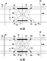
- FIG. 3A depicts a sensing plane 300 of a hybrid flowmeter that is shown having transducers 221a, 222a, 223a, and 224a and reflectors 311 and 312 combining 2 multi-reflective paths (3 reflections each) shown as 321 and 322, and 2 direct-paths shown as 323 and 324.
- the sensor planes described above such as the first plane 200a, second plane 200b, and third plane 200c of the hybrid flowmeters 200 described above, each provide 2 single-reflective paths and 2 direct-paths.
- FIG. 3B depicts a sensing plane 340 of a hybrid flowmeter that combines 2 single-reflective paths shown as 361 and 362, 2 multi-reflective paths shown as 363 and 364, and 2 direct-paths shown as 365 and 366.
- the transducers 221a, 222a, 223a, and 224a have radiation characteristics configured to transmit a wide angle of transmission ultrasonic beam to provide the respective reflective paths along with the direct-paths shown.
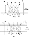
- FIG. 3C depicts an inner sensing plane 370 (e.g. plane 2 in a 3 plane hybrid flowmeter) of a hybrid flowmeter that combines 2 single-reflective paths shown as 381 and 382, 2 multi-reflective paths shown as 383 and 384, and 2 direct-paths shown as 385 and 386.
- the reflectors 311 and 312 shown in FIGs. 3A and 3B are not needed due to signals in the center plane having as low scattering effect, and the transducers 221b, 222b, 223b, and 224b in sensing plane 340 in FIG. 3B each transmit a wide angle of transmission ultrasonic beam to allow the single reflective paths, multi-reflective paths along with the 2 direct-paths.
- FIG. 4 depicts an inner sensing plane 400 (e.g. plane 2 in a 3 plane embodiment) of a hybrid flowmeter having transducers 221c, 222c, 223c, and 224c that combines the 2 single-reflective paths 381 and 382, 2 multi-reflective paths 383 and 384, and 2 direct-paths 385 and 386 shown in FIG. 3C , along with 2 additional 0°-direct-paths, according to an example embodiment.
- Advantages of including 0° paths include enabling further diagnostics including measuring the speed of sound or to calculate the path arrangements (path length, axial distance) with a linear equation system.
- Reception of either direct or reflected signals can generally be realized using existing flowmeter electronics.
- the ultrasonic meter electronics can be extended to include known multi-receiver signal processing functionality, such as one receiver for receiving direct signals and one receiver for receiving reflected signals.
- Time division multiplexing (TDM) may also be used to enable a single receiver to receive both direct signals and reflected signals.
- Disclosed hybrid sensing can be extended from a single plane to any number of planes.
- Disclosed hybrid flowmeters have several significant advantages.
- One advantage is realizing additional reflective path meters in a direct-path arrangement without the need for any additional transducers.
- Applied to custody transfer meter applications disclosed hybrid flowmeters provide the advantage of extending the recalibration period which can provide a decreased number of needed recalibrations in a flowmeter lifetime. Recalibration is known to be a cost intensive process for the customer because the flowmeter has to be demounted from the pipeline and then sent to a calibration lab.
- Another advantage is by adding a check reflective path or multiple redundant reflective paths to a direct-path arrangement leads to increased meter accuracy when additional flow data obtained from the redundant flowmeter paths provided is included in main flow measurement.
Claims (11)
- Hybrid-Ultraschallflussmesser (100), umfassend:einen Messerkörper (105) einschließlich einer Messerrohrwand (105a);mindestens eine erste Erfassungsebene (200a) einschließlich mindestens vier Ultraschallwandlern (101, 102, 103, 104), die in einer Parallelogrammanordnung an der Messerrohrwand (105a) positioniert sind, einschließlich einem ersten Wandlerpaar (101, 103) und einem zweiten Wandlerpaar (102, 104);einen ersten Ultraschallreflektor (111), der zwischen dem ersten Wandlerpaar auf einem ersten Abschnitt (1051) der Messerrohrwand (105a) positioniert ist, und einen zweiten Ultraschallreflektor (112) zwischen dem zweiten Wandlerpaar auf einem zweiten Abschnitt (1052) der Messerrohrwand (105a) gegenüber dem ersten Wandabschnitt (1051);wobei die vier Wandler Anordnungswinkel und Emissionsmuster zum Emittieren eines Ultraschallstrahls aufweisen, um eine Vielzahl von direkten Messpfaden, die mindestens einen ersten und zweiten direkten Messpfad (136, 137) einschließt, und eine Vielzahl von Reflexionspfaden bereitzustellen, die mindestens einen ersten Reflexionspfad (131), der das erste Wandlerpaar und den ersten Ultraschallreflektor (111) erfordert, und einen zweiten Reflexionspfad (132) einschließt, der das zweite Wandlerpaar und den zweiten Ultraschallreflektor (112) erfordert, undein Flusselektronikmodul (120) einschließlich einem Transceiver, der mit einem Prozessor (121) gekoppelt ist, der einen zugehörigen Speicher (122) aufweist, der einen Flussmessalgorithmus speichert, der mit den vier Wandlern gekoppelt ist, um zu bewirken, dass die vier Wandler Ultraschallsignale übertragen, zum Empfangen von Erfassungssignalen, die durch die vier Wandler erzeugt werden, und zum Bestimmen eines Volumenflusses eines Fluids, das durch den Hybrid-Ultraschallflussmesser (100) strömt.
- Hybrid-Ultraschallflussmesser nach Anspruch 1, wobei die Anordnungswinkel und Emissionsmuster dazu ausgelegt sind, dass der erste Reflexionspfad (131) und der zweite Reflexionspfad (132) beide Einzelreflexionspfade sind.
- Hybrid-Ultraschallflussmesser nach Anspruch 1, wobei die Anordnungswinkel und Emissionsmuster dazu ausgelegt sind, dass der erste Reflexionspfad (131) und der zweite Reflexionspfad (132) beide Mehrfachreflexionspfade sind.
- Hybrid-Ultraschallflussmesser nach Anspruch 1, wobei die Anordnungswinkel und Emissionsmuster dazu ausgelegt sind, dass die Vielzahl von Reflexionspfaden sowohl Einzelreflexionspfade als auch Mehrfachreflexionspfade einschließt.
- Hybrid-Ultraschallflussmesser nach Anspruch 1, der zusätzlich zu der ersten Erfassungsebene (200a) ferner eine zweite Erfassungsebene (200b) und eine dritte Erfassungsebene (200c) einschließt, wobei die erste, zweite und dritte Erfassungsebene parallel zueinander sind.
- Hybrid-Ultraschallflussmesser nach Anspruch 1, wobei das Flusselektronikmodul eine empfängergleichlaufende Mehrfachsignal-Verarbeitungsfunktionalität zum gleichzeitigen Verarbeiten von Daten von der Vielzahl von Reflexionspfaden und Daten von einer Vielzahl von Direktpfaden einschließt.
- Verfahren zur Ultraschallflusserfassung, umfassend:Bereitstellen eines Hybrid-Ultraschallflussmessers (100) zwischen Rohrleitungsabschnitten (130a, 130b), durch die ein Fluid strömt, der mindestens vier Ultraschallwandler einschließt, die mindestens eine erste Erfassungsebene (200a) mit Messpfaden bereitstellen, die eine Vielzahl von Reflexionspfaden (131, 132) und eine Vielzahl von Direktpfaden (136, 137) einschließen;Flusserfassung unter Verwendung der Vielzahl von Reflexionspfaden;Flusserfassung unter Verwendung der Vielzahl von Direktpfaden undNutzen von Daten, die von der Flusserfassung unter Verwendung der Vielzahl von Reflexionspfaden erhalten wurden, zusammen mit Daten, die von der Flusserfassung unter Verwendung der Vielzahl von Direktpfaden erhalten wurden;wobei die vier Wandler in einer Parallelogrammanordnung an einer Messerrohrwand positioniert sind und ein erstes Wandlerpaar (101, 103) und ein zweites Wandlerpaar (102, 104), einen ersten Ultraschallreflektor (111), der zwischen dem ersten Wandlerpaar auf einem ersten Abschnitt (1051) der Messerrohrwand (105a) positioniert ist, und einen zweiten Ultraschallreflektor (112) zwischen dem zweiten Wandlerpaar auf einem zweiten Abschnitt (1052) der Messerrohrwand gegenüber dem ersten Wandabschnitt (1051) einschließen, wobei die vier Wandler Anordnungswinkel und Emissionsmuster zum Emittieren eines Ultraschallstrahls aufweisen, um die Vielzahl von Direktpfaden, die einen ersten (136) und zweiten (137) Direktmesspfad einschließt, und die Vielzahl von Reflexionspfaden, die einen ersten Reflexionspfad (131), der das erste Wandlerpaar und den ersten Ultraschallreflektor erfordert, und einen zweiten Reflexionspfad (132) einschließt, der das zweite Wandlerpaar und den zweiten Ultraschallreflektor erfordert.
- Verfahren nach Anspruch 7, das zusätzlich zu der ersten Erfassungsebene (200a) ferner eine zweite Erfassungsebene (200b) und eine dritte Erfassungsebene (200c) bereitstellt, wobei die erste, zweite und dritte Erfassungsebene parallel zueinander sind.
- Verfahren nach Anspruch 7, wobei der erste Reflexionspfad (131) und der zweite Reflexionspfad (132) Einzelreflexionspfade sind.
- Verfahren nach Anspruch 7, wobei der erste Reflexionspfad und der zweite Reflexionspfad Mehrfachreflexionspfade sind.
- Verfahren nach Anspruch 7, wobei die Vielzahl von Reflexionspfaden sowohl Einzelreflexionspfade als auch Mehrfachreflexionspfade einschließt.
Applications Claiming Priority (2)
| Application Number | Priority Date | Filing Date | Title |
|---|---|---|---|
| US14/643,849 US9453749B1 (en) | 2015-03-10 | 2015-03-10 | Hybrid sensing ultrasonic flowmeter |
| PCT/US2016/020021 WO2016144585A1 (en) | 2015-03-10 | 2016-02-29 | Hybrid sensing ultrasonic flowmeter |
Publications (3)
| Publication Number | Publication Date |
|---|---|
| EP3268701A1 EP3268701A1 (de) | 2018-01-17 |
| EP3268701A4 EP3268701A4 (de) | 2018-11-21 |
| EP3268701B1 true EP3268701B1 (de) | 2022-10-12 |
Family
ID=56880466
Family Applications (1)
| Application Number | Title | Priority Date | Filing Date |
|---|---|---|---|
| EP16762132.5A Active EP3268701B1 (de) | 2015-03-10 | 2016-02-29 | Hybrid-ultraschallflussmesser |
Country Status (3)
| Country | Link |
|---|---|
| US (1) | US9453749B1 (de) |
| EP (1) | EP3268701B1 (de) |
| WO (1) | WO2016144585A1 (de) |
Families Citing this family (27)
| Publication number | Priority date | Publication date | Assignee | Title |
|---|---|---|---|---|
| JP6582368B2 (ja) * | 2014-07-23 | 2019-10-02 | 東京電力ホールディングス株式会社 | 流量計測装置および流量計測方法 |
| DE102014115203B3 (de) * | 2014-10-20 | 2016-03-24 | Flexim Flexible Industriemesstechnik Gmbh | Verfahren und Anordnung zur Ultraschall-Clamp-on-Durchflussmessung und Schaltungsanordnung zur Steuerung einer Ultraschall-Clamp-on-Durchflussmessung |
| CN105738649B (zh) * | 2014-12-10 | 2020-02-07 | 通用电气公司 | 用于计算流速的系统和方法 |
| US9962796B2 (en) * | 2015-06-26 | 2018-05-08 | Data Point Targets LLC | Pipe locating system |
| DE102016125745B4 (de) * | 2016-12-27 | 2021-12-23 | Krohne Ag | Ultraschalldurchflussmessgerät und Verfahren zur Messung des Durchflusses |
| EA201991560A1 (ru) | 2017-01-17 | 2020-01-30 | Рубикон Ресёрч Пти Лтд | Измерение потока |
| EP3418697A1 (de) | 2017-06-23 | 2018-12-26 | Flexim Flexible Industriemesstechnik Gmbh | Vorrichtung und verfahren zur ultraschall-durchflussmessung |
| US10495499B2 (en) * | 2017-10-27 | 2019-12-03 | METER Group, Inc. USA | Sonic anemometer |
| EP3489634B1 (de) * | 2017-11-22 | 2020-08-05 | Levitronix GmbH | Ultraschall-messvorrichtung und verfahren zur ultraschallmessung an einem strömenden fluid |
| US10557732B2 (en) * | 2017-12-07 | 2020-02-11 | Cameron International Corporation | Flowmeters and methods of manufacture |
| EP3521774B1 (de) * | 2018-02-06 | 2020-04-01 | SICK Engineering GmbH | Ultraschall-durchflussmessvorrichtung und verfahren zum bestimmen der strömungsgeschwindigkeit |
| CN108179682A (zh) * | 2018-03-01 | 2018-06-19 | 福建铁拓机械有限公司 | 连续式沥青混合料搅拌设备的沥青在线标定装置及方法 |
| US10852173B2 (en) * | 2018-12-18 | 2020-12-01 | Sensia Llc | Flowmeters and methods of manufacture |
| DE102019108189A1 (de) | 2019-03-29 | 2020-10-01 | Krohne Ag | Ultraschalldurchflussmessgerät, Verfahren zum Betreiben eines Ultraschall-Durchflussmessgeräts, Messverbund und Verfahren zum Betreiben eines Messverbunds |
| WO2020216989A1 (en) * | 2019-04-24 | 2020-10-29 | Teknologian Tutkimuskeskus Vtt Oy | Method for manufacturing a pipe for a pipeline and a pipe |
| US11231311B2 (en) | 2019-05-31 | 2022-01-25 | Perceptive Sensor Technologies Llc | Non-linear ultrasound method and apparatus for quantitative detection of materials |
| EP3748308A1 (de) * | 2019-06-07 | 2020-12-09 | Focus-On V.O.F. | Ultraschalldurchflussmessgerät, verwendung eines ultraschalldurchflussmessgerätes in einem absperrorgan und absperrorgan |
| CN114787589A (zh) * | 2019-12-23 | 2022-07-22 | 贝利莫控股公司 | 用于测量经过通道的气体的流量的系统和方法 |
| KR102410147B1 (ko) * | 2020-02-03 | 2022-06-17 | (주)에이치에스씨엠티 | 유량 비교 기능을 구비한 초음파 유량계 |
| CN112019989B (zh) * | 2020-08-13 | 2022-01-28 | 浙江苍南仪表集团股份有限公司 | 超声波换能器动态性能测试装置 |
| WO2022120074A1 (en) | 2020-12-02 | 2022-06-09 | Perceptive Sensor Technologies Llc | Variable angle transducer interface block |
| US11788904B2 (en) | 2020-12-04 | 2023-10-17 | Perceptive Sensor Technologies, Inc. | Acoustic temperature measurement in layered environments |
| US11585690B2 (en) * | 2020-12-04 | 2023-02-21 | Perceptive Sensor Technologies, Inc. | Multi-path acoustic signal improvement for material detection |
| CN116888468A (zh) | 2020-12-30 | 2023-10-13 | 感知传感器技术股份有限公司 | 用信号评估流体质量 |
| WO2023154514A1 (en) | 2022-02-11 | 2023-08-17 | Perceptive Sensor Technologies, Inc. | Acoustic signal detection of material composition in static and dynamic conditions |
| CN114166298A (zh) * | 2022-02-14 | 2022-03-11 | 青岛鼎信通讯股份有限公司 | 一种基于一发双收换能器的多声道超声波水表 |
| US11940420B2 (en) | 2022-07-19 | 2024-03-26 | Perceptive Sensor Technologies, Inc. | Acoustic signal material identification with nanotube couplant |
Citations (1)
| Publication number | Priority date | Publication date | Assignee | Title |
|---|---|---|---|---|
| US3555899A (en) * | 1966-11-01 | 1971-01-19 | Tokyo Keiki Seizosho Co Ltd | Ultrasonic flow quantity measuring system |
Family Cites Families (16)
| Publication number | Priority date | Publication date | Assignee | Title |
|---|---|---|---|---|
| US4024760A (en) * | 1975-07-25 | 1977-05-24 | Westinghouse Electric Corporation | Fluid flow measurement apparatus |
| GB2139755B (en) * | 1983-05-11 | 1987-03-04 | British Gas Corp | Ultrasonic flowmeter |
| US5437194A (en) * | 1991-03-18 | 1995-08-01 | Panametrics, Inc. | Ultrasonic transducer system with temporal crosstalk isolation |
| NL1001719C2 (nl) * | 1995-11-22 | 1997-05-23 | Krohne Altometer | Werkwijze en inrichting voor de ultrasone meting van de snelheid en doorstroomhoeveelheid van een medium in een buisleiding. |
| AUPQ061399A0 (en) * | 1999-05-27 | 1999-06-17 | University Of Sydney, The | Acoustic flow meters |
| US6595071B1 (en) * | 2000-01-06 | 2003-07-22 | Transoma Medical, Inc. | Estimation of error angle in ultrasound flow measurement |
| US6732595B2 (en) | 2002-07-18 | 2004-05-11 | Panametrics, Inc. | Method of and system for determining the mass flow rate of a fluid flowing in a conduit |
| DE102007004936B4 (de) * | 2006-12-19 | 2011-01-13 | Krohne Ag | Ultraschalldurchflußmeßgerät |
| US7658114B1 (en) | 2008-11-17 | 2010-02-09 | General Electric Company | Ultrasonic flow meter |
| US7942068B2 (en) | 2009-03-11 | 2011-05-17 | Ge Infrastructure Sensing, Inc. | Method and system for multi-path ultrasonic flow rate measurement |
| EP2386835B1 (de) | 2010-05-12 | 2015-11-25 | SICK Engineering GmbH | Ultraschallmessung der Strömungsgeschwindigkeit eines Fluids in einer Rohrleitung |
| US8544343B2 (en) | 2010-11-19 | 2013-10-01 | Cameron International Corporation | Chordal gas flowmeter with transducers installed outside the pressure boundary |
| DE102011075997A1 (de) * | 2011-05-17 | 2012-11-22 | Endress + Hauser Flowtec Ag | Ultraschall-Durchflussmessgerät |
| DE102011079250A1 (de) * | 2011-07-15 | 2013-01-17 | Endress + Hauser Flowtec Ag | Ultraschall-Durchflussmessgerät |
| US9612141B2 (en) * | 2013-04-25 | 2017-04-04 | Woojin Inc. | Ultrasonic flow measurement system |
| US9304024B2 (en) * | 2014-01-13 | 2016-04-05 | Cameron International Corporation | Acoustic flow measurement device including a plurality of chordal planes each having a plurality of axial velocity measurements using transducer pairs |
-
2015
- 2015-03-10 US US14/643,849 patent/US9453749B1/en active Active
-
2016
- 2016-02-29 EP EP16762132.5A patent/EP3268701B1/de active Active
- 2016-02-29 WO PCT/US2016/020021 patent/WO2016144585A1/en active Application Filing
Patent Citations (1)
| Publication number | Priority date | Publication date | Assignee | Title |
|---|---|---|---|---|
| US3555899A (en) * | 1966-11-01 | 1971-01-19 | Tokyo Keiki Seizosho Co Ltd | Ultrasonic flow quantity measuring system |
Also Published As
| Publication number | Publication date |
|---|---|
| US20160265954A1 (en) | 2016-09-15 |
| EP3268701A4 (de) | 2018-11-21 |
| WO2016144585A1 (en) | 2016-09-15 |
| EP3268701A1 (de) | 2018-01-17 |
| US9453749B1 (en) | 2016-09-27 |
Similar Documents
| Publication | Publication Date | Title |
|---|---|---|
| EP3268701B1 (de) | Hybrid-ultraschallflussmesser | |
| CA2702666C (en) | A method and system for detecting deposit buildup within an ultrasonic flow meter | |
| US9097567B2 (en) | Ultrasonic, flow measuring device | |
| US9528866B2 (en) | Ultrasonic flow measuring device having a signal path of multiple straight subsection having a minimum separation in the range of 0.4-0.6r from the tube axis | |
| US9279707B2 (en) | Ultrasonic multipath flow measuring device ascertaining weighing factors for measuring paths | |
| JP5222858B2 (ja) | 超音波流量計システム | |
| EP2310809B1 (de) | System und verfahren für einen akustischen flussmesser mit doppelter flussmessung | |
| US9140594B2 (en) | Ultrasonic, flow measuring device | |
| GB2521661A (en) | Apparatus and method for measuring flow | |
| EP2513611B1 (de) | Ultraschallwandler, durchflussmesser und verfahren | |
| US7523676B2 (en) | Ultrasonic flow rate measurement method and system | |
| US10330509B2 (en) | Method and arrangement for an ultrasound clamp-on flow measurement and circuit arrangement for control of an ultrasound clamp-on flow measurement | |
| CN114088151B (zh) | 外夹式多声道超声波流量检测装置及检测方法 | |
| US20230243683A1 (en) | Flowmeter and method for meausuring the flow of a fluid | |
| JP4535065B2 (ja) | ドップラー式超音波流量計 | |
| US10890471B2 (en) | Method and assembly for ultrasonic clamp-on flow measurement, and bodies for implementing off-center flow measurement | |
| JP2002520583A (ja) | マルチコード流量計 | |
| US7845240B1 (en) | Device and method for determining a flow characteristic of a fluid in a conduit | |
| EP2657658B1 (de) | Ultraschallströmungsmesssystem | |
| KR100935876B1 (ko) | 초음파 유속측정방법 및 초음파 유량측정방법 | |
| JP7151311B2 (ja) | 超音波流量計 | |
| CN106092228A (zh) | 超声波式累计热量计 | |
| KR100993617B1 (ko) | 외벽부착식 초음파 다회선 유량계 | |
| CN111473827A (zh) | V形声道零飘消除方法 | |
| JPH10239125A (ja) | 超音波流量計 |
Legal Events
| Date | Code | Title | Description |
|---|---|---|---|
| STAA | Information on the status of an ep patent application or granted ep patent |
Free format text: STATUS: THE INTERNATIONAL PUBLICATION HAS BEEN MADE |
|
| PUAI | Public reference made under article 153(3) epc to a published international application that has entered the european phase |
Free format text: ORIGINAL CODE: 0009012 |
|
| STAA | Information on the status of an ep patent application or granted ep patent |
Free format text: STATUS: REQUEST FOR EXAMINATION WAS MADE |
|
| 17P | Request for examination filed |
Effective date: 20170824 |
|
| AK | Designated contracting states |
Kind code of ref document: A1 Designated state(s): AL AT BE BG CH CY CZ DE DK EE ES FI FR GB GR HR HU IE IS IT LI LT LU LV MC MK MT NL NO PL PT RO RS SE SI SK SM TR |
|
| AX | Request for extension of the european patent |
Extension state: BA ME |
|
| DAV | Request for validation of the european patent (deleted) | ||
| DAX | Request for extension of the european patent (deleted) | ||
| A4 | Supplementary search report drawn up and despatched |
Effective date: 20181018 |
|
| RIC1 | Information provided on ipc code assigned before grant |
Ipc: G01F 15/00 20060101ALN20181012BHEP Ipc: G01F 1/66 20060101AFI20181012BHEP |
|
| STAA | Information on the status of an ep patent application or granted ep patent |
Free format text: STATUS: EXAMINATION IS IN PROGRESS |
|
| 17Q | First examination report despatched |
Effective date: 20220112 |
|
| GRAP | Despatch of communication of intention to grant a patent |
Free format text: ORIGINAL CODE: EPIDOSNIGR1 |
|
| STAA | Information on the status of an ep patent application or granted ep patent |
Free format text: STATUS: GRANT OF PATENT IS INTENDED |
|
| RIC1 | Information provided on ipc code assigned before grant |
Ipc: G01F 25/10 20220101ALN20220616BHEP Ipc: G01F 15/00 20060101ALN20220616BHEP Ipc: G01F 1/667 20220101ALI20220616BHEP Ipc: G01F 1/66 20060101AFI20220616BHEP |
|
| INTG | Intention to grant announced |
Effective date: 20220704 |
|
| GRAS | Grant fee paid |
Free format text: ORIGINAL CODE: EPIDOSNIGR3 |
|
| GRAA | (expected) grant |
Free format text: ORIGINAL CODE: 0009210 |
|
| STAA | Information on the status of an ep patent application or granted ep patent |
Free format text: STATUS: THE PATENT HAS BEEN GRANTED |
|
| AK | Designated contracting states |
Kind code of ref document: B1 Designated state(s): AL AT BE BG CH CY CZ DE DK EE ES FI FR GB GR HR HU IE IS IT LI LT LU LV MC MK MT NL NO PL PT RO RS SE SI SK SM TR |
|
| REG | Reference to a national code |
Ref country code: GB Ref legal event code: FG4D |
|
| REG | Reference to a national code |
Ref country code: CH Ref legal event code: EP |
|
| REG | Reference to a national code |
Ref country code: DE Ref legal event code: R096 Ref document number: 602016075607 Country of ref document: DE |
|
| REG | Reference to a national code |
Ref country code: IE Ref legal event code: FG4D |
|
| REG | Reference to a national code |
Ref country code: AT Ref legal event code: REF Ref document number: 1524425 Country of ref document: AT Kind code of ref document: T Effective date: 20221115 |
|
| REG | Reference to a national code |
Ref country code: LT Ref legal event code: MG9D |
|
| REG | Reference to a national code |
Ref country code: NL Ref legal event code: MP Effective date: 20221012 |
|
| REG | Reference to a national code |
Ref country code: AT Ref legal event code: MK05 Ref document number: 1524425 Country of ref document: AT Kind code of ref document: T Effective date: 20221012 |
|
| PG25 | Lapsed in a contracting state [announced via postgrant information from national office to epo] |
Ref country code: NL Free format text: LAPSE BECAUSE OF FAILURE TO SUBMIT A TRANSLATION OF THE DESCRIPTION OR TO PAY THE FEE WITHIN THE PRESCRIBED TIME-LIMIT Effective date: 20221012 |
|
| PG25 | Lapsed in a contracting state [announced via postgrant information from national office to epo] |
Ref country code: SE Free format text: LAPSE BECAUSE OF FAILURE TO SUBMIT A TRANSLATION OF THE DESCRIPTION OR TO PAY THE FEE WITHIN THE PRESCRIBED TIME-LIMIT Effective date: 20221012 Ref country code: PT Free format text: LAPSE BECAUSE OF FAILURE TO SUBMIT A TRANSLATION OF THE DESCRIPTION OR TO PAY THE FEE WITHIN THE PRESCRIBED TIME-LIMIT Effective date: 20230213 Ref country code: NO Free format text: LAPSE BECAUSE OF FAILURE TO SUBMIT A TRANSLATION OF THE DESCRIPTION OR TO PAY THE FEE WITHIN THE PRESCRIBED TIME-LIMIT Effective date: 20230112 Ref country code: LT Free format text: LAPSE BECAUSE OF FAILURE TO SUBMIT A TRANSLATION OF THE DESCRIPTION OR TO PAY THE FEE WITHIN THE PRESCRIBED TIME-LIMIT Effective date: 20221012 Ref country code: FI Free format text: LAPSE BECAUSE OF FAILURE TO SUBMIT A TRANSLATION OF THE DESCRIPTION OR TO PAY THE FEE WITHIN THE PRESCRIBED TIME-LIMIT Effective date: 20221012 Ref country code: ES Free format text: LAPSE BECAUSE OF FAILURE TO SUBMIT A TRANSLATION OF THE DESCRIPTION OR TO PAY THE FEE WITHIN THE PRESCRIBED TIME-LIMIT Effective date: 20221012 Ref country code: AT Free format text: LAPSE BECAUSE OF FAILURE TO SUBMIT A TRANSLATION OF THE DESCRIPTION OR TO PAY THE FEE WITHIN THE PRESCRIBED TIME-LIMIT Effective date: 20221012 |
|
| PGFP | Annual fee paid to national office [announced via postgrant information from national office to epo] |
Ref country code: FR Payment date: 20230223 Year of fee payment: 8 |
|
| PG25 | Lapsed in a contracting state [announced via postgrant information from national office to epo] |
Ref country code: RS Free format text: LAPSE BECAUSE OF FAILURE TO SUBMIT A TRANSLATION OF THE DESCRIPTION OR TO PAY THE FEE WITHIN THE PRESCRIBED TIME-LIMIT Effective date: 20221012 Ref country code: PL Free format text: LAPSE BECAUSE OF FAILURE TO SUBMIT A TRANSLATION OF THE DESCRIPTION OR TO PAY THE FEE WITHIN THE PRESCRIBED TIME-LIMIT Effective date: 20221012 Ref country code: LV Free format text: LAPSE BECAUSE OF FAILURE TO SUBMIT A TRANSLATION OF THE DESCRIPTION OR TO PAY THE FEE WITHIN THE PRESCRIBED TIME-LIMIT Effective date: 20221012 Ref country code: IS Free format text: LAPSE BECAUSE OF FAILURE TO SUBMIT A TRANSLATION OF THE DESCRIPTION OR TO PAY THE FEE WITHIN THE PRESCRIBED TIME-LIMIT Effective date: 20230212 Ref country code: HR Free format text: LAPSE BECAUSE OF FAILURE TO SUBMIT A TRANSLATION OF THE DESCRIPTION OR TO PAY THE FEE WITHIN THE PRESCRIBED TIME-LIMIT Effective date: 20221012 Ref country code: GR Free format text: LAPSE BECAUSE OF FAILURE TO SUBMIT A TRANSLATION OF THE DESCRIPTION OR TO PAY THE FEE WITHIN THE PRESCRIBED TIME-LIMIT Effective date: 20230113 |
|
| PGFP | Annual fee paid to national office [announced via postgrant information from national office to epo] |
Ref country code: GB Payment date: 20230214 Year of fee payment: 8 Ref country code: DE Payment date: 20230227 Year of fee payment: 8 |
|
| P01 | Opt-out of the competence of the unified patent court (upc) registered |
Effective date: 20230414 |
|
| REG | Reference to a national code |
Ref country code: DE Ref legal event code: R097 Ref document number: 602016075607 Country of ref document: DE |
|
| PG25 | Lapsed in a contracting state [announced via postgrant information from national office to epo] |
Ref country code: SM Free format text: LAPSE BECAUSE OF FAILURE TO SUBMIT A TRANSLATION OF THE DESCRIPTION OR TO PAY THE FEE WITHIN THE PRESCRIBED TIME-LIMIT Effective date: 20221012 Ref country code: RO Free format text: LAPSE BECAUSE OF FAILURE TO SUBMIT A TRANSLATION OF THE DESCRIPTION OR TO PAY THE FEE WITHIN THE PRESCRIBED TIME-LIMIT Effective date: 20221012 Ref country code: EE Free format text: LAPSE BECAUSE OF FAILURE TO SUBMIT A TRANSLATION OF THE DESCRIPTION OR TO PAY THE FEE WITHIN THE PRESCRIBED TIME-LIMIT Effective date: 20221012 Ref country code: DK Free format text: LAPSE BECAUSE OF FAILURE TO SUBMIT A TRANSLATION OF THE DESCRIPTION OR TO PAY THE FEE WITHIN THE PRESCRIBED TIME-LIMIT Effective date: 20221012 Ref country code: CZ Free format text: LAPSE BECAUSE OF FAILURE TO SUBMIT A TRANSLATION OF THE DESCRIPTION OR TO PAY THE FEE WITHIN THE PRESCRIBED TIME-LIMIT Effective date: 20221012 |
|
| PLBE | No opposition filed within time limit |
Free format text: ORIGINAL CODE: 0009261 |
|
| STAA | Information on the status of an ep patent application or granted ep patent |
Free format text: STATUS: NO OPPOSITION FILED WITHIN TIME LIMIT |
|
| PG25 | Lapsed in a contracting state [announced via postgrant information from national office to epo] |
Ref country code: SK Free format text: LAPSE BECAUSE OF FAILURE TO SUBMIT A TRANSLATION OF THE DESCRIPTION OR TO PAY THE FEE WITHIN THE PRESCRIBED TIME-LIMIT Effective date: 20221012 Ref country code: AL Free format text: LAPSE BECAUSE OF FAILURE TO SUBMIT A TRANSLATION OF THE DESCRIPTION OR TO PAY THE FEE WITHIN THE PRESCRIBED TIME-LIMIT Effective date: 20221012 |
|
| 26N | No opposition filed |
Effective date: 20230713 |
|
| PG25 | Lapsed in a contracting state [announced via postgrant information from national office to epo] |
Ref country code: MC Free format text: LAPSE BECAUSE OF FAILURE TO SUBMIT A TRANSLATION OF THE DESCRIPTION OR TO PAY THE FEE WITHIN THE PRESCRIBED TIME-LIMIT Effective date: 20221012 |
|
| REG | Reference to a national code |
Ref country code: CH Ref legal event code: PL |
|
| REG | Reference to a national code |
Ref country code: BE Ref legal event code: MM Effective date: 20230228 |
|
| PG25 | Lapsed in a contracting state [announced via postgrant information from national office to epo] |
Ref country code: LU Free format text: LAPSE BECAUSE OF NON-PAYMENT OF DUE FEES Effective date: 20230228 Ref country code: LI Free format text: LAPSE BECAUSE OF NON-PAYMENT OF DUE FEES Effective date: 20230228 Ref country code: CH Free format text: LAPSE BECAUSE OF NON-PAYMENT OF DUE FEES Effective date: 20230228 |
|
| PG25 | Lapsed in a contracting state [announced via postgrant information from national office to epo] |
Ref country code: SI Free format text: LAPSE BECAUSE OF FAILURE TO SUBMIT A TRANSLATION OF THE DESCRIPTION OR TO PAY THE FEE WITHIN THE PRESCRIBED TIME-LIMIT Effective date: 20221012 |
|
| REG | Reference to a national code |
Ref country code: IE Ref legal event code: MM4A |
|
| PG25 | Lapsed in a contracting state [announced via postgrant information from national office to epo] |
Ref country code: IE Free format text: LAPSE BECAUSE OF NON-PAYMENT OF DUE FEES Effective date: 20230228 |
|
| PG25 | Lapsed in a contracting state [announced via postgrant information from national office to epo] |
Ref country code: BE Free format text: LAPSE BECAUSE OF NON-PAYMENT OF DUE FEES Effective date: 20230228 |
|
| PGFP | Annual fee paid to national office [announced via postgrant information from national office to epo] |
Ref country code: DE Payment date: 20240228 Year of fee payment: 9 Ref country code: GB Payment date: 20240220 Year of fee payment: 9 |