EP3268518B1 - Karde mit einem rotierenden element - Google Patents
Karde mit einem rotierenden element Download PDFInfo
- Publication number
- EP3268518B1 EP3268518B1 EP16718458.9A EP16718458A EP3268518B1 EP 3268518 B1 EP3268518 B1 EP 3268518B1 EP 16718458 A EP16718458 A EP 16718458A EP 3268518 B1 EP3268518 B1 EP 3268518B1
- Authority
- EP
- European Patent Office
- Prior art keywords
- conveying surface
- suction
- machine
- designed
- fibres
- Prior art date
- Legal status (The legal status is an assumption and is not a legal conclusion. Google has not performed a legal analysis and makes no representation as to the accuracy of the status listed.)
- Active
Links
Images


Classifications
-
- D—TEXTILES; PAPER
- D01—NATURAL OR MAN-MADE THREADS OR FIBRES; SPINNING
- D01G—PRELIMINARY TREATMENT OF FIBRES, e.g. FOR SPINNING
- D01G15/00—Carding machines or accessories; Card clothing; Burr-crushing or removing arrangements associated with carding or other preliminary-treatment machines
- D01G15/02—Carding machines
- D01G15/12—Details
- D01G15/46—Doffing or like arrangements for removing fibres from carding elements; Web-dividing apparatus; Condensers
- D01G15/465—Doffing arrangements for removing fibres using, or cooperating with, pneumatic means
Definitions
- This invention relates to a carding machine designed preferably to operate in a system for producing padding, which has a particular variability in the type of air processing which may be performed by the machine on the fibres, together with a greater simplicity of management of the configuration of the machine compared with prior art systems.
- the carding machine is used in particular for combing, separating and parallelising the discontinuous fibres which will then be used to create the padding, and for varying the thickness of the layer of fibres which is obtained by the same operations performed by the machine.
- a possible carding machine comprises a first rotary working element, also called the licker-in, and a second rotary working element, also called the drum.
- These elements work the fibres by passing them along a working path which comprises stretches or sectors tangential to the licker-in and drum and which preferably pass along at least one intermediate zone or intermediate "point" interposed between the licker-in and drum, and at which the working of the fibres may also be very intense.
- the air processing is commonly carried out by the passage of the fibres in the vicinity of suction means which add volume to the layer or stream of fibres and determine, for example, an increase in thickness. More specifically, the fibres worked mechanically are conveyed, if necessary with the aid of blower means, on a conveying surface which translates in the vicinity of at least one suction device, in such a way that the fibres can be subjected to the action of the suction device.
- the operators In order to modify the effect of the air processing the operators usually act on the suction power of the at least one suction means and on its rotation speed, as well as on the power of any blower means.
- Example of such devices can be found in document US7003853 , US2987779 , US3641628 and US5303455 .
- the Applicant has found that the versatility and/or flexibility of the air processing may be improved. Moreover, the Applicant has found that a reduction can be obtained in the time necessary to make the modifications to the configuration of the machine which are necessary to vary the effects produced on the fibres by the air processing means.
- the aim of this invention is to provide a carding machine by means of which it is possible to obtain an increase in the air machining flexibility which the machine can perform on the fibres.
- Another aim of the invention is to provide a carding machine where the flexibility is also associated with a greater speed of the operations necessary to modify the configuration of the machine.
- a carding machine comprising a first rotary element, or licker-in, a second rotary element, or drum, first suction means and a conveying surface designed to define a path for working the fibres, whereby part of this path is tangential to the licker-in, part of this path is tangential to the drum and part of this path is tangential to the conveying surface, the conveying surface being designed to receive fibres arriving from the drum and to translate along at least one direction of translation, the working path comprising a suction sector tangential to the conveying surface and of which at least a part is interposed between the conveying surface and the first suction means, the first suction means being designed to act at the suction sector, whereby the conveying surface may adopt several operating conditions whereby the variation of the operating condition adopted by the conveying surface is the variation of the distance between the first suction means and the conveying surface.
- the change of operating condition of the conveying surface determines an extension or a reduction of at least one section of the suction sector.
- the suction effect which the first suction means produces on the fibres which translate along the suction sector therefore undergoes a variation as a result of the variation of the operating condition adopted by the conveying surface.
- the working path comprises an intermediate sector designed to pass along fibres coming from the drum by the action of gravity in such a way that the fibres reach the suction sector.
- the machine comprises blower means designed to act at the intermediate sector.
- the blower means face towards the conveying surface in such a way as to push the fibres towards the conveying surface.
- the first suction means comprises a first rotary suction device. Thanks to the possibility to rotate, the first suction means are designed also to contribute to the movement of the fibres in the direction of translation of the conveying surface.
- the machine comprises second suction means designed to act at the suction sector and located on the opposite part of the conveying surface relative to the first suction means.
- the second suction means act in conjunction with the first suction means to amplify the effect of the first suction means on the volume of the layer of fibres, in particular thanks to the positioning of the second suction means which are on the opposite side of the conveying surface relative to the first suction means, and therefore act on the fibres in a direction at least partly opposite that of the first suction means.
- the machine comprises pneumatic energy recovery means designed to act between the first suction means and the blower means and/or between the second suction means and the blower means.
- the energy recovery means comprise at least one duct which connects the first suction means to the blower means and/or the second suction means to the blower means and, if necessary, at least one valve designed to vary the height which is recirculated, relative to the flow drawn by the first suction means and/or by the second suction means, and thus also the height of the flow which is discharged outside the machine.
- the machine comprises means for moving the conveying surface which are designed to modify the operating condition.
- the movement means are designed to rotate the conveying surface about an axis which is parallel to the axes of rotation of the licker-in and the drum, and located downstream of the conveying surface along the working path.
- the operating condition of the conveying surface is modified by rotating it, in order to meet the need to change the operating condition with the presence of other components of the production plant. In effect, it is preferable that these components, which must then receive the worked fibres, remain fixed with the variation of the operating condition of the conveying surface.
- the licker-in and the drum rotate on at least a same shared plane of rotation.
- the licker-in and the drum rotate in a mutually inverse manner.
- the direction of translation of the conveying surface and the working path of the fibres lie at least partly on the shared plane of rotation, or in any case are at least partly parallel to the same plane.
- the first suction means rotate at least on the shared plane of rotation.
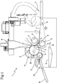
- Figure 1 shows a carding machine 1 according to this invention, comprising a first rotary element, or licker-in 2, a second rotary element, or drum 3, first suction means 4 and a conveying surface 5.
- the licker-in 2, drum 3, first suction means 4 and conveying surface 5 are designed to define a working path L of the fibres tangential partly to the licker-in 2, partly to the drum 3 and partly to the conveying surface 5.
- the conveying surface 5 is designed to receive fibres arriving from the drum 3 and to translate and/or slide along at least a direction of translation X.
- the working path L comprises a suction sector A interposed at least partly between the conveying surface 5 and the first suction means 4.
- the first suction means 4 are designed to act above the suction sector A.
- the conveying surface 5 may adopt several operating conditions in such a way as to vary the relative inclination, for varying the suction section S relative to the suction sector A, as shown clearly for example in Figure 2 .
- the variation of the operating condition adopted by the conveying surface 5 is associated with the variation of the distance between the detachment point from the drum 3 and the conveying surface 5.
- the working path L in the embodiment illustrated of the machine 1, comprises an intermediate sector C interposed between the drum 3 and the suction sector A.
- This intermediate sector C is designed to be passed along by the action of gravity by the fibres arriving from the drum 3, and, basically, is designed to be passed along by the fibres arriving from the drum 3. These fibres, after have covered the intermediate sector, pass along the suction sector A.
- the change of operating condition of the conveying surface 5 determines an extension or a reduction of at least one section S of the suction sector A.
- section S of the suction sector A means a section transversal to the working path L, located at the suction sector A, which is a part of the working path L.
- the working path L on the plane at right angles to the motion of the fibres associated with the working path L, defines in effect a section with a certain two-dimensional extension.
- the suction effect which the first suction means 4 produces on the fibres which translate along the suction sector A therefore undergoes a variation as a result of the variation of the operating condition adopted by the conveying surface 5.
- the cross section S of the suction sector A increases, there will be an increase in the thickness of the layer of fibres which moves along the suction sector A.
- the working path L is indicated in Figures 1 and 2 in a very schematic manner; in effect the thickness of the working path L at the suction sector A does not cover the entire suction section S.
- the working path L is illustrated in order to show the trajectory which is covered by the fibres, without taking into account the extension of the path L transversal to the main motion of the fibres.
- the machine 1 advantageously comprises blower means 6 designed to act at the intermediate sector C.
- the blower means 6 preferably face towards the conveying surface 5, in such a way as to push the fibres towards the conveying surface 5.
- the first suction means 4 comprise a first rotary suction device 4. Moreover, the first suction means 4 are preferably cylindrical.
- the first suction means 4 are designed also to contribute to the movement of the fibres in the direction of translation and/or sliding X of the conveying surface 5.
- the machine advantageously comprises second suction means 7 designed to act at the same suction sector A, but located on the opposite part of the conveying surface 5 relative to the first suction means 4.
- the second suction means 7 are also preferably cylindrical.
- the machine 1 advantageously comprises pneumatic energy recovery means, which are not illustrated in the drawings.
- the recovery means are designed to act between the first suction means 4 and the blower means 6, and/or between the second suction means 7 and the blower means 6.
- the energy recovery means preferably comprise at least one duct which connects the blower means 6 to the first suction means 4 and/or to the second suction means 7.
- These recovery means advantageously comprise at least one valve designed to vary the flow height which is recirculated, relative to the flow drawn by the first suction means 4 and/or by the second suction means 7.
- the valve is designed to also adjust the height of the flow which is discharged outside of the machine 1.
- both the first suction means 4 and the second suction means 7 are of a symmetrical type, that is, they obtain a suction equal from both sides of the machine.
- the double symmetrical suction on both sides of the machine allow a modulating of the right ⁇ left suction to correct for any excess ⁇ lack of material being made.
- the embodiment of the machine 1 shown in the drawings comprises means for moving the conveying surface 5, which are not illustrated in the drawings. These movement means are designed for modifying the operating condition of the conveying surface 5. These movement means are preferably designed to rotate the conveying surface 5 about an axis (O) which is parallel to the axes of rotation of the licker-in 2 and by the drum 3, as shown clearly in Figure 2 .
- This rotation of the conveying surface 5 is performed preferably about the axis O located, along the working path L, downstream of the conveying surface 5.
- One possible solution comprises, on the other hand, the vertical translational movement of the entire conveying surface 5.
- the rotation occurs according to the double arrow B and about an axis of rotation at a right angle to the plane of Figures 1 to 3 and passing through the centre of rotation O.
- the machine 1 is in a first operating configuration such that the conveying surface 5 adopts a first operating condition.
- the first operating condition of the conveying surface 5 corresponds to a certain angular position of the conveying surface 5 around the axis of rotation passing through the centre of rotation O.
- the machine 1 is in a second operating configuration corresponding to a second operating condition of the conveying surface 5.
- the conveying surface 5, relative to its operating condition of Figure 1 is rotated about the axis of rotation passing through O.
- the aim of varying the sector S may also be achieved by keeping the conveying surface 5 fixed and by modifying the height of the drum 3 and, if necessary, the first suction means 4.
- FIG. 3 The embodiment of the machine 1 according to the accompanying drawings is shown in Figure 3 in a third operating configuration, such that the conveying surface 5 is rotated significantly downwards, relative to Figure 1 or also relative to Figure 2 , again around the axis of rotation passing through O. More specifically, in the situation of Figure 3 the conveying surface 5 is designed to receive the fibres arriving from an infeed surface 8, located upstream of the licker-in 2 and the drum 3, without the fibres being worked along the working path L.
- the infeed surface 8, in the first operating configuration and in the second operating configuration of the machine 1, shown in Figures 1 and 2 , respectively, is designed to convey the fibres in such a way that they start to travel along the working path L defined by the machine 1.
- the infeed surface 8 is, on the other hand, oriented in such a way as to convey the fibres directly towards the conveying surface 5, so that the fibres are directed towards one of the components of the same plant after the machine 1, without being worked along the working path L.
- the operating configuration of Figure 3 also comprises a further intermediate surface 9 which acts as a bridge between the infeed surface 8 and the conveying surface 5.
- the conveying surface 5 could be considered, in the embodiment of the machine 1 shown in the accompanying drawings, basically as an outfeed surface of the machine 1, since it is designed to carry the fibres towards the next component after the machine 1 and belonging to the same production plant.
- the infeed surface 8 and the intermediate surface 9 are also preferably slidable and/or translatory parallel to themselves, similarly to the conveying surface 5, which as mentioned above is slidable and/or translatory according to the arrow X.
- the infeed surface 8 and/or the intermediate surface 9 and/or the conveying surface 5 may each comprise at least one conveyor belt.
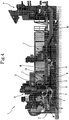
- Figure 4 shows an example of a production plant I in which the embodiment of the machine 1 of Figures 1 to 3 can be advantageously used.
- the plant I comprises, for example, a forming machine F, another carding machine 1', and a cutting unit T.
- Figure 4 also shows the fibres of material M which are worked by the machines F, 1' and 1 of the plant I.
- the cutting unit T is positioned, in the plant I shown in Figure 4 , after the carding machine 1 according to this invention.
- the machine 1, in Figure 4 in an operating configuration such that the fibres are worked by the licker-in 2 and by the drum 3, and then received by the conveying surface 5, similarly to what occurs in operating configurations of Figure 1 and Figure 2 .
- the cutting unit T is also indicated in Figures 1 to 3 , for reasons of consistency with Figure 4 .
- the machine 1 also comprises introductory means suitable for conveying towards the licker-in 2 the fibres arriving from the infeed surface 8.
- introductory means may also advantageously comprise further rotary units, as may be seen in the drawings.
- the machine 1 also comprises rotary doffing and/or working means 11, situated in the proximity of the drum 3, which are preferably designed to work the fibres in conjunction with the drum 3.
- a possible method for using a machine 1 according to the embodiment illustrated in the accompanying drawings comprises the rotation of the licker-in 2 and the drum 3 at least om the same shared plane of rotation, which, for example, coincides with that of Figures 1 to 3 .
- the licker-in 2 and the drum 3 rotate preferably in a mutually inverse manner, and, in the embodiment illustrated, according to arrows D and E, respectively.
- the direction of translation X of the conveying surface 5 and the working path L of the fibres, according to this method lie at least partly on the shared plane of rotation, or in any case are at least partly parallel to the same plane.
- the first suction means 4 rotate at least on the shared plane of rotation.
- the first suction means 4 rotate according to the arrow G.
- the invention makes it possible to achieve the preset aims.
- the type of movement which is imparted by the movement means to the conveying surface 5, in order to vary the operating condition, makes it possible to configure the movement means themselves in such a way as to reduce the dimensions, especially for the purposes of integrating the movement means between the other components of the machine 1 and/or the plant I.
Landscapes
- Engineering & Computer Science (AREA)
- Textile Engineering (AREA)
- Preliminary Treatment Of Fibers (AREA)
Claims (11)
- Karde (1), umfassend ein rotierendes Element oder eine Trommel (3), eine Zufuhrwalze (2), erste Saugmittel (4) und eine Förderoberfläche (5), die ausgestaltet ist, um einen Weg (L) zur Bearbeitung der Fasern zu formen, wobei ein Teil dieses Wegs tangential zur Trommel (3) verläuft und ein Teil dieses Wegs tangential zur Förderoberfläche (5) verläuft, wobei die Förderoberfläche (5) ausgestaltet ist, um Fasern aufzunehmen, die von der Trommel (3) eingehen, und diese entlang mindestens einer Verschieberichtung (X) zu verschieben, wobei der Bearbeitungsweg (L) einen Saugsektor (A) umfasst, von dem mindestens ein Teil zwischen den ersten Saugmitteln (4) und der Förderoberfläche (5) eingesetzt ist, dadurch gekennzeichnet, dass die Förderoberfläche (5) mehrere Betriebszustände einnehmen kann, wobei die Veränderung des Betriebszustands der Förderoberfläche (5) die Veränderung des Abstands zwischen den Saugmitteln (4) und der Förderoberfläche (5) ist.
- Karde (1) nach Anspruch 1, zudem umfassend zweite Saugmittel (7), wobei die ersten Saugmittel (4) ausgestaltet sind, um am Saugsektor (A) zu wirken, und über den zweiten Saugmitteln (7) angeordnet sind.
- Maschine (1) nach Anspruch 1 oder 2, wobei die Veränderung des von der Förderoberfläche (5) eingenommenen Betriebszustands mit der Veränderung des Abstands zwischen einem Punkt (P) der Trennung von der Trommel und der Förderoberfläche (5) assoziiert ist.
- Maschine (1) nach einem der Ansprüche 1 bis 3, wobei der Bearbeitungsweg (L) einen Zwischensektor (C) umfasst, der zum Passieren von Fasern ausgestaltet ist, die durch Schwerkraft von der Trommel eingehen, sodass die Fasern den Saugsektor (A) erreichen.
- Maschine (1) nach Anspruch 4, umfassend Blasmittel (6), die ausgestaltet sind, um am Zwischensektor (C) zu wirken, wobei die Blasmittel (6) der Förderoberfläche (5) zugewandt sind, sodass sie die Fasern hinführend zur Förderoberfläche (5) schieben.
- Maschine (1) nach einem der vorhergehenden Ansprüche, wobei die ersten Saugmittel (4) eine erste rotierende Saugvorrichtung umfassen.
- Maschine (1) nach Anspruch 5, umfassend pneumatische Energierückgewinnungsmittel, die ausgestaltet sind, um zwischen den ersten Saugmitteln (4) und den Blasmitteln (6) zu wirken.
- Maschine (1) nach einem der Ansprüche 2 bis 6, wobei die zweiten Saugmittel (7) ausgestaltet sind, um am Saugsektor (A) zu wirken und am entgegengesetzten Teil der Förderoberfläche (5) relativ zu den ersten Saugmitteln (4) angeordnet sind.
- Maschine (1) nach Anspruch 7 und Anspruch 2, wobei die Energierückgewinnungsmittel ausgelegt sind, um zwischen den zweiten Saugmitteln (7) und den Blasmitteln (6) zu wirken.
- Maschine (1) nach einem der vorhergehenden Ansprüche, umfassend Mittel zum Bewegen der Förderoberfläche (5), die ausgestaltet sind, um den Betriebszustand zu verändern.
- Maschine (1) nach Anspruch 10, wobei die Bewegungsmittel ausgestaltet sind, um die Förderoberfläche (5) um eine Achse (O) zu drehen, die parallel zu den Rotationsachsen der Zufuhrwalze (2) und der Trommel (3) angeordnet ist, wobei die Achse (O) nach der Förderoberfläche (5) entlang des Bearbeitungswegs (L) angeordnet ist.
Applications Claiming Priority (2)
| Application Number | Priority Date | Filing Date | Title |
|---|---|---|---|
| ITFI20150070 | 2015-03-12 | ||
| PCT/IB2016/051360 WO2016142896A1 (en) | 2015-03-12 | 2016-03-10 | A carding machine comprising a rotary element |
Publications (2)
| Publication Number | Publication Date |
|---|---|
| EP3268518A1 EP3268518A1 (de) | 2018-01-17 |
| EP3268518B1 true EP3268518B1 (de) | 2020-06-03 |
Family
ID=53284334
Family Applications (1)
| Application Number | Title | Priority Date | Filing Date |
|---|---|---|---|
| EP16718458.9A Active EP3268518B1 (de) | 2015-03-12 | 2016-03-10 | Karde mit einem rotierenden element |
Country Status (3)
| Country | Link |
|---|---|
| US (1) | US10519571B2 (de) |
| EP (1) | EP3268518B1 (de) |
| WO (1) | WO2016142896A1 (de) |
Families Citing this family (2)
| Publication number | Priority date | Publication date | Assignee | Title |
|---|---|---|---|---|
| DE102019104851A1 (de) * | 2019-02-26 | 2020-08-27 | Adler Pelzer Holding Gmbh | Vorrichtung zur Herstellung von Nadelvliesen |
| IT202000019006A1 (it) * | 2020-08-03 | 2022-02-03 | Technoplants S R L | Macchina cardatrice |
Family Cites Families (4)
| Publication number | Priority date | Publication date | Assignee | Title |
|---|---|---|---|---|
| US2987779A (en) * | 1957-02-05 | 1961-06-13 | Kawashima Kanichi | Doffing process and apparatus for the card by action of air |
| AT296099B (de) * | 1969-02-07 | 1972-01-25 | Fehrer Ernst | Vorrichtung zum Herstellen von Vliesen aus Fasermaterial |
| DE4036014C2 (de) * | 1990-11-13 | 2001-07-05 | Truetzschler Gmbh & Co Kg | Vorrichtung zum Herstellen eines Faservlieses, z.B. aus Chemiefasern, Baumwolle, Zellwolle u. dgl. |
| DE50308225D1 (de) * | 2003-07-29 | 2007-10-31 | Spinnbau Gmbh | Vlieskrempel und Verfahren zur Herstellung eines Faservlieses |
-
2016
- 2016-03-10 WO PCT/IB2016/051360 patent/WO2016142896A1/en not_active Ceased
- 2016-03-10 EP EP16718458.9A patent/EP3268518B1/de active Active
- 2016-03-10 US US15/557,529 patent/US10519571B2/en active Active
Non-Patent Citations (1)
| Title |
|---|
| None * |
Also Published As
| Publication number | Publication date |
|---|---|
| US10519571B2 (en) | 2019-12-31 |
| US20180051400A1 (en) | 2018-02-22 |
| WO2016142896A1 (en) | 2016-09-15 |
| EP3268518A1 (de) | 2018-01-17 |
Similar Documents
| Publication | Publication Date | Title |
|---|---|---|
| JP6035140B2 (ja) | 幅寄せコンベヤおよび仕分設備 | |
| CN104044338B (zh) | 气动辊的规格转换 | |
| EP3268518B1 (de) | Karde mit einem rotierenden element | |
| US7975831B2 (en) | Conveying apparatus for changing the forward motion direction of sheet articles | |
| CN102826254A (zh) | 一种工业炸药震源药柱的自动装箱设备以及工艺 | |
| US8496249B2 (en) | Method and apparatus for diverting printed products into three streams | |
| US20130247735A1 (en) | Cutting device | |
| CN104308889B (zh) | 一种贴膜分切机 | |
| CN106865105B (zh) | 用于传递杆状物品的传递方法和传递设备 | |
| US20140305768A1 (en) | Short Gap Diverter | |
| WO2016142892A1 (en) | A carding machine | |
| CN104353550B (zh) | 湿式粗粒预选磁选机 | |
| CN110650638B (zh) | 用于转移杆状物品的设备和方法和用于转换该物品的设备 | |
| CN105217234A (zh) | 在线自动化动态缓冲系统 | |
| CN106516292A (zh) | 斗式零件分装系统 | |
| CN104583477B (zh) | 交叉式铺网机 | |
| CN108840018A (zh) | 新型调速转弯滚筒输送机 | |
| CN105555682A (zh) | 传送轮和传送系统 | |
| US4474511A (en) | Continuous tobacco feed | |
| CN102152205A (zh) | 磨片机 | |
| CN208131482U (zh) | 一种大型tds智能干选机 | |
| CN107108143A (zh) | 用于允许狭窄环状材料穿过标准织物压实机被加工的装置 | |
| CN205520843U (zh) | 瓦片刀全自动砂带磨床 | |
| CN209567166U (zh) | 一种受控运行系统和相关的包装机 | |
| KR20180125469A (ko) | 위생용 흡수 용품의 측면 플랩을 공급하는 유닛 및 그 공급 유닛의 포맷 변경 방법 |
Legal Events
| Date | Code | Title | Description |
|---|---|---|---|
| STAA | Information on the status of an ep patent application or granted ep patent |
Free format text: STATUS: THE INTERNATIONAL PUBLICATION HAS BEEN MADE |
|
| PUAI | Public reference made under article 153(3) epc to a published international application that has entered the european phase |
Free format text: ORIGINAL CODE: 0009012 |
|
| STAA | Information on the status of an ep patent application or granted ep patent |
Free format text: STATUS: REQUEST FOR EXAMINATION WAS MADE |
|
| 17P | Request for examination filed |
Effective date: 20170911 |
|
| AK | Designated contracting states |
Kind code of ref document: A1 Designated state(s): AL AT BE BG CH CY CZ DE DK EE ES FI FR GB GR HR HU IE IS IT LI LT LU LV MC MK MT NL NO PL PT RO RS SE SI SK SM TR |
|
| AX | Request for extension of the european patent |
Extension state: BA ME |
|
| DAX | Request for extension of the european patent (deleted) | ||
| RAV | Requested validation state of the european patent: fee paid |
Extension state: MA Effective date: 20170911 |
|
| GRAP | Despatch of communication of intention to grant a patent |
Free format text: ORIGINAL CODE: EPIDOSNIGR1 |
|
| STAA | Information on the status of an ep patent application or granted ep patent |
Free format text: STATUS: GRANT OF PATENT IS INTENDED |
|
| INTG | Intention to grant announced |
Effective date: 20200109 |
|
| GRAS | Grant fee paid |
Free format text: ORIGINAL CODE: EPIDOSNIGR3 |
|
| GRAA | (expected) grant |
Free format text: ORIGINAL CODE: 0009210 |
|
| STAA | Information on the status of an ep patent application or granted ep patent |
Free format text: STATUS: THE PATENT HAS BEEN GRANTED |
|
| AK | Designated contracting states |
Kind code of ref document: B1 Designated state(s): AL AT BE BG CH CY CZ DE DK EE ES FI FR GB GR HR HU IE IS IT LI LT LU LV MC MK MT NL NO PL PT RO RS SE SI SK SM TR |
|
| REG | Reference to a national code |
Ref country code: GB Ref legal event code: FG4D |
|
| REG | Reference to a national code |
Ref country code: CH Ref legal event code: EP Ref country code: AT Ref legal event code: REF Ref document number: 1277119 Country of ref document: AT Kind code of ref document: T Effective date: 20200615 |
|
| REG | Reference to a national code |
Ref country code: DE Ref legal event code: R096 Ref document number: 602016037461 Country of ref document: DE |
|
| REG | Reference to a national code |
Ref country code: LT Ref legal event code: MG4D |
|
| PG25 | Lapsed in a contracting state [announced via postgrant information from national office to epo] |
Ref country code: LT Free format text: LAPSE BECAUSE OF FAILURE TO SUBMIT A TRANSLATION OF THE DESCRIPTION OR TO PAY THE FEE WITHIN THE PRESCRIBED TIME-LIMIT Effective date: 20200603 Ref country code: NO Free format text: LAPSE BECAUSE OF FAILURE TO SUBMIT A TRANSLATION OF THE DESCRIPTION OR TO PAY THE FEE WITHIN THE PRESCRIBED TIME-LIMIT Effective date: 20200903 Ref country code: GR Free format text: LAPSE BECAUSE OF FAILURE TO SUBMIT A TRANSLATION OF THE DESCRIPTION OR TO PAY THE FEE WITHIN THE PRESCRIBED TIME-LIMIT Effective date: 20200904 Ref country code: SE Free format text: LAPSE BECAUSE OF FAILURE TO SUBMIT A TRANSLATION OF THE DESCRIPTION OR TO PAY THE FEE WITHIN THE PRESCRIBED TIME-LIMIT Effective date: 20200603 Ref country code: FI Free format text: LAPSE BECAUSE OF FAILURE TO SUBMIT A TRANSLATION OF THE DESCRIPTION OR TO PAY THE FEE WITHIN THE PRESCRIBED TIME-LIMIT Effective date: 20200603 |
|
| REG | Reference to a national code |
Ref country code: NL Ref legal event code: MP Effective date: 20200603 |
|
| PG25 | Lapsed in a contracting state [announced via postgrant information from national office to epo] |
Ref country code: HR Free format text: LAPSE BECAUSE OF FAILURE TO SUBMIT A TRANSLATION OF THE DESCRIPTION OR TO PAY THE FEE WITHIN THE PRESCRIBED TIME-LIMIT Effective date: 20200603 Ref country code: LV Free format text: LAPSE BECAUSE OF FAILURE TO SUBMIT A TRANSLATION OF THE DESCRIPTION OR TO PAY THE FEE WITHIN THE PRESCRIBED TIME-LIMIT Effective date: 20200603 Ref country code: RS Free format text: LAPSE BECAUSE OF FAILURE TO SUBMIT A TRANSLATION OF THE DESCRIPTION OR TO PAY THE FEE WITHIN THE PRESCRIBED TIME-LIMIT Effective date: 20200603 Ref country code: BG Free format text: LAPSE BECAUSE OF FAILURE TO SUBMIT A TRANSLATION OF THE DESCRIPTION OR TO PAY THE FEE WITHIN THE PRESCRIBED TIME-LIMIT Effective date: 20200903 |
|
| REG | Reference to a national code |
Ref country code: AT Ref legal event code: MK05 Ref document number: 1277119 Country of ref document: AT Kind code of ref document: T Effective date: 20200603 |
|
| PG25 | Lapsed in a contracting state [announced via postgrant information from national office to epo] |
Ref country code: AL Free format text: LAPSE BECAUSE OF FAILURE TO SUBMIT A TRANSLATION OF THE DESCRIPTION OR TO PAY THE FEE WITHIN THE PRESCRIBED TIME-LIMIT Effective date: 20200603 Ref country code: NL Free format text: LAPSE BECAUSE OF FAILURE TO SUBMIT A TRANSLATION OF THE DESCRIPTION OR TO PAY THE FEE WITHIN THE PRESCRIBED TIME-LIMIT Effective date: 20200603 |
|
| PG25 | Lapsed in a contracting state [announced via postgrant information from national office to epo] |
Ref country code: SM Free format text: LAPSE BECAUSE OF FAILURE TO SUBMIT A TRANSLATION OF THE DESCRIPTION OR TO PAY THE FEE WITHIN THE PRESCRIBED TIME-LIMIT Effective date: 20200603 Ref country code: RO Free format text: LAPSE BECAUSE OF FAILURE TO SUBMIT A TRANSLATION OF THE DESCRIPTION OR TO PAY THE FEE WITHIN THE PRESCRIBED TIME-LIMIT Effective date: 20200603 Ref country code: CZ Free format text: LAPSE BECAUSE OF FAILURE TO SUBMIT A TRANSLATION OF THE DESCRIPTION OR TO PAY THE FEE WITHIN THE PRESCRIBED TIME-LIMIT Effective date: 20200603 Ref country code: ES Free format text: LAPSE BECAUSE OF FAILURE TO SUBMIT A TRANSLATION OF THE DESCRIPTION OR TO PAY THE FEE WITHIN THE PRESCRIBED TIME-LIMIT Effective date: 20200603 Ref country code: AT Free format text: LAPSE BECAUSE OF FAILURE TO SUBMIT A TRANSLATION OF THE DESCRIPTION OR TO PAY THE FEE WITHIN THE PRESCRIBED TIME-LIMIT Effective date: 20200603 Ref country code: PT Free format text: LAPSE BECAUSE OF FAILURE TO SUBMIT A TRANSLATION OF THE DESCRIPTION OR TO PAY THE FEE WITHIN THE PRESCRIBED TIME-LIMIT Effective date: 20201006 Ref country code: EE Free format text: LAPSE BECAUSE OF FAILURE TO SUBMIT A TRANSLATION OF THE DESCRIPTION OR TO PAY THE FEE WITHIN THE PRESCRIBED TIME-LIMIT Effective date: 20200603 |
|
| PG25 | Lapsed in a contracting state [announced via postgrant information from national office to epo] |
Ref country code: SK Free format text: LAPSE BECAUSE OF FAILURE TO SUBMIT A TRANSLATION OF THE DESCRIPTION OR TO PAY THE FEE WITHIN THE PRESCRIBED TIME-LIMIT Effective date: 20200603 Ref country code: PL Free format text: LAPSE BECAUSE OF FAILURE TO SUBMIT A TRANSLATION OF THE DESCRIPTION OR TO PAY THE FEE WITHIN THE PRESCRIBED TIME-LIMIT Effective date: 20200603 Ref country code: IS Free format text: LAPSE BECAUSE OF FAILURE TO SUBMIT A TRANSLATION OF THE DESCRIPTION OR TO PAY THE FEE WITHIN THE PRESCRIBED TIME-LIMIT Effective date: 20201003 |
|
| REG | Reference to a national code |
Ref country code: DE Ref legal event code: R097 Ref document number: 602016037461 Country of ref document: DE |
|
| PLBE | No opposition filed within time limit |
Free format text: ORIGINAL CODE: 0009261 |
|
| STAA | Information on the status of an ep patent application or granted ep patent |
Free format text: STATUS: NO OPPOSITION FILED WITHIN TIME LIMIT |
|
| PG25 | Lapsed in a contracting state [announced via postgrant information from national office to epo] |
Ref country code: DK Free format text: LAPSE BECAUSE OF FAILURE TO SUBMIT A TRANSLATION OF THE DESCRIPTION OR TO PAY THE FEE WITHIN THE PRESCRIBED TIME-LIMIT Effective date: 20200603 |
|
| 26N | No opposition filed |
Effective date: 20210304 |
|
| PG25 | Lapsed in a contracting state [announced via postgrant information from national office to epo] |
Ref country code: SI Free format text: LAPSE BECAUSE OF FAILURE TO SUBMIT A TRANSLATION OF THE DESCRIPTION OR TO PAY THE FEE WITHIN THE PRESCRIBED TIME-LIMIT Effective date: 20200603 |
|
| PG25 | Lapsed in a contracting state [announced via postgrant information from national office to epo] |
Ref country code: MC Free format text: LAPSE BECAUSE OF FAILURE TO SUBMIT A TRANSLATION OF THE DESCRIPTION OR TO PAY THE FEE WITHIN THE PRESCRIBED TIME-LIMIT Effective date: 20200603 |
|
| REG | Reference to a national code |
Ref country code: CH Ref legal event code: PL |
|
| GBPC | Gb: european patent ceased through non-payment of renewal fee |
Effective date: 20210310 |
|
| REG | Reference to a national code |
Ref country code: BE Ref legal event code: MM Effective date: 20210331 |
|
| PG25 | Lapsed in a contracting state [announced via postgrant information from national office to epo] |
Ref country code: CH Free format text: LAPSE BECAUSE OF NON-PAYMENT OF DUE FEES Effective date: 20210331 Ref country code: LI Free format text: LAPSE BECAUSE OF NON-PAYMENT OF DUE FEES Effective date: 20210331 Ref country code: LU Free format text: LAPSE BECAUSE OF NON-PAYMENT OF DUE FEES Effective date: 20210310 Ref country code: IE Free format text: LAPSE BECAUSE OF NON-PAYMENT OF DUE FEES Effective date: 20210310 Ref country code: GB Free format text: LAPSE BECAUSE OF NON-PAYMENT OF DUE FEES Effective date: 20210310 |
|
| PG25 | Lapsed in a contracting state [announced via postgrant information from national office to epo] |
Ref country code: BE Free format text: LAPSE BECAUSE OF NON-PAYMENT OF DUE FEES Effective date: 20210331 |
|
| PG25 | Lapsed in a contracting state [announced via postgrant information from national office to epo] |
Ref country code: CY Free format text: LAPSE BECAUSE OF FAILURE TO SUBMIT A TRANSLATION OF THE DESCRIPTION OR TO PAY THE FEE WITHIN THE PRESCRIBED TIME-LIMIT Effective date: 20200603 |
|
| P01 | Opt-out of the competence of the unified patent court (upc) registered |
Effective date: 20230529 |
|
| PG25 | Lapsed in a contracting state [announced via postgrant information from national office to epo] |
Ref country code: HU Free format text: LAPSE BECAUSE OF FAILURE TO SUBMIT A TRANSLATION OF THE DESCRIPTION OR TO PAY THE FEE WITHIN THE PRESCRIBED TIME-LIMIT; INVALID AB INITIO Effective date: 20160310 |
|
| PG25 | Lapsed in a contracting state [announced via postgrant information from national office to epo] |
Ref country code: MK Free format text: LAPSE BECAUSE OF FAILURE TO SUBMIT A TRANSLATION OF THE DESCRIPTION OR TO PAY THE FEE WITHIN THE PRESCRIBED TIME-LIMIT Effective date: 20200603 |
|
| VS25 | Lapsed in a validation state [announced via postgrant information from nat. office to epo] |
Ref country code: MA Free format text: LAPSE BECAUSE OF FAILURE TO SUBMIT A TRANSLATION OF THE DESCRIPTION OR TO PAY THE FEE WITHIN THE PRESCRIBED TIME-LIMIT Effective date: 20200603 |
|
| PG25 | Lapsed in a contracting state [announced via postgrant information from national office to epo] |
Ref country code: MT Free format text: LAPSE BECAUSE OF FAILURE TO SUBMIT A TRANSLATION OF THE DESCRIPTION OR TO PAY THE FEE WITHIN THE PRESCRIBED TIME-LIMIT Effective date: 20200603 |
|
| PGFP | Annual fee paid to national office [announced via postgrant information from national office to epo] |
Ref country code: DE Payment date: 20250319 Year of fee payment: 10 |
|
| PGFP | Annual fee paid to national office [announced via postgrant information from national office to epo] |
Ref country code: FR Payment date: 20250324 Year of fee payment: 10 |
|
| PGFP | Annual fee paid to national office [announced via postgrant information from national office to epo] |
Ref country code: IT Payment date: 20250325 Year of fee payment: 10 |
|
| PG25 | Lapsed in a contracting state [announced via postgrant information from national office to epo] |
Ref country code: TR Free format text: LAPSE BECAUSE OF FAILURE TO SUBMIT A TRANSLATION OF THE DESCRIPTION OR TO PAY THE FEE WITHIN THE PRESCRIBED TIME-LIMIT Effective date: 20200603 |