EP3267150A2 - Abtastung mit bildmittelung - Google Patents
Abtastung mit bildmittelung Download PDFInfo
- Publication number
- EP3267150A2 EP3267150A2 EP17175910.3A EP17175910A EP3267150A2 EP 3267150 A2 EP3267150 A2 EP 3267150A2 EP 17175910 A EP17175910 A EP 17175910A EP 3267150 A2 EP3267150 A2 EP 3267150A2
- Authority
- EP
- European Patent Office
- Prior art keywords
- overlapping images
- image
- images
- imaging
- obtaining
- Prior art date
- Legal status (The legal status is an assumption and is not a legal conclusion. Google has not performed a legal analysis and makes no representation as to the accuracy of the status listed.)
- Granted
Links
Images


Classifications
-
- H—ELECTRICITY
- H04—ELECTRIC COMMUNICATION TECHNIQUE
- H04N—PICTORIAL COMMUNICATION, e.g. TELEVISION
- H04N23/00—Cameras or camera modules comprising electronic image sensors; Control thereof
- H04N23/95—Computational photography systems, e.g. light-field imaging systems
- H04N23/951—Computational photography systems, e.g. light-field imaging systems by using two or more images to influence resolution, frame rate or aspect ratio
-
- G—PHYSICS
- G01—MEASURING; TESTING
- G01C—MEASURING DISTANCES, LEVELS OR BEARINGS; SURVEYING; NAVIGATION; GYROSCOPIC INSTRUMENTS; PHOTOGRAMMETRY OR VIDEOGRAMMETRY
- G01C11/00—Photogrammetry or videogrammetry, e.g. stereogrammetry; Photographic surveying
- G01C11/02—Picture taking arrangements specially adapted for photogrammetry or photographic surveying, e.g. controlling overlapping of pictures
- G01C11/025—Picture taking arrangements specially adapted for photogrammetry or photographic surveying, e.g. controlling overlapping of pictures by scanning the object
-
- G—PHYSICS
- G06—COMPUTING OR CALCULATING; COUNTING
- G06T—IMAGE DATA PROCESSING OR GENERATION, IN GENERAL
- G06T5/00—Image enhancement or restoration
- G06T5/50—Image enhancement or restoration using two or more images, e.g. averaging or subtraction
-
- G—PHYSICS
- G06—COMPUTING OR CALCULATING; COUNTING
- G06T—IMAGE DATA PROCESSING OR GENERATION, IN GENERAL
- G06T5/00—Image enhancement or restoration
- G06T5/80—Geometric correction
-
- H—ELECTRICITY
- H04—ELECTRIC COMMUNICATION TECHNIQUE
- H04N—PICTORIAL COMMUNICATION, e.g. TELEVISION
- H04N23/00—Cameras or camera modules comprising electronic image sensors; Control thereof
- H04N23/50—Constructional details
- H04N23/54—Mounting of pick-up tubes, electronic image sensors, deviation or focusing coils
-
- H—ELECTRICITY
- H04—ELECTRIC COMMUNICATION TECHNIQUE
- H04N—PICTORIAL COMMUNICATION, e.g. TELEVISION
- H04N23/00—Cameras or camera modules comprising electronic image sensors; Control thereof
- H04N23/60—Control of cameras or camera modules
- H04N23/69—Control of means for changing angle of the field of view, e.g. optical zoom objectives or electronic zooming
-
- G—PHYSICS
- G06—COMPUTING OR CALCULATING; COUNTING
- G06T—IMAGE DATA PROCESSING OR GENERATION, IN GENERAL
- G06T2207/00—Indexing scheme for image analysis or image enhancement
- G06T2207/10—Image acquisition modality
- G06T2207/10032—Satellite or aerial image; Remote sensing
-
- G—PHYSICS
- G06—COMPUTING OR CALCULATING; COUNTING
- G06T—IMAGE DATA PROCESSING OR GENERATION, IN GENERAL
- G06T2207/00—Indexing scheme for image analysis or image enhancement
- G06T2207/20—Special algorithmic details
- G06T2207/20212—Image combination
- G06T2207/20216—Image averaging
Definitions
- the present disclosure relates to imaging, and more particularly to imaging such as used in obtaining long range oblique images of the ground from aircraft or spacecraft.
- a method of obtaining image data includes scanning an imaging area with an imaging device while obtaining multiple overlapping images of the imaging area. The method also includes transforming the overlapping images by performing frame averaging on the overlapping images to produce at least one enhanced image of the imaging area.
- Scanning an imaging area can include at least one of rotating the imaging device around a gimbal axis while obtaining the overlapping images or rotating a mirror that is optically coupled to the imaging device.
- Obtaining the overlapping images can include obtaining the overlapping images at a frame rate high enough to provide multiple overlapping images of a given area in the imaging area, e.g., a frame rate high enough to provide two or more overlapping images of a given area in the image area.
- Transforming the overlapping images by performing frame averaging can be performed automatically at a coarse level to produce the at least one enhanced image of the overall area.
- the method can include transforming the overlapping images by performing super resolution frame averaging on at least one portion of the at overlapping images to produce at least one super resolution image of the imaging area wherein the at least one super resolution image has a finer sampling than the at least one enhanced image.
- Automatic object detection can be used to select the at least one portion of the overlapping images for producing the at least one super resolution image of a detected object.
- Using automatic object detection can include detecting moving objects within the overlapping images for producing the at least one super resolution image of moving objects detected.
- Transforming the overlapping images can include identifying a region of interest, gathering images from the overlapping images that include the region of interest, performing compensation on the gathered images for optical distortion, compensating for orientation differences among the gathered images, selecting a master image, and registering the gathered images to the master image, wherein frame averaging is performed on the gathered images after they have been registered.
- Compensating for orientation differences can include using motion data and a motion model and/or sensor model.
- Selecting a master image can include at least one of choosing a master image from among the gathered images or selecting a virtual master image to use as the master image for registration.
- a system for obtaining image data includes an imaging sensor optically coupled to optics for forming an image on the imaging sensor.
- the imaging sensor is mounted to a platform configured for scanning the imaging sensor over an imaging area while obtaining overlapping images of the imaging area.
- a module is operatively connected to the imaging sensor to receive and the overlapping images from the imaging sensor and to transform the overlapping images by performing frame averaging on the overlapping images to produce at least one enhanced image of the imaging area.
- the platform can include a gimbal configured to rotate the imaging sensor while obtaining the overlapping images. It is also contemplated that the platform can include a stabilization mirror optically coupled to the imaging device, wherein the stabilization mirror is configured to counteract movement of the gimbal during each exposure while obtaining the overlapping images.
- the module can include machine readable instructions configured to perform any of the image transformation methods described herein.
- Fig. 1 a partial view of an exemplary embodiment of a system, and associated method, in accordance with the disclosure is shown in Fig. 1 and is designated generally by reference character 100.
- the systems and methods described herein can be used to improve imaging, such as long range oblique imaging for aircraft and spacecraft imaging the ground.
- System 100 is mounted to an aircraft 102.
- a method of obtaining image data using system 100 includes scanning an imaging area 104 with an imaging device 106 of system 100, shown in Fig. 2 , while obtaining multiple overlapping images of the imaging area 104.
- the scanning motion of imaging device 106 is indicated schematically in Fig. 1 with the large curved arrow crossing scan lines 108.
- Scan lines 108 schematically represent lines of sight to images obtained of area 104.
- system 100 for obtaining image data includes an imaging device 106, which includes imaging sensor 110 optically coupled to optics 112 for forming an image on the imaging sensor 110.
- Imaging sensor 110 can be a focal plane array, e.g. a two-dimensional array, or any other suitable type of imaging sensor.
- the imaging sensor 110 is mounted to a platform 114 configured for scanning the imaging sensor 110 over an imaging area while obtaining overlapping images of the imaging area.
- the platform 114 includes a gimbal 115 configured to rotate the imaging sensor 110 while obtaining the overlapping images.
- Scanning an imaging area includes rotating the imaging device 106 around a gimbal axis of gimbal 115, as indicated by the large double arrows in Fig.
- Obtaining the overlapping images can include obtaining the overlapping images at a frame rate high enough to provide multiple overlapping images of a given area in the imaging area, e.g., a frame rate high enough to provide two or more overlapping images of a given area in the image area.
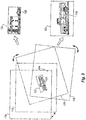
- the method also includes transforming the overlapping images 118 by performing frame averaging on the overlapping images 118 to produce an enhanced image 120 of the imaging area.
- Transforming the overlapping images 118 by performing frame averaging can be performed automatically at a coarse level to produce the enhanced image 120.
- the coarse level frame averaging can include determining what pixels from each overlapping image or frame overlap at a sub-pixel sampling distance, and averaging the overlapping pixels. This averaging increases the signal to noise ratio while at the same time the sensor continues to scan a larger area to maintain large area coverage while not increasing requirements on stabilization relative to traditional systems.
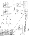
- Fig. 4 is a more detailed illustration of the relationship of frames within a scan and several scans.
- Fig. 4 shows how the frames from each scan overlap for three scans, wherein the ellipsis indicates any suitable number of scans can be used.
- This is an example where four frames overlap each ground point, e.g., frames 112, 113, 114, and the frame labeled Scan1Area1Frame1 all overlap a ground point; frames 121, 122, 123, and 124 all overlap another ground point and so forth. Then all of the first frames are pieced together at a course level, as indicated by the block 150 in Fig. 4 .
- course level images 152 are combined at a course level to form one average frame 154 of the entire area. This will have higher signal to noise ratio than any individual frame. Then the region of interest can be selected to further enhance with super resolution and frame averaging as indicated by reference character 156.
- the method can include transforming the overlapping images 118 by performing super resolution frame averaging on at least one portion 122 of the at overlapping images 118 to produce at least one super resolution image 124 of the imaging area wherein the at least one super resolution image 124 has a finer sampling than the at least one enhanced image 120.
- frame averaging to obtain super resolution image 124 includes increasing the sampling resolution or pixel count for area 122 to enhance detail or the like.
- Automatic object detection can be used to select the at least one portion 122 of the overlapping images 118 for producing the super resolution image 124 of a detected object 126.
- Using automatic object detection can include detecting moving objects within the overlapping images between scans for producing the super resolution image 124 of moving objects detected.
- user object detection can be used without departing from the scope of this disclosure.
- the moving object detection is shown schematically in greater detail.
- the time separation between frames within a scan maybe adequate as described above. However it may also be beneficial to overlap the scans, as indicated by reference character 158 in Fig. 5 , and use this larger time separation, i.e., the time separation from one scan to the next rather than from image to image within a single scan, to provide the moving target detection.
- the frames of each scan are pieced together at a course level as indicated by reference character 160.
- the combined course level images 162 are produced similar to those described with respect to Fig. 4 above. Combining these creates average frames 164. Since the object is moving, the registration includes additional steps beyond those shown in Fig.
- Transforming the overlapping images 118 can include identifying the region of interest, e.g., portion 122, gathering images from the overlapping images 118 that include the region of interest, performing compensation on the gathered images for optical distortion, compensating for orientation differences among the gathered images, selecting a master image, and registering the gathered images to the master image, wherein frame averaging is performed on the gathered images after they have been registered.
- This compensation and registration of images are indicated schematically in Fig. 3 by the double arrows indicating translations and rotation of images 118, and can also include warps or other transformations.
- Compensating for orientation differences can include using motion data and a motion model and/or a sensor model, e.g. from sensors on board aircraft 102 of Fig. 1 .
- a motion model can be useful, e.g., for estimating small movements like between the frames within a scan and can be adequate between scans as well.
- a sensor model could be used to project the pixel to the ground and ground back to the pixel in the other frames. This could be used when the time separation is more significant or the data is from another collection. Selecting a master image can include at least one of choosing a master image from among the gathered images or selecting a virtual master image to use as the master image for registration.
- a module 128 is operatively connected to the imaging sensor 110 to receive and the overlapping images 118 from the imaging sensor 110 and to transform the overlapping images 118 by performing frame averaging on the overlapping images 118 to produce at least one enhanced image of the imaging area as described above.
- the module 128 can include machine readable instructions configured to perform any of the image transformation methods described herein.
- frame averaging can be done while scanning, which provides increased coverage of a larger area and can simultaneously have a separate channel with a line array, for example, collecting imagery of the same area in one or more additional spectral bands.
- a beam splitter can be used to provide the separate channel for simultaneous collection of imagery from a second focal plane.
- aspects of the present embodiments may be embodied as a system, method or computer program product. Accordingly, aspects of the present embodiments may take the form of an entirely hardware embodiment, an entirely software embodiment (including firmware, resident software, micro-code, etc.) or an embodiment combining software and hardware aspects that may all generally be referred to herein as a "circuit,” “module” or “system.” Furthermore, aspects of the present disclosure may take the form of a computer program product embodied in one or more computer readable medium(s) having computer readable program code embodied thereon.
- the computer readable medium may be a computer readable signal medium or a computer readable storage medium.
- a computer readable storage medium may be, for example, but not limited to, an electronic, magnetic, optical, electromagnetic, infrared, or semiconductor system, apparatus, or device, or any suitable combination of the foregoing.
- a computer readable storage medium may be any tangible medium that can contain, or store a program for use by or in connection with an instruction execution system, apparatus, or device.
- a computer readable signal medium may include a propagated data signal with computer readable program code embodied therein, for example, in baseband or as part of a carrier wave. Such a propagated signal may take any of a variety of forms, including, but not limited to, electro-magnetic, optical, or any suitable combination thereof.
- a computer readable signal medium may be any computer readable medium that is not a computer readable storage medium and that can communicate, propagate, or transport a program for use by or in connection with an instruction execution system, apparatus, or device.
- Program code embodied on a computer readable medium may be transmitted using any appropriate medium, including but not limited to wireless, wireline, optical fiber cable, RF, etc., or any suitable combination of the foregoing.
- Computer program code for carrying out operations for aspects of the present disclosure may be written in any combination of one or more programming languages, including an object oriented programming language such as Java, Smalltalk, C++ or the like and conventional procedural programming languages, such as the "C" programming language or similar programming languages.
- the program code may execute entirely on the user's computer, partly on the user's computer, as a stand-alone software package, partly on the user's computer and partly on a remote computer or entirely on the remote computer or server.
- the remote computer may be connected to the user's computer through any type of network, including a local area network (LAN) or a wide area network (WAN), or the connection may be made to an external computer (for example, through the Internet using an Internet Service Provider).
- LAN local area network
- WAN wide area network
- Internet Service Provider for example, AT&T, MCI, Sprint, EarthLink, MSN, GTE, etc.
- These computer program instructions may also be stored in a computer readable medium that can direct a computer, other programmable data processing apparatus, or other devices to function in a particular manner, such that the instructions stored in the computer readable medium produce an article of manufacture including instructions which implement the function/act specified in the flowchart and/or block diagram block or blocks.
- the computer program instructions may also be loaded onto a computer, other programmable data processing apparatus, or other devices to cause a series of operational steps to be performed on the computer, other programmable apparatus or other devices to produce a computer implemented process such that the instructions which execute on the computer or other programmable apparatus provide processes for implementing the functions/acts specified in a flowchart and/or block diagram block or blocks.
Landscapes
- Engineering & Computer Science (AREA)
- Physics & Mathematics (AREA)
- General Physics & Mathematics (AREA)
- Multimedia (AREA)
- Theoretical Computer Science (AREA)
- Signal Processing (AREA)
- Remote Sensing (AREA)
- Radar, Positioning & Navigation (AREA)
- Computing Systems (AREA)
- Studio Devices (AREA)
- Geometry (AREA)
- Image Processing (AREA)
- Transforming Light Signals Into Electric Signals (AREA)
Applications Claiming Priority (1)
| Application Number | Priority Date | Filing Date | Title |
|---|---|---|---|
| US15/181,693 US10116863B2 (en) | 2016-06-14 | 2016-06-14 | Scanning with frame averaging |
Publications (3)
| Publication Number | Publication Date |
|---|---|
| EP3267150A2 true EP3267150A2 (de) | 2018-01-10 |
| EP3267150A3 EP3267150A3 (de) | 2018-04-18 |
| EP3267150B1 EP3267150B1 (de) | 2021-12-01 |
Family
ID=59294901
Family Applications (1)
| Application Number | Title | Priority Date | Filing Date |
|---|---|---|---|
| EP17175910.3A Active EP3267150B1 (de) | 2016-06-14 | 2017-06-14 | Abtastung mit bildmittelung |
Country Status (2)
| Country | Link |
|---|---|
| US (2) | US10116863B2 (de) |
| EP (1) | EP3267150B1 (de) |
Cited By (1)
| Publication number | Priority date | Publication date | Assignee | Title |
|---|---|---|---|---|
| CN108955642A (zh) * | 2018-05-07 | 2018-12-07 | 江苏师范大学 | 一种大幅面等效中心投影影像无缝拼接方法 |
Families Citing this family (6)
| Publication number | Priority date | Publication date | Assignee | Title |
|---|---|---|---|---|
| US11187909B2 (en) | 2017-01-31 | 2021-11-30 | Microsoft Technology Licensing, Llc | Text rendering by microshifting the display in a head mounted display |
| US10504397B2 (en) | 2017-01-31 | 2019-12-10 | Microsoft Technology Licensing, Llc | Curved narrowband illuminant display for head mounted display |
| US10354140B2 (en) * | 2017-01-31 | 2019-07-16 | Microsoft Technology Licensing, Llc | Video noise reduction for video augmented reality system |
| US10298840B2 (en) | 2017-01-31 | 2019-05-21 | Microsoft Technology Licensing, Llc | Foveated camera for video augmented reality and head mounted display |
| US11651474B2 (en) | 2020-11-04 | 2023-05-16 | Bae Systems Information And Electronic Systems Integration Inc. | Real-time super resolution at long standoff ranges |
| US12340598B2 (en) * | 2023-08-21 | 2025-06-24 | Telenav, Inc. | Compute system with visual front-end processing mechanism and method of operation thereof |
Family Cites Families (16)
| Publication number | Priority date | Publication date | Assignee | Title |
|---|---|---|---|---|
| DE19822249A1 (de) * | 1998-05-18 | 1999-11-25 | Honeywell Ag | Verfahren zur Bildabtastung |
| US6535650B1 (en) * | 1998-07-21 | 2003-03-18 | Intel Corporation | Creating high resolution images |
| US7103235B2 (en) | 2001-04-25 | 2006-09-05 | Lockheed Martin Corporation | Extended range image processing for electro-optical systems |
| US7308342B2 (en) * | 2004-01-23 | 2007-12-11 | Rafael Armament Development Authority Ltd. | Airborne reconnaissance system |
| JP2007206919A (ja) * | 2006-02-01 | 2007-08-16 | Sony Corp | 表示制御装置および方法、プログラム、並びに記録媒体 |
| US20090146953A1 (en) * | 2006-10-30 | 2009-06-11 | Imu Solutions, Inc. | Methods for processing data from accelerometer in anticipating real-time cursor control movements |
| DE102007001116A1 (de) * | 2007-01-04 | 2008-07-10 | Siemens Ag | Verfahren und Vorrichtung zur Registrierung von zumindest drei unterschiedlichen Bilddatensätzen eines Objektes |
| US9974509B2 (en) * | 2008-11-18 | 2018-05-22 | Sync-Rx Ltd. | Image super enhancement |
| KR101016656B1 (ko) * | 2009-05-19 | 2011-02-25 | 주식회사신도리코 | 스캔 기능을 구비한 화상 형성 장치 및 이의 스캔 방법 |
| US8577518B2 (en) * | 2009-05-27 | 2013-11-05 | American Aerospace Advisors, Inc. | Airborne right of way autonomous imager |
| JP6043187B2 (ja) * | 2010-03-12 | 2016-12-14 | コーニンクレッカ フィリップス エヌ ヴェKoninklijke Philips N.V. | 血管造影画像内の動きの視覚化 |
| US8970720B2 (en) * | 2010-07-26 | 2015-03-03 | Apple Inc. | Automatic digital camera photography mode selection |
| IL207590A (en) | 2010-08-12 | 2016-11-30 | Rafael Advanced Defense Systems Ltd | A method and system for increasing the size of the area scanned at a given time by an airborne electro-optical photo system |
| US8953012B2 (en) | 2012-02-13 | 2015-02-10 | Raytheon Company | Multi-plenoptic system with image stacking and method for wide field-of-regard high-resolution imaging |
| GB201313680D0 (en) * | 2013-07-31 | 2014-01-08 | Mbda Uk Ltd | Image processing |
| KR102251242B1 (ko) * | 2014-11-26 | 2021-05-12 | 삼성전자주식회사 | 컴퓨터 보조 진단 장치 및 방법 |
-
2016
- 2016-06-14 US US15/181,693 patent/US10116863B2/en active Active
-
2017
- 2017-06-14 EP EP17175910.3A patent/EP3267150B1/de active Active
-
2018
- 2018-10-11 US US16/157,690 patent/US10873700B2/en active Active
Non-Patent Citations (1)
| Title |
|---|
| None |
Cited By (2)
| Publication number | Priority date | Publication date | Assignee | Title |
|---|---|---|---|---|
| CN108955642A (zh) * | 2018-05-07 | 2018-12-07 | 江苏师范大学 | 一种大幅面等效中心投影影像无缝拼接方法 |
| CN108955642B (zh) * | 2018-05-07 | 2020-09-01 | 江苏师范大学 | 一种大幅面等效中心投影影像无缝拼接方法 |
Also Published As
| Publication number | Publication date |
|---|---|
| US20170359510A1 (en) | 2017-12-14 |
| US10873700B2 (en) | 2020-12-22 |
| EP3267150B1 (de) | 2021-12-01 |
| US20190098208A1 (en) | 2019-03-28 |
| US10116863B2 (en) | 2018-10-30 |
| EP3267150A3 (de) | 2018-04-18 |
Similar Documents
| Publication | Publication Date | Title |
|---|---|---|
| US10873700B2 (en) | Scanning with frame averaging | |
| CN111222395B (zh) | 目标检测方法、装置与电子设备 | |
| Ayhan et al. | A novel utilization of image registration techniques to process mastcam images in mars rover with applications to image fusion, pixel clustering, and anomaly detection | |
| CN110427917B (zh) | 用于检测关键点的方法和装置 | |
| US10578735B2 (en) | Multilook coherent change detection | |
| US11290704B2 (en) | Three dimensional scanning system and framework | |
| US10911680B2 (en) | Method and system of geolocation and attitude correction for mobile rolling shutter cameras | |
| JP6467776B2 (ja) | 測距システム、情報処理装置、情報処理方法及びプログラム | |
| JP2017117462A5 (de) | ||
| WO2012053521A1 (ja) | 光学情報処理装置、光学情報処理方法、光学情報処理システム、光学情報処理プログラム | |
| JP6233869B2 (ja) | 画像処理装置、画像処理装置の制御方法およびプログラム | |
| CN113950820B (zh) | 用于像素到像素信号扩散的校正 | |
| US8995793B1 (en) | Moving object super-resolution systems and methods | |
| EP3994516B1 (de) | System und verfahren zur erzeugung eines bildes | |
| US20170227642A1 (en) | Stereo range with lidar correction | |
| US10204405B2 (en) | Apparatus and method for parameterizing a plant | |
| Zhao et al. | Phenotyping of individual apple tree in modern orchard with novel smartphone-based heterogeneous binocular vision and YOLOv5s | |
| KR102235018B1 (ko) | 해상도가 다른 영상을 정합하는 장치 및 방법 | |
| CN116883235A (zh) | 一种面向分布式光电的图像拼接方法及装置 | |
| CN115018709B (zh) | 一种图像拼接岩壁重建的方法 | |
| US20190166314A1 (en) | Ortho-selfie distortion correction using multiple sources | |
| KR20190136363A (ko) | 원격탐사 성과물과 클라우드 기반 플랫폼과의 연계 시스템 | |
| CN119693991B (zh) | 基于光场相机的人脸识别方法及系统 | |
| EP4073754B1 (de) | Gemeinsame visuelle objektdetektion und objektkartierung zu einem 3d-modell | |
| Rivera et al. | Real-time Processing Solution for Single-Photon Sensitive Geiger-mode APD Based Airborne Lidar Systems |
Legal Events
| Date | Code | Title | Description |
|---|---|---|---|
| PUAI | Public reference made under article 153(3) epc to a published international application that has entered the european phase |
Free format text: ORIGINAL CODE: 0009012 |
|
| STAA | Information on the status of an ep patent application or granted ep patent |
Free format text: STATUS: THE APPLICATION HAS BEEN PUBLISHED |
|
| AK | Designated contracting states |
Kind code of ref document: A2 Designated state(s): AL AT BE BG CH CY CZ DE DK EE ES FI FR GB GR HR HU IE IS IT LI LT LU LV MC MK MT NL NO PL PT RO RS SE SI SK SM TR |
|
| AX | Request for extension of the european patent |
Extension state: BA ME |
|
| PUAL | Search report despatched |
Free format text: ORIGINAL CODE: 0009013 |
|
| AK | Designated contracting states |
Kind code of ref document: A3 Designated state(s): AL AT BE BG CH CY CZ DE DK EE ES FI FR GB GR HR HU IE IS IT LI LT LU LV MC MK MT NL NO PL PT RO RS SE SI SK SM TR |
|
| AX | Request for extension of the european patent |
Extension state: BA ME |
|
| RIC1 | Information provided on ipc code assigned before grant |
Ipc: G01C 11/02 20060101AFI20180312BHEP Ipc: G06T 7/38 20170101ALI20180312BHEP |
|
| STAA | Information on the status of an ep patent application or granted ep patent |
Free format text: STATUS: REQUEST FOR EXAMINATION WAS MADE |
|
| 17P | Request for examination filed |
Effective date: 20181018 |
|
| RBV | Designated contracting states (corrected) |
Designated state(s): AL AT BE BG CH CY CZ DE DK EE ES FI FR GB GR HR HU IE IS IT LI LT LU LV MC MK MT NL NO PL PT RO RS SE SI SK SM TR |
|
| STAA | Information on the status of an ep patent application or granted ep patent |
Free format text: STATUS: EXAMINATION IS IN PROGRESS |
|
| 17Q | First examination report despatched |
Effective date: 20191031 |
|
| GRAP | Despatch of communication of intention to grant a patent |
Free format text: ORIGINAL CODE: EPIDOSNIGR1 |
|
| STAA | Information on the status of an ep patent application or granted ep patent |
Free format text: STATUS: GRANT OF PATENT IS INTENDED |
|
| INTG | Intention to grant announced |
Effective date: 20210616 |
|
| GRAS | Grant fee paid |
Free format text: ORIGINAL CODE: EPIDOSNIGR3 |
|
| GRAA | (expected) grant |
Free format text: ORIGINAL CODE: 0009210 |
|
| STAA | Information on the status of an ep patent application or granted ep patent |
Free format text: STATUS: THE PATENT HAS BEEN GRANTED |
|
| AK | Designated contracting states |
Kind code of ref document: B1 Designated state(s): AL AT BE BG CH CY CZ DE DK EE ES FI FR GB GR HR HU IE IS IT LI LT LU LV MC MK MT NL NO PL PT RO RS SE SI SK SM TR |
|
| REG | Reference to a national code |
Ref country code: GB Ref legal event code: FG4D |
|
| REG | Reference to a national code |
Ref country code: AT Ref legal event code: REF Ref document number: 1452164 Country of ref document: AT Kind code of ref document: T Effective date: 20211215 Ref country code: CH Ref legal event code: EP |
|
| REG | Reference to a national code |
Ref country code: IE Ref legal event code: FG4D |
|
| REG | Reference to a national code |
Ref country code: DE Ref legal event code: R096 Ref document number: 602017050054 Country of ref document: DE |
|
| REG | Reference to a national code |
Ref country code: LT Ref legal event code: MG9D |
|
| REG | Reference to a national code |
Ref country code: NL Ref legal event code: MP Effective date: 20211201 |
|
| REG | Reference to a national code |
Ref country code: AT Ref legal event code: MK05 Ref document number: 1452164 Country of ref document: AT Kind code of ref document: T Effective date: 20211201 |
|
| PG25 | Lapsed in a contracting state [announced via postgrant information from national office to epo] |
Ref country code: RS Free format text: LAPSE BECAUSE OF FAILURE TO SUBMIT A TRANSLATION OF THE DESCRIPTION OR TO PAY THE FEE WITHIN THE PRESCRIBED TIME-LIMIT Effective date: 20211201 Ref country code: LT Free format text: LAPSE BECAUSE OF FAILURE TO SUBMIT A TRANSLATION OF THE DESCRIPTION OR TO PAY THE FEE WITHIN THE PRESCRIBED TIME-LIMIT Effective date: 20211201 Ref country code: FI Free format text: LAPSE BECAUSE OF FAILURE TO SUBMIT A TRANSLATION OF THE DESCRIPTION OR TO PAY THE FEE WITHIN THE PRESCRIBED TIME-LIMIT Effective date: 20211201 Ref country code: BG Free format text: LAPSE BECAUSE OF FAILURE TO SUBMIT A TRANSLATION OF THE DESCRIPTION OR TO PAY THE FEE WITHIN THE PRESCRIBED TIME-LIMIT Effective date: 20220301 Ref country code: AT Free format text: LAPSE BECAUSE OF FAILURE TO SUBMIT A TRANSLATION OF THE DESCRIPTION OR TO PAY THE FEE WITHIN THE PRESCRIBED TIME-LIMIT Effective date: 20211201 |
|
| PG25 | Lapsed in a contracting state [announced via postgrant information from national office to epo] |
Ref country code: SE Free format text: LAPSE BECAUSE OF FAILURE TO SUBMIT A TRANSLATION OF THE DESCRIPTION OR TO PAY THE FEE WITHIN THE PRESCRIBED TIME-LIMIT Effective date: 20211201 Ref country code: PL Free format text: LAPSE BECAUSE OF FAILURE TO SUBMIT A TRANSLATION OF THE DESCRIPTION OR TO PAY THE FEE WITHIN THE PRESCRIBED TIME-LIMIT Effective date: 20211201 Ref country code: NO Free format text: LAPSE BECAUSE OF FAILURE TO SUBMIT A TRANSLATION OF THE DESCRIPTION OR TO PAY THE FEE WITHIN THE PRESCRIBED TIME-LIMIT Effective date: 20220301 Ref country code: LV Free format text: LAPSE BECAUSE OF FAILURE TO SUBMIT A TRANSLATION OF THE DESCRIPTION OR TO PAY THE FEE WITHIN THE PRESCRIBED TIME-LIMIT Effective date: 20211201 Ref country code: HR Free format text: LAPSE BECAUSE OF FAILURE TO SUBMIT A TRANSLATION OF THE DESCRIPTION OR TO PAY THE FEE WITHIN THE PRESCRIBED TIME-LIMIT Effective date: 20211201 Ref country code: GR Free format text: LAPSE BECAUSE OF FAILURE TO SUBMIT A TRANSLATION OF THE DESCRIPTION OR TO PAY THE FEE WITHIN THE PRESCRIBED TIME-LIMIT Effective date: 20220302 |
|
| PG25 | Lapsed in a contracting state [announced via postgrant information from national office to epo] |
Ref country code: NL Free format text: LAPSE BECAUSE OF FAILURE TO SUBMIT A TRANSLATION OF THE DESCRIPTION OR TO PAY THE FEE WITHIN THE PRESCRIBED TIME-LIMIT Effective date: 20211201 |
|
| PG25 | Lapsed in a contracting state [announced via postgrant information from national office to epo] |
Ref country code: SM Free format text: LAPSE BECAUSE OF FAILURE TO SUBMIT A TRANSLATION OF THE DESCRIPTION OR TO PAY THE FEE WITHIN THE PRESCRIBED TIME-LIMIT Effective date: 20211201 Ref country code: SK Free format text: LAPSE BECAUSE OF FAILURE TO SUBMIT A TRANSLATION OF THE DESCRIPTION OR TO PAY THE FEE WITHIN THE PRESCRIBED TIME-LIMIT Effective date: 20211201 Ref country code: RO Free format text: LAPSE BECAUSE OF FAILURE TO SUBMIT A TRANSLATION OF THE DESCRIPTION OR TO PAY THE FEE WITHIN THE PRESCRIBED TIME-LIMIT Effective date: 20211201 Ref country code: PT Free format text: LAPSE BECAUSE OF FAILURE TO SUBMIT A TRANSLATION OF THE DESCRIPTION OR TO PAY THE FEE WITHIN THE PRESCRIBED TIME-LIMIT Effective date: 20220401 Ref country code: ES Free format text: LAPSE BECAUSE OF FAILURE TO SUBMIT A TRANSLATION OF THE DESCRIPTION OR TO PAY THE FEE WITHIN THE PRESCRIBED TIME-LIMIT Effective date: 20211201 Ref country code: EE Free format text: LAPSE BECAUSE OF FAILURE TO SUBMIT A TRANSLATION OF THE DESCRIPTION OR TO PAY THE FEE WITHIN THE PRESCRIBED TIME-LIMIT Effective date: 20211201 Ref country code: CZ Free format text: LAPSE BECAUSE OF FAILURE TO SUBMIT A TRANSLATION OF THE DESCRIPTION OR TO PAY THE FEE WITHIN THE PRESCRIBED TIME-LIMIT Effective date: 20211201 |
|
| REG | Reference to a national code |
Ref country code: DE Ref legal event code: R097 Ref document number: 602017050054 Country of ref document: DE |
|
| PG25 | Lapsed in a contracting state [announced via postgrant information from national office to epo] |
Ref country code: IS Free format text: LAPSE BECAUSE OF FAILURE TO SUBMIT A TRANSLATION OF THE DESCRIPTION OR TO PAY THE FEE WITHIN THE PRESCRIBED TIME-LIMIT Effective date: 20220401 |
|
| PLBE | No opposition filed within time limit |
Free format text: ORIGINAL CODE: 0009261 |
|
| STAA | Information on the status of an ep patent application or granted ep patent |
Free format text: STATUS: NO OPPOSITION FILED WITHIN TIME LIMIT |
|
| PG25 | Lapsed in a contracting state [announced via postgrant information from national office to epo] |
Ref country code: DK Free format text: LAPSE BECAUSE OF FAILURE TO SUBMIT A TRANSLATION OF THE DESCRIPTION OR TO PAY THE FEE WITHIN THE PRESCRIBED TIME-LIMIT Effective date: 20211201 Ref country code: AL Free format text: LAPSE BECAUSE OF FAILURE TO SUBMIT A TRANSLATION OF THE DESCRIPTION OR TO PAY THE FEE WITHIN THE PRESCRIBED TIME-LIMIT Effective date: 20211201 |
|
| 26N | No opposition filed |
Effective date: 20220902 |
|
| PG25 | Lapsed in a contracting state [announced via postgrant information from national office to epo] |
Ref country code: SI Free format text: LAPSE BECAUSE OF FAILURE TO SUBMIT A TRANSLATION OF THE DESCRIPTION OR TO PAY THE FEE WITHIN THE PRESCRIBED TIME-LIMIT Effective date: 20211201 |
|
| REG | Reference to a national code |
Ref country code: DE Ref legal event code: R119 Ref document number: 602017050054 Country of ref document: DE |
|
| PG25 | Lapsed in a contracting state [announced via postgrant information from national office to epo] |
Ref country code: MC Free format text: LAPSE BECAUSE OF FAILURE TO SUBMIT A TRANSLATION OF THE DESCRIPTION OR TO PAY THE FEE WITHIN THE PRESCRIBED TIME-LIMIT Effective date: 20211201 |
|
| REG | Reference to a national code |
Ref country code: CH Ref legal event code: PL |
|
| REG | Reference to a national code |
Ref country code: BE Ref legal event code: MM Effective date: 20220630 |
|
| PG25 | Lapsed in a contracting state [announced via postgrant information from national office to epo] |
Ref country code: LU Free format text: LAPSE BECAUSE OF NON-PAYMENT OF DUE FEES Effective date: 20220614 Ref country code: LI Free format text: LAPSE BECAUSE OF NON-PAYMENT OF DUE FEES Effective date: 20220630 Ref country code: IE Free format text: LAPSE BECAUSE OF NON-PAYMENT OF DUE FEES Effective date: 20220614 Ref country code: CH Free format text: LAPSE BECAUSE OF NON-PAYMENT OF DUE FEES Effective date: 20220630 |
|
| PG25 | Lapsed in a contracting state [announced via postgrant information from national office to epo] |
Ref country code: IT Free format text: LAPSE BECAUSE OF FAILURE TO SUBMIT A TRANSLATION OF THE DESCRIPTION OR TO PAY THE FEE WITHIN THE PRESCRIBED TIME-LIMIT Effective date: 20211201 Ref country code: DE Free format text: LAPSE BECAUSE OF NON-PAYMENT OF DUE FEES Effective date: 20230103 Ref country code: BE Free format text: LAPSE BECAUSE OF NON-PAYMENT OF DUE FEES Effective date: 20220630 |
|
| P01 | Opt-out of the competence of the unified patent court (upc) registered |
Effective date: 20230522 |
|
| PG25 | Lapsed in a contracting state [announced via postgrant information from national office to epo] |
Ref country code: HU Free format text: LAPSE BECAUSE OF FAILURE TO SUBMIT A TRANSLATION OF THE DESCRIPTION OR TO PAY THE FEE WITHIN THE PRESCRIBED TIME-LIMIT; INVALID AB INITIO Effective date: 20170614 |
|
| PG25 | Lapsed in a contracting state [announced via postgrant information from national office to epo] |
Ref country code: MK Free format text: LAPSE BECAUSE OF FAILURE TO SUBMIT A TRANSLATION OF THE DESCRIPTION OR TO PAY THE FEE WITHIN THE PRESCRIBED TIME-LIMIT Effective date: 20211201 Ref country code: CY Free format text: LAPSE BECAUSE OF FAILURE TO SUBMIT A TRANSLATION OF THE DESCRIPTION OR TO PAY THE FEE WITHIN THE PRESCRIBED TIME-LIMIT Effective date: 20211201 |
|
| PG25 | Lapsed in a contracting state [announced via postgrant information from national office to epo] |
Ref country code: TR Free format text: LAPSE BECAUSE OF FAILURE TO SUBMIT A TRANSLATION OF THE DESCRIPTION OR TO PAY THE FEE WITHIN THE PRESCRIBED TIME-LIMIT Effective date: 20211201 |
|
| PG25 | Lapsed in a contracting state [announced via postgrant information from national office to epo] |
Ref country code: MT Free format text: LAPSE BECAUSE OF FAILURE TO SUBMIT A TRANSLATION OF THE DESCRIPTION OR TO PAY THE FEE WITHIN THE PRESCRIBED TIME-LIMIT Effective date: 20211201 |
|
| PGFP | Annual fee paid to national office [announced via postgrant information from national office to epo] |
Ref country code: GB Payment date: 20250520 Year of fee payment: 9 |
|
| PGFP | Annual fee paid to national office [announced via postgrant information from national office to epo] |
Ref country code: FR Payment date: 20250520 Year of fee payment: 9 |