EP3266900B1 - Molten al-zn-mg-si-plated steel sheet - Google Patents
Molten al-zn-mg-si-plated steel sheet Download PDFInfo
- Publication number
- EP3266900B1 EP3266900B1 EP16759061.1A EP16759061A EP3266900B1 EP 3266900 B1 EP3266900 B1 EP 3266900B1 EP 16759061 A EP16759061 A EP 16759061A EP 3266900 B1 EP3266900 B1 EP 3266900B1
- Authority
- EP
- European Patent Office
- Prior art keywords
- hot
- mass
- dip
- steel sheet
- coating
- Prior art date
- Legal status (The legal status is an assumption and is not a legal conclusion. Google has not performed a legal analysis and makes no representation as to the accuracy of the status listed.)
- Active
Links
- 229910000831 Steel Inorganic materials 0.000 title claims description 134
- 239000010959 steel Substances 0.000 title claims description 134
- 238000003618 dip coating Methods 0.000 claims description 125
- 229910019752 Mg2Si Inorganic materials 0.000 claims description 112
- 229910019064 Mg-Si Inorganic materials 0.000 claims description 66
- 229910019406 Mg—Si Inorganic materials 0.000 claims description 66
- 229910045601 alloy Inorganic materials 0.000 claims description 56
- 239000000956 alloy Substances 0.000 claims description 56
- 210000001787 dendrite Anatomy 0.000 claims description 38
- 238000000034 method Methods 0.000 claims description 35
- 239000011856 silicon-based particle Substances 0.000 claims description 11
- 229910052804 chromium Inorganic materials 0.000 claims description 8
- 229910052748 manganese Inorganic materials 0.000 claims description 8
- 229910052750 molybdenum Inorganic materials 0.000 claims description 8
- 229910052759 nickel Inorganic materials 0.000 claims description 8
- 229910052712 strontium Inorganic materials 0.000 claims description 8
- 229910052719 titanium Inorganic materials 0.000 claims description 8
- 229910052720 vanadium Inorganic materials 0.000 claims description 8
- 239000012535 impurity Substances 0.000 claims description 5
- 238000002441 X-ray diffraction Methods 0.000 claims description 4
- 238000005260 corrosion Methods 0.000 description 146
- 230000007797 corrosion Effects 0.000 description 144
- 239000010410 layer Substances 0.000 description 94
- 238000000576 coating method Methods 0.000 description 81
- 239000011248 coating agent Substances 0.000 description 78
- 238000001816 cooling Methods 0.000 description 40
- 230000015572 biosynthetic process Effects 0.000 description 29
- JEIPFZHSYJVQDO-UHFFFAOYSA-N iron(III) oxide Inorganic materials O=[Fe]O[Fe]=O JEIPFZHSYJVQDO-UHFFFAOYSA-N 0.000 description 26
- 239000000047 product Substances 0.000 description 26
- 239000011701 zinc Substances 0.000 description 24
- 229910018137 Al-Zn Inorganic materials 0.000 description 23
- 229910018573 Al—Zn Inorganic materials 0.000 description 23
- 230000000052 comparative effect Effects 0.000 description 21
- 239000000203 mixture Substances 0.000 description 21
- 238000011156 evaluation Methods 0.000 description 18
- 238000004519 manufacturing process Methods 0.000 description 17
- 239000000126 substance Substances 0.000 description 16
- 238000006243 chemical reaction Methods 0.000 description 13
- 230000000694 effects Effects 0.000 description 12
- 239000006185 dispersion Substances 0.000 description 10
- 229910052710 silicon Inorganic materials 0.000 description 10
- 238000012360 testing method Methods 0.000 description 9
- 238000005452 bending Methods 0.000 description 8
- 229910000765 intermetallic Inorganic materials 0.000 description 8
- 229910052749 magnesium Inorganic materials 0.000 description 8
- 238000005507 spraying Methods 0.000 description 8
- 150000001875 compounds Chemical class 0.000 description 7
- 238000001035 drying Methods 0.000 description 7
- 229910052782 aluminium Inorganic materials 0.000 description 6
- 229910052791 calcium Inorganic materials 0.000 description 6
- 238000007796 conventional method Methods 0.000 description 6
- 125000004122 cyclic group Chemical group 0.000 description 6
- 230000006872 improvement Effects 0.000 description 6
- 239000000463 material Substances 0.000 description 6
- 230000008520 organization Effects 0.000 description 6
- 238000001556 precipitation Methods 0.000 description 6
- 238000007711 solidification Methods 0.000 description 6
- 230000008023 solidification Effects 0.000 description 6
- 238000009736 wetting Methods 0.000 description 6
- 239000012141 concentrate Substances 0.000 description 5
- 238000007739 conversion coating Methods 0.000 description 5
- 238000004090 dissolution Methods 0.000 description 5
- 238000009826 distribution Methods 0.000 description 5
- 238000004070 electrodeposition Methods 0.000 description 5
- 230000008569 process Effects 0.000 description 5
- 150000003839 salts Chemical class 0.000 description 5
- LRXTYHSAJDENHV-UHFFFAOYSA-H zinc phosphate Chemical compound [Zn+2].[Zn+2].[Zn+2].[O-]P([O-])([O-])=O.[O-]P([O-])([O-])=O LRXTYHSAJDENHV-UHFFFAOYSA-H 0.000 description 5
- 229910000165 zinc phosphate Inorganic materials 0.000 description 5
- 239000011247 coating layer Substances 0.000 description 4
- 239000007788 liquid Substances 0.000 description 4
- 231100000241 scar Toxicity 0.000 description 4
- 229910052725 zinc Inorganic materials 0.000 description 4
- 229910018125 Al-Si Inorganic materials 0.000 description 3
- 229910018520 Al—Si Inorganic materials 0.000 description 3
- 238000004458 analytical method Methods 0.000 description 3
- 238000005246 galvanizing Methods 0.000 description 3
- 238000010438 heat treatment Methods 0.000 description 3
- 229910001335 Galvanized steel Inorganic materials 0.000 description 2
- 229910019641 Mg2 Si Inorganic materials 0.000 description 2
- 229910017708 MgZn2 Inorganic materials 0.000 description 2
- 229910000676 Si alloy Inorganic materials 0.000 description 2
- 239000002253 acid Substances 0.000 description 2
- 238000005275 alloying Methods 0.000 description 2
- 238000000137 annealing Methods 0.000 description 2
- 239000004566 building material Substances 0.000 description 2
- 239000003795 chemical substances by application Substances 0.000 description 2
- 238000004532 chromating Methods 0.000 description 2
- 239000010960 cold rolled steel Substances 0.000 description 2
- 230000007423 decrease Effects 0.000 description 2
- 238000002149 energy-dispersive X-ray emission spectroscopy Methods 0.000 description 2
- 239000008397 galvanized steel Substances 0.000 description 2
- 238000007654 immersion Methods 0.000 description 2
- 238000009616 inductively coupled plasma Methods 0.000 description 2
- 230000002401 inhibitory effect Effects 0.000 description 2
- 230000005764 inhibitory process Effects 0.000 description 2
- 230000007774 longterm Effects 0.000 description 2
- 238000005259 measurement Methods 0.000 description 2
- 229910052751 metal Inorganic materials 0.000 description 2
- 239000002184 metal Substances 0.000 description 2
- 150000002739 metals Chemical class 0.000 description 2
- 239000002244 precipitate Substances 0.000 description 2
- 238000011160 research Methods 0.000 description 2
- 230000004044 response Effects 0.000 description 2
- 229910000838 Al alloy Inorganic materials 0.000 description 1
- 229920000877 Melamine resin Polymers 0.000 description 1
- -1 Mg2Si Chemical class 0.000 description 1
- 229910019743 Mg2Sn Inorganic materials 0.000 description 1
- HCHKCACWOHOZIP-UHFFFAOYSA-N Zinc Chemical compound [Zn] HCHKCACWOHOZIP-UHFFFAOYSA-N 0.000 description 1
- 230000001133 acceleration Effects 0.000 description 1
- XAGFODPZIPBFFR-UHFFFAOYSA-N aluminium Chemical compound [Al] XAGFODPZIPBFFR-UHFFFAOYSA-N 0.000 description 1
- PNEYBMLMFCGWSK-UHFFFAOYSA-N aluminium oxide Inorganic materials [O-2].[O-2].[O-2].[Al+3].[Al+3] PNEYBMLMFCGWSK-UHFFFAOYSA-N 0.000 description 1
- 230000004888 barrier function Effects 0.000 description 1
- 230000005540 biological transmission Effects 0.000 description 1
- 238000005266 casting Methods 0.000 description 1
- 230000008859 change Effects 0.000 description 1
- 239000008199 coating composition Substances 0.000 description 1
- 238000005097 cold rolling Methods 0.000 description 1
- 238000010276 construction Methods 0.000 description 1
- 229910052593 corundum Inorganic materials 0.000 description 1
- 238000005336 cracking Methods 0.000 description 1
- 238000005237 degreasing agent Methods 0.000 description 1
- 239000013527 degreasing agent Substances 0.000 description 1
- 230000001934 delay Effects 0.000 description 1
- 230000006866 deterioration Effects 0.000 description 1
- 238000011161 development Methods 0.000 description 1
- 238000010894 electron beam technology Methods 0.000 description 1
- 238000010828 elution Methods 0.000 description 1
- 238000004993 emission spectroscopy Methods 0.000 description 1
- 239000003822 epoxy resin Substances 0.000 description 1
- 238000005530 etching Methods 0.000 description 1
- 229910052731 fluorine Inorganic materials 0.000 description 1
- 239000011737 fluorine Substances 0.000 description 1
- 238000007602 hot air drying Methods 0.000 description 1
- 238000003384 imaging method Methods 0.000 description 1
- 230000006698 induction Effects 0.000 description 1
- 238000013507 mapping Methods 0.000 description 1
- JDSHMPZPIAZGSV-UHFFFAOYSA-N melamine Chemical compound NC1=NC(N)=NC(N)=N1 JDSHMPZPIAZGSV-UHFFFAOYSA-N 0.000 description 1
- 230000003287 optical effect Effects 0.000 description 1
- 230000035515 penetration Effects 0.000 description 1
- 238000005554 pickling Methods 0.000 description 1
- 238000005498 polishing Methods 0.000 description 1
- 229920000647 polyepoxide Polymers 0.000 description 1
- 229920000728 polyester Polymers 0.000 description 1
- 238000012545 processing Methods 0.000 description 1
- 230000001681 protective effect Effects 0.000 description 1
- 230000009467 reduction Effects 0.000 description 1
- 229920005989 resin Polymers 0.000 description 1
- 239000011347 resin Substances 0.000 description 1
- 230000037390 scarring Effects 0.000 description 1
- 239000010703 silicon Substances 0.000 description 1
- 239000002356 single layer Substances 0.000 description 1
- 239000000758 substrate Substances 0.000 description 1
- 229920002803 thermoplastic polyurethane Polymers 0.000 description 1
- 229910052718 tin Inorganic materials 0.000 description 1
- 238000005406 washing Methods 0.000 description 1
- XLYOFNOQVPJJNP-UHFFFAOYSA-N water Substances O XLYOFNOQVPJJNP-UHFFFAOYSA-N 0.000 description 1
- 238000004736 wide-angle X-ray diffraction Methods 0.000 description 1
- 229910001845 yogo sapphire Inorganic materials 0.000 description 1
Images

Classifications
-
- C—CHEMISTRY; METALLURGY
- C23—COATING METALLIC MATERIAL; COATING MATERIAL WITH METALLIC MATERIAL; CHEMICAL SURFACE TREATMENT; DIFFUSION TREATMENT OF METALLIC MATERIAL; COATING BY VACUUM EVAPORATION, BY SPUTTERING, BY ION IMPLANTATION OR BY CHEMICAL VAPOUR DEPOSITION, IN GENERAL; INHIBITING CORROSION OF METALLIC MATERIAL OR INCRUSTATION IN GENERAL
- C23C—COATING METALLIC MATERIAL; COATING MATERIAL WITH METALLIC MATERIAL; SURFACE TREATMENT OF METALLIC MATERIAL BY DIFFUSION INTO THE SURFACE, BY CHEMICAL CONVERSION OR SUBSTITUTION; COATING BY VACUUM EVAPORATION, BY SPUTTERING, BY ION IMPLANTATION OR BY CHEMICAL VAPOUR DEPOSITION, IN GENERAL
- C23C2/00—Hot-dipping or immersion processes for applying the coating material in the molten state without affecting the shape; Apparatus therefor
- C23C2/04—Hot-dipping or immersion processes for applying the coating material in the molten state without affecting the shape; Apparatus therefor characterised by the coating material
- C23C2/06—Zinc or cadmium or alloys based thereon
-
- C—CHEMISTRY; METALLURGY
- C23—COATING METALLIC MATERIAL; COATING MATERIAL WITH METALLIC MATERIAL; CHEMICAL SURFACE TREATMENT; DIFFUSION TREATMENT OF METALLIC MATERIAL; COATING BY VACUUM EVAPORATION, BY SPUTTERING, BY ION IMPLANTATION OR BY CHEMICAL VAPOUR DEPOSITION, IN GENERAL; INHIBITING CORROSION OF METALLIC MATERIAL OR INCRUSTATION IN GENERAL
- C23C—COATING METALLIC MATERIAL; COATING MATERIAL WITH METALLIC MATERIAL; SURFACE TREATMENT OF METALLIC MATERIAL BY DIFFUSION INTO THE SURFACE, BY CHEMICAL CONVERSION OR SUBSTITUTION; COATING BY VACUUM EVAPORATION, BY SPUTTERING, BY ION IMPLANTATION OR BY CHEMICAL VAPOUR DEPOSITION, IN GENERAL
- C23C2/00—Hot-dipping or immersion processes for applying the coating material in the molten state without affecting the shape; Apparatus therefor
- C23C2/04—Hot-dipping or immersion processes for applying the coating material in the molten state without affecting the shape; Apparatus therefor characterised by the coating material
- C23C2/12—Aluminium or alloys based thereon
-
- C—CHEMISTRY; METALLURGY
- C22—METALLURGY; FERROUS OR NON-FERROUS ALLOYS; TREATMENT OF ALLOYS OR NON-FERROUS METALS
- C22C—ALLOYS
- C22C18/00—Alloys based on zinc
- C22C18/04—Alloys based on zinc with aluminium as the next major constituent
-
- C—CHEMISTRY; METALLURGY
- C22—METALLURGY; FERROUS OR NON-FERROUS ALLOYS; TREATMENT OF ALLOYS OR NON-FERROUS METALS
- C22C—ALLOYS
- C22C21/00—Alloys based on aluminium
- C22C21/10—Alloys based on aluminium with zinc as the next major constituent
-
- C—CHEMISTRY; METALLURGY
- C22—METALLURGY; FERROUS OR NON-FERROUS ALLOYS; TREATMENT OF ALLOYS OR NON-FERROUS METALS
- C22C—ALLOYS
- C22C30/00—Alloys containing less than 50% by weight of each constituent
- C22C30/06—Alloys containing less than 50% by weight of each constituent containing zinc
-
- C—CHEMISTRY; METALLURGY
- C23—COATING METALLIC MATERIAL; COATING MATERIAL WITH METALLIC MATERIAL; CHEMICAL SURFACE TREATMENT; DIFFUSION TREATMENT OF METALLIC MATERIAL; COATING BY VACUUM EVAPORATION, BY SPUTTERING, BY ION IMPLANTATION OR BY CHEMICAL VAPOUR DEPOSITION, IN GENERAL; INHIBITING CORROSION OF METALLIC MATERIAL OR INCRUSTATION IN GENERAL
- C23C—COATING METALLIC MATERIAL; COATING MATERIAL WITH METALLIC MATERIAL; SURFACE TREATMENT OF METALLIC MATERIAL BY DIFFUSION INTO THE SURFACE, BY CHEMICAL CONVERSION OR SUBSTITUTION; COATING BY VACUUM EVAPORATION, BY SPUTTERING, BY ION IMPLANTATION OR BY CHEMICAL VAPOUR DEPOSITION, IN GENERAL
- C23C2/00—Hot-dipping or immersion processes for applying the coating material in the molten state without affecting the shape; Apparatus therefor
- C23C2/26—After-treatment
- C23C2/28—Thermal after-treatment, e.g. treatment in oil bath
- C23C2/29—Cooling or quenching
-
- C—CHEMISTRY; METALLURGY
- C23—COATING METALLIC MATERIAL; COATING MATERIAL WITH METALLIC MATERIAL; CHEMICAL SURFACE TREATMENT; DIFFUSION TREATMENT OF METALLIC MATERIAL; COATING BY VACUUM EVAPORATION, BY SPUTTERING, BY ION IMPLANTATION OR BY CHEMICAL VAPOUR DEPOSITION, IN GENERAL; INHIBITING CORROSION OF METALLIC MATERIAL OR INCRUSTATION IN GENERAL
- C23C—COATING METALLIC MATERIAL; COATING MATERIAL WITH METALLIC MATERIAL; SURFACE TREATMENT OF METALLIC MATERIAL BY DIFFUSION INTO THE SURFACE, BY CHEMICAL CONVERSION OR SUBSTITUTION; COATING BY VACUUM EVAPORATION, BY SPUTTERING, BY ION IMPLANTATION OR BY CHEMICAL VAPOUR DEPOSITION, IN GENERAL
- C23C2/00—Hot-dipping or immersion processes for applying the coating material in the molten state without affecting the shape; Apparatus therefor
- C23C2/34—Hot-dipping or immersion processes for applying the coating material in the molten state without affecting the shape; Apparatus therefor characterised by the shape of the material to be treated
- C23C2/36—Elongated material
- C23C2/40—Plates; Strips
-
- C—CHEMISTRY; METALLURGY
- C23—COATING METALLIC MATERIAL; COATING MATERIAL WITH METALLIC MATERIAL; CHEMICAL SURFACE TREATMENT; DIFFUSION TREATMENT OF METALLIC MATERIAL; COATING BY VACUUM EVAPORATION, BY SPUTTERING, BY ION IMPLANTATION OR BY CHEMICAL VAPOUR DEPOSITION, IN GENERAL; INHIBITING CORROSION OF METALLIC MATERIAL OR INCRUSTATION IN GENERAL
- C23C—COATING METALLIC MATERIAL; COATING MATERIAL WITH METALLIC MATERIAL; SURFACE TREATMENT OF METALLIC MATERIAL BY DIFFUSION INTO THE SURFACE, BY CHEMICAL CONVERSION OR SUBSTITUTION; COATING BY VACUUM EVAPORATION, BY SPUTTERING, BY ION IMPLANTATION OR BY CHEMICAL VAPOUR DEPOSITION, IN GENERAL
- C23C28/00—Coating for obtaining at least two superposed coatings either by methods not provided for in a single one of groups C23C2/00 - C23C26/00 or by combinations of methods provided for in subclasses C23C and C25C or C25D
- C23C28/02—Coating for obtaining at least two superposed coatings either by methods not provided for in a single one of groups C23C2/00 - C23C26/00 or by combinations of methods provided for in subclasses C23C and C25C or C25D only coatings only including layers of metallic material
- C23C28/023—Coating for obtaining at least two superposed coatings either by methods not provided for in a single one of groups C23C2/00 - C23C26/00 or by combinations of methods provided for in subclasses C23C and C25C or C25D only coatings only including layers of metallic material only coatings of metal elements only
Definitions
- This disclosure relates to a hot-dip Al-Zn-Mg-Si coated steel sheet having good corrosion resistance in flat parts and edge parts, and also having excellent corrosion resistance in worked parts.
- Hot-dip Al-Zn alloy-coated steel sheets have both the sacrificial protection of Zn and the high corrosion resistance of Al, and thus rank highly in terms of corrosion resistance among hot-dip galvanized steel sheets.
- PTL I JP S46-7161 B discloses a hot-dip Al-Zn alloy-coated steel sheet in which the hot-dip coating contains from 25 mass% to 75 mass% of Al. Due to their excellent corrosion resistance, hot-dip Al-Zn alloy-coated steel sheets have been the subject of increased demand in recent years, particularly in the field of building materials for roofs, walls, and the like that undergo long-term exposure to outdoor environments, and the field of civil engineering and construction for guardrails, wiring, piping, sound proof walls, and the like.
- the hot-dip coating of a hot-dip Al-Zn alloy-coated steel sheet includes a main layer and an alloy layer present at an interface of the main layer with a base steel sheet.
- the main layer is mainly composed of regions where Zn is contained in a supersaturated state and Al is solidified by dendrite solidification ( ⁇ -Al phase dendritic regions), and remaining interdendritic regions between the dendrites, and has a structure with the ⁇ -Al phase stacked in multiple layers in the thickness direction of the hot-dip coating. Due to such characteristic hot-dip coating structure, the corrosion path from the surface becomes complex, making it difficult for corrosion to reach the base steel sheet. Therefore, better corrosion resistance can be achieved with a hot-dip Al-Zn alloy-coated steel sheet than with a hot-dip galvanized steel sheet having the same hot-dip coating thickness.
- PTL 2 JP 5020228 B discloses an Al-Zn-Mg-Si coated steel sheet in which the hot-dip coating contains a Mg-containing Al-Zn-Si alloy.
- the Al-Zn-Si alloy contains from 45 wt% to 60 wt% of aluminum, from 37 wt% to 46 wt% of zinc, and from 1.2 wt% to 2.3 wt% of silicon, and has a Mg concentration of from I wt% to 5 wt%.
- PTL 3 JP 5000039 B discloses a surface treated steel material having an Al alloy coating containing, by mass%, from 2% to 10% of Mg, from 0.01% to 10% of Ca, and from 3% to 15% of Si, the balance being Al and incidental impurities, and having a Mg/Si mass ratio in a specific range.
- Hot-dip Al-Zn alloy-coated steel sheets that are to be used in the automotive field, and particularly those that are to be used for outer panels, are typically supplied to automobile manufacturers and the like in a state in which production up to hot-dip coating in a continuous galvanizing line (CGL) has been completed. After being worked into the shape of a panel component, the hot-dip Al-Zn alloy-coated steel sheet is typically subjected to chemical conversion treatment, and also general coating for automobile use by electrodeposition coating, intermediate coating and top coating.
- CGL continuous galvanizing line
- PTL 4 JP 2002-12959 A ), for example, discloses a hot-dip Al-Zn alloy-coated steel sheet in which the formation of red rust from edge surfaces of the steel sheet is improved by adding Mg, Sn, or the like to the hot-dip coating composition in order that a Mg compound such as Mg 2 Si, MgZn 2 , Mg 2 Sn, or the like is formed in the hot-dip coating layer.
- hot-dip Al-Zn alloy-coated steel sheets are often used in the field of building materials for roofs, walls, and the like that undergo long-term exposure to outdoor environments. Therefore, there is demand for the development of hot-dip Al-Zn-Mg-Si coated steel sheets with even better corrosion resistance in order to extend product life in response to recent requirements for resource conservation and energy efficiency. Moreover, in the hot-dip Al-Zn-Mg-Si coated steel sheets disclosed in PTL 2 and 3, the hot-dip coating has a hard main layer and thus tends to crack when worked by bending. This is problematic as the cracking results in poorer corrosion resistance in worked parts (worked part corrosion resistance).
- worked part corrosion resistance can be significantly improved by prescribing the contents of Al, Mg, and Si components present in the main layer of the hot-dip coating and controlling the contents of Mg and Si in the hot-dip coating to within specific ranges such as to enable fine and uniform dispersion of Mg 2 Si in the interdendritic regions of the main layer.
- fine and uniform formation of Mg 2 Si can eliminate single phase Si from the main layer of the hot-dip coating, and thereby also improve corrosion resistance of flat parts and edge parts.
- the hot-dip Al-Zn-Mg-Si coated steel sheet to which this disclosure relates includes a base steel sheet and a hot-dip coating on a surface of the base steel sheet.
- the hot-dip coating includes an interfacial alloy layer present at an interface with the base steel sheet, and a main layer present on the interfacial alloy layer.
- the hot-dip coating has a composition containing from 25 mass% to 80 mass% of Al, from greater than 0.6 mass% to 15 mass% of Si, and from greater than 0.1 mass% to 25 mass% of Mg, the balance being Zn and incidental impurities.
- the Al content in the hot-dip coating is set as from 25 mass% to 80 mass%, and preferably from 35 mass% to 65 mass% from a viewpoint of balancing corrosion resistance with actual operation requirements.
- the Al content of the main layer of the hot-dip coating is 25 mass% or more, dendrite solidification of Al occurs. This ensures a structure having excellent corrosion resistance in which the main layer is composed mainly of regions in which Zn is in a supersaturated state and Al is solidified by dendrite solidification ( ⁇ -Al phase dendritic regions) and remaining interdendritic regions between the dendrites, and in which the dendritic regions are stacked in the thickness direction of the hot-dip coating.
- Corrosion resistance is improved as the number of stacked ⁇ -Al phase dendritic regions increases because the corrosion path becomes more complex, which makes it more difficult for corrosion to reach the base steel sheet.
- the Al content of the main layer is more preferably 35 mass% or more.
- the Al content of the main layer is set as 80 mass% or less.
- the Al content of the main layer is 65 mass% or less, sacrificial corrosion protection ability with respect to Fe is ensured and adequate corrosion resistance is obtained even if the coating weight of the hot-dip coating is reduced and the steel base becomes more easily exposed. Accordingly, the Al content of the main layer of the hot-dip coating is preferably 65 mass% or less.
- Si inhibits the growth of the interfacial alloy layer formed at the interface with the base steel sheet and is added to a molten bath for improving corrosion resistance and workability. Therefore, Si is inevitably contained in the main layer of the hot-dip coating. Specifically, when hot-dip coating treatment is performed in a molten bath containing Si in the case of an Al-Zn-Mg-Si coated steel sheet, an alloying reaction takes place between Fe in the surface of the base steel sheet and Al or Si in the bath upon immersion of the steel sheet in the molten bath, whereby an Fe-Al compound and/or an Fe-Al-Si compound is formed. The formation of this Fe-Al-Si interfacial alloy layer inhibits growth of the interfacial alloy layer.
- a Si content of greater than 0.6 mass% in the hot-dip coating enables adequate inhibition of interfacial alloy layer growth.
- the Si content in the hot-dip coating is greater than 15 mass%, this may provide a propagation path for cracks in the hot-dip coating, which reduces workability and facilitates precipitation of a Si phase that then acts as a cathode site.
- precipitation of the Si phase can be inhibited by increasing the Mg content, this method leads to increased production cost and complicates management of the molten bath composition. Accordingly, the Si content in the hot-dip coating is set as 15 mass% or less.
- the Si content in the hot-dip coating is preferably from greater than 2.3 mass% to 5 mass%, and particularly preferably from greater than 2.3 mass% to 3.5 mass%.
- the hot-dip coating contains from greater than 0.1 mass% to 25 mass% of Mg.
- Mg becomes included in the corrosion products, which improves the stability of the corrosion products and delays corrosion progression, resulting in an effect of improved corrosion resistance. More specifically, Mg in the main layer of the hot-dip coating bonds to the Si described above to form Mg 2 Si. When the hot-dip coated steel sheet is corroded, this Mg 2 Si dissolves during initial corrosion, and thus Mg is included in the corrosion products.
- Mg concentrates at the surface of the corrosion products and has an effect of densifying the corrosion products such as to improve stability of the corrosion products and barrier properties against external causes of corrosion.
- the reason for setting the Mg content of the hot-dip coating as greater than 0.1 mass% is that Mg 2 Si can be formed and a corrosion delaying effect can be obtained when the Mg content is greater than 0.1 mass%.
- the reason for setting the Mg content as 25 mass% or less is that, when the Mg content is greater than 25 mass%, in addition to the effect of corrosion resistance improvement reaching saturation, production cost increases and management of the molten bath composition becomes complicated.
- the Mg content in the hot-dip coating is preferably from 3 mass% to 10 mass%, and more preferably from 4 mass% to 6 mass%.
- a Mg content in the hot-dip coating of 5 mass% or more can improve post-coating corrosion resistance, which is one objective in the present disclosure.
- a dense and stable oxide film of Al 2 O 3 forms at the periphery of the ⁇ -Al phase straight after the hot-dip coating is exposed to the atmosphere. Through the protective action of this oxide film, solubility of the ⁇ -Al phase becomes significantly lower than that of a Zn-rich phase in the interdendritic regions.
- the scar upon scarring of the coating film of a coated steel sheet obtained using the conventional hot-dip Al-Zn alloy-coated steel sheet as a base, the scar acts as a start point for selective corrosion of the Zn-rich phase at an interface of the coating film and the hot-dip coating, and this corrosion progresses deep into a part where the coating film is not scarred, causing large coating film blisters. Therefore, post-coating corrosion resistance is poor.
- a Mg 2 Si phase that precipitates in interdendritic regions or Mg-Zn compound dissolves from an initial stage of corrosion and Mg is taken into the corrosion products.
- Corrosion products including Mg are highly stable, which inhibits corrosion from the initial stage thereof. Moreover, this can inhibit large coating film blisters caused by selective corrosion of the Zn-rich phase, which is a problem in the case of a coated steel sheet obtained using the conventional hot-dip Al-Zn alloy-coated steel sheet as a base.
- a hot-dip Al-Zn alloy-coated steel sheet having a Mg-containing hot-dip coating displays excellent post-coating corrosion resistance.
- the Mg content is 5 mass% or less, post-coating corrosion resistance may not be improved because the amount of Mg that dissolves during corrosion is small and thus stable corrosion products such as described above are not sufficiently formed.
- the Mg content is greater than 10 mass%, not only does the effect thereof reach saturation, but strong Mg compound corrosion occurs and solubility of the hot-dip coating layer as a whole is excessively increased. As a result, a large blister width may arise and deterioration of post-coating corrosion resistance may occur even if the corrosion products are stabilized because the dissolution rate of the hot-dip coating layer is increased.
- the Mg content is preferably in a range of from greater than 5 mass% to 10 mass% so as to ensure excellent post-coating corrosion resistance.
- the Mg content and the Si content in the hot-dip coating satisfy the following formula (1): M Mg / M Si ⁇ 0.6 > 1.7 where M Mg represents the Mg content (mass%) and M Si represents the Si content (mass%).
- Fine and uniform dispersion of Mg 2 Si can dramatically improve worked part corrosion resistance because Mg 2 Si gradually dissolves with Zn over the surface of the hot-dip coating and the entirety of the fracture surface of cracks in a worked part, a large amount of Mg is taken into the corrosion products, and a thick Mg-rich section is formed over the whole surface of the corrosion products, thereby inhibiting progression of corrosion.
- fine and uniform dispersion of Mg 2 Si throughout the main layer of the hot-dip coating without uneven distribution can also improve corrosion resistance of flat parts and edge parts by eliminating single phase Si that acts as a cathode site from the main layer.
- Mg 2 Si is present as lumps of at least a certain size (specifically, lumps having a major diameter of 10 ⁇ m or more and a ratio of minor diameter to major diameter of 0.4 or more). Therefore, the Mg 2 Si is coarse and unevenly distributed, and thus has a much higher dissolution rate than Zn during initial corrosion, leading to preferential dissolution and elution of Mg 2 Si. Consequently, Mg is not effectively taken into the corrosion products, small and localized Mg-rich sections form at the surface of the corrosion products, and the desired effect of corrosion resistance improvement is not obtained.
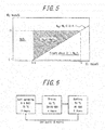
- FIG. 5 illustrates a relationship between Si content and Mg content in the hot-dip coating and the state of phases formed in the main layer of the hot-dip coating. It can be seen from FIG. 5 that within the scope of the disclosed composition (area surrounded by a dashed line in FIG. 5 ), single phase Si can be reliably eliminated from the main layer when formula (I) is satisfied.
- the main layer of the hot-dip coating includes ⁇ -Al phase dendritic regions.
- the mean dendrite diameter of these dendritic regions and the thickness of the hot-dip coating satisfy the following formula (2): t / d ⁇ 1.5 where t represents the thickness of the hot-dip coating ( ⁇ m) and d represents the mean dendrite diameter ( ⁇ m).
- the arms of the dendritic regions composed by the ⁇ -Al phase can be kept relatively small (i.e., the mean dendrite diameter can be kept relatively small), Mg 2 Si can be effectively dispersed in the interdendritic regions, and a state can be obtained in which Mg 2 Si is finely and uniformly dispersed throughout the main layer of the hot-dip coating without uneven distribution.
- FIGS. 1A and 1B schematically illustrate the change in state of a main layer of a hot-dip coating during corrosion of a worked part in the case of the disclosed hot-dip Al-Zn-Mg-Si coated steel sheet and in the case of a hot-dip Al-Zn-Mg-Si coated steel sheet according to a conventional technique.
- the dendrites are small relative to the thickness t of the hot-dip coating, which facilitates fine and uniform dispersion of Mg 2 Si.
- Mg 2 Si that is present at fracture surfaces of the cracks into the worked part of the hot-dip coating dissolves, and Mg concentrates at the surface of the corrosion products.
- the dendrites are large relative to the thickness t of the hot-dip coating, which makes fine and uniform dispersion of Mg 2 Si difficult.
- Mg 2 Si that is present at fracture surfaces of the cracks into the worked part dissolves, and Mg concentrates along some of the surface of the corrosion product.
- FIG. 2 illustrates, by energy dispersive X-ray spectroscopy using a scanning electron microscope (SEM-EDS), the states of various elements when a worked part is corroded in the case of the disclosed hot-dip Al-Zn-Mg-Si coated steel sheet. It can be seen from FIG. 2 that when a worked part is corroded in the disclosed hot-dip Al-Zn-Mg-Si coated steel sheet, Mg concentrates at the surface of the main layer of the hot-dip coating (refer to the photograph for Mg in FIG. 2 ).
- SEM-EDS scanning electron microscope
- FIG. 3 illustrates, by SEM-EDS, the states of various elements in the case of a hot-dip Al-Zn-Mg-Si coated steel sheet in which the hot-dip coating has a composition within the scope of this disclosure (Al: 55 mass%, Si: 1.6 mass%, Mg: 2.5 mass%), but in which the mean dendrite diameter of dendritic regions in the main layer and the thickness of the hot-dip coating do not satisfy the above formula (2).
- Al 55 mass%
- Si 1.6 mass%
- Mg 2.5 mass%
- dendrite diameter refers to the center distance between adjacent dendrite arms (dendrite arm spacing).
- the dendrite diameter is measured in accordance with the secondary dendrite arm spacing method (refer to " Japan Institute of Light Metals, Committee of Casting and Solidification; Journal of Japan Institute of Light Metals; Vol. 38; p 54; 1988 ").
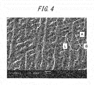
- the dendritic regions of the main layer of the hot-dip coating have a high level of orientation and there are large number of regions in which the arms are aligned.
- the surface of the main layer of the hot-dip coating is polished and/or etched and is observed under magnification (for example, observed under x200 magnification) using a scanning electron microscope (SEM), and in a randomly selected field of view, a region where at least three dendrite arms are aligned is selected (three dendrites between A and B are selected in FIG. 4 ), and the distance along a direction of alignment of the arms (distance L in FIG. 4 ) is measured. Thereafter, the measured distance is divided by the number of dendrite arms (L/3 in FIG. 4 ) to calculate the dendrite diameter. The dendrite diameter is measured at three or more locations in one field of view, and the mean of the dendrite diameters obtained at these locations is calculated to determine the mean dendrite diameter.
- magnification for example, observed under x200 magnification
- SEM scanning electron microscope
- the main layer contains Mg 2 Si as described above, and the Mg 2 Si content in the main layer is 1.0 mass% or more.
- Mg 2 Si content is measured by, for example, dissolving the hot-dip coating of the Al-Zn-Mg-Si coated steel sheet in acid and then measuring the amounts (g/m2) of Si and Mg by ICP analysis (high-frequency inductively coupled plasma emission spectroscopy).
- the content in the interfacial alloy layer (0.45 g/m 2 per 1 ⁇ m of interfacial alloy layer) is subtracted from the amount of Si, and the difference is multiplied by 2.7 to convert to the amount (g/m 2 ) of Mg 2 Si, which is then divided by the hot-dip coating weight (g/m 2 ) to calculate the mass percentage of Mg 2 Si.
- any analytical method by which the Mg 2 Si content can be determined may be used.
- the area ratio of Mg 2 Si in the main layer upon observation of a cross-section of the main layer is 1 % or more. This enables fine and uniform dispersion of Mg 2 Si throughout the main layer of the hot-dip coating in a more reliable manner such that the desired corrosion resistance can be achieved.
- the area ratio of Mg 2 Si is determined by, for example, performing SEM-EDX mapping of a cross-section of the hot-dip coating of the Al-Zn-Mg-Si coated steel sheet and then using image processing to calculate the area ratio (%) of regions where Mg and Si are detected overlapping with one another (i.e., regions where Mg 2 Si is present) in one field of view.
- any method that can determine the area ratio of regions where Mg 2 Si is present may be used.
- a tube voltage of 30 kV a tube current of 10 mA
- Cu K ⁇ tube 0.154 nm
- 2 ⁇ a measurement angle 2 ⁇ of from 10° to 90°
- the ratio of the minor diameter thereof relative to the major diameter thereof is 0.4 or less, and more preferably 0.3 or less.
- the ratio of the minor diameter relative to the major diameter of Mg 2 Si particles is 0.4 or more as described, for example, in PTL 3. Since Mg 2 Si is coarse and has an uneven distribution in this situation, the dissolution rate of Mg 2 Si during initial corrosion is much higher than that of Zn, and Mg 2 Si preferentially dissolves and elutes, as a result of which, Mg is not effectively taken into the corrosion products, a smaller number of localized Mg-rich sections form at the surface of the corrosion products, and an effect of corrosion resistance improvement is not obtained.
- the "major diameter” of Mg 2 Si refers to the longest diameter in a Mg 2 Si particle and the "minor diameter” of Mg 2 Si refers to a shortest diameter in a Mg 2 Si particle.
- the hot-dip coating preferably further contains Ca.
- the total Ca content is preferably from 0.2 mass% to 25 mass%. When the total content is within the range set forth above, an adequate corrosion delaying effect can be obtained without this effect reaching saturation.
- the main layer optionally further contains one or more selected from Mn, V, Cr, Mo, Ti, Sr, Ni, Co, Sb, and B in a total amount of from 0.01 mass% to 10 mass% because, in the same way as Mg and Ca, they improve the stability of corrosion products and have an effect of delaying progression of corrosion.
- the interfacial alloy layer is present at the interface with the base steel sheet and, as previously mentioned, is an Fe-Al compound and/or an Fe-Al-Si compound that is inevitably formed by alloying reaction between Fe in the surface of the base steel sheet and Al and/or Si in the molten bath. Since the interfacial alloy layer is hard and brittle, it may act as a start point for cracks during working if it grows thick. Therefore, the thickness of the interfacial alloy layer is preferably minimized.
- the interfacial alloy layer and the main layer can be examined by using a scanning electron microscope or the like to observe a polished and/or etched cross-section of the hot-dip coating.
- a scanning electron microscope or the like to observe a polished and/or etched cross-section of the hot-dip coating.
- various methods for polishing and etching the cross-section there is no specific limitation on which method is used as long as the method is normally used for observing hot-dip coating cross-sections.
- observation conditions using a scanning electron microscope it is possible to clearly observe the alloy layer and the main layer, for example, in a backscattered electron image at a magnification of ⁇ 1,000 or more, with an acceleration voltage of 15 kV.
- the presence or absence of Mg and one or more selected from Ca, Mn, V, Cr, Mo, Ti, Sr, Ni, Co, Sb, and B in the main layer can be confirmed by, for example, performing penetration analysis of the hot-dip coating using a glow discharge emission analyzer.
- a glow discharge emission analyzer is only intended as an example, and any other methods enabling examination of the presence and distribution of Mg, Ca, Mn, V, Cr, Mo, Ti, Sr, Ni, Co, Sb, and B in the main layer of the hot-dip coating can be adopted.
- the aforementioned one or more selected from Ca, Mn, V, Cr, Mo, Ti, Sr, Ni, Co, Sb, and B form an intermetallic compound with one or more selected from Zn, Al, and Si in the main layer of the hot-dip coating.
- the ⁇ -Al phase solidifies before the Zn-rich phase, and therefore the intermetallic compound is discharged from the ⁇ -Al phase during the solidification process and gathers in the Zn-rich phase in the main layer of the hot-dip coating.
- the one or more selected from Ca, Mn, V, Cr, Mo, Ti, Sr, Ni, Co, Sb, and B are taken into the corrosion products.
- Si it is more preferable for Si to be included in the intermetallic compound because this means that the intermetallic compound absorbs Si within the hot-dip coating to reduce excessive Si in the main layer of the hot-dip coating and, as a result, a decrease in bending workability caused by formation of non-solute Si (Si phase) in the main layer of the hot-dip coating can be prevented.
- the following methods may be used to confirm whether Mg or one or more selected from Ca, Mn, V, Cr, Mo, Ti, Sr, Ni, Co, Sb, and B form an intermetallic compound with one or more selected from Zn, Al, and Si.
- methods that can be used include a method of detecting such intermetallic compounds by wide angle X-ray diffraction from the surface of the hot-dip coated steel sheet and a method of detecting such intermetallic compounds by performing electron beam diffraction with a transmission electron microscope on a cross-section of the hot-dip coating. Moreover, as long as such intermetallic compounds can be detected, any other method can be used.
- the thickness of the hot-dip coating of the disclosed hot-dip Al-Zn-Mg-Si coated steel sheet is preferably 15 ⁇ m or more and 27 ⁇ m or less.
- corrosion resistance tends to become poorer as the thickness of the hot-dip coating is reduced, whereas workability tends to become poorer as the thickness of the hot-dip coating is increased.
- the thickness of the interfacial alloy layer is preferably 1 ⁇ m or less. This is because high workability and better worked part corrosion resistance can be achieved when the thickness of the interfacial alloy layer is I ⁇ m or less. For example, by setting the Si content in the hot-dip coating as greater than 0.6 mass% as previously described, growth of the interfacial alloy layer can be inhibited, and thus the thickness of the interfacial alloy layer can be restricted to 1 ⁇ m or less.
- the thicknesses of the hot-dip coating and the interfacial alloy layer can be obtained by any method that enables accurate determination of these thicknesses. For example, each of these thicknesses may be determined by observing a cross-section of the hot-dip Al-Zn-Mg-Si coated steel sheet under an SEM, measuring the thickness at 3 locations in each of 3 fields of view, and then calculating the average of the thicknesses at these 9 measurement locations.
- the disclosed hot-dip Al-Zn-Mg-Si coated steel sheet may be a surface-treated steel sheet that further includes a chemical conversion treatment coating and/or a coating film at the surface thereof.
- the base steel sheet used in the disclosed hot-dip Al-Zn-Mg-Si coated steel sheet.
- the base steel sheet is not limited to being a steel sheet that is the same as used in a typical hot-dip Al-Zn alloy coated steel sheet, and may alternatively be a high tensile strength steel sheet or the like.
- the following describes the disclosed method of producing a hot-dip Al-Zn-Mg-Si coated steel sheet.
- the disclosed method of producing a hot-dip Al-Zn-Mg-Si coated steel sheet includes hot-dip coating a base steel sheet by immersing the base steel sheet in a molten bath containing from 25 mass% to 80 mass% of Al, from greater than 0.6 mass% to 15 mass% of Si, and from greater than 0.1 mass% to 25 mass% of Mg, the balance being Zn and incidental impurities, subsequently cooling a resultant hot-dip coated steel sheet to a first cooling temperature at an average cooling rate of less than 10 °C/sec, the first cooling temperature being no higher than a bath temperature of the molten bath and no lower than 50 °C below the bath temperature, and then cooling the hot-dip coated steel sheet from the first cooling temperature to 380 °C at an average cooling rate of 10 °C/sec or more.
- the disclosed production method enables production of a hot-dip Al-Zn-Mg-Si coated steel sheet having good corrosion resistance in flat parts and edge parts, and also having excellent worked part corrosion resistance.
- a hot rolled steel sheet or steel strip subjected to acid pickling descaling or a cold rolled steel sheet or steel strip obtained by cold rolling the hot rolled steel sheet or steel strip may be used.
- the hot dip coating conditions may be in accordance with a conventional method without any specific limitations as long as an hot-dip Al-Zn alloy coating can be formed on the base steel sheet.
- the base steel sheet may be subjected to reduction annealing, then cooled to a temperature close to the temperature of the molten bath, immersed in the molten bath, and then subjected to wiping to form a hot-dip coating of a desired thickness.
- the molten bath for hot-dip coating has a composition containing from 25 mass% to 80 mass% of Al, from greater than 0.6 mass% to 15 mass% of Si, and from greater than 0.1 mass% to 25 mass% of Mg, the balance being Zn and incidental impurities.
- the molten bath may further contain Ca for the purpose of further improving corrosion resistance.
- the molten bath may contain one or more selected from Mn, V, Cr, Mo, Ti, Sr, Ni, Co, Sb, and B in a total amount of from 0.01 mass% to 10 mass%. Setting the composition of the molten bath as described above enables formation of the hot-dip coating.
- the temperature of the molten bath other than being a temperature that enables hot-dip Al-Zn-Mg-Si coating without solidification of the molten bath, and a commonly known molten bath temperature may be adopted.
- the temperature of a molten bath in which the Al concentration is 55 mass% is preferably from 575 °C to 620 °C, and more preferably from 580 °C to 605 °C.
- the hot-dip Al-Zn alloy coating includes an interfacial alloy layer present at an interface with the base steel sheet, and a main layer present on the interfacial alloy layer.
- the composition of the main layer has slightly lower Al and Si contents at the interfacial alloy layer side thereof, as a whole, the composition is substantially the same as the composition of the molten bath. Therefore, the composition of the main layer of the hot-dip coating can be precisely controlled by controlling the composition of the molten bath.
- the steel sheet resulting from the hot dip coating is cooled to the first cooling temperature at an average cooling rate of less than 10 °C/sec, and is then cooled from the first cooling temperature to 380 °C at an average cooling rate of 10 °C/sec or more.
- the average cooling rate from the first cooling temperature to 380 °C is preferably 20 °C/sec or more, and more preferably 40 °C/sec or more.
- a hot-dip Al-Zn-Mg-Si coated steel sheet may be produced in accordance with a conventional method without any specific limitations.
- a chemical conversion treatment coating may be formed on the surface of the hot-dip Al-Zn-Mg-Si coated steel sheet (chemical conversion treatment process) or a coating film may be formed on the surface of the hot-dip Al-Zn-Mg-Si coated steel sheet in a separate coating line (coating film formation process).
- the chemical conversion treatment coating can be formed by a chromating treatment or a chromium-free chemical conversion treatment where, for example, a chromating treatment liquid or a chromium-free chemical conversion treatment liquid is applied, and without water washing, drying treatment is performed with a steel sheet temperature of 80 °C to 300 °C.
- These chemical conversion treatment coatings may have a single-layer structure or a multilayer structure, and in the case of a multilayer structure, chemical conversion treatment can be performed multiple times sequentially.
- Methods of forming the coating film include roll coater coating, curtain flow coating, and spray coating.
- the coating film can be formed by applying a coating material containing organic resin, and then heating and drying the coating material by hot air drying, infrared heating, induction heating, or other means.
- Hot-dip Al-Zn-Mg-Si coated steel sheet samples 1 to 57 were each produced in a continuous galvanizing line (CGL) using, as a base steel sheet, a cold rolled steel sheet of 0.5 mm in thickness that was produced by a conventional method.
- CGL continuous galvanizing line
- Production conditions molten bath temperature, first cooling temperature, and cooling rate
- hot-dip coating conditions composition, major diameter of Mg 2 Si, minor diameter/major diameter of Mg 2 Si, thickness of hot-dip coating, left side of formula (1), left side of formula (2), Mg 2 Si content in main layer, Mg 2 Si area ratio in main layer cross-section, intensity ratio of Mg 2 Si relative to Al, and thickness of interfacial alloy layer
- Table 1 molten bath temperature, first cooling temperature, and cooling rate
- hot-dip coating conditions composition, major diameter of Mg 2 Si, minor diameter/major diameter of Mg 2 Si, thickness of hot-dip coating, left side of formula (1), left side of formula (2), Mg 2 Si content in main layer, Mg 2 Si area ratio in main layer cross-section, intensity ratio of Mg 2 Si relative to Al, and thickness of interfacial alloy layer
- the bath temperature of the molten bath was 590 °C in production of all the above hot-dip Al-Zn-Mg-Si coated steel sheet samples.
- Sample 10 was subjected to treatment of being held at 200 °C for 30 minutes after hot-dip coating.
- the compositions of hot-dip coatings in samples 11 to 13, 20, and 21 were within the same ranges as disclosed in PTL 2, whereas the compositions of hot-dip coatings in samples 28, 29, and 32 were within the same ranges as disclosed in PTL 3.
- the major and minor diameters of Mg 2 Si were determined for each hot-dip Al-Zn-Mg-Si coated steel sheet sample by imaging the surface of the hot-dip coating using an optical microscope ( ⁇ 100 magnification), randomly selecting five Mg 2 Si particles, measuring the major diameter and minor diameter of each of the selected Mg 2 Si particles, and calculating the averages of these measured major diameters and minor diameters.
- the major diameter ( ⁇ m) and ratio of minor diameter relative to major diameter that were determined for Mg 2 Si are shown in Table 1.
- the dendrite diameter was determined for each hot-dip Al-Zn-Mg-Si coated steel sheet sample by observing a polished surface of a main layer of the hot-dip coating at ⁇ 200 magnification using an SEM, selecting a region in which at least three dendrite arms were aligned in a randomly selected field of view, measuring the distance along the direction of alignment of the arms, and then dividing the measured distance by the number of dendrite arms.
- the dendrite diameter was measured at three locations in one field of view and the mean of the measured dendrite diameters was calculated to determine the mean dendrite diameter.
- the determined dendrite diameter is shown in Table 1.
- Each hot-dip Al-Zn-Mg-Si coated steel sheet sample was subjected to a Japan Automotive Standards Organization Cyclic Corrosion Test (JASO-CCT).
- Each cycle of the JASO-CCT included salt spraying, drying, and wetting under specific conditions as illustrated in FIG. 6 .
- Each hot-dip Al-Zn-Mg-Si coated steel sheet sample was worked by 180° bending to sandwich three sheets of the same sheet thickness at the inside (3T bending), and was then subjected to a Japan Automotive Standards Organization Cyclic Corrosion Test (JASO-CCT) at the outside of the bend.
- Each cycle of the JASO-CCT included salt spraying, drying, and wetting under specific conditions as illustrated in FIG. 6 .
- Example 1 Some of the hot-dip Al-Zn-Mg-Si coated steel sheet samples produced in Example 1 (refer to Table 2 for the sample numbers) were subjected to formation of a urethane resin-based chemical conversion coating (CT-E-364 produced by Nihon Parkerizing Co., Ltd.). The coating weight of the chemical conversion coating was 1 g/m 2 .
- Production conditions molten bath temperature, first cooling temperature, and cooling rate
- hot-dip coating conditions composition, major diameter of Mg 2 Si, minor diameter/major diameter of Mg 2 Si, thickness of hot-dip coating, left side of formula (I), left side of formula (2), Mg 2 Si content in main layer, Mg 2 Si area ratio in main layer cross-section, intensity ratio of Mg 2 Si relative to Al, and thickness of interfacial alloy layer
- Table 2 molten bath temperature, first cooling temperature, and cooling rate
- hot-dip coating conditions composition, major diameter of Mg 2 Si, minor diameter/major diameter of Mg 2 Si, thickness of hot-dip coating, left side of formula (I), left side of formula (2), Mg 2 Si content in main layer, Mg 2 Si area ratio in main layer cross-section, intensity ratio of Mg 2 Si relative to Al, and thickness of interfacial alloy layer
- Each hot-dip Al-Zn-Mg-Si coated steel sheet sample on which a chemical conversion coating had been formed was subjected to a Japan Automotive Standards Organization Cyclic Corrosion Test (JASO-CCT).
- Each cycle of the JASO-CCT included salt spraying, drying, and wetting under specific conditions as illustrated in FIG. 6 .
- Each hot-dip Al-Zn-Mg-Si coated steel sheet sample on which a chemical conversion coating had been formed was worked by 180° bending to sandwich three sheets of the same sheet thickness at the inside (3T bending), and was then subjected to a Japan Automotive Standards Organization Cyclic Corrosion Test (JASO-CCT) at the outside of the bend.
- Each cycle of the JASO-CCT included salt spraying, drying, and wetting under specific conditions as illustrated in FIG. 6 .
- Example 2 With respect to each of the hot-dip Al-Zn-Mg-Si coated steel sheet samples subjected to formation of a chemical conversion coating in Example 2, 5 ⁇ m of an epoxy resin-based primer (JT-25 produced by Nippon Fine Coatings) and 15 ⁇ m of a melamine cured polyester-based top coating (NT-GLT produced by Nippon Fine Coatings) were applied in this order and dried to produce a coated steel sheet sample.
- JT-25 produced by Nippon Fine Coatings
- NT-GLT melamine cured polyester-based top coating
- Production conditions molten bath temperature, first cooling temperature, and cooling rate
- hot-dip coating conditions composition, major diameter of Mg 2 Si, minor diameter/major diameter of Mg 2 Si, thickness of hot-dip coating, left side of formula (I), left side of formula (2), Mg 2 Si content in main layer, Mg 2 Si area ratio in main layer cross-section, intensity ratio of Mg 2 Si relative to Al, and thickness of interfacial alloy layer
- Table 3 molten bath temperature, first cooling temperature, and cooling rate
- hot-dip coating conditions composition, major diameter of Mg 2 Si, minor diameter/major diameter of Mg 2 Si, thickness of hot-dip coating, left side of formula (I), left side of formula (2), Mg 2 Si content in main layer, Mg 2 Si area ratio in main layer cross-section, intensity ratio of Mg 2 Si relative to Al, and thickness of interfacial alloy layer
- Each coated steel sheet sample was worked by 180° bending to sandwich three sheets of the same sheet thickness at the inside (3T bending), and was then subjected to a Japan Automotive Standards Organization Cyclic Corrosion Test (JASO-CCT) at the outside of the bend.
- Each cycle of the JASO-CCT included salt spraying, drying, and wetting under specific conditions as illustrated in FIG. 6 .
- Example 1 Some of the hot-dip Al-Zn-Mg-Si coated steel sheet samples produced in Example 1 (refer to Table 4 for the sample numbers) were each sheared to a size of 90 mm ⁇ 70 mm and then subjected to zinc phosphate treatment as chemical conversion treatment, followed by electrodeposition coating, intermediate coating, and top coating in the same way as in coating treatment for an automobile outer panel.
- Zinc phosphate treatment A degreasing agent "FC-E2001” produced by Nihon Parkerizing Co., Ltd., a surface-modifying agent “PL-X” produced by Nihon Parkerizing Co., Ltd., and a zinc phosphate treatment agent "PB-AX35M” (temperature: 35°C) produced by Nihon Parkerizing Co., Ltd. were used under conditions of a free-fluorine concentration in the zinc phosphate treatment liquid of 200 ppm and an immersion time in the zinc phosphate treatment liquid of 120 seconds.
- Electrodeposition coating An electrodeposition coating material "GT-100" produced by Kansai Paint Co., Ltd. was used to perform electrodeposition coating with a thickness of 15 ⁇ m.
- Intermediate coating An intermediate coating material "TP-65-P" produced by Kansai Paint Co., Ltd. was used to perform spray coating with a thickness of 30 ⁇ m.
- Top coating A top coating material "Neo6000" produced by Kansai Paint Co., Ltd. was used to perform spray coating with a thickness of 30 ⁇ m.
- Production conditions molten bath temperature, first cooling temperature, and cooling rate
- hot-dip coating conditions composition, major diameter of Mg 2 Si, minor diameter/major diameter of Mg 2 Si, thickness of hot-dip coating, left side of formula (I), left side of formula (2), Mg 2 Si content in main layer, Mg 2 Si area ratio in main layer cross-section, intensity ratio of Mg 2 Si relative to Al, and thickness of interfacial alloy layer
- Table 4 molten bath temperature, first cooling temperature, and cooling rate
- hot-dip coating conditions composition, major diameter of Mg 2 Si, minor diameter/major diameter of Mg 2 Si, thickness of hot-dip coating, left side of formula (I), left side of formula (2), Mg 2 Si content in main layer, Mg 2 Si area ratio in main layer cross-section, intensity ratio of Mg 2 Si relative to Al, and thickness of interfacial alloy layer
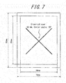
- a sample for evaluating post-coating corrosion resistance was obtained as illustrated in FIG. 7 by using tape to seal a non-evaluation surface (rear surface) and a 5 mm edge part of an evaluation surface, and then using a cutter knife to form a cross-cut scar in the center of the evaluation surface with a length of 60 mm and a center angle of 90°, and to a depth reaching the steel substrate of the hot-dip coated steel sheet.
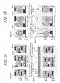
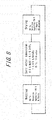
- the evaluation sample was subjected to an accelerated corrosion test (SAE J 2334) through cycles illustrated in FIG. 8 .
- the accelerated corrosion test was started from wetting and was continued until 30 cycles had been completed.
- the coating film blister width of a part at which greatest coating film blistering from the scar part occurred was measured, and then post-coating corrosion resistance was evaluated in accordance with the following standard. The evaluation results are shown in Table 4.
- a hot-dip Al-Zn-Mg-Si coated steel sheet having excellent post-coating corrosion resistance can be obtained by controlling the Mg content in the hot-dip coating layer to within an appropriate range.
Description
- This disclosure relates to a hot-dip Al-Zn-Mg-Si coated steel sheet having good corrosion resistance in flat parts and edge parts, and also having excellent corrosion resistance in worked parts.
- Hot-dip Al-Zn alloy-coated steel sheets have both the sacrificial protection of Zn and the high corrosion resistance of Al, and thus rank highly in terms of corrosion resistance among hot-dip galvanized steel sheets. For example, PTL I (
JP S46-7161 B - The hot-dip coating of a hot-dip Al-Zn alloy-coated steel sheet includes a main layer and an alloy layer present at an interface of the main layer with a base steel sheet. The main layer is mainly composed of regions where Zn is contained in a supersaturated state and Al is solidified by dendrite solidification (α-Al phase dendritic regions), and remaining interdendritic regions between the dendrites, and has a structure with the α-Al phase stacked in multiple layers in the thickness direction of the hot-dip coating. Due to such characteristic hot-dip coating structure, the corrosion path from the surface becomes complex, making it difficult for corrosion to reach the base steel sheet. Therefore, better corrosion resistance can be achieved with a hot-dip Al-Zn alloy-coated steel sheet than with a hot-dip galvanized steel sheet having the same hot-dip coating thickness.
- The inclusion of Mg in a hot-dip Al-Zn alloy coating is a known technique for further improving corrosion resistance.
- In one example of a technique relating to a hot-dip Al-Zn alloy-coated steel sheet containing Mg (hot-dip Al-Zn-Mg-Si coated steel sheet), PTL 2 (
JP 5020228 B - Moreover, PTL 3 (
JP 5000039 B - Hot-dip Al-Zn alloy-coated steel sheets that are to be used in the automotive field, and particularly those that are to be used for outer panels, are typically supplied to automobile manufacturers and the like in a state in which production up to hot-dip coating in a continuous galvanizing line (CGL) has been completed. After being worked into the shape of a panel component, the hot-dip Al-Zn alloy-coated steel sheet is typically subjected to chemical conversion treatment, and also general coating for automobile use by electrodeposition coating, intermediate coating and top coating. However, when a coating film of an outer panel obtained using a hot-dip Al-Zn alloy-coated steel sheet is scarred, the resulting scar acts as a start point for selective corrosion of interdendritic regions present at the interface of the coating film and the hot-dip coating that contain a large amount of Zn. As a result, there have been cases in which significantly greater coating film blistering has occurred than with a hot-dip Zn coating and in which it has not been possible to ensure adequate corrosion resistance (post-coating corrosion resistance). In response, PTL 4 (
JP 2002-12959 A -
- PTL 1:
JP S46-7161 B - PTL 2:
JP 5020228 B - PTL 3:
JP 5000039 B - PTL 4:
JP 2002-12959 A - Further examples of hot-dip coated steel sheets are disclosed in
US 2012/0282488 A1 andEP 1 225 246 A1 . - As mentioned above, due to their excellent corrosion resistance, hot-dip Al-Zn alloy-coated steel sheets are often used in the field of building materials for roofs, walls, and the like that undergo long-term exposure to outdoor environments. Therefore, there is demand for the development of hot-dip Al-Zn-Mg-Si coated steel sheets with even better corrosion resistance in order to extend product life in response to recent requirements for resource conservation and energy efficiency.
Moreover, in the hot-dip Al-Zn-Mg-Si coated steel sheets disclosed inPTL 2 and 3, the hot-dip coating has a hard main layer and thus tends to crack when worked by bending. This is problematic as the cracking results in poorer corrosion resistance in worked parts (worked part corrosion resistance). - Therefore, there is also demand for the improvement of worked part corrosion resistance. Also note that although reduced ductility due to Mg addition is remedied in
PTL 2 through a "small" spangle size, in reality, it is essential that TiB is present in the hot-dip coating inPTL 2 in order to achieve this objective, and thusPTL 2 is not considered to disclose a fundamental solution. - Furthermore, even when the hot-dip Al-Zn alloy-coated steel sheet disclosed in PTL 4 is subjected to subsequent coating, the problem in relation to post-coating corrosion resistance is not resolved, and there are some applications for hot-dip Al-Zn alloy-coated steel sheets in which there is still demand for further improvement of post-coating corrosion resistance.
- In view of the circumstances set forth above, it would be helpful to provide a hot-dip Al-Zn-Mg-Si coated steel sheet having good corrosion resistance in flat parts and edge parts, and also having excellent worked part corrosion resistance, and to provide a method of producing this hot-dip Al-Zn-Mg-Si coated steel sheet.
- As a result of extensive studies conducted with the aim of solving the problems set forth above, we decided to focus on a finding that in corrosion of a hot-dip Al-Zn-Mg-Si coated steel sheet, Mg2Si present in interdendritic regions of a main layer of the hot-dip coating dissolves during initial corrosion, and Mg concentrates at the surface of corrosion products, which contributes to improvement of corrosion resistance, and also a finding that it is necessary to eliminate single phase Si since single phase Si present in the main layer acts as a cathode site, leading to dissolution of the surrounding hot-dip coating. We conducted further intensive research and discovered that worked part corrosion resistance can be significantly improved by prescribing the contents of Al, Mg, and Si components present in the main layer of the hot-dip coating and controlling the contents of Mg and Si in the hot-dip coating to within specific ranges such as to enable fine and uniform dispersion of Mg2Si in the interdendritic regions of the main layer. We also discovered that fine and uniform formation of Mg2Si can eliminate single phase Si from the main layer of the hot-dip coating, and thereby also improve corrosion resistance of flat parts and edge parts.
- In addition to the above, we discovered that by controlling the Mg content in the hot-dip coating to within a specific range, excellent post-coating corrosion resistance can be obtained.
- This disclosure is made based on these discoveries and primary features thereof are as specified in the claims.
- According to this disclosure, it is possible to provide a hot-dip Al-Zn-Mg-Si coated steel sheet having good corrosion resistance in flat parts and edge parts, and also having excellent worked part corrosion resistance. The method of producing this hot-dip Al-Zn-Mg-Si coated steel sheet is also disclosed.
- In the accompanying drawings:
-
FIG. 1A illustrates pre- and post-corrosion states of a worked part of a disclosed hot-dip Al-Zn-Mg-Si coated steel sheet andFIG. 1B illustrates pre and post-corrosion states of a worked part of a conventional hot-dip Al-Zn-Mg-Si coated steel sheet; -
FIG. 2 illustrates, by scanning electron microscope energy dispersive X-ray spectroscopy (SEM-EDX), the states of various elements in a situation in which a worked part of a disclosed hot-dip Al-Zn-Mg-Si coated steel sheet is corroded; -
FIG. 3 illustrates, by SEM-EDX, the states of various elements in the case of a conventional hot-dip Al-Zn-Mg-Si coated steel sheet; -
FIG. 4 illustrates a method of measuring dendrite diameter; -
FIG. 5 illustrates a relationship between Si content and Mg content in a hot-dip coating and the state of phases formed in a main layer of the hot-dip coating; -
FIG. 6 illustrates the procedure of a Japan Automotive Standards Organization Cyclic Corrosion Test (JASO-CCT); -
FIG. 7 illustrates a sample for evaluation of post-coating corrosion resistance; and -
FIG. 8 illustrates a cycle of an accelerated corrosion test (SAE J 2334). - The hot-dip Al-Zn-Mg-Si coated steel sheet to which this disclosure relates includes a base steel sheet and a hot-dip coating on a surface of the base steel sheet. The hot-dip coating includes an interfacial alloy layer present at an interface with the base steel sheet, and a main layer present on the interfacial alloy layer. The hot-dip coating has a composition containing from 25 mass% to 80 mass% of Al, from greater than 0.6 mass% to 15 mass% of Si, and from greater than 0.1 mass% to 25 mass% of Mg, the balance being Zn and incidental impurities.
- The Al content in the hot-dip coating is set as from 25 mass% to 80 mass%, and preferably from 35 mass% to 65 mass% from a viewpoint of balancing corrosion resistance with actual operation requirements. When the Al content of the main layer of the hot-dip coating is 25 mass% or more, dendrite solidification of Al occurs. This ensures a structure having excellent corrosion resistance in which the main layer is composed mainly of regions in which Zn is in a supersaturated state and Al is solidified by dendrite solidification (α-Al phase dendritic regions) and remaining interdendritic regions between the dendrites, and in which the dendritic regions are stacked in the thickness direction of the hot-dip coating. Corrosion resistance is improved as the number of stacked α-Al phase dendritic regions increases because the corrosion path becomes more complex, which makes it more difficult for corrosion to reach the base steel sheet. To obtain significantly high corrosion resistance, the Al content of the main layer is more preferably 35 mass% or more. On the other hand, if the Al content of the main layer is greater than 80 mass%, the content of Zn having sacrificial corrosion protection ability with respect to Fe decreases, and corrosion resistance deteriorates. Accordingly, the Al content of the main layer is set as 80 mass% or less. Furthermore, when the Al content of the main layer is 65 mass% or less, sacrificial corrosion protection ability with respect to Fe is ensured and adequate corrosion resistance is obtained even if the coating weight of the hot-dip coating is reduced and the steel base becomes more easily exposed. Accordingly, the Al content of the main layer of the hot-dip coating is preferably 65 mass% or less.
- Si inhibits the growth of the interfacial alloy layer formed at the interface with the base steel sheet and is added to a molten bath for improving corrosion resistance and workability. Therefore, Si is inevitably contained in the main layer of the hot-dip coating. Specifically, when hot-dip coating treatment is performed in a molten bath containing Si in the case of an Al-Zn-Mg-Si coated steel sheet, an alloying reaction takes place between Fe in the surface of the base steel sheet and Al or Si in the bath upon immersion of the steel sheet in the molten bath, whereby an Fe-Al compound and/or an Fe-Al-Si compound is formed. The formation of this Fe-Al-Si interfacial alloy layer inhibits growth of the interfacial alloy layer. A Si content of greater than 0.6 mass% in the hot-dip coating enables adequate inhibition of interfacial alloy layer growth. On the other hand, if the Si content in the hot-dip coating is greater than 15 mass%, this may provide a propagation path for cracks in the hot-dip coating, which reduces workability and facilitates precipitation of a Si phase that then acts as a cathode site. Although precipitation of the Si phase can be inhibited by increasing the Mg content, this method leads to increased production cost and complicates management of the molten bath composition. Accordingly, the Si content in the hot-dip coating is set as 15 mass% or less. From a viewpoint of achieving a higher level of inhibition of both interfacial alloy layer growth and Si phase precipitation, the Si content in the hot-dip coating is preferably from greater than 2.3 mass% to 5 mass%, and particularly preferably from greater than 2.3 mass% to 3.5 mass%.
- The hot-dip coating contains from greater than 0.1 mass% to 25 mass% of Mg. When the main layer of the hot-dip coating is corroded, Mg becomes included in the corrosion products, which improves the stability of the corrosion products and delays corrosion progression, resulting in an effect of improved corrosion resistance. More specifically, Mg in the main layer of the hot-dip coating bonds to the Si described above to form Mg2Si. When the hot-dip coated steel sheet is corroded, this Mg2Si dissolves during initial corrosion, and thus Mg is included in the corrosion products. Mg concentrates at the surface of the corrosion products and has an effect of densifying the corrosion products such as to improve stability of the corrosion products and barrier properties against external causes of corrosion.
- The reason for setting the Mg content of the hot-dip coating as greater than 0.1 mass% is that Mg2Si can be formed and a corrosion delaying effect can be obtained when the Mg content is greater than 0.1 mass%. On the other hand, the reason for setting the Mg content as 25 mass% or less is that, when the Mg content is greater than 25 mass%, in addition to the effect of corrosion resistance improvement reaching saturation, production cost increases and management of the molten bath composition becomes complicated. From a viewpoint of achieving a greater corrosion delaying effect while also reducing production cost, the Mg content in the hot-dip coating is preferably from 3 mass% to 10 mass%, and more preferably from 4 mass% to 6 mass%.
- Moreover, a Mg content in the hot-dip coating of 5 mass% or more can improve post-coating corrosion resistance, which is one objective in the present disclosure. In the case of a conventional hot-dip Al-Zn alloy-coated steel sheet that does not contain Mg, a dense and stable oxide film of Al2O3 forms at the periphery of the α-Al phase straight after the hot-dip coating is exposed to the atmosphere. Through the protective action of this oxide film, solubility of the α-Al phase becomes significantly lower than that of a Zn-rich phase in the interdendritic regions. Consequently, upon scarring of the coating film of a coated steel sheet obtained using the conventional hot-dip Al-Zn alloy-coated steel sheet as a base, the scar acts as a start point for selective corrosion of the Zn-rich phase at an interface of the coating film and the hot-dip coating, and this corrosion progresses deep into a part where the coating film is not scarred, causing large coating film blisters. Therefore, post-coating corrosion resistance is poor. On the other hand, in the case of a coated steel sheet obtained using a hot-dip Al-Zn alloy-coated steel sheet that contains Mg as a base, a Mg2Si phase that precipitates in interdendritic regions or Mg-Zn compound (MgZn2, Mg32(Al,Zn)49, etc.) dissolves from an initial stage of corrosion and Mg is taken into the corrosion products. Corrosion products including Mg are highly stable, which inhibits corrosion from the initial stage thereof. Moreover, this can inhibit large coating film blisters caused by selective corrosion of the Zn-rich phase, which is a problem in the case of a coated steel sheet obtained using the conventional hot-dip Al-Zn alloy-coated steel sheet as a base. Consequently, a hot-dip Al-Zn alloy-coated steel sheet having a Mg-containing hot-dip coating displays excellent post-coating corrosion resistance. When the Mg content is 5 mass% or less, post-coating corrosion resistance may not be improved because the amount of Mg that dissolves during corrosion is small and thus stable corrosion products such as described above are not sufficiently formed. Conversely, when the Mg content is greater than 10 mass%, not only does the effect thereof reach saturation, but strong Mg compound corrosion occurs and solubility of the hot-dip coating layer as a whole is excessively increased. As a result, a large blister width may arise and deterioration of post-coating corrosion resistance may occur even if the corrosion products are stabilized because the dissolution rate of the hot-dip coating layer is increased. Accordingly, the Mg content is preferably in a range of from greater than 5 mass% to 10 mass% so as to ensure excellent post-coating corrosion resistance.
- In the disclosed hot-dip Al-Zn-Mg-Si coated steel sheet, from a viewpoint of effectively dispersing Mg2Si in the interdendritic regions, reducing the likelihood of formation of single phase Si, and achieving even better worked part corrosion resistance, it is required that the Mg content and the Si content in the hot-dip coating satisfy the following formula (1):

- Fine and uniform dispersion of Mg2Si can dramatically improve worked part corrosion resistance because Mg2Si gradually dissolves with Zn over the surface of the hot-dip coating and the entirety of the fracture surface of cracks in a worked part, a large amount of Mg is taken into the corrosion products, and a thick Mg-rich section is formed over the whole surface of the corrosion products, thereby inhibiting progression of corrosion. Moreover, fine and uniform dispersion of Mg2Si throughout the main layer of the hot-dip coating without uneven distribution can also improve corrosion resistance of flat parts and edge parts by eliminating single phase Si that acts as a cathode site from the main layer.
- In contrast, according to conventional techniques, as described for example in PTL 3, Mg2Si is present as lumps of at least a certain size (specifically, lumps having a major diameter of 10 µm or more and a ratio of minor diameter to major diameter of 0.4 or more). Therefore, the Mg2Si is coarse and unevenly distributed, and thus has a much higher dissolution rate than Zn during initial corrosion, leading to preferential dissolution and elution of Mg2Si. Consequently, Mg is not effectively taken into the corrosion products, small and localized Mg-rich sections form at the surface of the corrosion products, and the desired effect of corrosion resistance improvement is not obtained.
-
FIG. 5 illustrates a relationship between Si content and Mg content in the hot-dip coating and the state of phases formed in the main layer of the hot-dip coating. It can be seen fromFIG. 5 that within the scope of the disclosed composition (area surrounded by a dashed line inFIG. 5 ), single phase Si can be reliably eliminated from the main layer when formula (I) is satisfied. - The main layer of the hot-dip coating includes α-Al phase dendritic regions. The mean dendrite diameter of these dendritic regions and the thickness of the hot-dip coating satisfy the following formula (2):

- When formula (2) is satisfied, the arms of the dendritic regions composed by the α-Al phase can be kept relatively small (i.e., the mean dendrite diameter can be kept relatively small), Mg2Si can be effectively dispersed in the interdendritic regions, and a state can be obtained in which Mg2Si is finely and uniformly dispersed throughout the main layer of the hot-dip coating without uneven distribution.
-
FIGS. 1A and 1B schematically illustrate the change in state of a main layer of a hot-dip coating during corrosion of a worked part in the case of the disclosed hot-dip Al-Zn-Mg-Si coated steel sheet and in the case of a hot-dip Al-Zn-Mg-Si coated steel sheet according to a conventional technique. - As illustrated in
FIG. 1A , in the case of the disclosed hot-dip Al-Zn-Mg-Si coated steel sheet, the dendrites are small relative to the thickness t of the hot-dip coating, which facilitates fine and uniform dispersion of Mg2Si. When a worked part of the disclosed hot-dip Al-Zn-Mg-Si coated steel sheet is corroded (note that cracks are present in the worked part), Mg2Si that is present at fracture surfaces of the cracks into the worked part of the hot-dip coating dissolves, and Mg concentrates at the surface of the corrosion products. - On the other hand, in the case of the conventional hot-dip Al-Zn-Mg-Si coated steel sheet, as illustrated in
FIG. 1B , the dendrites are large relative to the thickness t of the hot-dip coating, which makes fine and uniform dispersion of Mg2Si difficult. When a worked part of the conventional hot-dip Al-Zn-Mg-Si coated steel sheet is corroded, Mg2Si that is present at fracture surfaces of the cracks into the worked part dissolves, and Mg concentrates along some of the surface of the corrosion product. However, since the degree of dispersion of Mg2Si throughout the main layer of the hot-dip coating is poor compared to the disclosed hot-dip Al-Zn-Mg-Si coated steel sheet, the Mg-rich section covering the surface of the corrosion products is reduced. This is thought to facilitate the progression of corrosion in the worked part, resulting in inadequate corrosion resistance. -
FIG. 2 illustrates, by energy dispersive X-ray spectroscopy using a scanning electron microscope (SEM-EDS), the states of various elements when a worked part is corroded in the case of the disclosed hot-dip Al-Zn-Mg-Si coated steel sheet. It can be seen fromFIG. 2 that when a worked part is corroded in the disclosed hot-dip Al-Zn-Mg-Si coated steel sheet, Mg concentrates at the surface of the main layer of the hot-dip coating (refer to the photograph for Mg inFIG. 2 ). -
FIG. 3 illustrates, by SEM-EDS, the states of various elements in the case of a hot-dip Al-Zn-Mg-Si coated steel sheet in which the hot-dip coating has a composition within the scope of this disclosure (Al: 55 mass%, Si: 1.6 mass%, Mg: 2.5 mass%), but in which the mean dendrite diameter of dendritic regions in the main layer and the thickness of the hot-dip coating do not satisfy the above formula (2). Upon observation, a small amount of precipitation of a Si single phase can be confirmed, and thus reduced corrosion resistance is inferred (refer to the photograph for Si inFIG. 3 ). - The term "dendrite diameter" refers to the center distance between adjacent dendrite arms (dendrite arm spacing). Herein, the dendrite diameter is measured in accordance with the secondary dendrite arm spacing method (refer to "Japan Institute of Light Metals, Committee of Casting and Solidification; Journal of Japan Institute of Light Metals; Vol. 38; p 54; 1988"). In the hot-dip coating of the disclosed hot-dip Al-Zn-Mg-Si coated steel sheet, the dendritic regions of the main layer of the hot-dip coating have a high level of orientation and there are large number of regions in which the arms are aligned.
- Specifically, as illustrated in
FIG. 4 , the surface of the main layer of the hot-dip coating is polished and/or etched and is observed under magnification (for example, observed under x200 magnification) using a scanning electron microscope (SEM), and in a randomly selected field of view, a region where at least three dendrite arms are aligned is selected (three dendrites between A and B are selected inFIG. 4 ), and the distance along a direction of alignment of the arms (distance L inFIG. 4 ) is measured. Thereafter, the measured distance is divided by the number of dendrite arms (L/3 inFIG. 4 ) to calculate the dendrite diameter. The dendrite diameter is measured at three or more locations in one field of view, and the mean of the dendrite diameters obtained at these locations is calculated to determine the mean dendrite diameter. - In the disclosed hot-dip Al-Zn-Mg-Si coated steel sheet, the main layer contains Mg2Si as described above, and the Mg2Si content in the main layer is 1.0 mass% or more. This enables fine and uniform dispersion of Mg2Si throughout the main layer of the hot-dip coating in a more reliable manner such that the desired corrosion resistance can be achieved. Herein, the Mg2Si content is measured by, for example, dissolving the hot-dip coating of the Al-Zn-Mg-Si coated steel sheet in acid and then measuring the amounts (g/m2) of Si and Mg by ICP analysis (high-frequency inductively coupled plasma emission spectroscopy). The content in the interfacial alloy layer (0.45 g/m2 per 1 µm of interfacial alloy layer) is subtracted from the amount of Si, and the difference is multiplied by 2.7 to convert to the amount (g/m2) of Mg2Si, which is then divided by the hot-dip coating weight (g/m2) to calculate the mass percentage of Mg2Si. However, any analytical method by which the Mg2Si content can be determined may be used.
- The area ratio of Mg2Si in the main layer upon observation of a cross-section of the main layer is 1 % or more. This enables fine and uniform dispersion of Mg2Si throughout the main layer of the hot-dip coating in a more reliable manner such that the desired corrosion resistance can be achieved.
- Herein, the area ratio of Mg2Si is determined by, for example, performing SEM-EDX mapping of a cross-section of the hot-dip coating of the Al-Zn-Mg-Si coated steel sheet and then using image processing to calculate the area ratio (%) of regions where Mg and Si are detected overlapping with one another (i.e., regions where Mg2Si is present) in one field of view. However, any method that can determine the area ratio of regions where Mg2Si is present may be used.
- Moreover, with regards to Mg2Si contained in the main layer, it is preferable that according to X-ray diffraction analysis, an intensity ratio of Mg2Si (111) planes (interplanar spacing d = 0.367 nm) relative to Al (200) planes (interplanar spacing d = 0.202 nm) is 0.01 or more. This enables fine and uniform dispersion of Mg2Si throughout the main layer of the hot-dip coating in a more reliable manner such that the desired corrosion resistance can be achieved.
- Herein, this intensity ratio is calculated by obtaining an X-ray diffraction pattern under conditions of, for example, a tube voltage of 30 kV, a tube current of 10 mA, a Cu Kα tube (wavelength λ = 0.154 nm), and a measurement angle 2θ of from 10° to 90°, measuring the intensity of (200) planes (interplanar spacing d = 0.2024 nm) indicating Al and the intensity of (111) planes (interplanar spacing d = 0.367 nm) indicating Mg2Si, and then dividing the latter by the former. However, no specific limitations are placed on the X-ray diffraction analysis conditions.
- With regards to Mg2Si particles that are finely and uniformly dispersed in the interdendritic regions, the ratio of the minor diameter thereof relative to the major diameter thereof is 0.4 or less, and more preferably 0.3 or less.
- In conventional techniques, the ratio of the minor diameter relative to the major diameter of Mg2Si particles is 0.4 or more as described, for example, in PTL 3. Since Mg2Si is coarse and has an uneven distribution in this situation, the dissolution rate of Mg2Si during initial corrosion is much higher than that of Zn, and Mg2Si preferentially dissolves and elutes, as a result of which, Mg is not effectively taken into the corrosion products, a smaller number of localized Mg-rich sections form at the surface of the corrosion products, and an effect of corrosion resistance improvement is not obtained. On the other hand, setting a large difference between the major and minor diameters (aspect ratio) in the disclosed techniques contributes to fine and uniform dispersion of Mg2Si particles present at the surface of the hot-dip coating and at fracture surfaces of cracks into a worked part. This can dramatically improve worked part corrosion resistance because Mg2Si gradually dissolves with Zn during corrosion, a large amount of Mg is taken into the corrosion products, and a thick Mg-rich section is formed over the whole surface of the corrosion products, thereby inhibiting progression of corrosion.
- Herein, the "major diameter" of Mg2Si refers to the longest diameter in a Mg2Si particle and the "minor diameter" of Mg2Si refers to a shortest diameter in a Mg2Si particle.
- From a viewpoint of obtaining better corrosion resistance, the hot-dip coating preferably further contains Ca. In a situation in which the hot-dip coating further contains Ca, the total Ca content is preferably from 0.2 mass% to 25 mass%. When the total content is within the range set forth above, an adequate corrosion delaying effect can be obtained without this effect reaching saturation.
- Furthermore, the main layer optionally further contains one or more selected from Mn, V, Cr, Mo, Ti, Sr, Ni, Co, Sb, and B in a total amount of from 0.01 mass% to 10 mass% because, in the same way as Mg and Ca, they improve the stability of corrosion products and have an effect of delaying progression of corrosion.
- The interfacial alloy layer is present at the interface with the base steel sheet and, as previously mentioned, is an Fe-Al compound and/or an Fe-Al-Si compound that is inevitably formed by alloying reaction between Fe in the surface of the base steel sheet and Al and/or Si in the molten bath. Since the interfacial alloy layer is hard and brittle, it may act as a start point for cracks during working if it grows thick. Therefore, the thickness of the interfacial alloy layer is preferably minimized.
- The interfacial alloy layer and the main layer can be examined by using a scanning electron microscope or the like to observe a polished and/or etched cross-section of the hot-dip coating. Although there are various methods for polishing and etching the cross-section, there is no specific limitation on which method is used as long as the method is normally used for observing hot-dip coating cross-sections. Furthermore, regarding observation conditions using a scanning electron microscope, it is possible to clearly observe the alloy layer and the main layer, for example, in a backscattered electron image at a magnification of × 1,000 or more, with an acceleration voltage of 15 kV.
- The presence or absence of Mg and one or more selected from Ca, Mn, V, Cr, Mo, Ti, Sr, Ni, Co, Sb, and B in the main layer can be confirmed by, for example, performing penetration analysis of the hot-dip coating using a glow discharge emission analyzer. However, use of a glow discharge emission analyzer is only intended as an example, and any other methods enabling examination of the presence and distribution of Mg, Ca, Mn, V, Cr, Mo, Ti, Sr, Ni, Co, Sb, and B in the main layer of the hot-dip coating can be adopted.
- Furthermore, it is preferable that the aforementioned one or more selected from Ca, Mn, V, Cr, Mo, Ti, Sr, Ni, Co, Sb, and B form an intermetallic compound with one or more selected from Zn, Al, and Si in the main layer of the hot-dip coating. During the process of forming the hot-dip coating, the α-Al phase solidifies before the Zn-rich phase, and therefore the intermetallic compound is discharged from the α-Al phase during the solidification process and gathers in the Zn-rich phase in the main layer of the hot-dip coating. Since the Zn-rich phase corrodes before the α-Al phase, the one or more selected from Ca, Mn, V, Cr, Mo, Ti, Sr, Ni, Co, Sb, and B are taken into the corrosion products. As a result, it is possible to more effectively stabilize the corrosion products in the initial stage of corrosion. Furthermore, it is more preferable for Si to be included in the intermetallic compound because this means that the intermetallic compound absorbs Si within the hot-dip coating to reduce excessive Si in the main layer of the hot-dip coating and, as a result, a decrease in bending workability caused by formation of non-solute Si (Si phase) in the main layer of the hot-dip coating can be prevented.
- The following methods may be used to confirm whether Mg or one or more selected from Ca, Mn, V, Cr, Mo, Ti, Sr, Ni, Co, Sb, and B form an intermetallic compound with one or more selected from Zn, Al, and Si. Examples of methods that can be used include a method of detecting such intermetallic compounds by wide angle X-ray diffraction from the surface of the hot-dip coated steel sheet and a method of detecting such intermetallic compounds by performing electron beam diffraction with a transmission electron microscope on a cross-section of the hot-dip coating. Moreover, as long as such intermetallic compounds can be detected, any other method can be used.
- The thickness of the hot-dip coating of the disclosed hot-dip Al-Zn-Mg-Si coated steel sheet is preferably 15 µm or more and 27 µm or less. In general, corrosion resistance tends to become poorer as the thickness of the hot-dip coating is reduced, whereas workability tends to become poorer as the thickness of the hot-dip coating is increased.
- The thickness of the interfacial alloy layer is preferably 1 µm or less. This is because high workability and better worked part corrosion resistance can be achieved when the thickness of the interfacial alloy layer is I µm or less. For example, by setting the Si content in the hot-dip coating as greater than 0.6 mass% as previously described, growth of the interfacial alloy layer can be inhibited, and thus the thickness of the interfacial alloy layer can be restricted to 1 µm or less.
- The thicknesses of the hot-dip coating and the interfacial alloy layer can be obtained by any method that enables accurate determination of these thicknesses. For example, each of these thicknesses may be determined by observing a cross-section of the hot-dip Al-Zn-Mg-Si coated steel sheet under an SEM, measuring the thickness at 3 locations in each of 3 fields of view, and then calculating the average of the thicknesses at these 9 measurement locations.
- The disclosed hot-dip Al-Zn-Mg-Si coated steel sheet may be a surface-treated steel sheet that further includes a chemical conversion treatment coating and/or a coating film at the surface thereof.
- It should be noted that no specific limitations are placed on the base steel sheet used in the disclosed hot-dip Al-Zn-Mg-Si coated steel sheet. For example, the base steel sheet is not limited to being a steel sheet that is the same as used in a typical hot-dip Al-Zn alloy coated steel sheet, and may alternatively be a high tensile strength steel sheet or the like.
- The following describes the disclosed method of producing a hot-dip Al-Zn-Mg-Si coated steel sheet.
- The disclosed method of producing a hot-dip Al-Zn-Mg-Si coated steel sheet includes hot-dip coating a base steel sheet by immersing the base steel sheet in a molten bath containing from 25 mass% to 80 mass% of Al, from greater than 0.6 mass% to 15 mass% of Si, and from greater than 0.1 mass% to 25 mass% of Mg, the balance being Zn and incidental impurities, subsequently cooling a resultant hot-dip coated steel sheet to a first cooling temperature at an average cooling rate of less than 10 °C/sec, the first cooling temperature being no higher than a bath temperature of the molten bath and no lower than 50 °C below the bath temperature, and then cooling the hot-dip coated steel sheet from the first cooling temperature to 380 °C at an average cooling rate of 10 °C/sec or more.
- The disclosed production method enables production of a hot-dip Al-Zn-Mg-Si coated steel sheet having good corrosion resistance in flat parts and edge parts, and also having excellent worked part corrosion resistance.
- In the disclosed method of producing a hot-dip Al-Zn-Mg-Si coated steel sheet, normally a method is adopted in which production is carried out in a continuous galvanizing line (CGL), but the disclosed production method is not specifically limited thereto.
- No specific limitations are placed on the type of base steel sheet used for the disclosed hot-dip Al-Zn-Mg-Si coated steel sheet. For example, a hot rolled steel sheet or steel strip subjected to acid pickling descaling, or a cold rolled steel sheet or steel strip obtained by cold rolling the hot rolled steel sheet or steel strip may be used.
- Moreover, no specific limitations are placed on conditions of pretreatment and annealing processes, and any method may be adopted.
- The hot dip coating conditions may be in accordance with a conventional method without any specific limitations as long as an hot-dip Al-Zn alloy coating can be formed on the base steel sheet. For example, the base steel sheet may be subjected to reduction annealing, then cooled to a temperature close to the temperature of the molten bath, immersed in the molten bath, and then subjected to wiping to form a hot-dip coating of a desired thickness.
- The molten bath for hot-dip coating has a composition containing from 25 mass% to 80 mass% of Al, from greater than 0.6 mass% to 15 mass% of Si, and from greater than 0.1 mass% to 25 mass% of Mg, the balance being Zn and incidental impurities.
- The molten bath may further contain Ca for the purpose of further improving corrosion resistance.
- In addition, the molten bath may contain one or more selected from Mn, V, Cr, Mo, Ti, Sr, Ni, Co, Sb, and B in a total amount of from 0.01 mass% to 10 mass%. Setting the composition of the molten bath as described above enables formation of the hot-dip coating.
- No specific limitations are placed on the temperature of the molten bath other than being a temperature that enables hot-dip Al-Zn-Mg-Si coating without solidification of the molten bath, and a commonly known molten bath temperature may be adopted. For example, the temperature of a molten bath in which the Al concentration is 55 mass% is preferably from 575 °C to 620 °C, and more preferably from 580 °C to 605 °C.
- As mentioned above, the hot-dip Al-Zn alloy coating includes an interfacial alloy layer present at an interface with the base steel sheet, and a main layer present on the interfacial alloy layer. Although the composition of the main layer has slightly lower Al and Si contents at the interfacial alloy layer side thereof, as a whole, the composition is substantially the same as the composition of the molten bath. Therefore, the composition of the main layer of the hot-dip coating can be precisely controlled by controlling the composition of the molten bath.
- In the disclosed production method, the steel sheet resulting from the hot dip coating is cooled to the first cooling temperature at an average cooling rate of less than 10 °C/sec, and is then cooled from the first cooling temperature to 380 °C at an average cooling rate of 10 °C/sec or more. Through our research, we realized that Mg2Si is readily formed up until a temperature region roughly from the bath temperature of the molten bath to 50 °C below the bath temperature (first cooling temperature). Therefore, by restricting the cooling rate to an average value of less than 10 °C/sec until the first cooling temperature, the period of time during which Mg2Si is formed in the main layer of the hot-dip coating is extended, thereby maximizing the amount of Mg2Si that is formed, and Mg2Si is finely and uniformly dispersed throughout the main layer of the hot-dip coating without uneven distribution, which enables excellent worked part corrosion resistance to be achieved. On the other hand, we realized that single phase Si readily precipitates in a temperature region from the first cooling temperature to 380 °C. Accordingly, precipitation of single phase Si can be inhibited by maintaining a cooling rate with an average value of 10 °C/sec or more from the first cooling temperature to 380 °C.
- From a viewpoint of more reliably preventing precipitation of single phase Si, the average cooling rate from the first cooling temperature to 380 °C is preferably 20 °C/sec or more, and more preferably 40 °C/sec or more.
- It should be noted that in the disclosed production method, with the exception of cooling conditions during and after the hot dip coating, a hot-dip Al-Zn-Mg-Si coated steel sheet may be produced in accordance with a conventional method without any specific limitations.
- For example, a chemical conversion treatment coating may be formed on the surface of the hot-dip Al-Zn-Mg-Si coated steel sheet (chemical conversion treatment process) or a coating film may be formed on the surface of the hot-dip Al-Zn-Mg-Si coated steel sheet in a separate coating line (coating film formation process).
- The chemical conversion treatment coating can be formed by a chromating treatment or a chromium-free chemical conversion treatment where, for example, a chromating treatment liquid or a chromium-free chemical conversion treatment liquid is applied, and without water washing, drying treatment is performed with a steel sheet temperature of 80 °C to 300 °C. These chemical conversion treatment coatings may have a single-layer structure or a multilayer structure, and in the case of a multilayer structure, chemical conversion treatment can be performed multiple times sequentially.
- Methods of forming the coating film include roll coater coating, curtain flow coating, and spray coating. The coating film can be formed by applying a coating material containing organic resin, and then heating and drying the coating material by hot air drying, infrared heating, induction heating, or other means.
- The following describes examples of the disclosed techniques.
- Hot-dip Al-Zn-Mg-Si coated steel sheet samples 1 to 57 were each produced in a continuous galvanizing line (CGL) using, as a base steel sheet, a cold rolled steel sheet of 0.5 mm in thickness that was produced by a conventional method.
- Production conditions (molten bath temperature, first cooling temperature, and cooling rate) and hot-dip coating conditions (composition, major diameter of Mg2Si, minor diameter/major diameter of Mg2Si, thickness of hot-dip coating, left side of formula (1), left side of formula (2), Mg2Si content in main layer, Mg2Si area ratio in main layer cross-section, intensity ratio of Mg2Si relative to Al, and thickness of interfacial alloy layer) are shown in Table 1.
- The bath temperature of the molten bath was 590 °C in production of all the above hot-dip Al-Zn-Mg-Si coated steel sheet samples.
- Sample 10 was subjected to treatment of being held at 200 °C for 30 minutes after hot-dip coating. The compositions of hot-dip coatings in samples 11 to 13, 20, and 21 were within the same ranges as disclosed in
PTL 2, whereas the compositions of hot-dip coatings in samples 28, 29, and 32 were within the same ranges as disclosed in PTL 3. - The major and minor diameters of Mg2Si were determined for each hot-dip Al-Zn-Mg-Si coated steel sheet sample by imaging the surface of the hot-dip coating using an optical microscope (×100 magnification), randomly selecting five Mg2Si particles, measuring the major diameter and minor diameter of each of the selected Mg2Si particles, and calculating the averages of these measured major diameters and minor diameters. The major diameter (µm) and ratio of minor diameter relative to major diameter that were determined for Mg2Si are shown in Table 1.
- The dendrite diameter was determined for each hot-dip Al-Zn-Mg-Si coated steel sheet sample by observing a polished surface of a main layer of the hot-dip coating at ×200 magnification using an SEM, selecting a region in which at least three dendrite arms were aligned in a randomly selected field of view, measuring the distance along the direction of alignment of the arms, and then dividing the measured distance by the number of dendrite arms. The dendrite diameter was measured at three locations in one field of view and the mean of the measured dendrite diameters was calculated to determine the mean dendrite diameter. The determined dendrite diameter is shown in Table 1.
- Each hot-dip Al-Zn-Mg-Si coated steel sheet sample was subjected to a Japan Automotive Standards Organization Cyclic Corrosion Test (JASO-CCT). Each cycle of the JASO-CCT included salt spraying, drying, and wetting under specific conditions as illustrated in
FIG. 6 . - The number of cycles until red rust formed was counted with respect to a flat part and an edge part of each of the samples, and was then evaluated in accordance with the following standard.
- Excellent: Red rust formation cycle count ≥ 600 cycles
- Satisfactory: 400 Cycles ≤ Red rust formation cycle count < 600 Cycles
- Unsatisfactory: 300 Cycles ≤ Red rust formation cycle count < 400 Cycles
- Poor: Red rust formation cycle count < 300 Cycles
- Each hot-dip Al-Zn-Mg-Si coated steel sheet sample was worked by 180° bending to sandwich three sheets of the same sheet thickness at the inside (3T bending), and was then subjected to a Japan Automotive Standards Organization Cyclic Corrosion Test (JASO-CCT) at the outside of the bend. Each cycle of the JASO-CCT included salt spraying, drying, and wetting under specific conditions as illustrated in
FIG. 6 . - The number of cycles until red rust formed was counted with respect to the worked part of each of the samples, and was then evaluated in accordance with the following standard.
- Excellent: Red rust formation cycle count ≥ 600 Cycles
- Satisfactory: 400 Cycles ≤ Red rust formation cycle count < 600 Cycles
- Unsatisfactory: 300 Cycles ≤ Red rust formation cycle count < 400 Cycles
- Poor: Red rust formation cycle count < 300 Cycles


- It can be seen from Table I that samples of the "Examples" had excellent corrosion resistance in flat parts, edge parts, and worked parts compared to the samples of the "Comparative examples".
- Some of the hot-dip Al-Zn-Mg-Si coated steel sheet samples produced in Example 1 (refer to Table 2 for the sample numbers) were subjected to formation of a urethane resin-based chemical conversion coating (CT-E-364 produced by Nihon Parkerizing Co., Ltd.). The coating weight of the chemical conversion coating was 1 g/m2.
- Production conditions (molten bath temperature, first cooling temperature, and cooling rate) and hot-dip coating conditions (composition, major diameter of Mg2Si, minor diameter/major diameter of Mg2Si, thickness of hot-dip coating, left side of formula (I), left side of formula (2), Mg2Si content in main layer, Mg2Si area ratio in main layer cross-section, intensity ratio of Mg2Si relative to Al, and thickness of interfacial alloy layer) are shown in Table 2.
- Each hot-dip Al-Zn-Mg-Si coated steel sheet sample on which a chemical conversion coating had been formed was subjected to a Japan Automotive Standards Organization Cyclic Corrosion Test (JASO-CCT). Each cycle of the JASO-CCT included salt spraying, drying, and wetting under specific conditions as illustrated in
FIG. 6 . - The number of cycles until red rust formed was counted with respect to a flat part and an edge part of each of the samples, and was then evaluated in accordance with the following standard.
- Excellent: Red rust formation cycle count ≥ 700 Cycles
- Satisfactory: 500 Cycles ≤ Red rust formation cycle count < 700 Cycles
- Unsatisfactory: 400 Cycles ≤ Red rust formation cycle count < 500 Cycles
- Poor: Red rust formation cycle count < 400 Cycles
- Each hot-dip Al-Zn-Mg-Si coated steel sheet sample on which a chemical conversion coating had been formed was worked by 180° bending to sandwich three sheets of the same sheet thickness at the inside (3T bending), and was then subjected to a Japan Automotive Standards Organization Cyclic Corrosion Test (JASO-CCT) at the outside of the bend. Each cycle of the JASO-CCT included salt spraying, drying, and wetting under specific conditions as illustrated in
FIG. 6 . - The number of cycles until red rust formed was counted with respect to the worked part of each of the samples, and was then evaluated in accordance with the following standard.
- Excellent: Red rust formation cycle count ≥ 700 Cycles
- Satisfactory: 500 Cycles ≤ Red rust formation cycle count < 700 Cycles
- Unsatisfactory: 400 Cycles ≤ Red rust formation cycle count < 500 Cycles
- Poor: Red rust formation cycle count < 400 Cycles


- It can be seen from Table 2 that the samples of the "Examples" had excellent corrosion resistance in flat parts, edge parts, and worked parts compared to the samples of the "Comparative examples".
- With respect to each of the hot-dip Al-Zn-Mg-Si coated steel sheet samples subjected to formation of a chemical conversion coating in Example 2, 5 µm of an epoxy resin-based primer (JT-25 produced by Nippon Fine Coatings) and 15 µm of a melamine cured polyester-based top coating (NT-GLT produced by Nippon Fine Coatings) were applied in this order and dried to produce a coated steel sheet sample.
- Production conditions (molten bath temperature, first cooling temperature, and cooling rate) and hot-dip coating conditions (composition, major diameter of Mg2Si, minor diameter/major diameter of Mg2Si, thickness of hot-dip coating, left side of formula (I), left side of formula (2), Mg2Si content in main layer, Mg2Si area ratio in main layer cross-section, intensity ratio of Mg2Si relative to Al, and thickness of interfacial alloy layer) are shown in Table 3.
- Each coated steel sheet sample was worked by 180° bending to sandwich three sheets of the same sheet thickness at the inside (3T bending), and was then subjected to a Japan Automotive Standards Organization Cyclic Corrosion Test (JASO-CCT) at the outside of the bend. Each cycle of the JASO-CCT included salt spraying, drying, and wetting under specific conditions as illustrated in
FIG. 6 . - The number of cycles until red rust formed was counted with respect to the worked part of each of the samples, and was then evaluated in accordance with the following standard.
- Excellent: Red rust formation cycle count ≥ 600 Cycles
- Satisfactory: 400 Cycles ≤ Red rust formation cycle count < 600 Cycles
- Unsatisfactory: 300 Cycles ≤ Red rust formation cycle count < 400 Cycles
- Poor: Red rust formation cycle count < 300 Cycles
- It can be seen from Table 3 that the samples of the "Examples" had excellent corrosion resistance in worked parts compared to the samples of the "Comparative examples".
- Some of the hot-dip Al-Zn-Mg-Si coated steel sheet samples produced in Example 1 (refer to Table 4 for the sample numbers) were each sheared to a size of 90 mm × 70 mm and then subjected to zinc phosphate treatment as chemical conversion treatment, followed by electrodeposition coating, intermediate coating, and top coating in the same way as in coating treatment for an automobile outer panel.
- Zinc phosphate treatment: A degreasing agent "FC-E2001" produced by Nihon Parkerizing Co., Ltd., a surface-modifying agent "PL-X" produced by Nihon Parkerizing Co., Ltd., and a zinc phosphate treatment agent "PB-AX35M" (temperature: 35°C) produced by Nihon Parkerizing Co., Ltd. were used under conditions of a free-fluorine concentration in the zinc phosphate treatment liquid of 200 ppm and an immersion time in the zinc phosphate treatment liquid of 120 seconds.
- Electrodeposition coating: An electrodeposition coating material "GT-100" produced by Kansai Paint Co., Ltd. was used to perform electrodeposition coating with a thickness of 15 µm.
- Intermediate coating: An intermediate coating material "TP-65-P" produced by Kansai Paint Co., Ltd. was used to perform spray coating with a thickness of 30 µm.
- Top coating: A top coating material "Neo6000" produced by Kansai Paint Co., Ltd. was used to perform spray coating with a thickness of 30 µm.
- Production conditions (molten bath temperature, first cooling temperature, and cooling rate) and hot-dip coating conditions (composition, major diameter of Mg2Si, minor diameter/major diameter of Mg2Si, thickness of hot-dip coating, left side of formula (I), left side of formula (2), Mg2Si content in main layer, Mg2Si area ratio in main layer cross-section, intensity ratio of Mg2Si relative to Al, and thickness of interfacial alloy layer) are shown in Table 4.
- For each of the hot-dip Al-Zn-Mg-Si coated steel sheet samples subjected to the coating treatment, a sample for evaluating post-coating corrosion resistance was obtained as illustrated in
FIG. 7 by using tape to seal a non-evaluation surface (rear surface) and a 5 mm edge part of an evaluation surface, and then using a cutter knife to form a cross-cut scar in the center of the evaluation surface with a length of 60 mm and a center angle of 90°, and to a depth reaching the steel substrate of the hot-dip coated steel sheet. - The evaluation sample was subjected to an accelerated corrosion test (SAE J 2334) through cycles illustrated in
FIG. 8 . The accelerated corrosion test was started from wetting and was continued until 30 cycles had been completed. The coating film blister width of a part at which greatest coating film blistering from the scar part occurred (maximum coating film blister width) was measured, and then post-coating corrosion resistance was evaluated in accordance with the following standard. The evaluation results are shown in Table 4. - Excellent: Maximum coating film blister width ≤ 2.5 mm
- Good: 2.5 mm < Maximum coating film blister width ≤ 3.0 mm
- Poor: 3.0 mm < Maximum coating film blister width
- It can be seen from Table 4 that in the case of samples for which the Mg content was greater than 5 mass%, in contrast to samples for which the Mg content was 5 mass% or less, the maximum coating film blister width was restricted to 2.5 mm or less, and hot-dip Al-Zn alloy coated steel sheets having excellent post-coating corrosion resistance were obtained.
- Accordingly, it can be seen that among the samples of the "Examples", a hot-dip Al-Zn-Mg-Si coated steel sheet having excellent post-coating corrosion resistance can be obtained by controlling the Mg content in the hot-dip coating layer to within an appropriate range.
- According to this disclosure, it is possible to provide a hot-dip Al-Zn-Mg-Si coated steel sheet having good corrosion resistance in flat parts and edge parts, and also having excellent worked part corrosion resistance, manufactured according to the disclosed method of producing this hot-dip Al-Zn-Mg-Si coated steel sheet.
| No. | Hot-dip coating | Production conditions | Evaluation | Remarks | |||||||||||||||
| Composition (mass%) | Mg2Si major diameter (µm) | Mg2 Si minor diameter/ maj or diameter | Coating thickness (µm) | Dendrite diameter (µm) | Left side of formula (2) | Mg2Si content (mass%) | Mg2Si area ratio (%) | Mg2Si/Al intensity ratio | Interfacial alloy layer thickness (µm) | Left side of formula(1) | Molten bath temperature (°C) | First cooling temperature (°C) | Average cooling rate (°C/sec) | Post-coating corrosion resistance | |||||
| Al | Mg | Si | To first cooling temperature | From first cooling temperature to 380 °C | Worked part | ||||||||||||||
| 1 | 55 | 5.6 | 0.5 | No Mg2Si | No Mg2Si | 21 | 10.5 | 2.0 | 0.0 | 0.0 | 0.00 | 1.2 | -56.0 | 590 | 540 | 5 | 23 | Poor | Comparative example |
| 2 | 55 | 7.3 | 0.5 | No Mg2Si | No Mg2Si | 22 | 12.2 | 1.8 | 0.0 | 0.0 | 0.00 | 1.2 | -73.0 | 590 | 540 | 5 | 23 | Poor | Comparative example |
| 3 | 55 | 3.2 | 1.1 | 8 | 0.2 | 23 | 11.6 | 2.0 | 1.4 | 1.2 | 0.01 | 1.0 | 6.4 | 590 | 540 | 5 | 23 | Satisfactory | Example |
| 4 | 55 | 5.6 | 1.1 | 6 | 0.1 | 26 | 10.9 | 2.4 | 1.4 | 1.2 | 0.01 | 1.0 | 11.2 | 590 | 540 | 5 | 23 | Satisfactory | Example |
| 5 | 55 | 0.0 | 1.5 | No Mg2Si | No Mg2Si | 24 | 11.4 | 2.1 | 0.0 | 0.0 | 0.00 | 0.9 | 0.0 | 590 | 540 | 5 | 23 | Poor | Comparative example |
| 6 | 55 | 0.0 | 1.5 | No Mg2Si | No Mg2Si | 23 | 10.8 | 2.1 | 0.0 | 0.0 | 0.00 | 0.9 | 0.0 | 590 | 540 | 5 | 23 | Unsatisfactory | Comparative example |
| 7 | 55 | 1.1 | 1.5 | 9 | 0.2 | 21 | 15.7 | 1.3 | 1.7 | 4.2 | 0.01 | 0.9 | 1.2 | 590 | 540 | 5 | 23 | Poor | Comparative example |
| 8 | 55 | 1.8 | 1.5 | 6 | 0.2 | 22 | 12.3 | 1.8 | 2.5 | 5.3 | 0.01 | 0.9 | 2.0 | 590 | 540 | 5 | 23 | Satisfactory | Example |
| 9 | 55 | 5.6 | 1.5 | 8 | 0.2 | 24 | 9.6 | 2.5 | 2.5 | 5.3 | 0.01 | 0.9 | 6.2 | 590 | 540 | 5 | 23 | Satisfactory | Example |
| 10 | 55 | 10.5 | 1.5 | 7 | 0.2 | 23 | 11.6 | 2.0 | 2.5 | 5.3 | 0.01 | 0.9 | 11.7 | 590 | 540 | 5 | 23 | Satisfactory | Example |
| 11 | 55 | 0.0 | 2.3 | No Mg2Si | No Mg2Si | 20 | 12.5 | 1.6 | 0.0 | 0.0 | 0.00 | 0.7 | 0.0 | 590 | 540 | 5 | 23 | Poor | Comparative example |
| 12 | 55 | 0.2 | 2.3 | No Mg2Si | No Mg2Si | 22 | 15.5 | 1.4 | 0.3 | 1.3 | 0.00 | 0.7 | 0.1 | 590 | 540 | 5 | 23 | Poor | Comparative example |
| 13 | 55 | 3.2 | 2.3 | 6 | 0.2 | 25 | 10.4 | 2.4 | 4.6 | 8.1 | 0.02 | 0.7 | 1.9 | 590 | 540 | 5 | 23 | Satisfactory | Example |
| 14 | 55 | 5.6 | 2.4 | 7 | 0.2 | 21 | 11.0 | 1.9 | 3.6 | 6.9 | 0.02 | 0.6 | 3.1 | 590 | 560 | 5 | 23 | Excellent | Example |
| 16 | 55 | 7.3 | 2.3 | 8 | 0.2 | 23 | 10.6 | 2.2 | 4.6 | 8.1 | 0.02 | 0.7 | 4.3 | 590 | 540 | 5 | 23 | Satisfactory | Example |
| 17 | 55 | 19.4 | 2.3 | 7 | 0.2 | 24 | 10.2 | 2.4 | 4.6 | 8.1 | 0.02 | 0.7 | 11.4 | 590 | 540 | 5 | 23 | Satisfactory | Example |
| 18 | 55 | 28.5 | 2.3 | 8 | 0.1 | 26 | 10.7 | 2.4 | 4.6 | 8.1 | 0.02 | 0.7 | 16.8 | 590 | 540 | 5 | 23 | Unsatisfactory | Comparative example |
| 19 | 55 | 4.5 | 3.1 | 9 | 0.2 | 24 | 9.9 | 2.4 | 5.1 | 8.5 | 0.02 | 0.6 | 1.8 | 590 | 560 | 5 | 25 | Excellent | Example |
| Composition (mass%) | Si major diameter (µm) | Mg2 Si minor diameter/ major diameter | Coating thickness (µm) | Dendrite diameter (µm) | Left side of fomula (2) | Mg2Si content (mass%) | Mg2Si area ratio (%) | Mg2Si/Al intensity ratio | Interfacial alloy layer thickness (µm) | Left side of formula (1) | Molten bath temperature (°C) | First cooling temperature (°C) | Average cooling rate (°C/sec) | Post-coating corrosion resistance | |||||
| Al | Mg | Si | To first cooling temperature | From &st cooling temperature to 380 °C | Worked part | ||||||||||||||
| 21 | 55 | 5.6 | 3.1 | 8 | 0.3 | 24 | 19.4 | 1.2 | 6.8 | 10.5 | 0.03 | 0.7 | 2.2 | 590 | 540 | 16 | 16 | Unsatisfactory | Comparative example |
| 22 | 55 | 5.6 | 3.1 | 8 | 0.3 | 22 | 17.1 | 1.3 | 6.8 | 10.5 | 0.03 | 0.7 | 2.2 | 590 | 540 | 18 | 18 | Unsatisfactory | Comparative example |
| 23 | 55 | 5.6 | 3.1 | 7 | 0.2 | 21 | 13.2 | 1.6 | 6.8 | 10.5 | 0.03 | 0.7 | 2.2 | 590 | 540 | 5 | 23 | Satisfactory | Example |
| 24 | 55 | 5.6 | 3.1 | 8 | 0.2 | 22 | 10.8 | 2.0 | 6.8 | 10.5 | 0.03 | 0.7 | 2.2 | 590 | 540 | 5 | 38 | Satisfactory | Example |
| 25 | 55 | 5.6 | 3.1 | 8 | 0.2 | 22 | 10.8 | 2.0 | 5.9 | 9.5 | 0.03 | 0.6 | 2.2 | 590 | 560 | 5 | 38 | Excellent | Example |
| 27 | 55 | 10.5 | 3.1 | 8 | 0.2 | 22 | 10.5 | 2.1 | 6.8 | 10.5 | 0.03 | 0.7 | 4.2 | 590 | 540 | 5 | 23 | Satisfactory | Example |
| 28 | 55 | 19.4 | 3.1 | 9 | 0.2 | 23 | 9.6 | 2.4 | 6.8 | 10.5 | 0.03 | 0.7 | 7.8 | 590 | 540 | 5 | 23 | Satisfactory | Example |
| 29 | 55 | 28.5 | 3.1 | 8 | 0.1 | 21 | 9.2 | 2.3 | 6.8 | 10.5 | 0.03 | 0.7 | 11.4 | 590 | 540 | 5 | 23 | Unsatisfactory | Comparative example |
| 30 | 55 | 7.3 | 5.9 | 14 | 0.5 | 20 | 16.4 | 1.2 | 11.5 | 14.9 | 0.06 | 0.7 | 1.4 | 590 | 540 | 15 | 15 | Poor | Comparative example |
| 31 | 55 | 10.5 | 5.9 | 7 | 0.2 | 22 | 9.5 | 2.3 | 14.5 | 17.4 | 0.07 | 0.7 | 2.0 | 590 | 540 | 5 | 23 | Satisfactory | Example |
| 32 | 55 | 19.4 | 5.9 | 6 | 0.2 | 21 | 10.3 | 2.0 | 14.5 | 17.4 | 0.07 | 0.7 | 3.7 | 590 | 540 | 5 | 23 | Satisfactory | Example |
| 33 | 55 | 24.3 | 5.9 | 8 | 0.2 | 21 | 9.4 | 2.2 | 14.5 | 17.4 | 0.07 | 0.7 | 4.6 | 590 | 540 | 5 | 23 | Satisfactory | Example |
| 34 | 55 | 28.5 | 5.9 | 7 | 0.1 | 24 | 11.1 | 2.2 | 14.5 | 17.4 | 0.07 | 0.7 | 5.4 | 590 | 540 | 5 | 23 | Unsatisfactory | Comparative example |
| 35 | 55 | 14.2 | 8.5 | 7 | 0.2 | 22 | 9.7 | 2.3 | 21.6 | 22.7 | 0.11 | 0.7 | 1.8 | 590 | 540 | 5 | 23 | Satisfactory | Example |
| 36 | 55 | 24.3 | 8.5 | 7 | 0.2 | 23 | 9.3 | 2.5 | 21.6 | 22.7 | 0.11 | 0.7 | 3.1 | 590 | 540 | 5 | 23 | Satisfactory | Example |
| 37 | 55 | 28.5 | 8.5 | 6 | 0.2 | 21 | 8.9 | 2.4 | 21.6 | 22.7 | 0.11 | 0.7 | 3.6 | 590 | 540 | 5 | 23 | Unsatisfactory | Comparative example |
| 38 | 55 | 24.3 | 13.5 | 7 | 0.2 | 24 | 9.8 | 2.4 | 35.2 | 31.4 | 0.18 | 0.7 | 1.9 | 590 | 540 | 5 | 23 | Satisfactory | Example |
| 39 | 55 | 28.5 | 13.5 | 8 | 0.1 | 22 | 9.0 | 2.4 | 35.2 | 31.4 | 0.18 | 0.7 | 2.2 | 590 | 540 | 5 | 23 | Unsatisfactory | Comparative example |
| 40 | 55 | 24.3 | 16.2 | 8 | 0.1 | 23 | 8.7 | 2.6 | 38.4 | 33.3 | 0.19 | 0.7 | 1.6 | 590 | 540 | 5 | 23 | Poor | Comparative example |
| 41 | 55 | 28.5 | 16.2 | 7 | 0.1 | 20 | 9.6 | 2.1 | 42.6 | 35.7 | 0.21 | 0.7 | 1.8 | 590 | 540 | 5 | 23 | Unsatisfactory | Comparative example |
| No. | Hot-dip coating | Production conditions | Evaluation | Remarks | |||||||||||||||
| Composition (mass%) | Mg2Si major diameter (µm) | Mg2Si minor diameter/ major diameter | Coating thickness (µm) | Dendrite diameter (µm) | Left side of formula (2) | Mg2Si content (mass% ) | Mg2Si area ratio (%) | Mg2Si/Al intensity ratio | Interfacial alloy layer thickness (µm) | Left side of formula (1) | Molten bath temperature (°C) | First cooling temperature (°C) | Average cooling rate (°C/sec) | Post-coating corrosion resistance | |||||
| Al | Mg | Si | To first cooling temperature | From first cooling temperature to 380 °C | Evaluation of coating film blister width | ||||||||||||||
| 62 | 55 | 3.2 | 1.5 | 7 | 0.1 | 17 | 10.9 | 1.6 | 2.4 | 5.2 | 0.01 | 0.9 | 3.6 | 590 | 540 | 5 | 23 | Good | Example |
| 63 | 55 | 5.6 | 1.5 | 8 | 0.2 | 15 | 9.6 | 1.6 | 2.6 | 5.5 | 0.01 | 0.9 | 6.2 | 590 | 540 | 5 | 23 | Excellent | Example |
| 64 | 55 | 7.3 | 1.5 | 6 | 0.2 | 16 | 10.1 | 1.6 | 2.5 | 5.3 | 0.01 | 0.8 | 8.1 | 590 | 540 | 5 | 23 | Excellent | Example |
| 65 | 55 | 10.5 | 1.5 | 7 | 0.2 | 17 | 10.8 | 1.6 | 2.6 | 5.5 | 0.01 | 0.9 | 11.7 | 590 | 540 | 5 | 23 | Excellent | Example |
| 66 | 55 | 14.2 | 1.5 | 7 | 0.2 | 17 | 10.7 | 1.6 | 2.5 | 5.3 | 0.01 | 0.9 | 15.8 | 590 | 540 | 5 | 23 | Good | Example |
| 68 | 55 | 7.3 | 3.1 | 8 | 0.2 | 15 | 9.1 | 1.6 | 6.8 | 10.5 | 0.03 | 0.7 | 2.9 | 590 | 540 | 5 | 23 | Excellent | Example |
| 69 | 30 | 4.8 | 2.9 | 6 | 0.2 | 17 | 10.5 | 1.6 | 6.4 | 10.1 | 0.03 | 0.5 | 2.1 | 560 | 520 | 5 | 23 | Good | Example |
| 70 | 35 | 4.8 | 2.9 | 7 | 0.2 | 17 | 10.8 | 1.6 | 6.2 | 9.9 | 0.03 | 0.5 | 2.1 | 570 | 530 | 5 | 23 | Good | Example |
| 71 | 45 | 4.8 | 2.9 | 8 | 0.3 | 16 | 10.3 | 1.6 | 6.3 | 10.0 | 0.03 | 0.7 | 2.1 | 590 | 540 | 5 | 23 | Good | Example |
| 72 | 65 | 4.8 | 2.9 | 8 | 0.2 | 18 | 11.2 | 1.6 | 6.3 | 10.0 | 0.03 | 0.7 | 2.1 | 590 | 540 | 5 | 23 | Good | Example |
| 73 | 70 | 4.8 | 2.9 | 8 | 0.2 | 18 | 11.5 | 1.6 | 6.1 | 9.8 | 0.03 | 0.9 | 2.1 | 620 | 570 | 5 | 23 | Good | Example |
| 74 | 55 | 0.0 | 1.5 | No Mg2Si | No Mg2Si | 15 | 15.0 | 1.0 | 0.0 | 0.0 | 0.00 | 1.2 | 0.0 | 590 | 540 | 5 | 23 | Poor | Comparative example |
Claims (5)
- A hot-dip Al-Zn-Mg-Si coated steel sheet comprising
a base steel sheet and a hot-dip coating on a surface of the base steel sheet, wherein
the hot-dip coating includes an interfacial alloy layer present at an interface with the base steel sheet and a main layer present on the interfacial alloy layer, and contains from 25 mass% to 80 mass% of Al, from greater than 0.6 mass% to 15 mass% of Si, and from greater than 0.1 mass% to 25 mass% of Mg, and optionally 0.2 mass% to 25 mass% of Ca and/or one or more of Mn, V, Cr, Mo, Ti, Sr, Ni, Co, Sb, and B in a total amount of 0.01 mass% to 10 mass%, the balance being Zn and incidental impurities, and
Mg content and Si content in the hot-dip coating satisfy formula (1):
the main layer includes an α-Al phase dendritic region, and a mean dendrite diameter of the α-Al phase dendritic region and a thickness of the hot-dip coating satisfy formula (2):
where the mean dendrite diameter is measured according to the method specified in the description,
the main layer contains Mg2Si and the Mg2Si content in the main layer is 1.0 mass% or more and an area ratio of Mg2Si in a cross-section of the main layer is 1 % or more,
the main layer contains Mg2Si particles that are finely and uniformly dispersed in the interdendritic regions, and the ratio of the minor diameter relative to the major diameter of the Mg2Si particles is 0.4 or less,
where the "major diameter" refers to the longest diameter in a Mg2Si particle and the "minor diameter" refers to a shortest diameter in a Mg2Si particle. - The hot-dip Al-Zn-Mg-Si coated steel sheet according to claim 1, wherein
according to X-ray diffraction analysis, an intensity ratio of Mg2Si (111) planes having an interplanar spacing d of 0.367 nm relative to Al (200) planes having an interplanar spacing d of 0.202 nm is 0.01 or more. - The hot-dip Al-Zn-Mg-Si coated steel sheet according toclaims 1 or 2, wherein
the interfacial alloy layer has a thickness of 1 µm or less. - The hot-dip Al-Zn-Mg-Si coated steel sheet according to any one of claims 1 to 3, wherein
the hot-dip coating contains from 25 mass% to 80 mass% of Al, from greater than 2.3 mass% to 5 mass% of Si, and from 3 mass% to 10 mass% of Mg. - The hot-dip Al-Zn-Mg-Si coated steel sheet according to any one of claims 1 to 3, wherein
the hot-dip coating contains from 25 mass% to 80 mass% of Al, from greater than 0.6 mass% to 15 mass% of Si, and from greater than 5 mass% to 10 mass% of Mg.
Applications Claiming Priority (2)
| Application Number | Priority Date | Filing Date | Title |
|---|---|---|---|
| JP2015040643 | 2015-03-02 | ||
| PCT/JP2016/057255 WO2016140370A1 (en) | 2015-03-02 | 2016-03-02 | MOLTEN Al-Zn-Mg-Si-PLATED STEEL SHEET AND MANUFACTURING METHOD THEREFOR |
Publications (3)
| Publication Number | Publication Date |
|---|---|
| EP3266900A1 EP3266900A1 (en) | 2018-01-10 |
| EP3266900A4 EP3266900A4 (en) | 2018-01-17 |
| EP3266900B1 true EP3266900B1 (en) | 2021-05-05 |
Family
ID=56848151
Family Applications (1)
| Application Number | Title | Priority Date | Filing Date |
|---|---|---|---|
| EP16759061.1A Active EP3266900B1 (en) | 2015-03-02 | 2016-03-02 | Molten al-zn-mg-si-plated steel sheet |
Country Status (11)
| Country | Link |
|---|---|
| US (1) | US10662516B2 (en) |
| EP (1) | EP3266900B1 (en) |
| JP (2) | JP6059408B1 (en) |
| KR (1) | KR20170122242A (en) |
| CN (1) | CN107250418B (en) |
| AU (1) | AU2016226812C1 (en) |
| MY (1) | MY182583A (en) |
| PH (1) | PH12017501577A1 (en) |
| SG (1) | SG11201706948RA (en) |
| TW (1) | TWI592499B (en) |
| WO (1) | WO2016140370A1 (en) |
Families Citing this family (24)
| Publication number | Priority date | Publication date | Assignee | Title |
|---|---|---|---|---|
| DE102014017790A1 (en) * | 2014-12-03 | 2016-06-09 | Man Truck & Bus Ag | Exhaust after-treatment system for a vehicle operated by an internal combustion engine, in particular for a watercraft |
| WO2017017484A1 (en) * | 2015-07-30 | 2017-02-02 | Arcelormittal | Method for the manufacture of a hardened part which does not have lme issues |
| KR101839253B1 (en) | 2016-12-23 | 2018-03-15 | 주식회사 포스코 | Aluminum alloy plated steel sheet having excellent processed part corrosion resistance |
| PT3575434T (en) * | 2017-01-27 | 2023-01-10 | Nippon Steel Corp | Plated steel |
| JP6683258B2 (en) * | 2017-03-31 | 2020-04-15 | Jfeスチール株式会社 | Hot-dip Al-plated steel sheet and method for manufacturing hot-dip Al-plated steel sheet |
| SG11202001507YA (en) | 2017-09-08 | 2020-03-30 | Nippon Steel Corp | Zn-Al-Mg-BASED PLATED STEEL SHEET |
| KR102354447B1 (en) | 2018-09-27 | 2022-03-21 | 주식회사 포스코 | Anti corrosive coated steel having good resistance against liquid metal embrittlement and coating adhesion |
| JP7167343B2 (en) * | 2018-11-30 | 2022-11-08 | ポスコ | Aluminum plated steel sheet for hot press with excellent hydrogen delayed fracture characteristics and spot weldability, and method for producing the same |
| JP7335960B2 (en) | 2018-12-18 | 2023-08-30 | ポスコ カンパニー リミテッド | Alloy-coated steel sheet and manufacturing method thereof |
| SG11202105521SA (en) | 2018-12-20 | 2021-07-29 | Jfe Steel Corp | Surface-treated steel sheet |
| KR20210133266A (en) * | 2019-03-01 | 2021-11-05 | 제이에프이 코우반 가부시키가이샤 | Hot-dip Al-Zn-Mg-Si-Sr plated steel sheet and its manufacturing method |
| KR20210123340A (en) * | 2019-03-01 | 2021-10-13 | 제이에프이 코우반 가부시키가이샤 | Hot-dip Al-Zn-Mg-Si-Sr plated steel sheet and its manufacturing method |
| CN115461487B (en) * | 2020-02-27 | 2024-04-16 | 日本制铁株式会社 | Hot-stamping forming body |
| WO2021171514A1 (en) * | 2020-02-27 | 2021-09-02 | 日本製鉄株式会社 | Plated steel material |
| EP4112765A1 (en) * | 2020-02-27 | 2023-01-04 | Nippon Steel Corporation | Hot-stamped article |
| EP4112767A4 (en) * | 2020-02-27 | 2023-01-04 | Nippon Steel Corporation | Hot-stamped article |
| KR102590172B1 (en) * | 2020-04-21 | 2023-10-19 | 닛폰세이테츠 가부시키가이샤 | Hot dip galvanized steel sheet, and method of manufacturing the same |
| AU2021368356A1 (en) | 2020-10-30 | 2023-06-15 | Jfe Galvanizing & Coating Co., Ltd. | HOT-DIP Al-Zn-Si-Mg-Sr COATED STEEL SHEET, SURFACE-TREATED STEEL SHEET, AND PRE-PAINTED STEEL SHEET |
| AU2021370406A1 (en) | 2020-10-30 | 2023-06-15 | Jfe Galvanizing & Coating Co., Ltd. | HOT-DIP Al-Zn-Si-Mg COATED STEEL SHEET, SURFACE-TREATED STEEL SHEET, AND PRE-PAINTED STEEL SHEET |
| WO2022091849A1 (en) | 2020-10-30 | 2022-05-05 | Jfeスチール株式会社 | HOT-DIP Al-Zn-Si-Mg-PLATED STEEL SHEET, SURFACE-TREATED STEEL SHEET, AND COATED STEEL SHEET |
| MX2023006707A (en) * | 2021-01-14 | 2023-06-20 | Nippon Steel Corp | Plated steel material. |
| EP4279629A1 (en) * | 2021-01-18 | 2023-11-22 | Nippon Steel Corporation | Plated steel material |
| JP7460943B1 (en) | 2022-06-22 | 2024-04-03 | 日本製鉄株式会社 | Galvanized Steel Sheet |
| CN115558877A (en) * | 2022-09-15 | 2023-01-03 | 首钢集团有限公司 | Zinc-aluminum-magnesium coating and zinc-aluminum-magnesium coating steel plate |
Citations (4)
| Publication number | Priority date | Publication date | Assignee | Title |
|---|---|---|---|---|
| US3782909A (en) | 1972-02-11 | 1974-01-01 | Bethlehem Steel Corp | Corrosion resistant aluminum-zinc coating and method of making |
| WO2010102343A1 (en) | 2009-03-13 | 2010-09-16 | Bluescope Steel Limited | Corrosion protection with al / zn-based coatings |
| US20110274945A1 (en) | 2009-01-16 | 2011-11-10 | Nippon Steel Corporation | HOT-DIP Zn-A1-Mg-Si-cR ALLOY-COATED STEEL MATERIAL WITH EXCELLENT CORROSION RESISTANCE |
| US20120282488A1 (en) | 2010-02-18 | 2012-11-08 | Nippon Steel Corporation | Hot-dipped steel and method of producing same |
Family Cites Families (11)
| Publication number | Priority date | Publication date | Assignee | Title |
|---|---|---|---|---|
| CA2367506C (en) | 1999-03-19 | 2005-08-23 | Nippon Steel Corporation | Tin-plating or aluminum-plating surface treated steel material with excellent corrosion resistance |
| JP4136286B2 (en) * | 1999-08-09 | 2008-08-20 | 新日本製鐵株式会社 | Zn-Al-Mg-Si alloy plated steel with excellent corrosion resistance and method for producing the same |
| JP2002012959A (en) | 2000-04-26 | 2002-01-15 | Nippon Steel Corp | Steel sheet plated with al based metal with corrosion resistance in plated part and end face |
| JP5020228B2 (en) | 2005-04-05 | 2012-09-05 | ブルースコープ・スティール・リミテッド | Metal coated steel strip |
| EP2250296B1 (en) | 2008-03-13 | 2020-10-14 | Bluescope Steel Limited | Metal-coated steel strip and method of manufacturing thereof |
| CN101457320A (en) | 2009-01-04 | 2009-06-17 | 上海大学 | Al-Zn-Mg-Si alloy for hot dipping steel |
| MY179278A (en) | 2009-05-28 | 2020-11-03 | Bluescope Steel Ltd | Metal-coated steel strip |
| JP5751093B2 (en) | 2011-08-24 | 2015-07-22 | 新日鐵住金株式会社 | Surface-treated hot-dip galvanized steel |
| EP3492620A1 (en) | 2012-08-01 | 2019-06-05 | Bluescope Steel Limited | Metal-coated steel strip |
| US20160168658A1 (en) * | 2012-10-17 | 2016-06-16 | Bluescope Steel Limited | Method of producing metal-coated steel strip |
| CN105483594B (en) * | 2016-01-14 | 2018-10-30 | 上海大学 | A kind of method of steel surface continuous hot-dipping Al-Zn-Mg-Si alloy layers |
-
2016
- 2016-03-02 MY MYPI2017703141A patent/MY182583A/en unknown
- 2016-03-02 KR KR1020177027400A patent/KR20170122242A/en active Search and Examination
- 2016-03-02 JP JP2016540699A patent/JP6059408B1/en active Active
- 2016-03-02 WO PCT/JP2016/057255 patent/WO2016140370A1/en active Application Filing
- 2016-03-02 EP EP16759061.1A patent/EP3266900B1/en active Active
- 2016-03-02 CN CN201680012543.2A patent/CN107250418B/en active Active
- 2016-03-02 TW TW105106302A patent/TWI592499B/en active
- 2016-03-02 SG SG11201706948RA patent/SG11201706948RA/en unknown
- 2016-03-02 AU AU2016226812A patent/AU2016226812C1/en not_active Withdrawn - After Issue
- 2016-03-02 US US15/553,658 patent/US10662516B2/en active Active
- 2016-09-27 JP JP2016188896A patent/JP6433960B2/en active Active
-
2017
- 2017-08-31 PH PH12017501577A patent/PH12017501577A1/en unknown
Patent Citations (4)
| Publication number | Priority date | Publication date | Assignee | Title |
|---|---|---|---|---|
| US3782909A (en) | 1972-02-11 | 1974-01-01 | Bethlehem Steel Corp | Corrosion resistant aluminum-zinc coating and method of making |
| US20110274945A1 (en) | 2009-01-16 | 2011-11-10 | Nippon Steel Corporation | HOT-DIP Zn-A1-Mg-Si-cR ALLOY-COATED STEEL MATERIAL WITH EXCELLENT CORROSION RESISTANCE |
| WO2010102343A1 (en) | 2009-03-13 | 2010-09-16 | Bluescope Steel Limited | Corrosion protection with al / zn-based coatings |
| US20120282488A1 (en) | 2010-02-18 | 2012-11-08 | Nippon Steel Corporation | Hot-dipped steel and method of producing same |
Non-Patent Citations (2)
| Title |
|---|
| "Handbook of Thermoprocessing Technologies. Volume 2: Plants Components Safety", 1 January 2015, VULCAN VERLAG, ISBN: 978-3-8027-2976-8, article RAICK JEAN MARC, ET AL: "Part 4. Surface technolgy", pages: 641 - 692, XP055892569 |
| JAPAN INSTITUTE OF LIGHT METALS, JOURNAL OF JAPAN INSTITUTE OF LIGHT METALS, vol. 38, 1988, pages 54 |
Also Published As
| Publication number | Publication date |
|---|---|
| JPWO2016140370A1 (en) | 2017-04-27 |
| MY182583A (en) | 2021-01-25 |
| JP2017057502A (en) | 2017-03-23 |
| EP3266900A4 (en) | 2018-01-17 |
| SG11201706948RA (en) | 2017-09-28 |
| TWI592499B (en) | 2017-07-21 |
| PH12017501577A1 (en) | 2018-02-26 |
| JP6433960B2 (en) | 2018-12-05 |
| WO2016140370A1 (en) | 2016-09-09 |
| AU2016226812C1 (en) | 2019-10-10 |
| US20180051366A1 (en) | 2018-02-22 |
| US10662516B2 (en) | 2020-05-26 |
| AU2016226812A1 (en) | 2017-09-07 |
| CN107250418A (en) | 2017-10-13 |
| JP6059408B1 (en) | 2017-01-11 |
| AU2016226812B2 (en) | 2019-05-02 |
| CN107250418B (en) | 2020-06-23 |
| EP3266900A1 (en) | 2018-01-10 |
| KR20170122242A (en) | 2017-11-03 |
| TW201634712A (en) | 2016-10-01 |
Similar Documents
| Publication | Publication Date | Title |
|---|---|---|
| EP3266900B1 (en) | Molten al-zn-mg-si-plated steel sheet | |
| JP6368730B2 (en) | Molten Al-Zn-Mg-Si plated steel sheet and method for producing the same | |
| JP6715400B1 (en) | Molten Al-Zn-Mg-Si-Sr plated steel sheet and method for producing the same | |
| JP6645273B2 (en) | Hot-dip Al-Zn-Mg-Si plated steel sheet and method for producing the same | |
| TWI658149B (en) | Coated steel sheet | |
| TWI737066B (en) | Melting Al-Zn-Mg-Si-Sr coated steel sheet and manufacturing method thereof | |
| EP2957648B1 (en) | Hot-dip al-zn alloy coated steel sheet and method for producing same | |
| JPWO2020179147A1 (en) | Fused Al-Zn-Mg-Si-Sr plated steel sheet and its manufacturing method | |
| EP2980261B1 (en) | Molten-al-zn-plated steel sheet and method for manufacturing same | |
| WO2019130534A1 (en) | MOLTEN Zn-BASED PLATED STEEL SHEET HAVING SUPERIOR CORROSION RESISTANCE AFTER BEING COATED | |
| US10822685B2 (en) | Hot-dip Al alloy coated steel sheet and method of producing same | |
| JP6683258B2 (en) | Hot-dip Al-plated steel sheet and method for manufacturing hot-dip Al-plated steel sheet | |
| JPWO2018169084A1 (en) | Plated steel plate | |
| JP7475162B2 (en) | Coated steel sheet and method for producing coated steel sheet |
Legal Events
| Date | Code | Title | Description |
|---|---|---|---|
| STAA | Information on the status of an ep patent application or granted ep patent |
Free format text: STATUS: THE INTERNATIONAL PUBLICATION HAS BEEN MADE |
|
| PUAI | Public reference made under article 153(3) epc to a published international application that has entered the european phase |
Free format text: ORIGINAL CODE: 0009012 |
|
| STAA | Information on the status of an ep patent application or granted ep patent |
Free format text: STATUS: REQUEST FOR EXAMINATION WAS MADE |
|
| 17P | Request for examination filed |
Effective date: 20170915 |
|
| AK | Designated contracting states |
Kind code of ref document: A1 Designated state(s): AL AT BE BG CH CY CZ DE DK EE ES FI FR GB GR HR HU IE IS IT LI LT LU LV MC MK MT NL NO PL PT RO RS SE SI SK SM TR |
|
| AX | Request for extension of the european patent |
Extension state: BA ME |
|
| A4 | Supplementary search report drawn up and despatched |
Effective date: 20171219 |
|
| RIC1 | Information provided on ipc code assigned before grant |
Ipc: C23C 2/12 20060101AFI20171213BHEP Ipc: C23C 2/28 20060101ALI20171213BHEP |
|
| RAP1 | Party data changed (applicant data changed or rights of an application transferred) |
Owner name: JFE GALVANIZING&COATING CO., LTD |
|
| RAP1 | Party data changed (applicant data changed or rights of an application transferred) |
Owner name: JFE STEEL CORPORATION |
|
| DAV | Request for validation of the european patent (deleted) | ||
| DAX | Request for extension of the european patent (deleted) | ||
| STAA | Information on the status of an ep patent application or granted ep patent |
Free format text: STATUS: EXAMINATION IS IN PROGRESS |
|
| 17Q | First examination report despatched |
Effective date: 20181129 |
|
| GRAP | Despatch of communication of intention to grant a patent |
Free format text: ORIGINAL CODE: EPIDOSNIGR1 |
|
| STAA | Information on the status of an ep patent application or granted ep patent |
Free format text: STATUS: GRANT OF PATENT IS INTENDED |
|
| INTG | Intention to grant announced |
Effective date: 20201202 |
|
| GRAS | Grant fee paid |
Free format text: ORIGINAL CODE: EPIDOSNIGR3 |
|
| GRAA | (expected) grant |
Free format text: ORIGINAL CODE: 0009210 |
|
| STAA | Information on the status of an ep patent application or granted ep patent |
Free format text: STATUS: THE PATENT HAS BEEN GRANTED |
|
| AK | Designated contracting states |
Kind code of ref document: B1 Designated state(s): AL AT BE BG CH CY CZ DE DK EE ES FI FR GB GR HR HU IE IS IT LI LT LU LV MC MK MT NL NO PL PT RO RS SE SI SK SM TR |
|
| REG | Reference to a national code |
Ref country code: GB Ref legal event code: FG4D |
|
| REG | Reference to a national code |
Ref country code: CH Ref legal event code: EP |
|
| REG | Reference to a national code |
Ref country code: AT Ref legal event code: REF Ref document number: 1389913 Country of ref document: AT Kind code of ref document: T Effective date: 20210515 |
|
| REG | Reference to a national code |
Ref country code: IE Ref legal event code: FG4D |
|
| REG | Reference to a national code |
Ref country code: DE Ref legal event code: R096 Ref document number: 602016057401 Country of ref document: DE |
|
| REG | Reference to a national code |
Ref country code: LT Ref legal event code: MG9D |
|
| REG | Reference to a national code |
Ref country code: AT Ref legal event code: MK05 Ref document number: 1389913 Country of ref document: AT Kind code of ref document: T Effective date: 20210505 |
|
| PG25 | Lapsed in a contracting state [announced via postgrant information from national office to epo] |
Ref country code: BG Free format text: LAPSE BECAUSE OF FAILURE TO SUBMIT A TRANSLATION OF THE DESCRIPTION OR TO PAY THE FEE WITHIN THE PRESCRIBED TIME-LIMIT Effective date: 20210805 Ref country code: AT Free format text: LAPSE BECAUSE OF FAILURE TO SUBMIT A TRANSLATION OF THE DESCRIPTION OR TO PAY THE FEE WITHIN THE PRESCRIBED TIME-LIMIT Effective date: 20210505 Ref country code: HR Free format text: LAPSE BECAUSE OF FAILURE TO SUBMIT A TRANSLATION OF THE DESCRIPTION OR TO PAY THE FEE WITHIN THE PRESCRIBED TIME-LIMIT Effective date: 20210505 Ref country code: FI Free format text: LAPSE BECAUSE OF FAILURE TO SUBMIT A TRANSLATION OF THE DESCRIPTION OR TO PAY THE FEE WITHIN THE PRESCRIBED TIME-LIMIT Effective date: 20210505 Ref country code: LT Free format text: LAPSE BECAUSE OF FAILURE TO SUBMIT A TRANSLATION OF THE DESCRIPTION OR TO PAY THE FEE WITHIN THE PRESCRIBED TIME-LIMIT Effective date: 20210505 |
|
| PG25 | Lapsed in a contracting state [announced via postgrant information from national office to epo] |
Ref country code: GR Free format text: LAPSE BECAUSE OF FAILURE TO SUBMIT A TRANSLATION OF THE DESCRIPTION OR TO PAY THE FEE WITHIN THE PRESCRIBED TIME-LIMIT Effective date: 20210806 Ref country code: LV Free format text: LAPSE BECAUSE OF FAILURE TO SUBMIT A TRANSLATION OF THE DESCRIPTION OR TO PAY THE FEE WITHIN THE PRESCRIBED TIME-LIMIT Effective date: 20210505 Ref country code: IS Free format text: LAPSE BECAUSE OF FAILURE TO SUBMIT A TRANSLATION OF THE DESCRIPTION OR TO PAY THE FEE WITHIN THE PRESCRIBED TIME-LIMIT Effective date: 20210905 Ref country code: SE Free format text: LAPSE BECAUSE OF FAILURE TO SUBMIT A TRANSLATION OF THE DESCRIPTION OR TO PAY THE FEE WITHIN THE PRESCRIBED TIME-LIMIT Effective date: 20210505 Ref country code: RS Free format text: LAPSE BECAUSE OF FAILURE TO SUBMIT A TRANSLATION OF THE DESCRIPTION OR TO PAY THE FEE WITHIN THE PRESCRIBED TIME-LIMIT Effective date: 20210505 Ref country code: PL Free format text: LAPSE BECAUSE OF FAILURE TO SUBMIT A TRANSLATION OF THE DESCRIPTION OR TO PAY THE FEE WITHIN THE PRESCRIBED TIME-LIMIT Effective date: 20210505 Ref country code: NO Free format text: LAPSE BECAUSE OF FAILURE TO SUBMIT A TRANSLATION OF THE DESCRIPTION OR TO PAY THE FEE WITHIN THE PRESCRIBED TIME-LIMIT Effective date: 20210805 Ref country code: PT Free format text: LAPSE BECAUSE OF FAILURE TO SUBMIT A TRANSLATION OF THE DESCRIPTION OR TO PAY THE FEE WITHIN THE PRESCRIBED TIME-LIMIT Effective date: 20210906 |
|
| REG | Reference to a national code |
Ref country code: NL Ref legal event code: MP Effective date: 20210505 |
|
| PG25 | Lapsed in a contracting state [announced via postgrant information from national office to epo] |
Ref country code: NL Free format text: LAPSE BECAUSE OF FAILURE TO SUBMIT A TRANSLATION OF THE DESCRIPTION OR TO PAY THE FEE WITHIN THE PRESCRIBED TIME-LIMIT Effective date: 20210505 |
|
| PG25 | Lapsed in a contracting state [announced via postgrant information from national office to epo] |
Ref country code: SM Free format text: LAPSE BECAUSE OF FAILURE TO SUBMIT A TRANSLATION OF THE DESCRIPTION OR TO PAY THE FEE WITHIN THE PRESCRIBED TIME-LIMIT Effective date: 20210505 Ref country code: SK Free format text: LAPSE BECAUSE OF FAILURE TO SUBMIT A TRANSLATION OF THE DESCRIPTION OR TO PAY THE FEE WITHIN THE PRESCRIBED TIME-LIMIT Effective date: 20210505 Ref country code: EE Free format text: LAPSE BECAUSE OF FAILURE TO SUBMIT A TRANSLATION OF THE DESCRIPTION OR TO PAY THE FEE WITHIN THE PRESCRIBED TIME-LIMIT Effective date: 20210505 Ref country code: DK Free format text: LAPSE BECAUSE OF FAILURE TO SUBMIT A TRANSLATION OF THE DESCRIPTION OR TO PAY THE FEE WITHIN THE PRESCRIBED TIME-LIMIT Effective date: 20210505 Ref country code: CZ Free format text: LAPSE BECAUSE OF FAILURE TO SUBMIT A TRANSLATION OF THE DESCRIPTION OR TO PAY THE FEE WITHIN THE PRESCRIBED TIME-LIMIT Effective date: 20210505 Ref country code: RO Free format text: LAPSE BECAUSE OF FAILURE TO SUBMIT A TRANSLATION OF THE DESCRIPTION OR TO PAY THE FEE WITHIN THE PRESCRIBED TIME-LIMIT Effective date: 20210505 Ref country code: ES Free format text: LAPSE BECAUSE OF FAILURE TO SUBMIT A TRANSLATION OF THE DESCRIPTION OR TO PAY THE FEE WITHIN THE PRESCRIBED TIME-LIMIT Effective date: 20210505 |
|
| REG | Reference to a national code |
Ref country code: DE Ref legal event code: R026 Ref document number: 602016057401 Country of ref document: DE |
|
| PLBI | Opposition filed |
Free format text: ORIGINAL CODE: 0009260 |
|
| PLAX | Notice of opposition and request to file observation + time limit sent |
Free format text: ORIGINAL CODE: EPIDOSNOBS2 |
|
| 26 | Opposition filed |
Opponent name: ARCELORMITTAL Effective date: 20220201 |
|
| PG25 | Lapsed in a contracting state [announced via postgrant information from national office to epo] |
Ref country code: IS Free format text: LAPSE BECAUSE OF FAILURE TO SUBMIT A TRANSLATION OF THE DESCRIPTION OR TO PAY THE FEE WITHIN THE PRESCRIBED TIME-LIMIT Effective date: 20210905 Ref country code: AL Free format text: LAPSE BECAUSE OF FAILURE TO SUBMIT A TRANSLATION OF THE DESCRIPTION OR TO PAY THE FEE WITHIN THE PRESCRIBED TIME-LIMIT Effective date: 20210505 |
|
| PLBB | Reply of patent proprietor to notice(s) of opposition received |
Free format text: ORIGINAL CODE: EPIDOSNOBS3 |
|
| PG25 | Lapsed in a contracting state [announced via postgrant information from national office to epo] |
Ref country code: IT Free format text: LAPSE BECAUSE OF FAILURE TO SUBMIT A TRANSLATION OF THE DESCRIPTION OR TO PAY THE FEE WITHIN THE PRESCRIBED TIME-LIMIT Effective date: 20210505 |
|
| PG25 | Lapsed in a contracting state [announced via postgrant information from national office to epo] |
Ref country code: MC Free format text: LAPSE BECAUSE OF FAILURE TO SUBMIT A TRANSLATION OF THE DESCRIPTION OR TO PAY THE FEE WITHIN THE PRESCRIBED TIME-LIMIT Effective date: 20210505 |
|
| REG | Reference to a national code |
Ref country code: CH Ref legal event code: PL |
|
| GBPC | Gb: european patent ceased through non-payment of renewal fee |
Effective date: 20220302 |
|
| PG25 | Lapsed in a contracting state [announced via postgrant information from national office to epo] |
Ref country code: LU Free format text: LAPSE BECAUSE OF NON-PAYMENT OF DUE FEES Effective date: 20220302 Ref country code: LI Free format text: LAPSE BECAUSE OF NON-PAYMENT OF DUE FEES Effective date: 20220331 Ref country code: IE Free format text: LAPSE BECAUSE OF NON-PAYMENT OF DUE FEES Effective date: 20220302 Ref country code: GB Free format text: LAPSE BECAUSE OF NON-PAYMENT OF DUE FEES Effective date: 20220302 Ref country code: FR Free format text: LAPSE BECAUSE OF NON-PAYMENT OF DUE FEES Effective date: 20220331 Ref country code: CH Free format text: LAPSE BECAUSE OF NON-PAYMENT OF DUE FEES Effective date: 20220331 |
|
| PGFP | Annual fee paid to national office [announced via postgrant information from national office to epo] |
Ref country code: DE Payment date: 20230131 Year of fee payment: 8 Ref country code: BE Payment date: 20230216 Year of fee payment: 8 |
|
| RDAF | Communication despatched that patent is revoked |
Free format text: ORIGINAL CODE: EPIDOSNREV1 |
|
| PG25 | Lapsed in a contracting state [announced via postgrant information from national office to epo] |
Ref country code: HU Free format text: LAPSE BECAUSE OF FAILURE TO SUBMIT A TRANSLATION OF THE DESCRIPTION OR TO PAY THE FEE WITHIN THE PRESCRIBED TIME-LIMIT; INVALID AB INITIO Effective date: 20160302 |