EP3266599A1 - Tire vulcanizing apparatus and tire vulcanizing method - Google Patents
Tire vulcanizing apparatus and tire vulcanizing method Download PDFInfo
- Publication number
- EP3266599A1 EP3266599A1 EP17175759.4A EP17175759A EP3266599A1 EP 3266599 A1 EP3266599 A1 EP 3266599A1 EP 17175759 A EP17175759 A EP 17175759A EP 3266599 A1 EP3266599 A1 EP 3266599A1
- Authority
- EP
- European Patent Office
- Prior art keywords
- bladder
- tire
- vulcanizing
- fluid
- outside
- Prior art date
- Legal status (The legal status is an assumption and is not a legal conclusion. Google has not performed a legal analysis and makes no representation as to the accuracy of the status listed.)
- Granted
Links
Images

Classifications
-
- B—PERFORMING OPERATIONS; TRANSPORTING
- B29—WORKING OF PLASTICS; WORKING OF SUBSTANCES IN A PLASTIC STATE IN GENERAL
- B29D—PRODUCING PARTICULAR ARTICLES FROM PLASTICS OR FROM SUBSTANCES IN A PLASTIC STATE
- B29D30/00—Producing pneumatic or solid tyres or parts thereof
- B29D30/06—Pneumatic tyres or parts thereof (e.g. produced by casting, moulding, compression moulding, injection moulding, centrifugal casting)
- B29D30/0601—Vulcanising tyres; Vulcanising presses for tyres
- B29D30/0654—Flexible cores therefor, e.g. bladders, bags, membranes, diaphragms
-
- B—PERFORMING OPERATIONS; TRANSPORTING
- B29—WORKING OF PLASTICS; WORKING OF SUBSTANCES IN A PLASTIC STATE IN GENERAL
- B29D—PRODUCING PARTICULAR ARTICLES FROM PLASTICS OR FROM SUBSTANCES IN A PLASTIC STATE
- B29D30/00—Producing pneumatic or solid tyres or parts thereof
- B29D30/06—Pneumatic tyres or parts thereof (e.g. produced by casting, moulding, compression moulding, injection moulding, centrifugal casting)
- B29D30/0601—Vulcanising tyres; Vulcanising presses for tyres
- B29D30/0654—Flexible cores therefor, e.g. bladders, bags, membranes, diaphragms
- B29D2030/0655—Constructional or chemical features of the flexible cores
-
- B—PERFORMING OPERATIONS; TRANSPORTING
- B29—WORKING OF PLASTICS; WORKING OF SUBSTANCES IN A PLASTIC STATE IN GENERAL
- B29D—PRODUCING PARTICULAR ARTICLES FROM PLASTICS OR FROM SUBSTANCES IN A PLASTIC STATE
- B29D30/00—Producing pneumatic or solid tyres or parts thereof
- B29D30/06—Pneumatic tyres or parts thereof (e.g. produced by casting, moulding, compression moulding, injection moulding, centrifugal casting)
- B29D30/0601—Vulcanising tyres; Vulcanising presses for tyres
- B29D30/0654—Flexible cores therefor, e.g. bladders, bags, membranes, diaphragms
- B29D2030/0657—Removing the vulcanizing media from the flexible cores, e.g. draining or evacuating
Definitions
- the present invention relates to a tire vulcanizing apparatus comprising a tire-vulcanizing bladder for pressing an unvulcanized tire against an vulcanizing mold for vulcanization-molding, and a tire vulcanizing method employing the tire-vulcanizing bladder.
- a tire vulcanizing apparatus comprising a tire-vulcanizing bladder is widely employed, wherein the tire-vulcanizing bladder is placed in the unvulcanized tire and inflated with a high-temperature fluid.
- the condensed water in the tire-vulcanizing bladder tends to decrease the temperature of the unvulcanized tire in a region adjacent to the condensed water in comparison with the temperature in a region not adjacent thereto.
- the temperature decrease necessitates prolongation of the tire vulcanizing time, which hinders the productivity of the tires.
- Patent document 1 discloses a tire vulcanizing apparatus, wherein, in order to equalize the interior temperature of a tire-vulcanizing bladder, steam is continuously widely spread in the tire-vulcanizing bladder.
- steam is continuously widely spread in the tire-vulcanizing bladder.
- the steam consumes a lot of energy, and the fundamental problem of the accumulation of the condensed water in a lower portion of the tire-vulcanizing bladder is not solved yet.
- an object of the present invention to provide a tire vulcanizing apparatus and a tire vulcanizing method, in which condensed water in a tire-vulcanizing bladder can be smoothly discharged by employing a tire-vulcanizing bladder of a dual structure.
- a tire vulcanizing apparatus compresses:
- tire vulcanizing apparatus may includes the following features (1)-(8):
- a tire vulcanizing method for vulcanization-molding an unvulcanized tire while the unvulcanized tire disposed in a vulcanizing mold is pressed against the vulcanizing mold by the use of an outside bladder abutting on the inner surface of the unvulcanized tire, and an inside bladder disposed inside the outside bladder comprises:
- the tire vulcanizing apparatus by inflating the outside bladder with the first fluid, the unvulcanized tire is pressed against the vulcanizing mold by the inflated outside bladder so that the unvulcanized tire is molded.
- the inside bladder with the second first fluid By inflating the inside bladder with the second first fluid, the space formed between the outside bladder and the inside bladder is decreased in the volume, therefore, the condensation of steam becomes hard to occur. Further, even if the steam is condensed into water in the space, the accumulation of the condensed water is hard to occur. Therefore, the temperature decrease of the unvulcanized tire due to the accumulated condensed water can be suppressed. Thus, physical properties of the vulcanized tire can be prevented from becoming uneven and tire performance can be improved. Further, as the volume of the above-mentioned space is small, the first fluid to be supplied to the space is reduced, therefore, the required energy is also reduced.
- the unvulcanized tire is pressed against the vulcanizing mold by the inflated outside bladder so that the unvulcanized tire is molded.
- the discharge process even if the steam is condensed into water in the space between the outside bladder and the inside bladder, the condensed water can be smoothly discharged.
- the second supply process the space between the outside bladder and the inside bladder can be decreased in the volume. Therefore, the temperature decrease of the unvulcanized tire due to the accumulated condensed water can be suppressed, and physical properties of the vulcanized tire can be prevented from becoming uneven and tire performance can be improved.
- the first fluid continuously flows through a path formed between the outside bladder and the inside bladder, therefore, the water condensed between the outside bladder and the inside bladder is continuously discharged. Further, since the volume of the space between the outside bladder and the inside bladder is reduced, the volume of the first fluid can be reduced, and the energy required to continuously flow the fresh first fluid can be also reduced.
- tire vulcanizing apparatus 1 comprises a vulcanizing mold 2 for vulcanization-molding an unvulcanized tire T disposed therein, a tire-vulcanizing bladder assembly 3 for pressing the unvulcanized tire T against the vulcanizing mold 2, a supply means 4 for supplying a fluid G to the tire-vulcanizing bladder assembly 3, and a discharge means 5 for discharging the fluid G in the tire-vulcanizing bladder assembly 3.
- the vulcanizing mold 2 comprises an upper die 6 to be located on the upper side of the unvulcanized tire T, and a lower die 7 to be located on the lower side of the unvulcanized tire T.
- the vulcanizing mold 2 has a closed state in which the upper die 6 and the lower die 7 are closed as shown in Fig. 1(a) , and an open state in which the upper die 6 and the lower die 7 are apart from each other in the vertical direction (not shown).
- the open state the unvulcanized tire T is carried therein, and the vulcanized tire T is took out therefrom.
- the unvulcanized tire T in the vulcanizing mold 2 is vulcanization-molded.
- the tire-vulcanizing bladder assembly 3 is placed in the inner cavity of the unvulcanized tire T and inflated so as to presses the unvulcanized tire T against the vulcanizing mold 2.
- the tire-vulcanizing bladder assembly 3 comprises an outside bladder 8 abutting on the inner surface of the unvulcanized tire T, and at least one inside bladder 9 disposed inside the outside bladder 8. In this embodiment, only one inside bladder 9 is disposed inside the outside bladder 8.
- the outside bladder 8 has an upper first bead 8a secured to the upper die 6 and a lower second bead 8b secured to the lower die 7. It is preferable that the outside bladder 8 is inflated with a first fluid G1 as the heated fluid G, that is, the first fluid G1 is supplied to the space P formed between the outside bladder 8 and the inside bladder 9.
- the inside bladder 9 has an upper third bead 9a secured to the upper die 6 and a lower fourth bead 9b secured to the lower die 7. It is preferable that the inside bladder 9 is inflated with a second fluid G2 different from the first fluid G1, that is, the fluid G includes the first fluid G1 and the second fluid G2.
- the second fluid G2 may be the heated fluid G or non-heated fluid G.
- the tire-vulcanizing bladder assembly 3 can press the unvulcanized tire T against the vulcanizing mold 2 to mold the tire.
- the space P formed between the outside bladder 8 and the inside bladder 9 can be decreased in the volume.
- condensed water D is hard to occur in the space P.
- the volume of the condensed water D is less, and it is easy to discharge. Therefore, in the tire vulcanizing apparatus 1 in this embodiment, the temperature decrease of the unvulcanized tire T due to the condensed water D is suppressed. Thus, physical properties of the vulcanized tire can be prevented from becoming uneven and tire performance can be improved.
- the supply means 4 includes a first supply means 10 for supplying the first fluid G1, and a second supply means 11 for supplying second fluid G2 as shown in Fig. 1(a) and Fig. 1(b) .
- the first supply means 10 comprises a plurality of first supply ports 10a for supplying the first fluid G1.
- the first supply ports 10a are opened between the upper first bead 8a and the upper third bead 9a.
- the first fluid G1 inflating the outside bladder 8 is steam S which is excellent in the heat transfer capability, and can increase the temperature of the outside bladder 8 at a lower cost.
- the first fluid G1 is supplied to the first supply means 10 from a steam generator (not shown).
- the second supply means 11 comprises a plurality of second supply ports 11a for supplying the second fluid G2.
- the second supply ports 11a are opened in the inside of the inside bladder 9 near the lower fourth bead 9b.
- the second fluid G2 inflating the inside bladder 9 steam S, nitrogen gas N or hot water W can be used.
- the second fluid G2 is nitrogen gas N supplied from a gas supply source (not shown).
- the nitrogen gas N can be heated in the second supply means 11 by the use of a heater (not shown) or the first fluid G1.
- the second fluid G2 can be supplied from the steam generator (not shown) of the first fluid G1.
- the inside pressure of the outside bladder 8 is substantially same as the inside pressure of the inside bladder 9 in order that the space P is stably formed between the outside bladder 8 and the inside bladder 9.
- the space P between the outside bladder 8 and the inside bladder 9 can be decreased in the volume.
- the volume of the first fluid G1 can be decreased accordingly.
- the required energy can be reduced.
- the first fluid G1 can be supplied with heat from the second fluid G2, therefore, even if the heat capacity is small, the occurrence of uneven temperature distribution can be prevented.
- the temperature of the tire during vulcanization is maintained, and the vulcanizing time is reduced, therefore, the productivity can be improved.
- the discharge means 5 comprises a plurality of exhaust ports 5a for discharging the first fluid G1.
- the exhaust ports 5a are located near the lower second bead 8b and the lower fourth bead 9b and communicate with the space P between the outside bladder 8 and the inside bladder 9 in order to discharge the first fluid G1 in the space P.
- the second fluid G2 in the inside bladder 9 is preferably discharged by the second supply means 11 after the tire T has been vulcanization-molded.
- the first supply ports 10a of the first supply means 10 are opened on the upper die 6 side, and the exhaust ports 5a of the discharge means 5 are opened on the lower die 7 side. Therefore, when the outside bladder 8 and the inside bladder 9 are inflated, the space P between the outside bladder 8 and the inside bladder 9 forms a flow path P1 in which the first fluid G1 flows. If the steam (first fluid G1) is condensed into water D in the space P, the condensed water D flows in the flow path P1 together with the first fluid G1 and can be smoothly discharged through the exhaust ports 5a.
- the unvulcanized tire T is pressed against the vulcanizing mold 2 and vulcanization-molded.
- the tire vulcanizing method comprises a preparatory process S1, a first supply process S2, a discharge process S3, a second supply process S4 and a demolding process S5.
- the preparatory process S1 is carried out, wherein the unvulcanized tire T is placed in the vulcanizing mold 2 in the open state thereof.
- the tire-vulcanizing bladder assembly 3 of which the outside and inside bladders 8 and 9 are deflated, is placed in the inner cavity of the unvulcanized tire T. Then, the vulcanizing mold 2 is closed.
- the first supply process S2 is carried out, wherein the heated first fluid G1 is supplied between the outside bladder 8 and the inside bladder 9, and the unvulcanized tire T is pressed against the vulcanizing mold 2 by the outside bladder 8 so that the unvulcanized tire T is vulcanization-molded.
- steam S is used as the first fluid G1 inflating the outside bladder 8.
- the discharge process S3 is a process in which the first fluid G1 between the outside bladder 8 and the inside bladder 9 is discharged. By the discharge process S3, the condensed water D occurred in the space P between the outside bladder 8 and the inside bladder 9 is also discharged smoothly.
- the discharge process S3 is carried out concurrently with the first supply process S2 so that the fresh first fluid G1 is continuously supplied during the unvulcanized tire T is vulcanization-molded.
- the feed rate of the first fluid G1 by the first supply process S2 and the discharge rate of the first fluid G1 by the discharge process S3 are controlled so that the inside pressure of the outside bladder 8 becomes substantially constant and the outside bladder 8 is stably inflated.
- the second supply process S4 is a process in which the second fluid G2 is supplied to the inside of the inside bladder 9 so that the space P between the outside bladder 8 and the inside bladder 9 is reduced in the volume.
- the volume of the first fluid G1 is reduced, and the required energy can be reduced.
- the second supply process S4 is carried out concurrently with the first supply process S2 and the discharge process S3.
- the second fluid G2 supplied in the second supply process S4 can be heated. In this case, it is possible to transfer the heat from the second fluid G2 to the first fluid G1. As a result, it is possible to more effectively suppress the temperature decrease of the unvulcanized tire T due to the condensed water D, which helps to prevent physical properties of the vulcanized tire from becoming uneven and to improve tire performance. Further, the tire temperature during vulcanization is maintained, and the vulcanizing time can be reduced to improve the productivity.
- the demolding process S5 is carried out, wherein the first fluid G1 in the space P is discharged by the discharge means 5, the second fluid G2 in the inside bladder 9 is discharged by the second supply means 11, the vulcanizing mold 2 is opened, and then the vulcanized tire is took out from the vulcanizing mold 2.
- the inside bladders 9 may be those separated in the up-down direction or those separated in the circumferential direction.
- Unvulcanized tires (tire size 205/60R16) were vulcanization-molded according to the above described tire vulcanizing method (embodiment method) using the outside bladder 8 and the inside bladder 9 shown in Fig. 1(a) and Fig. 1(b) , and a tire vulcanizing method (comparative method) using only the outside bladder 9.
- the temperature of the unvulcanized tire during being vulcanization-molded was measured at two measuring points T1 and T2 shown in Fig. 1(a) .
- the measured result of the comparative method is shown in Fig. 2(a) .
- the measured result of the embodiment method is shown in Fig. 2(b) .
- a significant temperature difference was caused between the measuring points T1 and T2.
- the embodiment method the temperature difference became substantially zero over the entire temperature range.
- the equivalent cure unit (ECU) was computed.
- the result of the comparative method is shown in Fig. 3(a)
- the result of the embodiment method is shown in Fig. 3(b)
- the amount of the equivalent cure unit (ECU) is shown as a function of the vulcanizing time (index)
- E1 denotes an amount of the equivalent cure unit required to complete the vulcanization of the tire.
- the vulcanizing time needed to reach to E1 by the embodiment method was reduced to 87% of the vulcanizing time needed to reach to E1 by the comparative method.
Landscapes
- Engineering & Computer Science (AREA)
- Mechanical Engineering (AREA)
- Moulds For Moulding Plastics Or The Like (AREA)
- Heating, Cooling, Or Curing Plastics Or The Like In General (AREA)
Abstract
Description
- The present invention relates to a tire vulcanizing apparatus comprising a tire-vulcanizing bladder for pressing an unvulcanized tire against an vulcanizing mold for vulcanization-molding, and a tire vulcanizing method employing the tire-vulcanizing bladder.
- Heretofore, in order to vulcanization-mold an unvulcanized tire, a tire vulcanizing apparatus comprising a tire-vulcanizing bladder is widely employed, wherein the tire-vulcanizing bladder is placed in the unvulcanized tire and inflated with a high-temperature fluid.
- In such a tire vulcanizing apparatus, steam is widely used as a high-temperature fluid from a point of view of the cost, heat transfer capability and the like.
However, when steam transfers its heat to an unvulcanized tire via a tire-vulcanizing bladder, the steam is condensed into water, and there is a possibility that the condensed water is accumulated in the tire-vulcanizing bladder. - The condensed water in the tire-vulcanizing bladder tends to decrease the temperature of the unvulcanized tire in a region adjacent to the condensed water in comparison with the temperature in a region not adjacent thereto.
As a result, there is a possibility that, due to the result uneven vulcanization, physical properties of the vulcanized tire become uneven and tire performance is deteriorated. Further, the temperature decrease necessitates prolongation of the tire vulcanizing time, which hinders the productivity of the tires. -
Japanese Patent Application Publication No.2010-110970
In the apparatus disclosed in Patent document 1, even if the condensed water is accumulated in the bladder, a fatal decrease in the temperature of the accumulated condensed water may be prevented by the continuously widely spread steam. However, to continuously widely spread the steam consumes a lot of energy, and the fundamental problem of the accumulation of the condensed water in a lower portion of the tire-vulcanizing bladder is not solved yet. - It is therefore, an object of the present invention to provide a tire vulcanizing apparatus and a tire vulcanizing method, in which condensed water in a tire-vulcanizing bladder can be smoothly discharged by employing a tire-vulcanizing bladder of a dual structure.
- According to one aspect of the present invention, a tire vulcanizing apparatus compresses:
- a vulcanizing mold for vulcanization-molding an unvulcanized tire,
- a tire-vulcanizing bladder assembly to be disposed in the inner cavity of the unvulcanized tire disposed in the vulcanizing mold, and being inflatable with a fluid so as to press the unvulcanized tire against the vulcanizing mold,
- a supply means for supplying the fluid to the tire-vulcanizing bladder assembly, and
- a discharge means for discharging the fluid from the tire-vulcanizing bladder assembly,
wherein - the tire-vulcanizing bladder assembly compresses an outside bladder for abutting on the inner surface of the unvulcanized tire, and
an inside bladder disposed inside the outside bladder, and - the fluid includes
a first fluid supplied between the outside bladder and the inside bladder, and
a second fluid supplied to the inside of the inside bladder. - Further, the tire vulcanizing apparatus according to the present invention may includes the following features (1)-(8):
- (1) when the tire-vulcanizing bladder assembly is inflated, a flow path in which the first fluid flows is formed between the outside bladder and the inside bladder;
- (2) the first fluid is steam;
- (3) the second fluid is steam, nitrogen gas or hot water;
- (4) the vulcanizing mold comprises an upper die to be located on the upper side of the unvulcanized tire, and a lower die to be located on the lower side of the unvulcanized tire,
the outside bladder comprises an upper first bead secured to the upper die, and a lower second bead secured to the lower die, and
the inside bladder comprises an upper third bead secured to the upper die, and a lower fourth bead secured to the lower die; - (5) the supply means comprises a first supply means for supplying the first fluid, and a second supply means for supplying the second fluid,
the first supply means is disposed between the upper first bead and the upper third bead, and
the second supply means is disposed inside the lower fourth bead; - (6) the discharge means is disposed between the lower second bead and the lower fourth bead;
- (7) in the tire-vulcanizing bladder assembly, only one inside bladder is disposed inside the outside bladder, or
- (8) in the tire-vulcanizing bladder assembly, a plurality of the inside bladders are disposed inside the outside bladder.
- According to another aspect of the present invention, a tire vulcanizing method for vulcanization-molding an unvulcanized tire while the unvulcanized tire disposed in a vulcanizing mold is pressed against the vulcanizing mold by the use of an outside bladder abutting on the inner surface of the unvulcanized tire, and an inside bladder disposed inside the outside bladder, comprises:
- a first supply process of supplying a first fluid between the outside bladder and the inside bladder,
- a discharge process of discharging the first fluid between the outside bladder and the inside bladder,
- a second supply process of supplying a second fluid to the inside of the inside bladder, wherein
- by the first supply process and the discharge process, during vulcanization-molding the unvulcanized tire, the first fluid continuously flows through a path formed between the outside bladder and the inside bladder.
- Therefore, in the tire vulcanizing apparatus according to the present invention, by inflating the outside bladder with the first fluid, the unvulcanized tire is pressed against the vulcanizing mold by the inflated outside bladder so that the unvulcanized tire is molded.
By inflating the inside bladder with the second first fluid, the space formed between the outside bladder and the inside bladder is decreased in the volume, therefore, the condensation of steam becomes hard to occur.
Further, even if the steam is condensed into water in the space, the accumulation of the condensed water is hard to occur. Therefore, the temperature decrease of the unvulcanized tire due to the accumulated condensed water can be suppressed. Thus, physical properties of the vulcanized tire can be prevented from becoming uneven and tire performance can be improved.
Further, as the volume of the above-mentioned space is small, the first fluid to be supplied to the space is reduced, therefore, the required energy is also reduced. - In the tire vulcanizing method according to the present invention, by the first supply process, the unvulcanized tire is pressed against the vulcanizing mold by the inflated outside bladder so that the unvulcanized tire is molded. By the discharge process, even if the steam is condensed into water in the space between the outside bladder and the inside bladder, the condensed water can be smoothly discharged. By the second supply process, the space between the outside bladder and the inside bladder can be decreased in the volume. Therefore, the temperature decrease of the unvulcanized tire due to the accumulated condensed water can be suppressed, and physical properties of the vulcanized tire can be prevented from becoming uneven and tire performance can be improved. By the first supply process and the discharge process, during vulcanization-molding the unvulcanized tire, the first fluid continuously flows through a path formed between the outside bladder and the inside bladder, therefore, the water condensed between the outside bladder and the inside bladder is continuously discharged.
Further, since the volume of the space between the outside bladder and the inside bladder is reduced, the volume of the first fluid can be reduced, and the energy required to continuously flow the fresh first fluid can be also reduced. -
-
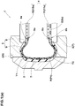
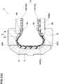
Fig. 1(a) andFig. 1(b) are a schematic cross sectional partial view of a tire vulcanizing apparatus according to one aspect of the present invention, whereinFig. 1(a) shows a state in which condensed water is not accumulated, andFig. 1(b) shows a state in which condensed water is accumulated. -
Fig. 2(a) and Fig. 2(b) are graphs showing the temperature change of the unvulcanized tire with vulcanizing time. -
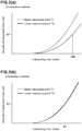
Fig. 3(a) and Fig. 3(b) are graphs showing the amount of equivalent cure unit as a function the vulcanizing time. - Embodiments of the present invention will now be described in detail in conjunction with the accompanying drawings.
- In the drawings, tire vulcanizing apparatus 1 according to the present invention comprises
a vulcanizingmold 2 for vulcanization-molding an unvulcanized tire T disposed therein,
a tire-vulcanizingbladder assembly 3 for pressing the unvulcanized tire T against the vulcanizingmold 2,
a supply means 4 for supplying a fluid G to the tire-vulcanizingbladder assembly 3, and
a discharge means 5 for discharging the fluid G in the tire-vulcanizingbladder assembly 3. - The
vulcanizing mold 2 comprises
anupper die 6 to be located on the upper side of the unvulcanized tire T, and
alower die 7 to be located on the lower side of the unvulcanized tire T.
Thevulcanizing mold 2 has a closed state in which theupper die 6 and thelower die 7 are closed as shown inFig. 1(a) , and an open state in which theupper die 6 and thelower die 7 are apart from each other in the vertical direction (not shown). Incidentally, in the open state, the unvulcanized tire T is carried therein, and the vulcanized tire T is took out therefrom. And in the closed state, the unvulcanized tire T in thevulcanizing mold 2 is vulcanization-molded.
when the unvulcanized tire T is vulcanization-molded, the tire-vulcanizingbladder assembly 3 is placed in the inner cavity of the unvulcanized tire T and inflated so as to presses the unvulcanized tire T against the vulcanizingmold 2. - The tire-vulcanizing
bladder assembly 3 comprises anoutside bladder 8 abutting on the inner surface of the unvulcanized tire T, and
at least oneinside bladder 9 disposed inside theoutside bladder 8. In this embodiment, only oneinside bladder 9 is disposed inside theoutside bladder 8. - The
outside bladder 8 has an upperfirst bead 8a secured to theupper die 6 and a lowersecond bead 8b secured to thelower die 7. It is preferable that theoutside bladder 8 is inflated with a first fluid G1 as the heated fluid G, that is, the first fluid G1 is supplied to the space P formed between theoutside bladder 8 and theinside bladder 9. - The
inside bladder 9 has an upperthird bead 9a secured to theupper die 6 and a lowerfourth bead 9b secured to thelower die 7. It is preferable that theinside bladder 9 is inflated with a second fluid G2 different from the first fluid G1, that is, the fluid G includes the first fluid G1 and the second fluid G2.
The second fluid G2 may be the heated fluid G or non-heated fluid G. - By inflating the
outside bladder 8, the tire-vulcanizingbladder assembly 3 can press the unvulcanized tire T against the vulcanizingmold 2 to mold the tire. - By inflating the
inside bladder 9, the space P formed between theoutside bladder 8 and theinside bladder 9 can be decreased in the volume. As a result, condensed water D is hard to occur in the space P.
Further, even if condensed water D occurs in the space P as shown inFig. 1(b) , the volume of the condensed water D is less, and it is easy to discharge. Therefore, in the tire vulcanizing apparatus 1 in this embodiment, the temperature decrease of the unvulcanized tire T due to the condensed water D is suppressed. Thus, physical properties of the vulcanized tire can be prevented from becoming uneven and tire performance can be improved. - In this embodiment, the supply means 4 includes a first supply means 10 for supplying the first fluid G1, and a second supply means 11 for supplying second fluid G2 as shown in
Fig. 1(a) andFig. 1(b) . - It is preferable that the first supply means 10 comprises a plurality of
first supply ports 10a for supplying the first fluid G1. Thefirst supply ports 10a are opened between the upperfirst bead 8a and the upperthird bead 9a. - In this example, the first fluid G1 inflating the
outside bladder 8 is steam S which is excellent in the heat transfer capability, and can increase the temperature of theoutside bladder 8 at a lower cost.
Incidentally, the first fluid G1 is supplied to the first supply means 10 from a steam generator (not shown). - It is preferable that the second supply means 11 comprises a plurality of
second supply ports 11a for supplying the second fluid G2. Thesecond supply ports 11a are opened in the inside of theinside bladder 9 near the lowerfourth bead 9b. - As the second fluid G2 inflating the
inside bladder 9, steam S, nitrogen gas N or hot water W can be used. In this embodiment, the second fluid G2 is nitrogen gas N supplied from a gas supply source (not shown).
The nitrogen gas N can be heated in the second supply means 11 by the use of a heater (not shown) or the first fluid G1. Incidentally, if the second fluid G2 is steam S, the second fluid G2 can be supplied from the steam generator (not shown) of the first fluid G1. - when the
outside bladder 8 and theinside bladder 9 are inflated, it is preferable that the inside pressure of theoutside bladder 8 is substantially same as the inside pressure of theinside bladder 9 in order that the space P is stably formed between theoutside bladder 8 and theinside bladder 9. - The space P between the
outside bladder 8 and theinside bladder 9 can be decreased in the volume. Thus, the volume of the first fluid G1 can be decreased accordingly. As a result, the required energy can be reduced. - By heating the second fluid G2, the first fluid G1 can be supplied with heat from the second fluid G2, therefore, even if the heat capacity is small, the occurrence of uneven temperature distribution can be prevented.
- Thus, in the tire vulcanizing apparatus 1, the temperature of the tire during vulcanization is maintained, and the vulcanizing time is reduced, therefore, the productivity can be improved.
- In this embodiment, the discharge means 5 comprises a plurality of
exhaust ports 5a for discharging the first fluid G1. Theexhaust ports 5a are located near the lowersecond bead 8b and the lowerfourth bead 9b and communicate with the space P between theoutside bladder 8 and theinside bladder 9 in order to discharge the first fluid G1 in the space P. - The second fluid G2 in the
inside bladder 9 is preferably discharged by the second supply means 11 after the tire T has been vulcanization-molded. - As described above, the
first supply ports 10a of the first supply means 10 are opened on theupper die 6 side, and theexhaust ports 5a of the discharge means 5 are opened on thelower die 7 side. Therefore, when theoutside bladder 8 and theinside bladder 9 are inflated, the space P between theoutside bladder 8 and theinside bladder 9 forms a flow path P1 in which the first fluid G1 flows.
If the steam (first fluid G1) is condensed into water D in the space P, the condensed water D flows in the flow path P1 together with the first fluid G1 and can be smoothly discharged through theexhaust ports 5a. - Next, a tire vulcanizing method according to the present invention in which an unvulcanized tire T is vulcanization-molded by the tire vulcanizing apparatus 1 shown in
Fig. 1(a) andFig. 1(b) , is described. - In the tire vulcanizing method,
by the use of theoutside bladder 8 abutting on the inner surface of the unvulcanized tire T and theinside bladder 9 disposed inside theoutside bladder 8,
the unvulcanized tire T is pressed against the vulcanizingmold 2 and vulcanization-molded. - In this embodiment, the tire vulcanizing method comprises a preparatory process S1, a first supply process S2, a discharge process S3, a second supply process S4 and a demolding process S5.
- In the tire vulcanizing method, firstly, the preparatory process S1 is carried out, wherein the unvulcanized tire T is placed in the
vulcanizing mold 2 in the open state thereof. At this stage, the tire-vulcanizingbladder assembly 3 of which the outside and insidebladders mold 2 is closed. - Next, the first supply process S2 is carried out, wherein the heated first fluid G1 is supplied between the
outside bladder 8 and theinside bladder 9, and the unvulcanized tire T is pressed against the vulcanizingmold 2 by theoutside bladder 8 so that the unvulcanized tire T is vulcanization-molded.
In the first supply process S2 in this embodiment, steam S is used as the first fluid G1 inflating theoutside bladder 8. - The discharge process S3 is a process in which the first fluid G1 between the
outside bladder 8 and theinside bladder 9 is discharged.
By the discharge process S3, the condensed water D occurred in the space P between theoutside bladder 8 and theinside bladder 9 is also discharged smoothly. - Preferably and in this embodiment, the discharge process S3 is carried out concurrently with the first supply process S2 so that the fresh first fluid G1 is continuously supplied during the unvulcanized tire T is vulcanization-molded. In this case, the feed rate of the first fluid G1 by the first supply process S2 and the discharge rate of the first fluid G1 by the discharge process S3 are controlled so that the inside pressure of the
outside bladder 8 becomes substantially constant and theoutside bladder 8 is stably inflated. - The second supply process S4 is a process in which the second fluid G2 is supplied to the inside of the
inside bladder 9 so that the space P between theoutside bladder 8 and theinside bladder 9 is reduced in the volume.
By reducing the volume of the space P, the volume of the first fluid G1 is reduced, and the required energy can be reduced. - Preferably and in this embodiment, the second supply process S4 is carried out concurrently with the first supply process S2 and the discharge process S3.
- The second fluid G2 supplied in the second supply process S4 can be heated. In this case, it is possible to transfer the heat from the second fluid G2 to the first fluid G1. As a result, it is possible to more effectively suppress the temperature decrease of the unvulcanized tire T due to the condensed water D, which helps to prevent physical properties of the vulcanized tire from becoming uneven and to improve tire performance. Further, the tire temperature during vulcanization is maintained, and the vulcanizing time can be reduced to improve the productivity.
- Next, the demolding process S5 is carried out, wherein the first fluid G1 in the space P is discharged by the discharge means 5, the second fluid G2 in the
inside bladder 9 is discharged by the second supply means 11,
thevulcanizing mold 2 is opened, and then
the vulcanized tire is took out from the vulcanizingmold 2. - while detailed description has been made of specific embodiments of the present invention, the specific embodiments should not be construed as to limit the scope of the present invention; the present invention may be embodied in various forms.
- In the above described embodiment, only one
inside bladder 9 is disposed inside theoutside bladder 8. But, it is also possible to dispose two or moreinside bladders 9 in theoutside bladder 8. In this case, theinside bladders 9 may be those separated in the up-down direction or those separated in the circumferential direction. - Unvulcanized tires (tire size 205/60R16) were vulcanization-molded according to
the above described tire vulcanizing method (embodiment method) using theoutside bladder 8 and theinside bladder 9 shown inFig. 1(a) andFig. 1(b) , and
a tire vulcanizing method (comparative method) using only theoutside bladder 9.
The temperature of the unvulcanized tire during being vulcanization-molded was measured at two measuring points T1 and T2 shown inFig. 1(a) .
The measured result of the comparative method is shown inFig. 2(a) . The measured result of the embodiment method is shown inFig. 2(b) .
As shown, in the comparative method, a significant temperature difference was caused between the measuring points T1 and T2. However, in the embodiment method, the temperature difference became substantially zero over the entire temperature range. - Further, based on each temperature change curve obtained in the comparative method and the embodiment method, the equivalent cure unit (ECU) was computed.
The result of the comparative method is shown inFig. 3(a) , and the result of the embodiment method is shown inFig. 3(b) , wherein the amount of the equivalent cure unit (ECU) is shown as a function of the vulcanizing time (index), and E1 denotes an amount of the equivalent cure unit required to complete the vulcanization of the tire.
The vulcanizing time needed to reach to E1 by the embodiment method was reduced to 87% of the vulcanizing time needed to reach to E1 by the comparative method. -
- 1
- tire vulcanizing apparatus
- 2
- vulcanizing mold
- 3
- tire-vulcanizing bladder assembly
- 4
- supply means
- 5
- discharge means
- 8
- outside bladder
- 9
- inside bladder
- T
- unvulcanized tire
- G
- fluid
- G1
- first fluid
- G2
- second fluid
Claims (10)
- A tire vulcanizing apparatus comprising:a vulcanizing mold for vulcanization-molding an unvulcanized tire,a tire-vulcanizing bladder assembly to be disposed in the inner cavity of the unvulcanized tire disposed in the vulcanizing mold, and being inflatable with a fluid so as to press the unvulcanized tire against the vulcanizing mold,a supply means for supplying the fluid to the tire-vulcanizing bladder assembly, anda discharge means for discharging the fluid from the tire-vulcanizing bladder assembly,
whereinthe tire-vulcanizing bladder assembly compresses an outside bladder for abutting on the inner surface of the unvulcanized tire, and
an inside bladder disposed inside the outside bladder, andthe fluid includes
a first fluid supplied between the outside bladder and the inside bladder, and
a second fluid supplied to the inside of the inside bladder. - The tire vulcanizing apparatus according to claim 1, wherein, when the tire-vulcanizing bladder assembly is inflated, a flow path in which the first fluid flows is formed between the outside bladder and the inside bladder.
- The tire vulcanizing apparatus according to claim 1 or 2, wherein the first fluid is steam.
- The tire vulcanizing apparatus according to claim 1, 2 or 3, wherein the second fluid is steam, nitrogen gas or hot water.
- The tire vulcanizing apparatus according to any one of claims 1-4, wherein
the vulcanizing mold comprises an upper die to be located on the upper side of the unvulcanized tire and a lower die to be located on the lower side of the unvulcanized tire,
the outside bladder comprises an upper first bead secured to the upper die and a lower second bead secured to the lower die, and
the inside bladder comprises an upper third bead secured to the upper die and a lower fourth bead secured to the lower die. - The tire vulcanizing apparatus according to claim 5, wherein
the supply means comprises a first supply means for supplying the first fluid, and a second supply means for supplying the second fluid,
the first supply means is disposed between the upper first bead and the upper third bead, and
the second supply means is disposed inside the lower fourth bead. - The tire vulcanizing apparatus according to claim 5 or 6, wherein the discharge means is disposed between the lower second bead and the lower fourth bead.
- The tire vulcanizing apparatus according to any one of claims 1-7, wherein in the tire-vulcanizing bladder assembly, only one inside bladder is disposed inside the outside bladder.
- The tire vulcanizing apparatus according to any one of claims 1-7, wherein, in the tire-vulcanizing bladder assembly, a plurality of the inside bladders are disposed inside the outside bladder.
- A tire vulcanizing method, which is for vulcanization-molding an unvulcanized tire while the unvulcanized tire disposed in a vulcanizing mold is pressed against the vulcanizing mold by the use of an outside bladder abutting on the inner surface of the unvulcanized tire, and an inside bladder disposed inside the outside bladder, and which comprises:a first supply process of supplying a first fluid between the outside bladder and the inside bladder,a discharge process of discharging the first fluid between the outside bladder and the inside bladder,a second supply process of supplying a second fluid to the inside of the inside bladder, whereinby the first supply process and the discharge process, during vulcanization-molding the unvulcanized tire, the first fluid continuously flows through a path formed between the outside bladder and the inside bladder.
Applications Claiming Priority (1)
| Application Number | Priority Date | Filing Date | Title |
|---|---|---|---|
| JP2016133498A JP6763710B2 (en) | 2016-07-05 | 2016-07-05 | Tire vulcanizer and tire vulcanization method |
Publications (2)
| Publication Number | Publication Date |
|---|---|
| EP3266599A1 true EP3266599A1 (en) | 2018-01-10 |
| EP3266599B1 EP3266599B1 (en) | 2020-09-23 |
Family
ID=59055107
Family Applications (1)
| Application Number | Title | Priority Date | Filing Date |
|---|---|---|---|
| EP17175759.4A Active EP3266599B1 (en) | 2016-07-05 | 2017-06-13 | Tire vulcanizing apparatus |
Country Status (4)
| Country | Link |
|---|---|
| US (1) | US20180009183A1 (en) |
| EP (1) | EP3266599B1 (en) |
| JP (1) | JP6763710B2 (en) |
| CN (1) | CN107571529B (en) |
Cited By (1)
| Publication number | Priority date | Publication date | Assignee | Title |
|---|---|---|---|---|
| DE102018216880A1 (en) | 2018-10-02 | 2020-06-25 | Continental Reifen Deutschland Gmbh | Tire curing device |
Families Citing this family (1)
| Publication number | Priority date | Publication date | Assignee | Title |
|---|---|---|---|---|
| CN113894974B (en) * | 2021-09-15 | 2024-04-09 | 启东捷明密封科技有限公司 | Integral vulcanization production method and system for inflatable sealing ring |
Citations (6)
| Publication number | Priority date | Publication date | Assignee | Title |
|---|---|---|---|---|
| GB2120967A (en) * | 1982-05-17 | 1983-12-14 | Sumitomo Rubber Ind | Fluid supplying and discharging apparatus for use in vulcanizing machine |
| WO2001000395A1 (en) * | 1999-06-25 | 2001-01-04 | Pirelli Pneumatici S.P.A. | Method and apparatus for moulding and curing tyres for vehicle wheels |
| JP2006027208A (en) * | 2004-07-21 | 2006-02-02 | Bridgestone Corp | Tire vulcanization method, tire vulcanization process setting method, and tire vulcanization bladder |
| JP2010110970A (en) | 2008-11-05 | 2010-05-20 | Bridgestone Corp | Tire vulcanizing apparatus and tire manufacturing method |
| JP2010131864A (en) * | 2008-12-04 | 2010-06-17 | Bridgestone Corp | Bladder |
| JP2012166405A (en) * | 2011-02-14 | 2012-09-06 | Mitsubishi Heavy Ind Ltd | Vulcanizing device, inner bladder device, and method of vulcanizing raw tire |
Family Cites Families (2)
| Publication number | Priority date | Publication date | Assignee | Title |
|---|---|---|---|---|
| US3770931A (en) * | 1972-08-02 | 1973-11-06 | Raytheon Co | Dielectric heating apparatus for tires |
| JP3668073B2 (en) * | 1999-09-29 | 2005-07-06 | 株式会社神戸製鋼所 | Tire manufacturing method |
-
2016
- 2016-07-05 JP JP2016133498A patent/JP6763710B2/en active Active
-
2017
- 2017-05-22 CN CN201710363030.2A patent/CN107571529B/en active Active
- 2017-06-13 EP EP17175759.4A patent/EP3266599B1/en active Active
- 2017-06-14 US US15/622,803 patent/US20180009183A1/en not_active Abandoned
Patent Citations (6)
| Publication number | Priority date | Publication date | Assignee | Title |
|---|---|---|---|---|
| GB2120967A (en) * | 1982-05-17 | 1983-12-14 | Sumitomo Rubber Ind | Fluid supplying and discharging apparatus for use in vulcanizing machine |
| WO2001000395A1 (en) * | 1999-06-25 | 2001-01-04 | Pirelli Pneumatici S.P.A. | Method and apparatus for moulding and curing tyres for vehicle wheels |
| JP2006027208A (en) * | 2004-07-21 | 2006-02-02 | Bridgestone Corp | Tire vulcanization method, tire vulcanization process setting method, and tire vulcanization bladder |
| JP2010110970A (en) | 2008-11-05 | 2010-05-20 | Bridgestone Corp | Tire vulcanizing apparatus and tire manufacturing method |
| JP2010131864A (en) * | 2008-12-04 | 2010-06-17 | Bridgestone Corp | Bladder |
| JP2012166405A (en) * | 2011-02-14 | 2012-09-06 | Mitsubishi Heavy Ind Ltd | Vulcanizing device, inner bladder device, and method of vulcanizing raw tire |
Cited By (1)
| Publication number | Priority date | Publication date | Assignee | Title |
|---|---|---|---|---|
| DE102018216880A1 (en) | 2018-10-02 | 2020-06-25 | Continental Reifen Deutschland Gmbh | Tire curing device |
Also Published As
| Publication number | Publication date |
|---|---|
| EP3266599B1 (en) | 2020-09-23 |
| JP2018001652A (en) | 2018-01-11 |
| US20180009183A1 (en) | 2018-01-11 |
| CN107571529B (en) | 2021-05-11 |
| JP6763710B2 (en) | 2020-09-30 |
| CN107571529A (en) | 2018-01-12 |
Similar Documents
| Publication | Publication Date | Title |
|---|---|---|
| EP2535173B1 (en) | Tire vulcanizer and tire vulcanizing method | |
| US9738043B2 (en) | Tire vulcanizing apparatus | |
| KR102044811B1 (en) | Method and apparatus for vulcanizing a tyre | |
| EP3266599B1 (en) | Tire vulcanizing apparatus | |
| CN107866928B (en) | Tire vulcanizing device | |
| JP2003340824A (en) | Tire vulcanization molding method and tire molding die | |
| CN111716604B (en) | Method and apparatus for manufacturing pneumatic tire | |
| JP2016055528A (en) | Tire vulcanizing apparatus and method for vulcanizing tire using the same | |
| JP6617437B2 (en) | Method and apparatus for manufacturing tire vulcanizing bladder | |
| IT202200026979A1 (en) | “Apparatus for vulcanizing and molding tires and method for preheating circumferential sectors in an apparatus for vulcanizing and molding tires” | |
| JP6926790B2 (en) | Tire vulcanization method and tire vulcanization equipment | |
| JP2015168122A (en) | Bladder for tire vulcanization and method for measuring distortion of bladder for tire vulcanization | |
| JP5345461B2 (en) | Tire vulcanizing apparatus and tire manufacturing method | |
| JP5929488B2 (en) | Pneumatic tire vulcanizing apparatus and method | |
| KR101160235B1 (en) | Tire vulcanizer | |
| US20230027451A1 (en) | Container for tire vulcanizer | |
| KR20140136153A (en) | Method and Apparatus of Post Cure Inflation for Tire | |
| JP5974680B2 (en) | Tire manufacturing method and tire vulcanization bladder pre-shaping device | |
| KR101425038B1 (en) | multi pressure tire bladder | |
| CN108927925A (en) | Vulcanization capsule, vulcanization plant and vulcanization process | |
| JP7488453B2 (en) | Manufacturing method and manufacturing device for pneumatic tire | |
| JP2009208400A (en) | Tire production method and production equipment | |
| JP2010030067A (en) | Vulcanization bladder and method for vulcanizing/molding tire using the same | |
| JP2008126495A (en) | Tire vulcanizing bladder and method for vulcanizing tire using the bladder | |
| JP6763159B2 (en) | Tire vulcanization method |
Legal Events
| Date | Code | Title | Description |
|---|---|---|---|
| PUAI | Public reference made under article 153(3) epc to a published international application that has entered the european phase |
Free format text: ORIGINAL CODE: 0009012 |
|
| STAA | Information on the status of an ep patent application or granted ep patent |
Free format text: STATUS: THE APPLICATION HAS BEEN PUBLISHED |
|
| AK | Designated contracting states |
Kind code of ref document: A1 Designated state(s): AL AT BE BG CH CY CZ DE DK EE ES FI FR GB GR HR HU IE IS IT LI LT LU LV MC MK MT NL NO PL PT RO RS SE SI SK SM TR |
|
| AX | Request for extension of the european patent |
Extension state: BA ME |
|
| STAA | Information on the status of an ep patent application or granted ep patent |
Free format text: STATUS: REQUEST FOR EXAMINATION WAS MADE |
|
| 17P | Request for examination filed |
Effective date: 20180524 |
|
| RBV | Designated contracting states (corrected) |
Designated state(s): AL AT BE BG CH CY CZ DE DK EE ES FI FR GB GR HR HU IE IS IT LI LT LU LV MC MK MT NL NO PL PT RO RS SE SI SK SM TR |
|
| GRAP | Despatch of communication of intention to grant a patent |
Free format text: ORIGINAL CODE: EPIDOSNIGR1 |
|
| STAA | Information on the status of an ep patent application or granted ep patent |
Free format text: STATUS: GRANT OF PATENT IS INTENDED |
|
| INTG | Intention to grant announced |
Effective date: 20200703 |
|
| RIN1 | Information on inventor provided before grant (corrected) |
Inventor name: TANAKA, TAKASHI Inventor name: HAYASHI, KAZUO |
|
| GRAS | Grant fee paid |
Free format text: ORIGINAL CODE: EPIDOSNIGR3 |
|
| GRAA | (expected) grant |
Free format text: ORIGINAL CODE: 0009210 |
|
| STAA | Information on the status of an ep patent application or granted ep patent |
Free format text: STATUS: THE PATENT HAS BEEN GRANTED |
|
| AK | Designated contracting states |
Kind code of ref document: B1 Designated state(s): AL AT BE BG CH CY CZ DE DK EE ES FI FR GB GR HR HU IE IS IT LI LT LU LV MC MK MT NL NO PL PT RO RS SE SI SK SM TR |
|
| REG | Reference to a national code |
Ref country code: GB Ref legal event code: FG4D |
|
| REG | Reference to a national code |
Ref country code: CH Ref legal event code: EP |
|
| REG | Reference to a national code |
Ref country code: IE Ref legal event code: FG4D |
|
| REG | Reference to a national code |
Ref country code: DE Ref legal event code: R096 Ref document number: 602017023996 Country of ref document: DE Ref country code: AT Ref legal event code: REF Ref document number: 1315966 Country of ref document: AT Kind code of ref document: T Effective date: 20201015 |
|
| PG25 | Lapsed in a contracting state [announced via postgrant information from national office to epo] |
Ref country code: BG Free format text: LAPSE BECAUSE OF FAILURE TO SUBMIT A TRANSLATION OF THE DESCRIPTION OR TO PAY THE FEE WITHIN THE PRESCRIBED TIME-LIMIT Effective date: 20201223 Ref country code: GR Free format text: LAPSE BECAUSE OF FAILURE TO SUBMIT A TRANSLATION OF THE DESCRIPTION OR TO PAY THE FEE WITHIN THE PRESCRIBED TIME-LIMIT Effective date: 20201224 Ref country code: NO Free format text: LAPSE BECAUSE OF FAILURE TO SUBMIT A TRANSLATION OF THE DESCRIPTION OR TO PAY THE FEE WITHIN THE PRESCRIBED TIME-LIMIT Effective date: 20201223 Ref country code: FI Free format text: LAPSE BECAUSE OF FAILURE TO SUBMIT A TRANSLATION OF THE DESCRIPTION OR TO PAY THE FEE WITHIN THE PRESCRIBED TIME-LIMIT Effective date: 20200923 Ref country code: SE Free format text: LAPSE BECAUSE OF FAILURE TO SUBMIT A TRANSLATION OF THE DESCRIPTION OR TO PAY THE FEE WITHIN THE PRESCRIBED TIME-LIMIT Effective date: 20200923 Ref country code: HR Free format text: LAPSE BECAUSE OF FAILURE TO SUBMIT A TRANSLATION OF THE DESCRIPTION OR TO PAY THE FEE WITHIN THE PRESCRIBED TIME-LIMIT Effective date: 20200923 |
|
| REG | Reference to a national code |
Ref country code: AT Ref legal event code: MK05 Ref document number: 1315966 Country of ref document: AT Kind code of ref document: T Effective date: 20200923 |
|
| PG25 | Lapsed in a contracting state [announced via postgrant information from national office to epo] |
Ref country code: LV Free format text: LAPSE BECAUSE OF FAILURE TO SUBMIT A TRANSLATION OF THE DESCRIPTION OR TO PAY THE FEE WITHIN THE PRESCRIBED TIME-LIMIT Effective date: 20200923 Ref country code: RS Free format text: LAPSE BECAUSE OF FAILURE TO SUBMIT A TRANSLATION OF THE DESCRIPTION OR TO PAY THE FEE WITHIN THE PRESCRIBED TIME-LIMIT Effective date: 20200923 |
|
| REG | Reference to a national code |
Ref country code: NL Ref legal event code: MP Effective date: 20200923 |
|
| REG | Reference to a national code |
Ref country code: LT Ref legal event code: MG4D |
|
| PG25 | Lapsed in a contracting state [announced via postgrant information from national office to epo] |
Ref country code: EE Free format text: LAPSE BECAUSE OF FAILURE TO SUBMIT A TRANSLATION OF THE DESCRIPTION OR TO PAY THE FEE WITHIN THE PRESCRIBED TIME-LIMIT Effective date: 20200923 Ref country code: SM Free format text: LAPSE BECAUSE OF FAILURE TO SUBMIT A TRANSLATION OF THE DESCRIPTION OR TO PAY THE FEE WITHIN THE PRESCRIBED TIME-LIMIT Effective date: 20200923 Ref country code: LT Free format text: LAPSE BECAUSE OF FAILURE TO SUBMIT A TRANSLATION OF THE DESCRIPTION OR TO PAY THE FEE WITHIN THE PRESCRIBED TIME-LIMIT Effective date: 20200923 Ref country code: CZ Free format text: LAPSE BECAUSE OF FAILURE TO SUBMIT A TRANSLATION OF THE DESCRIPTION OR TO PAY THE FEE WITHIN THE PRESCRIBED TIME-LIMIT Effective date: 20200923 Ref country code: RO Free format text: LAPSE BECAUSE OF FAILURE TO SUBMIT A TRANSLATION OF THE DESCRIPTION OR TO PAY THE FEE WITHIN THE PRESCRIBED TIME-LIMIT Effective date: 20200923 Ref country code: PT Free format text: LAPSE BECAUSE OF FAILURE TO SUBMIT A TRANSLATION OF THE DESCRIPTION OR TO PAY THE FEE WITHIN THE PRESCRIBED TIME-LIMIT Effective date: 20210125 |
|
| PG25 | Lapsed in a contracting state [announced via postgrant information from national office to epo] |
Ref country code: ES Free format text: LAPSE BECAUSE OF FAILURE TO SUBMIT A TRANSLATION OF THE DESCRIPTION OR TO PAY THE FEE WITHIN THE PRESCRIBED TIME-LIMIT Effective date: 20200923 Ref country code: AL Free format text: LAPSE BECAUSE OF FAILURE TO SUBMIT A TRANSLATION OF THE DESCRIPTION OR TO PAY THE FEE WITHIN THE PRESCRIBED TIME-LIMIT Effective date: 20200923 Ref country code: AT Free format text: LAPSE BECAUSE OF FAILURE TO SUBMIT A TRANSLATION OF THE DESCRIPTION OR TO PAY THE FEE WITHIN THE PRESCRIBED TIME-LIMIT Effective date: 20200923 Ref country code: PL Free format text: LAPSE BECAUSE OF FAILURE TO SUBMIT A TRANSLATION OF THE DESCRIPTION OR TO PAY THE FEE WITHIN THE PRESCRIBED TIME-LIMIT Effective date: 20200923 Ref country code: IS Free format text: LAPSE BECAUSE OF FAILURE TO SUBMIT A TRANSLATION OF THE DESCRIPTION OR TO PAY THE FEE WITHIN THE PRESCRIBED TIME-LIMIT Effective date: 20210123 |
|
| REG | Reference to a national code |
Ref country code: DE Ref legal event code: R097 Ref document number: 602017023996 Country of ref document: DE |
|
| PG25 | Lapsed in a contracting state [announced via postgrant information from national office to epo] |
Ref country code: SK Free format text: LAPSE BECAUSE OF FAILURE TO SUBMIT A TRANSLATION OF THE DESCRIPTION OR TO PAY THE FEE WITHIN THE PRESCRIBED TIME-LIMIT Effective date: 20200923 |
|
| PLBE | No opposition filed within time limit |
Free format text: ORIGINAL CODE: 0009261 |
|
| STAA | Information on the status of an ep patent application or granted ep patent |
Free format text: STATUS: NO OPPOSITION FILED WITHIN TIME LIMIT |
|
| PG25 | Lapsed in a contracting state [announced via postgrant information from national office to epo] |
Ref country code: SI Free format text: LAPSE BECAUSE OF FAILURE TO SUBMIT A TRANSLATION OF THE DESCRIPTION OR TO PAY THE FEE WITHIN THE PRESCRIBED TIME-LIMIT Effective date: 20200923 Ref country code: DK Free format text: LAPSE BECAUSE OF FAILURE TO SUBMIT A TRANSLATION OF THE DESCRIPTION OR TO PAY THE FEE WITHIN THE PRESCRIBED TIME-LIMIT Effective date: 20200923 |
|
| 26N | No opposition filed |
Effective date: 20210624 |
|
| PG25 | Lapsed in a contracting state [announced via postgrant information from national office to epo] |
Ref country code: IT Free format text: LAPSE BECAUSE OF FAILURE TO SUBMIT A TRANSLATION OF THE DESCRIPTION OR TO PAY THE FEE WITHIN THE PRESCRIBED TIME-LIMIT Effective date: 20200923 |
|
| PG25 | Lapsed in a contracting state [announced via postgrant information from national office to epo] |
Ref country code: MC Free format text: LAPSE BECAUSE OF FAILURE TO SUBMIT A TRANSLATION OF THE DESCRIPTION OR TO PAY THE FEE WITHIN THE PRESCRIBED TIME-LIMIT Effective date: 20200923 |
|
| REG | Reference to a national code |
Ref country code: CH Ref legal event code: PL |
|
| GBPC | Gb: european patent ceased through non-payment of renewal fee |
Effective date: 20210613 |
|
| REG | Reference to a national code |
Ref country code: BE Ref legal event code: MM Effective date: 20210630 |
|
| PG25 | Lapsed in a contracting state [announced via postgrant information from national office to epo] |
Ref country code: LU Free format text: LAPSE BECAUSE OF NON-PAYMENT OF DUE FEES Effective date: 20210613 |
|
| PG25 | Lapsed in a contracting state [announced via postgrant information from national office to epo] |
Ref country code: LI Free format text: LAPSE BECAUSE OF NON-PAYMENT OF DUE FEES Effective date: 20210630 Ref country code: IE Free format text: LAPSE BECAUSE OF NON-PAYMENT OF DUE FEES Effective date: 20210613 Ref country code: GB Free format text: LAPSE BECAUSE OF NON-PAYMENT OF DUE FEES Effective date: 20210613 Ref country code: CH Free format text: LAPSE BECAUSE OF NON-PAYMENT OF DUE FEES Effective date: 20210630 |
|
| PG25 | Lapsed in a contracting state [announced via postgrant information from national office to epo] |
Ref country code: BE Free format text: LAPSE BECAUSE OF NON-PAYMENT OF DUE FEES Effective date: 20210630 |
|
| PG25 | Lapsed in a contracting state [announced via postgrant information from national office to epo] |
Ref country code: HU Free format text: LAPSE BECAUSE OF FAILURE TO SUBMIT A TRANSLATION OF THE DESCRIPTION OR TO PAY THE FEE WITHIN THE PRESCRIBED TIME-LIMIT; INVALID AB INITIO Effective date: 20170613 |
|
| P01 | Opt-out of the competence of the unified patent court (upc) registered |
Effective date: 20230510 |
|
| PG25 | Lapsed in a contracting state [announced via postgrant information from national office to epo] |
Ref country code: NL Free format text: LAPSE BECAUSE OF NON-PAYMENT OF DUE FEES Effective date: 20200923 Ref country code: CY Free format text: LAPSE BECAUSE OF FAILURE TO SUBMIT A TRANSLATION OF THE DESCRIPTION OR TO PAY THE FEE WITHIN THE PRESCRIBED TIME-LIMIT Effective date: 20200923 |
|
| PG25 | Lapsed in a contracting state [announced via postgrant information from national office to epo] |
Ref country code: MK Free format text: LAPSE BECAUSE OF FAILURE TO SUBMIT A TRANSLATION OF THE DESCRIPTION OR TO PAY THE FEE WITHIN THE PRESCRIBED TIME-LIMIT Effective date: 20200923 |
|
| PG25 | Lapsed in a contracting state [announced via postgrant information from national office to epo] |
Ref country code: TR Free format text: LAPSE BECAUSE OF FAILURE TO SUBMIT A TRANSLATION OF THE DESCRIPTION OR TO PAY THE FEE WITHIN THE PRESCRIBED TIME-LIMIT Effective date: 20200923 |
|
| PG25 | Lapsed in a contracting state [announced via postgrant information from national office to epo] |
Ref country code: MT Free format text: LAPSE BECAUSE OF FAILURE TO SUBMIT A TRANSLATION OF THE DESCRIPTION OR TO PAY THE FEE WITHIN THE PRESCRIBED TIME-LIMIT Effective date: 20200923 |
|
| PGFP | Annual fee paid to national office [announced via postgrant information from national office to epo] |
Ref country code: DE Payment date: 20250429 Year of fee payment: 9 |
|
| PGFP | Annual fee paid to national office [announced via postgrant information from national office to epo] |
Ref country code: FR Payment date: 20250508 Year of fee payment: 9 |