EP3266479A1 - Injection device - Google Patents
Injection device Download PDFInfo
- Publication number
- EP3266479A1 EP3266479A1 EP17185922.6A EP17185922A EP3266479A1 EP 3266479 A1 EP3266479 A1 EP 3266479A1 EP 17185922 A EP17185922 A EP 17185922A EP 3266479 A1 EP3266479 A1 EP 3266479A1
- Authority
- EP
- European Patent Office
- Prior art keywords
- syringe
- shield
- assembly
- plunger
- drive assembly
- Prior art date
- Legal status (The legal status is an assumption and is not a legal conclusion. Google has not performed a legal analysis and makes no representation as to the accuracy of the status listed.)
- Withdrawn
Links
Images
Classifications
-
- A—HUMAN NECESSITIES
- A61—MEDICAL OR VETERINARY SCIENCE; HYGIENE
- A61M—DEVICES FOR INTRODUCING MEDIA INTO, OR ONTO, THE BODY; DEVICES FOR TRANSDUCING BODY MEDIA OR FOR TAKING MEDIA FROM THE BODY; DEVICES FOR PRODUCING OR ENDING SLEEP OR STUPOR
- A61M5/00—Devices for bringing media into the body in a subcutaneous, intra-vascular or intramuscular way; Accessories therefor, e.g. filling or cleaning devices, arm-rests
- A61M5/178—Syringes
- A61M5/31—Details
- A61M5/32—Needles; Details of needles pertaining to their connection with syringe or hub; Accessories for bringing the needle into, or holding the needle on, the body; Devices for protection of needles
- A61M5/3205—Apparatus for removing or disposing of used needles or syringes, e.g. containers; Means for protection against accidental injuries from used needles
-
- A—HUMAN NECESSITIES
- A61—MEDICAL OR VETERINARY SCIENCE; HYGIENE
- A61M—DEVICES FOR INTRODUCING MEDIA INTO, OR ONTO, THE BODY; DEVICES FOR TRANSDUCING BODY MEDIA OR FOR TAKING MEDIA FROM THE BODY; DEVICES FOR PRODUCING OR ENDING SLEEP OR STUPOR
- A61M5/00—Devices for bringing media into the body in a subcutaneous, intra-vascular or intramuscular way; Accessories therefor, e.g. filling or cleaning devices, arm-rests
- A61M5/178—Syringes
- A61M5/20—Automatic syringes, e.g. with automatically actuated piston rod, with automatic needle injection, filling automatically
- A61M5/2033—Spring-loaded one-shot injectors with or without automatic needle insertion
-
- A—HUMAN NECESSITIES
- A61—MEDICAL OR VETERINARY SCIENCE; HYGIENE
- A61M—DEVICES FOR INTRODUCING MEDIA INTO, OR ONTO, THE BODY; DEVICES FOR TRANSDUCING BODY MEDIA OR FOR TAKING MEDIA FROM THE BODY; DEVICES FOR PRODUCING OR ENDING SLEEP OR STUPOR
- A61M5/00—Devices for bringing media into the body in a subcutaneous, intra-vascular or intramuscular way; Accessories therefor, e.g. filling or cleaning devices, arm-rests
- A61M5/178—Syringes
- A61M5/24—Ampoule syringes, i.e. syringes with needle for use in combination with replaceable ampoules or carpules, e.g. automatic
-
- A—HUMAN NECESSITIES
- A61—MEDICAL OR VETERINARY SCIENCE; HYGIENE
- A61M—DEVICES FOR INTRODUCING MEDIA INTO, OR ONTO, THE BODY; DEVICES FOR TRANSDUCING BODY MEDIA OR FOR TAKING MEDIA FROM THE BODY; DEVICES FOR PRODUCING OR ENDING SLEEP OR STUPOR
- A61M5/00—Devices for bringing media into the body in a subcutaneous, intra-vascular or intramuscular way; Accessories therefor, e.g. filling or cleaning devices, arm-rests
- A61M5/178—Syringes
- A61M5/31—Details
- A61M5/32—Needles; Details of needles pertaining to their connection with syringe or hub; Accessories for bringing the needle into, or holding the needle on, the body; Devices for protection of needles
- A61M5/3205—Apparatus for removing or disposing of used needles or syringes, e.g. containers; Means for protection against accidental injuries from used needles
- A61M5/321—Means for protection against accidental injuries by used needles
- A61M5/3243—Means for protection against accidental injuries by used needles being axially-extensible, e.g. protective sleeves coaxially slidable on the syringe barrel
- A61M5/326—Fully automatic sleeve extension, i.e. in which triggering of the sleeve does not require a deliberate action by the user
-
- A—HUMAN NECESSITIES
- A61—MEDICAL OR VETERINARY SCIENCE; HYGIENE
- A61M—DEVICES FOR INTRODUCING MEDIA INTO, OR ONTO, THE BODY; DEVICES FOR TRANSDUCING BODY MEDIA OR FOR TAKING MEDIA FROM THE BODY; DEVICES FOR PRODUCING OR ENDING SLEEP OR STUPOR
- A61M5/00—Devices for bringing media into the body in a subcutaneous, intra-vascular or intramuscular way; Accessories therefor, e.g. filling or cleaning devices, arm-rests
- A61M5/178—Syringes
- A61M5/31—Details
- A61M5/32—Needles; Details of needles pertaining to their connection with syringe or hub; Accessories for bringing the needle into, or holding the needle on, the body; Devices for protection of needles
- A61M5/3205—Apparatus for removing or disposing of used needles or syringes, e.g. containers; Means for protection against accidental injuries from used needles
- A61M5/321—Means for protection against accidental injuries by used needles
- A61M5/3243—Means for protection against accidental injuries by used needles being axially-extensible, e.g. protective sleeves coaxially slidable on the syringe barrel
- A61M5/3271—Means for protection against accidental injuries by used needles being axially-extensible, e.g. protective sleeves coaxially slidable on the syringe barrel with guiding tracks for controlled sliding of needle protective sleeve from needle exposing to needle covering position
- A61M5/3272—Means for protection against accidental injuries by used needles being axially-extensible, e.g. protective sleeves coaxially slidable on the syringe barrel with guiding tracks for controlled sliding of needle protective sleeve from needle exposing to needle covering position having projections following labyrinth paths
-
- A—HUMAN NECESSITIES
- A61—MEDICAL OR VETERINARY SCIENCE; HYGIENE
- A61M—DEVICES FOR INTRODUCING MEDIA INTO, OR ONTO, THE BODY; DEVICES FOR TRANSDUCING BODY MEDIA OR FOR TAKING MEDIA FROM THE BODY; DEVICES FOR PRODUCING OR ENDING SLEEP OR STUPOR
- A61M5/00—Devices for bringing media into the body in a subcutaneous, intra-vascular or intramuscular way; Accessories therefor, e.g. filling or cleaning devices, arm-rests
- A61M5/178—Syringes
- A61M5/20—Automatic syringes, e.g. with automatically actuated piston rod, with automatic needle injection, filling automatically
- A61M2005/206—With automatic needle insertion
-
- A—HUMAN NECESSITIES
- A61—MEDICAL OR VETERINARY SCIENCE; HYGIENE
- A61M—DEVICES FOR INTRODUCING MEDIA INTO, OR ONTO, THE BODY; DEVICES FOR TRANSDUCING BODY MEDIA OR FOR TAKING MEDIA FROM THE BODY; DEVICES FOR PRODUCING OR ENDING SLEEP OR STUPOR
- A61M5/00—Devices for bringing media into the body in a subcutaneous, intra-vascular or intramuscular way; Accessories therefor, e.g. filling or cleaning devices, arm-rests
- A61M5/178—Syringes
- A61M5/20—Automatic syringes, e.g. with automatically actuated piston rod, with automatic needle injection, filling automatically
- A61M2005/2073—Automatic syringes, e.g. with automatically actuated piston rod, with automatic needle injection, filling automatically preventing premature release, e.g. by making use of a safety lock
-
- A—HUMAN NECESSITIES
- A61—MEDICAL OR VETERINARY SCIENCE; HYGIENE
- A61M—DEVICES FOR INTRODUCING MEDIA INTO, OR ONTO, THE BODY; DEVICES FOR TRANSDUCING BODY MEDIA OR FOR TAKING MEDIA FROM THE BODY; DEVICES FOR PRODUCING OR ENDING SLEEP OR STUPOR
- A61M5/00—Devices for bringing media into the body in a subcutaneous, intra-vascular or intramuscular way; Accessories therefor, e.g. filling or cleaning devices, arm-rests
- A61M5/178—Syringes
- A61M5/24—Ampoule syringes, i.e. syringes with needle for use in combination with replaceable ampoules or carpules, e.g. automatic
- A61M2005/2485—Ampoule holder connected to rest of syringe
- A61M2005/2492—Ampoule holder connected to rest of syringe via snap connection
-
- A—HUMAN NECESSITIES
- A61—MEDICAL OR VETERINARY SCIENCE; HYGIENE
- A61M—DEVICES FOR INTRODUCING MEDIA INTO, OR ONTO, THE BODY; DEVICES FOR TRANSDUCING BODY MEDIA OR FOR TAKING MEDIA FROM THE BODY; DEVICES FOR PRODUCING OR ENDING SLEEP OR STUPOR
- A61M5/00—Devices for bringing media into the body in a subcutaneous, intra-vascular or intramuscular way; Accessories therefor, e.g. filling or cleaning devices, arm-rests
- A61M5/178—Syringes
- A61M5/31—Details
- A61M5/315—Pistons; Piston-rods; Guiding, blocking or restricting the movement of the rod or piston; Appliances on the rod for facilitating dosing ; Dosing mechanisms
- A61M5/31501—Means for blocking or restricting the movement of the rod or piston
- A61M2005/31508—Means for blocking or restricting the movement of the rod or piston provided on the piston-rod
-
- A—HUMAN NECESSITIES
- A61—MEDICAL OR VETERINARY SCIENCE; HYGIENE
- A61M—DEVICES FOR INTRODUCING MEDIA INTO, OR ONTO, THE BODY; DEVICES FOR TRANSDUCING BODY MEDIA OR FOR TAKING MEDIA FROM THE BODY; DEVICES FOR PRODUCING OR ENDING SLEEP OR STUPOR
- A61M5/00—Devices for bringing media into the body in a subcutaneous, intra-vascular or intramuscular way; Accessories therefor, e.g. filling or cleaning devices, arm-rests
- A61M5/178—Syringes
- A61M5/31—Details
- A61M5/315—Pistons; Piston-rods; Guiding, blocking or restricting the movement of the rod or piston; Appliances on the rod for facilitating dosing ; Dosing mechanisms
- A61M5/31501—Means for blocking or restricting the movement of the rod or piston
- A61M2005/3151—Means for blocking or restricting the movement of the rod or piston by friction
-
- A—HUMAN NECESSITIES
- A61—MEDICAL OR VETERINARY SCIENCE; HYGIENE
- A61M—DEVICES FOR INTRODUCING MEDIA INTO, OR ONTO, THE BODY; DEVICES FOR TRANSDUCING BODY MEDIA OR FOR TAKING MEDIA FROM THE BODY; DEVICES FOR PRODUCING OR ENDING SLEEP OR STUPOR
- A61M5/00—Devices for bringing media into the body in a subcutaneous, intra-vascular or intramuscular way; Accessories therefor, e.g. filling or cleaning devices, arm-rests
- A61M5/178—Syringes
- A61M5/31—Details
- A61M5/32—Needles; Details of needles pertaining to their connection with syringe or hub; Accessories for bringing the needle into, or holding the needle on, the body; Devices for protection of needles
- A61M5/3205—Apparatus for removing or disposing of used needles or syringes, e.g. containers; Means for protection against accidental injuries from used needles
- A61M5/321—Means for protection against accidental injuries by used needles
- A61M5/3243—Means for protection against accidental injuries by used needles being axially-extensible, e.g. protective sleeves coaxially slidable on the syringe barrel
- A61M5/3245—Constructional features thereof, e.g. to improve manipulation or functioning
- A61M2005/3254—Shielding of proximal needles, e.g. for pen needles
-
- A—HUMAN NECESSITIES
- A61—MEDICAL OR VETERINARY SCIENCE; HYGIENE
- A61M—DEVICES FOR INTRODUCING MEDIA INTO, OR ONTO, THE BODY; DEVICES FOR TRANSDUCING BODY MEDIA OR FOR TAKING MEDIA FROM THE BODY; DEVICES FOR PRODUCING OR ENDING SLEEP OR STUPOR
- A61M5/00—Devices for bringing media into the body in a subcutaneous, intra-vascular or intramuscular way; Accessories therefor, e.g. filling or cleaning devices, arm-rests
- A61M5/178—Syringes
- A61M5/31—Details
- A61M5/315—Pistons; Piston-rods; Guiding, blocking or restricting the movement of the rod or piston; Appliances on the rod for facilitating dosing ; Dosing mechanisms
- A61M5/31511—Piston or piston-rod constructions, e.g. connection of piston with piston-rod
- A61M5/31513—Piston constructions to improve sealing or sliding
-
- A—HUMAN NECESSITIES
- A61—MEDICAL OR VETERINARY SCIENCE; HYGIENE
- A61M—DEVICES FOR INTRODUCING MEDIA INTO, OR ONTO, THE BODY; DEVICES FOR TRANSDUCING BODY MEDIA OR FOR TAKING MEDIA FROM THE BODY; DEVICES FOR PRODUCING OR ENDING SLEEP OR STUPOR
- A61M5/00—Devices for bringing media into the body in a subcutaneous, intra-vascular or intramuscular way; Accessories therefor, e.g. filling or cleaning devices, arm-rests
- A61M5/178—Syringes
- A61M5/31—Details
- A61M5/315—Pistons; Piston-rods; Guiding, blocking or restricting the movement of the rod or piston; Appliances on the rod for facilitating dosing ; Dosing mechanisms
- A61M5/31565—Administration mechanisms, i.e. constructional features, modes of administering a dose
- A61M5/31566—Means improving security or handling thereof
- A61M5/31571—Means preventing accidental administration
-
- A—HUMAN NECESSITIES
- A61—MEDICAL OR VETERINARY SCIENCE; HYGIENE
- A61M—DEVICES FOR INTRODUCING MEDIA INTO, OR ONTO, THE BODY; DEVICES FOR TRANSDUCING BODY MEDIA OR FOR TAKING MEDIA FROM THE BODY; DEVICES FOR PRODUCING OR ENDING SLEEP OR STUPOR
- A61M5/00—Devices for bringing media into the body in a subcutaneous, intra-vascular or intramuscular way; Accessories therefor, e.g. filling or cleaning devices, arm-rests
- A61M5/178—Syringes
- A61M5/31—Details
- A61M5/32—Needles; Details of needles pertaining to their connection with syringe or hub; Accessories for bringing the needle into, or holding the needle on, the body; Devices for protection of needles
- A61M5/3202—Devices for protection of the needle before use, e.g. caps
- A61M5/3204—Needle cap remover, i.e. devices to dislodge protection cover from needle or needle hub, e.g. deshielding devices
Definitions
- the syringe assembly is coupled to the drive assembly by offering up the tongues 14 to the locking recesses 16 and pushing the syringe assembly rearwardly to effect a snap fit.
- the main body portion 48 of the drive assembly 10 has a tooth 50 extending rearwardly and inwardly from each locking recess 16 and designed so that when the coupling tongues 14 pass through the recesses 16, the ramps 28 snap fit behind the teeth 50 to lock the syringe assembly 12 against forward movement.
Abstract

Description
- This invention relates to injection devices and, in particular, but not exclusively, to autoinjection devices.
- Many autoinjection devices are single use, disposable devices. With the growing awareness of the environmental impact of such devices once used, there is a desire to make part of such devices reuseable and to reduce the proportion of the device that is single use and disposable. Furthermore, it is desirable to design the disposable, single use, part of the device so that it is readily adapted for recycling.
- Accordingly, in one aspect, this invention provides a syringe assembly comprising:
- a syringe having a body and a needle, and
- a shield slideably mounted around said syringe for telescopic movement between a retracted position in which the syringe needle is exposed in use and an extended position in which the needle is at least partially shrouded by said shield,
- wherein said syringe body has a feature thereon which cooperates with an associated feature on the shield to control relative movement thereof.
- Advantageously said syringe body and said feature are of moulded plastics material. Preferably said cooperating features limit the extent of telescopic movement of the syringe and the shield, and further may be operable releasably to latch said shield in a forward position relative to the syringe.
- The cooperating features may typically comprise a projection on one of the syringe or shield, cooperating with a control slot on the other thereof. The slot may be provided at one end region with a latch recess for releasably retaining said projection, and the wall of the slot, at least in the region of said latch recess, is preferably resiliently deformable to allow said projection to snap out of said recess to allow said shield to move rearwardly relative to the syringe. There may be a locking member engageable adjacent or near said slot for inhibiting resilient movement of said latch recess to prevent release of said projection, and the locking member may be engageable by being longitudinally slideable into a locking slot provided alongside said control slot. The locking member may carry at its forward end a cap for closing the forward end of said shield, when applied to the forward end of said shield, and with the locking member slid longitudinally into said locking slot. Where as is common the syringe includes a boot covering said needle prior to use, the cap conveniently includes means for engaging said boot when said cap is applied to said shield, such that removal of said cap removes said boot.
- Where said syringe assembly is adapted to be releasably coupled in use to the drive assembly of an autoinjection device in which the drive assembly includes a drive for expelling a dose from the syringe, a trigger for releasing said drive, and a safety arrangement for preventing inadvertent actuation of said drive, said locking member is preferably arranged to release said safety arrangement and/or unlock said safety arrangement for subsequent release, when said locking member is removed from said shield.
- A number of different configurations are possible, but the syringe may typically be carried inside said shield by direct sliding engagement therebetween.
- In order to reduce the number of parts and amount of material that is required to be disposed of in a multi-use autoinjector arrangement, of the type in which a syringe assembly as described is adapted to be releasably coupled in use to the drive assembly of the autoinjector device, the syringe assembly is preferably coupled to said drive assembly in use by interengagement of a portion of said shield with said drive assembly, so that the shield acts as both shield and container, thereby obviating the need for a separate container so that just the syringe and the shield are disposed of post use. The shield may include one or more features for snap engagement in use with an associated one or more features on said drive assembly. To automate ejection the syringe and shield after use, said drive may be adapted to uncouple said shield from said drive assembly on approaching or reaching the forwardmost extent of movement.
- The invention extends to an autoinjection device including a removable syringe as set out above.
- In order to provide simple, safe and reliable operation, and thereby a device whose use is intuitive yet inherently safe, the inventors have designed an autoinjection device in which a number of locks keep the device in a safe condition prior to use, but are all released by removal of a single element.
- Accordingly, in another aspect of this invention provides an autoinjection device comprising:
- a syringe having a needle which prior to injection carries a boot;
- a shield movable relative to said syringe between an extended position in which the needle is at least partially shrouded and a retracted position in which the needle is exposed;
- a drive assembly for expelling a dose from the syringe;
- a trigger for actuating said drive assembly;
- a safety arrangement for preventing inadvertent actuation of said drive assembly, and
- a boot remover applied to the forward end of said autoinjector and adapted to engage said boot, said boot remover being arranged to prevent movement of said syringe relative to said shield in at least one direction, and to prevent release of said safety arrangement until said boot remover is removed from the front end of the device.
- Conventional autoinjector devices are either single use disposable items or, where multi-use, require the user to open the device to remove and insert the syringe or cartridge. This latter carries the risk of exposure to potential needle stick injury and also requires manual dexterity of the user. The inventors have therefore designed an autoinjector where on completion of the injection, the syringe assembly is automatically released from the autoinjector body.
- Accordingly, in another aspect, this invention provides an autoinjection device comprising:
- a drive assembly and a syringe assembly adapted to be coupled and uncoupled in use, the syringe assembly including a shield and a syringe movable with respect to said shield and having a needle, the drive assembly including a drive and a trigger for actuating said drive to drive a plunger forwardly to move the syringe forwardly relative to the shield and to expel a dose from the syringe, characterised in that the syringe assembly is coupled to said drive assembly by one or more engagement elements on said shield engaging one or more directly or indirectly cooperating elements on said drive assembly, and in that said plunger or a part associated therewith disengages said features as it approaches or reaches its forward position, to release the syringe assembly.
- The action of releasing the syringe assembly also provides an important confirmation to the user that injection is complete.
- In a number of applications, it may be desirable to resist or obstruct movement of a syringe plunger in the separation direction, for example to prevent re-use or to hold the syringe on the plunger whilst a shield is deployed post-injection.
- Accordingly, in another aspect, this invention provides an injection device comprising:
- a syringe having a body and a plunger having a portion extending within the body of said syringe and adapted to expel a dose, including means to impart significantly greater resistance to separating movement of the plunger and the syringe, than in the opposite direction.
- As set out above, there is a growing desire to reduce the amount of material that has to be disposed of post-injection.
- Accordingly, in yet another aspect, this invention provides an autoinjection device comprising:
- a reusable drive assembly releasably coupled to a disposable syringe assembly, the syringe assembly comprising a shield and a syringe, the syringe having a needle, the syringe being telescopically movable within said shield, between a retracted position in which the need is at least partially shielded, and an extended position in which the needle is exposed, the drive assembly comprising a drive and a trigger for actuating said drive arrangement to expel a dose from the syringe, characterised in that the syringe assembly is releasably coupled to the drive assembly by engagement of a coupling portion on the shield with a coupling portion in the drive assembly.
- Whilst the invention has been described above, it extends to any inventive combination of the features set out above or in the following description or claims.
- The invention may be performed in various ways and, by way of example only, an embodiment thereof will now be described with reference to the following drawings, in which:
-
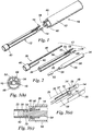
Figure 1 is a general view of an embodiment of autoinjection device, showing the reuseable drive assembly and the disposable syringe assembly prior to coupling; -
Figure 2 is a general view of the components making up the syringe assembly; -
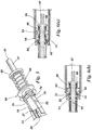
Figures 3(a) to (c) are detailed views showing the coupling engagement between the syringe assembly and the drive assembly; -
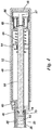
Figure 4 is a longitudinal cross-section view through the drive assembly, with the safety catch locked; -
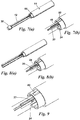
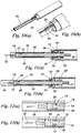
Figure 5 is a detailed view on the mechanism associated with the plunger for releasing the syringe assembly from the drive assembly at the end of the forward stroke of movement of the plunger; -
Figures 6(a) and (b) are longitudinal section views through a forward part of the drive assembly showing operation of the release mechanism; -
Figures 7(a) and (b) are a view of the syringe assembly coupled to the drive assembly prior to removal of the boot remover, and a detailed view on the syringe latch respectively; -
Figures 8(a) and (b) are views similar toFigures 5(a) and (b) but after removal of the boot remover; -
Figure 9 is a detailed view on the syringe latch showing resilient flexing thereof to release the shield latch pip on the syringe; -
Figures 10(a) and (b) are views similar toFigures 6(a) and (b) but following release of the plunger to drive the syringe forwardly to expose its needle; -
Figures 11 (a) and (b) are longitudinal section views through the syringe assembly showing the release mechanism that re-extends the shield over the syringe to shield the needle on completion of the injection and release of the syringe assembly, and -
Figures 12(a) and (b) are longitudinal sections through the forward end of the syringe assembly showing operation of the one way gripper arrangement between the syringe plunger and thesyringe body 20. - Referring initially to
Figure 1 , the illustrated embodiment of autoinjection device comprises adrive assembly 10 releasably coupled to asyringe assembly 12 by a pair ofcoupling tongues 14 on the syringe assembly designed to snap fit intolocking recesses 16 on the drive assembly, as to be described below in relation toFigures 3 (a) to (c) . The drive assembly is designed to be reusable whereas the syringe assembly is a single use disposable item. In order to reduce the environmental impact, the syringe assembly is made of just three components as illustrated inFigure 2 , all of which, with the exception of the syringe needle, are moulded from recyclable plastics material. - As seen in
Figure 2 , the syringe assembly comprises a mouldedplastic syringe 18 having acylindrical body 20 from the forward end of which extends aneedle 22 and provided at its rear end with a radially projectingshield latch pip 24. Theneedle shield 26 is of open ended shell form with thecoupling tongues 14 extending rearwardly therefrom. Thecoupling tongues 14 havecoupling ramps 28 which effect a snap fit coupling as to be described below and are capable of resilient flexing movement. At the rear end of the needle shield 26 (and viewable on enlarged scale inFigure 3(a) ) is acontrol slot 30 designed slideably to receive theshield latch pip 24. At its rear end, thecontrol slot 30 has a latch recess 32 in which theshield latch pip 24 can be releasably latched. Alocking slot 34 runs in akeyway 36 extending along the length of theneedle shield 26 with thekeyway 36 being cut away at its rear end to leave aresilient finger 37 defining one edge of theslot 30 and allowing resilient flexing to release thelatch recess 32 when thelocking slot 34 is empty. - A
boot remover 38 carries at its forward end acap 40 from the rear of which extends a cylindricalboot remover portion 42, having internal barbs or other suitable grip elements (not shown) to engage aboot 43 which covers theneedle 22 prior to use. Extending rearwardly from thecap 40 is a boot removerfinger 46 designed to be a slideable fit in theslot 34. When theboot remover 38 is fitted to the front end of the shield (as seen for example inFigures 1 and 3(a) ) the boot removerfinger 46 extends alongside theslot 30 to protrude rearwardly from the edge of theneedle shield 26 to lock a safety catch arrangement as to be described below. - Referring now to
Figures 3(a) to (c) , the syringe assembly is coupled to the drive assembly by offering up thetongues 14 to the locking recesses 16 and pushing the syringe assembly rearwardly to effect a snap fit. Themain body portion 48 of thedrive assembly 10 has atooth 50 extending rearwardly and inwardly from each lockingrecess 16 and designed so that when thecoupling tongues 14 pass through therecesses 16, theramps 28 snap fit behind theteeth 50 to lock thesyringe assembly 12 against forward movement. - Referring now to
Figure 4 , thedrive assembly 10 includes atrigger sleeve 52 slideably mounted around the outside of themain body 48. Aplunger 54 is slideably mounted within themain body 48 and urged forwardly by amain drive spring 56. The plunger has at its rear end a splitarrowhead locking latch 57 or similar which holds the plunger in a rearward position in the main body with the drive spring energised. Atrigger cap 58 is slideably mounted on the rear end of themain body 48 and movable forwardly from a rest position to squeeze together the split arrowhead to release the lockinglatch 57 and to release theplunger 54 for forward movement. At the forward end of themain body 48 there is aflexible safety catch 60 which, when in the 'safe' position shown inFigure 4 , prevents forward movement of thetrigger sleeve 52 to the firing position. Thesafety catch 60 is held in its 'safe' position inFigure 4 by the rearward end of the boot removerfinger 46. Upon forward withdrawal of theboot remover 46, this constraint is removed thereby unlocking the safety catch so that it can be cammed or pushed manually down as thetrigger sleeve 52 is moved to a forward position in which it moves thetrigger cap 58 to release the plunger. As evident fromFigure 4 , upon forward movement, theplunger 54 will engage at its forward end thesyringe bung 62. - Referring now more particularly to
Figures 5 and 6(a) and (b) , arelease collar 64 is slideably mounted towards the rear end of the plunger and biased forwardly by anejection spring 66 acting between aflange 68 integral with the plunger and the rear end of therelease collar 64. Therelease collar 64 has at its forward end opposed part-conical release surfaces 70 designed to urge thecoupling tongues 14 inwards to release the coupling ramps 28 to uncouple thesyringe assembly 12 from thedrive assembly 10 at the end of an injection. As seen inFigure 6(a) , as the plunger approaches its forwardmost position, therelease collar 64 squeezes thecoupling tongues 14 inwards and then pushes theshield 26 forwardly relative to the drive assembly as seen inFigure 6(b) . - In use, the drive assembly is loaded if necessary by pushing the
plunger 54 back into the main body so that the plunger is latched in its rearward position and the trigger sleeve is locked in a rearward position by thesafety catch 60. Afresh syringe assembly 12 with itsboot remover 38 closing the forward end and with the syringe latched in its rearward position relative to theshield 26 is offered up to thedrive assembly 10 and snap fitted into position with thetongues 14 locked into the locking recesses 16. In this configuration, theboot remover 38 fulfils several different functions. It closes off the front end of the shield; the lockingfinger 46 prevents resilient flexing movement of theresilient finger 36 and thus prevents unlatching and forward movement of the syringe relative to the shield; the lockingfinger 46 also prevents release of thesafety catch 60, as seen inFigures 7(a) and (b) . - Removal of the boot remover removes the
boot 43 from thesyringe needle 22 and unlocks theresilient finger 37 of thelatch 22 so that the syringe is ready for forward movement. Finally, thesafety catch 60 is unlocked. The assembled autoinjector is then offered up to the injection site with the front end of the shield placed against the skin. Thesafety catch 60 is released and thetrigger sleeve 52 moved forwardly to release the plunger. Upon initial release of the plunger, it acts via thepiston bung 62 and the liquid charge in the syringe which acts initially as a solid to move thesyringe 18 bodily forward so that theshield latch pip 24 springs out of thelatch recess 32 and moves down thecontrol slot 30 to the position shown inFigures 10(a) and (b) with itsneedle 22 extended. The syringe is then prevented from further movement by the pip reaching the forward end of the slot and so the plunger now moves the bung 62 forwardly to express the dose. - As shown in
Figure 11 , as theplunger 54 reaches its forward end, therelease collar 64 squeezes the ends of thecoupling tongues 14 together to uncouple theshield 26 from the main body of the drive assembly. At this point theshield 26 does not yet move forwardly relative to the syringe because the injection device is still pressing against the skin. On release of that pressure, theneedle shield 26 moves forwardly under the influence of theejection spring 66 until theshield latch pip 24 snaps back into the latch recess 33. - During this movement, it is important that the syringe does not move forwardly with the shield. For this purpose, as shown in
Figures 12(a) and (b) there is a one-way clutch arrangement provided between the plunger and thesyringe body 20. The plunger has anannular groove 70 with a ramped or frustoconical base 72, which receives a 'O'ring 74. When the plunger is moving towards or into the syringe the 'O'ring 74 is urged towards the deeper part of thegroove 70 thus providing little or no resistance to movement, as shown inFigure 12(a) . However, movement of the plunger in the opposite sense drives the 'O' ring into engagement with thesyringe body 20 thus tending to resist rearward movement, as shown inFigure 12(b) . The resistance to rearward movement of the plunger is designed to be sufficient to hold the syringe against forward movement to ensure proper extension and latching of the needle shield, but to be overcome when it is required to slide the uncoupled syringe assembly off the extended plunger. - The
boot remover 38 is reapplied to the shield with the lockingfinger 46 sliding along theslot 34 to block resilient movement of theresilient finger 36. Thesyringe assembly 10 is now safe for disposal. Apart from the needle which will typically be of metal material, the remainder of the syringe assembly may be made principally or wholly of recyclable plastics material such as thermoplastic material. - Embodiments of the invention may include features selected from any combination of the following list of features:
- 1. A syringe assembly (12) comprising:
- a syringe (18) having a body (20) and a needle (22), and
- a shield (26) slideably mounted around said syringe for telescopic movement between a retracted position in which the syringe needle (22) is exposed in use and an extended position in which the needle is at least partially shrouded by said shield,
- wherein said syringe body (20) has a feature (24) thereon which cooperates with an associated feature (30) on the shield to control relative movement thereof.
- 2. A syringe assembly, wherein said syringe body (20) and said feature (24) are of moulded plastics material.
- 3. A syringe assembly, wherein said cooperating features (24, 30) limit the extent of telescopic movement of the syringe (18) and the shield (26).
- 4. A syringe assembly, wherein said cooperating features (24, 30) are operable releasably to latch said shield (26) in a forward position relative to the syringe (18).
- 5. A syringe assembly wherein said cooperating features comprise a projection (24) on one of the syringe (18) or shield (26), cooperating with a control slot on the other thereof.
- 6. A syringe assembly wherein said
projection 24 is on saidsyringe body 20. - 7. A syringe assembly wherein said slot (30) is provided at one end region with a latch recess (32) for releasably retaining said projection (44), and the wall of the slot (37), at least in the region of said latch recess, is resiliently deformable to allow said projection (24) to snap out of said recess (32) to allow said shield to move rearwardly relative to the syringe.
- 8. A syringe assembly further including a locking member (40) engageable adjacent or near said slot (30) for inhibiting resilient movement of said latch recess to prevent release of said projection (24).
- 9. A syringe assembly wherein said locking member (46) is engageable by being longitudinally slideable into a locking slot (34) provided alongside said control slot (30).
- 10. A syringe assembly wherein said locking member (46) carries at its forward end a cap (46) for closing the forward end of said shield (26), when applied to the forward end of said shield, and with the locking member slid longitudinally into said locking slot.
- 11. A syringe assembly wherein said syringe includes a boot (43) covering said needle (22) prior to use, and said cap (40) includes means (42) for engaging said boot when said cap is applied to said shield, such that removal of said cap removes said boot.
- 12. A syringe assembly wherein said syringe assembly (12) is adapted to be releasably coupled in use to the drive assembly (10) of an autoinjection device, the drive assembly including a drive (56) for expelling a dose from the syringe, a trigger for releasing said drive, and a safety arrangement for preventing inadvertent actuation of said drive (52, 58), wherein said locking member (46) releases said safety arrangement (60) and/or unlocks said safety arrangement for subsequent release, when said locking member is removed from said shield.
- 13. A syringe assembly wherein the syringe (18) is carried inside said shield (26) by direct sliding engagement therebetween.
- 14. A syringe assembly wherein said syringe assembly (12) is adapted to be releasably coupled in use to the drive assembly (10) of an autoinjector device, the drive assembly (10) including a drive (56) adapted in use to express a dose from the syringe, wherein said syringe assembly (12) is coupled to said drive assembly (10) in use by interengagement of a portion of said shield (26) with said drive assembly.
- 15. A syringe assembly wherein said shield (26) includes one or more features for snap engagement in use with an associated one or more features on said drive assembly (10).
- 16. A syringe assembly wherein, in use, said drive is adapted to uncouple said shield from said drive assembly on approaching or reaching the forwardmost extent of movement.
- 17. An autoinjection device comprising a removable syringe assembly.
- 18. An autoinjection device comprising:
- a syringe (18) having a needle which prior to injection carries a boot (43);
- a shield (26) movable relative to said syringe between an extended position in which the needle is at least partially shrouded and a retracted position in which the needle is exposed;
- a drive assembly (10) for expelling a dose from the syringe;
- a trigger (52, 58) for actuating said drive assembly;
- a safety arrangement (60) for preventing inadvertent actuation of said drive assembly, and
- a boot remover (38) applied to the forward end of said autoinjector and adapted to engage said boot (43), said boot remover being arranged to prevent movement of said syringe (18) relative to said shield (26) in at least one direction, and to prevent release of said safety arrangement (60) until said boot remover is removed from the front end of the device.
- 19. An autoinjection device comprising:
- a drive assembly (10) and a syringe assembly (12) adapted to be coupled and uncoupled in use, the syringe assembly including a shield (26) and a syringe (18) movable with respect to said shield and having a needle (22), the drive assembly including a drive (56) and a trigger (52, 58) for actuating said drive to drive a plunger (54) forwardly to move the syringe (18) forwardly relative to the shield (26) and to expel a dose from the syringe, characterised in that the syringe assembly (12) is coupled to said drive assembly (10) by one or more engagement elements (14) on said shield engaging one or more cooperating elements (50) on said drive assembly, and in that said plunger disengages said features as it approaches or reaches its forward position, to release the syringe assembly (12).
- 20. An autoinjection device, wherein said plunger (54) includes a pressure member (64) slideably mounted thereon and biased (66) forwardly, and said pressure member disengages said elements (14) and applies a forward bias to said shield (26) to cause it to move forwardly relative to the syringe to at least partially shroud the needle when the autoinjection device is removed from the skin following injection.
- 21. An autoinjection device, wherein said syringe (18) and said shield (26) include complementary latch features (24, 32) adapted releasably to latch the syringe in a rearward shrouded position relative to the shield before and after use.
- 22. An autoinjection device wherein, upon actuation of said drive, said plunger (54) acts on a bung (62) in the syringe (18) to drive the syringe forwardly, thereby unlatching it from the shield (26).
- 23. An autoinjection device, wherein upon removal of said autoinjection device from the skin after an injection, the forwardly biased pressure member (64), having disengaged the shield (26) from the drive assembly (10) moves the shield (26) forward relative to the syringe (18) until the latch (32) between the syringe and the shield re-engages.
- 24. An autoinjection device, including an arrangement (70, 74) to resist forward movement of the syringe relative to the plunger as the pressure plate moves the shield forwardly upon completion of an injection.
- 25. An autoinjection device, wherein the arrangement to resist forward movement comprises a one way clutch arrangement between the plunger (54) and the syringe (18) which imparts little or no resistance to forward (closing) movement of the plunger relative to the syringe but applies a greater resistance to rearward (separating) movement of the plunger relative to the syringe.
- 26. An autoinjection device, wherein said plunger (54) extends inside the bore of the syringe and carries a gripper element (74) that is engageable with the inner wall of the syringe bore, and arranged such that the gripper element is forced into engagement with, or into tighter engagement with, said inner wall rearward (separating) movement of said plunger.
- 27. An autoinjection device, wherein said plunger has a recess (72) with a ramp surface that urges the gripper element (74) into engagement with the inner wall surface of the syringe.
- 28. An autoinjection device, wherein said plunger has an annular groove (70) with a frustro-conical base providing said ramp, and said gripper element comprises an 'O' ring (74).
- 29. An injection device comprising:
- a syringe (18) having a body (20) and a plunger (54) having a portion extending within the body of said syringe and adapted to expel a dose, including means (72, 74) to impart significantly greater resistance to separating movement of the plunger and the syringe, than in the opposite direction.
- 30. An injection device, wherein the arrangement to resist movement comprises a one way clutch arrangement between the plunger and syringe, which imparts little or no resistance to forward (closing) movement of the plunger relative to the syringe, but applies a greater resistance to rearward (separating) movement of the plunger relative to the syringe.
- 31. An injection device, wherein said plunger (54) extends inside the bore of the syringe and carries a gripper element (74) that is engageable with the inner wall of the syringe, and the arrangement being such that the gripper element is forced into engagement with, or into tighter engagement with said inner wall on rearward (separating) movement of said plunger.
- 32. An injection device, wherein said plunger has a recess (70) with a ramp surface (72) that urges the gripper element (74) into engagement with said inner wall surface.
- 33. An injection device, wherein said plunger has an annular groove (70) with a frustro-conical base (72) providing said ramp, and said gripper element is an 'O' ring (74).
- 34. An injection device, wherein the plunger (54) cooperates with a piston (62) slideably mounted within said syringe.
- 35. An autoinjection device comprising:
- a reusable drive assembly (10) releasably coupled to a disposable syringe assembly (12), the syringe assembly comprising a shield (26) and a syringe (18), the syringe having a needle (22), the syringe being telescopically movable within said shield, between a retracted position in which the need is at least partially shielded, and an extended position in which the needle is exposed, the drive assembly (10) comprising a drive (56) and a trigger (52, 58) for actuating said drive arrangement to expel a dose from the syringe, characterised in that the syringe assembly is releasably coupled to the drive assembly by engagement of a coupling portion (14) on the shield with a coupling portion (50) in the drive assembly (10).
- 36. An autoinjection device, wherein drive assembly includes a plunger (54), which is moved forwards to extend said syringe and to expel a dose upon actuation of said trigger, said plunger (54) being adapted to release said coupling portions (14, 50) upon approaching or reaching a forward position.
Claims (12)
- An autoinjection device comprising:a reusable drive assembly (10) releasably coupled to a disposable syringe assembly (12), the syringe assembly comprising a shield (26) and a syringe (18), the syringe having a needle (22), the syringe being telescopically movable within said shield, between a retracted position in which the need is at least partially shielded, and an extended position in which the needle is exposed, the drive assembly (10) comprising a drive (56) and a trigger (52, 58) for actuating said drive arrangement to expel a dose from the syringe, characterised in that the syringe assembly is releasably coupled to the drive assembly by engagement of a coupling portion (14) on the shield with a coupling portion (50) in the drive assembly (10).
- An autoinjection device according to Claim 1, wherein drive assembly includes a plunger (54), which is moved forwards to extend said syringe and to expel a dose upon actuation of said trigger, said plunger (54) being adapted to release said coupling portions (14, 50) upon approaching or reaching a forward position.
- An autoinjection device according to Claim 2, wherein said plunger (54) includes a pressure member (64) slideably mounted thereon and biased (66) forwardly, and said pressure member disengages said coupling portions (14) and applies a forward bias to said shield (26) to cause it to move forwardly relative to the syringe to at least partially shroud the needle when the autoinjection device is removed from the skin following injection.
- An autoinjection device according to any preceding claim, wherein said syringe (18) and said shield (26) include complementary latch features (24, 32) adapted releasably to latch the syringe in a rearward shrouded position relative to the shield before and after use.
- An autoinjection device according to Claim 4, wherein upon actuation of said drive, said plunger (54) acts on a bung (62) in the syringe (18) to drive the syringe forwardly, thereby unlatching it from the shield (26).
- An autoinjection device according to Claim 5, wherein upon removal of said autoinjection device from the skin after an injection, the forwardly biased pressure member (64), having disengaged the shield (26) from the drive assembly (10) moves the shield (26) forward relative to the syringe (18) until the latch (32) between the syringe and the shield re-engages.
- An autoinjection device according to Claim 6, including an arrangement (70, 74) to resist forward movement of the syringe relative to the plunger as the pressure plate moves the shield forwardly upon completion of an injection.
- An autoinjection device according to any preceding claim, wherein the syringe assembly (12) has a body (20) and the syringe body has a feature (24) thereon which cooperates with an associated feature (30) on the shield to control relative movement thereof.
- An autoinjection device according to Claim 8, wherein said syringe body (20) and said feature (24) are of moulded plastics material.
- An autoinjection device according to Claim 8 or Claim 9, wherein said cooperating features (24, 30) limit the extent of telescopic movement of the syringe (18) and the shield (26).
- An autoinjection device according to any of Claims 8 to 10, wherein said cooperating features (24, 30) are operable releasably to latch said shield (26) in a forward position relative to the syringe (18).
- An autoinjection device according to any preceding claim, wherein the syringe has a needle which prior to injection carries a boot (43), and wherein the device includes
a trigger (52, 58) for actuating said drive assembly;
a safety arrangement (60) for preventing inadvertent actuation of said drive assembly, and
a boot remover (38) applied to the forward end of said autoinjector and adapted to engage said boot (43), said boot remover being arranged to prevent movement of said syringe (18) relative to said shield (26) in at least one direction, and to prevent release of said safety arrangement (60) until said boot remover is removed from the front end of the device.
Applications Claiming Priority (4)
| Application Number | Priority Date | Filing Date | Title |
|---|---|---|---|
| US17464209P | 2009-05-01 | 2009-05-01 | |
| GBGB0907534.2A GB0907534D0 (en) | 2009-05-01 | 2009-05-01 | Injection devices |
| EP15157452.2A EP2907537B1 (en) | 2009-05-01 | 2010-04-30 | Injection devices |
| EP10720661.7A EP2429614B1 (en) | 2009-05-01 | 2010-04-30 | Injection devices |
Related Parent Applications (2)
| Application Number | Title | Priority Date | Filing Date |
|---|---|---|---|
| EP15157452.2A Division EP2907537B1 (en) | 2009-05-01 | 2010-04-30 | Injection devices |
| EP10720661.7A Division EP2429614B1 (en) | 2009-05-01 | 2010-04-30 | Injection devices |
Publications (1)
| Publication Number | Publication Date |
|---|---|
| EP3266479A1 true EP3266479A1 (en) | 2018-01-10 |
Family
ID=40792117
Family Applications (3)
| Application Number | Title | Priority Date | Filing Date |
|---|---|---|---|
| EP10720661.7A Not-in-force EP2429614B1 (en) | 2009-05-01 | 2010-04-30 | Injection devices |
| EP17185922.6A Withdrawn EP3266479A1 (en) | 2009-05-01 | 2010-04-30 | Injection device |
| EP15157452.2A Active EP2907537B1 (en) | 2009-05-01 | 2010-04-30 | Injection devices |
Family Applications Before (1)
| Application Number | Title | Priority Date | Filing Date |
|---|---|---|---|
| EP10720661.7A Not-in-force EP2429614B1 (en) | 2009-05-01 | 2010-04-30 | Injection devices |
Family Applications After (1)
| Application Number | Title | Priority Date | Filing Date |
|---|---|---|---|
| EP15157452.2A Active EP2907537B1 (en) | 2009-05-01 | 2010-04-30 | Injection devices |
Country Status (6)
| Country | Link |
|---|---|
| US (1) | US9302054B2 (en) |
| EP (3) | EP2429614B1 (en) |
| JP (2) | JP5710594B2 (en) |
| CN (2) | CN104353158B (en) |
| GB (1) | GB0907534D0 (en) |
| WO (1) | WO2010125400A2 (en) |
Families Citing this family (54)
| Publication number | Priority date | Publication date | Assignee | Title |
|---|---|---|---|---|
| ES2314182T3 (en) | 2002-02-11 | 2009-03-16 | Antares Pharma, Inc. | INTRADERMIC INJECTOR. |
| FR2852851B1 (en) * | 2003-03-25 | 2006-01-06 | Sedat | NEEDLE PROTECTION DEVICE FOR SYRINGE, AND INJECTION DEVICE COMPRISING SYRINGE AND PROTECTIVE DEVICE |
| IL157981A (en) | 2003-09-17 | 2014-01-30 | Elcam Medical Agricultural Cooperative Ass Ltd | Auto-injector |
| FR2861310B1 (en) | 2003-10-22 | 2006-09-22 | Plastef Investissements | SECURE INJECTION SYRINGE DEVICE |
| EP1850892B2 (en) | 2005-01-24 | 2023-04-19 | Antares Pharma, Inc. | Prefilled needle assisted syringe jet injector |
| WO2007131013A1 (en) | 2006-05-03 | 2007-11-15 | Antares Pharma, Inc. | Two-stage reconstituting injector |
| US9144648B2 (en) | 2006-05-03 | 2015-09-29 | Antares Pharma, Inc. | Injector with adjustable dosing |
| FR2922455B1 (en) | 2007-10-23 | 2010-10-29 | Plastef Investissements | SYRINGE DEVICE COMPRISING A SYRINGE BODY AND A SUPPORT SLEEVE. |
| WO2009114542A1 (en) | 2008-03-10 | 2009-09-17 | Antares Pharma, Inc. | Injector safety device |
| EP2318075B1 (en) | 2008-08-05 | 2019-05-22 | Antares Pharma, Inc. | Multiple dosage injector |
| EP2408493A1 (en) | 2009-03-20 | 2012-01-25 | Antares Pharma, Inc. | Hazardous agent injection system |
| EP2488237B1 (en) | 2009-10-16 | 2018-07-04 | Janssen Biotech, Inc. | Palm activated drug delivery device |
| US9233213B2 (en) | 2009-10-16 | 2016-01-12 | Janssen Biotech, Inc. | Palm activated drug delivery device |
| EP2468339A1 (en) | 2010-12-21 | 2012-06-27 | Sanofi-Aventis Deutschland GmbH | Auto-injector |
| GB2486681B (en) * | 2010-12-22 | 2017-02-01 | Owen Mumford Ltd | Autoinjectors |
| WO2012103140A1 (en) * | 2011-01-24 | 2012-08-02 | Abbott Biotechnology Ltd | Removal of needle shields from syringes and automatic injection devices |
| US9022990B2 (en) | 2011-04-04 | 2015-05-05 | Tech Group Europe Limited | Needle safety shield |
| CA2832033C (en) * | 2011-04-05 | 2016-02-09 | Shl Group Ab | Medicament delivery device comprising a locking mechanism having a lever |
| US8496619B2 (en) | 2011-07-15 | 2013-07-30 | Antares Pharma, Inc. | Injection device with cammed ram assembly |
| US9220660B2 (en) | 2011-07-15 | 2015-12-29 | Antares Pharma, Inc. | Liquid-transfer adapter beveled spike |
| PT2822618T (en) | 2012-03-06 | 2024-03-04 | Antares Pharma Inc | Prefilled syringe with breakaway force feature |
| JP6457383B2 (en) | 2012-04-06 | 2019-01-23 | アンタレス・ファーマ・インコーポレーテッド | Needle-assisted jet injection of testosterone composition |
| WO2013169804A1 (en) | 2012-05-07 | 2013-11-14 | Antares Pharma, Inc. | Needle assisted jet injection device having reduced trigger force |
| US9050416B2 (en) | 2012-11-01 | 2015-06-09 | Tech Group Europe Limited | Needle Safety device with floating ring |
| US9636462B2 (en) | 2012-11-02 | 2017-05-02 | Novo Nordisk A/S | Drug delivery device with shield operated needle actuator |
| ES2763633T3 (en) | 2013-02-11 | 2020-05-29 | Antares Pharma Inc | Needle assisted jet injection device having reduced firing force |
| GB2511317A (en) | 2013-02-27 | 2014-09-03 | Owen Mumford Ltd | Automatic injection device |
| ES2742046T3 (en) | 2013-03-11 | 2020-02-12 | Antares Pharma Inc | Dose injector with pinion system |
| WO2014165136A1 (en) | 2013-03-12 | 2014-10-09 | Antares Pharma, Inc. | Constant volume prefilled syringes and kits thereof |
| EP2978472B1 (en) * | 2013-03-25 | 2019-02-06 | SHL Medical AG | Power pack lock |
| EP2886146A1 (en) * | 2013-12-20 | 2015-06-24 | Sanofi-Aventis Deutschland GmbH | Needle safety device and drug delivery device |
| US10751470B2 (en) | 2014-02-10 | 2020-08-25 | E3D A.C.A.L Ltd | Semi disposable auto injector |
| NO2689315T3 (en) | 2014-10-28 | 2018-04-14 | ||
| US9199033B1 (en) | 2014-10-28 | 2015-12-01 | Bayer Healthcare Llc | Self-orienting syringe and syringe interface |
| EP3212256A4 (en) | 2014-10-28 | 2018-07-18 | Bayer HealthCare LLC | Self-orienting pressure jacket and pressure jacket-to-injector interface |
| BR112017008878B1 (en) | 2014-10-28 | 2022-10-11 | Bayer Healthcare Llc | PRESSURE SHIRT |
| CN107206180A (en) * | 2015-01-16 | 2017-09-26 | 赛诺菲-安万特德国有限公司 | Medicament delivery device |
| GB2541227A (en) * | 2015-08-13 | 2017-02-15 | Owen Mumford Ltd | Injector Device |
| ES2866078T3 (en) | 2015-08-27 | 2021-10-19 | E3D Agricultural Coop Association Ltd | Reusable automatic injection device |
| CN108472433B (en) | 2015-11-13 | 2021-12-14 | 拜耳医药保健有限公司 | Nested syringe assembly |
| GB201600988D0 (en) | 2016-01-19 | 2016-03-02 | Owen Mumford Ltd | Auto-injector apparatus |
| EP3202448A1 (en) * | 2016-02-08 | 2017-08-09 | F. Hoffmann-La Roche AG | Device and method for safe and easy removal of a needle shield element from a pharmaceutical syringe |
| EP4137182A1 (en) * | 2016-02-24 | 2023-02-22 | SHL Medical AG | Safety mechanism for a medicament delivery device and a medicament delivery device comprising the same |
| JP6596165B2 (en) * | 2016-02-24 | 2019-10-23 | エス・ハー・エル・メディカル・アクチェンゲゼルシャフト | Safety mechanism of drug delivery device and drug delivery device having the same |
| US20180015224A1 (en) | 2016-07-13 | 2018-01-18 | California Institute Of Technology | Dampers and Methods for Performing Measurements in an Autoinjector |
| WO2018111616A1 (en) | 2016-12-16 | 2018-06-21 | Kimberly-Clark Worldwide, Inc. | Application device for a fluid delivery apparatus and method of use |
| CA3046799A1 (en) | 2016-12-16 | 2018-06-21 | Sorrento Therapeutics, Inc. | Fluid delivery apparatus and method of assembly |
| US11191893B2 (en) | 2018-01-31 | 2021-12-07 | Bayer Healthcare Llc | System and method for syringe engagement with injector |
| WO2019158372A1 (en) * | 2018-02-19 | 2019-08-22 | Shl Medical Ag | A medicament delivery device with an easily connected disposable and reusable units |
| WO2019202128A1 (en) * | 2018-04-19 | 2019-10-24 | Sanofi | Force reduction in injection devices |
| EP3941552A1 (en) * | 2019-03-22 | 2022-01-26 | Phillips-Medisize A/S | Auto injector with bi-stable clutch plate |
| AU2019466785A1 (en) * | 2019-09-19 | 2022-03-31 | Cc Biotechnology Corporation | Common injection device |
| CN213554490U (en) * | 2020-09-18 | 2021-06-29 | 山东威高普瑞医药包装有限公司 | Safety device for a prefilled syringe and injection device |
| EP4108277A1 (en) * | 2022-07-22 | 2022-12-28 | Ypsomed AG | Syringe unit for a reusable injection device |
Citations (2)
| Publication number | Priority date | Publication date | Assignee | Title |
|---|---|---|---|---|
| EP0824923A1 (en) * | 1996-08-23 | 1998-02-25 | Becton Dickinson France S.A. | Cartrigde with temporarily lockable cap for an injection device |
| US7500963B2 (en) * | 2003-07-22 | 2009-03-10 | Safety Syringes, Inc. | Systems and methods for automatic medical injection with safeguard |
Family Cites Families (28)
| Publication number | Priority date | Publication date | Assignee | Title |
|---|---|---|---|---|
| US2895474A (en) * | 1955-01-04 | 1959-07-21 | Cook Waite Lab Inc | Aspirating cartridge syringe |
| FR2342079A1 (en) | 1976-02-25 | 1977-09-23 | Constantinidis Alexandre | Automatic intramuscular syringe - with preloaded springs for needle entry injection and retraction |
| IN169618B (en) * | 1987-06-25 | 1991-11-23 | Agven Medical Corp Ltd | |
| US5059185A (en) * | 1988-03-01 | 1991-10-22 | Ryan Medical, Inc. | Safety needled medical devices |
| US5030209A (en) * | 1988-11-09 | 1991-07-09 | Medical Safety Products, Inc. | Holder for double ended blood collection retractable needle |
| US5088985A (en) * | 1990-08-01 | 1992-02-18 | Deras Marco A | Safety syringe |
| GB9200219D0 (en) * | 1992-01-07 | 1992-02-26 | Medimech Int Ltd | Automatic injectors |
| US5370620A (en) * | 1992-12-28 | 1994-12-06 | Shonfeld; David | Single use hypodermic syringe |
| US5620421A (en) | 1993-12-09 | 1997-04-15 | Schmitz; William L. | Syringe injector system |
| JP3211223B2 (en) | 1994-12-28 | 2001-09-25 | ニプロ株式会社 | Prefilled syringe |
| FR2749764B1 (en) * | 1996-06-13 | 1999-12-31 | Moreau Defarges Alain | IMPROVED SAFETY DEVICE FOR NEEDLE-FREE JET INJECTION |
| US5709662A (en) * | 1996-08-23 | 1998-01-20 | Becton Dickinson France, S.A. | Cartridge for an injection device |
| SE9803662D0 (en) * | 1998-10-26 | 1998-10-26 | Pharmacia & Upjohn Ab | autoinjector |
| FR2799375B1 (en) * | 1999-10-07 | 2002-01-18 | Marc Brunel | SINGLE USE INJECTION DEVICE |
| GB0007071D0 (en) * | 2000-03-24 | 2000-05-17 | Sams Bernard | One-way clutch mechanisms and injector devices |
| US6613022B1 (en) * | 2000-05-05 | 2003-09-02 | Safety Syringes, Inc. | Passive needle guard for syringes |
| JP2003220142A (en) * | 2002-01-30 | 2003-08-05 | Yoshino Kogyosho Co Ltd | Syringe |
| US20050027255A1 (en) | 2003-07-31 | 2005-02-03 | Sid Technologies, Llc | Automatic injector |
| IL157981A (en) * | 2003-09-17 | 2014-01-30 | Elcam Medical Agricultural Cooperative Ass Ltd | Auto-injector |
| US7449012B2 (en) * | 2004-08-06 | 2008-11-11 | Meridian Medical Technologies, Inc. | Automatic injector |
| DE102004063644A1 (en) * | 2004-12-31 | 2006-07-20 | Tecpharma Licensing Ag | Device for the dosed administration of a fluid product with torsion spring drive |
| GB2434103B (en) * | 2006-01-12 | 2009-11-25 | Owen Mumford Ltd | Lancet firing device |
| GB2438590B (en) * | 2006-06-01 | 2011-02-09 | Cilag Gmbh Int | Injection device |
| DK1932558T3 (en) * | 2006-12-13 | 2011-09-05 | Shl Group Ab | autoinjector |
| US8460250B2 (en) | 2007-06-26 | 2013-06-11 | Terumo Kabushiki Kaisha | Medical container |
| CN101912648B (en) * | 2008-01-23 | 2013-04-24 | 诺沃-诺迪斯克有限公司 | Device for injecting apportioned doses of liquid drug |
| CN103041478B (en) | 2008-04-10 | 2015-01-21 | 松下健康医疗控股株式会社 | Medication administering device |
| GB2463071A (en) | 2008-09-02 | 2010-03-03 | Owen Mumford Ltd | Auto-injector syringe with safety shield |
-
2009
- 2009-05-01 GB GBGB0907534.2A patent/GB0907534D0/en not_active Ceased
-
2010
- 2010-04-30 WO PCT/GB2010/050723 patent/WO2010125400A2/en active Application Filing
- 2010-04-30 EP EP10720661.7A patent/EP2429614B1/en not_active Not-in-force
- 2010-04-30 US US13/318,392 patent/US9302054B2/en active Active
- 2010-04-30 CN CN201410545028.3A patent/CN104353158B/en active Active
- 2010-04-30 JP JP2012507825A patent/JP5710594B2/en not_active Expired - Fee Related
- 2010-04-30 EP EP17185922.6A patent/EP3266479A1/en not_active Withdrawn
- 2010-04-30 CN CN201080019102.8A patent/CN102427841B/en not_active Expired - Fee Related
- 2010-04-30 EP EP15157452.2A patent/EP2907537B1/en active Active
-
2015
- 2015-03-03 JP JP2015041396A patent/JP6073396B2/en not_active Expired - Fee Related
Patent Citations (2)
| Publication number | Priority date | Publication date | Assignee | Title |
|---|---|---|---|---|
| EP0824923A1 (en) * | 1996-08-23 | 1998-02-25 | Becton Dickinson France S.A. | Cartrigde with temporarily lockable cap for an injection device |
| US7500963B2 (en) * | 2003-07-22 | 2009-03-10 | Safety Syringes, Inc. | Systems and methods for automatic medical injection with safeguard |
Also Published As
| Publication number | Publication date |
|---|---|
| JP6073396B2 (en) | 2017-02-01 |
| JP5710594B2 (en) | 2015-04-30 |
| US20120095408A1 (en) | 2012-04-19 |
| CN102427841B (en) | 2014-11-12 |
| EP2907537B1 (en) | 2017-08-30 |
| WO2010125400A2 (en) | 2010-11-04 |
| US9302054B2 (en) | 2016-04-05 |
| EP2429614A2 (en) | 2012-03-21 |
| EP2907537A1 (en) | 2015-08-19 |
| CN104353158B (en) | 2017-07-18 |
| CN102427841A (en) | 2012-04-25 |
| WO2010125400A3 (en) | 2011-01-20 |
| GB0907534D0 (en) | 2009-06-10 |
| CN104353158A (en) | 2015-02-18 |
| EP2429614B1 (en) | 2015-04-08 |
| JP2012525185A (en) | 2012-10-22 |
| JP2015097911A (en) | 2015-05-28 |
Similar Documents
| Publication | Publication Date | Title |
|---|---|---|
| EP2907537B1 (en) | Injection devices | |
| EP2331175B1 (en) | Syringe safety shields and autoinjector | |
| US8308695B2 (en) | Automatic injection device with actively triggered syringe withdrawal | |
| EP2782620B1 (en) | Autoinjector | |
| US11376364B2 (en) | Injection apparatus | |
| EP3377153B1 (en) | Needle shield mechanism and a medicament delivery device comprising the needle shield mechanism | |
| EP1362609A1 (en) | Disposable safety syringe with automatically guided outer sleeve | |
| US11318256B2 (en) | Injection device | |
| US20220370720A1 (en) | Injection Device | |
| EP2229968A1 (en) | Injection device having uncoupling means | |
| EP3442621A1 (en) | Injection device | |
| NZ531615A (en) | One-use retracting syringe with positive needle retention |
Legal Events
| Date | Code | Title | Description |
|---|---|---|---|
| PUAI | Public reference made under article 153(3) epc to a published international application that has entered the european phase |
Free format text: ORIGINAL CODE: 0009012 |
|
| STAA | Information on the status of an ep patent application or granted ep patent |
Free format text: STATUS: THE APPLICATION HAS BEEN PUBLISHED |
|
| AC | Divisional application: reference to earlier application |
Ref document number: 2429614 Country of ref document: EP Kind code of ref document: P Ref document number: 2907537 Country of ref document: EP Kind code of ref document: P |
|
| AK | Designated contracting states |
Kind code of ref document: A1 Designated state(s): AT BE BG CH CY CZ DE DK EE ES FI FR GB GR HR HU IE IS IT LI LT LU LV MC MK MT NL NO PL PT RO SE SI SK SM TR |
|
| STAA | Information on the status of an ep patent application or granted ep patent |
Free format text: STATUS: THE APPLICATION IS DEEMED TO BE WITHDRAWN |
|
| 18D | Application deemed to be withdrawn |
Effective date: 20180711 |