EP3266355B1 - Halteklammer für einen behälter - Google Patents
Halteklammer für einen behälter Download PDFInfo
- Publication number
- EP3266355B1 EP3266355B1 EP17179044.7A EP17179044A EP3266355B1 EP 3266355 B1 EP3266355 B1 EP 3266355B1 EP 17179044 A EP17179044 A EP 17179044A EP 3266355 B1 EP3266355 B1 EP 3266355B1
- Authority
- EP
- European Patent Office
- Prior art keywords
- container
- retaining clip
- retaining
- socket
- connecting portion
- Prior art date
- Legal status (The legal status is an assumption and is not a legal conclusion. Google has not performed a legal analysis and makes no representation as to the accuracy of the status listed.)
- Active
Links
Images

Classifications
-
- A—HUMAN NECESSITIES
- A47—FURNITURE; DOMESTIC ARTICLES OR APPLIANCES; COFFEE MILLS; SPICE MILLS; SUCTION CLEANERS IN GENERAL
- A47J—KITCHEN EQUIPMENT; COFFEE MILLS; SPICE MILLS; APPARATUS FOR MAKING BEVERAGES
- A47J45/00—Devices for fastening or gripping kitchen utensils or crockery
- A47J45/10—Devices for gripping or lifting hot cooking utensils, e.g. pincers, separate pot handles, fabric or like pads
Definitions
- the invention relates to a system comprising a container and a retaining clip, in particular for handling canned food that can be heated directly above a cooker.
- the invention has for its object to provide a system of a container and a retaining clip, which allows safe handling of the container. Based on the cited prior art, the object is achieved with the features of the independent claim. Advantageous embodiments are specified in the subclaims.
- the system according to the invention comprises a retaining clip with a socket, wherein an upper portion of the socket is adapted to an upper end of the container and a lower portion of the socket to a bottom of the container.
- a grip section has an upper leg and a lower leg, wherein the upper leg is connected via a first connecting portion with the upper portion of the socket and the lower leg via a second connecting portion with the lower portion of the socket.
- the socket can be put under tension by squeezing the legs.
- the retaining clip of the system according to the invention is designed so that a stable connection to the container can be made.
- the retaining clip By adapting the socket to the container, the retaining clip is in independent engagement with the container.
- no force is required by an operator to maintain the intervention.
- this procedure is usually not stable enough to lift and handle the container.
- By compressing the legs of the handle portion of the container is firmly clamped in the socket, so that a safe handling of the container is possible.
- the stability of the connection between retaining clip and container makes it possible not only to raise the container, but also to tilt, for example, to transfer a hot liquid from the container into a cup. If the retaining clip relaxed again, the engagement between the retaining clip and the container is maintained. Only by deliberate loosening the retaining clip is separated from the container.
- the socket By compressing the handle portion, the socket is stretched in the vertical direction, so that the upper portion of the socket rests with a higher force at the upper end of the container and that the lower portion of the socket rests with a higher force at the bottom of the container.
- the two legs of the handle portion may have a substantially horizontal orientation. The while the legs together applied force then acts essentially in the vertical direction.
- the directions refer to the retaining clip engaged with the upright container and are not intended to be limiting.
- the upper portion of the socket may have an upper extreme point.
- the upper extreme point is enclosed between an upper connecting portion extending from the extreme point to the upper leg of the grip portion, and an upper holding portion extending from the extreme point to an end face of the retaining clip.
- the upper connecting portion may include an angle between 10 ° and 40 °, preferably between 20 ° and 30 ° with the vertical.
- the upper holding portion may include an angle of at most 10 °, preferably at most 5 °, with the vertical.
- the upper holding portion is preferably free of a concave curvature. In this case, the curvature enclosed by the extreme point is referred to as convex. Thus, the upper holding portion continues the curvature enclosed by the extreme point without being curved again in the opposite direction.
- the lower portion of the socket may have a lower extreme point.
- the lower extreme point is enclosed between a lower connecting portion extending from the extreme point to the lower leg of the grip portion and a lower holding portion extending from the lower extreme point to an end face of the retaining clip.
- the angle which the lower connecting portion encloses with the vertical may be smaller than the angle which the upper connecting portion encloses with the vertical.
- the lower connecting portion an angle between 5 ° and 30 °, preferably between 10 ° and 20 ° with the vertical include.
- the lower holding portion may have a concave curvature, that is, a curvature that is opposite to the curvature enclosed by the extreme point.
- An arranged between the lower extreme point and the concave portion of the lower holding portion may include an angle between 60 ° and 90 °, preferably between 70 ° and 80 ° with the vertical.
- a portion of the lower support portion disposed between the concave portion and the end surface of the support bracket preferably includes an angle greater than 90 ° with the vertical.
- the angle can be between 90 ° and 110 °.
- the upper connecting portion may merge in a concave curvature in the upper leg of the handle portion.
- the lower connecting portion may merge in a concave curvature in the lower leg of the handle portion.
- the two legs of the handle portion may be interconnected by an end portion, wherein the transition between the legs and the end portion is formed by a convex curvature.
- the retaining clip may have rectilinear sections.
- the upper connecting portion may be between twice as long and five times as long as the upper holding portion.
- the lower connecting portion may be between twice as long and five times as long as the lower holding portion.
- the lower connecting portion may be between twice as long and five times as long as the upper connecting portion.
- the legs of the handle portion may be between twice as long and five times as long as the upper connecting portion.
- the lower connecting portion may be between twice as long and five times as long like the vertical distance between the two legs of the handle section.
- the legs of the retaining clip are aligned substantially parallel to one another.
- the opposite legs of the handle area is easy to grip and it can be applied uniformly pressure on both legs.
- the pressure is applied vertically from above and below on the legs. The danger of slippage when holding or tilting the container by means of the retaining clip of the legs, is significantly reduced.
- the retaining clip can be attached to a container, for example, during the attachment of the retaining clip to a container.
- the aligned in the direction of the lower portion of the socket portion act as a support surface for the container, which provides a fixed distance between the retaining clip and container before the retaining clip is completely engaged with the container.
- a force can be transmitted from the retaining clip in the portion directed towards the lower portion of the socket to the container holding the container in position.
- the concave curvature of the lower holding portion allows a particularly simple attachment of the retaining clip to a container, even if it rests firmly on a lower surface.
- this embodiment is advantageous because the hot container when attaching the retaining clip does not need to be held.
- the concave curvature of the lower holding portion can act as a kind of locking lug, which can engage in a recess at the bottom of the container.
- the handle portion and thus the retaining clip are easier to reach.
- the handle portion of the hottest point the bottom of the container and possibly the underlying cooker is removed. Even if the container is still on the ground, the retaining clip can be attached and the handle portion is easily accessible. In a tilting movement, for example, to refill hot liquid from the container, the handle portion allows a controlled tilting movement in the upper region of the retaining clip.
- the retaining clip is made of metal.
- Metal has a high heat resistance.
- other temperature-resistant and elastic materials are usable.
- the retaining clip is integrally formed. Due to the one-piece design of the retaining clip, the production cost is essential reduced and the need for a mounting completely eliminated. An integrally designed retaining clip causes a uniform transfer of forces from the legs to the socket.
- the retaining clip is preferably made of bent spring steel.
- Spring plate provides high strength and high elasticity of the retaining clip, which returns after deformation without permanent deformation elastic in the initial state, which allows frequent reuse of the retaining clip.
- the retaining clip can be punched out of spring steel sheet.
- the retaining clip may, as described, have a plurality of convex and concave curvatures. It is possible that all curvatures extend in the vertical plane and that the retaining clip is free from other deformations.
- the upper portion of the socket is adapted to engage around a structure of the container, preferably an edge of the container.
- a lid of a preserve is removed before the preserve is heated over a cooker, or the food is transferred to a container without a lid.
- the retaining clip engages directly behind the outer wall of the container.
- the concave curvature of the lower holding portion forms a latching nose which engages in a recess at the bottom of the container.
- preserves are often found annular circumferential grooves on the ground, which not least contribute to the stiffening of the preserve.
- the connecting sections are inclined relative to the vertical as described, the handle section is in the relaxed state of the retaining clip at a defined distance from the peripheral surface of the container. In order to engage the retaining clip with the container or to release the retaining clip from the container, a little force must be applied to lock or remove the locking tab from the recess at the bottom of the container.
- the locking lug preferably in a straight line, extends over the entire width of the lower region of the socket.
- the contact surface between locking lug and container is thus increased overall, which is a tilting or tilting of the container which is in firm engagement with the retaining clip, difficult.
- the retaining clip is thus prevented even in a relaxed state from becoming laterally along the scope of the container moves.
- the rectilinear locking lug prevents slipping and twisting of the container in the retaining clip, in particular during a tilting movement.
- the retaining clip should be designed so that the upper extreme point and / or the lower extreme point itself do not rest against the container. Furthermore, the retaining clip may be designed so that the front end of the lower holding portion and / or the front end of the upper holding portion do not rest against the container.
- the system comprises a first connection state in which the retaining clip is engaged with the container, wherein the handle section is not tensioned.
- the first connection state is preferably stable enough to be maintained without the assistance of an operator.
- the retaining clip preferably remains attached to the container, regardless of how the container is aligned with gravity.
- a region of the upper connecting portion and / or the lower connecting portion adjoining the grip portion may have a greater distance from the wall of the container than the region of the connecting portion adjoining the respective extreme point.
- the grip portion is compressed.
- the handle portion has a smaller distance from the wall of the second connection state Container than in the first connection state.
- a portion of the upper holding portion and the upper connecting portion adjacent to the upper extreme point are stretched against a bead of the container.
- An adjacent to the lower extreme point portion of the lower holding portion and the lower connecting portion are stretched against a bead of the container.
- the front ends and the extreme points at the top and at the bottom of the socket preferably do not touch the container.
- the connection is so stable that a person engaging the handle portion of the retaining clip can lift the container and pivot in all directions without the container detaching from the retaining clip. This also applies if the container is filled with water, for example.
- the handle portion is radially spaced in a relaxed state of the retaining clip from a peripheral surface of the container.
- the retaining clip is in a relaxed state when the socket is in engagement with the container, but the legs are not compressed.
- the connecting portion moves from a diagonal position toward the vertical between upper and lower portions of the socket. The force of the retaining clip is transmitted to the container over the portions of the socket facing the handle portion.
- the distance between the handle portion and the peripheral surface of the container decreases when the legs are compressed.
- the connecting portions preferably move [RJ1] in the direction of the vertical between the upper and lower portions of the socket and the angle between the connecting portion and the version decreases. The more force is exerted on the legs, the smaller the distance between the peripheral surface of the container and the handle portion of the retaining clip.
- the container can be round in horizontal section.
- the container may comprise at its upper end a circumferential bead, which is oriented upwards and against which the lid is set back down. At the bead, the upper portion of the socket can attack. In its bottom surface, the container may have a circumferential groove. Between the gutter and the side wall may be included a lower bead on which the lower portion of the socket can engage.
- a retaining clip 14 and a container 15 of a system according to the invention are in Fig. 1 shown.
- the retaining clip 14 comprises a socket 19, 20, which surrounds a container 15 from above and below.
- the retaining clip 14 further includes a Handle portion 16 having an upper leg 18 and a lower leg 17.
- the upper leg 18 is connected via an upper connecting portion 22 to an upper part of the socket 20, while the lower leg 17 is connected via a lower connecting portion 21 with a lower portion of the socket 19.
- the legs 17, 18 are arranged parallel above or below each other.
- the legs 17, 18 are spaced apart so that the socket 19, 20 can be set by compressing the legs 17, 18 under tension.
- the retaining clip 14 is integrally formed and made of a stamped strip of spring steel.
- the strip has a thickness of about 0.5 millimeters and a width of about 15 millimeters.
- the retaining clip 14 is particularly suitable for use with horizontally round containers 15.
- retaining clip 14 is in a relaxed state (first connection state), in which the retaining clip 14 is indeed in engagement with the container 15, but the thighs are not compressed.
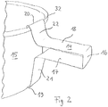
- the upper portion of the socket 20 comprises a holding portion 23, which is aligned in the direction of the lower portion of the socket. In the illustrated embodiment, this portion of the socket engages behind a bead 32 of the container. A radial slipping of the retaining clip 14 of the container 15 is made difficult.
- the lower portion of the socket has a holding portion 19 with a first portion 19a and a second portion 19b. The first portion 19 a is oriented in a direction facing away from the handle portion and is inclined toward the upper portion of the socket 20.
- the container is framed between the upper portion of the socket and the lower portion of the socket.
- a subsequent second portion 19b of the holder 19 is oriented in a direction away from the handle portion 16 and is inclined in a direction away from the upper portion of the socket 20 direction. Due to the different inclination of the two successive sections 19a and 19b, a latching lug 30 is formed.
- the locking lug 30 of the retaining clip 14 engages in a recess 31 at the bottom of the container 15 a. This locks the retaining clip on the container.
- Fig. 3 shows a sectional view of the retaining clip 14, which is in engagement with a cylindrical container 15, in which the legs 17, 18 are compressed (second connection state).
- the angles between the connecting portions 21, 22 and the legs 17, 18, as well as the angle between the connecting portions 21, 22 and the upper and lower portions of the socket 19, 30 are almost at right angles.
- the distance between the handle portion 16 and peripheral surface of the container 15 is significantly reduced. It is even possible that the connecting portions 21, 22 are partially in contact with the peripheral surface of the container 15 (not shown).
- the container 15 is held in position via the latching lug 30 in the lower region of the holder 19.
- a force is transmitted to the container 15 via a handle portion 16 facing portion 19a of the lower holding portion 19 and the lower connecting portion 21.
- the connecting portions 21, 22 now extend almost perpendicularly between the socket 19, 20 and the legs 17, 18 of the handle portion 16.
- the connection between the retaining clip 14 and the container 15 is secured against rotation. Both a rotation of the container 15, as well as a tilting of the container 15 due to gravity can be avoided by the stable connection.
- FIG. 2 is a schematic representation of a retaining clip 14 with a cylindrical container 15 according to an embodiment of the invention shown.
- the retaining clip 14 at any Place the container 15 are attached.
- An upper part of the socket 19 engages behind an upwardly projecting bead 32 at the top of the container 15.
- a lid of the container (not shown) in this way, even while the retaining clip 14 is engaged with the container 15, are easily removed.
- the legs 17, 18 have in this embodiment, the retaining clip 14 has a length of about 30 millimeters, so that the handle portion can be comfortably held with multiple fingers.
- the retaining clip 14 is transmitted by compressing the legs 17, 18, a voltage on the socket 19, 20 and the container clamped against rotation.
- the handling of the preserves 15 thus inserted into the retaining clip 14 takes place via the handle portion 16 acting as a handle with two opposite legs 17, 18.
- the holder can be arranged at any position of the preserve.
- the retaining clip is reusable, saves material and takes up little space.
Landscapes
- Engineering & Computer Science (AREA)
- Food Science & Technology (AREA)
- Details Of Rigid Or Semi-Rigid Containers (AREA)
Priority Applications (1)
| Application Number | Priority Date | Filing Date | Title |
|---|---|---|---|
| PL17179044T PL3266355T3 (pl) | 2016-07-07 | 2017-06-30 | Klamra trzymająca do pojemnika |
Applications Claiming Priority (1)
| Application Number | Priority Date | Filing Date | Title |
|---|---|---|---|
| DE202016004210.7U DE202016004210U1 (de) | 2016-07-07 | 2016-07-07 | Halteklammer für einen Behälter |
Publications (2)
| Publication Number | Publication Date |
|---|---|
| EP3266355A1 EP3266355A1 (de) | 2018-01-10 |
| EP3266355B1 true EP3266355B1 (de) | 2019-11-06 |
Family
ID=59285035
Family Applications (1)
| Application Number | Title | Priority Date | Filing Date |
|---|---|---|---|
| EP17179044.7A Active EP3266355B1 (de) | 2016-07-07 | 2017-06-30 | Halteklammer für einen behälter |
Country Status (5)
| Country | Link |
|---|---|
| EP (1) | EP3266355B1 (pl) |
| DE (1) | DE202016004210U1 (pl) |
| ES (1) | ES2769294T3 (pl) |
| PL (1) | PL3266355T3 (pl) |
| PT (1) | PT3266355T (pl) |
Family Cites Families (5)
| Publication number | Priority date | Publication date | Assignee | Title |
|---|---|---|---|---|
| US172848A (en) * | 1876-02-01 | Improvement in pan-lifters | ||
| US116330A (en) * | 1871-06-27 | Improvement in pan-lifters | ||
| US1183990A (en) * | 1915-02-19 | 1916-05-23 | William Henry Lau | Lard-pail. |
| US1505369A (en) * | 1922-05-08 | 1924-08-19 | Brown Sol | Dispensing can and handle therefor |
| US20040174028A1 (en) * | 2003-03-06 | 2004-09-09 | O'bannon Diane Lindley | Device for holding a hot dish |
-
2016
- 2016-07-07 DE DE202016004210.7U patent/DE202016004210U1/de active Active
-
2017
- 2017-06-30 ES ES17179044T patent/ES2769294T3/es active Active
- 2017-06-30 PL PL17179044T patent/PL3266355T3/pl unknown
- 2017-06-30 PT PT171790447T patent/PT3266355T/pt unknown
- 2017-06-30 EP EP17179044.7A patent/EP3266355B1/de active Active
Non-Patent Citations (1)
| Title |
|---|
| None * |
Also Published As
| Publication number | Publication date |
|---|---|
| DE202016004210U1 (de) | 2017-10-10 |
| ES2769294T3 (es) | 2020-06-25 |
| PT3266355T (pt) | 2020-02-04 |
| EP3266355A1 (de) | 2018-01-10 |
| PL3266355T3 (pl) | 2020-05-18 |
Similar Documents
| Publication | Publication Date | Title |
|---|---|---|
| WO2011022857A2 (de) | Haltevorrichtung für einen getränkebehälter | |
| DE1286813B (de) | Befestigungsvorrichtung fuer Schrauben | |
| EP0458254A2 (de) | Befestigungsvorrichtung zur Befestigung eines Griffelementes an einem Kochgeschirr | |
| DE102012107572B4 (de) | Adaptereinrichtung für einen Schubkasten | |
| DE102005024712B4 (de) | Federmutter | |
| DE102013211300B4 (de) | Kochfeld | |
| EP3266355A1 (de) | Halteklammer für einen behälter | |
| DE102010022215B4 (de) | Motorbefestigung insbesondere für ein Gargerät | |
| DE4335000C2 (de) | U-förmiges Verbindungselement zur Verbindung von C-Profilschienen aus Metall | |
| DE2230309C3 (de) | Befestigungsklammer für Leisten mit T-förmiger Aussparung und Verfahren zu ihrer Anbringung | |
| EP2218380B1 (de) | Kochgeschirr zum Kochen und Abgießen | |
| DE2046344C3 (de) | Vorrichtung zur Schnellbefestigung eines elektrischen Schaltgerätes | |
| EP0388575A1 (de) | Schneehalter | |
| DE102020129150B3 (de) | Topfförmiger Einsatz | |
| EP0389438B1 (de) | Schneehalter | |
| DE102012004324B4 (de) | Untersetzer für ein Koch- oder Backgeschirr | |
| DE102015013344B4 (de) | Vorrichtung zur befestigung eines objektes an einem oder mehreren trägerstoffen | |
| EP1517629A1 (de) | Abdeckung f r ein kochgeschirr | |
| DE9317660U1 (de) | Regal | |
| EP2620712B1 (de) | Aushebesicherung für eine Konsole | |
| DE613405C (de) | Fuer Eiserzeuger bestimmter Zellensatz | |
| EP1258219B1 (de) | Speisentransportbehälter | |
| DE2049286C3 (de) | Regal | |
| DE7100680U (de) | Tragarm | |
| DE1924127C3 (de) | Tragvorrichtung zum Einstecken in Lochplatten |
Legal Events
| Date | Code | Title | Description |
|---|---|---|---|
| PUAI | Public reference made under article 153(3) epc to a published international application that has entered the european phase |
Free format text: ORIGINAL CODE: 0009012 |
|
| STAA | Information on the status of an ep patent application or granted ep patent |
Free format text: STATUS: THE APPLICATION HAS BEEN PUBLISHED |
|
| AK | Designated contracting states |
Kind code of ref document: A1 Designated state(s): AL AT BE BG CH CY CZ DE DK EE ES FI FR GB GR HR HU IE IS IT LI LT LU LV MC MK MT NL NO PL PT RO RS SE SI SK SM TR |
|
| AX | Request for extension of the european patent |
Extension state: BA ME |
|
| RIN1 | Information on inventor provided before grant (corrected) |
Inventor name: ROBERTO STEIN |
|
| STAA | Information on the status of an ep patent application or granted ep patent |
Free format text: STATUS: REQUEST FOR EXAMINATION WAS MADE |
|
| 17P | Request for examination filed |
Effective date: 20180705 |
|
| RBV | Designated contracting states (corrected) |
Designated state(s): AL AT BE BG CH CY CZ DE DK EE ES FI FR GB GR HR HU IE IS IT LI LT LU LV MC MK MT NL NO PL PT RO RS SE SI SK SM TR |
|
| STAA | Information on the status of an ep patent application or granted ep patent |
Free format text: STATUS: EXAMINATION IS IN PROGRESS |
|
| 17Q | First examination report despatched |
Effective date: 20181102 |
|
| GRAP | Despatch of communication of intention to grant a patent |
Free format text: ORIGINAL CODE: EPIDOSNIGR1 |
|
| STAA | Information on the status of an ep patent application or granted ep patent |
Free format text: STATUS: GRANT OF PATENT IS INTENDED |
|
| INTG | Intention to grant announced |
Effective date: 20190603 |
|
| GRAS | Grant fee paid |
Free format text: ORIGINAL CODE: EPIDOSNIGR3 |
|
| GRAA | (expected) grant |
Free format text: ORIGINAL CODE: 0009210 |
|
| STAA | Information on the status of an ep patent application or granted ep patent |
Free format text: STATUS: THE PATENT HAS BEEN GRANTED |
|
| AK | Designated contracting states |
Kind code of ref document: B1 Designated state(s): AL AT BE BG CH CY CZ DE DK EE ES FI FR GB GR HR HU IE IS IT LI LT LU LV MC MK MT NL NO PL PT RO RS SE SI SK SM TR |
|
| REG | Reference to a national code |
Ref country code: GB Ref legal event code: FG4D Free format text: NOT ENGLISH |
|
| REG | Reference to a national code |
Ref country code: CH Ref legal event code: EP Ref country code: AT Ref legal event code: REF Ref document number: 1197640 Country of ref document: AT Kind code of ref document: T Effective date: 20191115 |
|
| REG | Reference to a national code |
Ref country code: DE Ref legal event code: R096 Ref document number: 502017002770 Country of ref document: DE |
|
| REG | Reference to a national code |
Ref country code: IE Ref legal event code: FG4D Free format text: LANGUAGE OF EP DOCUMENT: GERMAN |
|
| REG | Reference to a national code |
Ref country code: PT Ref legal event code: SC4A Ref document number: 3266355 Country of ref document: PT Date of ref document: 20200204 Kind code of ref document: T Free format text: AVAILABILITY OF NATIONAL TRANSLATION Effective date: 20200128 |
|
| REG | Reference to a national code |
Ref country code: NL Ref legal event code: MP Effective date: 20191106 |
|
| REG | Reference to a national code |
Ref country code: LT Ref legal event code: MG4D |
|
| PG25 | Lapsed in a contracting state [announced via postgrant information from national office to epo] |
Ref country code: SE Free format text: LAPSE BECAUSE OF FAILURE TO SUBMIT A TRANSLATION OF THE DESCRIPTION OR TO PAY THE FEE WITHIN THE PRESCRIBED TIME-LIMIT Effective date: 20191106 Ref country code: LV Free format text: LAPSE BECAUSE OF FAILURE TO SUBMIT A TRANSLATION OF THE DESCRIPTION OR TO PAY THE FEE WITHIN THE PRESCRIBED TIME-LIMIT Effective date: 20191106 Ref country code: FI Free format text: LAPSE BECAUSE OF FAILURE TO SUBMIT A TRANSLATION OF THE DESCRIPTION OR TO PAY THE FEE WITHIN THE PRESCRIBED TIME-LIMIT Effective date: 20191106 Ref country code: BG Free format text: LAPSE BECAUSE OF FAILURE TO SUBMIT A TRANSLATION OF THE DESCRIPTION OR TO PAY THE FEE WITHIN THE PRESCRIBED TIME-LIMIT Effective date: 20200206 Ref country code: NO Free format text: LAPSE BECAUSE OF FAILURE TO SUBMIT A TRANSLATION OF THE DESCRIPTION OR TO PAY THE FEE WITHIN THE PRESCRIBED TIME-LIMIT Effective date: 20200206 Ref country code: GR Free format text: LAPSE BECAUSE OF FAILURE TO SUBMIT A TRANSLATION OF THE DESCRIPTION OR TO PAY THE FEE WITHIN THE PRESCRIBED TIME-LIMIT Effective date: 20200207 Ref country code: LT Free format text: LAPSE BECAUSE OF FAILURE TO SUBMIT A TRANSLATION OF THE DESCRIPTION OR TO PAY THE FEE WITHIN THE PRESCRIBED TIME-LIMIT Effective date: 20191106 Ref country code: NL Free format text: LAPSE BECAUSE OF FAILURE TO SUBMIT A TRANSLATION OF THE DESCRIPTION OR TO PAY THE FEE WITHIN THE PRESCRIBED TIME-LIMIT Effective date: 20191106 |
|
| PG25 | Lapsed in a contracting state [announced via postgrant information from national office to epo] |
Ref country code: HR Free format text: LAPSE BECAUSE OF FAILURE TO SUBMIT A TRANSLATION OF THE DESCRIPTION OR TO PAY THE FEE WITHIN THE PRESCRIBED TIME-LIMIT Effective date: 20191106 Ref country code: IS Free format text: LAPSE BECAUSE OF FAILURE TO SUBMIT A TRANSLATION OF THE DESCRIPTION OR TO PAY THE FEE WITHIN THE PRESCRIBED TIME-LIMIT Effective date: 20200306 Ref country code: RS Free format text: LAPSE BECAUSE OF FAILURE TO SUBMIT A TRANSLATION OF THE DESCRIPTION OR TO PAY THE FEE WITHIN THE PRESCRIBED TIME-LIMIT Effective date: 20191106 |
|
| REG | Reference to a national code |
Ref country code: ES Ref legal event code: FG2A Ref document number: 2769294 Country of ref document: ES Kind code of ref document: T3 Effective date: 20200625 |
|
| PG25 | Lapsed in a contracting state [announced via postgrant information from national office to epo] |
Ref country code: AL Free format text: LAPSE BECAUSE OF FAILURE TO SUBMIT A TRANSLATION OF THE DESCRIPTION OR TO PAY THE FEE WITHIN THE PRESCRIBED TIME-LIMIT Effective date: 20191106 |
|
| PG25 | Lapsed in a contracting state [announced via postgrant information from national office to epo] |
Ref country code: RO Free format text: LAPSE BECAUSE OF FAILURE TO SUBMIT A TRANSLATION OF THE DESCRIPTION OR TO PAY THE FEE WITHIN THE PRESCRIBED TIME-LIMIT Effective date: 20191106 Ref country code: CZ Free format text: LAPSE BECAUSE OF FAILURE TO SUBMIT A TRANSLATION OF THE DESCRIPTION OR TO PAY THE FEE WITHIN THE PRESCRIBED TIME-LIMIT Effective date: 20191106 Ref country code: EE Free format text: LAPSE BECAUSE OF FAILURE TO SUBMIT A TRANSLATION OF THE DESCRIPTION OR TO PAY THE FEE WITHIN THE PRESCRIBED TIME-LIMIT Effective date: 20191106 Ref country code: DK Free format text: LAPSE BECAUSE OF FAILURE TO SUBMIT A TRANSLATION OF THE DESCRIPTION OR TO PAY THE FEE WITHIN THE PRESCRIBED TIME-LIMIT Effective date: 20191106 |
|
| REG | Reference to a national code |
Ref country code: DE Ref legal event code: R097 Ref document number: 502017002770 Country of ref document: DE |
|
| PG25 | Lapsed in a contracting state [announced via postgrant information from national office to epo] |
Ref country code: SK Free format text: LAPSE BECAUSE OF FAILURE TO SUBMIT A TRANSLATION OF THE DESCRIPTION OR TO PAY THE FEE WITHIN THE PRESCRIBED TIME-LIMIT Effective date: 20191106 Ref country code: SM Free format text: LAPSE BECAUSE OF FAILURE TO SUBMIT A TRANSLATION OF THE DESCRIPTION OR TO PAY THE FEE WITHIN THE PRESCRIBED TIME-LIMIT Effective date: 20191106 |
|
| PLBE | No opposition filed within time limit |
Free format text: ORIGINAL CODE: 0009261 |
|
| STAA | Information on the status of an ep patent application or granted ep patent |
Free format text: STATUS: NO OPPOSITION FILED WITHIN TIME LIMIT |
|
| 26N | No opposition filed |
Effective date: 20200807 |
|
| PG25 | Lapsed in a contracting state [announced via postgrant information from national office to epo] |
Ref country code: SI Free format text: LAPSE BECAUSE OF FAILURE TO SUBMIT A TRANSLATION OF THE DESCRIPTION OR TO PAY THE FEE WITHIN THE PRESCRIBED TIME-LIMIT Effective date: 20191106 |
|
| PG25 | Lapsed in a contracting state [announced via postgrant information from national office to epo] |
Ref country code: MC Free format text: LAPSE BECAUSE OF FAILURE TO SUBMIT A TRANSLATION OF THE DESCRIPTION OR TO PAY THE FEE WITHIN THE PRESCRIBED TIME-LIMIT Effective date: 20191106 |
|
| REG | Reference to a national code |
Ref country code: CH Ref legal event code: PL |
|
| PG25 | Lapsed in a contracting state [announced via postgrant information from national office to epo] |
Ref country code: LU Free format text: LAPSE BECAUSE OF NON-PAYMENT OF DUE FEES Effective date: 20200630 |
|
| PG25 | Lapsed in a contracting state [announced via postgrant information from national office to epo] |
Ref country code: IE Free format text: LAPSE BECAUSE OF NON-PAYMENT OF DUE FEES Effective date: 20200630 Ref country code: LI Free format text: LAPSE BECAUSE OF NON-PAYMENT OF DUE FEES Effective date: 20200630 Ref country code: CH Free format text: LAPSE BECAUSE OF NON-PAYMENT OF DUE FEES Effective date: 20200630 |
|
| PG25 | Lapsed in a contracting state [announced via postgrant information from national office to epo] |
Ref country code: TR Free format text: LAPSE BECAUSE OF FAILURE TO SUBMIT A TRANSLATION OF THE DESCRIPTION OR TO PAY THE FEE WITHIN THE PRESCRIBED TIME-LIMIT Effective date: 20191106 Ref country code: MT Free format text: LAPSE BECAUSE OF FAILURE TO SUBMIT A TRANSLATION OF THE DESCRIPTION OR TO PAY THE FEE WITHIN THE PRESCRIBED TIME-LIMIT Effective date: 20191106 Ref country code: CY Free format text: LAPSE BECAUSE OF FAILURE TO SUBMIT A TRANSLATION OF THE DESCRIPTION OR TO PAY THE FEE WITHIN THE PRESCRIBED TIME-LIMIT Effective date: 20191106 |
|
| PG25 | Lapsed in a contracting state [announced via postgrant information from national office to epo] |
Ref country code: MK Free format text: LAPSE BECAUSE OF FAILURE TO SUBMIT A TRANSLATION OF THE DESCRIPTION OR TO PAY THE FEE WITHIN THE PRESCRIBED TIME-LIMIT Effective date: 20191106 |
|
| REG | Reference to a national code |
Ref country code: AT Ref legal event code: MM01 Ref document number: 1197640 Country of ref document: AT Kind code of ref document: T Effective date: 20220630 |
|
| PG25 | Lapsed in a contracting state [announced via postgrant information from national office to epo] |
Ref country code: AT Free format text: LAPSE BECAUSE OF NON-PAYMENT OF DUE FEES Effective date: 20220630 |
|
| PGFP | Annual fee paid to national office [announced via postgrant information from national office to epo] |
Ref country code: PL Payment date: 20250624 Year of fee payment: 9 Ref country code: DE Payment date: 20250624 Year of fee payment: 9 |
|
| PGFP | Annual fee paid to national office [announced via postgrant information from national office to epo] |
Ref country code: GB Payment date: 20250620 Year of fee payment: 9 |
|
| PGFP | Annual fee paid to national office [announced via postgrant information from national office to epo] |
Ref country code: BE Payment date: 20250617 Year of fee payment: 9 |
|
| PGFP | Annual fee paid to national office [announced via postgrant information from national office to epo] |
Ref country code: PT Payment date: 20250622 Year of fee payment: 9 |
|
| PGFP | Annual fee paid to national office [announced via postgrant information from national office to epo] |
Ref country code: FR Payment date: 20250618 Year of fee payment: 9 |
|
| PGFP | Annual fee paid to national office [announced via postgrant information from national office to epo] |
Ref country code: ES Payment date: 20250718 Year of fee payment: 9 |
|
| PGFP | Annual fee paid to national office [announced via postgrant information from national office to epo] |
Ref country code: IT Payment date: 20250630 Year of fee payment: 9 |