EP3265757B1 - Method and apparatus for optical sensing - Google Patents
Method and apparatus for optical sensing Download PDFInfo
- Publication number
- EP3265757B1 EP3265757B1 EP16709553.8A EP16709553A EP3265757B1 EP 3265757 B1 EP3265757 B1 EP 3265757B1 EP 16709553 A EP16709553 A EP 16709553A EP 3265757 B1 EP3265757 B1 EP 3265757B1
- Authority
- EP
- European Patent Office
- Prior art keywords
- fiber
- reflector
- optical
- reflectors
- along
- Prior art date
- Legal status (The legal status is an assumption and is not a legal conclusion. Google has not performed a legal analysis and makes no representation as to the accuracy of the status listed.)
- Active
Links
- 230000003287 optical effect Effects 0.000 title claims description 118
- 238000000034 method Methods 0.000 title description 23
- 239000000835 fiber Substances 0.000 claims description 233
- 239000013307 optical fiber Substances 0.000 claims description 50
- 238000002310 reflectometry Methods 0.000 claims description 45
- 238000000926 separation method Methods 0.000 claims description 16
- 230000009977 dual effect Effects 0.000 claims description 9
- 230000001419 dependent effect Effects 0.000 claims description 6
- 238000010586 diagram Methods 0.000 description 20
- 230000035945 sensitivity Effects 0.000 description 20
- 238000005259 measurement Methods 0.000 description 19
- 230000003111 delayed effect Effects 0.000 description 13
- 230000008901 benefit Effects 0.000 description 10
- 230000008859 change Effects 0.000 description 10
- 238000005070 sampling Methods 0.000 description 10
- 230000000694 effects Effects 0.000 description 9
- 230000005540 biological transmission Effects 0.000 description 7
- 230000006872 improvement Effects 0.000 description 7
- 238000012545 processing Methods 0.000 description 7
- 238000001228 spectrum Methods 0.000 description 7
- 238000001514 detection method Methods 0.000 description 5
- 238000005516 engineering process Methods 0.000 description 5
- 238000012986 modification Methods 0.000 description 5
- 230000004048 modification Effects 0.000 description 5
- 230000010363 phase shift Effects 0.000 description 5
- 230000008569 process Effects 0.000 description 5
- 230000004044 response Effects 0.000 description 5
- 230000002269 spontaneous effect Effects 0.000 description 5
- 239000003129 oil well Substances 0.000 description 4
- 230000001902 propagating effect Effects 0.000 description 4
- 238000012935 Averaging Methods 0.000 description 3
- 101150067325 DAS1 gene Proteins 0.000 description 3
- 241000188250 Idas Species 0.000 description 3
- 101150057104 MCIDAS gene Proteins 0.000 description 3
- 101100008874 Saccharomyces cerevisiae (strain ATCC 204508 / S288c) DAS2 gene Proteins 0.000 description 3
- 101100516268 Saccharomyces cerevisiae (strain ATCC 204508 / S288c) NDT80 gene Proteins 0.000 description 3
- 238000007792 addition Methods 0.000 description 3
- 238000005253 cladding Methods 0.000 description 3
- 238000013461 design Methods 0.000 description 3
- 238000009434 installation Methods 0.000 description 3
- 238000012544 monitoring process Methods 0.000 description 3
- 230000000630 rising effect Effects 0.000 description 3
- 108010014172 Factor V Proteins 0.000 description 2
- 238000013459 approach Methods 0.000 description 2
- 230000035559 beat frequency Effects 0.000 description 2
- 230000008878 coupling Effects 0.000 description 2
- 238000010168 coupling process Methods 0.000 description 2
- 238000005859 coupling reaction Methods 0.000 description 2
- 239000012530 fluid Substances 0.000 description 2
- 230000006870 function Effects 0.000 description 2
- 238000007620 mathematical function Methods 0.000 description 2
- 238000003672 processing method Methods 0.000 description 2
- 230000003068 static effect Effects 0.000 description 2
- 238000012360 testing method Methods 0.000 description 2
- 230000005534 acoustic noise Effects 0.000 description 1
- 230000004075 alteration Effects 0.000 description 1
- 230000009286 beneficial effect Effects 0.000 description 1
- 230000002457 bidirectional effect Effects 0.000 description 1
- 238000009529 body temperature measurement Methods 0.000 description 1
- 230000001427 coherent effect Effects 0.000 description 1
- 230000006835 compression Effects 0.000 description 1
- 238000007906 compression Methods 0.000 description 1
- 238000012937 correction Methods 0.000 description 1
- 238000012217 deletion Methods 0.000 description 1
- 230000037430 deletion Effects 0.000 description 1
- 238000005562 fading Methods 0.000 description 1
- 238000012681 fiber drawing Methods 0.000 description 1
- 239000011521 glass Substances 0.000 description 1
- 238000005286 illumination Methods 0.000 description 1
- 239000000203 mixture Substances 0.000 description 1
- 230000008450 motivation Effects 0.000 description 1
- 238000010606 normalization Methods 0.000 description 1
- 238000011002 quantification Methods 0.000 description 1
- 230000009467 reduction Effects 0.000 description 1
- 238000011160 research Methods 0.000 description 1
- 238000006467 substitution reaction Methods 0.000 description 1
- 230000001360 synchronised effect Effects 0.000 description 1
- 230000009466 transformation Effects 0.000 description 1
Images


Classifications
-
- G—PHYSICS
- G01—MEASURING; TESTING
- G01D—MEASURING NOT SPECIALLY ADAPTED FOR A SPECIFIC VARIABLE; ARRANGEMENTS FOR MEASURING TWO OR MORE VARIABLES NOT COVERED IN A SINGLE OTHER SUBCLASS; TARIFF METERING APPARATUS; MEASURING OR TESTING NOT OTHERWISE PROVIDED FOR
- G01D5/00—Mechanical means for transferring the output of a sensing member; Means for converting the output of a sensing member to another variable where the form or nature of the sensing member does not constrain the means for converting; Transducers not specially adapted for a specific variable
- G01D5/26—Mechanical means for transferring the output of a sensing member; Means for converting the output of a sensing member to another variable where the form or nature of the sensing member does not constrain the means for converting; Transducers not specially adapted for a specific variable characterised by optical transfer means, i.e. using infrared, visible, or ultraviolet light
- G01D5/32—Mechanical means for transferring the output of a sensing member; Means for converting the output of a sensing member to another variable where the form or nature of the sensing member does not constrain the means for converting; Transducers not specially adapted for a specific variable characterised by optical transfer means, i.e. using infrared, visible, or ultraviolet light with attenuation or whole or partial obturation of beams of light
- G01D5/34—Mechanical means for transferring the output of a sensing member; Means for converting the output of a sensing member to another variable where the form or nature of the sensing member does not constrain the means for converting; Transducers not specially adapted for a specific variable characterised by optical transfer means, i.e. using infrared, visible, or ultraviolet light with attenuation or whole or partial obturation of beams of light the beams of light being detected by photocells
- G01D5/353—Mechanical means for transferring the output of a sensing member; Means for converting the output of a sensing member to another variable where the form or nature of the sensing member does not constrain the means for converting; Transducers not specially adapted for a specific variable characterised by optical transfer means, i.e. using infrared, visible, or ultraviolet light with attenuation or whole or partial obturation of beams of light the beams of light being detected by photocells influencing the transmission properties of an optical fibre
- G01D5/3537—Optical fibre sensor using a particular arrangement of the optical fibre itself
-
- G—PHYSICS
- G01—MEASURING; TESTING
- G01D—MEASURING NOT SPECIALLY ADAPTED FOR A SPECIFIC VARIABLE; ARRANGEMENTS FOR MEASURING TWO OR MORE VARIABLES NOT COVERED IN A SINGLE OTHER SUBCLASS; TARIFF METERING APPARATUS; MEASURING OR TESTING NOT OTHERWISE PROVIDED FOR
- G01D5/00—Mechanical means for transferring the output of a sensing member; Means for converting the output of a sensing member to another variable where the form or nature of the sensing member does not constrain the means for converting; Transducers not specially adapted for a specific variable
- G01D5/26—Mechanical means for transferring the output of a sensing member; Means for converting the output of a sensing member to another variable where the form or nature of the sensing member does not constrain the means for converting; Transducers not specially adapted for a specific variable characterised by optical transfer means, i.e. using infrared, visible, or ultraviolet light
- G01D5/32—Mechanical means for transferring the output of a sensing member; Means for converting the output of a sensing member to another variable where the form or nature of the sensing member does not constrain the means for converting; Transducers not specially adapted for a specific variable characterised by optical transfer means, i.e. using infrared, visible, or ultraviolet light with attenuation or whole or partial obturation of beams of light
- G01D5/34—Mechanical means for transferring the output of a sensing member; Means for converting the output of a sensing member to another variable where the form or nature of the sensing member does not constrain the means for converting; Transducers not specially adapted for a specific variable characterised by optical transfer means, i.e. using infrared, visible, or ultraviolet light with attenuation or whole or partial obturation of beams of light the beams of light being detected by photocells
- G01D5/353—Mechanical means for transferring the output of a sensing member; Means for converting the output of a sensing member to another variable where the form or nature of the sensing member does not constrain the means for converting; Transducers not specially adapted for a specific variable characterised by optical transfer means, i.e. using infrared, visible, or ultraviolet light with attenuation or whole or partial obturation of beams of light the beams of light being detected by photocells influencing the transmission properties of an optical fibre
- G01D5/35306—Mechanical means for transferring the output of a sensing member; Means for converting the output of a sensing member to another variable where the form or nature of the sensing member does not constrain the means for converting; Transducers not specially adapted for a specific variable characterised by optical transfer means, i.e. using infrared, visible, or ultraviolet light with attenuation or whole or partial obturation of beams of light the beams of light being detected by photocells influencing the transmission properties of an optical fibre using an interferometer arrangement
- G01D5/35309—Mechanical means for transferring the output of a sensing member; Means for converting the output of a sensing member to another variable where the form or nature of the sensing member does not constrain the means for converting; Transducers not specially adapted for a specific variable characterised by optical transfer means, i.e. using infrared, visible, or ultraviolet light with attenuation or whole or partial obturation of beams of light the beams of light being detected by photocells influencing the transmission properties of an optical fibre using an interferometer arrangement using multiple waves interferometer
- G01D5/35316—Mechanical means for transferring the output of a sensing member; Means for converting the output of a sensing member to another variable where the form or nature of the sensing member does not constrain the means for converting; Transducers not specially adapted for a specific variable characterised by optical transfer means, i.e. using infrared, visible, or ultraviolet light with attenuation or whole or partial obturation of beams of light the beams of light being detected by photocells influencing the transmission properties of an optical fibre using an interferometer arrangement using multiple waves interferometer using a Bragg gratings
-
- G—PHYSICS
- G01—MEASURING; TESTING
- G01D—MEASURING NOT SPECIALLY ADAPTED FOR A SPECIFIC VARIABLE; ARRANGEMENTS FOR MEASURING TWO OR MORE VARIABLES NOT COVERED IN A SINGLE OTHER SUBCLASS; TARIFF METERING APPARATUS; MEASURING OR TESTING NOT OTHERWISE PROVIDED FOR
- G01D5/00—Mechanical means for transferring the output of a sensing member; Means for converting the output of a sensing member to another variable where the form or nature of the sensing member does not constrain the means for converting; Transducers not specially adapted for a specific variable
- G01D5/26—Mechanical means for transferring the output of a sensing member; Means for converting the output of a sensing member to another variable where the form or nature of the sensing member does not constrain the means for converting; Transducers not specially adapted for a specific variable characterised by optical transfer means, i.e. using infrared, visible, or ultraviolet light
- G01D5/32—Mechanical means for transferring the output of a sensing member; Means for converting the output of a sensing member to another variable where the form or nature of the sensing member does not constrain the means for converting; Transducers not specially adapted for a specific variable characterised by optical transfer means, i.e. using infrared, visible, or ultraviolet light with attenuation or whole or partial obturation of beams of light
- G01D5/34—Mechanical means for transferring the output of a sensing member; Means for converting the output of a sensing member to another variable where the form or nature of the sensing member does not constrain the means for converting; Transducers not specially adapted for a specific variable characterised by optical transfer means, i.e. using infrared, visible, or ultraviolet light with attenuation or whole or partial obturation of beams of light the beams of light being detected by photocells
- G01D5/353—Mechanical means for transferring the output of a sensing member; Means for converting the output of a sensing member to another variable where the form or nature of the sensing member does not constrain the means for converting; Transducers not specially adapted for a specific variable characterised by optical transfer means, i.e. using infrared, visible, or ultraviolet light with attenuation or whole or partial obturation of beams of light the beams of light being detected by photocells influencing the transmission properties of an optical fibre
- G01D5/35306—Mechanical means for transferring the output of a sensing member; Means for converting the output of a sensing member to another variable where the form or nature of the sensing member does not constrain the means for converting; Transducers not specially adapted for a specific variable characterised by optical transfer means, i.e. using infrared, visible, or ultraviolet light with attenuation or whole or partial obturation of beams of light the beams of light being detected by photocells influencing the transmission properties of an optical fibre using an interferometer arrangement
-
- G—PHYSICS
- G01—MEASURING; TESTING
- G01D—MEASURING NOT SPECIALLY ADAPTED FOR A SPECIFIC VARIABLE; ARRANGEMENTS FOR MEASURING TWO OR MORE VARIABLES NOT COVERED IN A SINGLE OTHER SUBCLASS; TARIFF METERING APPARATUS; MEASURING OR TESTING NOT OTHERWISE PROVIDED FOR
- G01D5/00—Mechanical means for transferring the output of a sensing member; Means for converting the output of a sensing member to another variable where the form or nature of the sensing member does not constrain the means for converting; Transducers not specially adapted for a specific variable
- G01D5/26—Mechanical means for transferring the output of a sensing member; Means for converting the output of a sensing member to another variable where the form or nature of the sensing member does not constrain the means for converting; Transducers not specially adapted for a specific variable characterised by optical transfer means, i.e. using infrared, visible, or ultraviolet light
- G01D5/32—Mechanical means for transferring the output of a sensing member; Means for converting the output of a sensing member to another variable where the form or nature of the sensing member does not constrain the means for converting; Transducers not specially adapted for a specific variable characterised by optical transfer means, i.e. using infrared, visible, or ultraviolet light with attenuation or whole or partial obturation of beams of light
- G01D5/34—Mechanical means for transferring the output of a sensing member; Means for converting the output of a sensing member to another variable where the form or nature of the sensing member does not constrain the means for converting; Transducers not specially adapted for a specific variable characterised by optical transfer means, i.e. using infrared, visible, or ultraviolet light with attenuation or whole or partial obturation of beams of light the beams of light being detected by photocells
- G01D5/353—Mechanical means for transferring the output of a sensing member; Means for converting the output of a sensing member to another variable where the form or nature of the sensing member does not constrain the means for converting; Transducers not specially adapted for a specific variable characterised by optical transfer means, i.e. using infrared, visible, or ultraviolet light with attenuation or whole or partial obturation of beams of light the beams of light being detected by photocells influencing the transmission properties of an optical fibre
- G01D5/3537—Optical fibre sensor using a particular arrangement of the optical fibre itself
- G01D5/35374—Particular layout of the fiber
-
- G—PHYSICS
- G01—MEASURING; TESTING
- G01H—MEASUREMENT OF MECHANICAL VIBRATIONS OR ULTRASONIC, SONIC OR INFRASONIC WAVES
- G01H9/00—Measuring mechanical vibrations or ultrasonic, sonic or infrasonic waves by using radiation-sensitive means, e.g. optical means
- G01H9/004—Measuring mechanical vibrations or ultrasonic, sonic or infrasonic waves by using radiation-sensitive means, e.g. optical means using fibre optic sensors
-
- G—PHYSICS
- G02—OPTICS
- G02B—OPTICAL ELEMENTS, SYSTEMS OR APPARATUS
- G02B6/00—Light guides; Structural details of arrangements comprising light guides and other optical elements, e.g. couplings
- G02B6/02—Optical fibres with cladding with or without a coating
- G02B6/02057—Optical fibres with cladding with or without a coating comprising gratings
- G02B6/02076—Refractive index modulation gratings, e.g. Bragg gratings
- G02B6/0208—Refractive index modulation gratings, e.g. Bragg gratings characterised by their structure, wavelength response
- G02B6/02085—Refractive index modulation gratings, e.g. Bragg gratings characterised by their structure, wavelength response characterised by the grating profile, e.g. chirped, apodised, tilted, helical
-
- E—FIXED CONSTRUCTIONS
- E21—EARTH DRILLING; MINING
- E21B—EARTH DRILLING, e.g. DEEP DRILLING; OBTAINING OIL, GAS, WATER, SOLUBLE OR MELTABLE MATERIALS OR A SLURRY OF MINERALS FROM WELLS
- E21B47/00—Survey of boreholes or wells
- E21B47/12—Means for transmitting measuring-signals or control signals from the well to the surface, or from the surface to the well, e.g. for logging while drilling
- E21B47/13—Means for transmitting measuring-signals or control signals from the well to the surface, or from the surface to the well, e.g. for logging while drilling by electromagnetic energy, e.g. radio frequency
- E21B47/135—Means for transmitting measuring-signals or control signals from the well to the surface, or from the surface to the well, e.g. for logging while drilling by electromagnetic energy, e.g. radio frequency using light waves, e.g. infrared or ultraviolet waves
-
- G—PHYSICS
- G01—MEASURING; TESTING
- G01V—GEOPHYSICS; GRAVITATIONAL MEASUREMENTS; DETECTING MASSES OR OBJECTS; TAGS
- G01V8/00—Prospecting or detecting by optical means
- G01V8/10—Detecting, e.g. by using light barriers
- G01V8/12—Detecting, e.g. by using light barriers using one transmitter and one receiver
- G01V8/16—Detecting, e.g. by using light barriers using one transmitter and one receiver using optical fibres
Definitions
- Embodiments of the present invention relate to distributed optical fibre sensors, and in particular in some embodiments to such sensors with reflective elements integrated into the sensing optical fiber.
- Optical fiber based distributed sensor systems are finding many applications, in particular in the oil and gas industry for flow monitoring and seismic detection, and in the security industry for area or perimeter security monitoring, or monitoring along a long line such as a pipeline or railway line.
- the present applicant, Silixa Ltd, of Elstree, London markets two optical fiber distributed sensing systems, the Silixa® iDASTM system, which is a very sensitive optical fiber distributed acoustic sensor, and the Silixa® UltimaTM system, which is a distributed optical fiber based temperature sensor.
- the Silixa® iDASTM system is presently class leading in terms of spatial resolution, frequency response, and sensitivity and is capable of resolving individual acoustic signals with a spatial resolution of down to 1m along the length of the fiber, at frequencies up to 100kHz. However, it is always desirable to try and improve the performance in terms of the any of the resolution, frequency response, or sensitivity parameters noted.
- WO 89/02067 A1 describes varying the reflection coefficients of partially reflective splices or discontinuities along a fiber sensor.
- Embodiments of the invention provide an improved optical fiber distributed acoustic sensor system that makes use of a specially designed optical fiber to improve overall sensitivity of the system, in some embodiments by a factor in excess of 10. This is achieved by inserting into the fiber weak (by which we mean of low reflectivity) broadband reflectors periodically along the fiber.
- the reflectors reflect only a small proportion of the light from the DAS incident thereon back along the fiber, typically in the region of 0.001% to 0.1%, but preferably around 0.01% reflectivity per reflector.
- the reflection bandwidth is relatively broadband i.e. equal or greater than the region of +/- 2nm, preferably as large as +/-5nm from the nominal laser wavelength.
- the reflectors are formed from gratings, that are known to often exhibit temperature dependence of the reflected wavelength over a broad e.g. +/-2nm bandwidth.
- the reflectors are formed from a series of fiber Bragg gratings, each with a different center reflecting frequency, the reflecting frequencies and bandwidths of the gratings being selected to provide the broadband reflection.
- a chirped grating may also be used to provide the same effect.
- a short grating with low reflectivity and broad bandwidth may be written into the sensing fibre using femtosecond laser writing process.
- the reflectors are spaced at the gauge length i.e. the desired spatial resolution of the optical fiber DAS, in other embodiments the reflectors are spaced at a distance calculated in dependence on the gauge length, for example as a fraction or multiple thereof.
- some embodiments allow for either dual spatial resolution operation, or spatial resolution selectivity. These effects are obtained by controlling the virtual timing characteristics between the reflections obtained from the reflectors as an optical pulse travels along the optical fiber.
- an optical pulse is launched along the fiber and reflects from the reflectors in turn as it travels therealong. These reflections are received at a distributed acoustic sensing system, and are subject to a known delay, to provide a delayed version of the reflections, which is then interfered with the non-delayed version to obtain an output signal.
- the delay applied is referred to as the gauge length.
- the delayed version can therefore be thought of as a virtual pulse that "follows" the actual pulse, but separated therefrom by the gauge length.
- the delay, or gauge length, between the actual pulse and the virtual pulse defines the spatial resolution that is obtained from the system.
- the gauge length may be controlled such that the effective pulse separation (i.e. the timing difference or delay between the original pulse and the delayed pulse) is adjusted to encompass a desired pair of reflector portions, for example to alter the spatial resolution as desired.
- Dual spatial resolution operation is obtained by setting the gauge length to particular values that mean that first and second sensing resolutions are obtained alternately as a pulse travels along the fiber.
- an optical fiber distributed acoustic sensor system comprising: an optical source arranged in use to produce optical signal pulses; an optical fiber deployable in use in a sensing environment and arranged in use to receive the optical signal pulses; and sensing apparatus arranged in use to detect light from the optical signal pulses reflected back along the optical fiber and to determine acoustic signals incident on the optical fiber in dependence on the reflected light; the system being characterized in that the optical fiber comprises a plurality of reflector portions regularly distributed along its length in at least a first sensing region thereof.
- Embodiments of the invention provide an improved optical fiber distributed sensor, and in some embodiments an optical fiber distributed acoustic sensor that improves on the Silixa® iDASTM system described in WO 2010/136810 , by improving the signal to noise ratio.
- This is accomplished by using a sensing fiber having a number of weak, relatively broadband reflection points along the length thereof, spaced generally at the same distance as the gauge length, being the path length delay applied to the reflected pulse in one arm of the interferometer of the DAS system, and which in turn relates to the spatial resolution obtained. Due to the weak reflectivity (around 0.01% reflectivity is envisaged), the reflection loss along the fiber is small, and hence thousands of reflection point may be introduced.
- a series of Fiber Bragg Gratings are used for each reflection point, with a different peak reflection wavelength but with overlapping reflection bandwidths, the gratings being written into the fiber next to each other, separated by a small amount, of the order of 5 to 15 mm, and preferably around 10mm.
- the total length of each reflection point is around 45mm, and the total reflection bandwidth allowing for the overlapping reflection bandwidths of the individual gratings is around +/- 2nm, although in some embodiments it can be as wide as at least +/- 5nm.
- a single, relatively weak broadband reflector would be used; for example a chirped grating or a short, broadband, weakly reflecting mirror less than 1mm and typically 100 ⁇ m in length. Further embodiments are described below.
- a simultaneous dual-resolution arrangement can be provided, by selection of appropriate gauge length and pulse width with respect to the spacing of the reflector portions along the fiber. For example, for a given reflector spacing L , provided the pulse width is less than L , for example around 0.75 L , and further provided that the gauge length, i.e. the difference in length between different arms of the interferometer in the DAS, which in turn relates to the spatial resolution, is chosen such that the reflected light and the delayed version thereof in the interferometer have been consecutively reflected from neighbouring reflection points and then non-neighbouring reflection points, then multi-resolution performance will be successively obtained.
- the control of pulse timing characteristics with respect to reflector separation allows for resolution selectivity.
- the reflector separations can be smaller than the initial gauge length, such that a first spatial resolution is obtained, but by then reducing the gauge length to match the smaller pitch of the reflectors then a second, improved, resolution is obtained. Providing a denser spatial distribution of reflectors therefore allows selective spatial resolution from the same fiber.
- the reflectors are spaced at half the gauge length i.e. at half the desired spatial resolution of the optical fiber DAS.
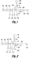
- Figure 1 shows a first embodiment, generally depicted at 100, of an interferometer for measuring the optical amplitude, phase and frequency of an optical signal.
- the incoming light from a light source (not shown) is preferably amplified in an optical amplifier 101, and transmitted to the optical filter 102.
- the filter 102 filters the out of band Amplified Spontaneous Emission noise (ASE) of the amplifier 101.
- the light then enters into an optical circulator 103 which is connected to a 3 x 3 optical coupler 104.
- a portion of the light is directed to the photodetector 112 to monitor the light intensity of the input light.
- the other portions of light are directed along first and second optical paths 105 and 106, with a path length difference (109) between the two paths.
- the path length difference therefore introduces a delay into one arm 105 of the interferometer, such that the light that is reflected back for interference at any one time in that arm 105 is from a point closer along the fiber than the light available for interference in the other arm 106.
- This difference in length between the arms of the interferometer relates to (but is not quite equal to) the spatial resolution obtained, and is referred to herein as the gauge length.
- Faraday-rotator mirrors (FRMs) 107 and 108 at the ends of the interferometer arms reflect the light back through the first and second paths 105 and 106, respectively.
- the Faraday rotator mirrors provide self-polarisation compensation along optical paths 105 and 106 such that the two portions of light reflected from the FRMs efficiently interfere at each of the 3x3 coupler 104 ports.
- the optical coupler 104 introduces relative phase shifts of 0 degrees, +120 degrees and -120 degrees to the interference signal, such that first, second and third interference signal components are produced, each at a different relative phase.
- First and second interference signal components are directed by the optical coupler 104 to photodetectors 113 and 114, which measure the intensity of the respective interference signal components.
- the circulator 103 provides an efficient path for the input light and the returning (third) interference signal component through the same port of the coupler 104.
- the interference signal component incident on the optical circulator 103 is directed towards photodetector 115 to measure the intensity of the interference signal component.
- the outputs of the photodetectors 113, 114 and 115 are combined to measure the relative phase of the incoming light, as described in more detail below with reference to Figures 7 and 9 .
- frequency shifters 110 and 111 and/or optical modulator 109 may be used along the paths 105 and 106 for heterodyne signal processing.
- the frequency shift of 110 and 111 may be alternated from f1, f2 to f2, f1 respectively to reduce any frequency-dependent effect between the two portions of the light propagating through optical paths 105 and 106.
- the above-described embodiment provides an apparatus suitable for fast quantitative measurement of perturbation of optical fields, and in particular can be used for distributed and multiplexed sensors with high sensitivity and fast response times to meet requirements of applications such as acoustic sensing.
- Figure 7 shows an application of the interferometer of Figure 1 to the distributed sensing of an optical signal from an optical system 700. It will be apparent that although the application is described in the context of distributed sensing, it could also be used for point sensing, for example by receiving reflected light from one or more point sensors coupled to the optical fibre.
- light emitted by a laser 701 is modulated by a pulse signal 702.
- An optical amplifier 705 is used to boost the pulsed laser light, and this is followed by a band-pass filter 706 to filter out the ASE noise of the amplifier.
- the optical signal is then sent to an optical circulator 707.
- An additional optical filter 708 may be used at one port of the circulator 707.
- the light is sent to sensing fibre 712, which is for example a single mode fibre or a multimode fibre deployed in an environment in which acoustic perturbations are desired to be monitored.
- a length of the fibre may be isolated and used as a reference section 710, for example in a "quiet" location.
- the reference section 710 may be formed between reflectors or a combination of beam splitters and reflectors 709 and 711.
- the reflected and the backscattered light generated along the sensing fibre 712 is directed through the circulator 707 and into the interferometer 713.
- the detailed operation of the interferometer 713 is described earlier with reference to Fig 1 .
- the light is converted to electrical signals using fast low-noise photodetectors 112, 113, 114 and 115.
- the electrical signals are digitised and then the relative optical phase modulation along the reference fibre 710 and the sensing fibre 712 is computed using a fast processor unit 714 (as will be described below).
- the processor unit is time synchronised with the pulse signal 702.
- the path length difference (109) between path 105 and path 106 defines the spatial resolution.
- the photodetector outputs may be digitised for multiple samples over a given spatial resolution. The multiple samples are combined to improve the signal visibility and sensitivity by a weighted averaging algorithm combining the photodetector outputs.
- the optical modulator 703 may be driven by a microwave frequency of around 10-40 GHz to generate optical carrier modulation sidebands.
- the optical filter 708 can be used to select the modulation sidebands which are shifted relative to the carrier. By changing the modulation frequency it is possible to rapidly modulate the selected optical frequency.
- Figure 9 schematically represents a method 1100 by which the optical phase angle is determined from the outputs of the photodetectors 113, 114, 115.
- the path length difference between path 105 and path 106 defines the spatial resolution of the system.
- the photodetector outputs may be digitised for multiple samples over a given spatial resolution, i.e. the intensity values are oversampled. The multiple samples are combined to improve the signal visibility and sensitivity by a weighted averaging algorithm combining the photo-detector outputs.
- the three intensity measurements I 1 , I 2 , I 3 , from the photodetectors 113, 114, 115 are combined at step 1 102 to calculate the relative phase and amplitude of the reflected or backscattered light from the sensing fibre.
- the relative phase is calculated (step 1104) at each sampling point, and the method employs oversampling such that more data points are available than are needed for the required spatial resolution of the system.
- a visibility factor V is calculated at step 1106 from the three intensity measurements I 1 , I 2 , I 3 , from the photodetectors 113, 114, 115, according to equation (1), for each pulse.
- V I 1 ⁇ I 2 2 + I 2 ⁇ I 3 2 + I 3 ⁇ I 1 2
- the intensity values at respective phase shifts are similar, and therefore the value of V is low.
- Characterising the sampling point according the V allows a weighted average of the phase angle to be determined (step 1108), weighted towards the sampling points with good visibility. This methodology improves the quality of the phase angle data 1110.
- the visibility factor V may also be used to adjust (step 1112) the timing of the digital sampling of the light for the maximum signal sensitivity positions.
- Such embodiments include a digitiser with dynamically varying clock cycles, (which may be referred to herein as "iclock").
- the dynamically varying clock may be used to adjust the timing of the digitised samples at the photodetector outputs for the position of maximum signal sensitivity and or shifted away from positions where light signal fading occurs.
- the phase angle data is sensitive to acoustic perturbations experienced by the sensing fibre. As the acoustic wave passes through the optical fibre, it causes the glass structure to contract and expand. This varies the optical path length between the backscattered light reflected from two locations in the fibre (i.e. the light propagating down the two paths in the interferometer), which is measured in the interferometer as a relative phase change. In this way, the optical phase angle data can be processed at 1114 to measure the acoustic signal at the point at which the light is generated.
- the data processing method 1100 is performed utilising a dedicated processor such as a Field Programmable Gate Array.
- Each photodetector has electrical offset of the photodetectors, i.e. the voltage output of the photodetector when no light is incident on the photodetector (which may be referred to as a "zero-light level" offset.
- a first step switching off the incoming light from the optical fibre and the optical amplifier 101.
- the optical amplifier 101 acts as an efficient attenuator, allowing no significant light to reach the photodetectors.
- the outputs of the photodetectors are measured (step 1204) in this condition to determine the electrical offset, which forms a base level for the calibration.
- the relative gains of the photodetectors can be measured, at step 1208, after switching on the optical amplifier 101 while the input light is switched off (step 1206).
- the in-band spontaneous emission i.e. the Amplified Spontaneous Emission which falls within the band of the bandpass filter 102
- This signal can also be used to measure the signal offset, which is caused by the in-band spontaneous emission.
- the optical amplifier which is a component of the interferometer, is used as in incoherent light source without a requirement for an auxiliary source.
- the incoherence of the source is necessary to avoid interference effects at the photodetectors, i.e. the coherence length of the light should be shorter than the optical path length of the interferometer.
- the frequency band of the source is preferable for the frequency band of the source to be close to, or centred around, the frequency of light from the light source.
- the bandpass filter 102 is therefore selected to filter out light with frequencies outside of the desired bandwidth from the Amplified Spontaneous Emission.
- the above- described method can be used between optical pulses from the light source, to effectively calibrate the system during use, before each (or selected) pulses from the light source with substantively no interruption to the measurement process.
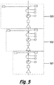
- Figure 2 shows another embodiment, generally depicted at 200, of a novel interferometer similar to that shown in Figure 1 but with an additional Faraday-rotator mirror 201 instead of photodetector 112.
- Like components are indicated by like reference numerals.
- the interference between different paths which may have different path length, can be separated at the three beat frequencies f 1 , f2 and (f 2 -f 1 ).
- the arrangement of this embodiment has the advantage of providing additional flexibility in operation, for example the different heterodyne frequencies can provide different modes of operation to generate measurements at different spatial resolutions.
- Figure 3 shows another embodiment of a novel interferometer, generally depicted at 300, similar to the arrangement of Figure 1 , with like components indicated by like reference numerals.
- this embodiment uses a 4x4 coupler 314 and an additional optical path 301, frequency shifter 304, phase modulator 303, Faraday-rotator mirror 302 and additional photo-detector 308.
- the interference between different paths which may have different path length differences, can be separated at the three beat frequencies (f 2 -f 1 ), (f 3 -f 2 ) and (f 3 -f 1 ).
- the Faraday-rotator mirror 302 may be replaced by an isolator or a fibre matched end so that no light is reflected through path 301, so only allowing interference between path 105 and 106.
- the 4 x 4 optical coupler of this arrangement generates four interference signal components at relative phase shifts of -90 degrees, 0 degrees, 90 degrees, 180 degrees.
- Fig 4 shows another embodiment of the interferometer.
- an additional path is introduced in the interferometer by inserting a Faraday-rotator mirror 402 instead of the photo-detector 112.
- optical switches may be used to change and/or select different combinations of optical path lengths through the interferometer. This facilitates switching between different spatial resolutions measurements (corresponding to the selected path length differences in the optical path lengths).
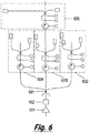
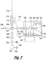
- Figures 5 and 6 show examples of interferometer systems 500, 600 arranged for used in cascaded or star configurations to allow the measuring of the relative optical phase for different path length differences.
- three interferometers 501, 502, 503 having different path length differences (and therefore different spatial resolutions) are combined in series.
- four interferometers 602, 603, 604 and 605 having different path length differences (and therefore different spatial resolutions) are combined with interferometers 602, 603, 604 in parallel, and interferometers 603 and 605 in series.
- 601 is a 3 x 3 coupler, used to split the light between the interferometers.
- Arrangement 600 can also be combined with wavelength division multiplexing components to provide parallel outputs for different optical wavelengths.
- Embodiments described above relate to apparatus and methods for fast quantitative measurement of acoustic perturbations of optical fields transmitted, reflected and or scattered along a length of an optical fibre.
- Embodiments of the invention can be applied or implemented in other ways, for example to monitor an optical signal generated by a laser, and/or to monitor the performance of a heterodyne signal generator, and to generate optical pulses for transmission into an optical signal. An example is described with reference to Figure 8 .
- Figure 8 shows a system, generally depicted at 800, comprising an interferometer 801 in accordance with an embodiment of the invention, used to generate two optical pulses with one frequency-shifted relative to the other.
- the interferometer receives an input pulse from a laser 701, via optical circulator 103.
- a 3 x 3 optical coupler 104 directs a component of the input pulse to a photodetector, and components to the arms of the interferometer.
- One of the arms includes a frequency shifter 1 10 and an RF signal 805.
- the interference between the two pulses is monitored by a demodulator 802.
- the light reflected by Faraday-rotator mirrors 107 and 108 is combined at the coupler 809 using a delay 803 to match the path length of the interferometer, so that the frequency shifted pulse and the input pulse are superimposed.
- the coupler 809 introduces relative phase shifts to the interference signal, and interferometer therefore monitors three heterodyne frequency signal components at relative phase shifts.
- the optical circulator 103 passes the two pulses into the sensing fibre.
- the reflected and backscattered light is not detected by an interferometer according to the invention. Rather, the reflected and backscattered light is passed through an optical amplifier 804 and an optical filter 806 and are then sent to a fast, low-noise photodetector 807.
- the electrical signal is split and then down-converted to baseband signals by mixing the RF signal 805 at different phase angles, in a manner known in the art.
- the electrical signals are digitised and the relative optical phase modulation at each section of the fibre is computed by combining the digitised signals using a fast processor 808.
- Fig 11 shows another embodiment of apparatus for point as well as distributed sensors.
- the modulation frequency 704 of the optical modulator 703 is switched from f1 to f2 within the optical pulse modulation envelope.
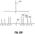
- the optical filter 708 selects two modulation frequency sidebands 1202/1203 and 1204/1205 generated by the optical modulator as indicated in Figure 12 .
- the frequency shift between first order sidebands 1202 and 1203 is proportional to the frequency modulation difference (f2-f1) whereas the frequency shift between 2 nd order sidebands 1204 and 1205 is proportional to 2(f2-f1). Therefore, the photo-detector output 806 generates two beat signals, one of which is centred at (f2-f1) and the other at 2(f2-f1).
- the demodulator 901 the relative optical phase of the beat signals can be measured independently. The two independent measurements can be combined to improve the signal visibility, the sensitivity and the dynamic range along the sensing fibre.
- Figure 12A shows the modulation spectrum of the light and the selection of the sidebands referred to above.
- Figure 12B shows the original laser pulse 1206 with pulse width of T at frequency f o which is modulated at frequency f1, f2 and f3 during a period T1, T2 and T3, respectively.
- the delay between T1, T2 and T3 can also be varied.
- One or more modulation sidebands is/ are selected with the optical filter 708 to generated a frequency shifted optical pulses that are sent into the fibre.
- the reflected and/ or backscatter signals (709, 710, 711 and 712) from the fibre from is directed to a photodetector receive via a circulator 707.
- the reflected and or backscatter light from different pulses mix together at the photodetector output to generate heterodyne signals such (f2-f1), (f3-f1), (f3-f2), 2(f2- f1), 2(f3-f1) and 2(f3-f2).
- Other heterodyne signals are also generated but (2f2-f1), (2f3- f1), (2f1-f2), (2f1-f3), (2f3-f1) and (2f3-f2) are also generated at much higher frequencies.
- the heterodyne signal are converted down to base band in-phase and quadrature signals.
- the in-phase and quadrature signals are digitise by a fast analogue to digital convertors and the phase angle is computed using fast digital signal processor.
- embodiments of the present invention correspond to those already published in our previous International patent application no WO 2010/136810 , and relate to various versions of an optical fiber distributed acoustic sensor that form the basis for embodiments of the present invention.
- embodiments of the present invention make use of any of the previously published arrangements with a modified fiber that includes specific reflection points along its length, spaced in dependence on the intended spatial resolution (strictly speaking to the gauge length) of the DAS, and also optionally with some additional signal processing enhancements, to significantly increase the sensitivity of the overall optical fiber sensing system thus obtained. Further details are given next.
- the performance of a fiber optic distributed acoustic sensor is limited by the system's acoustic signal to noise ratio (SNR). Improving the acoustic SNR can lead to, for example, quantification of flow, seismic and leak signals which are otherwise unmeasurable.
- the acoustic SNR of a DAS in turn depends upon the DAS optical SNR, which is the relationship of the magnitude of the optical signal and the associated detection noise.
- the optical SNR, and so the acoustic SNR is optimised by maximising the amount of optical signal returning from the optical fibre.
- the returning optical signal can be maximised using a number of techniques, including using a shorter wavelength source light (shorter wavelengths scatter more) and using a fibre with a large scattering coefficient or a large capture angle.
- a technique using introduced reflection points at pre-determined positions in the fibre should have the functionality of partially-reflective mirrors - ideally they should reflect a small amount of light (typically less than 0.1%) across a relatively large bandwidth (e.g. of the order of >2 nm) and transmit the remainder. Even with such a small reflectivity, the amplitude of reflected light will still be more than an order of magnitude larger than that of the naturally backscattered light over the same spatial interval.
- the use of reflectors therefore has an advantage over other techniques, such as using a higher scattering coefficient, in that all of the light lost from the transmission is reflected back towards the DAS rather than scattered in all directions.
- reflection points give another significant benefit to the DAS noise characteristics. This is because, when using standard fibres, a DAS is typically subject to 1/f noise, meaning that the acoustic noise for low frequencies (particularly below 10Hz) is significantly higher than the noise at higher frequencies. The existence of 1/f noise is fundamental to the random nature of backscattering characteristics and dominates the DAS performance for low frequency measurements, which constitute a major part of the DAS applications. When using reflection points, however, reflection characteristics are fixed, rather than random, and this has the effect of reducing the 1/f noise to an unmeasurable level.
- the controlled scattering also results in a uniform noise floor, both spatially and temporally, whereas random scattering inherent produces a noise floor characteristic which typically varies rapidly in distance and slowly in time.
- the fixed reflection characteristics result in a more stable measured acoustic amplitude than is achieved using backscattering.
- each reflection point along the fiber would be a weak mirror -that is a reflection point would reflect all wavelengths of light equally, with a constant reflection coefficient.
- the reflection coefficient would be around 0.01% (which is around 100x more light than is backscattered per metre of fibre), meaning that each mirror reflects 0.01% and transmits 99.99% of the incident light.
- a range of reflection coefficients would be acceptable, for example ranging for example from 0.002% to 0.1%, depending on design considerations.
- a smaller reflection coefficient will lead to less light reflected, and hence a smaller performance improvement, but will allow for greater theoretical range, whereas a higher reflection coefficient will reflect more light and hence provide greater signal to noise ratio, but may impact the sensing range along the fiber, particularly for finer spatial resolutions where the reflection points are closer together.
- a reflection coefficient of 0.01% is used, then due to the low loss at each reflection point, it is practical to insert many 100s of such weak mirrors into the fibre without introducing significant optical losses. For example, 1000 reflection points would introduce an excess loss of just 0.4dB (equivalent to the loss of 2km of standard optical fibre).
- the reflection points are typically spaced at the same distance as the spatial resolution ("gauge length") of the DAS. This means that, if the DAS spatial sensing resolution is 10m, 1000 reflection points can be used to make up a total sensing length of 10km.
- the DAS needs no modification to make it compatible with the fibre containing the reflection points - conceptually, the DAS treats the new fibre the same as standard fibre (albeit with a higher scattering coefficient).
- the DAS signal processing can be optimised for use with this fibre by making use of the fact that now all sensing positions between each pair of reflection points measure the same signal. This means, for example, we can measure many positions between reflection points and then average the signals from these positions to improve the SNR.
- the increased signal to noise ratio can be used to significantly improve the spatial resolution of the DAS while still maintaining an acceptable noise performance.
- a DAS using backscatter requires a gauge length of around 1m to achieve an acceptable SNR for most applications, using reflectors
- an acceptable SNR can be achieved with a gauge length of around 5cm.
- Such an improvement in spatial resolution allows the accurate measurement of ultrasonic signals and, for example, the tracking of features associated with short length scales, such as eddies in pipes. It may be necessary to use a phase correlation arrangement with a narrow detection bandwidth to achieve sufficient signal-to-noise performance.
- There can also be advantages in long range applications such as leak detection, pipelines and subsea.
- Another feature is to measure very small temperature variations along a section of a pipe caused by fluid flow down to less than m°K and up to few Hertz.
- the high resolution temperature measurement can be used to measure the fluid flow by observing the propagation of the exchange of the turbulent thermal energy.
- the DAS configuration may be identical for measuring on either standard fibre or fibres with reflection points it is possible to perform a hybrid measurement, where the DAS simultaneously measures on both fibre types.
- the reflection points could be positioned at strategic positions where more sensitivity is required (for example to measure flow) whereas the rest of the fibre, which is unmodified, is used for measurements, such as seismic, where more coverage and less sensitivity is required.
- FBG Fibre Bragg Grating
- a FBG is usually designed as either an optical filter or as a sensing element where the peak reflection wavelength of the grating is used to determine the grating spacing and hence the strain or temperature of the FBG.
- FBGs can be written into an optical fiber using femtosecond laser writing processes.
- FBGs can now be written directly into an optical fibre as the fibre is drawn, and before the fibre is coated, making it commercially and technically practicable to produce a fibre with 1000s of FBGs.
- FBGs can be embedded into an optical fiber by changing its refractive index using femtosecond laser writing processes or written by UV laser during fiber drawing.
- FBGs are generally designed to maximise peak reflection, and to selectively reflect a particular wavelength (which may change with temperature or strain).
- each FBG in this example is around 1mm in length, with a separation of 10mm between FBGs, meaning the total length of each reflection point is around 45mm.
- the overall reflection bandwidth is around +/-2nm. It was found though that this configuration is not ideal. This is because the overlap (in wavelength) of the gratings required to ensure we get reflection over the whole bandwidth leads to interference between the FBGs at each reflection point when the DAS laser is in the overlapping range (see Figure 14 ). For this reason, in other embodiments we propose to change the FBG design to either of:
- reflection points introduces crosstalk caused by multiple reflections between the reflection points. These multiple paths will lead to an ambiguity in the location of a proportion of the optical signal (crosstalk).
- crosstalk Our modelling suggests that this will not be a major issue for our target applications, provided the sum of the reflectivities of the reflection points does not exceed -10%. For example, this condition allows the equivalent of 1000 reflection points each with a reflectivity of 0.01%.
- Figure 15 illustrates the use of an angled grating 1510 extending across the fiber.
- the grating includes a right-angled elbow section 1530, that is arranged such that it receives light passing along the fiber from a first direction, and reflects it back in the opposite direction, via two substantially 90 degree reflections from the grating. That is, the light from the first direction is incident on the "inside" edge of the elbow, such that it is then reflected back in the direction it came.
- Another technique to reduce crosstalk is to increase the reflectivity over distance. This works because the nearer markers contribute most to the crosstalk.
- Such an arrangement also has the advantage that the reflectivity profile can be chosen to compensate for loss in the fibre, so giving an equal SNR along the fibre length.
- Figure 16 illustrates an alternative arrangement where a coupler component is used to couple a small proportion of the light into another fiber, that is then coupled to a mirror.
- the mirror is fully 100% reflective, and the coupling coefficient of the coupler is controlled so as to couple only a small amount (e.g. 0.01%, or some such value, as discussed above) of the incident light towards the mirror, so that the same overall weak reflection that is desired as described above is obtained.
- Figures 17 and 18 illustrate the concept of embodiments of the invention numerically.
- Figure 17A a typical DAS scenario of the prior art is considered.
- Figure 17B a typical time domain interferometric multiplexed setup, such as shown in Figure 17B (and taken from Kersey et al. Cross talk in a fiber-optic sensor array with ring reflectors, Optics Letters, Vol 14, No. 1 Jan 1 1989 ) up to third of photons may be used for measurement purposes.
- the reflectors are fiber Bragg gratings (FBGs), as discussed previously.
- FBGs fiber Bragg gratings
- the total reflection along the whole length of fiber should preferably be less than 10% ( RN ⁇ 0.1) and with such constraints it is possible to cover 3 km of fiber by gratings with a 10 m period.
- Such a system can then deliver a shot noise more than 10 times better than current DAS systems, as discussed earlier.
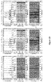
- Figure 19 illustrates the results of testing the concept on a fiber model with 4 gratings with reflectivity 0.001% separated by 10 m which are clearly visible under short pulse (10 ns) illumination (see Fig. 19A ).
- a 10 m resolution DAS was used we can see also additional reflections delayed by the gauge length (the path length difference between the arms 105 and 106 of the interferometer in the DAS, and which sets the initial spatial resolution of the DAS), so interference was inside 3 low contrast Fabry-Perot interferometers.
- An acoustic signal was applied for 2 of them only, as visible on the waterfall graphs (the middle graphs) measured with 1 m sampling.
- the acoustic signal is applied repeatedly every 30 time samples or so at a distance of between 50m and 70m along the fiber.
- a longer optical pulse (70 ns) can generate more signal as is clear from Fig. 19B .
- the red horizontal line in the spectrum corresponds to the acoustic modulation zone (i.e. where the acoustic signal was applied); optical crosstalk to the third interferometer located between 70m and 80m is negligible.
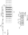
- a fiber with reflectors which may, for example, be the gratings described in the above embodiments, spaced every 10m. These are shown as reflectors 202, 204, and 206 on Figure 20 .
- the reflectors are regularly spaced in at least one portion of the fiber where it is desired to undertake dual-resolution sensing. Of course, in some embodiments this may be along the whole length of the fiber. In other embodiments, different sections of fiber may have reflectors spaced at respective different spacings, such that different spatial resolutions are obtained from the respective different sections.
- the DAS system controls the DAS system to produce optical pulses to be sent into the fiber such that the pulse width is less than the reflector spacing, but where the gauge length of the DAS system (i.e. the path length difference 109 between the arms 105 and 107 of the DAS sensing interferometer 713) is greater than the reflector spacing then as a pulse travels along the fiber there will be an instance during which the respective reflected light from the pulse in the arms 105 and 107 of the interferometer is from consecutive reflectors, in which case during this time a sensing resolution equal to the reflector spacing is obtained.
- the gauge length of the DAS system i.e. the path length difference 109 between the arms 105 and 107 of the DAS sensing interferometer 713
- a pair of pulses are shown travelling down the fiber, the fiber being provided with reflectors 202, 202, and 206 spaced 10 m apart.
- the pair of pulses described here correspond to an actual pulse 210 transmitted along the fiber from the DAS, and, in the case of receiving interferometer arrangement, a virtual delayed pulse 212, delayed by the gauge length of the interferometer.
- the virtual delayed pulse 212 never actual travels along the fiber, but is instead generated as a delayed version of the reflections of the actual pulse 210 in the arm 105 of the interferometer 713, as described above.
- the virtual delayed pulse can equally be thought of as virtually travelling along behind the actual pulse along the fiber, separated therefrom by the gauge length, and in the following this model is adopted.
- the delayed pulse is only ever in existence in the form of reflected light from along the fiber from the actual pulse when delayed in arm 105 of the interferometer, and hence pulse 212 travelling along the fiber is a virtual pulse provided for the sake of descriptive convenience only.
- the pulses have respective lengths of 7.5m, and the pulse separation (corresponding to the gauge length) i.e. from falling (or rising) edge to falling (or rising) edge is 15m; hence there is a 7.5m gap between the falling edge of the leading pulse and the rising edge of the following virtual pulse.
- the leading actual pulse 210 is positioned so that it is still passing over reflector 204, such that some of the pulse is reflected back along the fiber as the pulse passes over the reflector.
- the trailing virtual pulse 212 is just incident on reflector 202, and hence is just about to start reflecting some of its light back along the fiber (in reality of course, as noted above the light considered to be reflected from the virtual pulse is actually earlier reflected light from the actual pulse, subject to the gauge length delay in the interferometer).
- a small portion of actual pulse 210 is reflected from reflector 204 whilst a small portion of virtual pulse 212 is reflected from reflector 202.
- This reflected light from both pulses then travels back along the fiber where it can then be processed in the DAS, for example by being interfered together in the DAS interferometer, so as to allow a DAS signal with resolution equal to the distance between the reflectors 202 and 204 i.e. one reflector spacing, in this case 10m to be found.
- Trailing virtual pulse 212 is still "passing" over reflector 202 at point B and hence some light is reflected therefrom, but because there is no light from actual pulse 210 to interfere with in the DAS, no signal is produce at this time. This situation continues until time C, at which point leading actual pulse 210 then starts to pass over the next reflector 206. At this time, trailing virtual pulse 212 is still "passing" over reflector 202, located two reflector spacings away from reflector 206.
- This 20m sensing resolution is then obtained from time C to time D, during which the leading actual pulse 210 passes over reflector 206, and the trailing virtual pulse 212 passes over reflector 202.
- time C to D therefore, a sensing resolution output of 20m, or twice the reflector spacing, is obtained.
- the trailing virtual pulse 212 finishes passing over reflector 202, and hence from time D no signal is obtained, until trailing virtual pulse 212 is incident on the next reflector 204 (not shown).
- the leading actual pulse 210 would still be passing over reflector 206, and hence the same situation as shown at time A would pertain, except for the next pair of reflectors along the fiber i.e. 204 and 206, rather than 202 and 204.
- the process therefore repeats, for each successive pair of reflectors along the fiber.
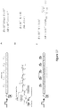
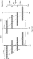
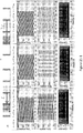
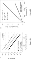
- Figure 21 illustrates the dual sensitivity arrangement again, together with some simulated results.
- the principle is shown at Figure 21A, where an optical pulse and its delayed-over- L0 virtual echo travel along the fiber they cover consequently one or two zones between reflectors separated by the distance L ⁇ 2 / 3L0 .
- the sensitivity base of the DAS is changing along the fiber from L to 2L and back again, as the pulses travel therealong.
- L0 15m, with 75 ns pulse ( ⁇ 7.5m pulsewidth) and 1m sampling for different acoustic wavelengths. If the wavelength ( ⁇ ) is 60m (so it is significantly longer than L and L0, see on Fig. 21 B) then the DAS output pattern (Fig. 21C) follows it, but some space zones have twice the amplitude, see also a spectrum shown on Fig. 21D.
- FIG. 21 H-J The last pictures demonstrate a DAS output for where the wavelength is between the dual sensitivities i.e. between 10m and 20m. Generally, therefore, where L ⁇ ⁇ ⁇ 2L.
- SNR signal to noise ratio
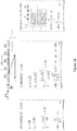
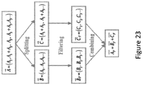
- One algorithm for such transformation is presented on Figure 23 .
- a 2D vector of channels A is split into zones each corresponding to L and 2L (to give B and C ), then each is filtered (including deconvolution if necessary) separately to produce Bf and Cf correspondently.
- the illuminated reflectors i.e. those which a pulse is presently passing over produce a reflected signal and so affect the output signal, and hence acoustic antenna length can then be chosen from a range of lengths corresponding to different multiples of the distance between the reflectors to optimise the output. That is, the gauge length can be chosen to select how many reflectors are between the pulse pairs, and hence the spatial resolution of the DAS may be controlled using a fibre with a fixed set of reflection points.
- this is performed by selecting the pulse width and the virtual pulse separation (gauge length) characteristics, such that the desired number of reflectors are encompassed by the sum of the pulse width and the pulse separation to give the resolution required.
- the pulse width and the virtual pulse separation (gauge length) characteristics such that the desired number of reflectors are encompassed by the sum of the pulse width and the pulse separation to give the resolution required.
- Figure 24 illustrates one modification that may be made to any of the above described embodiments,
- the reflectors 1320 need not be provided all the way along the fiber 1310, but instead can be provided only in specific sections, with further sections of fiber then in between in which no reflectors are provided.
- One or plural sections of fibers may be provided each having multiple reflectors provided therein distributed therealong, These sections may then be interspersed between conventional lengths of fibers having no reflectors therein.
- the advantage of such an arrangement is that the range of the optical fiber distributed sensing system can be increased, by only providing the reflectors in those portions of the fiber that are located where sensing is actually desired.
- optical fibers in between those locations which are not provided with reflectors then effectively become relatively lower-loss transmission portions for transporting the optical pulses between the sensing portions provided with the reflectors.
- the optical fiber can be characterised as having pulse transmission portions where no reflectors are provided, in between one or more sensing portions in which the reflectors are distributed therealong.
- Figure 25 illustrates a further variant of the above.
- three sensing portions 2510, 2520, and 2530 of fiber are provided, each provided with plural reflectors 1320.
- the sensing portions of fiber are dispersed at different longitudinal positions along the whole fiber, and are connected by transmission portions of fiber within which no reflectors are provided, and hence which are relatively low loss for carrying the optical pulses from sensing portion to sensing portion.
- each sensing portion 2510, 2520, and 2530 has reflectors that reflect different, substantially non-overlapping, wavelengths of light.
- the reflectors in the first sensing portion 2510 reflect light around a ⁇ m
- those of the second sensing portion 2520 reflect light around b ⁇ m
- those of the third sensing portion 2530 reflect light around c ⁇ m.
- At wavelengths that the reflectors don't reflect the incident light is transmitted by the reflectors with substantially no additional loss.
- the optical fiber distributed sensor system is able to provide spatial selectivity in terms of which set of reflectors at which spatial location it wants to receive reflections from (and thereby enable sensing at that location), by varying the wavelengths of the transmitted pulses to match the reflector wavelengths of the set of reflectors that are to be selected.
- varying the wavelengths provides the spatial selectivity of where the sensing system will sense, specifically which set of reflectors will provide reflections from which sensing can then be undertaken.
- non-selected reflectors do not reflect substantially at the wavelengths of the pulses being transmitted along the fiber for the selected set of reflectors, losses from unwanted reflections are kept to a minimum, and the sensor range is increased.
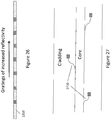
- Figure 26 illustrates a further modification that may be made to provide further embodiments of the invention.
- the fiber 1310 is again connected to an optical fiber distributed sensor system (not shown), and is provided in at least one sensing portion thereof (or alternatively, all along its length) with reflector portions the reflectivity of which are different along the length of the fiber.
- the reflectivity of the reflector portions increases along the length of the fiber with distance from the optical pulse source in the optical fiber sensing system, such that reflector portions further away from the source have greater reflectivity than those nearer the source.
- the reflectivity in some embodiments increases deterministically in accordance with a mathematical function of the distance along the fiber.
- the mathematical function may be a monotonic function relating distance along the fiber to reflectivity.
- One of the primary motivations for altering the reflectivity of the reflectors along the fiber is to account for crosstalk between the reflectors.
- Crosstalk results from unwanted light, which has undergone reflections off multiple reflectors, returning coincidently with the signal of interest, which undergoes one reflection only.
- the wanted optical power strength will be proportional to R (the reflectivity of a single reflector)
- the crosstalk signal (if we ignore optical losses and assume equal reflectivity for all reflectors) will be approximately proportional to NxR 3 , where N is the number of optical paths that allow the crosstalk light to arrive at the detector coincidently with the signal light.
- the crosstalk can be minimised by reducing both N and R; however the useful optical signal is maximised by increasing R and the spatial resolution is optimised by increasing the number of reflectors, and hence N.
- N the number of reflectors
- N and hence the amount of crosstalk experienced by the signal, increases along the fibre length. For example, there is no crosstalk for the first pair of reflectors as there is no valid crosstalk optical path which allows the crosstalk light to arrive coincidently with the signal light. Similarly, the contribution of crosstalk from acoustic signal generated towards the beginning of the fibre is larger than the contribution of the same signal level towards the end of the fibre. This is because there are many more valid crosstalk optical paths which encompass reflectors towards the beginning of the fibre than towards the end. For example, a reflection off the last reflector in the fibre has no valid path where it can contribute to crosstalk whereas a reflection off the first reflector can contribute to crosstalk by reflecting light from any other reflectors.
- an elegant approach to optimise performance in response to this property is to vary the reflectivity of the reflectors along the fibre length.
- the nearer reflectors which contribute more to crosstalk
- the far reflectors are chosen to have a lower reflectivity than the far reflectors.
- This type of reflectivity profile is also beneficial in that the reflectivity can be tuned to also compensate for the optical losses in the fibre (and through any connectors/splices or other losses along the optical path) and so equalise, or otherwise tune, the signal to noise performance, as well as tune crosstalk, along the fibre.
- the crosstalk contribution from regions along the optical path with a large acoustic signal of low importance can be negated by choosing a low reflectivity reflectors (or no reflectors) along that section.
- the signal of interest is towards the far end of the installation (for example the perforated section at the bottom of an oil well).
- the crosstalk contribution from the near end of the installation can be minimised by deploying the fibre in a "U" arrangement where the reflectors may be positioned in the far end of the leading fibre and may be then continued to the top of the return fiber.
- the laser light is launched down the fibre leg with no reflectors, such that the first reflector encountered is at the bottom of the well. This ensures a good crosstalk behaviour as the region of interest at the bottom of the well is positioned first in the optical path, and so encounters minimal crosstalk.
- the loud section, at the top of the well is positioned at the end of the optical fibre and so does not contribute crosstalk to the majority of the optical path, including the particular region of interest.
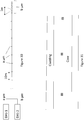
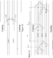
- Figure 27 illustrates one way of forming the reflector portions in the cladding of the fiber, rather than in the core.
- the gratings are instead formed in the cladding layer, and coupled into the core via waveguides 2710.
- light propagating along the core couples into the waveguides 2710 and is fed to the gratings 1320, from where it is then reflected back along the fiber.
- Figure 29 illustrates a further embodiment, related to adapting the pulse repetition rate of the DAS.
- the DAS operates by sending an optical pulse along the fiber, and then measuring reflections from reflector portions positioned along the fiber, as described above.
- Figure 29 shows in simplified form such an arrangement, where a single set of reflectors is provided at a single sensing portion of the fiber, with the remainder of the fiber between the sensing portion and the DAS being substantially free of sensors.
- the pulse transit time that is important is the transit time for the pulse to transit the sensing portion only, plus the transit time for backscatter from along the length of the sensing portion. If the pulse transit time is ⁇ r, then allowing time for the backscatter the minimum pulse spacing is 2 ⁇ r, plus typically some sort of small guard time g in between pulses, which may be say 10% of ⁇ r.
- the pulse repetition rate can then be increased to 1/(2 ⁇ r + g), which, depending on the relative length of the sensing portion compared to the whole fiber length, will be significantly higher than the pulse repetition rate required to provide whole length of fiber sensing. As a consequence, the sampling frequency of the DAS can be increased, so as to allow the DAS to detect higher frequencies.
- the pulse repetition rate of the DAS can be increased by a factor equal to the ratio of the transmission portion of the fiber to the sensing portion. For example, therefore, if the sensing portion is provided only along one quarter of the length of the fiber then the pulse repetition rate may be increased by a reciprocal amount i.e. by a factor of four.
- Figure 30 shows a further arrangement where two DAS systems are multiplexed on to a single fiber, and the fiber is provided with reflectors in two distinguishable sensing portions, being a first portion where the spacing between the reflectors is greater than the spacing between reflectors in a second portion.
- the reflectors in the first portion are arranged to reflect a first wavelength a ⁇ m
- the reflectors in the second portion are arranged to reflect a second wavelength, b ⁇ m.
- the reflectors in the first portion are spaced by 10m
- the reflectors in the second portion are spaced more closely together to give a higher spatial sensing resolution of 1m.
- DAS1 and DAS2 are provided both multiplexed onto the single sensing fiber.
- DAS1 operates at the first wavelength a ⁇ m
- DAS2 operates at the second wavelength b ⁇ m.
- Providing two DAS systems multiplexed on to the same fiber allows for simultaneous multi-frequency operation, which in this case provides for simultaneous multi-spatial resolution operation, due to the different reflector spacings in the two sensing portions. Hence, with such an arrangement multiple sensing resolutions can be obtained simultaneously from different parts of the same fiber.
- the different wavelength reflectors are instead provided along the length of the fiber in overlapping portions, but at the same respective spacings. Because the reflectors are arranged to reflect at different wavelengths, however, being the first and second wavelengths of the DAS1 and DAS2 systems respectively, there is no interference of the respective operations of the two DAS systems, and multi-spatial resolution sensing at the two resolutions is then obtained along the length of the same fiber.
- Figure 31 shows a multi-mode fiber embodiment, where the reflector gratings are provided within the multi-mode core, as shown.
- multi-mode fiber cores are much wider than single mode fiber cores, but as the DAS systems are internally single mode systems it is sufficient to locate reflector gratings in the center of the core to reflect the lowest order mode, which is the mode that will typically be coupled into the DAS.
- Figure 28 illustrates an alternative version, where instead of gratings, weakly reflecting right-angled reflection structures are formed in the core instead. The operation of such is the same as if gratings were being used, but with the difference that the reflection structures are truly broadband, and will reflect some of the incident light of any wavelength propagating in the fiber.
- Figures 32 and 33 show multi-core embodiments of the invention.
- Using multi-core fibers opens up the concept of having "forward" channels for the forward pulse launched from the DAS or DTS system and "return" channels into which the forward light can be reflected for return to the DAS or DTS system.
- the advantage of having separate forward and return channels is that the return channel will have no backscatter thereon from the forward pulse, and hence a higher signal to noise ratio can be obtained.
- Figure 32 illustrates the basic concept with a multi-core fiber.
- core 2 is the forward channel onto which the optical pulses from the DAS or DTS system are launched.
- Co-operatively angled reflectors 3210 and 3220 are provided, one for each of core 1 and core 2, and each angled at 45 degrees to their respective cores, with a 90 degree angle to each other.
- Such an arrangement means that an optical pulse travelling along the forward channel provided by core 2 is reflected through 90 degrees from reflector 3210 into core 1, and the reflected through a further 90 degrees by reflector 3220 so as to travel in the opposite return direction back towards the DAS or DTS system along core 1.
- core 1 does not carry the forward pulse, there are no unwanted reflections or backscatter on core 1, the only light carried back to the DAS system is the reflected light on core 1.
- Figure 33 extends the concept further, by providing two return cores, in the form of core 1 and core 3.
- Providing two (or more) return cores opens up the prospect of multi-spatial sensing resolution along the fiber, by providing different reflector spacings on each of the return cores.
- corner angle reflectors as described above are provided between the forward core 2 and return core 1 with a spacing of r1, and between forward core 2 and return core 3 with a spacing of r2, wherein r2 > r1.
- the combination of forward core 2 and return core 1 provide for sensing with a spatial resolution related to r1
- the combination of forward core 2 and return core 3 provide for sensing with a different, longer, spatial resolution r2.
- further return cores may be provided, having reflectors at even larger or even smaller spacings, to provide for even more spatial resolutions.
- many different spatial resolutions may be measured simultaneously using multi-core fibers.
- Figures 34-1 and 33-2 show a further embodiment of the invention.
- consecutive reflector portions 1320 alternate in reflecting different wavelengths a ⁇ m and b ⁇ m along the fibre, with particular respective reflection bandwidths, which overlap, as shown.
- the laser wavelength is selected to be within the overlapping wavelength region, such that it is reflected by all the reflector portions 1320, and specifically is a wavelength distance ⁇ z microns away from the center reflecting frequency of the reflector that reflects at a microns, and is a wavelength distance ⁇ (z+1) away from the center reflecting frequency of the reflector that reflects at b microns.
- Figure 34-2 builds upon the arrangement of Figure 34-1 , by providing that the reflectors 1320 have three respective reflecting wavelengths a microns, c microns, and b microns, in order, repeating along the fiber.
- the laser wavelength is at c microns, again separated from a microns by a wavelength distance ⁇ z microns away from the center reflecting frequency of the reflector that reflects at a microns, and again a wavelength distance ⁇ (z+1) away from the center reflecting frequency of the reflector that reflects at b microns.
- ⁇ z microns away from the center reflecting frequency of the reflector that reflects at a microns
- ⁇ (z+1) away from the center reflecting frequency of the reflector that reflects at b microns.
- the spacing between the reflectors need not be regular in embodiments of the invention, and a variable spacing is possible.
- the spacing may vary by as much as 10 to 20%, provided that there is pulse overlap between reflections from the actual pulse and virtual pulse in the interferometer.
- the grating spacing can change along the length of the fiber, for example the spacing may be larger between gratings the further along the fiber from the DAS.
- the reflectivity of the gratings may also increase the further along the fiber from the DAS.
- One particularly preferred spacing of the reflectors is to have the spacing at half the gauge length of the DAS, being the length difference between the different arms of the interferometer in the DAS (e.g. so for 10m gauge length we have a 5m reflector spacing).
- the gratings may be written into the fiber as the fiber is produced, as is known in the art or written in the fiber after the fiber has been produced, as is also known in the art.
- the reflective strength of each reflector may be between -30 and -60 dB, and more preferably -40 to -50 dB and even more preferably around -45 dB.
- the total reflectors reflectivity all-together may be between -10 and -30 dB.
- Figures 35 and 36 are two respective graphs, which further particularise the specifications of the reflectors, in terms of their number, their reflectivity, and the reflection bandwidth.
- the number of sensing points i.e. the number of reflectors is inversely related to the reflectivity of the reflectors, for a given acceptable level of cross-talk, in that more reflector points can be provided when the reflectivity of the reflector points is lower.
- the reflectivity of those reflectors is also related to the desired or allowable cross-talk, in that if a higher cross-talk is acceptable, then a higher reflectivity can be used.
- the number of sensing points can first be specified, based on the sensing length of the fiber (i.e. the length over which sensing needs to take place), and the desired spatial resolution which in turn defines the spacing between the reflectors. Then, having determined the number of reflectors needed (in dependence on the desired length of fiber over which sensing needs to take place and the desired spatial resolution over that length), an acceptable level of cross-talk can then be specified, which in turn then allows the reflectivity of the reflectors to be determined, in accordance with the graphed functions.
- the reflection wavelength width of the reflectors is temperature dependent, in that temperature changes at the fibre cause the reflector grating reflection peak wavelength to change.
- a broad reflection bandwidth is also desirable in order to cope with changes in strain on the fibre in addition to changes in temperature. This is because strain as well as temperature changes the centre wavelength of a grating reflector.
- the desired wavelength width is operating temperature dependent, and also dependent on the condition of the fiber, for example whether it is attached to any structure or the like. Specifically, the desired wavelength width is proportionally related to the operating temperature range, in that the greater the temperature range, the greater the wavelength width required.
- a relatively broadband wavelength width around the laser wavelength is desirable, to allow for temperature changes irrespective of whether such changes take place.
- a linewidth of at least +/- 2nm, or more preferably at least +/- 3nm, or more preferably at least +/-4nm, or even more preferably at least +/- 5nm is therefore desirable.
- NR is the number of markers ( N ) multiplied by average reflectivity ( R ) of the markers along the fiber.
- N the number of markers
- R average reflectivity
- Figure 37 shows a further embodiment that addresses the issue of crosstalk by making use of multiple fiber channels.
- These can be discrete individual fibers running together, for example in parallel, or could be a single multi-core fiber, or combinations of the two.
- the result is that multiple fiber channels are provided, which are multiplexed together at one end and connected to a DAS, the DAS being as described previously.
- the individual fiber channels are provided with respective regions therein where reflectors are provided, with the rest of the individual fiber channel being free of reflectors, to reduce cross talk and other losses.
- the longitudinal positioning of the respective regions from fiber to fiber along the length of the parallel fibers is such that regions are essentially longitudinally contiguous along, and either do not longitudinally overlap, or only very partially overlap.
- sensing can be provided as if a single fiber had reflectors all the way therealong, but with much reduced crosstalk than such a case. This is because per parallel fiber channel there are in fact fewer reflectors, than the case of a single fiber, by a factor related to the number of individual fiber channels. For example, where there are 4 fiber channels, then the number of reflectors which would otherwise be required to provide sensing at the desired spatial resolution all along a single fiber length can be divided into 4 groups, one group per fiber, located longitudinally along the fibers in respective contiguous groups, as shown.
- the optical fiber described herein can also be used with optical fiber distributed temperature sensor systems, such as the Silixa ® UltimaTM DTS system, described at http://silixa.com/technology/ultima-dts/.
- the prior art Silixa ® UltimaTM DTS system system can measure 0.3nm for 10m gauge length, and hence for 10cm gauge length the resolution would be 30nm.
- the fibre temperature coefficient is about 10 -5 /°K/m.
- 10cm 1um/°K or 1nm/ °mK For 10cm 1um/°K or 1nm/ °mK.
- using a sensing fiber with wideband weak reflectors therein as described above we can improve by x10 and therefore for 10cm we should be able to measure 3 °mK at 10kHz. Averaging to 10Hz the performance should then approach 0.1 °mK.
- embodiments of the present invention provide an improved optical fiber distributed sensor system that makes use of a specially designed optical fiber to improve overall sensitivity of the system, in some embodiments by a factor in excess of 10. This is achieved by inserting into the fiber weak broadband reflectors periodically along the fiber.
- the reflectors reflect only a small proportion of the light from the DAS incident thereon back along the fiber, typically in the region of 0.001% to 0.1%, but preferably around 0.01% reflectivity per reflector.
- the reflection bandwidth is relatively broadband i.e. in the region of +/- 3nm to +/-5nm from the nominal laser wavelength.
- the reflectors are formed from a series of fiber Bragg gratings, each with a different center reflecting frequency, the reflecting frequencies and bandwidths of the gratings being selected to provide the broadband reflection. In other embodiments a chirped grating may also be used to provide the same effect. In preferred embodiments, the reflectors are spaced at half the gauge length i.e. the desired spatial resolution of the optical fiber sensor system.
- the optical fiber distributed sensor system may be any of an acoustic sensor system, vibrational sensor system, temperature sensor system, or any other sensed parameter that perturbs the path length of the optical fiber.
Description
- Embodiments of the present invention relate to distributed optical fibre sensors, and in particular in some embodiments to such sensors with reflective elements integrated into the sensing optical fiber.
- Optical fiber based distributed sensor systems are finding many applications, in particular in the oil and gas industry for flow monitoring and seismic detection, and in the security industry for area or perimeter security monitoring, or monitoring along a long line such as a pipeline or railway line. The present applicant, Silixa Ltd, of Elstree, London, markets two optical fiber distributed sensing systems, the Silixa® iDAS™ system, which is a very sensitive optical fiber distributed acoustic sensor, and the Silixa® Ultima™ system, which is a distributed optical fiber based temperature sensor. Further details of the iDAS™system are available at the priority date at http://www.silixa.com/technology/idas/, and further details of the Ultima™ system are available at the priority date at http://www.silixa.com/technology/dts/. In addition, the present applicant's earlier International patent application
WO 2010/136810 gives further technical details of the operation of its distributed acoustic sensor system, the entire contents of which necessary for understanding the present invention being incorporated herein by reference. - The Silixa® iDAS™ system is presently class leading in terms of spatial resolution, frequency response, and sensitivity and is capable of resolving individual acoustic signals with a spatial resolution of down to 1m along the length of the fiber, at frequencies up to 100kHz. However, it is always desirable to try and improve the performance in terms of the any of the resolution, frequency response, or sensitivity parameters noted.
-
WO 89/02067 A1 - Embodiments of the invention provide an improved optical fiber distributed acoustic sensor system that makes use of a specially designed optical fiber to improve overall sensitivity of the system, in some embodiments by a factor in excess of 10. This is achieved by inserting into the fiber weak (by which we mean of low reflectivity) broadband reflectors periodically along the fiber. The reflectors reflect only a small proportion of the light from the DAS incident thereon back along the fiber, typically in the region of 0.001% to 0.1%, but preferably around 0.01% reflectivity per reflector. In addition, to allow for temperature compensation, the reflection bandwidth is relatively broadband i.e. equal or greater than the region of +/- 2nm, preferably as large as +/-5nm from the nominal laser wavelength. This provides for temperature dependent reflectivity of the reflectors to be accommodated, particularly where the reflectors are formed from gratings, that are known to often exhibit temperature dependence of the reflected wavelength over a broad e.g. +/-2nm bandwidth. In some embodiments the reflectors are formed from a series of fiber Bragg gratings, each with a different center reflecting frequency, the reflecting frequencies and bandwidths of the gratings being selected to provide the broadband reflection. In other embodiments a chirped grating may also be used to provide the same effect. In other embodiments a short grating with low reflectivity and broad bandwidth may be written into the sensing fibre using femtosecond laser writing process. In some embodiments, the reflectors are spaced at the gauge length i.e. the desired spatial resolution of the optical fiber DAS, in other embodiments the reflectors are spaced at a distance calculated in dependence on the gauge length, for example as a fraction or multiple thereof.
- In addition, some embodiments allow for either dual spatial resolution operation, or spatial resolution selectivity. These effects are obtained by controlling the virtual timing characteristics between the reflections obtained from the reflectors as an optical pulse travels along the optical fiber. In particular, in one embodiment of the invention an optical pulse is launched along the fiber and reflects from the reflectors in turn as it travels therealong. These reflections are received at a distributed acoustic sensing system, and are subject to a known delay, to provide a delayed version of the reflections, which is then interfered with the non-delayed version to obtain an output signal. The delay applied is referred to as the gauge length. The delayed version can therefore be thought of as a virtual pulse that "follows" the actual pulse, but separated therefrom by the gauge length. The delay, or gauge length, between the actual pulse and the virtual pulse defines the spatial resolution that is obtained from the system. By controlling the gauge length with respect to the known spacing of the reflector portions, spatial resolution selectivity, or dual resolution operation may be obtained. In particular, the gauge length may be controlled such that the effective pulse separation (i.e. the timing difference or delay between the original pulse and the delayed pulse) is adjusted to encompass a desired pair of reflector portions, for example to alter the spatial resolution as desired. Dual spatial resolution operation is obtained by setting the gauge length to particular values that mean that first and second sensing resolutions are obtained alternately as a pulse travels along the fiber.
- In view of the above, in some embodiments there is provided an optical fiber distributed acoustic sensor system, comprising: an optical source arranged in use to produce optical signal pulses; an optical fiber deployable in use in a sensing environment and arranged in use to receive the optical signal pulses; and sensing apparatus arranged in use to detect light from the optical signal pulses reflected back along the optical fiber and to determine acoustic signals incident on the optical fiber in dependence on the reflected light; the system being characterized in that the optical fiber comprises a plurality of reflector portions regularly distributed along its length in at least a first sensing region thereof.
- Further features, embodiments, and advantages of the present invention will be apparent from the appended claims.
- Embodiments of the invention will now be described with reference to the accompanying drawings, wherein like reference numerals refer to like parts, and wherein: -
-
Figures 1 , 2 ,3 and 4 show schematic interferometer apparatus related to embodiments of the invention, comprising circulators and multiple fibre couplers with different optical paths through the interferometers, Faraday-rotator mirrors and photodetectors; -
Figures 5 and6 show schematically how the interferometers can be cascaded according to embodiments of the invention in series and/or star configurations; -
Figure 7 shows schematically a sensor system that utilises an interferometer for fast measurement of scattered and reflected light from an optical fibre; -
Fig 8 shows schematically a distributed sensor system that utilises an interferometer to generate a series of pulses each of different frequency and thereby allowing a different portion of the scattered light to interfere with another portion of the scattered light with a slight frequency shift resulting in a heterodyne beat signal; -
Figure 9 is a block diagram representing a data processing method; -
Figure 10 is a block diagram representing a method of calibrating an interferometer; -
Figure 11 shows schematically a distributed sensor system where the spectrum of the light that is modulated using a fast optical modulator, that generators multiple frequency side bands with part of spectrum being selected using an optical filter. -
Figure 12A shows the spectrum of the light modulated and selected using the optical filter for the arrangement shown inFigure 11 ; -
Figure 12B shows schematically a timing diagram for a method in accordance withFigure 11 ; -
Figure 13-1 is a diagram illustrating an embodiment fiber of the present invention; -
Figure 13-2 is a diagram illustrating a further embodiment fiber of the present invention; -
Figure 14-1 is a diagram illustrating the reflection bands of a series of fiber Bragg gratings used in an embodiment of the invention; -
Figure 14-2 is a diagram illustrating the reflection bands of short fiber Bragg gratings used in an embodiment of the invention; -
Figure 15 is a diagram of an alternative reflecting structure; -
Figure 16 is a diagram of another alternative reflecting structure; -
Figures 17 and18 illustrate mathematically the operation of embodiments of the invention; -
Figure 19 is a series of sets of results illustrating performance improvements obtained using embodiments of the invention; -
Figure 20 is a diagram illustrating how pulses may be reflected to provide dual-resolution operation in an embodiment of the invention; -
Figures 21-1 A to J illustrate dual-resolution results be obtained by an embodiment of the invention; -
Figure 21-2 illustrates the dual-resolution where the laser pulse is chopped in the region where there is no overlap in the reflected region -
Figures 22A to F illustrate another embodiment where denser spacing is used to allow for resolution selectivity in an embodiment of the invention; -
Figure 23 is a diagram illustrating a processing chain for the data derived from the dual-resolution system; -
Figure 24 is a diagram illustrating how the reflectors may just be in a subset of the fiber; -
Figure 25 is a diagram illustrating that the grating reflectors may have different reflection bandwidths; -
Figure 26 is a diagram showing that the gratings may increase in reflectivity along the fiber; -
Figure 27 is a diagram illustrating how gratings may be formed within the cladding coupled to the core of the fiber, rather than in the core itself; -
Figure 28 is a diagram showing how reflectors may be formed in the core of a multi-mode fiber; -
Figure 29 is a diagram illustrating that the gratings may be provided in just one segment of fiber, and the pulse timing adjusted accordingly; -
Figure 30 is a diagram showing an alternative dual resolution arrangement with different reflective spacing which can also be centred at different wavelengths; -
Figure 31 is a diagram showing how reflectors may be formed in the core of a multi-mode fiber; -
Figures 32 and 33 are embodiments showing how the reflectors may be used to provide backscatter free return channels in multimode and multi-core fibers; -
Figures 34-1 and -2 (a) and (b) show how the resolution can be selected by using gratings of different reflection bandwidths around the laser frequency -
Figures 35 and 36 are graphs illustrating properties of the reflectors used in embodiments of the invention; and -
Figure 37(a) to (c) are diagrams illustrating a further embodiment of the invention. - Embodiments of the invention provide an improved optical fiber distributed sensor, and in some embodiments an optical fiber distributed acoustic sensor that improves on the Silixa® iDAS™ system described in
WO 2010/136810 , by improving the signal to noise ratio. This is accomplished by using a sensing fiber having a number of weak, relatively broadband reflection points along the length thereof, spaced generally at the same distance as the gauge length, being the path length delay applied to the reflected pulse in one arm of the interferometer of the DAS system, and which in turn relates to the spatial resolution obtained. Due to the weak reflectivity (around 0.01% reflectivity is envisaged), the reflection loss along the fiber is small, and hence thousands of reflection point may be introduced. For example, for a sensing resolution of 10m, 1000 reflection points gives an excess loss of just 0.4dB, and a sensing length is obtained of 10km. The processing performed in the DAS system is substantially identical to that performed on backscatter signals from along a standard fiber, but because there is a deliberate reflection back along the fiber rather than a scattering, a greater amount of reflected signal is received back at the DAS box, that is also more stable, both factors of which contribute to the increase in signal to noise performance. A specific aspect that helps to increase SNR further is that because the reflection points are fixed along the fiber then 1/f noise that is due to the fundamental nature of random backscattering is reduced to an unmeasurable level. This helps reduce the noise floor of the signal of the processed signal. Hence, by increasing the optical signal level in combination with the reduction in 1/f noise, total signal to noise ratio is increased. Tests of the technique show that an improvement in signal to noise ratio in excess of a factor of 10 is achieved. - Regarding the nature of reflection points, in some embodiments a series of Fiber Bragg Gratings (FBGs) are used for each reflection point, with a different peak reflection wavelength but with overlapping reflection bandwidths, the gratings being written into the fiber next to each other, separated by a small amount, of the order of 5 to 15 mm, and preferably around 10mm. Where 5 gratings are used with a 10mm separation between them, the total length of each reflection point is around 45mm, and the total reflection bandwidth allowing for the overlapping reflection bandwidths of the individual gratings is around +/- 2nm, although in some embodiments it can be as wide as at least +/- 5nm. In other embodiments ideally a single, relatively weak broadband reflector would be used; for example a chirped grating or a short, broadband, weakly reflecting mirror less than 1mm and typically 100µm in length. Further embodiments are described below.
- The use of reflection points along the fiber also opens up other possibilities, particularly concerning the spatial resolution of the DAS. For example, in some embodiments a simultaneous dual-resolution arrangement can be provided, by selection of appropriate gauge length and pulse width with respect to the spacing of the reflector portions along the fiber. For example, for a given reflector spacing L, provided the pulse width is less than L, for example around 0.75L, and further provided that the gauge length, i.e. the difference in length between different arms of the interferometer in the DAS, which in turn relates to the spatial resolution, is chosen such that the reflected light and the delayed version thereof in the interferometer have been consecutively reflected from neighbouring reflection points and then non-neighbouring reflection points, then multi-resolution performance will be successively obtained. For example, where L is 10m, pulse width is 7.5m, and gauge length (effective virtual pulse separation in the interferometer corresponding to interferometer path length difference) is 15m, then alternating 10m and 20 m resolution performance is obtained as the pulses travel along the fiber.
- In other embodiments the control of pulse timing characteristics with respect to reflector separation allows for resolution selectivity. In these embodiments, the reflector separations can be smaller than the initial gauge length, such that a first spatial resolution is obtained, but by then reducing the gauge length to match the smaller pitch of the reflectors then a second, improved, resolution is obtained. Providing a denser spatial distribution of reflectors therefore allows selective spatial resolution from the same fiber. In preferred embodiments, the reflectors are spaced at half the gauge length i.e. at half the desired spatial resolution of the optical fiber DAS.
- In view of the above, and given the fact that the distributed acoustic sensor can be identical to those described previously, in the detailed description of embodiments given below a distributed acoustic sensor as described in
WO 2010/136810 is described for completeness with respect toFigure 1 to 12 , and then further description is undertaken of the fiber provided by embodiments of the present invention, and how the distributed acoustic sensor systems of the described embodiments may be further adapted to accommodate use of the described fiber as the sensing fiber to obtain the improved sensitivity and spatial resolution enhancements. -
Figure 1 shows a first embodiment, generally depicted at 100, of an interferometer for measuring the optical amplitude, phase and frequency of an optical signal. The incoming light from a light source (not shown) is preferably amplified in anoptical amplifier 101, and transmitted to theoptical filter 102. Thefilter 102 filters the out of band Amplified Spontaneous Emission noise (ASE) of theamplifier 101. The light then enters into anoptical circulator 103 which is connected to a 3 x 3optical coupler 104. A portion of the light is directed to thephotodetector 112 to monitor the light intensity of the input light. The other portions of light are directed along first and secondoptical paths arm 105 of the interferometer, such that the light that is reflected back for interference at any one time in thatarm 105 is from a point closer along the fiber than the light available for interference in theother arm 106. This difference in length between the arms of the interferometer relates to (but is not quite equal to) the spatial resolution obtained, and is referred to herein as the gauge length. Faraday-rotator mirrors (FRMs) 107 and 108 at the ends of the interferometer arms reflect the light back through the first andsecond paths optical paths 3x3 coupler 104 ports. Theoptical coupler 104 introduces relative phase shifts of 0 degrees, +120 degrees and -120 degrees to the interference signal, such that first, second and third interference signal components are produced, each at a different relative phase. - First and second interference signal components are directed by the
optical coupler 104 tophotodetectors - The
circulator 103 provides an efficient path for the input light and the returning (third) interference signal component through the same port of thecoupler 104. The interference signal component incident on theoptical circulator 103 is directed towardsphotodetector 115 to measure the intensity of the interference signal component. - The outputs of the
photodetectors Figures 7 and9 . - Optionally,
frequency shifters optical modulator 109 may be used along thepaths optical paths - The above-described embodiment provides an apparatus suitable for fast quantitative measurement of perturbation of optical fields, and in particular can be used for distributed and multiplexed sensors with high sensitivity and fast response times to meet requirements of applications such as acoustic sensing.
-
Figure 7 shows an application of the interferometer ofFigure 1 to the distributed sensing of an optical signal from an optical system 700. It will be apparent that although the application is described in the context of distributed sensing, it could also be used for point sensing, for example by receiving reflected light from one or more point sensors coupled to the optical fibre. - In this embodiment 700, light emitted by a
laser 701 is modulated by apulse signal 702. Anoptical amplifier 705 is used to boost the pulsed laser light, and this is followed by a band-pass filter 706 to filter out the ASE noise of the amplifier. The optical signal is then sent to anoptical circulator 707. An additionaloptical filter 708 may be used at one port of thecirculator 707. The light is sent tosensing fibre 712, which is for example a single mode fibre or a multimode fibre deployed in an environment in which acoustic perturbations are desired to be monitored. A length of the fibre may be isolated and used as areference section 710, for example in a "quiet" location. Thereference section 710 may be formed between reflectors or a combination of beam splitters andreflectors - The reflected and the backscattered light generated along the
sensing fibre 712 is directed through thecirculator 707 and into theinterferometer 713. The detailed operation of theinterferometer 713 is described earlier with reference toFig 1 . In this case, the light is converted to electrical signals using fast low-noise photodetectors reference fibre 710 and thesensing fibre 712 is computed using a fast processor unit 714 (as will be described below). The processor unit is time synchronised with thepulse signal 702. The path length difference (109) betweenpath 105 andpath 106 defines the spatial resolution. The photodetector outputs may be digitised for multiple samples over a given spatial resolution. The multiple samples are combined to improve the signal visibility and sensitivity by a weighted averaging algorithm combining the photodetector outputs. - It may be desirable to change the optical frequency of the light slightly to improve the sensitivity of the backscattered or reflected signals. The
optical modulator 703 may be driven by a microwave frequency of around 10-40 GHz to generate optical carrier modulation sidebands. Theoptical filter 708 can be used to select the modulation sidebands which are shifted relative to the carrier. By changing the modulation frequency it is possible to rapidly modulate the selected optical frequency. -
Figure 9 schematically represents a method 1100 by which the optical phase angle is determined from the outputs of thephotodetectors path 105 andpath 106 defines the spatial resolution of the system. The photodetector outputs may be digitised for multiple samples over a given spatial resolution, i.e. the intensity values are oversampled. The multiple samples are combined to improve the signal visibility and sensitivity by a weighted averaging algorithm combining the photo-detector outputs. - The three intensity measurements I1, I2, I3, from the
photodetectors step 1 102 to calculate the relative phase and amplitude of the reflected or backscattered light from the sensing fibre. The relative phase is calculated (step 1104) at each sampling point, and the method employs oversampling such that more data points are available than are needed for the required spatial resolution of the system. - Methods for calculating the relative phase and amplitude from three phase shifted components of an interference signal are known from the literature. For example, Zhiqiang Zhao et al. in "Improved Demodulation Scheme for Fiber Optic Interferometers Using an Asymmetric 3x3 Coupler", J. Lightwave Technology, Vol.13, No.1 1 , November 1997, pp. 2059 - 2068 and also
US 5,946,429 describe techniques for demodulating the outputs of 3 x 3 couplers in continuous wave multiplexing applications. The described techniques can be applied to the time series data of the present embodiment. - For each sampling point, a visibility factor V is calculated at step 1106 from the three intensity measurements I1, I2, I3, from the
photodetectors 
- At a point of low visibility, the intensity values at respective phase shifts are similar, and therefore the value of V is low. Characterising the sampling point according the V allows a weighted average of the phase angle to be determined (step 1108), weighted towards the sampling points with good visibility. This methodology improves the quality of the phase angle data 1110.
- Optionally, the visibility factor V may also be used to adjust (step 1112) the timing of the digital sampling of the light for the maximum signal sensitivity positions. Such embodiments include a digitiser with dynamically varying clock cycles, (which may be referred to herein as "iclock"). The dynamically varying clock may be used to adjust the timing of the digitised samples at the photodetector outputs for the position of maximum signal sensitivity and or shifted away from positions where light signal fading occurs.
- The phase angle data is sensitive to acoustic perturbations experienced by the sensing fibre. As the acoustic wave passes through the optical fibre, it causes the glass structure to contract and expand. This varies the optical path length between the backscattered light reflected from two locations in the fibre (i.e. the light propagating down the two paths in the interferometer), which is measured in the interferometer as a relative phase change. In this way, the optical phase angle data can be processed at 1114 to measure the acoustic signal at the point at which the light is generated.
- In preferred embodiments of the invention, the data processing method 1100 is performed utilising a dedicated processor such as a Field Programmable Gate Array.
- For accurate phase measurement, it is important to measure the offset signals and the relative gains of the photo-detectors 113,114 and 115. These can be measured and corrected for by method 1200, described with reference to
Figure 10 . - Each photodetector has electrical offset of the photodetectors, i.e. the voltage output of the photodetector when no light is incident on the photodetector (which may be referred to as a "zero-light level" offset. As a first step (at 1202) switching off the incoming light from the optical fibre and the
optical amplifier 101. When switched off, theoptical amplifier 101 acts as an efficient attenuator, allowing no significant light to reach the photodetectors. The outputs of the photodetectors are measured (step 1204) in this condition to determine the electrical offset, which forms a base level for the calibration. - The relative gains of the photodetectors can be measured, at
step 1208, after switching on theoptical amplifier 101 while the input light is switched off (step 1206). The in-band spontaneous emission (i.e. the Amplified Spontaneous Emission which falls within the band of the bandpass filter 102), which behaves as an incoherent light source, can then be used to determine normalisation and offset corrections (step 1210) to calibrate the combination of the coupling efficiency between the interferometer arms and the trans- impedance gains of thephotodetectors - Conveniently, the optical amplifier, which is a component of the interferometer, is used as in incoherent light source without a requirement for an auxiliary source. The incoherence of the source is necessary to avoid interference effects at the photodetectors, i.e. the coherence length of the light should be shorter than the optical path length of the interferometer. However, for accurate calibration it is preferable for the frequency band of the source to be close to, or centred around, the frequency of light from the light source. The
bandpass filter 102 is therefore selected to filter out light with frequencies outside of the desired bandwidth from the Amplified Spontaneous Emission. - When used in a pulsed system, such as may be used in a distributed sensor, the above- described method can be used between optical pulses from the light source, to effectively calibrate the system during use, before each (or selected) pulses from the light source with substantively no interruption to the measurement process.
- Variations to the above-described embodiments are within the scope of the invention, and some alternative embodiments are described below.
Figure 2 shows another embodiment, generally depicted at 200, of a novel interferometer similar to that shown inFigure 1 but with an additional Faraday-rotator mirror 201 instead ofphotodetector 112. Like components are indicated by like reference numerals. In this case the interference between different paths, which may have different path length, can be separated at the three beat frequencies f1, f2 and (f2-f1). The arrangement of this embodiment has the advantage of providing additional flexibility in operation, for example the different heterodyne frequencies can provide different modes of operation to generate measurements at different spatial resolutions. -
Figure 3 shows another embodiment of a novel interferometer, generally depicted at 300, similar to the arrangement ofFigure 1 , with like components indicated by like reference numerals. However, this embodiment uses a 4x4 coupler 314 and an additionaloptical path 301,frequency shifter 304,phase modulator 303, Faraday-rotator mirror 302 and additional photo-detector 308. In this case the interference between different paths, which may have different path length differences, can be separated at the three beat frequencies (f2-f1), (f3-f2) and (f3-f1). Alternatively, the Faraday-rotator mirror 302 may be replaced by an isolator or a fibre matched end so that no light is reflected throughpath 301, so only allowing interference betweenpath - The 4 x 4 optical coupler of this arrangement generates four interference signal components at relative phase shifts of -90 degrees, 0 degrees, 90 degrees, 180 degrees.
-
Fig 4 shows another embodiment of the interferometer. In this case an additional path is introduced in the interferometer by inserting a Faraday-rotator mirror 402 instead of the photo-detector 112. - In all of the above-described embodiments, optical switches may be used to change and/or select different combinations of optical path lengths through the interferometer. This facilitates switching between different spatial resolutions measurements (corresponding to the selected path length differences in the optical path lengths).
-
Figures 5 and6 show examples of interferometer systems 500, 600 arranged for used in cascaded or star configurations to allow the measuring of the relative optical phase for different path length differences. InFigure 5 , three interferometers 501, 502, 503 having different path length differences (and therefore different spatial resolutions) are combined in series. InFigure 6 , four interferometers 602, 603, 604 and 605 having different path length differences (and therefore different spatial resolutions) are combined with interferometers 602, 603, 604 in parallel, and interferometers 603 and 605 in series. InFigure 6 , 601 is a 3 x 3 coupler, used to split the light between the interferometers. Arrangement 600 can also be combined with wavelength division multiplexing components to provide parallel outputs for different optical wavelengths. - The embodiments described above relate to apparatus and methods for fast quantitative measurement of acoustic perturbations of optical fields transmitted, reflected and or scattered along a length of an optical fibre. Embodiments of the invention can be applied or implemented in other ways, for example to monitor an optical signal generated by a laser, and/or to monitor the performance of a heterodyne signal generator, and to generate optical pulses for transmission into an optical signal. An example is described with reference to
Figure 8 . -
Figure 8 shows a system, generally depicted at 800, comprising aninterferometer 801 in accordance with an embodiment of the invention, used to generate two optical pulses with one frequency-shifted relative to the other. The interferometer receives an input pulse from alaser 701, viaoptical circulator 103. A 3 x 3optical coupler 104 directs a component of the input pulse to a photodetector, and components to the arms of the interferometer. One of the arms includes afrequency shifter 1 10 and anRF signal 805. The interference between the two pulses is monitored by ademodulator 802. The light reflected by Faraday-rotator mirrors 107 and 108 is combined at the coupler 809 using adelay 803 to match the path length of the interferometer, so that the frequency shifted pulse and the input pulse are superimposed. The coupler 809 introduces relative phase shifts to the interference signal, and interferometer therefore monitors three heterodyne frequency signal components at relative phase shifts. Theoptical circulator 103 passes the two pulses into the sensing fibre. - In this embodiment, the reflected and backscattered light is not detected by an interferometer according to the invention. Rather, the reflected and backscattered light is passed through an
optical amplifier 804 and anoptical filter 806 and are then sent to a fast, low-noise photodetector 807. The electrical signal is split and then down-converted to baseband signals by mixing the RF signal 805 at different phase angles, in a manner known in the art. The electrical signals are digitised and the relative optical phase modulation at each section of the fibre is computed by combining the digitised signals using afast processor 808. -
Fig 11 shows another embodiment of apparatus for point as well as distributed sensors. In this case themodulation frequency 704 of theoptical modulator 703 is switched from f1 to f2 within the optical pulse modulation envelope. - The
optical filter 708 selects twomodulation frequency sidebands 1202/1203 and 1204/1205 generated by the optical modulator as indicated inFigure 12 . The frequency shift betweenfirst order sidebands order sidebands detector output 806 generates two beat signals, one of which is centred at (f2-f1) and the other at 2(f2-f1). Using the demodulator 901, the relative optical phase of the beat signals can be measured independently. The two independent measurements can be combined to improve the signal visibility, the sensitivity and the dynamic range along the sensing fibre. -
Figure 12A shows the modulation spectrum of the light and the selection of the sidebands referred to above. -
Figure 12B shows theoriginal laser pulse 1206 with pulse width of T at frequency fo which is modulated at frequency f1, f2 and f3 during a period T1, T2 and T3, respectively. The delay between T1, T2 and T3 can also be varied. One or more modulation sidebands is/ are selected with theoptical filter 708 to generated a frequency shifted optical pulses that are sent into the fibre. The reflected and/ or backscatter signals (709, 710, 711 and 712) from the fibre from is directed to a photodetector receive via acirculator 707. The reflected and or backscatter light from different pulses mix together at the photodetector output to generate heterodyne signals such (f2-f1), (f3-f1), (f3-f2), 2(f2- f1), 2(f3-f1) and 2(f3-f2). Other heterodyne signals are also generated but (2f2-f1), (2f3- f1), (2f1-f2), (2f1-f3), (2f3-f1) and (2f3-f2) are also generated at much higher frequencies. The heterodyne signal are converted down to base band in-phase and quadrature signals. The in-phase and quadrature signals are digitise by a fast analogue to digital convertors and the phase angle is computed using fast digital signal processor. - As noted, the above described embodiments correspond to those already published in our previous International patent application no
WO 2010/136810 , and relate to various versions of an optical fiber distributed acoustic sensor that form the basis for embodiments of the present invention. As previously explained in the overview section above, embodiments of the present invention make use of any of the previously published arrangements with a modified fiber that includes specific reflection points along its length, spaced in dependence on the intended spatial resolution (strictly speaking to the gauge length) of the DAS, and also optionally with some additional signal processing enhancements, to significantly increase the sensitivity of the overall optical fiber sensing system thus obtained. Further details are given next. - The performance of a fiber optic distributed acoustic sensor (DAS), for most applications, is limited by the system's acoustic signal to noise ratio (SNR). Improving the acoustic SNR can lead to, for example, quantification of flow, seismic and leak signals which are otherwise unmeasurable. The acoustic SNR of a DAS in turn depends upon the DAS optical SNR, which is the relationship of the magnitude of the optical signal and the associated detection noise. The optical SNR, and so the acoustic SNR, is optimised by maximising the amount of optical signal returning from the optical fibre.
- The returning optical signal can be maximised using a number of techniques, including using a shorter wavelength source light (shorter wavelengths scatter more) and using a fibre with a large scattering coefficient or a large capture angle. Herein we describe a technique using introduced reflection points at pre-determined positions in the fibre. These reflection points should have the functionality of partially-reflective mirrors - ideally they should reflect a small amount of light (typically less than 0.1%) across a relatively large bandwidth (e.g. of the order of >2 nm) and transmit the remainder. Even with such a small reflectivity, the amplitude of reflected light will still be more than an order of magnitude larger than that of the naturally backscattered light over the same spatial interval. The use of reflectors therefore has an advantage over other techniques, such as using a higher scattering coefficient, in that all of the light lost from the transmission is reflected back towards the DAS rather than scattered in all directions.
- As well as increasing the optical signal, the use of reflection points gives another significant benefit to the DAS noise characteristics. This is because, when using standard fibres, a DAS is typically subject to 1/f noise, meaning that the acoustic noise for low frequencies (particularly below 10Hz) is significantly higher than the noise at higher frequencies. The existence of 1/f noise is fundamental to the random nature of backscattering characteristics and dominates the DAS performance for low frequency measurements, which constitute a major part of the DAS applications. When using reflection points, however, reflection characteristics are fixed, rather than random, and this has the effect of reducing the 1/f noise to an unmeasurable level. The controlled scattering also results in a uniform noise floor, both spatially and temporally, whereas random scattering inherent produces a noise floor characteristic which typically varies rapidly in distance and slowly in time. In addition, the fixed reflection characteristics result in a more stable measured acoustic amplitude than is achieved using backscattering.
- In an ideal embodiment each reflection point along the fiber would be a weak mirror -that is a reflection point would reflect all wavelengths of light equally, with a constant reflection coefficient. Typically, the reflection coefficient would be around 0.01% (which is around 100x more light than is backscattered per metre of fibre), meaning that each mirror reflects 0.01% and transmits 99.99% of the incident light. However, a range of reflection coefficients would be acceptable, for example ranging for example from 0.002% to 0.1%, depending on design considerations. Generally, a smaller reflection coefficient will lead to less light reflected, and hence a smaller performance improvement, but will allow for greater theoretical range, whereas a higher reflection coefficient will reflect more light and hence provide greater signal to noise ratio, but may impact the sensing range along the fiber, particularly for finer spatial resolutions where the reflection points are closer together. Where a reflection coefficient of 0.01% is used, then due to the low loss at each reflection point, it is practical to insert many 100s of such weak mirrors into the fibre without introducing significant optical losses. For example, 1000 reflection points would introduce an excess loss of just 0.4dB (equivalent to the loss of 2km of standard optical fibre).
- The reflection points are typically spaced at the same distance as the spatial resolution ("gauge length") of the DAS. This means that, if the DAS spatial sensing resolution is 10m, 1000 reflection points can be used to make up a total sensing length of 10km. In some embodiments the DAS needs no modification to make it compatible with the fibre containing the reflection points - conceptually, the DAS treats the new fibre the same as standard fibre (albeit with a higher scattering coefficient). In other embodiments, however, the DAS signal processing can be optimised for use with this fibre by making use of the fact that now all sensing positions between each pair of reflection points measure the same signal. This means, for example, we can measure many positions between reflection points and then average the signals from these positions to improve the SNR.
- In addition, the increased signal to noise ratio can be used to significantly improve the spatial resolution of the DAS while still maintaining an acceptable noise performance. For example, whereas a DAS using backscatter requires a gauge length of around 1m to achieve an acceptable SNR for most applications, using reflectors, an acceptable SNR can be achieved with a gauge length of around 5cm. Such an improvement in spatial resolution allows the accurate measurement of ultrasonic signals and, for example, the tracking of features associated with short length scales, such as eddies in pipes. It may be necessary to use a phase correlation arrangement with a narrow detection bandwidth to achieve sufficient signal-to-noise performance. There can also be advantages in long range applications such as leak detection, pipelines and subsea.
- Another feature is to measure very small temperature variations along a section of a pipe caused by fluid flow down to less than m°K and up to few Hertz. The high resolution temperature measurement can be used to measure the fluid flow by observing the propagation of the exchange of the turbulent thermal energy.
- Note, as the DAS configuration may be identical for measuring on either standard fibre or fibres with reflection points it is possible to perform a hybrid measurement, where the DAS simultaneously measures on both fibre types. Here, for example, the reflection points could be positioned at strategic positions where more sensitivity is required (for example to measure flow) whereas the rest of the fibre, which is unmodified, is used for measurements, such as seismic, where more coverage and less sensitivity is required.
- Although as noted above the ideal reflection point would be a weak mirror - that is that it would reflect all wavelengths of light equally, with a constant reflection coefficient - the most suitable current technology to form the reflection point is the Fibre Bragg Grating (FBG). A FBG is usually designed as either an optical filter or as a sensing element where the peak reflection wavelength of the grating is used to determine the grating spacing and hence the strain or temperature of the FBG. FBGs can be written into an optical fiber using femtosecond laser writing processes. In particular, FBGs can now be written directly into an optical fibre as the fibre is drawn, and before the fibre is coated, making it commercially and technically practicable to produce a fibre with 1000s of FBGs. Additionally, FBGs can be embedded into an optical fiber by changing its refractive index using femtosecond laser writing processes or written by UV laser during fiber drawing.
- One drawback with commercial FBGs is that they are generally designed to maximise peak reflection, and to selectively reflect a particular wavelength (which may change with temperature or strain). In the present embodiments, on the other hand, we want the opposite characteristics - a low level of reflection over a broad wavelength range such that our laser light is constantly reflected as the temperature of the FBG changes (for example as the cable is deployed down an oil well).
- In order to address this issue in the prototype embodiments we have tested to date, the change in peak reflection wavelength with temperature is dealt with by using five overlapping (in wavelength) FBGs at each reflection point. Each FBG in this example is around 1mm in length, with a separation of 10mm between FBGs, meaning the total length of each reflection point is around 45mm. The overall reflection bandwidth is around +/-2nm. It was found though that this configuration is not ideal. This is because the overlap (in wavelength) of the gratings required to ensure we get reflection over the whole bandwidth leads to interference between the FBGs at each reflection point when the DAS laser is in the overlapping range (see
Figure 14 ). For this reason, in other embodiments we propose to change the FBG design to either of: - 1
- A single broadband grating. Generally, a broadband grating is also a weak grating, which is good in this application where a weak reflection and large transmission is desired. Generally, an optimum FBG for this application is what the industry would usually think of as a "bad grating", in that research is geared towards narrowing bandwidth and increasing the reflectivity. In contrast, our ideal grating may provide weak, broadband reflectivity, and be written into the fiber using femtosecond laser writing techniques.
- 2
- A "chirped" grating. This has a varying reflection wavelength along the length of the grating. This allows broadband reflectivity without the interference issues we experience. In this case, again a weak reflectance is all that is required, across the reflection bandwidth.
- The use of reflection points introduces crosstalk caused by multiple reflections between the reflection points. These multiple paths will lead to an ambiguity in the location of a proportion of the optical signal (crosstalk). Our modelling suggests that this will not be a major issue for our target applications, provided the sum of the reflectivities of the reflection points does not exceed -10%. For example, this condition allows the equivalent of 1000 reflection points each with a reflectivity of 0.01%.
- If needed, novel architectures may be used to reduce the crosstalk, for example by using angled gratings, such as shown in
Figure 15 or by using a combination of couplers and mirrors, such as shown inFigure 16 . In more detail,Figure 15 illustrates the use of anangled grating 1510 extending across the fiber. The grating includes a right-angled elbow section 1530, that is arranged such that it receives light passing along the fiber from a first direction, and reflects it back in the opposite direction, via two substantially 90 degree reflections from the grating. That is, the light from the first direction is incident on the "inside" edge of the elbow, such that it is then reflected back in the direction it came. - Conversely, light passing along the fiber from a second direction, opposite to the first direction, is incident on the "outside" edge of the elbow, such that it then reflects off the outside edge at 90 degrees to its original direction, and is then scattered out of the fiber. Such an arrangement should reduce cross-talk by preventing multiple reflections between different nearby gratings.
- Another technique to reduce crosstalk is to increase the reflectivity over distance. This works because the nearer markers contribute most to the crosstalk. Such an arrangement also has the advantage that the reflectivity profile can be chosen to compensate for loss in the fibre, so giving an equal SNR along the fibre length.
-
Figure 16 illustrates an alternative arrangement where a coupler component is used to couple a small proportion of the light into another fiber, that is then coupled to a mirror. Here, preferably the mirror is fully 100% reflective, and the coupling coefficient of the coupler is controlled so as to couple only a small amount (e.g. 0.01%, or some such value, as discussed above) of the incident light towards the mirror, so that the same overall weak reflection that is desired as described above is obtained. -
Figures 17 and18 illustrate the concept of embodiments of the invention numerically. InFigure 17A , a typical DAS scenario of the prior art is considered. Here, the main DAS limitation is the scattering light losses as only a small part of the scattered light (Θ = 10-3) comes back along the fiber, and in reality often an even smaller number (Θ = 10-4) can be practically used. In contrast, in a typical time domain interferometric multiplexed setup, such as shown inFigure 17B (and taken from Kersey et al. Cross talk in a fiber-optic sensor array with ring reflectors, Optics Letters, Vol 14, No. 1 ) up to third of photons may be used for measurement purposes. - Therefore, in order to increase the amount of light returned along the fiber available for sensing purpose in the type of DAS considered herein, as discussed above consider the intermediate setup shown in
Figure 17C , where backscattering is enhanced by deliberately placing weak, broadband reflectors at points along the fiber. As modelled here, the reflectors are fiber Bragg gratings (FBGs), as discussed previously. To deliver a crosstalk of less than 1% the total reflection along the whole length of fiber should preferably be less than 10% (RN < 0.1) and with such constraints it is possible to cover 3 km of fiber by gratings with a 10 m period. Such a system can then deliver a shot noise more than 10 times better than current DAS systems, as discussed earlier. - Considering the issue of crosstalk again, a crosstalk estimation for the previous DAS arrangements (shown as the set of equations
Fig. 18A ) gives optimistic results based on incoherent addition of back-reflected light, when between 100 and 1000 times more photons can be involved in acoustic measurements with respect to ideal Rayleigh backscattering (NR∼ 100Θ, where Θ = 10-3 is stereo angle of scattering). Contrary if we suppose that all light is coherent and optical fields should be added instead of intensities then the result is quite pessimistic, seeFig. 18 B . In this case a set of low contrast Fabry-Perot interferometers such as described in the Kersey paper ibid. is not more effective than backscattering (for thesame crosstalk 1%) as NR ∼ Θ. The Kersey findings are presented atFig.18C ; the result is intermediate NR ∼ 10Θ only moderately better than Rayleigh. This result can be an explanation why such simple acoustic antennae were not popular for 25 years of hydrophone time domain multiplexing. Nevertheless near 10 times SNR improvement can be potentially achieved with a real system keeping in mind real DAS visibility and losses. -
Figure 19 illustrates the results of testing the concept on a fiber model with 4 gratings with reflectivity 0.001% separated by 10 m which are clearly visible under short pulse (10 ns) illumination (seeFig. 19A ). As far as a 10 m resolution DAS was used we can see also additional reflections delayed by the gauge length (the path length difference between thearms Fig. 19B . The red horizontal line in the spectrum corresponds to the acoustic modulation zone (i.e. where the acoustic signal was applied); optical crosstalk to the third interferometer located between 70m and 80m is negligible. - Finally a tiny reflection was modelled which was only 10 times bigger than backscattering level (R=0.0001%), see
Fig. 19C . .Nevertheless the DAS signal improvement was even more than 3 times (as can be expected from a shot noise), partly because of good visibility. The modelling results confirm that the SNR improvement can be even more than 10 times. - One interesting advantage of the using regularly spaced reflectors in the sensing fiber is that by selection of appropriate optical pulse parameters, and particularly pulse width in combination with the gauge length of the interferometer with respect to the reflector spacing, then a multi-resolution distributed acoustic measurement can be obtained simultaneously.
Figures 20 and21 illustrate the arrangement in more detail. - In
Figure 20 , assume we have a fiber with reflectors, which may, for example, be the gratings described in the above embodiments, spaced every 10m. These are shown asreflectors Figure 20 . The reflectors are regularly spaced in at least one portion of the fiber where it is desired to undertake dual-resolution sensing. Of course, in some embodiments this may be along the whole length of the fiber. In other embodiments, different sections of fiber may have reflectors spaced at respective different spacings, such that different spatial resolutions are obtained from the respective different sections. - Now, given such a fiber, if we control the DAS system to produce optical pulses to be sent into the fiber such that the pulse width is less than the reflector spacing, but where the gauge length of the DAS system (i.e. the
path length difference 109 between thearms arms interferometer arms Figure 20 illustrates this concept in more detail. - For the sake of convenience, in
Figure 20 , a pair of pulses are shown travelling down the fiber, the fiber being provided withreflectors actual pulse 210 transmitted along the fiber from the DAS, and, in the case of receiving interferometer arrangement, a virtual delayedpulse 212, delayed by the gauge length of the interferometer. Of course, in reality the virtual delayedpulse 212 never actual travels along the fiber, but is instead generated as a delayed version of the reflections of theactual pulse 210 in thearm 105 of theinterferometer 713, as described above. However, for the sake of descriptive convenience to illustrate the operation of the present embodiment, the virtual delayed pulse can equally be thought of as virtually travelling along behind the actual pulse along the fiber, separated therefrom by the gauge length, and in the following this model is adopted. However, it should be noted that in reality the delayed pulse is only ever in existence in the form of reflected light from along the fiber from the actual pulse when delayed inarm 105 of the interferometer, and hence pulse 212 travelling along the fiber is a virtual pulse provided for the sake of descriptive convenience only. - With the above in mind, in this example the pulses have respective lengths of 7.5m, and the pulse separation (corresponding to the gauge length) i.e. from falling (or rising) edge to falling (or rising) edge is 15m; hence there is a 7.5m gap between the falling edge of the leading pulse and the rising edge of the following virtual pulse. These timings between the pulses and relating to their lengths are maintained as the pulses travel along the fiber.
- At time A the leading
actual pulse 210 is positioned so that it is still passing overreflector 204, such that some of the pulse is reflected back along the fiber as the pulse passes over the reflector. In contrast, the trailingvirtual pulse 212 is just incident onreflector 202, and hence is just about to start reflecting some of its light back along the fiber (in reality of course, as noted above the light considered to be reflected from the virtual pulse is actually earlier reflected light from the actual pulse, subject to the gauge length delay in the interferometer). Thus, between time A and B, a small portion ofactual pulse 210 is reflected fromreflector 204 whilst a small portion ofvirtual pulse 212 is reflected fromreflector 202. This reflected light from both pulses then travels back along the fiber where it can then be processed in the DAS, for example by being interfered together in the DAS interferometer, so as to allow a DAS signal with resolution equal to the distance between thereflectors case 10m to be found. Hence, between times A and B DAS output with spatial resolution of 10 m i.e. one reflector spacing is obtained. - Now consider the period from B to C. At time B leading
actual pulse 210 is no longer overreflector 204, and instead is betweenreflector 204 andreflector 206. Hence, there is no reflection from this pulse. Trailingvirtual pulse 212 is still "passing" overreflector 202 at point B and hence some light is reflected therefrom, but because there is no light fromactual pulse 210 to interfere with in the DAS, no signal is produce at this time. This situation continues until time C, at which point leadingactual pulse 210 then starts to pass over thenext reflector 206. At this time, trailingvirtual pulse 212 is still "passing" overreflector 202, located two reflector spacings away fromreflector 206. Light is therefore reflected back along the fiber from both pulses, but this time from reflectors that are twice the distance away from each other than previously. Hence light from two reflection points is available to be interfered in the DAS interferometer (or otherwise processed in the DAS) to obtain an output signal, but this time because the distance between the sensing points is doubled, the spatial resolution of the DAS output signal is also doubled (or halved, depending on terminology) to twice the reflection point spacing, or 20m in this example. - This 20m sensing resolution is then obtained from time C to time D, during which the leading
actual pulse 210 passes overreflector 206, and the trailingvirtual pulse 212 passes overreflector 202. During time C to D, therefore, a sensing resolution output of 20m, or twice the reflector spacing, is obtained. At time D the trailingvirtual pulse 212 finishes passing overreflector 202, and hence from time D no signal is obtained, until trailingvirtual pulse 212 is incident on the next reflector 204 (not shown). At this point in time, the leadingactual pulse 210 would still be passing overreflector 206, and hence the same situation as shown at time A would pertain, except for the next pair of reflectors along the fiber i.e. 204 and 206, rather than 202 and 204. The process therefore repeats, for each successive pair of reflectors along the fiber. - With the above therefore, what is obtained is a dual-resolution DAS where the sensing resolution alternates between one reflector spacing and two reflector spacings as the actual pulse travels along the sensing fiber. This is an important result, because DAS systems suffer from what is referred to as antenna effect, in that if the incident acoustic wavelength, travelling along the fiber axis, is equal to the gauge length then no signal is obtained; the fiber experiences an equal amount of tension and compression over the gauge length and so no meaningful signal is measured. However, with the auto dual resolution arrangement provided by the use of regularly spaced reflectors and careful choice of pulse width and gauge length in dependence thereon, antenna effect can be negated at least at the longer resolution, as measurements at the smaller resolution will also be being made automatically.
-
Figure 21 illustrates the dual sensitivity arrangement again, together with some simulated results. The principle is shown at Figure 21A, where an optical pulse and its delayed-over- L0 virtual echo travel along the fiber they cover consequently one or two zones between reflectors separated by the distance L∼2/3L0. In other words the sensitivity base of the DAS is changing along the fiber from L to 2L and back again, as the pulses travel therealong. This option was demonstrated by modelling for L0 = 15m, with 75 ns pulse (∼7.5m pulsewidth) and 1m sampling for different acoustic wavelengths. If the wavelength (Λ) is 60m (so it is significantly longer than L and L0, see on Fig. 21 B) then the DAS output pattern (Fig. 21C) follows it, but some space zones have twice the amplitude, see also a spectrum shown on Fig. 21D. - Further results for where the wavelength is equal to twice the reflector distance L i.e. Λ = 2L=20m are presented on Fig.21 E-G. In this case zones which correspond to 2L sensitivity base show no signal, due to the antenna effect mentioned above. This emphasises the advantage of the concept: for long acoustic wavelengths i.e. where Λ >> 2L then the 2L long sensitivity base can be used to improve SNR, but for short wavelengths i.e. where Λ ∼ 2L then the short base length L demonstrates better SNR.
- The last pictures (Fig. 21 H-J) demonstrate a DAS output for where the wavelength is between the dual sensitivities i.e. between 10m and 20m. Generally, therefore, where L< Λ < 2L. Here, signal to noise ratio (SNR) is still moderate but special processing is necessary to transform the output pattern into a shape corresponding to the input (compare
Figure 21 . H and I). One algorithm for such transformation is presented onFigure 23 . Here, a 2D vector of channels A is split into zones each corresponding to L and 2L (to give B and C ), then each is filtered (including deconvolution if necessary) separately to produce Bf and Cf correspondently. A final result can then be produced by combining Bf and Cf to give Af = Bf + Cf containing full flat spectrum with optimum SNR. - A further embodiment will now be described with respect to
Figures 22A to C . Here,figures 22 . A and C show again the embodiments described above: an optical pulse (and its delayed-over-L0 virtual echo shown as a light grey rectangle) travelling along reflectors separated by the distance L = L0. The pulsewidth in this case should be slightly less than the reflector separation, say 10ns (∼1.0m) for L = 1.5m. - Now consider an alteration of this setup where the gauge length (L0) is now chosen to be a multiple larger than 1 of the reflector separation, see
Fig. 22B , where L0=3L. In this case only the illuminated reflectors i.e. those which a pulse is presently passing over produce a reflected signal and so affect the output signal, and hence acoustic antenna length can then be chosen from a range of lengths corresponding to different multiples of the distance between the reflectors to optimise the output. That is, the gauge length can be chosen to select how many reflectors are between the pulse pairs, and hence the spatial resolution of the DAS may be controlled using a fibre with a fixed set of reflection points. - This option was demonstrated by modelling for a L0=4.5m DAS, with a 10ns pulse and 1m sampling for separation between reflectors of L=1.5m and acoustic wavelengths Λ = 7m. A better SNR was found in this case than for cases where the pulse separation (from falling edge to falling edge) is equal to the spacing between the reflectors, for the cases where the spacing is small (e.g. ∼1.5m) and larger (e.g. ∼9m) -please compare
Fig. 22E withFig. 22D or 22F , and it is seen that a clearer image is obtained. - With respect to selecting the spatial resolution, as mentioned above, this is performed by selecting the pulse width and the virtual pulse separation (gauge length) characteristics, such that the desired number of reflectors are encompassed by the sum of the pulse width and the pulse separation to give the resolution required. Thus, for example, from
Figure 22B it can be seen that by increasing the virtual pulse separation (or gauge length) L0 so as to encompass a greater or lesser number of reflectors, then a greater or lesser spatial resolution can be obtained. This further embodiment therefore gives a very convenient way of changing the spatial resolution of the DAS system without requiring additional hardware, and to allow fast, pulse to pulse changes of resolution. - Various modifications and additions will now be described with respect to
Figures 24 to 34 , in order to provide further embodiments of the invention. -
Figure 24 illustrates one modification that may be made to any of the above described embodiments, Here it is shown that thereflectors 1320 need not be provided all the way along thefiber 1310, but instead can be provided only in specific sections, with further sections of fiber then in between in which no reflectors are provided. One or plural sections of fibers may be provided each having multiple reflectors provided therein distributed therealong, These sections may then be interspersed between conventional lengths of fibers having no reflectors therein. The advantage of such an arrangement is that the range of the optical fiber distributed sensing system can be increased, by only providing the reflectors in those portions of the fiber that are located where sensing is actually desired. The lengths of fibers in between those locations which are not provided with reflectors then effectively become relatively lower-loss transmission portions for transporting the optical pulses between the sensing portions provided with the reflectors. In effect, the optical fiber can be characterised as having pulse transmission portions where no reflectors are provided, in between one or more sensing portions in which the reflectors are distributed therealong. - In addition, with such an arrangement, it is possible to make distributed acoustic measurements by measuring the backscatter between the grating regions, using the iDAS. Such arrangements can be implemented using a fast switch and attenuators along the detection path as well as multiple interferometers in the iDAS for segments with different spatial resolutions.
-
Figure 25 illustrates a further variant of the above. Here threesensing portions plural reflectors 1320. The sensing portions of fiber are dispersed at different longitudinal positions along the whole fiber, and are connected by transmission portions of fiber within which no reflectors are provided, and hence which are relatively low loss for carrying the optical pulses from sensing portion to sensing portion. In the arrangement ofFigure 25 , however, eachsensing portion first sensing portion 2510 reflect light around a µm, those of thesecond sensing portion 2520 reflect light around b µm, and those of thethird sensing portion 2530 reflect light around c µm. At wavelengths that the reflectors don't reflect the incident light is transmitted by the reflectors with substantially no additional loss. - With such an arrangement the optical fiber distributed sensor system is able to provide spatial selectivity in terms of which set of reflectors at which spatial location it wants to receive reflections from (and thereby enable sensing at that location), by varying the wavelengths of the transmitted pulses to match the reflector wavelengths of the set of reflectors that are to be selected. Hence, varying the wavelengths provides the spatial selectivity of where the sensing system will sense, specifically which set of reflectors will provide reflections from which sensing can then be undertaken.
- Additionally, because the non-selected reflectors do not reflect substantially at the wavelengths of the pulses being transmitted along the fiber for the selected set of reflectors, losses from unwanted reflections are kept to a minimum, and the sensor range is increased.
-
Figure 26 illustrates a further modification that may be made to provide further embodiments of the invention. Here, thefiber 1310 is again connected to an optical fiber distributed sensor system (not shown), and is provided in at least one sensing portion thereof (or alternatively, all along its length) with reflector portions the reflectivity of which are different along the length of the fiber. In particular, in one embodiment shown inFigure 26 the reflectivity of the reflector portions increases along the length of the fiber with distance from the optical pulse source in the optical fiber sensing system, such that reflector portions further away from the source have greater reflectivity than those nearer the source. - The reflectivity in some embodiments increases deterministically in accordance with a mathematical function of the distance along the fiber. For example, the mathematical function may be a monotonic function relating distance along the fiber to reflectivity.
- One of the primary motivations for altering the reflectivity of the reflectors along the fiber is to account for crosstalk between the reflectors. Crosstalk results from unwanted light, which has undergone reflections off multiple reflectors, returning coincidently with the signal of interest, which undergoes one reflection only. Whereas the wanted optical power strength will be proportional to R (the reflectivity of a single reflector), the crosstalk signal (if we ignore optical losses and assume equal reflectivity for all reflectors) will be approximately proportional to NxR3, where N is the number of optical paths that allow the crosstalk light to arrive at the detector coincidently with the signal light.
- The crosstalk can be minimised by reducing both N and R; however the useful optical signal is maximised by increasing R and the spatial resolution is optimised by increasing the number of reflectors, and hence N. Thus a compromise between crosstalk, spatial resolution and signal to noise ratio (which is governed by the optical signal level) must be found for a particular target application through the appropriate choice of N and R.
- Note, N, and hence the amount of crosstalk experienced by the signal, increases along the fibre length. For example, there is no crosstalk for the first pair of reflectors as there is no valid crosstalk optical path which allows the crosstalk light to arrive coincidently with the signal light. Similarly, the contribution of crosstalk from acoustic signal generated towards the beginning of the fibre is larger than the contribution of the same signal level towards the end of the fibre. This is because there are many more valid crosstalk optical paths which encompass reflectors towards the beginning of the fibre than towards the end. For example, a reflection off the last reflector in the fibre has no valid path where it can contribute to crosstalk whereas a reflection off the first reflector can contribute to crosstalk by reflecting light from any other reflectors.
- This means that if the acoustic signal level is constant along the fibre, and if the reflectivity of the reflectors is also constant, the influence of the crosstalk increases along the fibre length, and the acoustic signal impinging on the near end of the fibre contributes more to the crosstalk than that impinging on the far end of the fibre.
- In order to address this issue an elegant approach to optimise performance in response to this property is to vary the reflectivity of the reflectors along the fibre length. In this case, the nearer reflectors (which contribute more to crosstalk) are chosen to have a lower reflectivity than the far reflectors. In this way is it possible to equalise, or otherwise tune as wished, the crosstalk response of the fibre. This type of reflectivity profile is also beneficial in that the reflectivity can be tuned to also compensate for the optical losses in the fibre (and through any connectors/splices or other losses along the optical path) and so equalise, or otherwise tune, the signal to noise performance, as well as tune crosstalk, along the fibre.
- In addition, the crosstalk contribution from regions along the optical path with a large acoustic signal of low importance (for example loud surface noise in an oil well installation) can be negated by choosing a low reflectivity reflectors (or no reflectors) along that section.
- In some applications, the signal of interest is towards the far end of the installation (for example the perforated section at the bottom of an oil well). In this case, the crosstalk contribution from the near end of the installation (the top of the oil well, which may be very noisy) can be minimised by deploying the fibre in a "U" arrangement where the reflectors may be positioned in the far end of the leading fibre and may be then continued to the top of the return fiber. In this case, the laser light is launched down the fibre leg with no reflectors, such that the first reflector encountered is at the bottom of the well. This ensures a good crosstalk behaviour as the region of interest at the bottom of the well is positioned first in the optical path, and so encounters minimal crosstalk. Also the loud section, at the top of the well, is positioned at the end of the optical fibre and so does not contribute crosstalk to the majority of the optical path, including the particular region of interest.
-
Figure 27 illustrates one way of forming the reflector portions in the cladding of the fiber, rather than in the core. Here, instead of the gratings being formed in the core of the fiber itself, they are instead formed in the cladding layer, and coupled into the core viawaveguides 2710. In use light propagating along the core couples into thewaveguides 2710 and is fed to thegratings 1320, from where it is then reflected back along the fiber. -
Figure 29 illustrates a further embodiment, related to adapting the pulse repetition rate of the DAS. As described previously in embodiments of the invention the DAS operates by sending an optical pulse along the fiber, and then measuring reflections from reflector portions positioned along the fiber, as described above. We describe above how it is possible to only provide reflectors in a single portion of the fiber, located where sensing is desired.Figure 29 shows in simplified form such an arrangement, where a single set of reflectors is provided at a single sensing portion of the fiber, with the remainder of the fiber between the sensing portion and the DAS being substantially free of sensors. - With such an arrangement, usually if it was desired to sense along the whole length of the fiber then one pulse at a time would be transmitted on to the fiber, with the time between pulses equal at least to the speed of the pulse along the fiber, plus the return time for backscatter from along the length of the fiber. Of course, given the speed of light in the fiber this still allows for very high pulse repetition rates, and hence high sampling frequencies, typically as high as 100 kHz.
- However, if it is desired to sense only along a smaller sensing portion of the fiber, such as the sensing portion provided with reflectors, then the pulse transit time that is important is the transit time for the pulse to transit the sensing portion only, plus the transit time for backscatter from along the length of the sensing portion. If the pulse transit time is τr, then allowing time for the backscatter the minimum pulse spacing is 2τr, plus typically some sort of small guard time g in between pulses, which may be say 10% of τr. The pulse repetition rate can then be increased to 1/(2 τr + g), which, depending on the relative length of the sensing portion compared to the whole fiber length, will be significantly higher than the pulse repetition rate required to provide whole length of fiber sensing. As a consequence, the sampling frequency of the DAS can be increased, so as to allow the DAS to detect higher frequencies.
- Generally, the pulse repetition rate of the DAS can be increased by a factor equal to the ratio of the transmission portion of the fiber to the sensing portion. For example, therefore, if the sensing portion is provided only along one quarter of the length of the fiber then the pulse repetition rate may be increased by a reciprocal amount i.e. by a factor of four.
-
Figure 30 shows a further arrangement where two DAS systems are multiplexed on to a single fiber, and the fiber is provided with reflectors in two distinguishable sensing portions, being a first portion where the spacing between the reflectors is greater than the spacing between reflectors in a second portion. The reflectors in the first portion are arranged to reflect a first wavelength a µm, and the reflectors in the second portion are arranged to reflect a second wavelength, b µm. As shown, in this example the reflectors in the first portion are spaced by 10m, and the reflectors in the second portion are spaced more closely together to give a higher spatial sensing resolution of 1m. - Two DAS systems, DAS1 and DAS2 are provided both multiplexed onto the single sensing fiber. DAS1 operates at the first wavelength a µm, whereas DAS2 operates at the second wavelength b µm. Providing two DAS systems multiplexed on to the same fiber allows for simultaneous multi-frequency operation, which in this case provides for simultaneous multi-spatial resolution operation, due to the different reflector spacings in the two sensing portions. Hence, with such an arrangement multiple sensing resolutions can be obtained simultaneously from different parts of the same fiber.
- In a variant of the above, instead of the different wavelength reflectors being provided in different portions of the fiber, they are instead provided along the length of the fiber in overlapping portions, but at the same respective spacings. Because the reflectors are arranged to reflect at different wavelengths, however, being the first and second wavelengths of the DAS1 and DAS2 systems respectively, there is no interference of the respective operations of the two DAS systems, and multi-spatial resolution sensing at the two resolutions is then obtained along the length of the same fiber.
-
Figure 31 shows a multi-mode fiber embodiment, where the reflector gratings are provided within the multi-mode core, as shown. As is known in the art, multi-mode fiber cores are much wider than single mode fiber cores, but as the DAS systems are internally single mode systems it is sufficient to locate reflector gratings in the center of the core to reflect the lowest order mode, which is the mode that will typically be coupled into the DAS.Figure 28 illustrates an alternative version, where instead of gratings, weakly reflecting right-angled reflection structures are formed in the core instead. The operation of such is the same as if gratings were being used, but with the difference that the reflection structures are truly broadband, and will reflect some of the incident light of any wavelength propagating in the fiber. -
Figures 32 and 33 show multi-core embodiments of the invention. Using multi-core fibers opens up the concept of having "forward" channels for the forward pulse launched from the DAS or DTS system and "return" channels into which the forward light can be reflected for return to the DAS or DTS system. The advantage of having separate forward and return channels is that the return channel will have no backscatter thereon from the forward pulse, and hence a higher signal to noise ratio can be obtained. -
Figure 32 illustrates the basic concept with a multi-core fiber. Here,core 2 is the forward channel onto which the optical pulses from the DAS or DTS system are launched. Co-operativelyangled reflectors core 1 andcore 2, and each angled at 45 degrees to their respective cores, with a 90 degree angle to each other. Such an arrangement means that an optical pulse travelling along the forward channel provided bycore 2 is reflected through 90 degrees fromreflector 3210 intocore 1, and the reflected through a further 90 degrees byreflector 3220 so as to travel in the opposite return direction back towards the DAS or DTS system alongcore 1. As noted above, becausecore 1 does not carry the forward pulse, there are no unwanted reflections or backscatter oncore 1, the only light carried back to the DAS system is the reflected light oncore 1. -
Figure 33 extends the concept further, by providing two return cores, in the form ofcore 1 andcore 3. Providing two (or more) return cores opens up the prospect of multi-spatial sensing resolution along the fiber, by providing different reflector spacings on each of the return cores. In the example shown, corner angle reflectors as described above are provided between theforward core 2 and returncore 1 with a spacing of r1, and betweenforward core 2 and returncore 3 with a spacing of r2, wherein r2 > r1. With such an arrangement, the combination offorward core 2 and returncore 1 provide for sensing with a spatial resolution related to r1, and the combination offorward core 2 and returncore 3 provide for sensing with a different, longer, spatial resolution r2. - In further variants of this embodiment, further return cores may be provided, having reflectors at even larger or even smaller spacings, to provide for even more spatial resolutions. Moreover, in some embodiments there is no limitation to having just a single forward core, and depending on the number of cores there may be more than one forward core, each surrounded by a plurality of return cores, with different spaced reflectors from return core to core. Thus, many different spatial resolutions may be measured simultaneously using multi-core fibers.
-
Figures 34-1 and 33-2 show a further embodiment of the invention. InFigure 34-1 ,consecutive reflector portions 1320 alternate in reflecting different wavelengths a µm and b µm along the fibre, with particular respective reflection bandwidths, which overlap, as shown. The laser wavelength is selected to be within the overlapping wavelength region, such that it is reflected by all thereflector portions 1320, and specifically is a wavelength distance εz microns away from the center reflecting frequency of the reflector that reflects at a microns, and is a wavelength distance ε(z+1) away from the center reflecting frequency of the reflector that reflects at b microns. With such an arrangement it is possible to use the reflective bands to measure the change in the intensity of the reflectors directly, to thereby get a measure of the static strain along the fibre regions. -
Figure 34-2 builds upon the arrangement ofFigure 34-1 , by providing that thereflectors 1320 have three respective reflecting wavelengths a microns, c microns, and b microns, in order, repeating along the fiber. The laser wavelength is at c microns, again separated from a microns by a wavelength distance εz microns away from the center reflecting frequency of the reflector that reflects at a microns, and again a wavelength distance ε(z+1) away from the center reflecting frequency of the reflector that reflects at b microns. Again, with such an arrangement it is possible to use the reflective bands to measure the change in the intensity of the reflectors directly, to thereby get a measure of the static strain along the fibre regions. - Turning to a consideration of the reflector spacing, the spacing between the reflectors need not be regular in embodiments of the invention, and a variable spacing is possible. The spacing may vary by as much as 10 to 20%, provided that there is pulse overlap between reflections from the actual pulse and virtual pulse in the interferometer.
- In addition, and as mentioned previously, the grating spacing can change along the length of the fiber, for example the spacing may be larger between gratings the further along the fiber from the DAS. Moreover, the reflectivity of the gratings may also increase the further along the fiber from the DAS. One particularly preferred spacing of the reflectors is to have the spacing at half the gauge length of the DAS, being the length difference between the different arms of the interferometer in the DAS (e.g. so for 10m gauge length we have a 5m reflector spacing).
- With respect to the specifications of the gratings forming the reflectors in embodiments of the invention, the gratings may be written into the fiber as the fiber is produced, as is known in the art or written in the fiber after the fiber has been produced, as is also known in the art.. The reflective strength of each reflector may be between -30 and -60 dB, and more preferably -40 to -50 dB and even more preferably around -45 dB. The total reflectors reflectivity all-together may be between -10 and -30 dB.
-
Figures 35 and 36 are two respective graphs, which further particularise the specifications of the reflectors, in terms of their number, their reflectivity, and the reflection bandwidth. Specifically, reviewingFigure 35 , it can be seen that the number of sensing points i.e. the number of reflectors is inversely related to the reflectivity of the reflectors, for a given acceptable level of cross-talk, in that more reflector points can be provided when the reflectivity of the reflector points is lower. Moreover, for a given number of reflectors, the reflectivity of those reflectors is also related to the desired or allowable cross-talk, in that if a higher cross-talk is acceptable, then a higher reflectivity can be used. Thus, when specifying a fiber for a particular application, the number of sensing points can first be specified, based on the sensing length of the fiber (i.e. the length over which sensing needs to take place), and the desired spatial resolution which in turn defines the spacing between the reflectors. Then, having determined the number of reflectors needed (in dependence on the desired length of fiber over which sensing needs to take place and the desired spatial resolution over that length), an acceptable level of cross-talk can then be specified, which in turn then allows the reflectivity of the reflectors to be determined, in accordance with the graphed functions. - Another consideration is the reflection wavelength width of the reflectors, concerning over what wavelength the reflectors reflect.
Figure 36 illustrates that the wavelength width is temperature dependent, in that temperature changes at the fibre cause the reflector grating reflection peak wavelength to change. In addition, a broad reflection bandwidth is also desirable in order to cope with changes in strain on the fibre in addition to changes in temperature. This is because strain as well as temperature changes the centre wavelength of a grating reflector. - As will be seen from
Figure 36 , the desired wavelength width is operating temperature dependent, and also dependent on the condition of the fiber, for example whether it is attached to any structure or the like. Specifically, the desired wavelength width is proportionally related to the operating temperature range, in that the greater the temperature range, the greater the wavelength width required. In practice, a relatively broadband wavelength width around the laser wavelength is desirable, to allow for temperature changes irrespective of whether such changes take place. A linewidth of at least +/- 2nm, or more preferably at least +/- 3nm, or more preferably at least +/-4nm, or even more preferably at least +/- 5nm is therefore desirable. - One parameter that can be used as a convenient design parameter for the fiber is the preferred "NR" (where NR is the number of markers (N) multiplied by average reflectivity (R) of the markers along the fiber) In order to obtain good performance, given the general aims of reducing crosstalk and providing the desired spatial resolution, a maximum NR of 10% is preferred.
-
Figure 37 shows a further embodiment that addresses the issue of crosstalk by making use of multiple fiber channels. These can be discrete individual fibers running together, for example in parallel, or could be a single multi-core fiber, or combinations of the two. Whatever the configuration of the fiber, the result is that multiple fiber channels are provided, which are multiplexed together at one end and connected to a DAS, the DAS being as described previously. The individual fiber channels are provided with respective regions therein where reflectors are provided, with the rest of the individual fiber channel being free of reflectors, to reduce cross talk and other losses. The longitudinal positioning of the respective regions from fiber to fiber along the length of the parallel fibers is such that regions are essentially longitudinally contiguous along, and either do not longitudinally overlap, or only very partially overlap. - The result of the above arrangement is that sensing can be provided as if a single fiber had reflectors all the way therealong, but with much reduced crosstalk than such a case. This is because per parallel fiber channel there are in fact fewer reflectors, than the case of a single fiber, by a factor related to the number of individual fiber channels. For example, where there are 4 fiber channels, then the number of reflectors which would otherwise be required to provide sensing at the desired spatial resolution all along a single fiber length can be divided into 4 groups, one group per fiber, located longitudinally along the fibers in respective contiguous groups, as shown. This means that the number of reflector points per individual fiber channel is also reduced to a quarter of the number, which from
Figure 35 above, means that for a given desired level of crosstalk a higher reflectivity can be used, or conversely, for the same reflectivity a lower level of crosstalk is obtained. - In order to implement the above an arrangement such as that shown in
Figure 37 (b) or (c) should be used. Unfortunately, simple light separation with a 1xN coupler as shown inFigure 37(a) cannot be used, because coupler losses mean that the reflected light reaching the DAS system remains the same. However, the coupler losses can be overcome by making use of bidirectional application on each fiber length, as shown inFigure 37(B) , or by fast optical switching between the individual parallel fiber lengths, as shown inFigure 37(c) . Fast integrated optical switches with 2ns switching times are available, for example, from companies such as PhotonlC Corp, of Culver City, CA, USA.
The above described embodiments have focussed on the application of the invention to an optical fiber distributed acoustic sensor system. However, the optical fiber described herein can also be used with optical fiber distributed temperature sensor systems, such as the Silixa ® Ultima™ DTS system, described at http://silixa.com/technology/ultima-dts/. For example, the prior art Silixa ® Ultima™ DTS system system can measure 0.3nm for 10m gauge length, and hence for 10cm gauge length the resolution would be 30nm. The fibre temperature coefficient is about 10-5/°K/m. For 10cm 1um/°K or 1nm/ °mK. However, using a sensing fiber with wideband weak reflectors therein as described above we can improve by x10 and therefore for 10cm we should be able to measure 3 °mK at 10kHz. Averaging to 10Hz the performance should then approach 0.1 °mK. - In summary, therefore, embodiments of the present invention provide an improved optical fiber distributed sensor system that makes use of a specially designed optical fiber to improve overall sensitivity of the system, in some embodiments by a factor in excess of 10. This is achieved by inserting into the fiber weak broadband reflectors periodically along the fiber. The reflectors reflect only a small proportion of the light from the DAS incident thereon back along the fiber, typically in the region of 0.001% to 0.1%, but preferably around 0.01% reflectivity per reflector. In addition, to allow for temperate compensation to ensure that the same reflectivity is obtained if the temperature changes, the reflection bandwidth is relatively broadband i.e. in the region of +/- 3nm to +/-5nm from the nominal laser wavelength. In some embodiments the reflectors are formed from a series of fiber Bragg gratings, each with a different center reflecting frequency, the reflecting frequencies and bandwidths of the gratings being selected to provide the broadband reflection. In other embodiments a chirped grating may also be used to provide the same effect. In preferred embodiments, the reflectors are spaced at half the gauge length i.e. the desired spatial resolution of the optical fiber sensor system. The optical fiber distributed sensor system may be any of an acoustic sensor system, vibrational sensor system, temperature sensor system, or any other sensed parameter that perturbs the path length of the optical fiber.
- Various further modifications, whether by way of addition, deletion, or substitution may be made to above mentioned embodiments to provide further embodiments, any and all of which are intended to be encompassed by the appended claims.
Claims (15)
- An optical fiber distributed sensor system, comprising:an optical source arranged in use to produce optical signal pulses;an optical fiber (1310) deployable in use in an environment to be sensed and arranged in use to receive the optical signal pulses; andsensing apparatus arranged in use to detect light from the optical signal pulses reflected back along the optical fiber (1310) and to determine any one or more of an acoustic, vibration, temperature or other parameter that perturbs the path length of the optical fiber (1310) in dependence on the reflected light;
the system being characterized in that the optical fiber (1310) comprises a plurality of reflector portions (1320) distributed along its length in at least a first sensing region thereof, the reflectivity of the reflector portions being:i) inversely proportional to the number of reflector portions in the at least first sensing region; andii) proportional to a selected amount of crosstalk between the reflector portions in the at least first sensing region. - A system according to claim 1, wherein either:i) spacings between the reflector portions (1320) are set in dependence on timing characteristics of the optical signal pulses; orii) timing characteristics of the optical signal pulses are set in dependence on spacings between the reflector portions (1320).
- A system according to claim 2, wherein the timing characteristics include one or more of the pulse width and the gauge length.
- A system according to any of claims 1 to 3, wherein the gauge length of the sensor system is dependent on i) the spacings between the reflector portions (1320); and/or ii) the timing characteristics of the optical signal pulses.
- A system according to any of the preceding claims, wherein the spacings between the reflector portions (1320) are any of a fraction, equal to or a multiple of the gauge length of the sensor system.
- A system according to any of the preceding claims, wherein the spacings between the reflector portions (1320) and/or the timing characteristics of the optical signal pulses are selected such that a dual resolution output signal is obtained, that alternates between a first spatial resolution and a second spatial resolution as the optical signal pulses travel along the fiber (1310).
- A system according to claim 6, whereby the spacings between the reflector portions (1320) are less than the sum of the pulse width and the pulse separation of the optical signal pulses.
- A system, according to claim 7, wherein the second spatial resolution is substantially twice that of the first spatial resolution.
- A system according to any of the preceding claims, wherein the reflector portions (1320) have a small reflectance over a large bandwidth.
- A system according to claim 9, wherein the reflector reflectance is less than 1%, and preferably less than 0.1%.
- A system according to claim 10, wherein the reflector reflectance is less than 0.1% and more than 0.001%, preferably in the range 0.05% to 0.005%, and more preferably around 0.01%.
- A system according to any of the preceding claims, wherein at least one of the reflector portions (1320) comprises a plurality of fiber Bragg gratings, wherein the plurality of fiber Bragg gratings are arranged in an array along a reflector portion (1320), individual gratings in the array having non-identical but overlapping reflection bandwidths to the other gratings in the array whereby to provide a broadband reflector.
- A system according to claim 12, wherein the array length is in the region of 30 to 60 mm, and preferably 40 to 50 mm, with the gratings arranged substantially equally over the array length, wherein optionally there are at least three, and more preferably 4 or 5 gratings in the array.
- A system according to any of claims 1 to 11, wherein a reflector portion (1320) comprises a chirped grating.
- An optical fiber distributed sensor system according to any of the preceding claims, wherein a product of the number of reflector portions (1320) and the average reflectivity of the reflector portions is 0.1 or less.
Priority Applications (1)
| Application Number | Priority Date | Filing Date | Title |
|---|---|---|---|
| EP20175508.9A EP3786589A1 (en) | 2015-03-06 | 2016-03-07 | Apparatus for optical sensing |
Applications Claiming Priority (2)
| Application Number | Priority Date | Filing Date | Title |
|---|---|---|---|
| GB201503861A GB201503861D0 (en) | 2015-03-06 | 2015-03-06 | Method and apparatus for optical sensing |
| PCT/GB2016/050625 WO2016142695A1 (en) | 2015-03-06 | 2016-03-07 | Method and apparatus for optical sensing |
Related Child Applications (2)
| Application Number | Title | Priority Date | Filing Date |
|---|---|---|---|
| EP20175508.9A Division EP3786589A1 (en) | 2015-03-06 | 2016-03-07 | Apparatus for optical sensing |
| EP20175508.9A Division-Into EP3786589A1 (en) | 2015-03-06 | 2016-03-07 | Apparatus for optical sensing |
Publications (2)
| Publication Number | Publication Date |
|---|---|
| EP3265757A1 EP3265757A1 (en) | 2018-01-10 |
| EP3265757B1 true EP3265757B1 (en) | 2020-08-19 |
Family
ID=52998540
Family Applications (2)
| Application Number | Title | Priority Date | Filing Date |
|---|---|---|---|
| EP16709553.8A Active EP3265757B1 (en) | 2015-03-06 | 2016-03-07 | Method and apparatus for optical sensing |
| EP20175508.9A Pending EP3786589A1 (en) | 2015-03-06 | 2016-03-07 | Apparatus for optical sensing |
Family Applications After (1)
| Application Number | Title | Priority Date | Filing Date |
|---|---|---|---|
| EP20175508.9A Pending EP3786589A1 (en) | 2015-03-06 | 2016-03-07 | Apparatus for optical sensing |
Country Status (9)
| Country | Link |
|---|---|
| US (3) | US10883861B2 (en) |
| EP (2) | EP3265757B1 (en) |
| CN (2) | CN111707302B (en) |
| AU (3) | AU2016230883B2 (en) |
| CA (1) | CA2978671A1 (en) |
| DK (1) | DK3265757T3 (en) |
| GB (15) | GB201503861D0 (en) |
| RU (1) | RU2719323C2 (en) |
| WO (1) | WO2016142695A1 (en) |
Families Citing this family (46)
| Publication number | Priority date | Publication date | Assignee | Title |
|---|---|---|---|---|
| GB201503861D0 (en) * | 2015-03-06 | 2015-04-22 | Silixa Ltd | Method and apparatus for optical sensing |
| BR112018070577A2 (en) | 2016-04-07 | 2019-02-12 | Bp Exploration Operating Company Limited | detection of downhole sand ingress locations |
| WO2017174750A2 (en) | 2016-04-07 | 2017-10-12 | Bp Exploration Operating Company Limited | Detecting downhole sand ingress locations |
| US10073006B2 (en) | 2016-04-15 | 2018-09-11 | Viavi Solutions Inc. | Brillouin and rayleigh distributed sensor |
| US20180031734A1 (en) * | 2016-08-01 | 2018-02-01 | Chevron U.S.A. Inc. | System and method of calibrating downhole fiber-optic well measurements |
| US10466172B2 (en) * | 2016-08-22 | 2019-11-05 | Nec Corporation | Distributed acoustic sensing in a multimode optical fiber using distributed mode coupling and delay |
| WO2018063390A1 (en) | 2016-09-30 | 2018-04-05 | Halliburton Energy Services, Inc. | Systems and methods to improve distributed acoustic sensing properties of optical fibers |
| CN106404154B (en) * | 2016-11-23 | 2022-09-20 | 山东省科学院激光研究所 | Optical fiber sound wave detection system |
| GB201700266D0 (en) * | 2017-01-06 | 2017-02-22 | Silixa Ltd | Method and apparatus for optical sensing |
| GB2560522B (en) | 2017-03-13 | 2022-03-16 | Aiq Dienstleistungen Ug Haftungsbeschraenkt | Dynamic sensitivity distributed acoustic sensing |
| AU2018246320A1 (en) | 2017-03-31 | 2019-10-17 | Bp Exploration Operating Company Limited | Well and overburden monitoring using distributed acoustic sensors |
| BR112020003742A2 (en) | 2017-08-23 | 2020-09-01 | Bp Exploration Operating Company Limited | detection of sand ingress locations at the bottom of a well |
| CA3078842C (en) | 2017-10-11 | 2024-01-09 | Bp Exploration Operating Company Limited | Detecting events using acoustic frequency domain features |
| GB2570144A (en) | 2018-01-12 | 2019-07-17 | Ap Sensing Gmbh | High rate fibre optical distributed acoustic sensing |
| US10634524B2 (en) | 2018-03-06 | 2020-04-28 | Kidde Technologies, Inc. | Timing markers for fiber sensing systems |
| EP3936697A1 (en) | 2018-11-29 | 2022-01-12 | BP Exploration Operating Company Limited | Event detection using das features with machine learning |
| GB201820331D0 (en) | 2018-12-13 | 2019-01-30 | Bp Exploration Operating Co Ltd | Distributed acoustic sensing autocalibration |
| CN113613617A (en) * | 2019-03-07 | 2021-11-05 | 文托拉医疗私人股份有限公司 | Systems, devices and methods for determining throat pressure and/or lower esophageal sphincter pressure |
| US10962408B2 (en) | 2019-03-07 | 2021-03-30 | Saudi Arabian Oil Company | Quasi-fundamental-mode operated multimode fiber for distributed acoustic sensing |
| EP3974798B1 (en) * | 2019-05-21 | 2024-03-13 | Nippon Telegraph And Telephone Corporation | Phase measurement method and signal processing device |
| US11378443B2 (en) * | 2019-05-22 | 2022-07-05 | Nec Corporation | Performance of Rayleigh-based phase-OTDR with correlation-based diversity combining and bias removal |
| CN110331974A (en) * | 2019-06-20 | 2019-10-15 | 武汉理工大学 | A kind of novel oilfield well logging optical cable based on weak optical fiber Bragg grating array |
| US10880007B1 (en) | 2019-08-15 | 2020-12-29 | Saudi Arabian Oil Company | Simultaneous distributed temperature and vibration sensing using multimode optical fiber |
| CA3154435C (en) | 2019-10-17 | 2023-03-28 | Lytt Limited | Inflow detection using dts features |
| EP4045766A1 (en) | 2019-10-17 | 2022-08-24 | Lytt Limited | Fluid inflow characterization using hybrid das/dts measurements |
| CN110779614B (en) * | 2019-10-31 | 2021-07-06 | 武汉理工光科股份有限公司 | Submarine cable anchor damage monitoring and positioning method and system based on distributed optical fiber sensing |
| WO2021093974A1 (en) | 2019-11-15 | 2021-05-20 | Lytt Limited | Systems and methods for draw down improvements across wellbores |
| WO2021165700A1 (en) | 2020-02-21 | 2021-08-26 | Silixa Ltd. | Long range optical fiber sensing systems |
| US11339636B2 (en) | 2020-05-04 | 2022-05-24 | Saudi Arabian Oil Company | Determining the integrity of an isolated zone in a wellbore |
| RU202419U1 (en) * | 2020-06-03 | 2021-02-17 | Акционерное общество "Объединенная двигателестроительная корпорация" (АО "ОДК") | SENSING ELEMENT OF PRESSURE SENSOR |
| CA3180595A1 (en) | 2020-06-11 | 2021-12-16 | Lytt Limited | Systems and methods for subterranean fluid flow characterization |
| CA3182376A1 (en) | 2020-06-18 | 2021-12-23 | Cagri CERRAHOGLU | Event model training using in situ data |
| JP7448019B2 (en) | 2020-08-27 | 2024-03-12 | 日本電気株式会社 | Environmental information acquisition system and environmental information acquisition method |
| US11920469B2 (en) | 2020-09-08 | 2024-03-05 | Saudi Arabian Oil Company | Determining fluid parameters |
| US11519767B2 (en) | 2020-09-08 | 2022-12-06 | Saudi Arabian Oil Company | Determining fluid parameters |
| RU2770143C2 (en) * | 2020-09-28 | 2022-04-14 | Акционерное Общество "Институт "Оргэнергострой" | Fencing with a mobile element with an end fibre-optic sensor of a fibre-optic security detector placed thereon |
| US11530597B2 (en) | 2021-02-18 | 2022-12-20 | Saudi Arabian Oil Company | Downhole wireless communication |
| US11603756B2 (en) | 2021-03-03 | 2023-03-14 | Saudi Arabian Oil Company | Downhole wireless communication |
| US11644351B2 (en) | 2021-03-19 | 2023-05-09 | Saudi Arabian Oil Company | Multiphase flow and salinity meter with dual opposite handed helical resonators |
| US11619114B2 (en) | 2021-04-15 | 2023-04-04 | Saudi Arabian Oil Company | Entering a lateral branch of a wellbore with an assembly |
| US11913464B2 (en) | 2021-04-15 | 2024-02-27 | Saudi Arabian Oil Company | Lubricating an electric submersible pump |
| CN113188600A (en) * | 2021-04-30 | 2021-07-30 | 西安航天动力研究所 | Long-distance distributed oil delivery pipe multi-parameter online measurement system |
| CN113405646A (en) * | 2021-06-17 | 2021-09-17 | 润智科技有限公司 | Distributed vibration identification method based on dual-channel phi-OTDR (optical time Domain reflectometer) underground optical cable |
| US11874145B2 (en) * | 2021-07-28 | 2024-01-16 | Baker Hughes Oilfield Operations Llc | Enhanced backscatter fiber with tapering enhancement |
| US11939863B2 (en) | 2021-10-01 | 2024-03-26 | Halliburton Energy Services, Inc. | Distributed acoustic sensing systems and methods with dynamic gauge lengths |
| CN115311805B (en) * | 2022-08-18 | 2024-02-27 | 重庆大学 | Fire safety system integrating multi-parameter sensing and signal processing method |
Family Cites Families (83)
| Publication number | Priority date | Publication date | Assignee | Title |
|---|---|---|---|---|
| US5560712A (en) * | 1982-08-06 | 1996-10-01 | Kleinerman; Marcos Y. | Optical systems for sensing temperature and thermal infrared radiation |
| JP2696933B2 (en) * | 1987-06-16 | 1998-01-14 | 日産化学工業株式会社 | Substituted cyclic ketones and substituted cyclic enones and methods for their preparation |
| GB2209212A (en) * | 1987-09-01 | 1989-05-04 | Plessey Co Plc | Optical sensing systems |
| US4996419A (en) | 1989-12-26 | 1991-02-26 | United Technologies Corporation | Distributed multiplexed optical fiber Bragg grating sensor arrangeement |
| US5345522A (en) * | 1992-09-02 | 1994-09-06 | Hughes Aircraft Company | Reduced noise fiber optic towed array and method of using same |
| FI955511A (en) | 1994-11-17 | 1996-05-18 | Alcatel Cable | A method of detecting and / or measuring physical quantities with a scattered sensor |
| US5563967A (en) * | 1995-06-07 | 1996-10-08 | Mcdonnell Douglas Corporation | Fiber optic sensor having a multicore optical fiber and an associated sensing method |
| US5647038A (en) * | 1995-08-30 | 1997-07-08 | Hughes Aircraft Company | Narrow bandwidth Bragg grating reflector for use in an optical waveguide |
| US5848204A (en) * | 1995-09-08 | 1998-12-08 | California State University-Fullerton | Fiber devices and sensors based on multimode fiber Bragg gratings |
| US5646401A (en) * | 1995-12-22 | 1997-07-08 | Udd; Eric | Fiber optic grating and etalon sensor systems |
| GB2317008B (en) * | 1996-09-06 | 2000-02-02 | British Aerospace | A fibre optic interferometric strain gauge assembly |
| TW323415B (en) | 1996-11-29 | 1997-12-21 | Defence Dept Chung Shan Inst | The time-division multiplexing of polarization-insensitive fiber optic Michelson interferometric sensors |
| US5757487A (en) * | 1997-01-30 | 1998-05-26 | The United States Of America As Represented By The Secretary Of The Navy | Methods and apparatus for distributed optical fiber sensing of strain or multiple parameters |
| US5987197A (en) * | 1997-11-07 | 1999-11-16 | Cidra Corporation | Array topologies for implementing serial fiber Bragg grating interferometer arrays |
| US6285806B1 (en) * | 1998-05-31 | 2001-09-04 | The United States Of America As Represented By The Secretary Of The Navy | Coherent reflectometric fiber Bragg grating sensor array |
| US6522797B1 (en) * | 1998-09-01 | 2003-02-18 | Input/Output, Inc. | Seismic optical acoustic recursive sensor system |
| US6792009B2 (en) * | 1998-12-04 | 2004-09-14 | Cidra Corporation | Tunable grating-based channel filter parking device |
| TW419607B (en) | 1999-01-13 | 2001-01-21 | Sumitomo Electric Industries | Optical fiber grating element, manufacture method of the same and optical filter |
| GB2348000B (en) * | 1999-03-19 | 2001-02-07 | Marconi Electronic Syst Ltd | Strain sensing |
| US6571027B2 (en) * | 1999-10-07 | 2003-05-27 | Peter W. E. Smith | Method and devices for time domain demultiplexing of serial fiber bragg grating sensor arrays |
| US6785004B2 (en) * | 2000-11-29 | 2004-08-31 | Weatherford/Lamb, Inc. | Method and apparatus for interrogating fiber optic sensors |
| GB0031646D0 (en) * | 2000-12-22 | 2001-02-07 | European Community | Method and apparatus for crack and fracture detection utilizing bragg gratings |
| GB0210899D0 (en) * | 2002-05-13 | 2002-06-19 | Aston Photonic Tech Ltd | Dispersion compensator |
| EP1506373B1 (en) * | 2002-05-17 | 2008-05-14 | Sensor Highway Limited | Fibre-optic interferometric remote sensor |
| US6885792B2 (en) * | 2002-09-24 | 2005-04-26 | Furukawa Electric North America Inc. | Wavelength monitoring optical fibers using detection in the near field |
| GB0302434D0 (en) * | 2003-02-03 | 2003-03-05 | Sensor Highway Ltd | Interferometric method and apparatus for measuring physical parameters |
| JP2004334712A (en) * | 2003-05-09 | 2004-11-25 | Oki Electric Ind Co Ltd | Long-distance transmission fbg sensor system |
| GB2407377B (en) * | 2003-10-16 | 2006-04-19 | Kidde Ip Holdings Ltd | Fibre bragg grating sensors |
| US7480056B2 (en) * | 2004-06-04 | 2009-01-20 | Optoplan As | Multi-pulse heterodyne sub-carrier interrogation of interferometric sensors |
| US7781724B2 (en) * | 2004-07-16 | 2010-08-24 | Luna Innovations Incorporated | Fiber optic position and shape sensing device and method relating thereto |
| FR2889305B1 (en) * | 2005-07-28 | 2007-10-19 | Sercel Sa | FIBER OPTIC INTERFEROMETER NETWORK |
| JP2007205783A (en) * | 2006-01-31 | 2007-08-16 | Yokogawa Electric Corp | Reflection spectrum measurement system |
| US9186046B2 (en) * | 2007-08-14 | 2015-11-17 | Koninklijke Philips Electronics N.V. | Robotic instrument systems and methods utilizing optical fiber sensor |
| US7366055B2 (en) * | 2006-05-05 | 2008-04-29 | Optoplan As | Ocean bottom seismic sensing system |
| US7379631B2 (en) * | 2006-06-12 | 2008-05-27 | Baker Hughes Incorporated | Multi-core distributed temperature sensing fiber |
| EP2043506B1 (en) * | 2006-07-26 | 2014-07-09 | Commonwealth Scientific and Industrial Research Organisation | An apparatus for pressure sensing |
| CN200979076Y (en) * | 2006-08-04 | 2007-11-21 | 天津爱天光电子科技有限公司 | Distributed optical fiber oil gas pipeline alarming and sensor device |
| US7538860B2 (en) * | 2007-08-17 | 2009-05-26 | The United States Of America As Represented By The Administrator Of The National Aeronautics And Space Administration | System and method for determination of the reflection wavelength of multiple low-reflectivity bragg gratings in a sensing optical fiber |
| US8009988B2 (en) * | 2007-11-20 | 2011-08-30 | Phillips Mary R | Raman cancellation and management in CATV transport and distribution via RF spectrum inversion |
| US7995209B2 (en) * | 2008-10-06 | 2011-08-09 | Schlumberger Technology Corporation | Time domain multiplexing of interferometric sensors |
| CN102239434B (en) * | 2008-12-04 | 2014-11-26 | Imra美国公司 | Highly rare-earth-doped optical fibers for fiber lasers and amplifiers |
| US8315486B2 (en) | 2009-02-09 | 2012-11-20 | Shell Oil Company | Distributed acoustic sensing with fiber Bragg gratings |
| US8135247B2 (en) * | 2009-03-30 | 2012-03-13 | General Electric Company | Packaged sensors and harsh environment systems with packaged sensors |
| AU2010252747B2 (en) * | 2009-05-27 | 2014-10-23 | Silixa Ltd | Method and apparatus for optical sensing |
| GB0919906D0 (en) * | 2009-11-13 | 2009-12-30 | Qinetiq Ltd | Improvements to distributed fibre optic sensing |
| CN101865935B (en) * | 2010-06-04 | 2012-07-11 | 哈尔滨工程大学 | Two-dimension high-precision combined interference type fiber integrated accelerometer |
| JP5894993B2 (en) | 2010-09-08 | 2016-03-30 | ザ ボード オブ トラスティーズ オブ ザ レランド スタンフォード ジュニア ユニバーシティー | Slow light fiber Bragg grating sensor |
| JP5008011B2 (en) * | 2010-09-22 | 2012-08-22 | 防衛省技術研究本部長 | Optical fiber sensor array and optical fiber sensor array system |
| KR101203700B1 (en) | 2010-11-11 | 2012-11-21 | 전남대학교산학협력단 | Fiber bragg grating sensor and system of measuring temperature and strain using the same |
| CN102052930B (en) * | 2010-11-24 | 2012-02-15 | 中国科学院上海光学精密机械研究所 | Fiber grating distributed strain sensor and strain monitoring method thereof |
| GB201020359D0 (en) * | 2010-12-01 | 2011-01-12 | Qinetiq Ltd | Selsmic surveying |
| CN102102998A (en) * | 2010-12-16 | 2011-06-22 | 华中科技大学 | Distributed sensing system based on weak Bragg reflection structure |
| CN102102999B (en) * | 2010-12-16 | 2012-09-05 | 华中科技大学 | Sensing multiplexing system based on non-equidistant weak Bragg reflection fiber Bragg grating array |
| CN102175268A (en) * | 2011-01-29 | 2011-09-07 | 西南交通大学 | Quasi-distributed sensor network based on time division multiplex and matched optical fiber grating technology |
| GB2489749B (en) * | 2011-04-08 | 2016-01-20 | Optasense Holdings Ltd | Fibre optic distributed sensing |
| US8493555B2 (en) * | 2011-04-29 | 2013-07-23 | Corning Incorporated | Distributed Brillouin sensing systems and methods using few-mode sensing optical fiber |
| CN102353394A (en) * | 2011-06-17 | 2012-02-15 | 武汉理工大学 | Time division multiplexing (TDM)-based low-reflectivity triangle spectrum-shaped fiber grating sensing system |
| US9417103B2 (en) * | 2011-09-20 | 2016-08-16 | Schlumberger Technology Corporation | Multiple spectrum channel, multiple sensor fiber optic monitoring system |
| US20130113629A1 (en) * | 2011-11-04 | 2013-05-09 | Schlumberger Technology Corporation | Phase sensitive coherent otdr with multi-frequency interrogation |
| CN102506916B (en) * | 2011-11-22 | 2014-06-04 | 武汉邮电科学研究院 | Distributed sensor network using weak reflection fiber Bragg grating (FBG) and precise positioning method of each FBG |
| CN102607606A (en) * | 2011-12-08 | 2012-07-25 | 西安理工大学 | Ultra-multi-point sensing system based on OTDR (optical time-domain reflectometer) mode and low-reflectivity fiber bragg gratings |
| JP5972403B2 (en) * | 2012-03-02 | 2016-08-17 | オーエフエス ファイテル,エルエルシー | TDM and WDM based FBG sensor array systems |
| US9234790B2 (en) * | 2012-03-19 | 2016-01-12 | The Board Of Trustees Of The Leland Stanford Junior University | Apparatus and methods utilizing optical sensors operating in the reflection mode |
| CN102620761A (en) * | 2012-04-06 | 2012-08-01 | 南京大学 | Long-distance optical fiber Bragg grating sensing method and device based on self-heterodyne detection |
| US8970845B1 (en) * | 2012-05-31 | 2015-03-03 | The United States Of America As Represented By The Administrator Of The National Aeronautics And Space Administration | In-situ three-dimensional shape rendering from strain values obtained through optical fiber sensors |
| US9228890B2 (en) * | 2012-06-01 | 2016-01-05 | Fujikura Ltd. | Method of measuring acoustic distribution and distributed acoustic sensor |
| DE102012214441B4 (en) * | 2012-08-14 | 2020-08-06 | Fraunhofer-Gesellschaft zur Förderung der angewandten Forschung e.V. | Measuring method |
| KR20120114190A (en) * | 2012-08-23 | 2012-10-16 | 한국과학기술원 | Multiplex physical quantity measuring method and system using optical multiple fiber bragg grating |
| CN102901525B (en) * | 2012-10-15 | 2015-07-22 | 武汉理工大学 | Ultra-large capacity time division and wavelength division fiber grating sensing system and query method thereof |
| CN102914321B (en) * | 2012-10-15 | 2015-02-04 | 武汉理工大学 | Ultra-low fiber bragg grating sensing system and query method thereof |
| US9677957B2 (en) | 2012-11-27 | 2017-06-13 | Senek Instrument LLC | Serial fiber Bragg grating interrogator with a pulsed laser for reflection spectrum measurement |
| JP6207154B2 (en) * | 2012-12-28 | 2017-10-04 | キヤノン株式会社 | Scale, displacement detection device, lens device, imaging system, and assembly device |
| US20140305223A1 (en) * | 2013-04-16 | 2014-10-16 | Michael Twerdochlib | Method of on-line automatic generator core through-bolt tensioning |
| US9651709B2 (en) * | 2013-08-30 | 2017-05-16 | Halliburton Energy Services, Inc. | Distributed acoustic sensing system with variable spatial resolution |
| US9982531B2 (en) * | 2014-02-14 | 2018-05-29 | Baker Hughes, A Ge Company, Llc | Optical fiber distributed sensors with improved dynamic range |
| WO2015129028A1 (en) * | 2014-02-28 | 2015-09-03 | 株式会社日立製作所 | Optical fiber sensor device |
| US9810556B2 (en) * | 2014-04-02 | 2017-11-07 | François Ouellette | Apparatus for measuring optical signals from multiple optical fiber sensors |
| WO2015159200A2 (en) * | 2014-04-13 | 2015-10-22 | Soreq Nuclear Research Center | Q-switched fiber laser |
| US20160033360A1 (en) * | 2014-07-30 | 2016-02-04 | Weatherford/Lamb, Inc. | Multi-peak reference grating |
| CN104181635B (en) * | 2014-08-15 | 2017-02-22 | 山东省科学院激光研究所 | Intensity distribution type demodulation system and distribution type sensing optical fiber |
| GB201503861D0 (en) * | 2015-03-06 | 2015-04-22 | Silixa Ltd | Method and apparatus for optical sensing |
| CN111854811B (en) * | 2015-04-02 | 2022-07-22 | 直观外科手术操作公司 | Registering measured fiber optic interference data using reference fiber optic interference data |
| CN104848927A (en) * | 2015-05-21 | 2015-08-19 | 武汉理工大学 | Vibration detection system based on chirped grating sensing and wavelength division multiplexing technology |
-
2015
- 2015-03-06 GB GB201503861A patent/GB201503861D0/en not_active Ceased
- 2015-10-07 GB GBGB1517747.0A patent/GB201517747D0/en not_active Ceased
-
2016
- 2016-03-07 GB GB2107011.5A patent/GB2592164B/en active Active
- 2016-03-07 GB GB2112254.4A patent/GB2595196B/en active Active
- 2016-03-07 RU RU2017131560A patent/RU2719323C2/en active
- 2016-03-07 CA CA2978671A patent/CA2978671A1/en active Pending
- 2016-03-07 GB GB2020089.5A patent/GB2587302B/en active Active
- 2016-03-07 GB GB2020085.3A patent/GB2587300B/en active Active
- 2016-03-07 GB GB2020084.6A patent/GB2587299B/en active Active
- 2016-03-07 EP EP16709553.8A patent/EP3265757B1/en active Active
- 2016-03-07 EP EP20175508.9A patent/EP3786589A1/en active Pending
- 2016-03-07 DK DK16709553.8T patent/DK3265757T3/en active
- 2016-03-07 GB GB2020087.9A patent/GB2587301B/en active Active
- 2016-03-07 CN CN202010589091.2A patent/CN111707302B/en active Active
- 2016-03-07 GB GB2118003.9A patent/GB2598697B/en active Active
- 2016-03-07 AU AU2016230883A patent/AU2016230883B2/en active Active
- 2016-03-07 GB GB2107006.5A patent/GB2592162B/en active Active
- 2016-03-07 GB GB2107007.3A patent/GB2592163B/en active Active
- 2016-03-07 GB GB2103653.8A patent/GB2590576B/en active Active
- 2016-03-07 US US15/555,628 patent/US10883861B2/en active Active
- 2016-03-07 GB GB2113964.7A patent/GB2596257B/en active Active
- 2016-03-07 GB GB2020090.3A patent/GB2587303B/en active Active
- 2016-03-07 CN CN201680014100.7A patent/CN107567575B/en active Active
- 2016-03-07 GB GB1713118.6A patent/GB2550774B/en active Active
- 2016-03-07 WO PCT/GB2016/050625 patent/WO2016142695A1/en active Application Filing
-
2020
- 2020-07-21 US US16/934,189 patent/US11719560B2/en active Active
-
2021
- 2021-10-29 AU AU2021258052A patent/AU2021258052A1/en not_active Abandoned
-
2023
- 2023-06-14 US US18/209,569 patent/US20230314189A1/en active Pending
- 2023-11-23 AU AU2023270300A patent/AU2023270300A1/en active Pending
Non-Patent Citations (1)
| Title |
|---|
| None * |
Also Published As
Similar Documents
| Publication | Publication Date | Title |
|---|---|---|
| US11719560B2 (en) | Method and apparatus for optical sensing | |
| WO2017203271A1 (en) | Method and apparatus for optical sensing | |
| EP2435795B1 (en) | Method and apparatus for optical sensing | |
| AU2019202951B2 (en) | Method and apparatus for optical sensing |
Legal Events
| Date | Code | Title | Description |
|---|---|---|---|
| STAA | Information on the status of an ep patent application or granted ep patent |
Free format text: STATUS: THE INTERNATIONAL PUBLICATION HAS BEEN MADE |
|
| PUAI | Public reference made under article 153(3) epc to a published international application that has entered the european phase |
Free format text: ORIGINAL CODE: 0009012 |
|
| STAA | Information on the status of an ep patent application or granted ep patent |
Free format text: STATUS: REQUEST FOR EXAMINATION WAS MADE |
|
| 17P | Request for examination filed |
Effective date: 20170816 |
|
| AK | Designated contracting states |
Kind code of ref document: A1 Designated state(s): AL AT BE BG CH CY CZ DE DK EE ES FI FR GB GR HR HU IE IS IT LI LT LU LV MC MK MT NL NO PL PT RO RS SE SI SK SM TR |
|
| AX | Request for extension of the european patent |
Extension state: BA ME |
|
| DAV | Request for validation of the european patent (deleted) | ||
| DAX | Request for extension of the european patent (deleted) | ||
| STAA | Information on the status of an ep patent application or granted ep patent |
Free format text: STATUS: EXAMINATION IS IN PROGRESS |
|
| 17Q | First examination report despatched |
Effective date: 20190417 |
|
| GRAP | Despatch of communication of intention to grant a patent |
Free format text: ORIGINAL CODE: EPIDOSNIGR1 |
|
| STAA | Information on the status of an ep patent application or granted ep patent |
Free format text: STATUS: GRANT OF PATENT IS INTENDED |
|
| INTG | Intention to grant announced |
Effective date: 20200323 |
|
| RAP1 | Party data changed (applicant data changed or rights of an application transferred) |
Owner name: SILIXA LTD. |
|
| RIN1 | Information on inventor provided before grant (corrected) |
Inventor name: FARHADIROUSHAN, MAHMOUD Inventor name: SHATALIN, SERGEY Inventor name: PARKER, TOM |
|
| GRAS | Grant fee paid |
Free format text: ORIGINAL CODE: EPIDOSNIGR3 |
|
| GRAA | (expected) grant |
Free format text: ORIGINAL CODE: 0009210 |
|
| STAA | Information on the status of an ep patent application or granted ep patent |
Free format text: STATUS: THE PATENT HAS BEEN GRANTED |
|
| AK | Designated contracting states |
Kind code of ref document: B1 Designated state(s): AL AT BE BG CH CY CZ DE DK EE ES FI FR GB GR HR HU IE IS IT LI LT LU LV MC MK MT NL NO PL PT RO RS SE SI SK SM TR |
|
| REG | Reference to a national code |
Ref country code: CH Ref legal event code: EP |
|
| REG | Reference to a national code |
Ref country code: DE Ref legal event code: R096 Ref document number: 602016042219 Country of ref document: DE |
|
| REG | Reference to a national code |
Ref country code: DK Ref legal event code: T3 Effective date: 20200909 |
|
| REG | Reference to a national code |
Ref country code: AT Ref legal event code: REF Ref document number: 1304449 Country of ref document: AT Kind code of ref document: T Effective date: 20200915 |
|
| REG | Reference to a national code |
Ref country code: IE Ref legal event code: FG4D |
|
| REG | Reference to a national code |
Ref country code: FI Ref legal event code: FGE |
|
| REG | Reference to a national code |
Ref country code: NL Ref legal event code: FP |
|
| REG | Reference to a national code |
Ref country code: SE Ref legal event code: TRGR |
|
| REG | Reference to a national code |
Ref country code: NO Ref legal event code: T2 Effective date: 20200819 |
|
| REG | Reference to a national code |
Ref country code: LT Ref legal event code: MG4D |
|
| REG | Reference to a national code |
Ref country code: NO Ref legal event code: CREP Representative=s name: BRYN AARFLOT AS, STORTINGSGATA 8, 0161 OSLO, NORGE |
|
| PG25 | Lapsed in a contracting state [announced via postgrant information from national office to epo] |
Ref country code: BG Free format text: LAPSE BECAUSE OF FAILURE TO SUBMIT A TRANSLATION OF THE DESCRIPTION OR TO PAY THE FEE WITHIN THE PRESCRIBED TIME-LIMIT Effective date: 20201119 Ref country code: PT Free format text: LAPSE BECAUSE OF FAILURE TO SUBMIT A TRANSLATION OF THE DESCRIPTION OR TO PAY THE FEE WITHIN THE PRESCRIBED TIME-LIMIT Effective date: 20201221 Ref country code: GR Free format text: LAPSE BECAUSE OF FAILURE TO SUBMIT A TRANSLATION OF THE DESCRIPTION OR TO PAY THE FEE WITHIN THE PRESCRIBED TIME-LIMIT Effective date: 20201120 Ref country code: HR Free format text: LAPSE BECAUSE OF FAILURE TO SUBMIT A TRANSLATION OF THE DESCRIPTION OR TO PAY THE FEE WITHIN THE PRESCRIBED TIME-LIMIT Effective date: 20200819 Ref country code: LT Free format text: LAPSE BECAUSE OF FAILURE TO SUBMIT A TRANSLATION OF THE DESCRIPTION OR TO PAY THE FEE WITHIN THE PRESCRIBED TIME-LIMIT Effective date: 20200819 |
|
| REG | Reference to a national code |
Ref country code: AT Ref legal event code: MK05 Ref document number: 1304449 Country of ref document: AT Kind code of ref document: T Effective date: 20200819 |
|
| PG25 | Lapsed in a contracting state [announced via postgrant information from national office to epo] |
Ref country code: LV Free format text: LAPSE BECAUSE OF FAILURE TO SUBMIT A TRANSLATION OF THE DESCRIPTION OR TO PAY THE FEE WITHIN THE PRESCRIBED TIME-LIMIT Effective date: 20200819 Ref country code: PL Free format text: LAPSE BECAUSE OF FAILURE TO SUBMIT A TRANSLATION OF THE DESCRIPTION OR TO PAY THE FEE WITHIN THE PRESCRIBED TIME-LIMIT Effective date: 20200819 Ref country code: RS Free format text: LAPSE BECAUSE OF FAILURE TO SUBMIT A TRANSLATION OF THE DESCRIPTION OR TO PAY THE FEE WITHIN THE PRESCRIBED TIME-LIMIT Effective date: 20200819 Ref country code: IS Free format text: LAPSE BECAUSE OF FAILURE TO SUBMIT A TRANSLATION OF THE DESCRIPTION OR TO PAY THE FEE WITHIN THE PRESCRIBED TIME-LIMIT Effective date: 20201219 |
|
| PG25 | Lapsed in a contracting state [announced via postgrant information from national office to epo] |
Ref country code: EE Free format text: LAPSE BECAUSE OF FAILURE TO SUBMIT A TRANSLATION OF THE DESCRIPTION OR TO PAY THE FEE WITHIN THE PRESCRIBED TIME-LIMIT Effective date: 20200819 Ref country code: SM Free format text: LAPSE BECAUSE OF FAILURE TO SUBMIT A TRANSLATION OF THE DESCRIPTION OR TO PAY THE FEE WITHIN THE PRESCRIBED TIME-LIMIT Effective date: 20200819 Ref country code: RO Free format text: LAPSE BECAUSE OF FAILURE TO SUBMIT A TRANSLATION OF THE DESCRIPTION OR TO PAY THE FEE WITHIN THE PRESCRIBED TIME-LIMIT Effective date: 20200819 Ref country code: CZ Free format text: LAPSE BECAUSE OF FAILURE TO SUBMIT A TRANSLATION OF THE DESCRIPTION OR TO PAY THE FEE WITHIN THE PRESCRIBED TIME-LIMIT Effective date: 20200819 |
|
| REG | Reference to a national code |
Ref country code: DE Ref legal event code: R097 Ref document number: 602016042219 Country of ref document: DE |
|
| PG25 | Lapsed in a contracting state [announced via postgrant information from national office to epo] |
Ref country code: AL Free format text: LAPSE BECAUSE OF FAILURE TO SUBMIT A TRANSLATION OF THE DESCRIPTION OR TO PAY THE FEE WITHIN THE PRESCRIBED TIME-LIMIT Effective date: 20200819 Ref country code: AT Free format text: LAPSE BECAUSE OF FAILURE TO SUBMIT A TRANSLATION OF THE DESCRIPTION OR TO PAY THE FEE WITHIN THE PRESCRIBED TIME-LIMIT Effective date: 20200819 Ref country code: ES Free format text: LAPSE BECAUSE OF FAILURE TO SUBMIT A TRANSLATION OF THE DESCRIPTION OR TO PAY THE FEE WITHIN THE PRESCRIBED TIME-LIMIT Effective date: 20200819 |
|
| PLBE | No opposition filed within time limit |
Free format text: ORIGINAL CODE: 0009261 |
|
| STAA | Information on the status of an ep patent application or granted ep patent |
Free format text: STATUS: NO OPPOSITION FILED WITHIN TIME LIMIT |
|
| PG25 | Lapsed in a contracting state [announced via postgrant information from national office to epo] |
Ref country code: SK Free format text: LAPSE BECAUSE OF FAILURE TO SUBMIT A TRANSLATION OF THE DESCRIPTION OR TO PAY THE FEE WITHIN THE PRESCRIBED TIME-LIMIT Effective date: 20200819 |
|
| 26N | No opposition filed |
Effective date: 20210520 |
|
| PG25 | Lapsed in a contracting state [announced via postgrant information from national office to epo] |
Ref country code: IT Free format text: LAPSE BECAUSE OF FAILURE TO SUBMIT A TRANSLATION OF THE DESCRIPTION OR TO PAY THE FEE WITHIN THE PRESCRIBED TIME-LIMIT Effective date: 20200819 |
|
| PG25 | Lapsed in a contracting state [announced via postgrant information from national office to epo] |
Ref country code: SI Free format text: LAPSE BECAUSE OF FAILURE TO SUBMIT A TRANSLATION OF THE DESCRIPTION OR TO PAY THE FEE WITHIN THE PRESCRIBED TIME-LIMIT Effective date: 20200819 |
|
| PG25 | Lapsed in a contracting state [announced via postgrant information from national office to epo] |
Ref country code: MC Free format text: LAPSE BECAUSE OF FAILURE TO SUBMIT A TRANSLATION OF THE DESCRIPTION OR TO PAY THE FEE WITHIN THE PRESCRIBED TIME-LIMIT Effective date: 20200819 |
|
| REG | Reference to a national code |
Ref country code: BE Ref legal event code: MM Effective date: 20210331 |
|
| PG25 | Lapsed in a contracting state [announced via postgrant information from national office to epo] |
Ref country code: LU Free format text: LAPSE BECAUSE OF NON-PAYMENT OF DUE FEES Effective date: 20210307 |
|
| PG25 | Lapsed in a contracting state [announced via postgrant information from national office to epo] |
Ref country code: BE Free format text: LAPSE BECAUSE OF NON-PAYMENT OF DUE FEES Effective date: 20210331 |
|
| PGFP | Annual fee paid to national office [announced via postgrant information from national office to epo] |
Ref country code: NO Payment date: 20230324 Year of fee payment: 8 Ref country code: IE Payment date: 20230323 Year of fee payment: 8 Ref country code: FR Payment date: 20230324 Year of fee payment: 8 Ref country code: FI Payment date: 20230321 Year of fee payment: 8 Ref country code: DK Payment date: 20230323 Year of fee payment: 8 |
|
| PGFP | Annual fee paid to national office [announced via postgrant information from national office to epo] |
Ref country code: SE Payment date: 20230328 Year of fee payment: 8 Ref country code: GB Payment date: 20230317 Year of fee payment: 8 Ref country code: DE Payment date: 20230321 Year of fee payment: 8 |
|
| PG25 | Lapsed in a contracting state [announced via postgrant information from national office to epo] |
Ref country code: CY Free format text: LAPSE BECAUSE OF FAILURE TO SUBMIT A TRANSLATION OF THE DESCRIPTION OR TO PAY THE FEE WITHIN THE PRESCRIBED TIME-LIMIT Effective date: 20200819 |
|
| PGFP | Annual fee paid to national office [announced via postgrant information from national office to epo] |
Ref country code: NL Payment date: 20230321 Year of fee payment: 8 |
|
| PG25 | Lapsed in a contracting state [announced via postgrant information from national office to epo] |
Ref country code: HU Free format text: LAPSE BECAUSE OF FAILURE TO SUBMIT A TRANSLATION OF THE DESCRIPTION OR TO PAY THE FEE WITHIN THE PRESCRIBED TIME-LIMIT; INVALID AB INITIO Effective date: 20160307 |
|
| PGFP | Annual fee paid to national office [announced via postgrant information from national office to epo] |
Ref country code: CH Payment date: 20230401 Year of fee payment: 8 |