EP3265682B1 - Radialmotorverdichteranlage mit einem gas-flüssigkeits-separator - Google Patents
Radialmotorverdichteranlage mit einem gas-flüssigkeits-separator Download PDFInfo
- Publication number
- EP3265682B1 EP3265682B1 EP16709317.8A EP16709317A EP3265682B1 EP 3265682 B1 EP3265682 B1 EP 3265682B1 EP 16709317 A EP16709317 A EP 16709317A EP 3265682 B1 EP3265682 B1 EP 3265682B1
- Authority
- EP
- European Patent Office
- Prior art keywords
- compressor
- separator
- motor compressor
- sump
- gas
- Prior art date
- Legal status (The legal status is an assumption and is not a legal conclusion. Google has not performed a legal analysis and makes no representation as to the accuracy of the status listed.)
- Active
Links
Images




Classifications
-
- F—MECHANICAL ENGINEERING; LIGHTING; HEATING; WEAPONS; BLASTING
- F04—POSITIVE - DISPLACEMENT MACHINES FOR LIQUIDS; PUMPS FOR LIQUIDS OR ELASTIC FLUIDS
- F04D—NON-POSITIVE-DISPLACEMENT PUMPS
- F04D29/00—Details, component parts, or accessories
- F04D29/70—Suction grids; Strainers; Dust separation; Cleaning
- F04D29/701—Suction grids; Strainers; Dust separation; Cleaning especially adapted for elastic fluid pumps
- F04D29/706—Humidity separation
-
- B—PERFORMING OPERATIONS; TRANSPORTING
- B01—PHYSICAL OR CHEMICAL PROCESSES OR APPARATUS IN GENERAL
- B01D—SEPARATION
- B01D45/00—Separating dispersed particles from gases or vapours by gravity, inertia, or centrifugal forces
- B01D45/02—Separating dispersed particles from gases or vapours by gravity, inertia, or centrifugal forces by utilising gravity
-
- B—PERFORMING OPERATIONS; TRANSPORTING
- B01—PHYSICAL OR CHEMICAL PROCESSES OR APPARATUS IN GENERAL
- B01D—SEPARATION
- B01D45/00—Separating dispersed particles from gases or vapours by gravity, inertia, or centrifugal forces
- B01D45/04—Separating dispersed particles from gases or vapours by gravity, inertia, or centrifugal forces by utilising inertia
- B01D45/08—Separating dispersed particles from gases or vapours by gravity, inertia, or centrifugal forces by utilising inertia by impingement against baffle separators
-
- F—MECHANICAL ENGINEERING; LIGHTING; HEATING; WEAPONS; BLASTING
- F04—POSITIVE - DISPLACEMENT MACHINES FOR LIQUIDS; PUMPS FOR LIQUIDS OR ELASTIC FLUIDS
- F04D—NON-POSITIVE-DISPLACEMENT PUMPS
- F04D17/00—Radial-flow pumps, e.g. centrifugal pumps; Helico-centrifugal pumps
- F04D17/08—Centrifugal pumps
- F04D17/10—Centrifugal pumps for compressing or evacuating
-
- F—MECHANICAL ENGINEERING; LIGHTING; HEATING; WEAPONS; BLASTING
- F04—POSITIVE - DISPLACEMENT MACHINES FOR LIQUIDS; PUMPS FOR LIQUIDS OR ELASTIC FLUIDS
- F04D—NON-POSITIVE-DISPLACEMENT PUMPS
- F04D29/00—Details, component parts, or accessories
- F04D29/08—Sealings
- F04D29/083—Sealings especially adapted for elastic fluid pumps
-
- F—MECHANICAL ENGINEERING; LIGHTING; HEATING; WEAPONS; BLASTING
- F04—POSITIVE - DISPLACEMENT MACHINES FOR LIQUIDS; PUMPS FOR LIQUIDS OR ELASTIC FLUIDS
- F04D—NON-POSITIVE-DISPLACEMENT PUMPS
- F04D29/00—Details, component parts, or accessories
- F04D29/40—Casings; Connections of working fluid
- F04D29/42—Casings; Connections of working fluid for radial or helico-centrifugal pumps
- F04D29/4206—Casings; Connections of working fluid for radial or helico-centrifugal pumps especially adapted for elastic fluid pumps
-
- F—MECHANICAL ENGINEERING; LIGHTING; HEATING; WEAPONS; BLASTING
- F04—POSITIVE - DISPLACEMENT MACHINES FOR LIQUIDS; PUMPS FOR LIQUIDS OR ELASTIC FLUIDS
- F04D—NON-POSITIVE-DISPLACEMENT PUMPS
- F04D29/00—Details, component parts, or accessories
- F04D29/60—Mounting; Assembling; Disassembling
- F04D29/62—Mounting; Assembling; Disassembling of radial or helico-centrifugal pumps
- F04D29/624—Mounting; Assembling; Disassembling of radial or helico-centrifugal pumps especially adapted for elastic fluid pumps
-
- B—PERFORMING OPERATIONS; TRANSPORTING
- B01—PHYSICAL OR CHEMICAL PROCESSES OR APPARATUS IN GENERAL
- B01D—SEPARATION
- B01D19/00—Degasification of liquids
- B01D19/0042—Degasification of liquids modifying the liquid flow
-
- B—PERFORMING OPERATIONS; TRANSPORTING
- B01—PHYSICAL OR CHEMICAL PROCESSES OR APPARATUS IN GENERAL
- B01D—SEPARATION
- B01D19/00—Degasification of liquids
- B01D19/0042—Degasification of liquids modifying the liquid flow
- B01D19/0052—Degasification of liquids modifying the liquid flow in rotating vessels, vessels containing movable parts or in which centrifugal movement is caused
-
- F—MECHANICAL ENGINEERING; LIGHTING; HEATING; WEAPONS; BLASTING
- F04—POSITIVE - DISPLACEMENT MACHINES FOR LIQUIDS; PUMPS FOR LIQUIDS OR ELASTIC FLUIDS
- F04D—NON-POSITIVE-DISPLACEMENT PUMPS
- F04D25/00—Pumping installations or systems
- F04D25/02—Units comprising pumps and their driving means
- F04D25/06—Units comprising pumps and their driving means the pump being electrically driven
-
- F—MECHANICAL ENGINEERING; LIGHTING; HEATING; WEAPONS; BLASTING
- F04—POSITIVE - DISPLACEMENT MACHINES FOR LIQUIDS; PUMPS FOR LIQUIDS OR ELASTIC FLUIDS
- F04D—NON-POSITIVE-DISPLACEMENT PUMPS
- F04D29/00—Details, component parts, or accessories
- F04D29/26—Rotors specially for elastic fluids
- F04D29/28—Rotors specially for elastic fluids for centrifugal or helico-centrifugal pumps for radial-flow or helico-centrifugal pumps
- F04D29/284—Rotors specially for elastic fluids for centrifugal or helico-centrifugal pumps for radial-flow or helico-centrifugal pumps for compressors
-
- F—MECHANICAL ENGINEERING; LIGHTING; HEATING; WEAPONS; BLASTING
- F04—POSITIVE - DISPLACEMENT MACHINES FOR LIQUIDS; PUMPS FOR LIQUIDS OR ELASTIC FLUIDS
- F04D—NON-POSITIVE-DISPLACEMENT PUMPS
- F04D29/00—Details, component parts, or accessories
- F04D29/58—Cooling; Heating; Diminishing heat transfer
- F04D29/582—Cooling; Heating; Diminishing heat transfer specially adapted for elastic fluid pumps
Definitions
- the invention generally concerns centrifugal motor compressors and concerns, within a non-limiting application, the motor compressor units operating at relatively low powers. They can be, for example, just as an illustration, powers from 400 kW to 700 kW and units meant to deliver in output, a gas compressed by a pressure, for example, from 25 to 30 bar and flows, for example, up to 10,000 m 3 /hour.
- the compression lines of the gas use the compressors functioning at a relatively low flow and capable of providing relatively high pressure ratios.
- motor compressors of relatively low power use a high speed electric engine, that is, of a rotation frequency higher than the frequency of the electric supply, and at low voltage, lesser than 1 kV, coupled with a single section compressor constituted of one or two wheels in an awkward position.
- the engine and the compressor are attached in a single body under pressure.
- the tree line is typically supported by two radial magnetic bearings and an axial buttress.
- WO2013/140184 which described a motor compressor integrated in the conduct of gas to be compressed.
- WO 2007/103248 A1 discloses a multiphase fluid processing device comprising a housing having an interior chamber, a separator, a compressor and a pump.
- the invention concerns a motor compressor unit meant to be boarded on an ocean platform or on a floating unit of production, storage and unloading, generally described by the term FPSO (for "Floating Production Storage and Offloading"
- FPSO for "Floating Production Storage and Offloading”
- the aim of the invention is hence to overcome these disadvantages and, especially, propose a motor compressor unit having a reduced control on the ground, facilitating the maintenance operations and moreover allowing the reduction of pressure loss between the separator and the motor compressor.
- a centrifugal motor compressor unit as defined by claim 1 and comprising, among other features, a sump internally equipped with at least one gas separator stage for separating a gaseous phase and a liquid phase admitted within the sump.
- the compressor stage which is configured to receive at least one part of the separated gaseous phase is thus integrated to the separator, which allows optimising the volume of it all and notably to considerably reduce its control on the ground.
- the compartment is closed by a blockage slab attached to the motor compressor and fixed to the sump. Fortunately, the compartment is an airtight compartment with respect to the exterior of the sump, an airtight seal being placed between the blockage slab and the sump. Fortunately, the sump internally includes means of guiding the gaseous phase in the compartment, at the place where an entry of the stage of the compressor has been assembled.
- the separator includes cooling methods of a recirculated gas and / or a suppressed gas in upstream by a motor compressor or another gas handled by the motor compressor, said means of cooling being provided around the sump.
- the cooling system could be installed by suction or by suppression of the motor compressor unit.
- the separator In an execution mode, the separator is placed vertically. It can include a single compressor level.
- the compressor is a compressor with axial backflow and includes a bent exit apt to allow the extraction of the compressor.
- the motor method and the compressor are then assembled in a common sump airtight against the gas handled by the motor compressor fixed in an airtight manner in the sump of the separator.
- the compressor can still be a compressor with radial backflow and include a radial exit, all of it including the motor method and a wheel with a compression blade of the compressor constituting a set that could be disassembled.
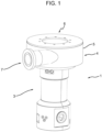
- FIG. 1 we have represented a motor compressor unit compliant with the invention, including a centrifugal motor compressor set 1 illustrated in figure 1 and a liquid / gas separator 2, or purifier, visible in figures 2 and 3 .
- the motor compressor unit is here meant to be mounted on an ocean platform or on a FPSO platform.
- the motor compressor is integrated to the separator. More particularly, the compression stage of the motor compressor is integrated to the separator.
- the motor compressor 1 mainly includes a motor 3 constituted by a high speed electric engine, that is, the frequency of rotation higher than the frequency of the electric supply, leading to rotation of a tree line on which are rigidly mounted one or more wheels with blades, for example, by means of a Hirth joint.
- a motor 3 constituted by a high speed electric engine, that is, the frequency of rotation higher than the frequency of the electric supply, leading to rotation of a tree line on which are rigidly mounted one or more wheels with blades, for example, by means of a Hirth joint.
- the motor compressor 1 includes a single stage of compression 4 including a single wheel with blades mounted on the tree line.
- the stage of compression 4 notably includes a sump 5 in which is placed the compression wheel with blades and which includes an axial or radial entry 6 for admission of gas in the motor compressor and an exit 7 by which the compressed gas is delivered in output by the motor compressor.
- entry 6 is axial.
- the output of the motor compressor is radial, even though in the execution mode of figure 3 , the output is axial, that is, parallel to the general axis of the motor compressor.
- the gas admitted into the motor compressor unit is a humid gas, that is, a gas including a liquid phase constituted of liquid particles in suspension in the gas.
- the gas is first separated by the separator 2 before being delivered to the axial entry 6 of the compressor stage 4.
- the liquid / gas separator 2 thus includes a sump 8, here in an overall cylindrical form, including an entry 9 by which the humid gas travels across the separation stages till sucked in by the motor compressor.
- the liquid / gas separator includes, according to the invention, a first separator stage 10 in which the liquid particles are separated by differentiation from the quantity of the movement then by gravity, then, for example, a second separator stage 11 including a set of obstacles distributed on the journey of the gaseous flow, provided in downstream of the first stage.
- the second stage 11 can be cyclonic.
- the second stage 11 can include several separation stages.
- liquid / gas separator of the first stage can be inertiel.
- a drain D allows evacuating the liquid present in the depth of the separator.
- sump 8 of the separator includes a head 12, overall cylindrical, with enlarged diameter, in which is dispersed the gaseous phase separated by the separator stages 10 and 11 and which internally delimits a case 13 in which is assembled the compressor stage 4.
- This head 12 is located at the opposite end to that of entry 9 of the separator.
- the motor compressor is equipped with a blockage slab 14 which is fixed with the help of screws or pins V (visible in figure 3 ) on the head 12 so that the compressor stage 4 is positioned in the compartment 13 on the journey of the dry gas flow.
- a diffuser 16 for channelling the gaseous flows to the compressor stage, executed, for example, in the form of a truncated cone surface converging towards entry 6 of engine compressor 1, as well as a perforated slab 14' allowing the correction of the flow from the separator to the double bend.
- the motor compressor can be integrated to the separator according to the two geometric configurations, according to the radial or axial direction of the backflow. In the two backflow configurations, all of it constituted by the separator and the motor compressor can be positioned vertically or horizontally.
- the motor compressor preferably adopts a modular configuration and includes a volute 17 which opens in output 7 and which is assembled on a flange E provided internally in the median part of the head 12 and fixed to the latter with the interposition of the airtight seals 15.
- Engine 3 with its tree line 18 on which is fixed a wheel with blades 20, constitutes a set that can be dismantled and which is assembled in a centred manner on the head 12 of the separator and on the volute 17.
- volute 17 is extended according to a substantial part of the height of the head 12 and adopts a much easily executable asymmetrical shape.
- the engine, the tree line and the centrifugal wheel constitute a set that can be dismantled and which is assembled in a centred manner on the head of the separator and on the volute.
- the volute can also be dismantled.
- the head 12 is equipped with bases P allowing the assembling of the motor engine unit on a support platform S.
- the sump of the compressor and the motor are encapsulated in a common sump under pressure and seals the gas handled by the compressor.
- the common sump also includes a blockage slab 14 which is fixed by screwing to the upper part of the separator head. As represented, exit 7 is curved in order to allow the assembling and disassembling of the motor and the compressor.
- the compressor stage 4 is integrated to separator 2 and is placed in a sealed volume, whose pressure is that of the gas handled by the compressor, higher than the atmospheric pressure.
- the compressor and the electric engines are assembled in a common sealed sump.
- the motor is also pressurised between the suction and backflow pressures of the compressor.
- a compact execution including a rotor and a tree line supported by active magnetic bearings.
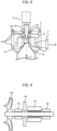
- FIG. 6 On which we have represented the tree line 18 on which is fixed a centrifugal blade 20, we see that the tree of the motor compressor is radially supported by two bearings 22 and 23 positioned on either side of the active part of the motor M. moreover, a single buttress 24 without oil, typically magnetic, maintains the tree line 18 axially.
- This buttress 24 can be positioned between the radial bearings 22 and 23, as illustrated, or be positioned external to these bearings.
- figure 7 diagrammatically illustrates an industrial procedure.
- compressor 1 supplied with dry gas by the separator 2 and from which the output is lopped back in entry, in order to prevent the pumping of the compressor produced by a reversal of the direction of the flow of liquid in the compressor.
- the cooling system is positioned in upstream of the motor compressor unit.
- Figure 7A presents an alternative to the preceding solution, showing the positioning of the cooling system in downstream of the motor compressor unit.
- a cooling unit is provided in upstream or downstream of the separator for cooling the hot gas issued from the motor compressor 1 (in case of pumping), from a motor compressor located in upstream or from another process point.
- the motor compressor unit is configured so as to involve the systems ensuring the implementation of the procedure illustrated in figures 7 and 7A .
- execution which corresponds to a radial backflow configuration, and on which we recognised separator 2 to which is integrated the compressor 4 run by the electric motor 3, we see that the motor compressor unit also is involved in a cooling 25 meant to cool the recirculated gases from compressor 4, a compressor located in upstream or from another process point.
- An anti-pumping valve can also be used on the same frame as the motor compressor unit.
- the cooler 25 can also be interlocked in a double casing around separator 2.
- the source of supply of low voltage of the electric motor and the magnetic bearings can also be subject to integration on the same frame, by considering the local security directives and applicable to the gas handled.
- the invention in which the compressor stage of the motor compressor is integrated in the separator, allows a notable reduction of the control on the ground of all that is constituted by the separator, motor compressor and its auxiliary devices.
- the invention also allows a mass reduction of the motor compressor due to the immersion under pressure of the compressor in the separator.
- the maintenance is also simplified due to the assembling and disassembling facilities by the modular aspect of the assembling.
Landscapes
- Engineering & Computer Science (AREA)
- Mechanical Engineering (AREA)
- General Engineering & Computer Science (AREA)
- Chemical & Material Sciences (AREA)
- Chemical Kinetics & Catalysis (AREA)
- Structures Of Non-Positive Displacement Pumps (AREA)
- Separating Particles In Gases By Inertia (AREA)
- Centrifugal Separators (AREA)
Claims (12)
- Radialmotorverdichtereinheit, einschließlich eines Motorverdichters (1), einschließlich eines Motormittels (3), das eine Kompressorstufe (4) in Rotation versetzt, einschließlich eines Flüssigkeits-/Gasabscheiders (2), wobei der Verdichter in den Abscheider (2) integriert ist, wobei der Flüssigkeits-/Gasabscheider (2) einen Sumpf (8) einschließt, der eine allgemein zylindrische Form aufweist, der mit mindestens einer Gasabscheiderstufe (10, 11) ausgestattet ist, die zum Abscheiden eines feuchten Gases, dem ein Eintritt in den Sumpf gewährt wird, in eine Gasphase und eine Flüssigkeitsphase geeignet ist,wobei der Abscheider (2) eine erste Abscheiderstufe (10) umfasst, in der das feuchte Gas durch mindestens eines von einer Differenzierung von der Menge der Bewegung und dann durch Schwerkraft und Trägheit abgeschieden wird, die jeweils auf die Gasphase und die Flüssigkeitsphase angewendet werden, um ein Trockengas auszugeben; undwobei der Sumpf (8) intern ein Abteil (13) einschließt, einschließlich eines Durchmessers, der höher als der des Rests des Sumpfes (8) ist, in dem die trockene Gasphase strömt, die durch die mindestens eine Abscheiderstufe (10, 11) abgeschieden ist, und in dem die Verdichterstufe (4) des Motorverdichters (1) angeordnet ist, die konfiguriert ist, um mindestens einen Teil der abgeschiedenen Gasphase aufzunehmen, wobei der Motorverdichter (1) in den Abscheider (2) durch den Sumpf (8) des Abscheiders integriert ist, einschließlich eines Kopfes (12), allgemein zylindrisch, mit vergrößertem Durchmesser, in dem in einem Betrieb die durch die mindestens eine Gasabscheiderstufe (10, 11) abgeschiedene Gasphase verteilt ist und der das Abteil (13), in dem die Verdichterstufe (4) angeordnet ist, intern begrenzt, wobei sich der Kopf (12) an dem gegenüberliegenden Ende zu dem eines Eingangs (9) des Abscheiders (2) befindet.
- Radialmotorverdichtereinheit nach Anspruch 1, in der das Abteil (13) durch eine mit dem Motorkompressor (1) verbundene und an dem Sumpf (8) befestigte Sperrplatte (14) versperrt ist.
- Radialmotorverdichtereinheit nach Anspruch 2, in der das Abteil (13) ein luftdichtes Abteil entgegengesetzt der Außenseite des Sumpfes ist, wobei eine luftdichte Dichtung (15) zwischen der Sperrplatte (14) und dem Sumpf (8) platziert ist.
- Radialmotorverdichtereinheit nach einem der Ansprüche 1 bis 3, in der der Sumpf (8) intern ein Führungsmittel (16) der Gasphase in dem Abteil an der Stelle aufweist, an der ein Eingang der Verdichterstufe angeordnet wurde.
- Radialmotorverdichtereinheit nach einem der Ansprüche 1 bis 4, einschließlich eines Kühlmittels (17) eines rezirkulierten Gases und/oder eines stromaufwärts zurückströmenden Gases durch einen Motorverdichter, der sich von dem Motorverdichter (1) unterscheidet, der in den Abscheider (2) integriert ist und der sich stromaufwärts des Abscheiders befindet, wobei das Kühlmittel um den Sumpf (8) herum bereitgestellt ist.
- Radialmotorverdichtereinheit nach einem der Ansprüche 1 bis 5, in der der Abscheider vertikal positioniert ist.
- Radialmotorverdichtereinheit nach einem der Ansprüche 1 bis 6, einschließlich einer einzigen Verdichterstufe.
- Radialmotorverdichtereinheit nach einem der Ansprüche 1 bis 7, einschließlich einer zweiten Abscheiderstufe (11), die aus einem zyklonischen oder einem Doppelkrümmerabscheider ausgewählt ist.
- Radialmotorverdichtereinheit nach einem der Ansprüche 1 bis 8, einschließlich eines Satzes aktiver Magnetlager (22, 23), die die Baumgrenze des Motorverdichters axial und radial unterstützen.
- Radialmotorverdichtereinheit nach einem der Ansprüche 1 bis 9, in der der Verdichter ein axialer Rückstromverdichter ist und einen gekrümmten Ausgang einschließt, der geeignet ist, um die Extraktion des Verdichters zu ermöglichen
- Radialmotorverdichtereinheit nach Anspruch 10, in der das Motormittel (3) und der Verdichter (1) in einem gemeinsamen Sumpf luftdicht gegen das durch den Motorverdichter geförderte Gas angeordnet sind, der in einer luftdichten Weise in dem Sumpf (8) des Abscheiders befestigt ist.
- Radialmotorverdichtereinheit nach einem der Ansprüche 1 bis 9, in der der Verdichter ein radialer Rückstromverdichter ist und einen radialen Ausgang aufweist, wobei das Ganze das Motormittel (3) und ein Rad mit Verdichterschaufeln des Verdichters einschließt, die einen Satz ausmachen, der zerlegt werden kann.
Applications Claiming Priority (2)
| Application Number | Priority Date | Filing Date | Title |
|---|---|---|---|
| FR1551908A FR3033371B1 (fr) | 2015-03-06 | 2015-03-06 | Separateur liquide/gaz et groupe motocompresseur centrifuge dote d'un tel separateur |
| PCT/EP2016/054699 WO2016142306A1 (en) | 2015-03-06 | 2016-03-04 | Liquid / gas separator and centrifugal motor compressor unit equipped with such a separator |
Publications (2)
| Publication Number | Publication Date |
|---|---|
| EP3265682A1 EP3265682A1 (de) | 2018-01-10 |
| EP3265682B1 true EP3265682B1 (de) | 2024-09-25 |
Family
ID=54065946
Family Applications (1)
| Application Number | Title | Priority Date | Filing Date |
|---|---|---|---|
| EP16709317.8A Active EP3265682B1 (de) | 2015-03-06 | 2016-03-04 | Radialmotorverdichteranlage mit einem gas-flüssigkeits-separator |
Country Status (6)
| Country | Link |
|---|---|
| US (1) | US11248630B2 (de) |
| EP (1) | EP3265682B1 (de) |
| JP (1) | JP6878286B2 (de) |
| FR (1) | FR3033371B1 (de) |
| RU (1) | RU2720087C2 (de) |
| WO (1) | WO2016142306A1 (de) |
Families Citing this family (4)
| Publication number | Priority date | Publication date | Assignee | Title |
|---|---|---|---|---|
| DE102016116989A1 (de) * | 2016-09-09 | 2018-03-15 | Endress+Hauser Flowtec Ag | Gasabscheider und Vorrichtung zur Ermittlung eines Durchflusses einer oder mehrerer Komponenten eines mehrphasigen Mediums, insbesondere eines Erdgas-Wasser Gemisches. |
| CN109630433B (zh) * | 2018-12-12 | 2020-06-30 | 孔祥真 | 一种离心式液体中继增压空压机 |
| CN109668354B (zh) * | 2019-02-12 | 2023-07-25 | 珠海格力电器股份有限公司 | 防压缩机用气体轴承磨损的冷媒循环系统及其控制方法 |
| US12313072B2 (en) | 2022-11-30 | 2025-05-27 | Trane International Inc. | Oil-free phase separating compressor |
Family Cites Families (12)
| Publication number | Priority date | Publication date | Assignee | Title |
|---|---|---|---|---|
| NO172555C (no) * | 1989-01-06 | 1993-08-04 | Kvaerner Subsea Contracting As | Undervannsstasjon for behandling og transport av en broennstroem |
| US6299672B1 (en) * | 1999-10-15 | 2001-10-09 | Camco International, Inc. | Subsurface integrated production systems |
| IL133576A (en) | 1999-12-17 | 2003-09-17 | Ide Technologies Ltd | Method of improving the performance of heat-pump installations for making ice |
| DE10010077A1 (de) * | 2000-03-02 | 2001-09-06 | Duerr Dental Gmbh Co Kg | Saugeinheit |
| RU2184876C1 (ru) | 2001-01-19 | 2002-07-10 | Уфимский государственный авиационный технический университет | Эксгаустерная установка |
| FR2866410B1 (fr) * | 2004-02-17 | 2006-05-19 | Gaz De France | Conditionneur d'ecoulement pour canalisation de transport de fluide |
| RU2289727C2 (ru) | 2004-08-20 | 2006-12-20 | Сергей Константинович Баранов | Способ уплотнения газообразной среды и рабочая камера уплотнителя |
| US7866179B2 (en) | 2005-02-23 | 2011-01-11 | I.D.E. Technologies Ltd. | Compact heat pump using water as refrigerant |
| EP1993692B1 (de) * | 2006-03-03 | 2016-08-24 | Dresser-Rand Company | Vorrichtung zur verarbeitung mehrphasiger flüssigkeiten |
| NO328277B1 (no) * | 2008-04-21 | 2010-01-18 | Statoil Asa | Gasskompresjonssystem |
| US9726196B2 (en) * | 2010-10-27 | 2017-08-08 | Dresser-Rand Company | System and cooling for rapid pressurization of a motor-bearing cooling loop for a hermetically sealed motor/compressor system |
| GB2500873A (en) | 2012-03-22 | 2013-10-09 | Corac Energy Technologies Ltd | Pipeline compression system |
-
2015
- 2015-03-06 FR FR1551908A patent/FR3033371B1/fr active Active
-
2016
- 2016-03-04 US US15/556,042 patent/US11248630B2/en active Active
- 2016-03-04 JP JP2017544776A patent/JP6878286B2/ja active Active
- 2016-03-04 EP EP16709317.8A patent/EP3265682B1/de active Active
- 2016-03-04 WO PCT/EP2016/054699 patent/WO2016142306A1/en not_active Ceased
- 2016-03-04 RU RU2017130697A patent/RU2720087C2/ru active
Also Published As
| Publication number | Publication date |
|---|---|
| US11248630B2 (en) | 2022-02-15 |
| JP2018508697A (ja) | 2018-03-29 |
| WO2016142306A1 (en) | 2016-09-15 |
| FR3033371A1 (fr) | 2016-09-09 |
| RU2720087C2 (ru) | 2020-04-24 |
| US20180045224A1 (en) | 2018-02-15 |
| RU2017130697A (ru) | 2019-04-08 |
| FR3033371B1 (fr) | 2018-09-21 |
| RU2017130697A3 (de) | 2019-05-07 |
| EP3265682A1 (de) | 2018-01-10 |
| JP6878286B2 (ja) | 2021-05-26 |
Similar Documents
| Publication | Publication Date | Title |
|---|---|---|
| JP5937268B2 (ja) | 圧縮機段におけるガス除去手段を備えた多段ラジアル圧縮機ユニット | |
| EP3149287B1 (de) | Dichtungsvorrichtung für turbomaschinen | |
| CN107850080B (zh) | 具有级间密封安排的离心式压缩机 | |
| EP2859209B1 (de) | Verdichter mit hohem druckverhältnis und mehrfacher zwischenkühlung sowie zugehörige verfahren | |
| US11248630B2 (en) | Liquid/gas separator and centrifugal motor compressor unit equipped with such a separator | |
| US20180030855A1 (en) | Integrated turboexpander-generator with gas-lubricated bearings | |
| EP3358146B1 (de) | Turbomaschine und verfahren zum betrieb einer turbomaschine | |
| EP3322900B1 (de) | Motorverdichter mit einer dränungsanordnung | |
| US20190085862A1 (en) | Compressor | |
| CN103975164A (zh) | 具有可移除套筒的电动压缩机单元 | |
| US12006941B2 (en) | Compressor with a system for removing liquid from the compressor | |
| JP7163202B2 (ja) | ボルテックスポンプ | |
| CA3160034C (en) | Compressor with a system for removing liquid from the compressor | |
| EP3298283B1 (de) | Untersee-verdichter mit vorrichtung zur reinigung des motorkühlung-lüfters und/oder von hilfslagern |
Legal Events
| Date | Code | Title | Description |
|---|---|---|---|
| STAA | Information on the status of an ep patent application or granted ep patent |
Free format text: STATUS: THE INTERNATIONAL PUBLICATION HAS BEEN MADE |
|
| PUAI | Public reference made under article 153(3) epc to a published international application that has entered the european phase |
Free format text: ORIGINAL CODE: 0009012 |
|
| STAA | Information on the status of an ep patent application or granted ep patent |
Free format text: STATUS: REQUEST FOR EXAMINATION WAS MADE |
|
| 17P | Request for examination filed |
Effective date: 20171006 |
|
| AK | Designated contracting states |
Kind code of ref document: A1 Designated state(s): AL AT BE BG CH CY CZ DE DK EE ES FI FR GB GR HR HU IE IS IT LI LT LU LV MC MK MT NL NO PL PT RO RS SE SI SK SM TR |
|
| AX | Request for extension of the european patent |
Extension state: BA ME |
|
| DAV | Request for validation of the european patent (deleted) | ||
| DAX | Request for extension of the european patent (deleted) | ||
| STAA | Information on the status of an ep patent application or granted ep patent |
Free format text: STATUS: EXAMINATION IS IN PROGRESS |
|
| 17Q | First examination report despatched |
Effective date: 20210503 |
|
| P01 | Opt-out of the competence of the unified patent court (upc) registered |
Effective date: 20230526 |
|
| GRAP | Despatch of communication of intention to grant a patent |
Free format text: ORIGINAL CODE: EPIDOSNIGR1 |
|
| STAA | Information on the status of an ep patent application or granted ep patent |
Free format text: STATUS: GRANT OF PATENT IS INTENDED |
|
| GRAS | Grant fee paid |
Free format text: ORIGINAL CODE: EPIDOSNIGR3 |
|
| INTG | Intention to grant announced |
Effective date: 20240322 |
|
| GRAA | (expected) grant |
Free format text: ORIGINAL CODE: 0009210 |
|
| STAA | Information on the status of an ep patent application or granted ep patent |
Free format text: STATUS: THE PATENT HAS BEEN GRANTED |
|
| AK | Designated contracting states |
Kind code of ref document: B1 Designated state(s): AL AT BE BG CH CY CZ DE DK EE ES FI FR GB GR HR HU IE IS IT LI LT LU LV MC MK MT NL NO PL PT RO RS SE SI SK SM TR |
|
| REG | Reference to a national code |
Ref country code: GB Ref legal event code: FG4D |
|
| REG | Reference to a national code |
Ref country code: CH Ref legal event code: EP |
|
| REG | Reference to a national code |
Ref country code: DE Ref legal event code: R096 Ref document number: 602016089526 Country of ref document: DE |
|
| REG | Reference to a national code |
Ref country code: IE Ref legal event code: FG4D |
|
| REG | Reference to a national code |
Ref country code: LT Ref legal event code: MG9D |
|
| PG25 | Lapsed in a contracting state [announced via postgrant information from national office to epo] |
Ref country code: GR Free format text: LAPSE BECAUSE OF FAILURE TO SUBMIT A TRANSLATION OF THE DESCRIPTION OR TO PAY THE FEE WITHIN THE PRESCRIBED TIME-LIMIT Effective date: 20241226 Ref country code: FI Free format text: LAPSE BECAUSE OF FAILURE TO SUBMIT A TRANSLATION OF THE DESCRIPTION OR TO PAY THE FEE WITHIN THE PRESCRIBED TIME-LIMIT Effective date: 20240925 |
|
| PG25 | Lapsed in a contracting state [announced via postgrant information from national office to epo] |
Ref country code: BG Free format text: LAPSE BECAUSE OF FAILURE TO SUBMIT A TRANSLATION OF THE DESCRIPTION OR TO PAY THE FEE WITHIN THE PRESCRIBED TIME-LIMIT Effective date: 20240925 |
|
| PG25 | Lapsed in a contracting state [announced via postgrant information from national office to epo] |
Ref country code: LV Free format text: LAPSE BECAUSE OF FAILURE TO SUBMIT A TRANSLATION OF THE DESCRIPTION OR TO PAY THE FEE WITHIN THE PRESCRIBED TIME-LIMIT Effective date: 20240925 |
|
| PG25 | Lapsed in a contracting state [announced via postgrant information from national office to epo] |
Ref country code: RS Free format text: LAPSE BECAUSE OF FAILURE TO SUBMIT A TRANSLATION OF THE DESCRIPTION OR TO PAY THE FEE WITHIN THE PRESCRIBED TIME-LIMIT Effective date: 20241225 |
|
| REG | Reference to a national code |
Ref country code: NL Ref legal event code: MP Effective date: 20240925 |
|
| PG25 | Lapsed in a contracting state [announced via postgrant information from national office to epo] |
Ref country code: RS Free format text: LAPSE BECAUSE OF FAILURE TO SUBMIT A TRANSLATION OF THE DESCRIPTION OR TO PAY THE FEE WITHIN THE PRESCRIBED TIME-LIMIT Effective date: 20241225 Ref country code: LV Free format text: LAPSE BECAUSE OF FAILURE TO SUBMIT A TRANSLATION OF THE DESCRIPTION OR TO PAY THE FEE WITHIN THE PRESCRIBED TIME-LIMIT Effective date: 20240925 Ref country code: GR Free format text: LAPSE BECAUSE OF FAILURE TO SUBMIT A TRANSLATION OF THE DESCRIPTION OR TO PAY THE FEE WITHIN THE PRESCRIBED TIME-LIMIT Effective date: 20241226 Ref country code: FI Free format text: LAPSE BECAUSE OF FAILURE TO SUBMIT A TRANSLATION OF THE DESCRIPTION OR TO PAY THE FEE WITHIN THE PRESCRIBED TIME-LIMIT Effective date: 20240925 Ref country code: BG Free format text: LAPSE BECAUSE OF FAILURE TO SUBMIT A TRANSLATION OF THE DESCRIPTION OR TO PAY THE FEE WITHIN THE PRESCRIBED TIME-LIMIT Effective date: 20240925 |
|
| REG | Reference to a national code |
Ref country code: AT Ref legal event code: MK05 Ref document number: 1726838 Country of ref document: AT Kind code of ref document: T Effective date: 20240925 |
|
| PG25 | Lapsed in a contracting state [announced via postgrant information from national office to epo] |
Ref country code: NL Free format text: LAPSE BECAUSE OF FAILURE TO SUBMIT A TRANSLATION OF THE DESCRIPTION OR TO PAY THE FEE WITHIN THE PRESCRIBED TIME-LIMIT Effective date: 20240925 |
|
| PG25 | Lapsed in a contracting state [announced via postgrant information from national office to epo] |
Ref country code: IS Free format text: LAPSE BECAUSE OF FAILURE TO SUBMIT A TRANSLATION OF THE DESCRIPTION OR TO PAY THE FEE WITHIN THE PRESCRIBED TIME-LIMIT Effective date: 20250125 Ref country code: PT Free format text: LAPSE BECAUSE OF FAILURE TO SUBMIT A TRANSLATION OF THE DESCRIPTION OR TO PAY THE FEE WITHIN THE PRESCRIBED TIME-LIMIT Effective date: 20250127 |
|
| PG25 | Lapsed in a contracting state [announced via postgrant information from national office to epo] |
Ref country code: RO Free format text: LAPSE BECAUSE OF FAILURE TO SUBMIT A TRANSLATION OF THE DESCRIPTION OR TO PAY THE FEE WITHIN THE PRESCRIBED TIME-LIMIT Effective date: 20240925 Ref country code: SM Free format text: LAPSE BECAUSE OF FAILURE TO SUBMIT A TRANSLATION OF THE DESCRIPTION OR TO PAY THE FEE WITHIN THE PRESCRIBED TIME-LIMIT Effective date: 20240925 |
|
| PG25 | Lapsed in a contracting state [announced via postgrant information from national office to epo] |
Ref country code: ES Free format text: LAPSE BECAUSE OF FAILURE TO SUBMIT A TRANSLATION OF THE DESCRIPTION OR TO PAY THE FEE WITHIN THE PRESCRIBED TIME-LIMIT Effective date: 20240925 |
|
| PG25 | Lapsed in a contracting state [announced via postgrant information from national office to epo] |
Ref country code: EE Free format text: LAPSE BECAUSE OF FAILURE TO SUBMIT A TRANSLATION OF THE DESCRIPTION OR TO PAY THE FEE WITHIN THE PRESCRIBED TIME-LIMIT Effective date: 20240925 Ref country code: AT Free format text: LAPSE BECAUSE OF FAILURE TO SUBMIT A TRANSLATION OF THE DESCRIPTION OR TO PAY THE FEE WITHIN THE PRESCRIBED TIME-LIMIT Effective date: 20240925 |
|
| PG25 | Lapsed in a contracting state [announced via postgrant information from national office to epo] |
Ref country code: PL Free format text: LAPSE BECAUSE OF FAILURE TO SUBMIT A TRANSLATION OF THE DESCRIPTION OR TO PAY THE FEE WITHIN THE PRESCRIBED TIME-LIMIT Effective date: 20240925 Ref country code: CZ Free format text: LAPSE BECAUSE OF FAILURE TO SUBMIT A TRANSLATION OF THE DESCRIPTION OR TO PAY THE FEE WITHIN THE PRESCRIBED TIME-LIMIT Effective date: 20240925 |
|
| PG25 | Lapsed in a contracting state [announced via postgrant information from national office to epo] |
Ref country code: SK Free format text: LAPSE BECAUSE OF FAILURE TO SUBMIT A TRANSLATION OF THE DESCRIPTION OR TO PAY THE FEE WITHIN THE PRESCRIBED TIME-LIMIT Effective date: 20240925 |
|
| REG | Reference to a national code |
Ref country code: DE Ref legal event code: R097 Ref document number: 602016089526 Country of ref document: DE |
|
| PG25 | Lapsed in a contracting state [announced via postgrant information from national office to epo] |
Ref country code: DK Free format text: LAPSE BECAUSE OF FAILURE TO SUBMIT A TRANSLATION OF THE DESCRIPTION OR TO PAY THE FEE WITHIN THE PRESCRIBED TIME-LIMIT Effective date: 20240925 |
|
| PGFP | Annual fee paid to national office [announced via postgrant information from national office to epo] |
Ref country code: CH Payment date: 20250401 Year of fee payment: 10 |
|
| PLBE | No opposition filed within time limit |
Free format text: ORIGINAL CODE: 0009261 |
|
| STAA | Information on the status of an ep patent application or granted ep patent |
Free format text: STATUS: NO OPPOSITION FILED WITHIN TIME LIMIT |
|
| 26N | No opposition filed |
Effective date: 20250626 |
|
| PG25 | Lapsed in a contracting state [announced via postgrant information from national office to epo] |
Ref country code: SE Free format text: LAPSE BECAUSE OF FAILURE TO SUBMIT A TRANSLATION OF THE DESCRIPTION OR TO PAY THE FEE WITHIN THE PRESCRIBED TIME-LIMIT Effective date: 20240925 |
|
| PG25 | Lapsed in a contracting state [announced via postgrant information from national office to epo] |
Ref country code: MC Free format text: LAPSE BECAUSE OF FAILURE TO SUBMIT A TRANSLATION OF THE DESCRIPTION OR TO PAY THE FEE WITHIN THE PRESCRIBED TIME-LIMIT Effective date: 20240925 |
|
| PG25 | Lapsed in a contracting state [announced via postgrant information from national office to epo] |
Ref country code: LU Free format text: LAPSE BECAUSE OF NON-PAYMENT OF DUE FEES Effective date: 20250304 |
|
| REG | Reference to a national code |
Ref country code: BE Ref legal event code: MM Effective date: 20250331 |
|
| PG25 | Lapsed in a contracting state [announced via postgrant information from national office to epo] |
Ref country code: HR Free format text: LAPSE BECAUSE OF FAILURE TO SUBMIT A TRANSLATION OF THE DESCRIPTION OR TO PAY THE FEE WITHIN THE PRESCRIBED TIME-LIMIT Effective date: 20240925 Ref country code: FR Free format text: LAPSE BECAUSE OF NON-PAYMENT OF DUE FEES Effective date: 20250331 |
|
| PG25 | Lapsed in a contracting state [announced via postgrant information from national office to epo] |
Ref country code: BE Free format text: LAPSE BECAUSE OF NON-PAYMENT OF DUE FEES Effective date: 20250331 |
|
| PG25 | Lapsed in a contracting state [announced via postgrant information from national office to epo] |
Ref country code: IE Free format text: LAPSE BECAUSE OF NON-PAYMENT OF DUE FEES Effective date: 20250304 |
|
| REG | Reference to a national code |
Ref country code: CH Ref legal event code: U11 Free format text: ST27 STATUS EVENT CODE: U-0-0-U10-U11 (AS PROVIDED BY THE NATIONAL OFFICE) Effective date: 20260401 |
|
| PGFP | Annual fee paid to national office [announced via postgrant information from national office to epo] |
Ref country code: GB Payment date: 20260220 Year of fee payment: 11 |
|
| PGFP | Annual fee paid to national office [announced via postgrant information from national office to epo] |
Ref country code: DE Payment date: 20260219 Year of fee payment: 11 Ref country code: NO Payment date: 20260223 Year of fee payment: 11 |
|
| PGFP | Annual fee paid to national office [announced via postgrant information from national office to epo] |
Ref country code: IT Payment date: 20260219 Year of fee payment: 11 |